TM 5-6115-586-34
DEPARTMENT OF THE ARMY TECHNICAL MANUAL
TECHNICAL MANUAL
DIRECT SUPPORT AND GENERAL SUPPORT
MAINTENANCE MANUAL
POWER PLANT, UTILITY, GAS
TURBINE ENGINE DRIVEN
(LIBBY WELDING CO. MODEL LPU-71)
FSN 6115-165-3842
This copy is a reprint which includes current pages from Changes 1
HEADQUARTERS, DEPARTMENT OF THE ARMY
JUNE 1972
WARNINGTake particular heed to specific warnings and cautions throughout this manual.
HIGH VOLTAGEis used in the operation of this equipment.
DEATHor severe burns may result if personnel fail to observe safety precautions. Do not operate thisequipment until the ground terminal has been connected to a suitable ground. Disconnectthe battery negative cable before removing or installing components in any electrical pane orsystem.
Before servicing or repairing any part of the power plant, be sure that it is not connected toanother power plant that is operating. Do not service the power plant while it is connected forstandby operation Ground the ignition plug or ignition unit before removal by grounding thehigh tension lead contact spring to the ignition immediately upon removal of the lead.
HIGH SPEED ROTATION AND HIGH FREQUENCY NOISEare present during operation of this equipment.
DEATHor severe injury or loss of hearing may result if personnel fail to observe safety precautions.During unit starting, operation, or testing stand clear of the sides of the engine. Extreme caremust be exercised to prevent debris or other foreign material from entering the air inlet.Turbine or compressor failure induced by foreign material entering the unit may besufficiently violent to cause severe damage to internal components with possible danger topersonnel in the immediate area. Operators working ii the area of equipment generating highfrequency noises will be required to wear ear plugs to prevent permanent damage to hearing.Safety or medical officer will provide examination requirements an, federal stock number forear plugs and ear protectors.
DANGEROUS GASES AND EXTREME HEATare generated as a result of operating this equipment.
DEATHor severe injury may occur if personnel fail to observe safety precautions. Stay clear ofexhaust opening during operation of the power plant. Allow exhaust and heat exchangercomponents to cool before al tempting maintenance on or near them. Extreme exhaust heatis generated by the gas turbine engine Do not operate power plant in enclosed area unlessadequate ventilation of exhaust gases is provided Exhaust discharge contains noxious anddeadly fumes. Do not smoke or use open flame in vicinity when servicing batteries. Batteriesgenerate explosive gas during charging. Some solvents used for cleaning of componentsduring repair are toxic and shall be used only in well ventilated areas. Observe specificwarnings in this manual
LIQUIDS AND GASES UNDER PRESSUREare generated as a result of operation of this equipment.
INJURYmay result if personnel fail to observe safety precautions. Keep hands and other exposedareas of the body away from any malfunction of plumbing in refrigeration system, hot watersystem, bleed air system, and lubrication system. Wear protective gloves and other clothingwhen handling heater components or servicing refrigeration as directed by specific warningsin this manual.
TM 5-6115-586-34C 1
CHANGE HEADQUARTERSDEPARTMENT OF THE ARMY
No. 1 WASHINGTON, DC 2 August 1974
Direct Support and General Support Maintenance Manual
POWER PLANT, UTILITY; GAS TURBINE ENGINEDRIVEN (LIBBY WELDING CO. MODEL LPU-71)
FSN 6115-937-0929 (NON-WINTERIZED)FSN 6115-134-0825 (WINTERIZED)
TM 5-6115-586-34, 15 June 1972, is changed as follows:
The title is changed as shown above.Page 2 of cover: Add to Warnings:
Cleaning solvent, PD-680, used for cleaning, is POTENTIALLY DANGEROUS CHEMICAL. Do notuse near open flame. Flash point of solvent is 100° - 138°F. (38° - 59°C.).
Page 1-1, paragraph 1-3, lines 5 through 8 are changed to: Commander, US Army Troop Support Command,ATTN: AMSTS-MPP, 4300 Goodfellow Boulevard, St. Louis, MO 63120.
By Order of the Secretary of the Army:CREIGHTON W. ABRAMSGeneral, United States Army
Official: Chief of StaffVERNE L. BOWERSMajor General, United States ArmyThe Adjutant General
Distribution:To be distributed in accordance with DA Form 12-25A (qty rqr block No. 639) Direct and General Support
Maintenance requirements for MUST System.
TM 5-6115-586-34
TECHNICAL MANUAL HEADQUARTERSDEPARTMENT OF THE ARMY
No. 5-6115-586-34 WASHINGTON, D.C., 15 June 1972.
DIRECT SUPPORT AND GENERAL SUPPORT MAINTENANCE MANUAL
POWER PLANT, UTILITY: GAS TURBINE ENGINE DRIVEN
LIBBY WELDING CO. MODEL LPU-71
FSN 6115-165-3842
Paragraph PageCHAPTER 1 INTRODUCTION
Section I. General .................................................................................. 1-1 1-1II. Description and data .............................................................. 1-4 1-4
CHAPTER 2. DIRECT SUPPORT AND GENERAL SUPPORTMAINTENANCE INSTRUCTIONS
Section I. Repair parts, Special Tools, and equipment............................ 2-1 2-1II. Troubleshooting ..................................................................... 2-3 2-3
III. General Maintenance ............................................................ 2-5 2-11IV. Removal and Installation of Major Components and Auxiliaries 2-10 2-21
CHAPTER 3. REPAIR OF ENGINESection I. Engine Electrical and Plumbing Installation ........................... 3-1 3-1
II. Engine Accessories ................................................................ 3-4 3-15III. Dual Pad Accessory Drive Assembly ..................................... 3-9 3-24IV. Accessory Gearcase Assembly............................................... 3-15 3-30V. Compressor and Turbine Assembly ....................................... 3-21 3-34
CHAPTEI 4. REPAIR OF SKID ASSEMBLY .............................................. 4-1 4-1
CHAPTER 5. REPAIR OF ELECTRICAL COMPONENTSSection I. Power Plant Electrical Installation........................................... 5-1 5-1
II. Engine and Skid Electrical Installation ................................... 5-32 5-60
CHAPTER 6. REPAIR OF CONDITIONED AIR COOLING SYSTEMSection I. Tube Assemblies and Plumbing Fittings ................................ 6-1 6-1
II. Compressors, Condensers and Evaporators .......................... 6-3 6-13III. Receivers ............................................................................... 6-7 6-16IV. Motor Driven Tube Axial Fan (Recirculating) ......................... 6-8 6-19V. Motor Driven Tube Axial Fan (Condenser).............................. 6-9 6-25
CHAPTER 7. REPAIR OF BLEED AIR AND EXHAUSTHEATING INSTALLATION ............................................ 7-1 7-1
CHAPTER 8. REPAIR OF WATER SYSTEM PLUMBING INSTALLATIONSection I. Tube Assemblies, Fittings, and Manual Valves....................... 8-1 8-1
II. Surge Tank and Pressure Switch............................................ 8-5 8-1III. Hot Water Tank, Thermostatic Switch, and Relief Valves ...... 8-9 8-2
CHAPTER 9. REPAIR OF ENCLOSURE ASSEMBLY ................................ 9-1 9-1
CHAPTER 10. REPAIR OF ACCESSORY COMPONENTSSection I. General Information................................................................ 10-1 10-1
II. Compressed Air and Vacuum System Accessory Components 10-2 10-1III. Water System Accessory Components................................... 10-5 10-5IV. External Fuel Filter Assembly: ............................................... 10-7 10-7V. Electrical Cable Accessory Components................................. 10-12 10-9
VI. Conditioned Air System Accessory Components ................... 10-19 10-9
APPENDIX A. REFERENCES....................................................................... A-1INDEX .................................................................................. I-1
i
TM 5-6115-586-34LIST OF ILLUSTRATIONS
Figure Title Page2-1. Refrigeration service unit ........................................................................................................... 2-62-2. Refrigeration service unit panel details ....................................................................................... 2-72-3. Service unit connected to power plant ........................................................................................ 2-92-4. Refrigeration service unit internal details..................................................................................... 2-102-5. Removal of engine and skid assembly (sheet 1 of 3) .................................................................. 2-222-5. Removal of engine and skid assembly (sheet 2 of 3) .................................................................. 2-232-5. Removal of engine and skid assembly (sheet 3 of 3) .................................................................. 2-242-6. Removal of gas turbine engine.................................................................................................... 2-263-1. Gas turbine engine wire harness installation................................................................................ 3-23-2. Gas turbine engine wire harness assembly.................................................................................. 3-33-3. Gas turbine engine wire harness diagram and wire identification chart ....................................... 3-43-4. Engine and skid plumbing installation (sheet 1 of 5) ................................................................... 3-63-4. Engine and skid plumbing installation (sheet 2 of 5) ................................................................... 3-83-4. Engine and skid plumbing installation (sheet 3 of 5) ................................................................... 3-103-4. Engine and skid plumbing installation (sheet 4 of 5) .................................................................... 3-123-4. Engine and skid plumbing installation (sheet 5 of 5) .................................................................... 3-143-5. Starter clutch assembly............................................................................................................... 3-163-6. Pawls installed in spider ............................................................................................................. 3-183-7. Using clutch torquing holder and torque wrench adapter to check clutch slip torque .................... 3-193-8. Fuel control assembly ................................................................................................................. 3-203-9. Fuel atomizer assembly ............................................................................................................. 3-223-10. Oil temperature regulator valve................................................................................................... 3-233-11. Test set-up for oil temperature regulator ..................................................................................... 3-243-12. Gas turbine engine assembly (sheet 1 of 2) ................................................................................ 3-253-12. Gas turbine engine assembly (sheet 2 of 2)................................................................................. 3-263-13. Dual pad accessory drive assembly ............................................................................................ 3-273-14. Inspection of retainer................................................................................................................... 3-283-15. Inspection of seal ........................................................................................................................ 3-293-16. Determining shim requirements for input seal assembly ............................................................. 3-303-17. Accessory gearcase assembly .................................................................................................... 3-313-18. Installation of seal ....................................................................................................................... 3-323-19. Installation of seal ...................................................................................................................... 3-333-20. Inspection of torus ...................................................................................................................... 3-353-21. Inspection of torus ...................................................................................................................... 3-363-22. Inspection of liner ....................................................................................................................... 3-373-23. Inspection of nozzle .................................................................................................................... 3-383-24. Repair of turbine plenum ............................................................................................................ 3-403-25. Repair of torus ........................................................................................................................... 3-414-1. Fuel boost pump, exploded view................................................................................................. 4-24-2. Air inlet duct assembly, exploded view........................................................................................ 4-44-3. Air inlet plenum assembly, upper, exploded view ........................................................................ 4-64-4. Air inlet plenum assembly, lower, exploded view......................................................................... 4-74-5. Heat shield assembly, upper, exploded view ............................................................................... 4-94-6. Heat shield assembly, lower, exploded view................................................................................ 4-104-7. Engine skid assembly, exploded view ........................................................................................ 4-124-8. Engine skid sub-assembly, exploded view .................................................................................. 4-145-1. DC power branched wire harness assembly ................................................................................ 5-25-2. Power plant dc power branched wire harness assembly .............................................................. 5-45-3. DC power branched wire harness assembly ................................................................................ 5-55-4. Water system wire harness assembly.......................................................................................... 5-65-5. Water system branched wire harness assembly .......................................................................... 5-75-6. Water pumps wire harness assembly .......................................................................................... 5-85-7. Air conditioning system branched wire harness assembly ........................................................... 5-93-8. Air conditioning system wire harness assembly .......................................................................... 5-113-9. Recirculating fans wire harness assembly ................................................................................... 5-135-10. Recirculating fans wire harness assembly .................................................................................. 5-143-11. Recirculating fans wire harness assembly .................................................................................. 5-153-12. 400 Hz auxiliary power wire harness assembly............................................................................ 5-165-13. Anti-ice thermostat wire harness assembly ................................................................................. 5-173-14. Condenser fans wire harness assembly ...................................................................................... 5-185-15. Condenser fans wire harness assembly ...................................................................................... 5-205-16. Remote power output wire harness assembly.............................................................................. 5-223-17. Compressor wire harness assembly ............................................................................................ 5-243-18. Compressors wire harness assembly........................................................................................... 5-255-19. Compressors wire harness assembly........................................................................................... 5-25
ii
TM 5-6115-586-34Figure Title Page5-20. Compressor and exhaust fans wire harness assembly ................................................................ 5-275-21. AC power wire harness assembly ............................................................................................... 5-285-22. Temperature sensors wire harness assembly ............................................................................. 5-305-23. Temperature sensors wire harness assembly ............................................................................. 5-325-24. Battery wire harness assembly .................................................................................................... 5-345-25. Heat valves wire harness assembly ............................................................................................ 5-355-26. Air conditioning power wire harness assembly ............................................................................ 5-375-27. DC power wire harness assembly................................................................................................ 5-385-28. Compressors wire harness assembly........................................................................................... 5-395-29. Remote fans wire harness assembly ........................................................................................... 5-405-30. Condenser fans wire harness assembly ...................................................................................... 5-415-31. Recirculating fans wire harness assembly ................................................................................... 5-425-32. Remove power wire harness assembly........................................................................................ 5-435-33. Auxiliary power tray assembly .................................................................................................... 5-455-34. 400 Hz auxiliary power wire harness assembly............................................................................ 5-475-35. 400 Hz auxiliary output 1 wire harness assembly ........................................................................ 5-485-36. 400 Hz auxiliary output 2 wire harness assembly ........................................................................ 5-495-37. Water heater wire harness assembly .......................................................................................... 5-505-38. Receptacle panel wire harness assembly ................................................................................... 5-515-30. 60 Hz output wire harness assembly. .......................................................................................... 5-525-40. 400 Hz output wire harness assembly ........................................................................................ 5-535-41. 400 Hz output wire harness assembly ........................................................................................ 5-545-42. DC Standby wire harness assembly ........................................................................................... 5-555-43. Slave receptacle cable assembly ............................................................................................... 5-555-44. 60 Hz output wire harness assembly .......................................................................................... 5-565-45. Air conditioning and heat control panel wire harness assembly ................................................... 5-585-46. Electrical leads ........................................................................................................................... 5-595-47. Engine skid power plant wire harness assembly ......................................................................... 5-615-48. Power wire harness assembly ..................................................................................................... 5-635-40. Battery wire harness assembly .................................................................................................... 5-646-1. Conditioned air cooling system (sheet 1 of 6) ............................................................................. 6-26-1. Conditioned air cooling system (sheet 2 of 6) ............................................................................. 6-46-1. Conditioned air cooling system (sheet 3 of 6) ............................................................................. 6-66-1. Conditioned air cooling system (sheet 4 of 6) ............................................................................. 6-86-1. Conditioned air cooling system (sheet 5 of 6) ............................................................................. 6-106-1. Conditioned air cooling system (sheet 6 of 6) ............................................................................. 6-126-2. Thermostatic switch assembly inspection requirements .............................................................. 6-146-3. Refrigerant leakage test setup .................................................................................................... 6-146-4. Refrigerant leakage test setup .................................................................................................... 6-166-5,. Liquid refrigerant receiver .......................................................................................................... 6-176-6. Refrigerant leakage test setup .................................................................................................... 6-186-7. Tube axial motor driven fan ....................................................................................................... 6-206-8. Holding fixture torque wrench...................................................................................................... 6-216-9. Schematic wiring diagram .......................................................................................................... 6-226-10. End bell inspection requirements................................................................................................. 6-226-11. Rotor assembly inspection requirements .................................................................................... 6-236-12. Fan housing assembly inspection requirements .......................................................................... 6-236-13 . Bearing installation ..................................................................................................................... 6-246-14. End play measurement ............................................................................................................... 6-256-15. Tube axial motor driven fan ....................................................................................................... 6-266-16. Holding fixture torque wrench ..................................................................................................... 6-276-17 . Schematic wiring diagram .......................................................................................................... 6-286-18. End bell inspection requirements................................................................................................. 6-286-19. Rotor assembly inspection requirements .................................................................................... 6-296-20. Fan housing assembly inspection requirements .......................................................................... 6-296-21. Bearing installation ..................................................................................................................... 6-306-22. End play measurement ............................................................................................................... 6-317-1. Bleed air and exhaust heating installation (sheet 1 of 3) ............................................................. 7-27-1. Bleed air and exhaust heating installation (sheet 2 of 3) ............................................................. 7-47-1. Bleed air and exhaust heating installation (sheet 3 of 3) ............................................................. 7-69-1. Enclosure assembly (sheet 1 of 10) ............................................................................................ 9-29-1. Enclosure assembly (sheet-2 of 10) ............................................................................................ 9-49-1. Enclosure assembly (sheet 3 of 10) ............................................................................................ 9-69-1. Enclosure assembly (sheet 4 of 10) ............................................................................................ 9-89-1. Enclosure assembly (sheet 5 of 10) ............................................................................................ 9-109-1. Enclosure assembly (sheet 6 of 10).: .......................................................................................... 9-129-1. Enclosure assembly (sheet 7 of 10) ............................................................................................ 9-13
iii

TM 5-6115-586-34
Figure Title Page
9-1. Enclosure assembly (sheet 8 or 10) ............................................................................................ 9-149-1. Enclosure assembly (sheet 9 of 10) ............................................................................................ 9-159-1. Enclosure assembly (sheet 10 of 10) .......................................................................................... 9-169-2. Shell assembly (sheet 1 of 9) ..................................................................................................... 9-179-2. Shell assembly (sheet 2 of 9) ..................................................................................................... 9-189-2. Shell assembly (sheet 3 of 9) ..................................................................................................... 9-209-2. Shell assembly (sheet 4 of 9) ..................................................................................................... 9-229-2. Shell assembly (sheet 5 of 9) ..................................................................................................... 9-249-2. Shell assembly (sheet 6 of 9) ..................................................................................................... 9-269-2. Shell assembly (sheet 7 of 9) ..................................................................................................... 9-289-2. Shell assembly (sheet 8 of 9) ..................................................................................................... 9-309-2. Shell assembly (sheet 9 of 9) ..................................................................................................... 9-3210-1. Inflation and deflation ejector assembly ...................................................................................... 10-210-2. Box and valve manifold assembly .............................................................................................. 10-410-3. Compressed air hose assembly and vacuum hose assembly ..................................................... 10-510-4. Water system accessory components ........................................................................................ 10-610-5. External fuel filter assembly ....................................................................................................... 10-810-6. Conditioned air system accessory components .......................................................................... 10-10FO-1 Control panel wire harness assembly ......................................................................................... FO-1FO-2. Engine skid wire harness assembly ............................................................................................ FO-2
iv
TM 5-6115-586-34CHAPTER 1
INTRODUCTIONSection I. GENERAL
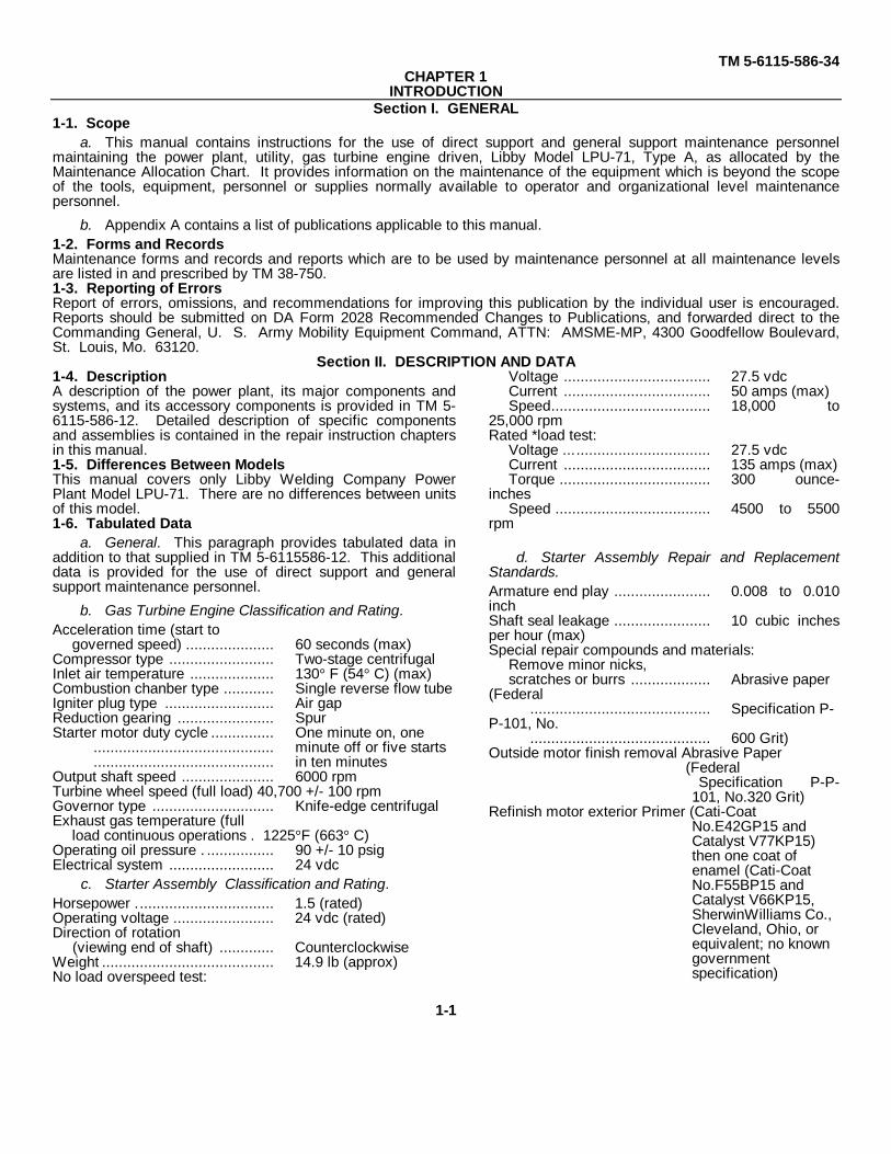
1-1. Scopea. This manual contains instructions for the use of direct support and general support maintenance personnel
maintaining the power plant, utility, gas turbine engine driven, Libby Model LPU-71, Type A, as allocated by theMaintenance Allocation Chart. It provides information on the maintenance of the equipment which is beyond the scopeof the tools, equipment, personnel or supplies normally available to operator and organizational level maintenancepersonnel.
b. Appendix A contains a list of publications applicable to this manual.1-2. Forms and RecordsMaintenance forms and records and reports which are to be used by maintenance personnel at all maintenance levelsare listed in and prescribed by TM 38-750.1-3. Reporting of ErrorsReport of errors, omissions, and recommendations for improving this publication by the individual user is encouraged.Reports should be submitted on DA Form 2028 Recommended Changes to Publications, and forwarded direct to theCommanding General, U. S. Army Mobility Equipment Command, ATTN: AMSME-MP, 4300 Goodfellow Boulevard,St. Louis, Mo. 63120.
Section II. DESCRIPTION AND DATA1-4. DescriptionA description of the power plant, its major components andsystems, and its accessory components is provided in TM 5-6115-586-12. Detailed description of specific componentsand assemblies is contained in the repair instruction chaptersin this manual.1-5. Differences Between ModelsThis manual covers only Libby Welding Company PowerPlant Model LPU-71. There are no differences between unitsof this model.1-6. Tabulated Data
a. General. This paragraph provides tabulated data inaddition to that supplied in TM 5-6115586-12. This additionaldata is provided for the use of direct support and generalsupport maintenance personnel.
b. Gas Turbine Engine Classification and Rating.Acceleration time (start to
governed speed) ..................... 60 seconds (max)Compressor type ......................... Two-stage centrifugalInlet air temperature .................... 130° F (54° C) (max)Combustion chanber type ............ Single reverse flow tubeIgniter plug type .......................... Air gapReduction gearing ....................... SpurStarter motor duty cycle ............... One minute on, one
........................................... minute off or five starts
........................................... in ten minutesOutput shaft speed ...................... 6000 rpmTurbine wheel speed (full load) 40,700 +/- 100 rpmGovernor type ............................. Knife-edge centrifugalExhaust gas temperature (full
load continuous operations . 1225°F (663° C)Operating oil pressure . ................ 90 +/- 10 psigElectrical system ......................... 24 vdc
c. Starter Assembly Classification and Rating.Horsepower ................................. 1.5 (rated)Operating voltage ........................ 24 vdc (rated)Direction of rotation
(viewing end of shaft) ............. CounterclockwiseWeight ......................................... 14.9 lb (approx)No load overspeed test:
Voltage ................................... 27.5 vdcCurrent ................................... 50 amps (max)Speed...................................... 18,000 to
25,000 rpmRated *load test:
Voltage ................................... 27.5 vdcCurrent ................................... 135 amps (max)Torque .................................... 300 ounce-
inchesSpeed ..................................... 4500 to 5500
rpm
d. Starter Assembly Repair and ReplacementStandards.Armature end play ....................... 0.008 to 0.010inchShaft seal leakage ....................... 10 cubic inchesper hour (max)Special repair compounds and materials:
Remove minor nicks,scratches or burrs ................... Abrasive paper
(Federal........................................... Specification P-
P-101, No............................................ 600 Grit)
Outside motor finish removal Abrasive Paper(Federal
Specification P-P-101, No.320 Grit)
Refinish motor exterior Primer (Cati-CoatNo.E42GP15 andCatalyst V77KP15)then one coat ofenamel (Cati-CoatNo.F55BP15 andCatalyst V66KP15,SherwinWilliams Co.,Cleveland, Ohio, orequivalent; no knowngovernmentspecification)
1-1
TM 5-6115-586-34
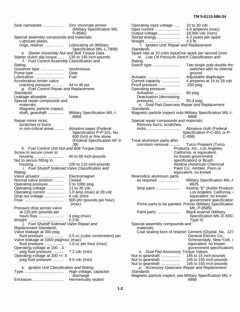
Seal nameplate .................. Zinc chromate primer(Military Specification MILP-8585)
Special assembly compounds and materials:Lubricate plates,rings, retainer ................. Lubricating oil (Military
Specification MIL-L-7808)e. Starter Assembly Nut and Bolt Torque Data.
Starter clutch slip torque ..... 135 to 145 inch-poundsf. Fuel Control Assembly Classification and
Rating.Governor type .................... IsochronousPump type .......................... GearLubrication ......................... FuelAcceleration limiter valve
cracking pressure .......... 44 to 46 psig. Fuel Control Repair and Replacement
Standards.Leakage allowable .............. NoneSpecial repair compounds and
materials:Magnetic particle inspect,shaft, gearshaft .............. Military Specification MIL-I-
6868Repair minor nicks,
scratches or burrsin non-critical areas ........ Abrasive paper (Federal
Specification P-P-101, No.600 Grit) or fine stone(Federal Specification AF-3-JB)
h. Fuel Control Unit Nut and Bolt Torque Data.Screw to secure cover to
housing .......................... 40 to 60 inch-poundsNut to secure fitting to
housing .......................... 100 to 110 inch-poundsi. Fuel Shutoff Solenoid Valve Classification and
Rating.Valve actuator .................... ElectromagnetNormal valve position ......... ClosedOperating pressure ............. 0 to 1000 psigOperating voltage ............... 11 to 30 vdcOperating current ............... 1.0 amp (max) at 28 vdcDrop out voltage ................. 4 vdc (miniFlow .................................. 500 phr (pounds per hour)
(max)Pressure drop across valve
at 120 phr (pounds perhour) flow ...................... 4 psig (max)
Weight ............................... 0.3 lbj. Fuel Shutoff Solenoid Valve Repair and
Replacement Standards.Valve leakage at 300 psig
fluid pressure ................. 0.5 cc (cubic centimeters) perValve leakage at 1000 psighour (max)
fluid pressure ................. 1.0 cc per hour (max)Operating voltage at 100 -.3
psig fluid pressure ......... 7.2 vdc (min)Operating voltage at 300 +/- 3
psig fluid pressure ......... 9.0 vdc (min)
k. Ignition Unit Classification and Rating.Type. .................................. High voltage, capacitor
dischargeEnclosure............................ Hermetically sealed
Operating input voltage ..... 10 to 30 vdcInput current ...................... 4.5 amperes (max)Output voltage ................... 18,000 vdc (nom)Stored energy .................... 4.3 joules per sparkWeight .............................. 3.5 lb
l. Ignition Unit 'Repair and ReplacementStandards.Spark rate at 10 volts inputOne spark per second (mini
m. Low Oil Pressure Switch Classification andRating.Switch type ........................ Two single pole double throw
switches with no internalground
Actuator ............................. Adjustable diaphragmCurrent capacity ................ 4 amperes at 14 to 29 vdcProof pressure ................... .250 psigOperating pressure:
Actuation ...................... 65 psigDeactuation (decreasingpressure) ...................... 55-3 psign. Dual Pad Gearcase Repair and Replacement
Standards.Magnetic particle inspect nuts Military Specification MIL-I-
6868Special repair compounds and materials:
Remove burrs, scratches,nicks ............................. Abrasive cloth (Federal
Specification P-C-451 or P-C-458)
Treat aluminum parts aftercorrosion removal ......... Turco Prepaint (Turco
Products, Inc., Los Angeles,California, or equivalent;no known governmentspecification) or BrushAlodine (American ChemicalPaint Co., Ambler, Penn.orequivalent; no known
Reanodize aluminum partsas required ................... Military Specification MIL-A-
8625Strip paint ..................... Kestrip "E" (Kelite Products,
Los Angeles, California, orequivalent; no knowngovernment specification)
Prime parts to be painted Primer (Military SpecificationMIL-P-8585)
Paint parts .................... Black enamel (MilitarySpecification MIL-E-5557,Type II)
Special assembly compounds andmaterials:Coat sealing bore of retainer Cement (Glyptal, No. 1276,
General Electric Co.,Schenectady, New York, orequivalent; no knowngovernment specification)
o. Dual Pad Accessory Torque Values.Nut to gearshaft ................. 145 to 15 inch-poundsNut to gearshaft ................. 145 to 155 inch-poundsNut to gearshaft ................. 145 to 155 inch-pounds
p. Accessory Gearcase Repair and ReplacementStandardsMagnetic particle inspect, jaw Military Specification MIL-I-
6868
1-2
TM 5-6115-586-34
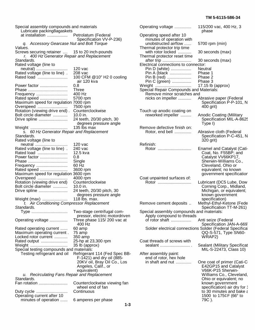
Special assembly compounds and materialsLubricate packing8agasketsat installation ................. Petrolatum (Federal
Specification VV-P-236)q. Accessory Gearcase Nut and Bolt Torque
Values.Screws securing retainer .... 15 to 20 inch-pounds
r. 400 Hz Generator Repair and ReplacementStandards.Rated voltage (line to
neutral) .......................... 120 vacRated voltage (line to line) . 208 vacRated load ......................... 100 CFM @10" H2 0 cooling
air 120 kvaPower factor ....................... 0.8Phase ................................. ThreeFrequency .......................... 400 HzRated speed ....................... 5700 rpmMaximum speed for regulation 7000 rpmOverspeed ......................... 7500 rpmRotation (viewing drive end) . CounterclockwiseBolt circle diameter ............ 10.0 in.Drive spline ........................ 24 teeth, 20/30 pitch, 30
degrees pressure angleWeight ............................... 135 lbs max
s. 60 Hz Generator Repair and ReplacementStandards.Rated voltage (line to
neutral ........................... 120 vacRated voltage (line to line) . 240 vacRated load ......................... 12.5 kvaPower factor ....................... 0.8Phase ................................. SingleFrequency .......................... 60 HzRated speed ....................... 3600 rpmMaximum speed for regulation 3600 rpmOverspeed ......................... 4000 rpmRotation (viewing drive end) CounterclockwiseBolt circle diameter ............ 10.0 in.Drive spline ........................ 24 teeth, 20/30 pitch, 30
degrees pressure angleWeight (max) ..................... 118 lbs. max.
t. Air Conditioning Compressor ReplacementStandards.
Type .............................. Two-stage centrifugal com-pressor, electric motordriven
Operating voltage ............... Three phase 115/ 200 vac at400 Hz
Rated operating current ...... 60 ampMaximum operating current . 75 ampLocked rotor current ........... 350 ampRated output ...................... 25-hp at 23,300 rpmWeight ............................... 35 lb (approx)Special testing compounds and materials:
Testing refrigerant and oil Refrigerant 114 (Fed Spec BB-F-1421) and dry oil (885-20KV oil, Bray Oil Co., LosAngeles, Calif., orequivalent)
u. Recirculating Fans Repair and ReplacementStandards.Fan rotation ........................ Counterclockwise viewing fan
wheel end of fanDuty cycle .......................... ContinuousOperating current after 10
minutes of operation ...... 6 amperes per phase
Operating voltage .............. 115/200 vac, 400 Hz, 3phase
Operating speed after 10minutes of operation withunobstructed airflow ...... 5700 rpm (min)
Thermal protector trip timewith rotor locked ........... 30 seconds (max)
Thermal protector reset timeafter trip ........................ 30 seconds (max)
Electrical connections to connector:Pin D (white) ................. NeutralPin A (black .................. Phase 1Pin B (red) .................... Phase 2Pin C (green) ................ Phase 3
Weight .............................. 17.15 lb (approx)Special Repair Compounds and Materials:
Remove minor scratches andnicks on impeller ........... Abrasive paper (Federal
Specification P-P-101, No.400 grit)
Touch up anodic coating onreworked impeller ......... Anodic Coating (Military
Specification MIL-A-8625,Type I)
Remove defective finish on:Rotor, end bell .............. Abrasive cloth (Federal
Specification P-C-451, No.320 grit)
Refinish:Rotor ............................ Enamel and Catalyst (Cati-
Coat, No. F55BP; andCatalyst VV66KP17,Sherwin-Williams Co.,Cleveland, Ohio orequivalent; no knowngovernment specification)
Coat unpainted surfaces of:Rotor ............................ Lubricant (DC5 Lube, Dow
Corning Corp., Midland,Michigan, or equivalent; noknown governmentspecification)
Remove cement deposits .. Methyl-Ethyl-Ketone (FederalSpecification TT-M-261)
Special assembly compounds and materials:Apply compound to threadsof rotor shaft ................. Anti seize (Federal
Specification JAN-A-669)Solder electrical connections Solder (Federal Specification
QQ-S-571, Type SN60-WRAP2)
Coat threads of screws withsealant ......................... . Sealant (Military Specification
MIL-S-22473, Class 10)After assembly paint:
end of rotor, hex holein shaft and nut ............. One coat of primer (Cati-Coat
E42GP15 and CatalystV66K-P15 Sherwin-Williams Co., Cleveland,Ohio or equivalent; noknown governmentspecification) air dry for 15to 30 minutes and bake at1500 to 175¢F (66° to79C ).
1-3
TM 5-6115-586-34
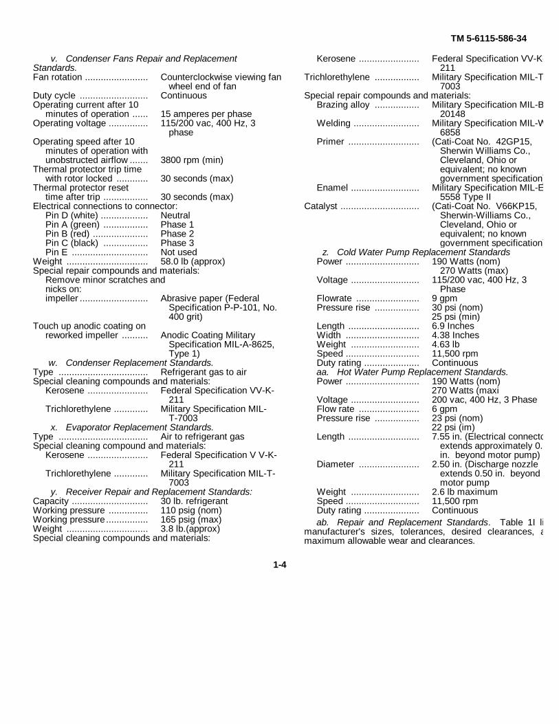
v. Condenser Fans Repair and ReplacementStandards.Fan rotation ........................ Counterclockwise viewing fan
wheel end of fanDuty cycle .......................... ContinuousOperating current after 10
minutes of operation ...... 15 amperes per phaseOperating voltage ............... 115/200 vac, 400 Hz, 3
phaseOperating speed after 10
minutes of operation withunobstructed airflow ....... 3800 rpm (min)
Thermal protector trip timewith rotor locked ............ 30 seconds (max)
Thermal protector resettime after trip ................. 30 seconds (max)
Electrical connections to connector:Pin D (white) .................. NeutralPin A (green) ................. Phase 1Pin B (red) ..................... Phase 2Pin C (black) ................. Phase 3Pin E ............................. Not used
Weight ............................... 58.0 lb (approx)Special repair compounds and materials:
Remove minor scratches andnicks on:impeller .......................... Abrasive paper (Federal
Specification P-P-101, No.400 grit)
Touch up anodic coating onreworked impeller .......... Anodic Coating Military
Specification MIL-A-8625,Type 1)
w. Condenser Replacement Standards.Type .................................. Refrigerant gas to airSpecial cleaning compounds and materials:
Kerosene ....................... Federal Specification VV-K-211
Trichlorethylene ............. Military Specification MIL-T-7003
x. Evaporator Replacement Standards.Type .................................. Air to refrigerant gasSpecial cleaning compound and materials:
Kerosene ....................... Federal Specification V V-K-211
Trichlorethylene ............. Military Specification MIL-T-7003
y. Receiver Repair and Replacement Standards:Capacity ............................. 30 lb. refrigerantWorking pressure ............... 110 psig (nom)Working pressure ................ 165 psig (max)Weight ............................... 3.8 lb.(approx)Special cleaning compounds and materials:
Kerosene ....................... Federal Specification VV-K-211
Trichlorethylene ................. Military Specification MIL-T-7003
Special repair compounds and materials:Brazing alloy ................. Military Specification MIL-B-
20148Welding ......................... Military Specification MIL-W-
6858Primer ........................... (Cati-Coat No. 42GP15,
Sherwin Williams Co.,Cleveland, Ohio orequivalent; no knowngovernment specification)
Enamel .......................... Military Specification MIL-E-5558 Type II
Catalyst .............................. (Cati-Coat No. V66KP15,Sherwin-Williams Co.,Cleveland, Ohio orequivalent; no knowngovernment specification)
z. Cold Water Pump Replacement StandardsPower ............................ 190 Watts (nom)
270 Watts (max)Voltage .......................... 115/200 vac, 400 Hz, 3
PhaseFlowrate ........................ 9 gpmPressure rise ................. 30 psi (nom)
25 psi (min)Length ........................... 6.9 InchesWidth ............................ 4.38 InchesWeight .......................... 4.63 lbSpeed ............................ 11,500 rpmDuty rating ..................... Continuousaa. Hot Water Pump Replacement Standards.Power ............................ 190 Watts (nom)
270 Watts (maxiVoltage .......................... 200 vac, 400 Hz, 3 PhaseFlow rate ....................... 6 gpmPressure rise ................. 23 psi (nom)
22 psi (im)Length ........................... 7.55 in. (Electrical connector
extends approximately 0.50in. beyond motor pump)
Diameter ....................... 2.50 in. (Discharge nozzleextends 0.50 in. beyondmotor pump
Weight .......................... 2.6 lb maximumSpeed ............................ 11,500 rpmDuty rating ..................... Continuousab. Repair and Replacement Standards. Table 1I lists
manufacturer's sizes, tolerances, desired clearances, andmaximum allowable wear and clearances.
1-4
TM 5-6115-586-34
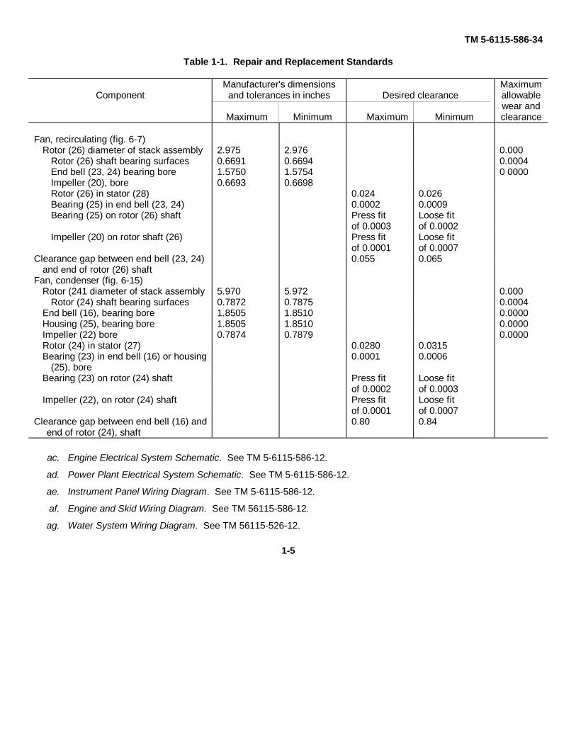
Table 1-1. Repair and Replacement Standards
ComponentManufacturer's dimensions
and tolerances in inches
Maximum Minimum
Desired clearance
Maximum Minimum
Maximumallowablewear andclearance
Fan, recirculating (fig. 6-7)Rotor (26) diameter of stack assembly 2.975 2.976 0.000
Rotor (26) shaft bearing surfaces 0.6691 0.6694 0.0004End bell (23, 24) bearing bore 1.5750 1.5754 0 0000Impeller (20), bore 0.6693 0.6698Rotor (26) in stator (28) 0.024 0.026Bearing (25) in end bell (23, 24) 0.0002 0.0009Bearing (25) on rotor (26) shaft Press fit Loose fit
of 0.0003 of 0.0002Impeller (20) on rotor shaft (26) Press fit Loose fit
of 0.0001 of 0.0007Clearance gap between end bell (23, 24) 0.055 0.065
and end of rotor (26) shaftFan, condenser (fig. 6-15)
Rotor (241 diameter of stack assembly 5.970 5.972 0.000Rotor (24) shaft bearing surfaces 0.7872 0.7875 0.0004
End bell (16), bearing bore 1.8505 1.8510 0.0000Housing (25), bearing bore 1.8505 1.8510 0.0000Impeller (22) bore 0.7874 0.7879 0.0000Rotor (24) in stator (27) 0.0280 0.0315Bearing (23) in end bell (16) or housing 0.0001 0.0006
(25), boreBearing (23) on rotor (24) shaft Press fit Loose fit
of 0.0002 of 0.0003Impeller (22), on rotor (24) shaft Press fit Loose fit
of 0.0001 of 0.0007Clearance gap between end bell (16) and 0.80 0.84
end of rotor (24), shaft
ac. Engine Electrical System Schematic. See TM 5-6115-586-12.
ad. Power Plant Electrical System Schematic. See TM 5-6115-586-12.
ae. Instrument Panel Wiring Diagram. See TM 5-6115-586-12.
af. Engine and Skid Wiring Diagram. See TM 56115-586-12.
ag. Water System Wiring Diagram. See TM 56115-526-12.
1-5
TM 5-6115-586-34
CHAPTER 2
DIRECT SUPPORT AND GENERAL SUPPORTMAINTENANCE INSTRUCTIONS
Section I. REPAIR PARTS, SPECIAL TOOLS AND EQUIPMENT
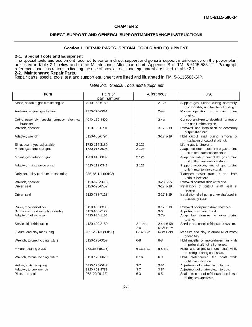
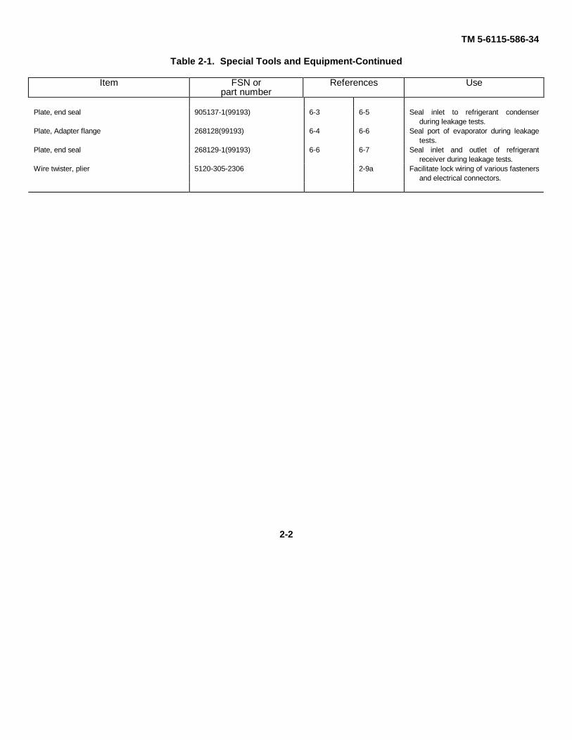
2-1. Special Tools and EquipmentThe special tools and equipment required to perform direct support and general support maintenance on the power plantare listed in table 2-1 below and in the Maintenance Allocation chart, Appendix B of TM 5-6115-586-12. Paragraphreferences and illustrations indicating the use of special tools and equipment are listed in table 2-1.2-2. Maintenance Repair Parts.Repair parts, special tools, test and support equipment are listed and illustrated in TM, 5-6115586-34P.
Table 2-1. Special Tools and Equipment
Item FSN orpart number
References Use
Stand, portable, gas turbine engine 4910-758-6189 2-12b Support gas turbine during assembly,disassembly, and functional testing.
Analyzer, engine, gas turbine 4920-778-6091 2-4a Monitor operation of the gas turbineengine.
Cable assembly, special purpose, electrical,branched
4940-182-4499 2-4a Connect analyzer to electrical harness ofthe gas turbine engine.
Wrench, spanner 5120-793-0701 3-17,3-19 Removal and installation of accessoryoutput shaft nut.
Adapter, wrench 5120-608-6794 3-17,3-19 Hold output shaft during removal orinstallation of output shaft nut.
Sling, beam type, adjustable 1730-115-3189 2-12b Lifting gas turbine unit.Mount, gas turbine engine 1730-015-8005 2-12b Adapt one side mount of the gas turbine
unit to the maintenance stand.Mount, gas turbine engine 1730-015-8002 2-12b Adapt one side mount of the gas turbine
unit to the maintenance stand.Adapter, maintenance stand 4920-118-0346 2-12b Support accessory end of gas turbine
unit in maintenance stand.Dolly set, utility package, transporting 285186-1-1 (99193) Transport power plant to and from
various locations.Wrench, spanner 5120-320-9613 3-23,3-25 Removal or installation of tailpipe.Driver, seal 5120-525-8557 3-17,3-19 Installation of output shaft seal in
retainer.Driver, seal 5120-733-7113 3-17,3-19 Installation of oil pump drive shaft seal in
accessory case.
Puller, mechanical seal 5120-608-8239 3-17,3-19 Removal of oil pump drive shaft seal.Screwdriver and wrench assembly 5120-668-6122 3-6 Adjusting fuel control unit.Adapter, fuel atomizer 4920-924-1196 3-7e Adapt fuel atomizer to tester during
testing.Service kit, refrigeration 4130-400-2150 2-1 thru 2-4b, 6-5b, Service and check refrigeration system.
2-4 6-6b, 6-7eFixture, end play measuring 905128-1-1 (99193) 6-14,6-22 6-8d, 6-9d Measure end play in armature of motor
driven fan.Wrench, torque, holding fixture 5120-178-0057 6-8 6-8 Hold impeller of motor-driven fan while
impeller shaft nut is tightened.Fixture, bearing press 272166 (99193) 6-13,6-21 6-8,6-9 Holds and aligns fan rotor shaft while
pressing bearing onto shaft.Wrench, torque, holding fixture 5120-178-0070 6-16 6-9 Hold motor-driven fan shaft while
tightening shaft nut.Holder, clutch torquing 4920-336-0648 3-7 3-5f Adjustment of starter clutch torque.Adapter, torque wrench 5120-608-4756 3-7 3-5f Adjustment of starter clutch torque.Plate, end seal 268129(99193) 6-3 6-5 Seal inlet ports of refrigerant condenser
during leakage tests.
2-1
TM 5-6115-586-34
Table 2-1. Special Tools and Equipment-Continued
Item FSN orpart number
References Use
Plate, end seal 905137-1(99193) 6-3 6-5 Seal inlet to refrigerant condenserduring leakage tests.
Plate, Adapter flange 268128(99193) 6-4 6-6 Seal port of evaporator during leakagetests.
Plate, end seal 268129-1(99193) 6-6 6-7 Seal inlet and outlet of refrigerantreceiver during leakage tests.
Wire twister, plier 5120-305-2306 2-9a Facilitate lock wiring of various fastenersand electrical connectors.
2-2
TM 5-6115-586-34
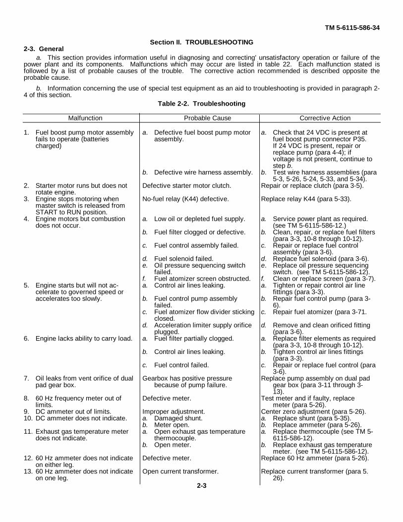
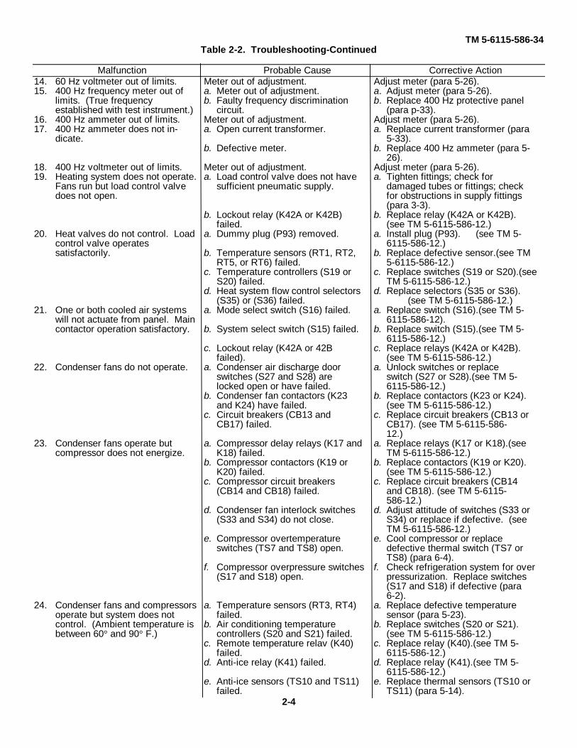
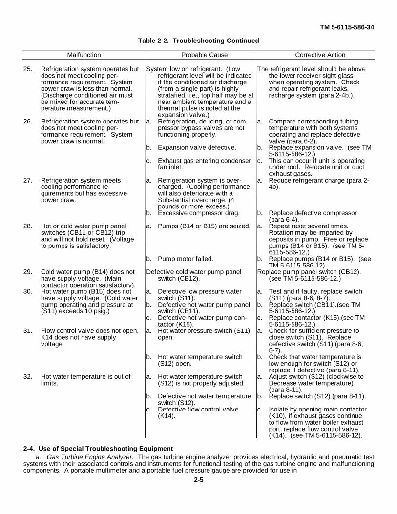
Section II. TROUBLESHOOTING2-3. General
a. This section provides information useful in diagnosing and correcting' unsatisfactory operation or failure of thepower plant and its components. Malfunctions which may occur are listed in table 22. Each malfunction stated isfollowed by a list of probable causes of the trouble. The corrective action recommended is described opposite theprobable cause.
b. Information concerning the use of special test equipment as an aid to troubleshooting is provided in paragraph 2-4 of this section.
Table 2-2. Troubleshooting
Malfunction Probable Cause Corrective Action
1. Fuel boost pump motor assembly a. Defective fuel boost pump motor a. Check that 24 VDC is present atfails to operate (batteries assembly. fuel boost pump connector P35.charged) If 24 VDC is present, repair or
replace pump (para 4-4); ifvoltage is not present, continue tostep b.
b. Defective wire harness assembly. b. Test wire harness assemblies (para5-3, 5-26, 5-24, 5-33, and 5-34).
2. Starter motor runs but does not Defective starter motor clutch. Repair or replace clutch (para 3-5).rotate engine.
3. Engine stops motoring when No-fuel relay (K44) defective. Replace relay K44 (para 5-33).master switch is released fromSTART to RUN position.
4. Engine motors but combustion a. Low oil or depleted fuel supply. a. Service power plant as required.does not occur. (see TM 5-6115-586-12.)
b. Fuel filter clogged or defective. b. Clean, repair, or replace fuel filters(para 3-3, 10-8 through 10-12).
c. Fuel control assembly failed. c. Repair or replace fuel controlassembly (para 3-6).
d. Fuel solenoid failed. d. Replace fuel solenoid (para 3-6).e. Oil pressure sequencing switch e. Replace oil pressure sequencing
failed. switch. (see TM 5-6115-586-12).f. Fuel atomizer screen obstructed. f. Clean or replace screen (para 3-7).
5. Engine starts but will not ac- a. Control air lines leaking. a. Tighten or repair control air linecelerate to governed speed or fittings (para 3-3).accelerates too slowly. b. Fuel control pump assembly b. Repair fuel control pump (para 3-
failed. 6).c. Fuel atomizer flow divider sticking c. Repair fuel atomizer (para 3-71.
closed.d. Acceleration limiter supply orifice d. Remove and clean orificed fitting
plugged. (para 3-6).6. Engine lacks ability to carry load. a. Fuel filter partially clogged. a. Replace filter elements as required
(para 3-3, 10-8 through 10-12).b. Control air lines leaking. b. Tighten control air lines fittings
(para 3-3).c. Fuel control failed. c. Repair or replace fuel control (para
3-6).7. Oil leaks from vent orifice of dual Gearbox has positive pressure Replace pump assembly on dual pad
pad gear box. because of pump failure. gear box (para 3-11 through 3-13).
8. 60 Hz frequency meter out of Defective meter. Test meter and if faulty, replacelimits. meter (para 5-26).
9. DC ammeter out of limits. Improper adjustment. Center zero adjustment (para 5-26).10. DC ammeter does not indicate. a. Damaged shunt. a. Replace shunt (para 5-35).
b. Meter open. b. Replace ammeter (para 5-26).11. Exhaust gas temperature meter a. Open exhaust gas temperature a. Replace thermocouple (see TM 5-
does not indicate. thermocouple. 6115-586-12).b. Open meter. b. Replace exhaust gas temperature
meter. (see TM 5-6115-586-12).12. 60 Hz ammeter does not indicate Defective meter. Replace 60 Hz ammeter (para 5-26).
on either leg.13. 60 Hz ammeter does not indicate Open current transformer. Replace current transformer (para 5.
on one leg. 26).2-3
TM 5-6115-586-34Table 2-2. Troubleshooting-Continued
Malfunction Probable Cause Corrective Action14. 60 Hz voltmeter out of limits. Meter out of adjustment. Adjust meter (para 5-26).15. 400 Hz frequency meter out of a. Meter out of adjustment. a. Adjust meter (para 5-26).
limits. (True frequency b. Faulty frequency discrimination b. Replace 400 Hz protective panelestablished with test instrument.) circuit. (para p-33).
16. 400 Hz ammeter out of limits. Meter out of adjustment. Adjust meter (para 5-26).17. 400 Hz ammeter does not in- a. Open current transformer. a. Replace current transformer (para
dicate. 5-33).b. Defective meter. b. Replace 400 Hz ammeter (para 5-
26).18. 400 Hz voltmeter out of limits. Meter out of adjustment. Adjust meter (para 5-26).19. Heating system does not operate. a. Load control valve does not have a. Tighten fittings; check for
Fans run but load control valve sufficient pneumatic supply. damaged tubes or fittings; checkdoes not open. for obstructions in supply fittings
(para 3-3).b. Lockout relay (K42A or K42B) b. Replace relay (K42A or K42B).
failed. (see TM 5-6115-586-12.)20. Heat valves do not control. Load a. Dummy plug (P93) removed. a. Install plug (P93). (see TM 5-
control valve operates 6115-586-12.)satisfactorily. b. Temperature sensors (RT1, RT2, b. Replace defective sensor.(see TM
RT5, or RT6) failed. 5-6115-586-12.)c. Temperature controllers (S19 or c. Replace switches (S19 or S20).(see
S20) failed. TM 5-6115-586-12.)d. Heat system flow control selectors d. Replace selectors (S35 or S36).
(S35) or (S36) failed. (see TM 5-6115-586-12.)21. One or both cooled air systems a. Mode select switch (S16) failed. a. Replace switch (S16).(see TM 5-
will not actuate from panel. Main 6115-586-12).contactor operation satisfactory. b. System select switch (S15) failed. b. Replace switch (S15).(see TM 5-
6115-586-12.)c. Lockout relay (K42A or 42B c. Replace relays (K42A or K42B).
failed). (see TM 5-6115-586-12.)22. Condenser fans do not operate. a. Condenser air discharge door a. Unlock switches or replace
switches (S27 and S28) are switch (S27 or S28).(see TM 5-locked open or have failed. 6115-586-12.)
b. Condenser fan contactors (K23 b. Replace contactors (K23 or K24).and K24) have failed. (see TM 5-6115-586-12.)
c. Circuit breakers (CB13 and c. Replace circuit breakers (CB13 orCB17) failed. CB17). (see TM 5-6115-586-
12.)23. Condenser fans operate but a. Compressor delay relays (K17 and a. Replace relays (K17 or K18).(see
compressor does not energize. K18) failed. TM 5-6115-586-12.)b. Compressor contactors (K19 or b. Replace contactors (K19 or K20).
K20) failed. (see TM 5-6115-586-12.)c. Compressor circuit breakers c. Replace circuit breakers (CB14
(CB14 and CB18) failed. and CB18). (see TM 5-6115-586-12.)
d. Condenser fan interlock switches d. Adjust attitude of switches (S33 or(S33 and S34) do not close. S34) or replace if defective. (see
TM 5-6115-586-12.)e. Compressor overtemperature e. Cool compressor or replace
switches (TS7 and TS8) open. defective thermal switch (TS7 orTS8) (para 6-4).
f. Compressor overpressure switches f. Check refrigeration system for over(S17 and S18) open. pressurization. Replace switches
(S17 and S18) if defective (para6-2).
24. Condenser fans and compressors a. Temperature sensors (RT3, RT4) a. Replace defective temperatureoperate but system does not failed. sensor (para 5-23).control. (Ambient temperature is b. Air conditioning temperature b. Replace switches (S20 or S21).between 60° and 90° F.) controllers (S20 and S21) failed. (see TM 5-6115-586-12.)
c. Remote temperature relav (K40) c. Replace relay (K40).(see TM 5-failed. 6115-586-12.)
d. Anti-ice relay (K41) failed. d. Replace relay (K41).(see TM 5-6115-586-12.)
e. Anti-ice sensors (TS10 and TS11) e. Replace thermal sensors (TS10 orfailed. TS11) (para 5-14).
2-4
TM 5-6115-586-34
Table 2-2. Troubleshooting-Continued
Malfunction Probable Cause Corrective Action
25. Refrigeration system operates but System low on refrigerant. (Low The refrigerant level should be abovedoes not meet cooling per- refrigerant level will be indicated the lower receiver sight glassformance requirement. System if the conditioned air discharge when operating system. Checkpower draw is less than normal. (from a single part) is highly and repair refrigerant leaks,(Discharge conditioned air must stratafied, i.e., top half may be at recharge system (para 2-4b.).be mixed for accurate tem- near ambient temperature and aperature measurement.) thermal pulse is noted at the
expansion valve.)26. Refrigeration system operates but a. Refrigeration, de-icing, or com- a. Compare corresponding tubing
does not meet cooling per- pressor bypass valves are not temperature with both systemsformance requirement. System functioning properly. operating and replace defectivepower draw is normal. valve (para.6-2).
b. Expansion valve defective. b. Replace expansion valve. (see TM5-6115-586-12.)
c. Exhaust gas entering condenser c. This can occur if unit is operatingfan inlet. under roof. Relocate unit or duct
exhaust gases.27. Refrigeration system meets a. Refrigeration system is over- a. Reduce refrigerant charge (para 2-
cooling performance re- charged. (Cooling performance 4b).quirements but has excessive will also deteriorate with apower draw. Substantial overcharge, (4
pounds or more excess.)b. Excessive compressor drag. b. Replace defective compressor
(para 6-4).28. Hot or cold water pump panel a. Pumps (B14 or B15) are seized. a. Repeat reset several times.
switches (CB11 or CB12) trip Rotation may be imparied byand will not hold reset. (Voltage deposits in pump. Free or replaceto pumps is satisfactory. pumps (B14 or B15). (see TM 5-
6115-586-12.)b. Pump motor failed. b. Replace pumps (B14 or B15). (see
TM 5-6115-586-12).29. Cold water pump (B14) does not Defective cold water pump panel Replace pump panel switch (CB12).
have supply voltage. (Main switch (CB12). (see TM 5-6115-586-12.)contactor operation satisfactory).
30. Hot water pump (B15) does not a. Defective low pressure water a. Test and if faulty, replace switchhave supply voltage. (Cold water switch (S11). (S11) (para 8-6, 8-7).pump operating and pressure at b. Defective hot water pump panel b. Replace switch (CB11).(see TM(S11) exceeds 10 psig.) switch (CB11). 5-6115-586-12.)
c. Defective hot water pump con- c. Replace contactor (K15).(see TMtactor (K15). 5-6115-586-12.)
31. Flow control valve does not open. a. Hot water pressure switch (S11) a. Check for sufficient pressure toK14 does not have supply open. close switch (S11). Replacevoltage. defective switch (S11) (para 8-6,
8-7).b. Hot water temperature switch b. Check that water temperature is
(S12) open. low enough for switch (S12) orreplace if defective (para 8-11).
32. Hot water temperature is out of a. Hot water temperature switch a. Adjust switch (S12) (clockwise tolimits. (S12) is not properly adjusted. Decrease water temperature)
(para 8-11).b. Defective hot water temperature b. Replace switch (S12) (para 8-11).
switch (S12).c. Defective flow control valve c. Isolate by opening main contactor
(K14). (K10), if exhaust gases continueto flow from water boiler exhaustport, replace flow control valve(K14). (see TM 5-6115-586-12).
2-4. Use of Special Troubleshooting Equipmenta. Gas Turbine Engine Analyzer. The gas turbine engine analyzer provides electrical, hydraulic and pneumatic test
systems with their associated controls and instruments for functional testing of the gas turbine engine and malfunctioningcomponents. A portable multimeter and a portable fuel pressure gauge are provided for use in
2-5
TM 5-6115-586-34
troubleshooting checks at various components on theengine. A Special Purpose Electrical Branched CableAssembly and Analyzer Hose Kit are used to connect thetest systems of the analyzer to the engine. Refer to TM5-6115-586-12 for instructions on connecting the gasturbine engine analyzer to the power plant and theprocedures to follow for performing static checks andfunctional tests.
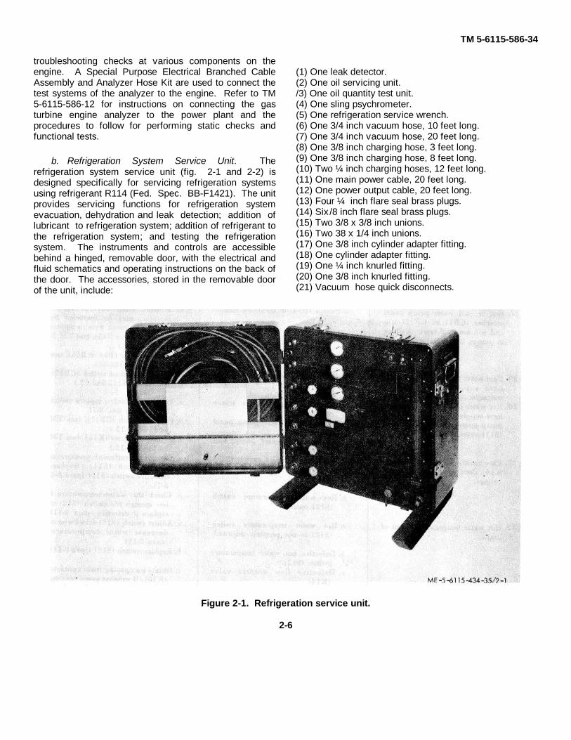
b. Refrigeration System Service Unit. Therefrigeration system service unit (fig. 2-1 and 2-2) isdesigned specifically for servicing refrigeration systemsusing refrigerant R114 (Fed. Spec. BB-F1421). The unitprovides servicing functions for refrigeration systemevacuation, dehydration and leak detection; addition oflubricant to refrigeration system; addition of refrigerant tothe refrigeration system; and testing the refrigerationsystem. The instruments and controls are accessiblebehind a hinged, removable door, with the electrical andfluid schematics and operating instructions on the back ofthe door. The accessories, stored in the removable doorof the unit, include:
(1) One leak detector.(2) One oil servicing unit./3) One oil quantity test unit.(4) One sling psychrometer.(5) One refrigeration service wrench.(6) One 3/4 inch vacuum hose, 10 feet long.(7) One 3/4 inch vacuum hose, 20 feet long.(8) One 3/8 inch charging hose, 3 feet long.(9) One 3/8 inch charging hose, 8 feet long.(10) Two ¼ inch charging hoses, 12 feet long.(11) One main power cable, 20 feet long.(12) One power output cable, 20 feet long.(13) Four ¼ inch flare seal brass plugs.(14) Six/8 inch flare seal brass plugs.(15) Two 3/8 x 3/8 inch unions.(16) Two 38 x 1/4 inch unions.(17) One 3/8 inch cylinder adapter fitting.(18) One cylinder adapter fitting.(19) One ¼ inch knurled fitting.(20) One 3/8 inch knurled fitting.(21) Vacuum hose quick disconnects.
Figure 2-1. Refrigeration service unit.
2-6
TM 5-6115-586-34
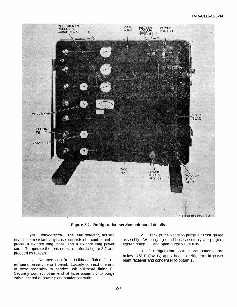
Figure 2-2. Refrigeration service unit panel details.
(a) Leak-detector. The leak detector, housedin a shock-resistant vinyl case, consists of a control unit, aprobe, a six foot long, hose, and a six foot long powercord. To operate the leak-detector, refer to figure 2-2 andproceed as follows.
1. Remove cap from bulkhead fitting F1 onrefrigeration service unit panel. Loosely connect one endof hose assembly to service unit bulkhead fitting Fl.Securely connect other end of hose assembly to purgevalve located at power plant condenser outlet.
2. Crack purge valve to purge air from gaugeassembly. When gauge and hose assembly are purged,tighten fitting F 1 and open purge valve fully.
3. If refrigeration system components arebelow 75° F (24° C) apply heat to refrigerant in powerplant receiver and condenser to obtain 15
2-7
TM 5-6115-586-34
psig minimum pressure reading on gauge GA1. Ifpressure does not increase to 15 psig minimum chargerefrigeration system (para (c) below).
4. If gauge GAI indicates 15 psig, or more,proceed with leak check as outlined in steps 5 through 10.
NoteScrew is for shipping and storagepurposes. Replace screw afterusing detector.5. Remove screw from cap on reference leak
and allow 15 minutes (minimum) for leak rate to stabilize.
6. Connect power cord to power supply outleton service unit.
NoteContamination of the testing areamay cause erratic operation of theleak-detector. Contamination canoccur when the leak in therefrigeration system is very largeand where there is little or noventilation in the testing area.Contamination may also occurwhere excessive amounts ofrefrigerant gases are used. Theleak-detector cannot differentiatebetween atmosphericcontamination and a possible leak.Also, in a highly contaminated area,the flash rate will be unstable, andit will be impossible to adjust thebalance control. Under theseconditions leak detection would notbe possible. A contaminatedcondition can be greatly reducedby ventilating the area or isolatingthe area to be checked.
WarningDo not use leak detector in anexplosive or combustibleatmosphere. Ambient atmosphereis drawn through the probe andover the element which operates atapproximately 1800° F (982° C).The resulting combination of hightemperature and an explosive orcombustible atmosphere maycause an explosion resulting insevere injury or death to personneland damage to equipment.
Caution
Do not attempt to operate the leak-detector at voltages other thanthose specified on the rating platesince damage to the detector mayresult.
CautionDo not place probe in a stream ofrefrigerant and do not blowcigarette smoke into the probesince either will drastically shortenelement life.
NoteVariations in line voltage maycause erratic operation of the leakdetector resulting in reactionssimilar to those for atmosphericcontamination. If voltage variationis suspected, utilize a voltagestabilizing device. Note. If the airflow ball does not rise, tap theprobe tip lightly to make sure ball isnot sticking. If ball still does notrise, replace detector.
7. Check for sufficient air flow by pointing tipof probe downward and observing air flow ball in probe. Ifair flow is correct, air flow ball will rise and float above tipof probe.
8. Place sensitivity switch in either HIGH orLOW position.
9. Adjust flashing rate of lamp in probe byrotating balance control knob until lamp just ceases toflash.
10. Hold probe as closely as possible to thearea being checked and move tip of probe approximatelyone inch per second along seams or joints suspected ofleaking. When a leak is located, the lamp in probe willflash as long as probe is held at the leak.
(b) Evacuation procedure. To evacuate the powerplant refrigeration system, refer to figure 2-3 and 2-4 andproceed as follows:
1. Open service valve on power plantrefrigerant receiver and compressor suction purge valveon compressor, allowing liquid refrigerant to vent fromsystem.
2. When venting stops, attach vacuum hose(ten feet in length) to bulkhead fitting F5 on service unitand to valve on power plant refrigerant receiver as shownin figure 2-3.
2-8
TM 5-6115-586-34
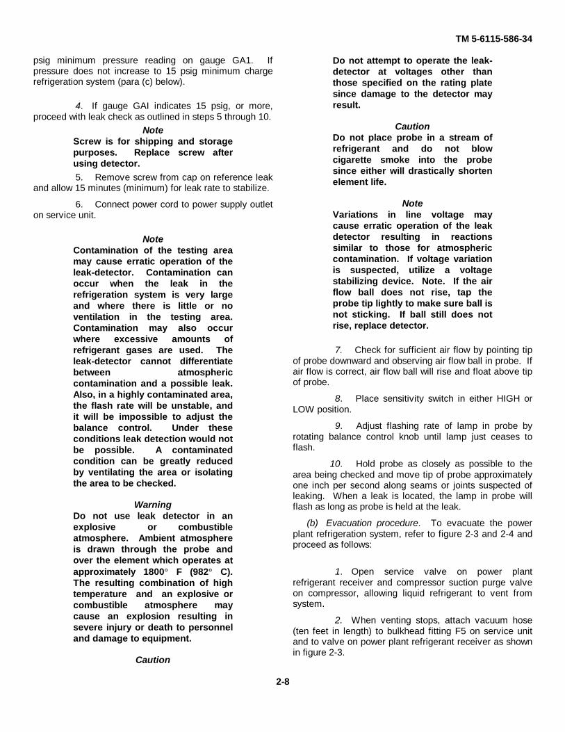
Figure 2-3. service unit connected to power plant.
3. Attach vacuum hose (20 feet in length) tofitting F4 on service unit and to power plant compressorsuction purge valve.
4. Open valve V4 on service unit.
5. Open gas ballast valve (fig. 2-4) on top ofvacuum pump on service unit.
6. Place power switch on service unit (fig. 2-2) in ON position and place heater vacuum pump switchon service unit in VAC PUMP position.
NoteClose valve V4 on service unit toobtain accurate measurement ofpressure in refrigeration system onvacuum gauge GA4. If pressure of
200 microns of Mercury absolutecannot be obtained or held for twohours, leakage in refrigerationsystem is indicated. Check for leak(para (a) above 1.
7. Operate vacuum pump and evacuaterefrigeration system to a pressure of 200 micronsMercury, absolute, as indicated on vacuum gauge GA4.Maintain pressure of 200 microns, or less, for a minimumof two hours.
8. Close service valve on power plantrefrigerant receiver and close compressor suction purgevalve on power plant compressor.
2-9
TM 5-6115-586-34
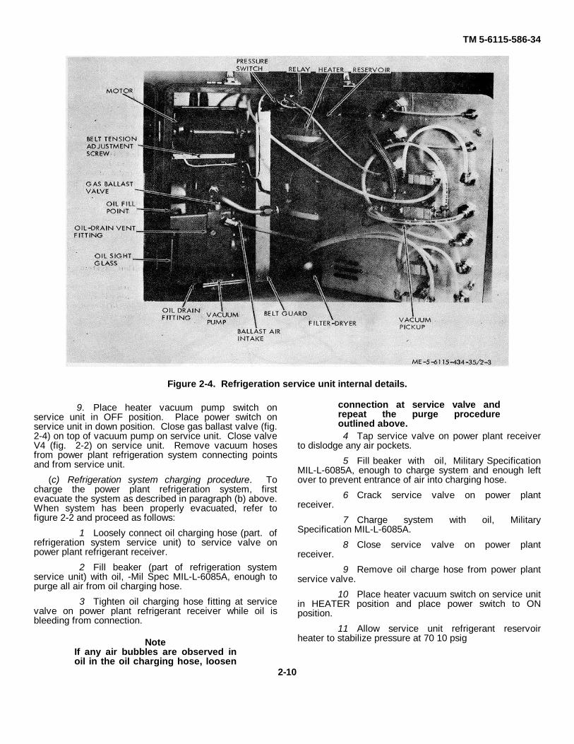
Figure 2-4. Refrigeration service unit internal details.
9. Place heater vacuum pump switch onservice unit in OFF position. Place power switch onservice unit in down position. Close gas ballast valve (fig.2-4) on top of vacuum pump on service unit. Close valveV4 (fig. 2-2) on service unit. Remove vacuum hosesfrom power plant refrigeration system connecting pointsand from service unit.
(c) Refrigeration system charging procedure. Tocharge the power plant refrigeration system, firstevacuate the system as described in paragraph (b) above.When system has been properly evacuated, refer tofigure 2-2 and proceed as follows:
1 Loosely connect oil charging hose (part. ofrefrigeration system service unit) to service valve onpower plant refrigerant receiver.
2 Fill beaker (part of refrigeration systemservice unit) with oil, -Mil Spec MIL-L-6085A, enough topurge all air from oil charging hose.
3 Tighten oil charging hose fitting at servicevalve on power plant refrigerant receiver while oil isbleeding from connection.
NoteIf any air bubbles are observed inoil in the oil charging hose, loosen
connection at service valve andrepeat the purge procedureoutlined above.4 Tap service valve on power plant receiver
to dislodge any air pockets.
5 Fill beaker with oil, Military SpecificationMIL-L-6085A, enough to charge system and enough leftover to prevent entrance of air into charging hose.
6 Crack service valve on power plantreceiver.
7 Charge system with oil, MilitarySpecification MIL-L-6085A.
8 Close service valve on power plantreceiver.
9 Remove oil charge hose from power plantservice valve.
10 Place heater vacuum switch on service unitin HEATER position and place power switch to ONposition.
11 Allow service unit refrigerant reservoirheater to stabilize pressure at 70 10 psig
2-10
TM 5-6115-586-34
as indicated on refrigerant pressure gauge GA3 onservice unit.
12. Loosely connect refrigerant charging hose toservice valve on power plant refrigerant receiver and tofitting F6 on service unit.
13. Check valve V6 on service unit and allowrefrigerant to purge all air from charging hose. Tightenhose connection at service valve while liquid refrigerant ispurging from connection.
14. Fully open valve V6 and fully open service valve.Charge system with refrigerant.
15. Close valve V6 on service unit and service valveon power plant receiver. Remove charging hose andreplace protective caps. Check service valve for leakage(para (a)) above.
d. Checking oil quantity in refrigeration system. Tocheck the oil quantity in the power plant refrigerationsystem refer to figure 2-2 and proceed as follows:
1. Operate refrigeration system according tooperating procedure as described in TM 5-6115586-12 forfifteen minutes to thoroughly mix the refrigerant with theoil.
2. Connect refrigerant charging hose to servicevalve on power plant refrigerant receiver.
WarningDo not hold oil-quantity checkbeaker without gloves or cloth toprotect hands from cold refrigerant.
3. Crack service valve and flow 100 cc refrigerant-oil mixture into oil-quantity-check beaker (part ofrefrigeration system service unit). Close service valve.
4. Place beaker in a warm place and allowrefrigerant to boil off.
5. Quantity of oil remaining in beaker afterrefrigerant has boiled off shall be one cc.
(e) Operation to add oil to refrigeration system. Toadd oil to the power plant refrigeration system, refer tofigure 2-2 and proceed as follows.
1. Connect oil charging hose to the power plantcompressor suction purge valve.
2. Operate refrigeration system as described in TM5-6115-586-12 for fifteen minutes to thoroughly mix therefrigerant and oil.
3. Purge oil charge line and add oil to the system asdescribed in paragraph (c), steps 1 through 9 above.
(f) Operation to remove oil from refrigeration system.If quantity of oil in refrigeration system is too great, referto figure 2-2 and proceed as follows.
1. Operate refrigeration system as described in TM5-6115-586-12 for fifteen minutes to thoroughly mix therefrigerant with the oil.
2. Shut off refrigeration system and evacuatesystem. (para (b) above. ).
3. Charge system (para (c) above), omitting oilcharging procedure, steps 1 through 9.
4. Recheck oil level, (para (d)above), and add oil, ifnecessary (para (e) above).
Section III. GENERAL MAINTENANCE
2-5. Power Plant Test Instructionsa. General. The following test instructions are provided to test the operation of the power plant as a unit both
as an initial test to indicate the extent of repairs required and as a final test to establish serviceability of the power plantfollowing repairs.
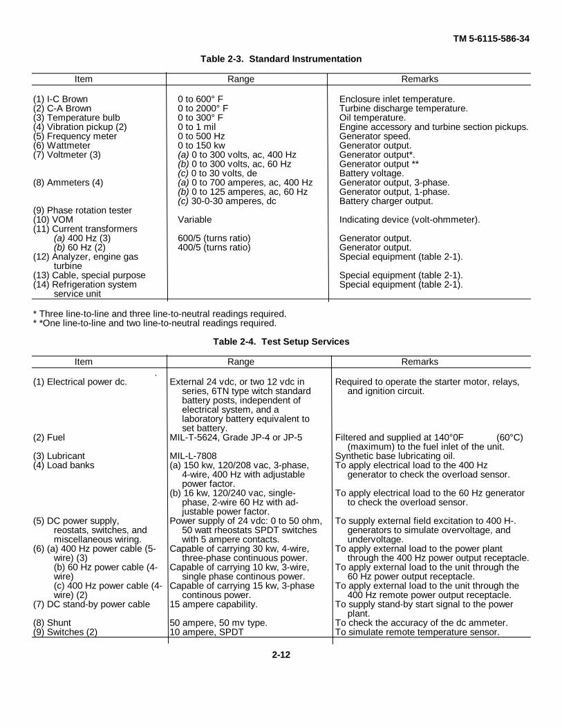
b. Test Connections. Standard instrumentation shall be provided to measure all data shown on the datasheet. All instrumentation shall have been calibrated. Standard instrumentation required is listed in table 2-3. Test set-up services required is listed in table 2-4. Record all test data during testing.
c. Precautions During Testing. Shut down the power plant immediately if any of the operating limits areexceeded or if any malfunction occurs that might result in further damage to components if testing was continued.Determine the cause and take corrective action before proceeding with tests. Power plant operating limits are providedin tables 2-5 and 2-6.
2-11
TM 5-6115-586-34
Table 2-3. Standard Instrumentation
Item Range Remarks
(1) I-C Brown 0 to 600° F Enclosure inlet temperature.(2) C-A Brown 0 to 2000° F Turbine discharge temperature.(3) Temperature bulb 0 to 300° F Oil temperature.(4) Vibration pickup (2) 0 to 1 mil Engine accessory and turbine section pickups.(5) Frequency meter 0 to 500 Hz Generator speed.(6) Wattmeter 0 to 150 kw Generator output.(7) Voltmeter (3) (a) 0 to 300 volts, ac, 400 Hz Generator output*.
(b) 0 to 300 volts, ac, 60 Hz Generator output **(c) 0 to 30 volts, de Battery voltage.
(8) Ammeters (4) (a) 0 to 700 amperes, ac, 400 Hz Generator output, 3-phase.(b) 0 to 125 amperes, ac, 60 Hz Generator output, 1-phase.(c) 30-0-30 amperes, dc Battery charger output.
(9) Phase rotation tester(10) VOM Variable Indicating device (volt-ohmmeter).(11) Current transformers
(a) 400 Hz (3) 600/5 (turns ratio) Generator output.(b) 60 Hz (2) 400/5 (turns ratio) Generator output.
(12) Analyzer, engine gas Special equipment (table 2-1).turbine
(13) Cable, special purpose Special equipment (table 2-1).(14) Refrigeration system Special equipment (table 2-1).
service unit
* Three line-to-line and three line-to-neutral readings required.* *One line-to-line and two line-to-neutral readings required.
Table 2-4. Test Setup Services
Item Range Remarks
(1) Electrical power dc. External 24 vdc, or two 12 vdc in Required to operate the starter motor, relays,series, 6TN type witch standard and ignition circuit.battery posts, independent ofelectrical system, and alaboratory battery equivalent toset battery.
(2) Fuel MIL-T-5624, Grade JP-4 or JP-5 Filtered and supplied at 140°0F (60°C)(maximum) to the fuel inlet of the unit.
(3) Lubricant MIL-L-7808 Synthetic base lubricating oil.(4) Load banks (a) 150 kw, 120/208 vac, 3-phase, To apply electrical load to the 400 Hz
4-wire, 400 Hz with adjustable generator to check the overload sensor.power factor.
(b) 16 kw, 120/240 vac, single- To apply electrical load to the 60 Hz generatorphase, 2-wire 60 Hz with ad- to check the overload sensor.justable power factor.
(5) DC power supply, Power supply of 24 vdc: 0 to 50 ohm, To supply external field excitation to 400 H-.reostats, switches, and 50 watt rheostats SPDT switches generators to simulate overvoltage, andmiscellaneous wiring. with 5 ampere contacts. undervoltage.
(6) (a) 400 Hz power cable (5- Capable of carrying 30 kw, 4-wire, To apply external load to the power plantwire) (3) three-phase continuous power. through the 400 Hz power output receptacle.(b) 60 Hz power cable (4- Capable of carrying 10 kw, 3-wire, To apply external load to the unit through thewire) single phase continous power. 60 Hz power output receptacle.(c) 400 Hz power cable (4- Capable of carrying 15 kw, 3-phase To apply external load to the unit through thewire) (2) continous power. 400 Hz remote power output receptacle.
(7) DC stand-by power cable 15 ampere capability. To supply stand-by start signal to the powerplant.
(8) Shunt 50 ampere, 50 mv type. To check the accuracy of the dc ammeter.(9) Switches (2) 10 ampere, SPDT To simulate remote temperature sensor.
2-12
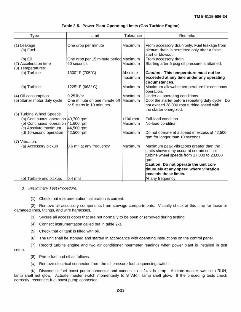
TM 5-6115-586-34
Table 2-5. Power Plant Operating Limits (Gas Turbine Engine)
Type Limit Tolerance Remarks
(1) Leakage One drop per minute Maximum From accessory drain only. Fuel leakage from(a) Fuel plenum drain is permitted only after a false
start or blowout.(b) Oil One drop per 15 minute period Maximum From accessory drain.
(2) Acceleration time 60 seconds Maximum Starting after 5 psig oil pressure is attained.(3) Temperatures:
(a) Turbine 1300° F (705°C) Absolute Caution: This temperature must not bemaximum exceeded at any time under any operating
circumstances.(b) Turbine 1225° F (663° C) Maximum Maximum allowable temperature for continous
operation.(4) Oil consumption 0.25 lb/hr Maximum Under all operating conditions.(5) Starter motor duty cycle One minute on one minute off Maximum Cool the starter before repeating duty cycle. Do
or 5 starts in 10 minutes. not exceed 28,000 rpm turbine speed withthe starter energized.
(6) Turbine Wheel Speeds(a) Continuous operation 40,700 rpm ±100 rpm Full-load condition.(b) Continuous operation 41,600 rpm Maximum No-load condition.(c) Absolute maximum 44,500 rpm(d) 10-second operation 42,500 rpm Maximum Do not operate at a speed in excess of 42,500
rpm for longer than 10 seconds.(7) Vibration:
(a) Accessory pickup 0.6 mil at any frequency Maximum Maximum peak vibrations greater than thelimits shown may occur at certain criticalturbine wheel speeds from 17.000 to 23,000rpm.Caution: Do not operate the unit con-tinuously at any speed where vibrationexceeds these limits.
(b) Turbine end pickup. 0.4 mils At any frequency.
d. Preliminary Test Procedure.
(1) Check that instrumentation calibration is current.
(2) Remove all accessory components from stowage compartments. Visually check at this time for loose ordamaged lines, fittings, and wire harnesses.
(3) Secure all access doors that are not normally to be open or removed during testing.
(4) Connect instrumentation called out in table 2-3.
(5) Check that oil tank is filled with oil.
(6) The unit shall be stopped and started in accordance with operating instructions on the control panel.
(7) Record turbine engine and two air conditioner hourmeter readings when power plant is installed in testsetup.
(8) Prime fuel and oil as follows:
(a) Remove electrical connector 'from the oil pressure fuel sequencing switch.
(b) Disconnect fuel boost pump connector and connect to a 24 vdc lamp. Acutate master switch to RUN,lamp shall not glow. Actuate master switch momentarily to START, lamp shall glow. If the preceding tests checkcorrectly, reconnect fuel boost pump connector.
2-13
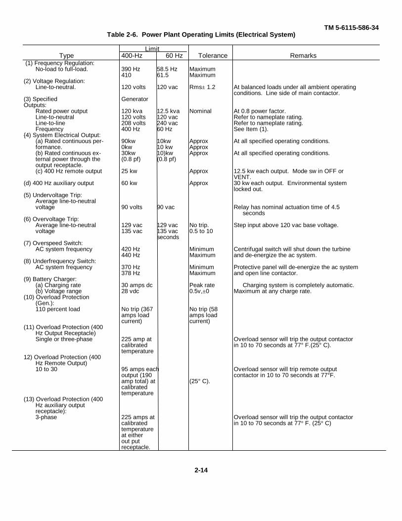
TM 5-6115-586-34Table 2-6. Power Plant Operating Limits (Electrical System)
LimitType 400-Hz 60 Hz Tolerance Remarks
(1) Frequency Regulation:No-load to full-load. 390 Hz 58.5 Hz Maximum
410 61.5 Maximum(2) Voltage Regulation:
Line-to-neutral. 120 volts 120 vac Rms± 1.2 At balanced loads under all ambient operatingconditions. Line side of main contactor.
(3) Specified GeneratorOutputs:
Rated power output 120 kva 12.5 kva Nominal At 0.8 power factor.Line-to-neutral 120 volts 120 vac Refer to nameplate rating.Line-to-line 208 volts 240 vac Refer to nameplate rating.Frequency 400 Hz 60 Hz See Item (1).
{4) System Electrical Output:(a) Rated continuous per- 90kw 10kw Approx At all specified operating conditions.formance. 0kw 10 kw Approx(b) Rated continuous ex- 30kw 10)kw Approx At all specified operating conditions.ternal power through the (0.8 pf) (0.8 pf)output receptacle.(c) 400 Hz remote output 25 kw Approx 12.5 kw each output. Mode sw in OFF or
VENT.(d) 400 Hz auxiliary output 60 kw Approx 30 kw each output. Environmental system
locked out.(5) Undervoltage Trip:
Average line-to-neutralvoltage 90 volts 90 vac Relay has nominal actuation time of 4.5
seconds(6) Overvoltage Trip:
Average line-to-neutral 129 vac 129 vac No trip. Step input above 120 vac base voltage.voltage 135 vac 135 vac 0.5 to 10
seconds(7) Overspeed Switch:
AC system frequency 420 Hz Minimum Centrifugal switch will shut down the turbine440 Hz Maximum and de-energize the ac system.
(8) Underfrequency Switch:AC system frequency 370 Hz Minimum Protective panel will de-energize the ac system
378 Hz Maximum and open line contactor.(9) Battery Charger:
(a) Charging rate 30 amps dc Peak rate Charging system is completely automatic.(b) Voltage range 28 vdc 0.5v,±0 Maximum at any charge rate.
(10) Overload Protection(Gen.):110 percent load No trip (367 No trip (58
amps load amps loadcurrent) current)
(11) Overload Protection (400Hz Output Receptacle)Single or three-phase 225 amp at Overload sensor will trip the output contactor
calibrated in 10 to 70 seconds at 77° F.(25° C).temperature
12) Overload Protection (400Hz Remote Output)10 to 30 95 amps each Overload sensor will trip remote output
output (190 contactor in 10 to 70 seconds at 77°F.amp total) at (25° C).calibratedtemperature
(13) Overload Protection (400Hz auxiliary outputreceptacle):3-phase 225 amps at Overload sensor will trip the output contactor
calibrated in 10 to 70 seconds at 77° F. (25° C)temperatureat eitherout putreceptacle.
2-14
TM 5-6115-586-34
CautionDo not exceed starter motor dutycycle specified in item (5) of table 2-5.
(c) Motor gas turbine engine by means ofstarter until oil pressure gauge on test panel registerspressure.
(d) Reconnect electrical connector to oilpressure switch.
(e) Check unit for fuel and oil leaksimmediately after this operation. If leakage is apparent,correct the difficulty.
e. Instrument Panel Checks.(1) Close the dc circuit breakers and check the
following items for proper operation as specified.
(a) Check panel light for proper operation.Panel light shall come on when switch is actuated in ONposition.
(b) With air intake door in open position, checkfuel boost pump for proper operation. Set MASTERswitch in STOP position. Actuate fuel boost pump bythrowing FUEL BOOST switch to ON position. Pumpshall run. Set the MASTER SWITCH in RUN position.Fuel boost pump shall stop.
(c) With MASTER switch in RUN position,check PRESS-TO-TEST indicator lights. Pressing in oneach light shall cause it to glow. This test indicates onlythat light bulb is functional and not the condition of itsassociated circuit. Replace faulty light bulbs.
NoteIn order to check compressor triplights and remote trip light, unitmust be operating, 400 Hz maincontactor switch must be in CLOSEposition and mode-select switch inOFF position.
(d) Check for proper operation of start interlockof 60 Hz load contactor switch and 400 Hz main contactorswitch. Actuate 60 Hz load contactor switch to CLOSEposition. Actuate MASTER switch to START. The powerplant shall not start. Actuate 60 Hz load contactor switchto OPEN. Repeat this procedure with 400 Hz contactorswitch.
(e) Check for proper operation of batterycharger and ready-to-load light. Close battery chargercircuit breaker. Start power plant. Readyto-load lightshall glow at 95 percent governed speed. Battery chargershall come on when 400 Hz generator voltage builds up.Generator shall reach full voltage at approximately 70percent governed speed.
(2) Run power plant for three minutes at noloadgoverned speed to allow for stabilization and transients.
(3) Check for phase rotation of 400 Hz systemat the following locations.
(a) The 400hz power output receptacles J7 andJ8, located on the power output panel. The phaserotation shall be LI, L2, L3, N: A,B,C,D and E. Pin E isequipment ground.
(b) Disconnect power plug from each of the air-conditioning compressors and check phase rotation. Thephase rotation shall be LI, L2, L3, N: A, B, C and D.
(4) Check generator terminal connections at 60Hz output panel, J5 60 Hz output receptacle and J6 60 Hzoutput receptacle. The connection sequence shall be TI,T2, T3: B, D, C and E is equipment ground and A isemergency 24 vdc, output; T3 is neutral. Voltageindication shall be 240 volts B to D and 120 volts B to Cand D to C.
(5) Check accuracy of the followinginstruments on power plant instrument panel againstcalibrated test instruments. Using external adjust screw,adjust each master to correspond to associated laboratorymeter. Reject and replace any meter that cannot beadjusted within specified limits.
(a) Using the voltage-adjust potentiometer onthe voltage regulator, set C-N voltage at 120 volts (redline). Record C-N voltage indicated on test meter. Errorshall not exceed +/-2 volts. Check A-N and B-N voltage.
(b) Using the voltage-adjust potentiometer onvoltage regulator, set TI-T3 voltage at 120 volts (red line).Record TI-T3 voltage indicated on test meter. Error shallnot exceed +/- 2 volts. Check T2T3 voltage. T2-T3voltage shall be 120 -'2 volts. TI-T3 voltage shall be 120+/-2 volts. Check TiT2 voltage. TI-T2 voltage shall beequal to the sum of T I-T3 and T2-T3 voltage (240 +/- 4volts).
(c) Using a variable-load 0. 8 PF load bank,set up 100 percent readings on instrument panel 60 Hzammeter. Test each leg individually. Record amperageindicated on test meter for leg being tested. Error shallnot exceed +/-3 percent. The 100 percent load is equal to52 amperes per leg when a 120 volt load is applied.
(d) Using a variable load 0. 8 PF load bank,set tp 100 percent readings on instrument panel 400 Hzammeter. Test each phase individually. Recordamperage indicated on the test meter for the phase beingtested. Error shall not exceed +/-3 percent. The 100percent load is equal to 333 amperes per phase.
(e) Regulate engine speed to 390 Hz, 400 Hzand 410 Hz as indicated by the instrument panel 400 Hzfrequency meter. For each of these settings, logfrequency reading. Error shall be within +/-2. 5 Hz.
(f) With 400Hz generator operating at 400 Hz,60 Hz meter should read 60 Hz. Error shall be within 1Hz.
(g) Remove positive lead from unit batterycharger and connect test shunt (50A) in series. Recordinstrument panel meter reading and test meter reading.Error shall not exceed three amperes.
2-15
TM 5-6115-586-34
(h) lnstall thermocouple in boss provided onengine tailpipe section. Cheek tailpipe temperature circuitby using the Brown indicator and unit thermocouple.Adjust so that unit thermocouple reads within +/- 25° F(14° C) of indicator reading.
f. Electrical System Checks. Perform electricalsystem checks as follows:
(1) Operate unit in the following sequence atsteadv-state loads at zero. 100, zero, 50 and 100 percentrated loads of 0.8 PF. Perform test on both 60 Hzgenerator and 400 Hz generator. Log on each data sheetvoltage, frequency and percent load it each load point foreach phase of the 400 Hz generator and for each leg andL-L of the 60 Hz generator.
(2) Perform voltage regulation check (stepload application and removal) as follows.
NoteThe 10 kw, 60 Hz load can beapplied directly through outputreceptacles. To apply 90 kw. 400Hz loads. attach extra power loadsto terminal board on the airconditioning panel. Apply 30 kw topower output and 60 kw to terminalboard connection.
(a) Apply a step load of 10 kw at 0. 8 PF to 0it)Hz generator. Allow voltage to stabilize, then remove 10kw load.
(b) Using a 90 kw at 0. 8 PF load, repeatparagraph f. step (2), (a) above for 400 Hz generator.
(3) Unit shall meet the following electricalrequirements.
(a) Voltage variation shall not exceed 2. 5percent from no-load to full-load as set throughout entireload range and -1 percent at any fixed load.
(b) Upon application or removal of rated loadI10 kw at 0. 8 PF), voltage shall not vary sufficiently tocause generator protective panel to trip generator off theline.
(c) Upon application or removal of 90 kw at 0.8 PF, voltage shall not vary sufficiently to causeprotective panel to trip generator off the line.
(d) Frequency shall remain within limits of +/- 2percent for (0' Liz system and 392 to 408 Hz for 400 Hzsystem for all steady-state load conditions.
(e) Transient-frequency limits for suddenapplication or removal of 10 kw at 0. 8 PF shall be within4+/- 3 percent for 60 Hz system. Transient-frequencylimits for sudden application or removal of 80 kw at 0. 8PF shall be 390 to 410 Hz for the 400 Hz system.
(f) Transient-frequency shall return to andremain within the range of 58 to 62 Hz for 60 Hz system
and 392 to 408 Hz for 400 Hz system within threeseconds.
(4) Check air-intake door interlock switch asfollows.
(a) Attempt a start with air-intake door closed.Unit shall not start.
(b) While operating, press intake door interlockswitch and hold momentarily. Unit shall shut down.
(5) With unit operating and 400 Hz maincontactor switch in OPEN position, actuate 400 Hz outputcontactor switch to CLOSE-RESET and release. Using avolt-ohmeter, set on 300 vac scale, check voltage at J7and J8, 400 Hz output receptacle and across pins A,B,Cand E. There shall be no voltage indicated.
(6) With 400 Hz main contactor switch inOPEN position and air-conditioning control circuit breakerpushed in, rotate ac mode select switch to VENY COOLAND HEAT. In the VENT, COOL AND HEAT Modes,there shall be no power, ac or dc, applied to air-conditioning system. No fan or compressor shall start norshall load control or heating flow-control valves open inthe HEAT mode.
(7) Perform emergency dc output and standbyreceptacle output check as follows:
(a) Using a volt-ohmmeter, set at 50 vdc,check across pin A (+ ) of J5 and J6, 60 Hz outputreceptacle and pin D (-) of J7 and J8, 400 Hz outputreceptacle and also across pin 1 (+ ) and pin 2 (-) of J 1dc standby receptacle. This test can be made whileperforming 400 Hz output overload sensor trip test, or byplacing 400 Hz output contactor switch in center positionwith 400 Hz main contactor closed. When 400 Hz outputcontactor trips, there should be a 24 vdc indicationbetween J5-A and J7-D, J6-A and J8-D and J1-1 and J1-2.
(b) With same meter connection as in (a)above and when performing underfrequency trip check orany of the other protective device checks that trip 400 Hzgenerator, check for voltage indication. Each check pointshall indicate 24 vdc.
(c) With same meter connections as in (a) and(b) above and when performing any of the protectivedevice checks that trip 60 Hz generator, observe metersfor voltage indication. When 60 Hz contactor trips, thereshall be 24 vdc showing on meter attached to pin A of J5or J6.
(8) Place all circuit breakers and switches innormal position for starting and proceed as follows.
(a) Close air-intake door. Reconnect 24 vdc toJ 1. Unit shall not start. Disconnect 24 vdc from J1.
(b) Open air-intake door. Reconnect 24 vdc toJ1. Unit shall start. At 95 percent governed speed, 24vdc signal from J1 shall cease and all contactors shallclose. The 60 Hz and 400 Hz power shall be available atoutput receptacles. With a volt-ohmmeter set at 300 vac,check pins B and C of J5 and J6 and pins C and D of J7and J8.
2-16
(c) After unit reaches governedspeed, actuate switches as indicated below in thesequence as listed.
Master switch to RUN.400 Hz output contactor switch to RESET-CLOSE.60 Hz load contactor switch to CLOSE.400 Hz main contactor to CLOSE.
Unit shall continue to run from unit battery and loadcontactor shall stay closed without interruption of power.
(9) Check unit capability for achievingsuccessful starts with the following battery arrangement.Note. Ascertain unit has started from unit batterybefore performing this test. Disconnect battery withinthe unit. External battery must have a full charge with25.5 vdc minimum.
(a) Connect dc battery cable toexternal battery, with reverse polarity to power outputpanel receptacle. Reverse polarity light shall glow.With battery still connected with reverse polarity,attempt to start unit. Unit shall not start.
(b) Connect dc battery cable toexternal battery with correct polarity. Reverse polaritylight shall not glow and unit shall start.
(c) Connect an external 24 Vdcbattery to power-out panel receptacle with unit batteryconnected. Start unit. External battery voltage must beone volt higher than unit battery.
(10) With unit operating, actuate 400 Hzmain contactor switch to CLOSE and 400 Hz outputswitch to RESET-CLOSE. Push in 400 Hz conveniencereceptacle circuit breaker. Using a volt-ohmmeter set at300 vac, check for voltage at each of the two outlets.Meter shall indicate approximately 120 volts L-N.
(11) With unit operating, actuate 60 Hz loadcontactor switch to CLOSE. Push in 60 Hz conveniencereceptacle circuit breaker. Using a voltohmmeter set at30.0 vac, check for voltage at each of the two outlets.Meter shall indicate approximately 120 volts L-N at eachoutlet.
(12) Connect a zero to 30 vdc voltmeteracross battery terminals. Observe panel 30-0-30ampere ammeter and log indicated readings on datasheet. Log voltage when battery charger is fullycharging (30 amperes) and when battery charger issupplying the unit's rated use. The panel 30-0-30ammeter shall indicate approximately zero amperes.Battery charger is completely automatic and is currentlimited. Charging current shall be limited to 30amperes. Battery charger output voltage shall notexceed 28 volts when carrying full charge or minimumcharge rate. Adjust voltage as required. With correctvoltage set, adjust current boost and taper charge on K-R battery charger to maximum cycle time. Turnadjustment counterclockwise.
(13) With unit operating, actuate 400 Hzmain contactor switch to CLOSE and 400 Hz outputswitch to RESET-CLOSE. Push in water line heating
circuit breaker CB6. Using a voltohmmeter set at 300vac, check for voltage at each of the two water lineheater receptacles J72 and J73 (pin C to pin D). Metershall indicate approximately 120 volts, L-N, at eachreceptacle.
(14) With unit operating and mode-selectswitch in OFF position, actuate 400 Hz main contactorswitch to CLOSE position and proceed as follows.
(a) Actuate remote operation switch toOPERATE-RESET. Check phase rotation at each ofthe remote output receptacles. Phase sequence shallbe L1, L2, L3, N: A, B, C, E and D is +24 vdc. Voltageshall be 120 volts L-N and 24 vdc from pin D andground.
(b) Rotate mode-select switch toVENT position. Vent fans, as set on the vent-selectswitch, shall run. Voltage at remote receptacles shall bethe same as in paragraph f. step ( 14), (a)above.
(c) Rotate mode-select switch toHEAT and COOL. No voltage shall be available at theremote output receptacles.
(d) Where two units are available attest site, attach a 400 Hz auxiliary power output cable toremote power-output receptacle on operating unit toremote input on non-operating unit. Actuate remoteoperation switch on operating unit to OPERATE-RESET, then actuate remote-operation switch on non-operating unit. Vent fans on non-operating unit shalloperate as if unit were operating. Check vent fanoperation through each output.
(e) When two units are not available,remote input can be checked as follows:
1. Connect a 400 Hz auxiliarypower output cable between test box and remote inputreceptacle.
2. Place 400 Hz maincontactor switch in OPEN position.
3. Actuate remote switchlocated on test box by placing it in ON position.
4. Actuate the remoteoperation switch located on control panel to OPERATE-RESET.
5. Place mode-select switch toVENT.
6. Rotate vent-system-selectswitch to each position and check for proper operation ofvent fans.
7. Rotate mode-select switchto HEAT, COOL and OFF. Vent fans shall not operate.
(15) With unit operating and mode-selectswitch in OFF position, actuate 400 Hz main contactorswitch to CLOSE position and proceed as follows.
(a) Actuate Output 1 400 Hz auxiliaryoperation switch to OPERATE-RESET. Check phaserotation at Output 1 receptacle (J101).
2-17
Phase sequence shall be L1, L2, L3, N: A, B, C, D withE as the equipment ground. Voltage shall be 120 voltsline-to-neutral and 208 volts line-to-line.
(b) With Output 1 400 Hz auxiliarypower actuated, the voltage at Output 1 receptacle shallremain the same as noted above and there shall be nopower, ac or de, applied to the no. 1 conditioned airsystem under the following operating conditions.
1. Mode select switch in HEATposition as heat system select switch is rotated topositions 1, 2 and 1 and 2 (no. 2 heated air system shalloperate in position 2 or position 1 and 2).
2. Mode select switch inCOOL position as air conditioning system select switchis rotated to positions 1. 2, and 1 and 2 (no. 2 cooledair system shall operate in position 2 or position 1 and2).
(c) Place output I auxiliary operationswitch in OFF position and actuate output 2 auxiliaryoperation switch to OPERATE-RESET. Check phaserotation at output 2 receptacle (J102). Phase sequenceshall be L1, L2, L3, N: A, B, C, D with E as equipmentground. Voltage shall be 120 volts line-to-neutral and208 volts line-to-line.
(d) With output 2 400 Hz auxiliarypower actuated, the voltage output at output 2receptacle shall remain the same as noted above andthere shall be no power, ac or dc, applied to the no. 2conditioned air system under the following operatingconditions:
1. Mode select switch in HEATposition as heat system select switch is rotated topositions 1, 2, and I and 2 (no. 1 heated air system shalloperate in position 1 or position 1 and 2).
2. Mode select switch inCOOL position as air conditioning system is rotated topositions 1, 2, and 1 and 2 (no. 1 cooled air systemshall operate in position 1 or position 1 and 2).
(e) With both No. 1 and No. 2 400Hz auxiliary operation switches actuated to OPERATE-RESET position, required voltage shall be present atboth Output 1 and Output 2 receptacles and no powershall be applied to either conditioned air system in anyHEAT or COOL mode.
(f) Actuate remote operation switchto OPERATE-RESET. No voltage shall be present ateither of the remote output receptacles (J74 and J75).
(g) With 400 Hz main contactorclosed and remote operation switch, mode-select switchand auxiliary operation switches in OFF position,actuate remote operation switch to OPERATE-RESET.Voltages shall be present at remote output receptacles.Actuate auxiliary operation switch to OPERATE RESET.Voltage shall not be present at remote outputreceptacles but shall be present at auxiliary outputreceptacles.
(h) With the remote operation switch
and the auxiliary switch in the OFF position, rotate themode-select switch to VENT. Actuate the auxiliaryswitch to OPERATE-RESET. The vent fans shouldcontinue to operate and voltage should be present at theauxiliary output receptacles.
(i) Repeat paragraph f, step (15),(f),above, except rotate mode-select switch to HEAT.Complete heating system shall be de-energized (shutoff) and voltage shall be present at auxiliary on outputreceptacles.
(j) Repeat paragraph f, step (15),(f),above, except rotate mode-select switch to COOL.Complete air-conditioning system shall be deenergized(shut-off) and voltage shall be present at auxiliaryoutput receptacles.
g. Protective Device Checks. The followingchecks are to be performed to ensure proper functioningof electrical system protective circuits.
(1) While reading 400 Hz generatorfrequency on a frequency meter, slowly reduce turbinespeed until meter reads 370 Hz by manually bypassingfuel. Then perform test with the EMERGENCYOPERATION switch closed and determine that underfrequency device will not trip 400 Hz generator off theline. Generator shall be tripped off the line whenfrequency drops to 374 ± 4 Hz with EMERGENCYOPERATION switch open.
(2) Observe and record exact speedreading as indicated by frequency meter. Then,operating at no-load, slowly increase turbine speed bymeans of governor adjustment screw until overspeedprotective-device actuates. Do not exceed 44,500 rpm.Use fuel bypass to perform this test. Overspeedprotective device must shut down unit betweengenerator frequencies of 420 and 440 Hz. Repeat testwith EMERGENCY OPERATION switch closed andascertain that switch does not render overspeed switchinoperative. Readjust speed to original frequencyreading.
(3) Both generators shall be operated atno-load and rated speed while performing the followingtests. Ascertain that load contactors are in CLOSEDposition. Refer to paragraph g, step (7) below.
(a) Remove connector from voltageregulator of system being checked. Connect voltageregulator connector to test box. Adjust rheostat untilbase voltage of 120 volts L-N on each generator is setup.
(b) Monitor generator voltage on theload side of contactors to determine voltage at whichprotective panel energizes the GCR and trips loadcontactors.
(c) Adjust generator voltage to 128volts L-N for 30 seconds. Reset to 120 volts L-N.Adjust voltage to 135 volts L-N. Do not exceed 30seconds.
2-18
(d) Immediately after contactors trip,decrease voltage to 120 volts L-N.
(e) Reset generator control relay.Check under voltage protective device by loweringvoltage to 92 volts for 30 seconds. Readjust to 120volts L-N. Decrease to 90 volts L-N. The under voltageprotective device trips generator control relay and de-energizes load contactors.
(f) The 40U Hz overvoltageprotective device shall provide a trip signal on the 400Hz generator when three phase average voltageincreases to 135 volts and remains thus from 0.5 to 10seconds. No trip at 128 volts. The 60 Hz overvoltageincreases to 135 volts and remains there from 0.5 to 10seconds. No trip at 128 volts.
(g) The 400 Hz undervoltage deviceshall provide a trip signal on 400 Hz generator whenthree phase average voltages decrease to 90 volts andremain there for 4.5 seconds, minimum. The 60 Hzundervoltage device shall provide a trip signal whenlowest leg voltage decreases to 90 volts and remainsthere for 4.5 seconds minimum. No trip at 92 volts.
(4) Apply 110 percent or rated three phasebalanced load to 400 Hz generator and 110 percent ofrated single-phase, three-wire, balanced load to 60 Hzgenerator. Repeat this procedure with 150 percentbalanced load. Refer to paragraph g, step (7) below.Line contactor shall open at calibrated temperaturewithin the 30 to 120 seconds at 150 percent. Contactorshall not trip at 110 percent (operate for five minutes).The total air-conditioning system will have to beoperating and external loads will have to be attached topower cable through output connector. The 60 Hzpower can be taken from output receptacle. Obtainmeter readings of generator voltage and current.
Caution: Do not exceed 45 kw on the external400 Hz output connector.
Note. To apply loads required for thistest for 400 Hz generator, extra leads will have to beattached to terminal board on air-conditioning panel.
(5) Apply a three-phase balanced 115ampere load to each of the 400 Hz output powerreceptacles. Overload sensor shall trip at approximately225 amperes within 10 to 70 seconds at calibratedtemperature. The 400 Hz output contactor shall notreset unless reset with contactor switch. The 400 Hzoutput trip light shall glow when 400 Hz output contactortrips.
(6) When performing the protectivedevices check herein, observe contactor trip indicatorlights on unit control panel. Lights shall glow each time400 Hz main contactor or 60 Hz load contactor trips.Actuation of corresponding contactor switch to its resetposition shall extinguish indicator lamp.
(7) When performing one of the protectivepanel trip functions in 60 Hz generating system, actuatecontrol switch to RESET position and hold it there untilreset control trips and remains tripped and ac systembecomes de-energized. Remove simulated fault andagain actuate control. Repeat this procedure for 400 Hzgenerating system. Reset control shall reset only onceafter actuation and shall then trip and remain tripped aslong as the fault exists and control-switch is hold inRESET position. Upon removal of the fault andreactuation of control, the system shall return to normaloperation.
(8) Low oil pressure shutdown check canbe performed at completion of any test that requiresoperation of turbine engine. Disconnect plug from lowoil pressure switch. Turbine engine shall shut down.Reconnect plug to low oil pressure switch. This testchecks continuity of electrical circuit only. This is noindication of switch setting or operation.
(9) Check 400 Hz remote output overloadsensor by applying a three-phase balanced 95 ampereload to each of the remote output receptacles. Overloadsensor shall trip at approximately 190 amperes totalwithin 10 to 70 seconds at calibrated temperature.Remote output contactor shall not be reset unless resetwith remote operation switch. Remote trip light shallglow when remote output contactor trips.
(10) Check 400 Hz auxiliary output overloadsensors by applying a three-phase balanced 225ampere load to each of the auxiliary output receptacles,individually. With overload applied, overload sensorsshall trip at approximately 225 amperes within 10 to 70seconds, at calibrated temperature, without loss ofpower to the other auxiliary output receptacle. The 400Hz auxiliary trip lights shall glow. Tripped outputcontactor shall not reset unless reset with 400 Hzauxiliary operation switch. Acutation of 400 Hz auxiliaryswitches to OPERATE-RESET shall reset trippedcontactor without loss of power to output receptacle.Perform for each output. A delay in resetting ofcontactor will be required to allow overload sensors tocool down.
(11) Check the transient voltage (motorstarting load) as follows.
(a) With 400 Hz generator operatingat no-load, suddenly apply a 240 volts, two per unit, 0.4power factor load on 60 Hz generating system or start a120 volts, two horsepower motor. Do not hold two perunit load on longer than 15 seconds. Voltage shall notdip sufficiently low to cause the protective panel to tripgenerator off the line within the limits of undervoltagetrip.
(b) With 60 Hz generator operatingat no-load and 400 Hz system operating at a steady-state
2-19
three-phase load of 30().0 .kw at 0.8 power factor, applythe additional surge (starting) current demand of thetotal air-conditioning system. Voltage shall not dipsufficiently low to cause protective panel to tripgenerator off the line within limits of the undervoltagetrip.
(12) Generator protective devices shall nottrip generator and load contactor off the line whileundergoing voltage regulation and frequency check andair-intake door interlock switch check. During air-intakedoor interlock test, the protective device will trip 60 Hzgenerator if overload time is exceeded.
h. Air-conditioning Systems. Performoperational checks in accordance with TM 5-6115-586-12.
i. Heating System. Perform operationalchecks in accordance with TM 5-6115-586-12.
j. Hot and Cold Water System. Performoperational checks in accordance with TM 5-6115-586-12.
k. Bleed-Air System. Perform operationalcheck in accordance with TM 5-6115-586-12.
l. Vacuum System. Perform operational checkin accordance with TM 5-6115-586-12.2-6. General Disassembly Instructions
a. Make sure that all wiring, wire harnessconnectors, and tubing are disconnected and will not besubject to damage before removal of major assembliesand their components.
b. Be certain to drain fuel, oil, and water fromreservoirs before attempting to remove them from theirassociated tubing and fittings.
c. Remove all shims where used. Keep shimstogether and identify them as to location for correctreassembly. Keep shims clean and flat until they arereinstalled.
d. If a part offers unexpected resistance toremoval, check that all attaching hardware has beenremoved and that other parts are not interfering withremoval before exerting force.
e. Do not disassemble riveted or interference-fitted parts unless repair is necessary.2-7. General Cleaning and Inspection Instructions.
a. Prior to inspection, all parts should becleaned at least to the extent necessary to determinethe condition of the part. All-metal parts may becleaned with a dry-cleaning solvent (Fed Spec P-D-680or equivalent) or may be steam cleaned. Never use anypetroleum base solvent for cleaning electrical parts asthese solvents will damage electrical insulation anddissolve electrical varnishes. Special cleaning solventsfor electrical parts are Trichlorethylene (MilitarySpecification MIL-T-700) and Naptha (MilitarySpecification MIL-N-15178). Any special cleaningprocedures for other components are also specified inapplicable paragraphs.
b. To aid inspection, a table of repair andreplacement standards is provided in table 1-1. Thistable specifies maximum clearance and desiredclearance. It may be necessary or economical toreplace parts prior to their reaching maximum wearlimits. Factors such as hours of operation andremaining useable life of the component will beconsidered in replacement.
c. When visual inspection of parts is notsufficient to determine their serviceability, refer totesting procedures included in the repair instructions.2-8. General Repair and Replacement Instructions
a. All forgings and castings that will notwithstand specified torque values shall be repaired byinstalling helical inserts or replaced.
b. Hardware items such as screws, washers,and nuts shall be replaced if missing or found to bedamaged in any manner that might impair efficiency.Self-locking nuts, used extensively in this equipment,shall be replaced if there is any damage that mightimpede the self-locking feature..
c. Loose or damaged rivets shall be replaced.d. Do not use mire brush, sand blast, or other
highly abrasive procedures to remove rust or corrosionfrom machined surfaces unless specific instructions areprovided for their use in repair instructions. Use crocuscloth. (Fed Spec P-C-458) for ferrous surfaces andaluminum oxide abrasive cloth (Fed Spec P-C-451) tosmooth out scores, burrs. rough spots, and galling frommachined surfaces unless otherwise directed. Thefinish of the repaired part must be approximately that ofthe original finish and the repair and replacementstandards in table 1-1 shall be consulted for parts withcritical dimensions and tolerances.
e. Damaged threads may be repaired with athread chaser or by chasing on a lathe. If threads cannot be restored to satisfactory condition so as not toimpare the efficiency of threaded fastening, the partshall be replaced.
f. Painted surfaces to be refinished will betreated and printed in accordance with MIL-T-704, typeA prior to refinishing. Exterior surfaces of the powerplant shall be )painted with paint in accordance withMIL-T-704, type A, Lusterless. Also refer to TM 9-213.2-9. General Reassembly Instructions
a. Attaching hardware and electrical connectorsshall where applicable be lockwired in accordance withMS35540 using new lockwire MS2095C20, whenreinstalled.
b. All tubing shall be reinstalled so that it doesnot make direct contact with other surfaces of the powerplant. Use clamps to support tube and hose
2-20
assemblies and prevent contact. The high frequencyvibration of the power plant may cause rapid wear and
damage leading to early failure of these parts if they areincorrectly installed.
Section IV. REMOVAL AND INSTALLATION OF MAJOR
COMPONENTS AND AUXILIARIES
2-10. Generala. The primary component of the power plant is
the engine and skid assembly which is made up of thefollowing major components: a pneumatic and shaftpower gas turbine engine, a 10 kw 60 Hz generator, a 90kw 400 Hz generator, a lower electric power chassisassembly, an upper electric power chassis assembly,and a skid assembly. The engine and skid assemblymay be removed from the power plant as a unit tofacilitate removal of the engine. Removal of majorcomponents other than the engine may beaccomplished without removing the engine and skid,assembly if desired.
b. The other major components of the powerplant are the instrument panel assembly, conditioned air
system electrical components panel, auxiliary powertray, receptacle panel assembly, four condenser fans,and four recirculating fans. Refer to paragraph 2-13 forremoval and installation instructions regarding theauxiliary power tray. Refer to TM 5-6115-586-12 forinstructions regarding removal and installation of theremaining major components.2-11. Removal and Installation of Engine and SkidAssembly
a. Removal.(1) Remove the gas turbine engine access
panel (2, fig. 2-5, sheet 1 of 3) by loosening studfasteners (1).
2-21
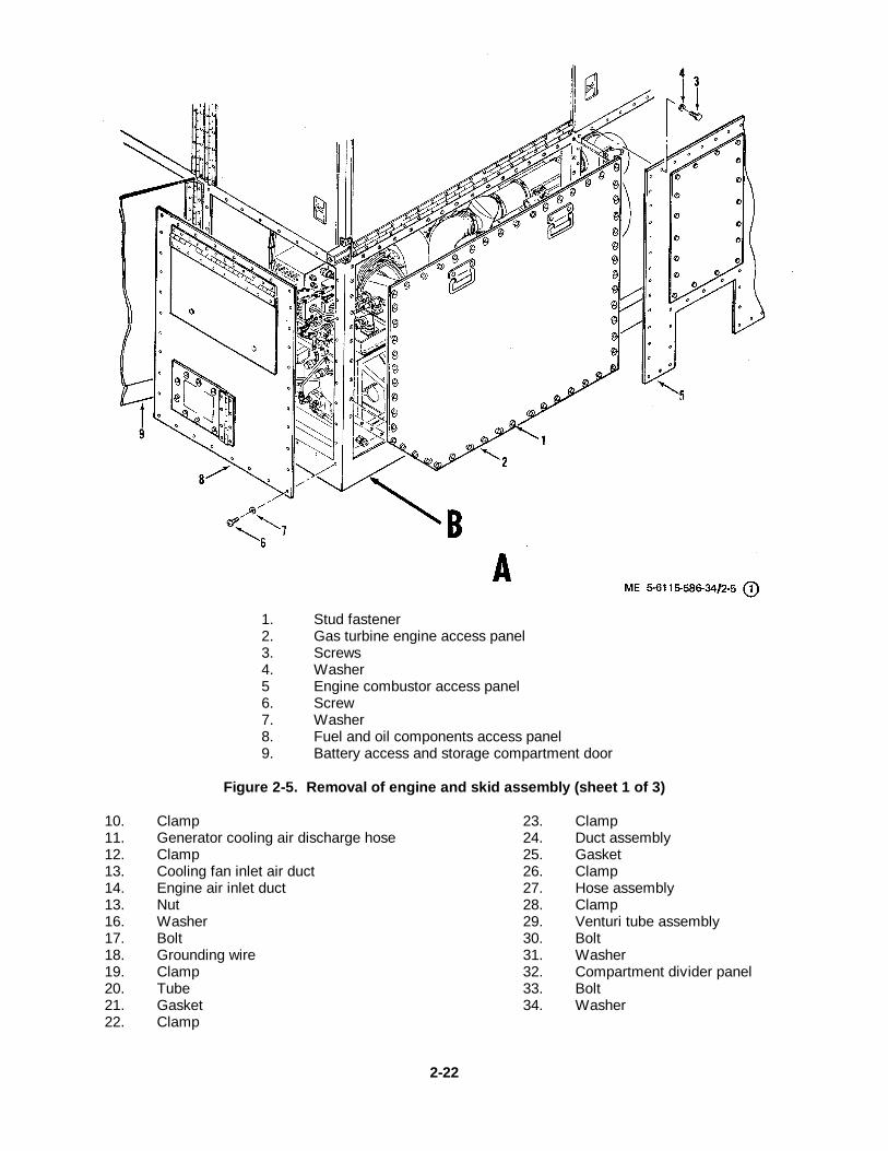
1. Stud fastener2. Gas turbine engine access panel3. Screws4. Washer5 Engine combustor access panel6. Screw7. Washer8. Fuel and oil components access panel9. Battery access and storage compartment door
Figure 2-5. Removal of engine and skid assembly (sheet 1 of 3)
10. Clamp11. Generator cooling air discharge hose12. Clamp13. Cooling fan inlet air duct14. Engine air inlet duct13. Nut16. Washer17. Bolt18. Grounding wire19. Clamp20. Tube21. Gasket22. Clamp
23. Clamp24. Duct assembly25. Gasket26. Clamp27. Hose assembly28. Clamp29. Venturi tube assembly30. Bolt31. Washer32. Compartment divider panel33. Bolt34. Washer
2-22
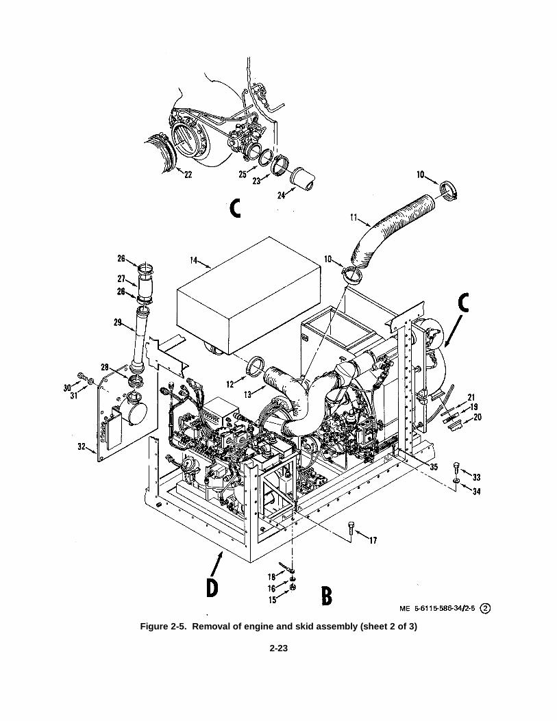
Figure 2-5. Removal of engine and skid assembly (sheet 2 of 3)
2-23
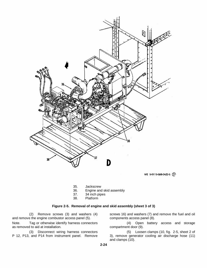
35. Jackscrew36. Engine and skid assembly37. 34 inch pipes38. Platform
Figure 2-5. Removal of engine and skid assembly (sheet 3 of 3)
(2) Remove screws (3) and washers (4)and remove the engine combustor access panel (5).Note. Tag or otherwise identify harness connectorsas removed to aid at installation.
(3) Disconnect wiring harness connectorsP 12, P13, and P14 from instrument panel. Remove
screws 16) and washers (7) and remove the fuel and oilcomponents access panel (8).
(4) Open battery access and storagecompartment door (9).
(5) Loosen clamps (10, fig. 2-5, sheet 2 of3), remove generator cooling air discharge hose (11)and clamps (10).
2-24
(6) Loosen clamp (12), separate coolingfan inlet air duct (13) from engine air inlet duct (14) andremove clamp (12).
(7) Unlatch four suitcase type clampsholding engine air inlet duct (14) to engine air inletplenum and remove engine air inlet duct (14).
(8) Disconnect five harness connectorslocated near top of divider panel between enginecompartment battery access and storage compartment,connectors (P49, P50, P51, P52 and P106). Disconnectone harness connector (P38) located on top of enginecompartment. Disconnect one harness connectorlocated near bottom of divider panel between enginecompartment and battery access and storagecompartment (connector P64).
(9) Remove nut (15), washer (16), and bolt(17) to disconnect grounding wire (18) from enclosureframe.
(10) Loosen clamp (19) at compressed airdischarge flange. Disconnect tube (20), remove gasket(21) and clamp (19).
(11) Remove clamp (22) at turbine exhaustflange.
(12) Loosen clamp (23) at bleed-air loadcontrol valve, separate duct assembly (24) from loadcontrol valve and remove gasket (25) and clamp (23).
(13) Loosen clamps (26), remove hoseassembly (27) and clamps (26). Loosen clamp (28),remove venturi tube assembly (29) and clamp (28).Remove bolts (30), washers (31) and compartmentdivider panel (32).
(14) Drain oil tank and then remove oil tankdrain hose from bottom of oil tank and from enclosureframe fitting. Remove drain tube from the spill drainbelow the oil filler cap.
(15) Remove bolts (33) and washers (34)from skid assembly mounts.
(16) Install jackscrews (35, fig. 2-5, sheet 3of 3) and turn down to raise the engine and skidassembly (36) approximately one inch above theenclosure frame. Place four 3/4 inch pipes (37), orequivalent, across the enclosure frame under the engine
and skid assembly. Turn jackscrews (35) to lower skidassembly to pipes (37).
(17) Position platform (38) in front of theenclosure and adjacent to the power plant enclosureframe. Roll skid assembly out of enclosure, positioningpipes (37) from the enclosure to the platform (38) sothat an even rolling motion is maintained.
(18) Turn jackscrews down to raise engineand skid assembly. Remove pipes (37) and turnjackscrews to lower skid assembly to platform.
b. Installation. Install engine and skid assemblywith all attached components in reverse order ofremoval procedure using figure 2-5 as a guide. Performpower plant test procedures described in paragraph 2-5after engine and skid assembly installation to ensureproper power plant performance.2-12. Removal and Installation of Engine and SkidAssembly Major Components
a. Generators. Refer to TM 5-6115-586-12 forremoval and installation instructions for the 400 Hzgenerator and the 60 Hz generator.
b. Gas Turbine Engine.(1) Removal.
(a) Refer to TM 5-6115-586-12 andremove the 400 Hz generator and the 60 Hz generator.Note. Tag or otherwise identify harness connectorsand wires as removed to aid at installation.
(b) Remove wiring harnessconnectors as required and feasible to accomplishengine removal. Remove clamps to allow removal ofharness with engine.Note. Tag or otherwise identify hose and tubeassemblies as removed to aid at installation.
(c) Loosen or remove hose and tubeassemblies as required and feasible to accomplishengine removal. Refer to paragraph 3-3 as an aid toidentifying and removing tube assemblies.
(d) Loosen four clamps (1, fig. 2-6)and support (2). Remove the tee and duct (3) andsupport (2) as an assembly. Remove ducts (4) and oiltemperature regulator (5).
2-25
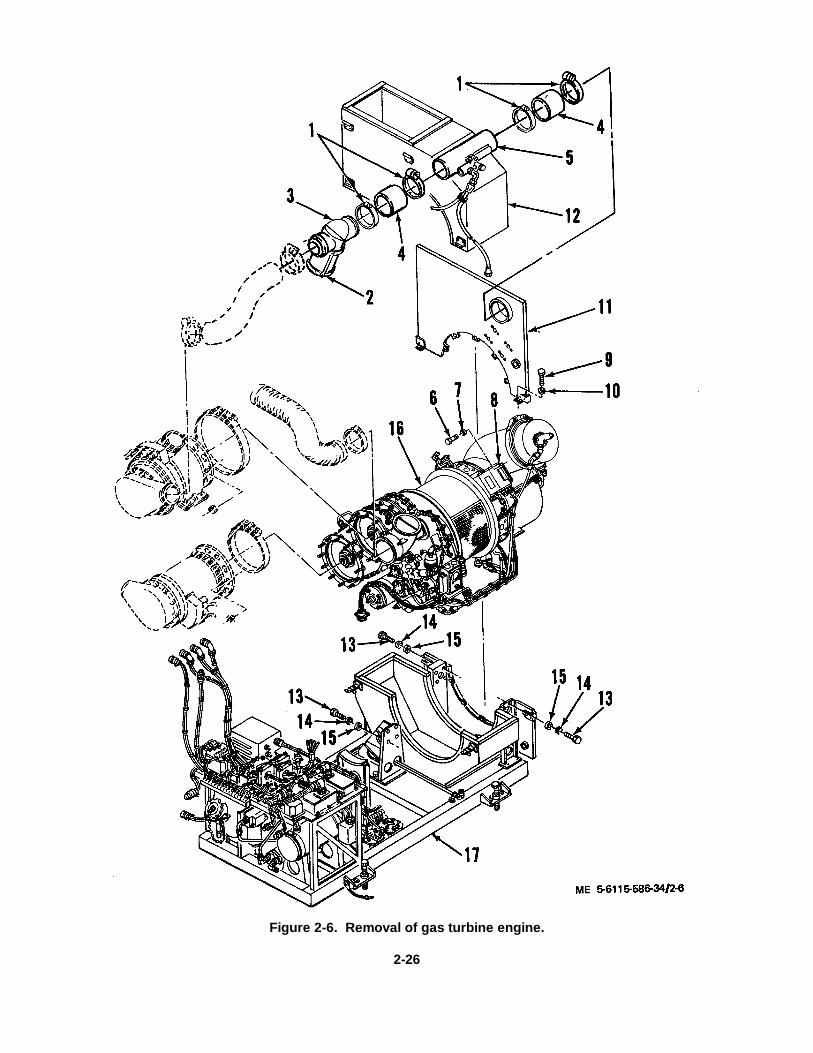
Figure 2-6. Removal of gas turbine engine.
2-26
KEY to figure 2-6. 9. Bolt1. Clamps 10. Washer2. Support 11. Upper heat shield3. Tee and duct 12. Inlet air plenum4. Duct 13. Bolt5. Oil temperature regulator 14. Washer6. Bolt 15. Spacer7. Washer 16. Gas turbine engine8. Ignition unit 17. Skid assembly
Warning. Do not remove ignition unit or ignitionlead without grounding. The high tension ignitionlead must be grounded as soon as it is removedfrom the igniter plug. Ground by touching thecontact spring in the lead to the igniter.
(e) Remove four bolts (6) andwashers (7), and remove ignition unit (8) from upperheat shield (11).Note. Keep ignition lead and ignition unit with gasturbine engine.
(f) Remove bolts (9), washers (10),and upper heat shield (11).
(g) Unlatch inlet air plenum (12) tophalf, and remove from bottom half.Note. Tag or otherwise identify harness connectorand wires as removed to aid at installation.
(h) Attach beam type adjustable slingwith overhead hoist of at least 2000 lb. capacity.Remove bolts (13), washers (14), spacers (15) and threemounts and lift engine (16) from skid assembly (17).Guide wiring harness assembly and hose and tube
assemblies to prevent damage during removal. Installengine in gas turbine engine portable stand, usingmaintenance stand adapters. Remove beam typeadjustable sling.
(2) Installation.(a) Install gas turbine engine in
reverse order of removal procedures, using figure 2-6 asa guide.
(b) Refer to TM 5-6115-586-12 andinstall the generators.
c. Upper Electric Power Chassis Assembly.Refer to TM 5-6115-586-12.
d. Lower Electric Power Chassis Assembly.Refer to TM 5-6115-586-12.2-13. Removal and Installation of Auxiliary PowerTray Assembly
a. Removal.(1) Disconnect four wire harness leads
(wire numbers X200AG4N, X200AH8N, X200AJ4N, andX200AK8N) from the ground terminal E3 (located on thereceptacle panel).
(2) Disconnect connector (P103) from rearof auxiliary power tray assembly.
(3) Remove four screws and washers thatattach the front panel to the enclosure and seven screwsand washers that attach the tray to the enclosure.Remove the auxiliary power tray assembly.
b. Installation. Install the auxiliary power trayassembly by reversing the removal procedure.
2-27
CHAPTER 3
REPAIR OF ENGINE
Section I. ENGINE ELECTRICAL AND PLUMBING INSTALLATION
3-1. GeneralThis section includes instructions for repair of the enginewire harness assembly, hose assemblies, tubeassemblies and fittings. Refer to TM 5-6115-586-12 forschematics of the electrical, fuel, bleedair andlubrication systems as an aid to troubleshooting andrepair. Refer to TM 5-6115-586-12 for a description ofthese components.3-2. Gas Turbine Engine Branched Wire HarnessAssembly
a. General. The gas turbine engine branchedwire harness assembly is a multiple lead wiring harnessfor engine electrical components and control circuits.All circuits for the engine are connected to the powerplant electrical system through connector J36. Beforethe wire harness assembly is removed, tag electrical
leads, note location of clamps and routing of harness,and location of lockwire as an aid at installation.
b. Removal. Remove gas turbine engine wireharness assembly according to sequence of indexnumbers 1 through 14 assigned to figure 3-1.
c. Disassembly. After inspection and testing,disassemble the wire harness only as required for repairor replacement using the sequence of index numbers 1through 15 assigned to figure 3-2 and figure 3-3 asguides.
d. Cleaning and Inspection.(1) Clean harness assembly with lint-free
cloth or soft bristle brush.(2) Visually inspect harness assembly
wiring for wire breaks, frayed or burned insulation,chafing or other evidence of damage.
3-1
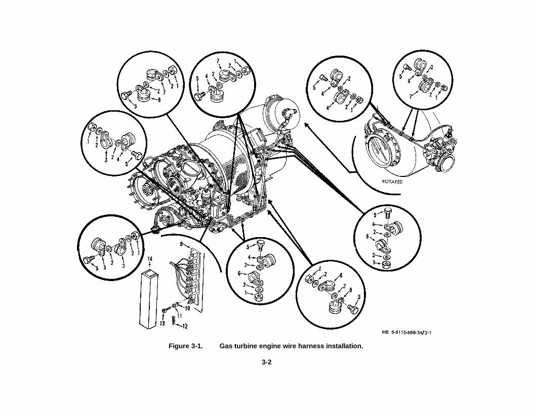
Figure 3-1. Gas turbine engine wire harness installation.
3-2
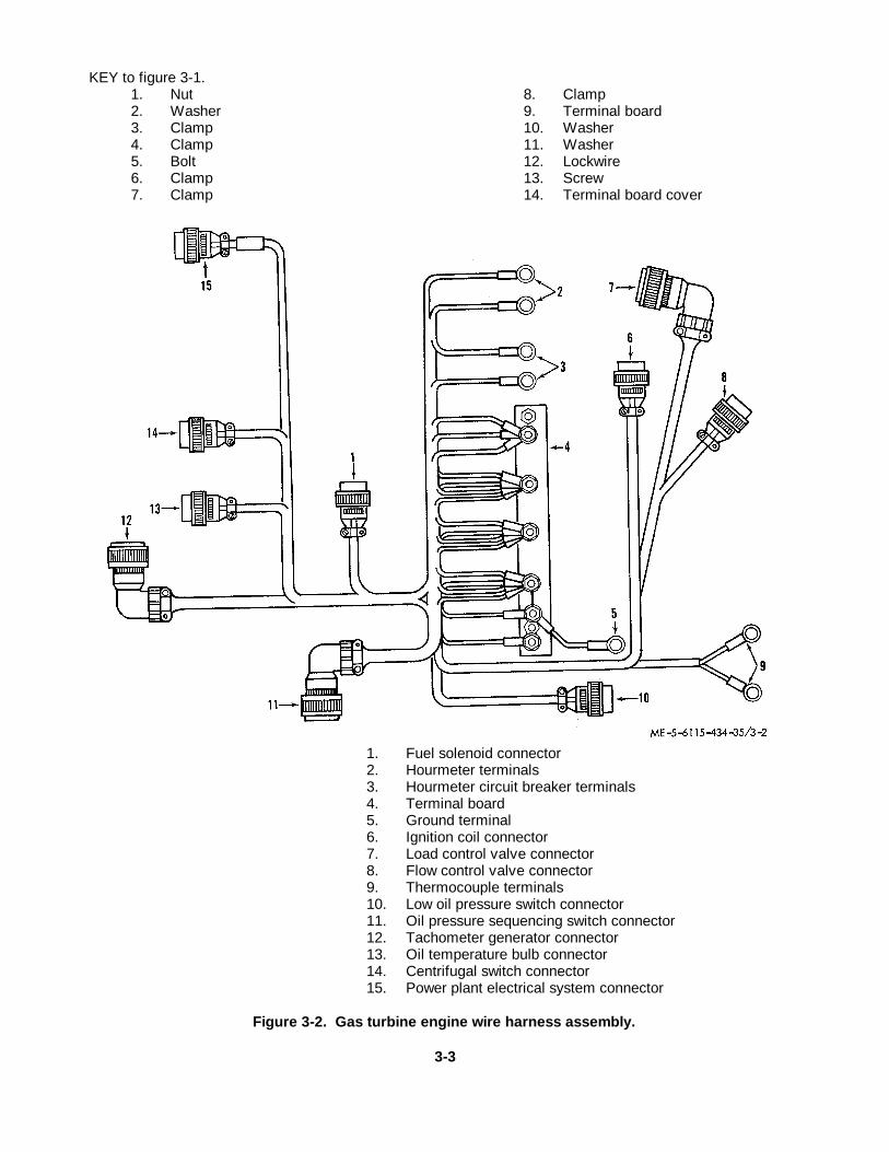
KEY to figure 3-1.1. Nut 8. Clamp2. Washer 9. Terminal board3. Clamp 10. Washer4. Clamp 11. Washer5. Bolt 12. Lockwire6. Clamp 13. Screw7. Clamp 14. Terminal board cover
1. Fuel solenoid connector2. Hourmeter terminals3. Hourmeter circuit breaker terminals4. Terminal board5. Ground terminal6. Ignition coil connector7. Load control valve connector8. Flow control valve connector9. Thermocouple terminals10. Low oil pressure switch connector11. Oil pressure sequencing switch connector12. Tachometer generator connector13. Oil temperature bulb connector14. Centrifugal switch connector15. Power plant electrical system connector
Figure 3-2. Gas turbine engine wire harness assembly.
3-3
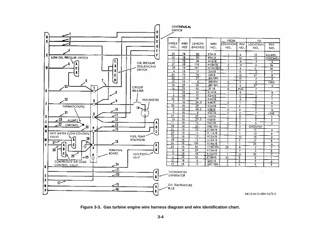
Figure 3-3. Gas turbine engine wire harness diagram and wire identification chart.
3-4
(3) Inspect connectors for crossed,stripped or peened threads and for bent, broken, orotherwise damaged pins.
e. Test. Refer to figure 3-3 and checkindividual wires for continuity using a multimeter.
f. Repair and Replacement.(1) Replace any part that does not meet
inspection requirements and is damaged beyond simplerepair. Solder all connectors except thermocoupleterminals according to Military Specification MIL-S-6872using solder in accordance with Federal SpecificationQQ-S-571, Composition Sn60.
(2) Solder thermocouple terminalaccording to Military Specification MIL-S-6872 usingsolder in accordance with Federal Specification QQ-S-561, Class 5.
(3) If wire (22, fig. 3-3), or wire (23)require replacement, use wire in accordance withMilitary Specification MIL-W-5846B, Type II, Class A.
(4) If wires (25, 26, 27, or 29, fig. 3-3)require replacement, use wire in accordance withMilitary Specification MIL-W-25038, Size 18.
(5) All other wire to be in accordance withMilitary Standard MS27110-18.
(6) Identify all leads with wire number inaccordance with figure 3-3.
(7) If connector and terminal locationmarkers are damaged or missing, apply new markers.
(8) Tie wires at all junctions and at allother places as required with cable tie strap.
g. Reassembly. Assemble harness assembly inreverse order of disassembly.
h. Installation.(1) Install harness in reverse order of
removal procedure, using figure 3-1 as a guide andobserve the following.
(2) Remove all paint from starter flangebefore attaching harness ground wire. Use starter motorattaching nut to attach harness ground wire to starterflange.
(3) Lockwire (terminal board, cover)according to Military Standard MS33540.3-3. Plumbing Installation
a. General. The engine and skid plumbinginstallation provides interconnection of fuel, lubrication,and bleed air system components. The hoseassemblies consist of metallic-braid-protected hoseswith permanently secured end fittings. Support clampshold the tube and hose assemblies in place and preventthem from directly contacting the skid where they wouldbe subject to early failure due to vibration. Tag the hoseand tube assemblies before removal, and note locationof clamps and routing of plumbing as an aid atinstallation.
b. Removal. Remove hose and tube andplumbing fittings according to sequence of indexnumbers 1 through 193 assigned to figure 3-4.
3-5
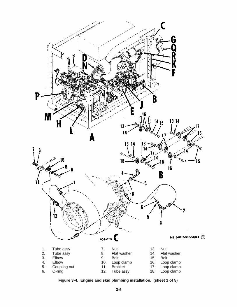
1. Tube assy 7. Nut 13. Nut2. Tube assy 8. Flat washer 14. Flat washer3. Elbow 9. Bolt 15. Bolt4. Elbow 10. Loop clamp 16. Loop clamp5. Coupling nut 11. Bracket 17. Loop clamp6. O-ring 12. Tube assy 18. Loop clamp
Figure 3-4. Engine and skid plumbing installation. (sheet 1 of 5)
3-6

3-7
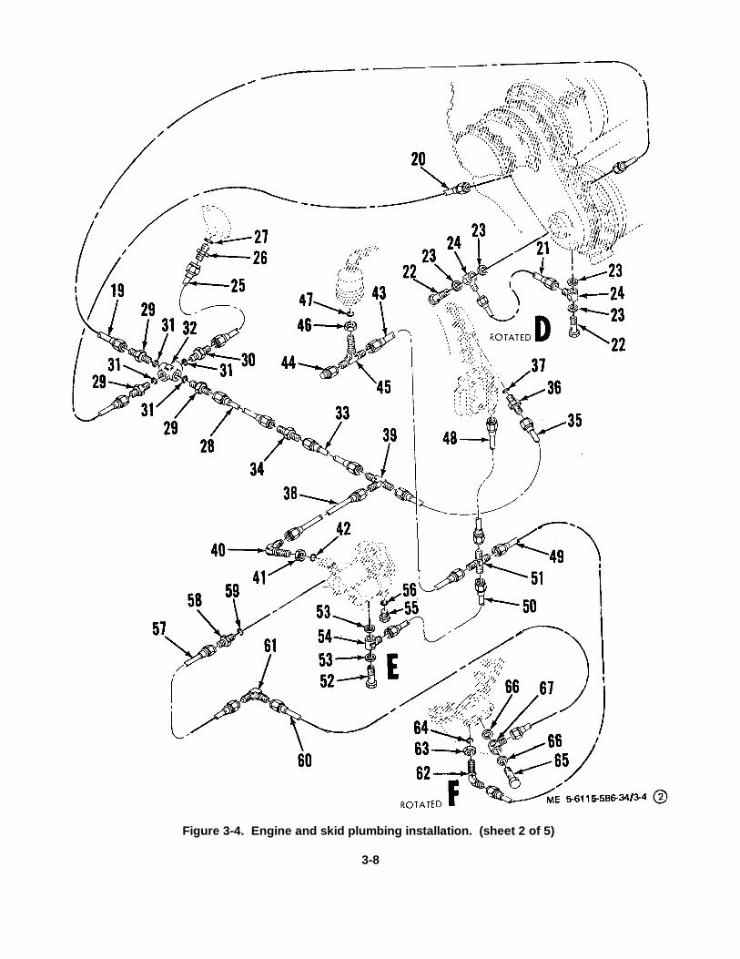
Figure 3-4. Engine and skid plumbing installation. (sheet 2 of 5)
3-8

KEY to figure 3-4-Continued: 43. Tube assy19. Tube assy 44. Tube cap20. Tube assy 45. Tee21. Tube assy 46. Coupling nut22. Fluid passage bolt 47. O-ring23. Packing 48. Tube assy24. Connector 40. Tube assy25. Tube assy 50. Tube assy26. Union 51. Tube cross27. 0-ring 52. Fluid passage bolt28. Tube assy 53. Packing29. Union 54. Connector30. Reducer 55. Oil pump plug31. 0-ring 56. Packing32. Cross fitting 57. Tube33. Tube assy 58. Reducer34. Reducer 59. Packing35. Tube assy 60. Tube assy36. Nipple 61. Elbow37. Packing 62. Elbow38. Tube assy 63. Coupling nut30). Tee 64. O-ring40. Elbow 65. Fluid passage bolt41. Nut 66. Packing42. Packing 67. Connector
3-9
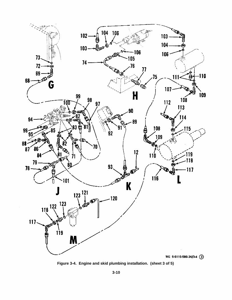
Figure 3-4. Engine and skid plumbing installation. (sheet 3 of 5)
3-10

KEY to figure 3-4-Continued:68. Tube assy 96. 0-ring69. Elbow 97. Hose assy70. Tube cap 98. Elbow71. Tee 99. Nut72. Coupling nut 100. O-ring73. 0-ring 101. Tube assy74. Tube assy 102. Tube assy75. Tube cap 103. Nut76. Nut 104. Nut77. Union 105. Reducer78. Tube assy 106. 0-ring79. Tee 107. Tube assy80. Tube assy 108. Elbow81. Elbow 109. Nut82. Coupling nut 110. Plug/bleeder83. 0-ring 111. O-ring84. Tube assy 112. Tube assy85. Tube cap 113. Elbow86. Tee 114. Nut87. Nut 115. O-ring88. 0-ring 116. Tube assy89. Tube assy 117 Elbow90. Elbow assy 118. Nut91. Coupling nut 119. O-ring92. O-ring 120. Tube assy93. Tee 121. Reducer94. Lockwire 122. Bushing95. Plug/bleeder-ring 123. O-ring
3-11
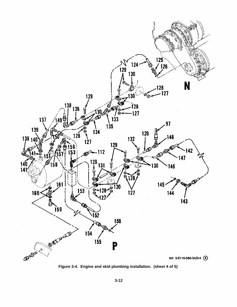
Figure 3-4. Engine and skid plumbing installation. (sheet 4 of 5)
3-12
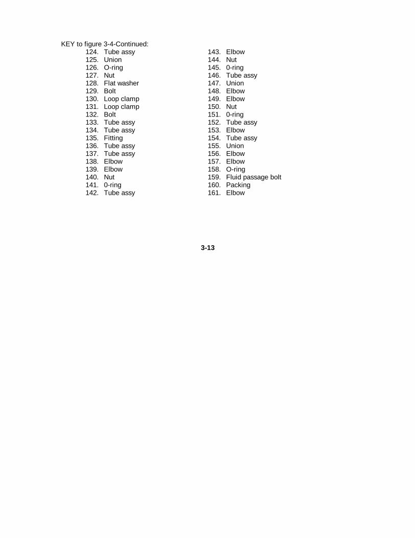
KEY to figure 3-4-Continued:124. Tube assy 143. Elbow125. Union 144. Nut126. O-ring 145. 0-ring127. Nut 146. Tube assy128. Flat washer 147. Union129. Bolt 148. Elbow130. Loop clamp 149. Elbow131. Loop clamp 150. Nut132. Bolt 151. 0-ring133. Tube assy 152. Tube assy134. Tube assy 153. Elbow135. Fitting 154. Tube assy136. Tube assy 155. Union137. Tube assy 156. Elbow138. Elbow 157. Elbow139. Elbow 158. O-ring140. Nut 159. Fluid passage bolt141. 0-ring 160. Packing142. Tube assy 161. Elbow
3-13
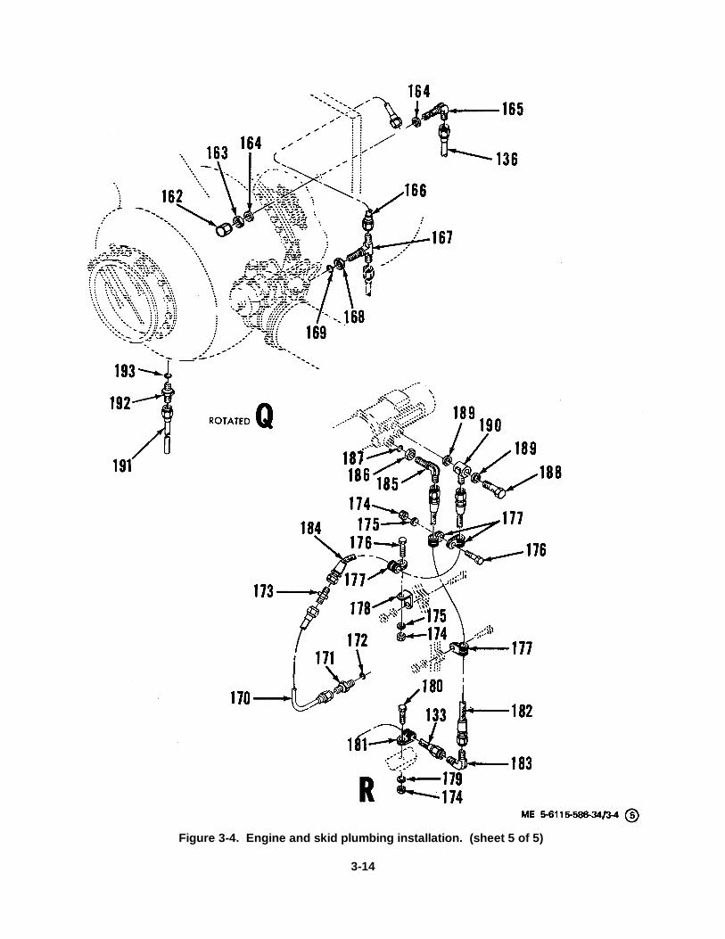
Figure 3-4. Engine and skid plumbing installation. (sheet 5 of 5)
3-14
KEY to figure 3-4-Continued:162. Cap 178. Bracket163. Nut 179. Flat washer164. Flat washer 180. Bolt165. Elbow 181. Loop clamp166. Tube assy 182. Hose assy167. Tee 183. Elbow168. Nut 184. Hose assy169. O-ring 185. Elbow170. Tube assy 186. Nut171. Union 187. O-ring172. O-ring 188. Fluid passage bolt173. Union 189. Packing174. Nut 190. Elbow175. Flat washer 191. Tube assy176. Bolt 192. Relief valve177. Loop clamp 193. O-ring
c. Cleaning, Inspection and Repair.(1) Clean hose and tube and plumbing
fittings with an approved cleaning solvent and drythoroughly with filtered compressed air.
(2) Inspect all threaded parts for stripped,crossed, or peened threads. If threads are damagedbeyond simple repair, replace part.
(3) Inspect hose for cracks, breaks,chafing and damage to hose interior. If damaged,replace hose assembly.
(4) Inspect tube for kinks, bends, cracks,or other damage which might restrict flow or result in
leakage. Inspect connection nuts and sleeves on tubefor loose sleeves or damage to nuts. If damaged,replace tube.
(5) Inspect plumbing fittings for cracks orclogged passages. Clean clogged passages andreplace cracked fittings.
(6) Replace all gaskets and packings ateach overhaul regardless of condition.
d. Installation. Install hose and tube andplumbing fittings in reverse order of removal proceduresof paragraph b. above.
Section II. ENGINE ACCESSORIES
3-4. GeneralThis section provides instructions for repair andreplacement allocated to direct support and generalsupport maintenance for engine accessory components.The components included in this section are the starterassembly, fuel control assembly, fuel atomizerassembly, and oil temperature regulator valve. Refer toTM 5-6115-586-12 for repair instructions on otheraccessory components.3-5. Starter Assembly
a. General. The starter is a 24 VDC hightorque motor with a pawl and clutch mechanisminstalled to absorb initial shock of starter rotation.Repair instructions for the starter clutch assembly andfor replacement of brushes are provided in thisparagraph. If repair of the motor is necessary, refer todepot maintenance.
b. Removal. Refer to TM 5-6115-586-12 andremove the starter assembly according to theinstructions provided.
c. Disassembly of Clutch Assembly. Refer tofigure 3-5 and disassemble the starter clutch assemblyas follows:
(1) Do not remove screws (2) ornameplate (3) from the starter assembly (1) unlessreplacement of the ,nameplate is required afterinspection.
(2) Note and record the position of thepawls (6) and spider (7) as an aid at reassembly.Support starter assembly (1) on the workbench andstraighten the end of the spring (8) so that ring (4) andassembled pawls and spider may be removed. Removepins (5) to disassemble pawls (6) from spider (7).
3-15

1. Starter assembly 12. Plate2. Screw 13. Ring3. Nameplate 14. Plate4. Ring 15. Ring5. Pin 16. Plate6. Pawl 17. Retainer7. Spider 18. Plate8. Spring 19. Spring9. Ring 20. Pin10. Washer 21. Housing11. Ring 22. Motor, engine starter
Figure 3-5. Starter clutch assembly.
(3) Remove spring (8). Remove ring (9),washer (10), and ring(11).
(4) Remove plate (12), ring (13), plate(14), ring (15), plate (16), retainer (17), plate (18), andspring (19).
(5) Remove pin (20) and then removehousing (21) from motor (22).
d. Cleaning and Inspection of Clutch Assembly.(1) Clean all disassembled starter clutch
assembly components with a dry cleaning solvent (FedSpec P-D-680) and dry with filtered compressed air.Note. Dimensional checks are not necessary insteps (2) through (5) unless parts show visible evidenceof wear or other damage.
(2) Check pins (5, fig. 3-5) for damage towearing surface. Outside diameter of wear surface shallbe 0.1223 inch (minimum).
(3) Inspect pawls (6) for nicks, flats, orother damage on wearing surface of engaging end.Replace pawls (6) if flats, nicks, or other damage isobserved.
(4) Inspect pin holes in spider (7) for wear.Hole diameter shall be 0.1245 inch to 0.1255 inch.
(5) Inspect rings (11, 13, 15), retainer (17)and housing (21) for wear, nicks, burrs, grooves, galling,corrosion, or other damage. Ring (11) shall have a flatfinish of AA64 or better, rings (13, 15) shall have a finishof AA32, or better. Sides of rings (13, 15) shall beparallel within 0.002 inch TIR (total indicator reading).Retainer (17) shall have a flange thickness of 0.075 inch(minimum), faces of flange shall be parallel within 0.002inch TIR, and flange surface shall have 'a finish ofAA32, or better. Wear in grooves of housing (21) shallnot exceed 0.010 inch (maximum).
(6) Inspect plates (12, 14, 16, 18) forgalling or other damage. Replace plates (12, 14, 16, 18)if breaks in bonding material are observed.
(7) Inspect all threaded parts for stripped,crossed, or peened threads, or foreign particlesimbedded in threads.
(8) Perform magnetic particle inspectionon pin (5), pawl (6), spider (7), rings (11, 13, 15),retainer (17) and housing (21) in accordance withMilitary Specification MIL-I-6868.
3-16
(9) Inspect nameplate (2) for legibility.e. Repair and Replacement of Clutch
Assembly.(1) Remove any minor nicks, scratches,
burrs or mild corrosion from clutch components with fineabrasive paper (Fed Spec P-P-101, No. 600 grit). Partsshall meet applicable inspection dimensions after repair.After repair, clean parts thoroughly.
(2) Replace spring (8, fig. 3-5).(3) If nameplate (2) is defective, apply zinc
chromate primer (Mil Spec MIL P-8585) to screws (1)and install new nameplate before primer dries.
(4) Replace all other damaged orexcessively worn parts. If threads are damaged beyondsimple repair, replace part.
f. Reassembly of Clutch Assembly.(1) Apply light film of oil (Military
Specification MIL-L-7808) to both sides of plates (14,16, fig. 3-5), rings (13, 15) and flared end of retainer(17).
(2) Insert spring (19) in bottom of housing(21) with convex side toward starter motor. Install plate
(18) on top of spring (19) with smooth (unbounded) sidenext to concave side of spring.
(3) Install plate ( 16) on retainer (17).Install ring (15) on plate (16) align internal spline teeth ofring (15) with external spline teeth of retainer.
(4) Install plate (14) on retainer (17).Install ring (131 after aligning teeth.
(5) Install plate (12) over retainer (17) withrough (bonded) side next to ring (13).Note. Do not install ring (9) at this time.
(6) Install ring (11 over retainer (17) withsmooth (unslotted) side next to plate (12). Installwasher (10) over retainer.
(7) Insert pawls (6i) in spider (7), alignholes and insert pins (5).
(8) Install assembled parts (5, 6, 7) insideretainer (7) with pawls (6) protruding through slots inretainer and with spring hole in spider clockwise 90degrees to spring hole in wall retainer, as viewed fromflange end of retainer. See figure 3-6, items 1-6, forproper installation of pawls in the spider.Note. Make sure that spring holds pawls in theretracted position. If not, reverse pawls in spider.
3-17
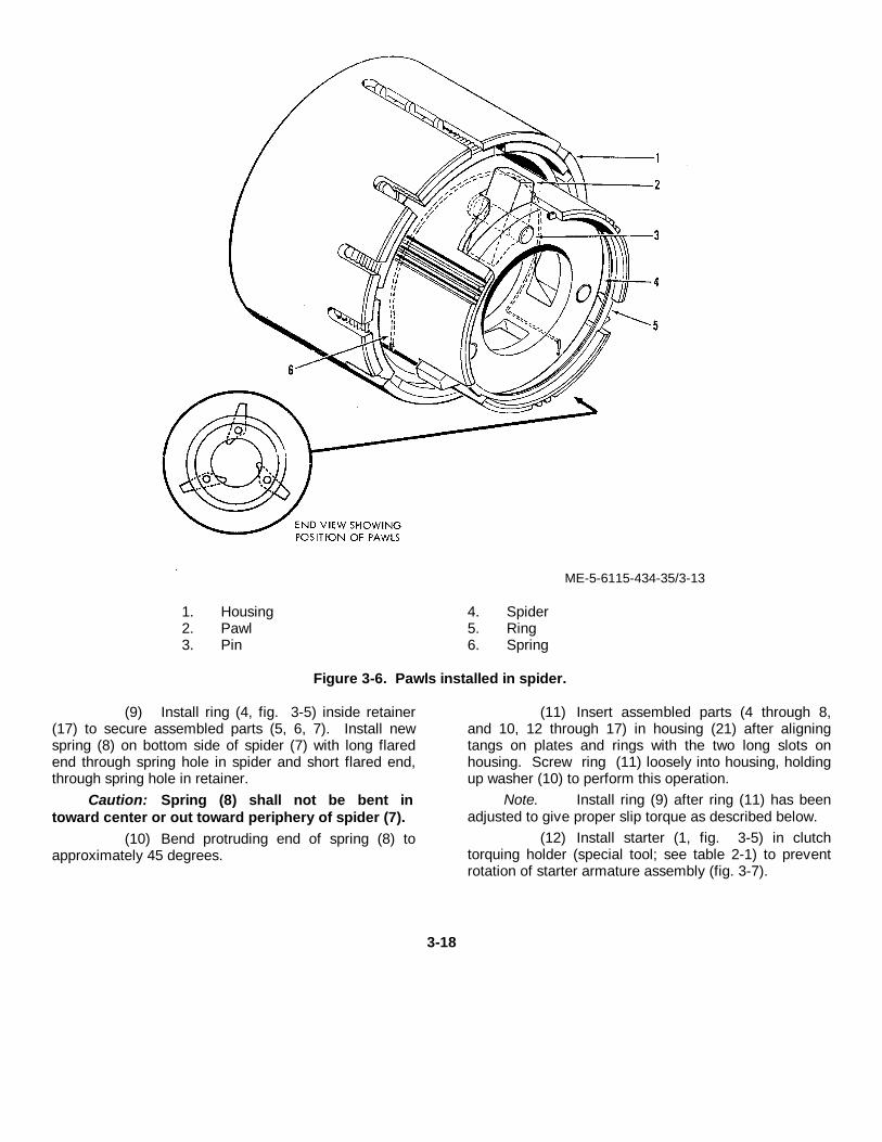
ME-5-6115-434-35/3-13
1. Housing 4. Spider2. Pawl 5. Ring3. Pin 6. Spring
Figure 3-6. Pawls installed in spider.
(9) Install ring (4, fig. 3-5) inside retainer(17) to secure assembled parts (5, 6, 7). Install newspring (8) on bottom side of spider (7) with long flaredend through spring hole in spider and short flared end,through spring hole in retainer.
Caution: Spring (8) shall not be bent intoward center or out toward periphery of spider (7).
(10) Bend protruding end of spring (8) toapproximately 45 degrees.
(11) Insert assembled parts (4 through 8,and 10, 12 through 17) in housing (21) after aligningtangs on plates and rings with the two long slots onhousing. Screw ring (11) loosely into housing, holdingup washer (10) to perform this operation.
Note. Install ring (9) after ring (11) has beenadjusted to give proper slip torque as described below.
(12) Install starter (1, fig. 3-5) in clutchtorquing holder (special tool; see table 2-1) to preventrotation of starter armature assembly (fig. 3-7).
3-18
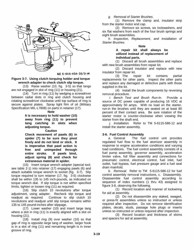
Figure 3-7. Using clutch torquing holder and torquewrench adapter to check clutch slip torque.
(13) Raise washer (10, fig. 3-5) so that tangsare not engaged in slot of ring (11) or housing (21).
(14) Turn in ring (11) by wedging a screwdriverbetween radial slots in ring and clutch housing androtating screwdriver clockwise until top surface of ring issecure against plates. Spray light film of oil (MilitarySpecification MIL-L7808) on parts in retainer (17).
NoteIt is necessary to hold washer (10)away from ring (11) to preventtang catching in slots whenadjusting torque.
CautionCheck movement of pawls (6) inspider (7) to be sure they pivotfreely and do not bind or stick. Itis imperative that pawl action isfree and unimpeded throughentire stroke. If pawls bind,adjust spring (8) and check forextraneous material in spider.
(15) Insert torque wrench adapter (special tool;see table 2-1) into retainer (17) engaging pawls (6) andattach suitable torque wrench to socket (fig. 3-7). Sliptorque required to turn retainer (17, fig. 3-5) clockwiseshall be within 135 to 145 inch-pounds, as indicated ontorque wrench dial. If slip torque is not within specifiedlimits, tighten or loosen ring (11) as required.
(16) Slip clutch 10 revolutions after torqueadjustment, using adapter. Recheck slip torque andreadjust as required. Continue to slip clutch 10revolutions and readjust until slip torque remains within135 to 145 pound-inches after slippage.
(17) Lower washer (10) and insert large tangwhere a slot in ring (11) is exactly aligned with a slot onhousing (21).
(18) Install ring (9) over washer (10) so thatgap of ring is opposite large tang of washer, larger hookis in a slot of ring (11) and remaining length is in innergroove of ring.
g. Removal of Starter Brushes.(1) Remove the clamp and, insulator strip
from the starter motor end cap.(2) Remove six screws, six lockwashers, and
six flat washers from each of the four brush springs andeight brush assemblies.
h. Inspection, Replacement, and Installation ofStarter Brushes.
NoteA repair kit shall always beutilized instead of replacement ofindividual parts.(1) Discard all brush assemblies and replace
with new brush assemblies from repair kit.(2) Discard insulator and replace with new
insulator from repair kit.(3) The repair kit contains partial
replacements for other parts. Inspect the other partsand replace any damaged or defective parts with thosesupplied in the kit.
(4) Install the brush components by reversingremoval procedure.
i. Bench Test and Brush Run-In. Provide asource of DC power capable of producing 16 VDC atapproximately 50 amps. With no load on the starter,run-in the brushes until they are seated on at least 80percent of their contact area. Be sure rotation of thestarter motor is counter-clockwise when viewing thestarter from the shaft end.
j. Installation. Refer to TM 5-6115-586-12 andinstall the starter assembly.
3-6. Fuel Control Assemblya. General. The fuel control unit provides
regulated fuel flow to the fuel atomizer assembly inresponse to engine acceleration conditions and varyingload conditions. The fuel control assembly consists of afuel pump assembly, governor assembly, accelerationlimiter valve, full filter assembly and connections forpneumatic control, electrical control, fuel inlet, fueloutlet, fuel bypass, fuel pressure gauge and a fuel sealdrain mainfold.
b. Removal. Refer to TM 5-6115-586-12 for fuelcontrol assembly removal instructions, c. Disassembly.Disassemble fuel control assembly according tosequence of index numbers (1 thru 43) assigned tofigure 3-8, observing the following.
(1) Record location and manner of lockwiringfor aid at assembly.
(2) Do not disassemble any staked, swaged,or press-fit assemblies unless so instructed or unlessrequired after inspection. Do not remove identificationplates, decals, studs, passage hole plugs or insertsunless so instructed or unless required after inspection.
(3) Record location and thickness of shimsand spacers for aid at assembly.
3-19
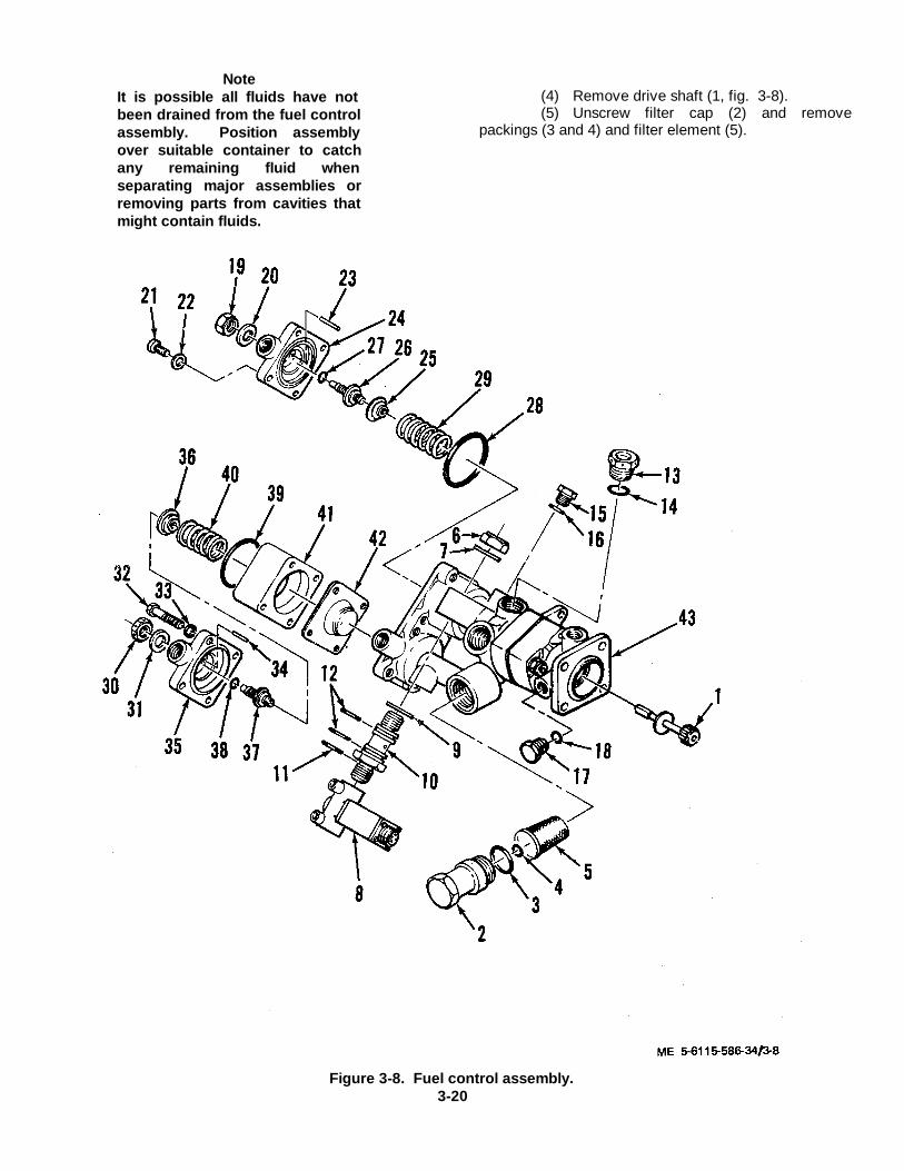
NoteIt is possible all fluids have notbeen drained from the fuel controlassembly. Position assemblyover suitable container to catchany remaining fluid whenseparating major assemblies orremoving parts from cavities thatmight contain fluids.
(4) Remove drive shaft (1, fig. 3-8).(5) Unscrew filter cap (2) and remove
packings (3 and 4) and filter element (5).
Figure 3-8. Fuel control assembly.3-20
KEY to figure 3-8.1. Drive shaft2. Filter cap3. Packing4. Packing5. Filter element6. Nut7. Washer8. Fuel solenoid valve9. Washer10. Fitting11. Gasket12. Packing13. Plug14. Gasket15. Plug16. Packing17. Plug18. Packing19. Nut20. Washer21. Screw
22. Washer23. Pin24. Cover25. Nut26. Adjustment screw27. Packing28. Packing29. Spring30. Nut31. Washer32. Screw33. Washer34. Pin35. Cover36. Nut37. Adjustment screw38. Packing39. Packing40. Spring41. Spacer42. Diaphragm assy43. Housing assy
(6) Remove nut (6), washer (7) and removefuel solenoid valve (8) with items (9 through 12)attached. Remove washers (9). Remove fitting (10)from fuel solenoid valve (8) then remove gasket (11)and packings (12) from fitting (10).
(7) Remove plug (13) with gasket (14)attached, then remove gasket (14) from plug (13).
(8) Remove plug (15) with packing (16)attached, then remove packing (16) from plug (15).
(9) Remove plug (17) with packing (18)attached, then remove packing (18) from plug (17).
(10) Remove nut (19) and washer (20) fromscrew (26) in cover (24) to release compression load ofspring (29).
NoteNut (25) has left-hand thread.
(11) Remove screws (21) and washers (22)and remove cover (24). Do not remove pin (23) fromcover unless damage is indicated by inspection.Remove nut (25), screw (26), packings (27), (28), andspring (29).
NoteIf flyweight assembly is removed,do not disassemble from thesleeve and bearing.
(12) Remove nut (30) and washer (31) fromscrew (37) in cover (35) to release compression load ofspring (40).
NoteNut (36) has left-hand thread.
(13) Remove screws (32) and washers (33)and remove cover (35). Do not remove pin (34) fromcover unless damage is indicated by inspection.Remove nut (36), screw (37), packings (38, 39), spring(40) and spacer (41).
(14) Remove diaphragm assembly (42) fromhousing assembly (43).
NoteDo not disassemble the fuelcontrol assembly further. Referadditional repair to depotmaintenance.
d. Cleaning, Inspection and Repair.(1) Cleaning. Clean all components of
control unit in an approved solvent, except solenoidvalve. Wipe valve with a lint-free cloth dampened in anapproved solvent such as trichlorethylene.
(2) Inspection.(a) Visually inspect all parts for obvious
damage, excessive wear, or abnormalities. Inspectthreaded parts for stripped, crossed, or peened threads.
(b) Inspect springs for distortion,cracks, or other damage.
(c) Check operation of solenoid valve.Apply Test Fluid (Military Specification MIL-T-5624,Grade UP-4 or JP-5) to valve inlet at 100±3psigpressure. Energize solenoid with 7.2 volts dc(maximum) at coil temperature of 80°F (27° C). Valveshall open. Slowly reduce voltage. Valve shall close at4 volts dc or less.
(d) Increase test fluid pressure to 300±3psig. Maintain coil temperature at 80° F (27° C) andenergize valve with 9.0 volts de (maximum). Valveshall open. Slowly reduce voltage. Valve shall close at4 volts dc or less.
(e) Check leakage of solenoid valve.Maintain test fluid at 300±3psig pressure and checkvalve for maximum leakage of 0.5 cc per hour. Reducetest fluid pressure to zero and remove valve from testsetup.
(f) Check for insulation breakdown ofcoil of solenoid valve (8). Apply 750 volts rms betweencase and coil for one minute. No shorting is permitted.
(g) Visually inspect shaft (1) for wear,crack, nicks, or burrs. Check square end of shaft for0.180 inch minimum across flats and 0.237 inch
3-21
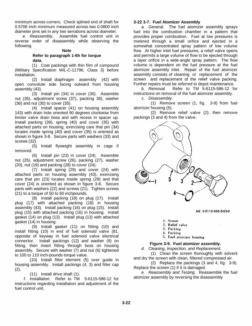
minimum across corners. Check splined end of shaft for0.5706 inch minimum measured across two 0.0800 inchdiameter pins set in any two serrations across diameter.
e. Reassembly. Assemble fuel control unit inreverse order of disassembly while observing thefollowing.
NoteRefer to paragraph 1-6h for torquedata.(1) Coat packings with thin film of compound
(Military Specification MIL-C-11796, Class 3) beforeinstallation.
(2) Install diaphragm assembly (42) withopen convolute side facing outward from housingassembly (43).
(3) Install pin (34) in cover (35). Assemblenut (36), adjustment screw (37), packing 38), washer(36) and nut (30) to cover (35).
(4) Install spacer (41) on housing assembly143) with drain hole oriented 90 degrees clockwise fromlimiter valve drain boss and with recess in spacer up.Install packing (39), spring (40) and cover (35) withattached parts on housing, exercising care that pin (34)locates inside spring (40) and cover (35) is oriented asshown in figure 3-8. Secure parts with washers (33) andscrews (32).
(5) Install flyweight assembly in cage ifremoved.
(6) Install pin (23) in cover (24). Assemblenut (25), adjustment screw (26), packing (27), washer(20), nut (19) and packing (28) to cover (24).
(7) Install spring (29) and cover (24) withattached parts on housing assembly (43), exercisingcare that pin (23) locates inside spring (29) and thatcover (24) is oriented as shown in figure 3-8. Secureparts with washers (22) and screws (21). Tighten screws(21) to a torque of 50 to 60 inchpounds.
(8) Install packing (18) on plug (17). Installplug (17) with attached packing (18) in housingassembly (43). Install packing (16) on plug (15). Installplug (15) with attached packing (16) in housing. Installgasket (14) on plug (13). Install plug (13) with attachedgasket (14) in housing.
(9) Install gasket (11) on fitting (10) andinstall fitting (10) in end of fuel solenoid valve (81,opposite of keyway in fuel solenoid valve electricalconnector. Install packings (12) and washer (9) onfitting, then insert fitting through boss on housingassembly. Secure with washer (7) and nut (6) tightenedto 100 to 110 inch-pounds torque value.
(10) Install filter element (5) over guide inhousing assembly. Install packings (4, 3) and filter cap(2).
(11) Install drive shaft (1).f. Installation. Refer to TM 5-6115-586-12 for
instructions regarding installation and adjustment of thefuel control unit.
3-22 3-7. Fuel Atomizer Assemblya. General. The fuel atomizer assembly sprays
fuel into the combustion chamber in a pattern thatprovides proper combustion. Fuel at low pressures ismetered through a small orifice and ejected in asomewhat concentrated spray pattern of low volumeflow. At higher inlet fuel pressures, a relief valve opensand permits a large volume of flow to be ejected througha layer orifice in a wide-angle spray pattern. The flowvolume is dependent on the fuel pressure at the fuelatomizer assembly inlet. Repair of the fuel atomizerassembly consists of cleaning or replacement of thescreen and replacement of the relief valve packing.Further repairs must be referred to depot maintenance.
b. Removal. Refer to TM 5-6115-586-12 forinstructions on removal of the fuel atomizer assembly.
c. Disassembly.(1) Remove screen (1, fig. 3-9) from fuel
atomizer housing (5).(2) Remove relief valve (2); then remove
packings (3 and 4) from the valve.
Figure 3-9. Fuel atomizer assembly.d. Cleaning, Inspection, and Replacement.
(1) Clean the screen thoroughly with solventand dry the screen with clean, filtered compressed air.
(2) Replace the packings (3 and 4, fig. 3-9).Replace the screen (1) if it is damaged.
e. Reassembly and Testing. Reassemble the fuelatomizer assembly by reversing the disassembly
3-22
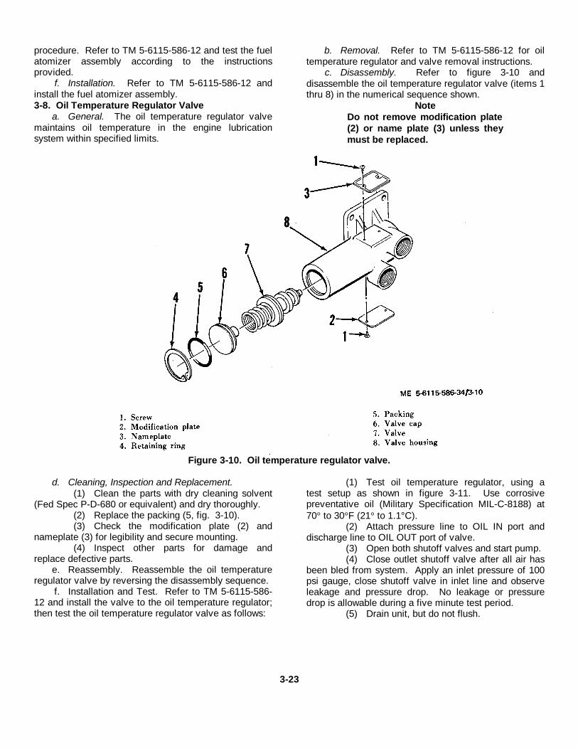
procedure. Refer to TM 5-6115-586-12 and test the fuelatomizer assembly according to the instructionsprovided.
f. Installation. Refer to TM 5-6115-586-12 andinstall the fuel atomizer assembly.3-8. Oil Temperature Regulator Valve
a. General. The oil temperature regulator valvemaintains oil temperature in the engine lubricationsystem within specified limits.
b. Removal. Refer to TM 5-6115-586-12 for oiltemperature regulator and valve removal instructions.
c. Disassembly. Refer to figure 3-10 anddisassemble the oil temperature regulator valve (items 1thru 8) in the numerical sequence shown.
NoteDo not remove modification plate(2) or name plate (3) unless theymust be replaced.
Figure 3-10. Oil temperature regulator valve.
d. Cleaning, Inspection and Replacement.(1) Clean the parts with dry cleaning solvent
(Fed Spec P-D-680 or equivalent) and dry thoroughly.(2) Replace the packing (5, fig. 3-10).(3) Check the modification plate (2) and
nameplate (3) for legibility and secure mounting.(4) Inspect other parts for damage and
replace defective parts.e. Reassembly. Reassemble the oil temperature
regulator valve by reversing the disassembly sequence.f. Installation and Test. Refer to TM 5-6115-586-
12 and install the valve to the oil temperature regulator;then test the oil temperature regulator valve as follows:
(1) Test oil temperature regulator, using atest setup as shown in figure 3-11. Use corrosivepreventative oil (Military Specification MIL-C-8188) at70° to 30°F (21° to 1.1°C).
(2) Attach pressure line to OIL IN port anddischarge line to OIL OUT port of valve.
(3) Open both shutoff valves and start pump.(4) Close outlet shutoff valve after all air has
been bled from system. Apply an inlet pressure of 100psi gauge, close shutoff valve in inlet line and observeleakage and pressure drop. No leakage or pressuredrop is allowable during a five minute test period.
(5) Drain unit, but do not flush.
3-23

Figure 3-11. Test set-up for oil temperature regulator.
Section III. DUAL PAD ACCESSORY DRIVE ASSEMBLY3-9. GeneralThis section contains repair instructions for the dual padaccessory drive assembly which is mounted to anddriven by the accessory gearcase assembly. The 60 Hzand 400 Hz generators are in turn mounted to anddriven by the dual pad accessory drive assembly.3-10. Removal
a. Removal of Generators. Refer to TM 5-6115586-12 and remove the 400 Hz generator and the60 Hz generator according to the removal instructionsprovided.
b. Removal of Dual Pad Accessory DriveAssembly.
(1) Support the dual pad accessory driveassembly; remove twelve nuts (1, fig. 3-12, sheet 1 of2) and washers (2) that secure the dual pad accessorydrive assembly (3) to the accessory gearcase assembly(9) studs, and separate the dual pad accessory driveassembly.
(2) Remove the shaft (5) and gasket (4) fromthe accessory gearcase assembly (9).3-11. Disassembly
a. Repair of the dual pad accessory driveassembly by direct support or general support
maintenance personnel shall be confined toreplacement of seals, oil jets, oil scavenge pump, andtheir associated parts and external mounting studs. Ifthe housing is cracked or otherwise defective or thedrive gears are defective, the dual pad accessory driveassembly shall be replaced by a serviceable assemblyand the defective assembly shall be returned to depotmaintenance for overhaul.
KEY to figure 3-12.1. Nut 15. Washer2. Washer 16. Inlet air plenum3. Dual pad accessory drive assy 17. Bolt4. Gasket 18. Washer5. Shaft 19. Atomizer6. Nut 20. Packing7. Bolt 21. Bolt8. Washer 22. Washer9. Accessory gearcase assembly 23. Igniter10. Packing 24. Gasket11. Shaft 25. Clamp12. Spring 26. Combustor cap13. Clamp 27. Packing14. Screw 28. Liner
3-24
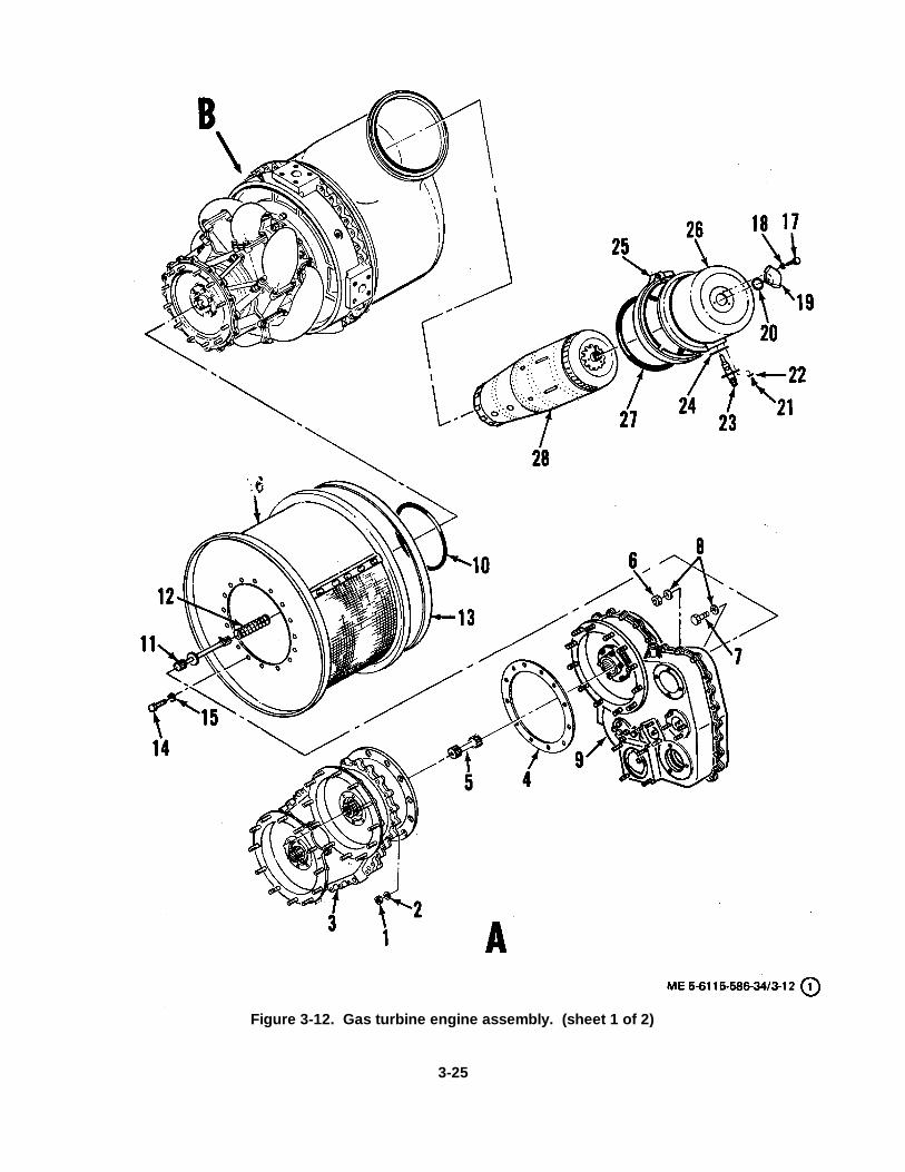
Figure 3-12. Gas turbine engine assembly. (sheet 1 of 2)
3-25
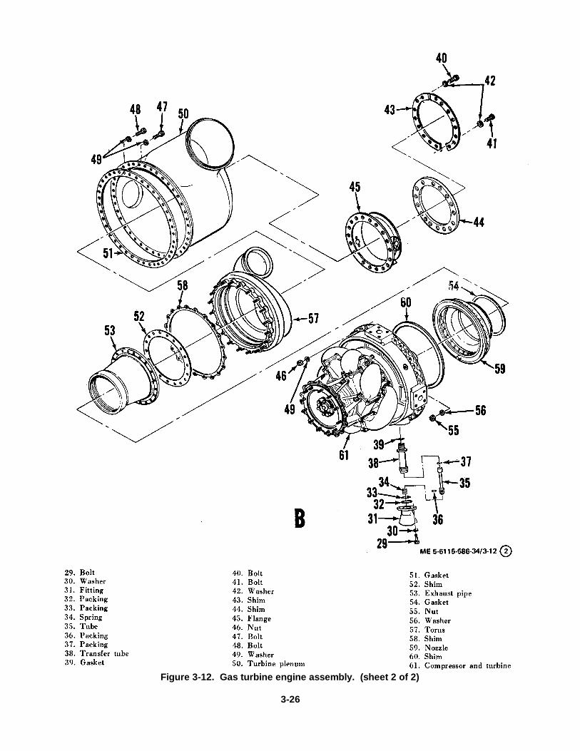
Figure 3-12. Gas turbine engine assembly. (sheet 2 of 2)
3-26
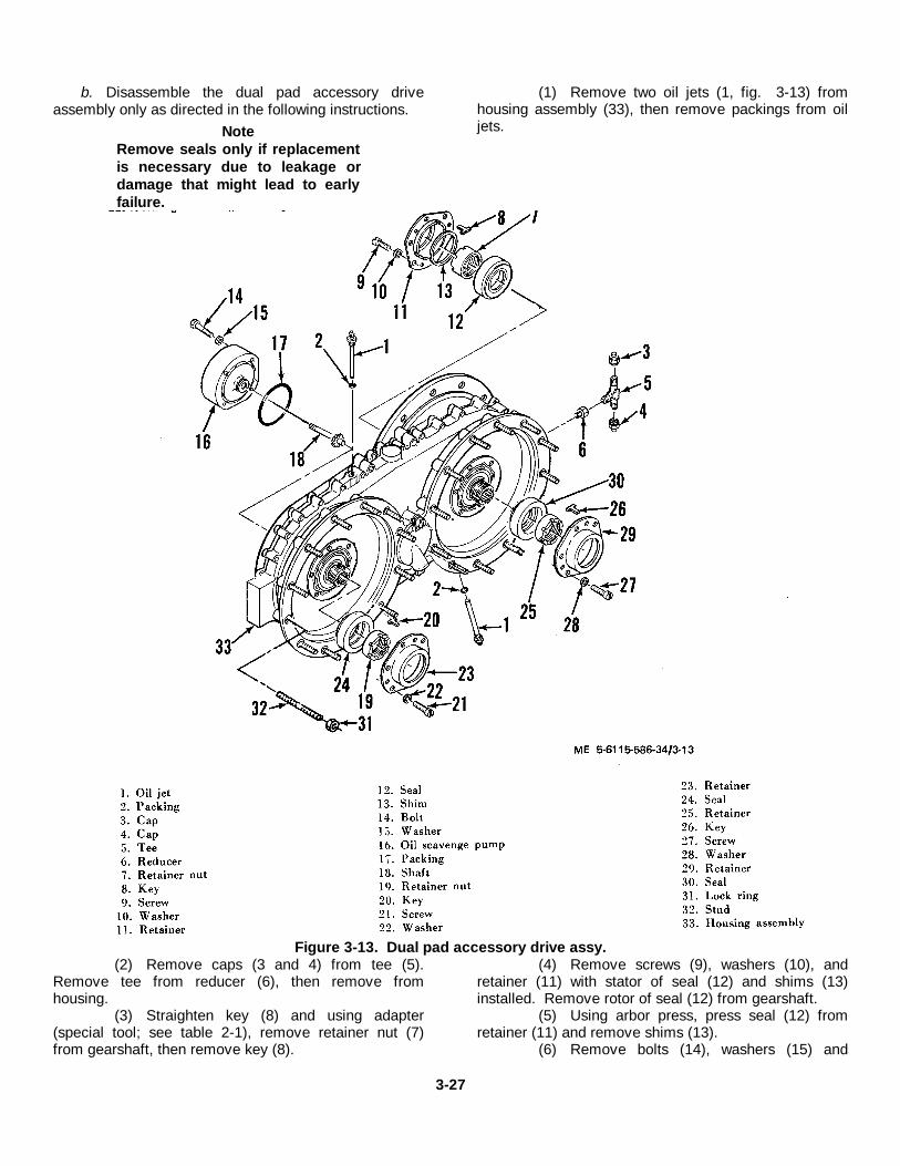
b. Disassemble the dual pad accessory driveassembly only as directed in the following instructions.
NoteRemove seals only if replacementis necessary due to leakage ordamage that might lead to earlyfailure.
(1) Remove two oil jets (1, fig. 3-13) fromhousing assembly (33), then remove packings from oiljets.
Figure 3-13. Dual pad accessory drive assy.(2) Remove caps (3 and 4) from tee (5).
Remove tee from reducer (6), then remove fromhousing.
(3) Straighten key (8) and using adapter(special tool; see table 2-1), remove retainer nut (7)from gearshaft, then remove key (8).
(4) Remove screws (9), washers (10), andretainer (11) with stator of seal (12) and shims (13)installed. Remove rotor of seal (12) from gearshaft.
(5) Using arbor press, press seal (12) fromretainer (11) and remove shims (13).
(6) Remove bolts (14), washers (15) and
3-27
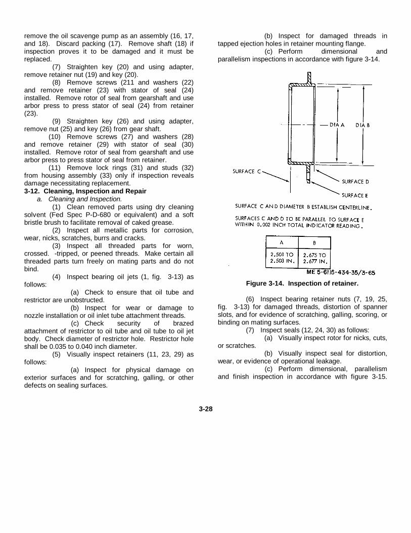
remove the oil scavenge pump as an assembly (16, 17,and 18). Discard packing (17). Remove shaft (18) ifinspection proves it to be damaged and it must bereplaced.
(7) Straighten key (20) and using adapter,remove retainer nut (19) and key (20).
(8) Remove screws (211 and washers (22)and remove retainer (23) with stator of seal (24)installed. Remove rotor of seal from gearshaft and usearbor press to press stator of seal (24) from retainer(23).
(9) Straighten key (26) and using adapter,remove nut (25) and key (26) from gear shaft.
(10) Remove screws (27) and washers (28)and remove retainer (29) with stator of seal (30)installed. Remove rotor of seal from gearshaft and usearbor press to press stator of seal from retainer.
(11) Remove lock rings (31) and studs (32)from housing assembly (33) only if inspection revealsdamage necessitating replacement.3-12. Cleaning, Inspection and Repair
a. Cleaning and Inspection.(1) Clean removed parts using dry cleaning
solvent (Fed Spec P-D-680 or equivalent) and a softbristle brush to facilitate removal of caked grease.
(2) Inspect all metallic parts for corrosion,wear, nicks, scratches, burrs and cracks.
(3) Inspect all threaded parts for worn,crossed. -tripped, or peened threads. Make certain allthreaded parts turn freely on mating parts and do notbind.
(4) Inspect bearing oil jets (1, fig. 3-13) asfollows:
(a) Check to ensure that oil tube andrestrictor are unobstructed.
(b) Inspect for wear or damage tonozzle installation or oil inlet tube attachment threads.
(c) Check security of brazedattachment of restrictor to oil tube and oil tube to oil jetbody. Check diameter of restrictor hole. Restrictor holeshall be 0.035 to 0.040 inch diameter.
(5) Visually inspect retainers (11, 23, 29) asfollows:
(a) Inspect for physical damage onexterior surfaces and for scratching, galling, or otherdefects on sealing surfaces.
(b) Inspect for damaged threads intapped ejection holes in retainer mounting flange.
(c) Perform dimensional andparallelism inspections in accordance with figure 3-14.
Figure 3-14. Inspection of retainer.
(6) Inspect bearing retainer nuts (7, 19, 25,fig. 3-13) for damaged threads, distortion of spannerslots, and for evidence of scratching, galling, scoring, orbinding on mating surfaces.
(7) Inspect seals (12, 24, 30) as follows:(a) Visually inspect rotor for nicks, cuts,
or scratches.(b) Visually inspect seal for distortion,
wear, or evidence of operational leakage.(c) Perform dimensional, parallelism
and finish inspection in accordance with figure 3-15.
3-28
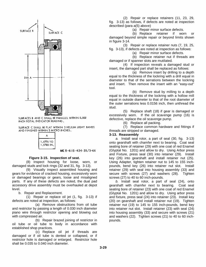
Figure 3-15. Inspection of seat.(8) Inspect housing for loose, worn, or
damaged studs and lock rings (32 and 31, fig. 3-13).(9) Visually inspect assembled housing and
gears for evidence of cracked housing, excessively wornor damaged bearings or gears, loose and misalignedparts. If any of these defects are noted, the dual padaccessory drive assembly must be overhauled at depotlevel.
b. Repair and Replacement.(1) Repair or replace oil jet (1, fig. 3-13) if
defects are noted at inspection, as follows:(a) Remove obstructions from oil tube
and restrictor by passing a length of 0.030 inch diameterpiano wire through restrictor opening and blowing outwith compressed air.
(b) Repair brazed joining of restrictor inoil tube or oil tube to body in accordance withestablished shop practices.
(c) Replace oil jet if threads aredamaged or if oil tube is dented or collapsed, or ifrestrictor hole is damaged or enlarged. Restrictor holeshall be 0.035 to 0.040 inch diameter.
(2) Repair or replace retainers (11, 23, 29,fig. 3-13) as follows, if defects are noted at inspectiondescribed (para a(5) above)
(a) Repair minor surface defects.(b) Replace retainer if worn or
damaged beyond simple repair or beyond limits shownin figure 3-14.
(3) Repair or replace retainer nuts (7, 19, 25,fig. 3-13), if defects are noted at inspection as follows:
(a) Repair minor surface defects.(b) Replace retainer nut if threads are
damaged or if spanner slots are mutilated.(4) If inspection reveals a damaged stud or
insert, the damaged part shall be replaced as follows:(a) Remove insert by drilling to a depth
equal to the thickness of the lockring with a drill equal indiameter to that of the serrations between the lockringand insert. Then remove the insert with an "easy-out"tool.
(b) Remove stud by milling to a depthequal to the thickness of the lockring with a hollow millequal in outside diameter to that of the root diameter ofthe outer serrations less 0.0156 inch, then unthread thestud.
(5) Replace shaft (18) if gear is damaged orexcessively worn. If the oil scavenge pump (16) isdefective, replace the oil scavenge pump.
(6) Replace all packing.(7) Replace common hardware and fittings if
threads are stripped or damaged.3-13. Reassembly
a. Install seal rotor, a part of seal (30, fig. 3-13)onto gearshaft with chamfer next to bearing. Coat sealseating bore of retainer (29) with one coat of red Enamel(Glyptal No. 1201) and allow to dry. Using Arbor pressand Fixture, press seal (30) into retainer (29). Installkey (26) into gearshaft and install retainer nut (25).Using Adapter, tighten retainer nut to 145 to 155 inch-pounds, bend key (26) into retainer nut slot. Installretainer (29) with seal into housing assembly (33) andsecure with screws (27) and washers (28). Tightenscrews (27) to 40 to 60 inch-pounds.
b. Install seal rotor, a part of seal (24), ontogearshaft with chamfer next to bearing. Coat sealseating bore of retainer (23) with one coat of red Enamel(Glyptal No. 1201) and allow to dry. Using arbor pressand fixture, press seal (24) into retainer (23). Install key(20) on gearshaft and install retainer nut (19). Tightenretainer nut (19) to 145 to 155 inch-pounds, bend keyinto retainer nut slot. Install retainer (23) with seal (24)into housing assembly (33) and secure with screws (21)and washers (22). Tighten screws (21) to 40 to 60 inch-pounds.
3-29
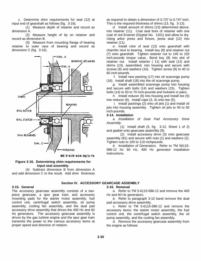
c. Determine shim requirements for seal (12) atinput end of gearshaft as follows (fig. 3-16).
(1) Measure depth of retainer and record asdimension A.
(2) Measure height of lip on retainer andrecord as dimension B.
(3) Measure from mounting flange of bearingretainer to outer race of bearing and record asdimension C (fig. 3-16).
Figure 3-16. Determining shim requirements forinput seal assembly.
(4) Subtract dimension B from dimension Aand add dimension C to the result. Add shim thickness
as required to obtain a dimension of 0.737 to 0.747 inch.This is the required thickness of shims (13, fig. 3-13).
d. Install amount of shims (13) determined above,into retainer (11). Coat seal bore of retainer with onecoat of red Enamel (Glyptal No. 1201) and allow to dry.Using arbor press and fixture, press seal (12) intoretainer (11).
e. Install rotor of seal (12) onto gearshaft withchamfer next to bearing. Install key (8) and retainer nut(7) onto gearshaft. Tighten retainer nut to 145 to 155inch-pounds torque value., Bend key (8) into slot ofretainer nut. Install retainer ( 11) with seal (12) andshims (13), assembled, into housing and secure withscrews (9) and washers (10). Tighten screw (9) to 40 to60 inch-pounds.
f. Install new packing (17) into oil scavenge pump(16). Install shaft (18) into the oil scavenge pump.
g. Install assembled scavenge pump into housingand secure with bolts (14) and washers (15). Tightenbolts (14) to 50 to 70 inch-pounds and lockwire in pairs.
h. Install reducer (6) into housing and install tee (5)into reducer (6). Install caps (3, 4) onto tee (5).
i. Install packings (2) onto oil jets (1) and install oiljets into housing assembly. Tighten oil jets to 40 to 60inch-pounds.3-14. Installation
a. Installation of Dual Pad Accessory DriveAssembly.
(1) Install shaft (5, fig. 3-12, Sheet 1 of 2)and gasket onto gearcase assembly (9).
(2) Install accessory drive (3) onto gearcaseassembly (81) and secure with nuts (1) and washers (2).Tighten nuts to 100 to 110 inchpounds.
b. Installation of Generators. Refer to TM 56115-586-12 for 60 Hz, 400 Hz generator installationinstructions.
Section IV. ACCESSORY GEARCASE ASSEMBLY3-15. GeneralThe accessory gearcase assembly consists of a two-piece gearcase, a spur gear train, and accessorymounting pads for the starter motor assembly, fuelcontrol unit, centrifugal switch assembly, oil pumpassembly, cooling fan assembly, and the dual padaccessory drive assembly that drives the 400 Hz and 60Hz generators. The accessory gearcase assembly isdriven by the gas turbine engine and the spur gear traintransmits the power to the various accessory items atproper speed and direction of rotation.
3-16. Removala. Refer to TM 5-6115-586-12 and remove the 400
Hz and 60 Hz generators.b. Refer to paragraph 3-10 band remove the dual
pad accessory drive assembly.c. Refer to TM 5-6115-586-12 and remove the
accessory items: the starter motor assembly, the fuelcontrol unit, the centrifugal switch assembly, the oilpump assembly, and the cooling fan assembly.
d. Remove the accessory gearcase assembly fromthe engine as follows:
3-30
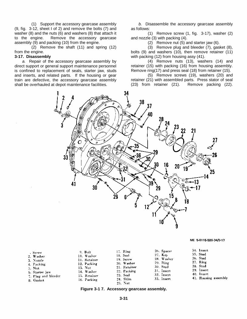
(1) Support the accessory gearcase assembly(9, fig. 3-12, sheet I of 2) and remove the bolts (7) andwasher (8) and the nuts (6) and washers (8) that attach itto the engine. Remove the accessory gearcaseassembly (9) and packing (10) from the engine.
(2) Remove the shaft (11) and spring (12)from the engine.3-17. Disassembly
a. Repair of the accessory gearcase assembly bydirect support or general support maintenance personnelis confined to replacement of seals, starter jaw, studsand inserts, and related parts. If the housing or geartrain are defective, the accessory gearcase assemblyshall be overhauled at depot maintenance facilities.
b. Disassemble the accessory gearcase assemblyas follows:
(1) Remove screw (1, fig. 3-17), washer (2)and nozzle (3) with packing (4).
(2) Remove nut (5) and starter jaw (6).(3) Remove plug and bleeder (7), gasket (8),
bolts (9) and washers (10), then remove retainer (11)with packing (12) from housing assy (41).
(4) Remove nuts (13), washers (14) andretainer (15) with packing (16) from housing assembly.Remove ring(17) and press seal (18) from retainer (15).
(5) Remove screws (19), washers (20) andretainer (21) with assembled parts. Press stator of seal(23) from retainer (21). Remove packing (22).
Figure 3-1 7. Accessory gearcase assembly.
3-31
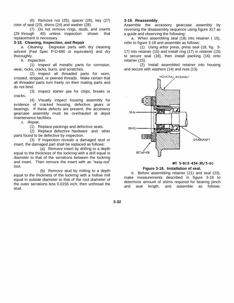
(6) Remove nut (25), spacer (26), key (27)rotor of seal (23), shims (24) and washer (28).
(7) Do not remove rings, studs, and inserts(29 through 40) unless inspection shows thatreplacement is necessary.3-18. Cleaning, Inspection, and Repair
a. Cleaning. Degrease parts with dry cleaningsolvent (Fed Spec P-D-680 or equivalent) and drythoroughly.
b. Inspection.(1) Inspect all metallic parts for corrosion,
wear, nicks, cracks, burrs, and scratches.(2) Inspect all threaded parts for worn,
crossed, stripped, or peened threads. Make certain thatall threaded parts turn freely on their mating parts anddo not bind.
(3) Inspect starter jaw for chips, breaks orcracks.
(4) Visually inspect housing assembly forevidence of cracked housing, defective gears orbearings. If these defects are present, the accessorygearcase assembly must be overhauled at depotmaintenance facilities.
c. Repair.(1) Replace packings and defective seals.(2) Replace defective hardware and other
parts found to be defective by inspection.(3) If inspection reveals a damaged stud or
insert, the damaged part shall be replaced as follows:(a) Remove insert by drilling to a depth
equal to the thickness of the lockring with a drill equal indiameter to that of the serrations between the lockringand insert. Then remove the insert with an "easy-out"tool.
(b) Remove stud by milling to a depthequal to the thickness of the lockring with a hollow millequal in outside diameter to that of the root diameter ofthe outer serrations less 0.0156 inch, then unthread thestud.
3-19. ReassemblyAssemble the accessory gearcase assembly byreversing the disassembly sequence using figure 317 asa guide and observing the following:
a. When assembling seal (18) into retainer ( 15),refer to figure 3-18 and assemble as follows:
(1) Using arbor press, press seal (18, fig. 3-17) into retainer (15) and install ring (17) in retainer (15)to secure seal (18), then install packing (16) ontoretainer (15).
(2) Install assembled retainer into housingand secure with washers (14) and nuts (13).
Figure 3-18. Installation of seal.b. Before assembling retainer (21) and seal (23),
make measurements described in figure 3-19 todetermine amount of shims required for bearing pinchand seal length, and assemble as follows:
3-32
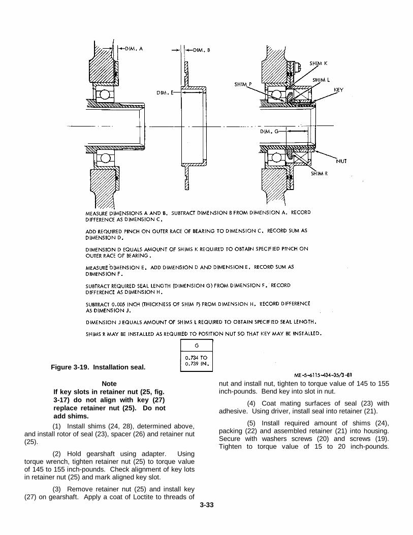
NoteIf key slots in retainer nut (25, fig.3-17) do not align with key (27)replace retainer nut (25). Do notadd shims.(1) Install shims (24, 28), determined above,
and install rotor of seal (23), spacer (26) and retainer nut(25).
(2) Hold gearshaft using adapter. Usingtorque wrench, tighten retainer nut (25) to torque valueof 145 to 155 inch-pounds. Check alignment of key lotsin retainer nut (25) and mark aligned key slot.
(3) Remove retainer nut (25) and install key(27) on gearshaft. Apply a coat of Loctite to threads of
nut and install nut, tighten to torque value of 145 to 155inch-pounds. Bend key into slot in nut.
(4) Coat mating surfaces of seal (23) withadhesive. Using driver, install seal into retainer (21).
(5) Install required amount of shims (24),packing (22) and assembled retainer (21) into housing.Secure with washers screws (20) and screws (19).Tighten to torque value of 15 to 20 inch-pounds.
3-33
Figure 3-19. Installation seal.
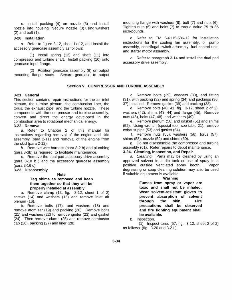
c. Install packing (4) on nozzle (3) and installnozzle into housing. Secure nozzle (3) using washers(2) and bolt (1).3-20. Installation
a. Refer to figure 3-12, sheet I of 2, and install theaccessory gearcase assembly as follows:
(1) Install spring (12) and shaft (11) intocompressor and turbine shaft. Install packing (10) ontogearcase input flange.
(2) Position gearcase assembly (9) on outputmounting flange studs. Secure gearcase to output
mounting flange with washers (8), bolt (7) and nuts (6).Tighten nuts (6) and bolts (7) to torque value 75 to 85inch-pounds.
b. Refer to TM 5-6115-586-12 for installationinstructions for the cooling fan assembly, oil pumpassembly, centrifugal switch assembly, fuel control unit,and starter motor assembly.
c. Refer to paragraph 3-14 and install the dual padaccessory drive assembly.
Section V. COMPRESSOR AND TURBINE ASSEMBLY
3-21. GeneralThis section contains repair instructions for the air inletplenum, the turbine plenum, the combustion liner, thetorus, the exhaust pipe, and the turbine nozzle. Thesecomponents with the compressor and turbine assembly,convert and direct the energy developed in thecombustion area to rotational mechanical energy.3-22. Removal
a. Refer to Chapter 2 of this manual forinstructions regarding removal of the engine and skidassembly (para 2-11) and removal of the engine fromthe skid (para 2-12).
b. Remove wire harness (para 3-2 b) and plumbing(para 3-3b) as required to facilitate maintenance.
c. Remove the dual pad accessory drive assembly(para 3-10 b ) and the accessory gearcase assembly(para 3-16 c).3-23. Disassembly
NoteTag shims as removed and keepthem together so that they will beproperly installed at assembly.
a. Remove clamp (13, fig. 3-12, sheet 1 of 2)screws (14) and washers (15) and remove inlet airplenum (16).
b. Remove bolts (17), and washers (18) andremove atomizer (19) and packing (20). Remove bolts(21) and washers (22) to remove igniter (23) and gasket(24). Then remove clamp (25) and remove combustorcap (26), packing (27) and liner (28).
c. Remove bolts (29), washers (30), and fitting(31), with packing (32) and spring (34) and packings (36,37) installed. Remove gasket (39) and packing (33).
d. Remove bolts (40, 41, fig. 3-12, sheet 2 of 2),washers (42), shims (43, 44) and flange (45). Removenuts (46), bolts (47, 48), and washers (49).
e. Remove plenum (50) and gasket (51) and shims(52). Using wrench (special tool; see table 21), removeexhaust pipe (53) and gasket (54).
f. Remove nuts (55), washers (56), torus (57),shims (58), nozzle (59) and shims (60).
g. Do not disassemble the compressor and turbineassembly (61). Refer repairs to depot maintenance.3-24. Cleaning, Inspection, and Repair
a. Cleaning. Parts may be cleaned by using anapproved solvent in a dip tank or use of spray in apositive outside ventilated spray booth. Vapordegreasing or soap cleaning solution may also be usedif suitable equipment is available.
WarningFumes from spray or vapor aretoxic and shall not be inhaled.Wear solvent-resistant gloves toprevent absorption of solventthrough the skin. Fireprecautions shall be observedand fire fighting equipment shallbe available.
b. Inspection.(1) Inspect torus (57, fig. 3-12, sheet 2 of 2)
as follows: (fig. 3-20 and 3-21.)
3-34
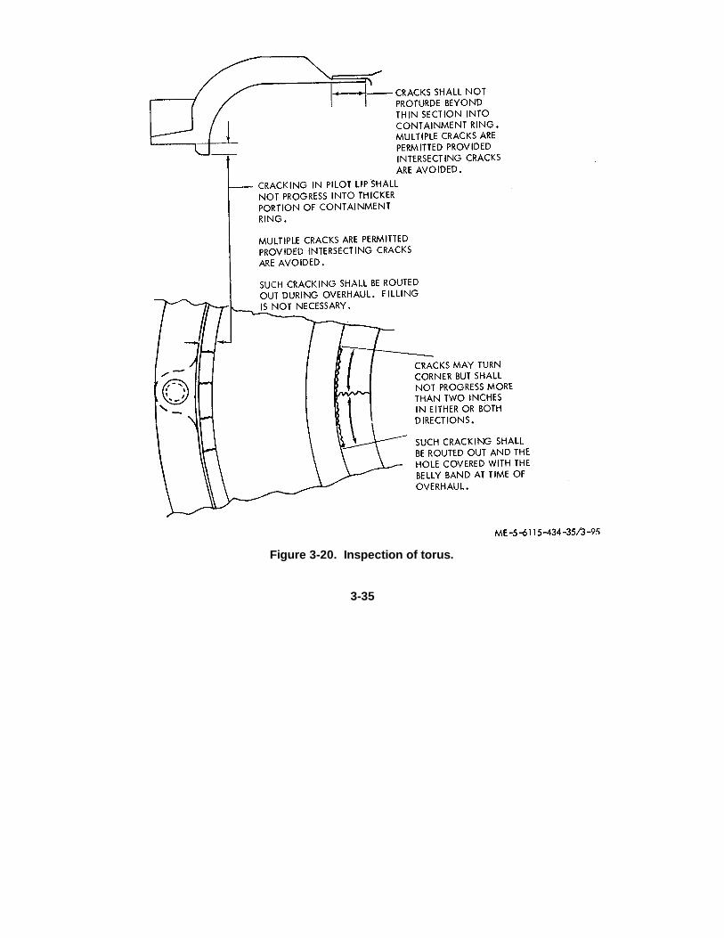
Figure 3-20. Inspection of torus.
3-35
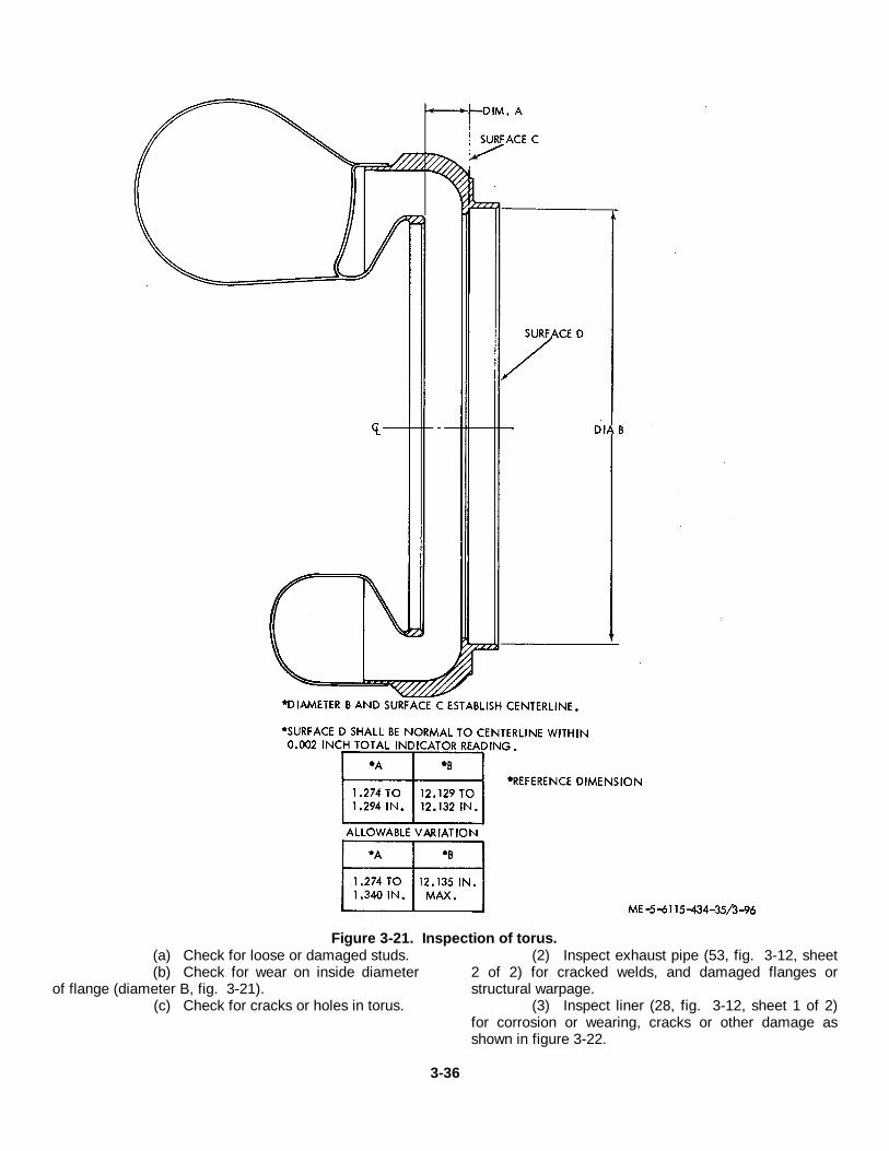
Figure 3-21. Inspection of torus.(a) Check for loose or damaged studs.(b) Check for wear on inside diameter
of flange (diameter B, fig. 3-21).(c) Check for cracks or holes in torus.
(2) Inspect exhaust pipe (53, fig. 3-12, sheet2 of 2) for cracked welds, and damaged flanges orstructural warpage.
(3) Inspect liner (28, fig. 3-12, sheet 1 of 2)for corrosion or wearing, cracks or other damage asshown in figure 3-22.
3-36
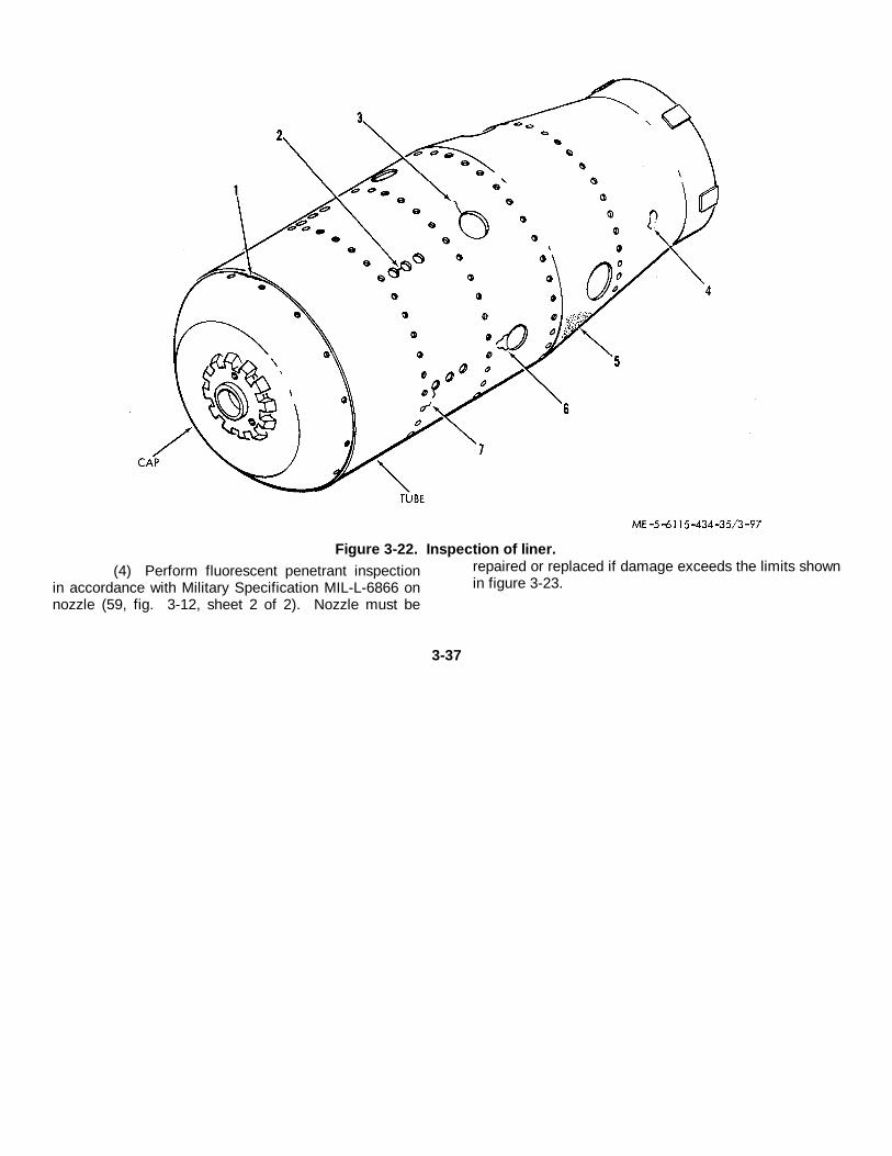
Figure 3-22. Inspection of liner.(4) Perform fluorescent penetrant inspection
in accordance with Military Specification MIL-L-6866 onnozzle (59, fig. 3-12, sheet 2 of 2). Nozzle must be
repaired or replaced if damage exceeds the limits shownin figure 3-23.
3-37
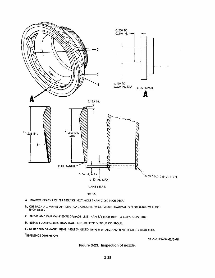
Figure 3-23. Inspection of nozzle.
3-38
c. Repair.(1) Repair liner (28, fig. 3-12, sheet 1 of 2)
as follows:(a) All cracks are to be repaired by
welding except as noted. Weld in accordance withMilitary Specification MIL-W-8611, using N-155 filler rodconforming to Military Specification MIL-R-5031, class9.
(b) Weld cracks connecting any twoholes in accordance with Military Specification MIL-W6858.
(c) Weld any cracks over 1/8 inch longin accordance with Military Specification MIL-W6858.
(d) Replace liner, if buckling is greaterthan 1/8 inch deformation.
(e) Replace liner, if metal thickness isless than 0.030 inch due to corrosion or wear.
(f) If practical, weld any group ofcracks which could cause breaking away of material inaccordance with Military Specification MIL-W6858,otherwise replace liner.
(g) Weld any cracks separated by lessthan ¼ inch of material in accordance with MilitarySpecification MIL-W-6858.
(h) Remove and replace damagedcooling skirts. Weld cooling skirts in accordance withMilitary Specification MIL-W-6811, using N-155 filler rodconforming to Military Specification MIL-R-5031, Class9.
(2) Repair nozzle (131) as follows.(a) Remove cracks or feathering not
more than 0.060 inch deep on trailing edge of vanes asshown in figure 3-22. Rework of one or more vanesmay be performed without necessarily reworking allvanes. When cracks or feathering require removal ofmaterial of more than 0.060 to 0.130 inch deep ontrailing edge of vane, all vanes shall be cut back anidentical amount.
(b) Repair erosion of vane leading edgethat is less than 1/8 inch deep by blending and fairing toblade contour.
(c) Repair scoring that is less than0.030 inch deep on shroud by blending to shroudcontour.
(d) Repair damaged or worn stud bybuilding up with weld using inert gas shielded tungstenarc and Rene 41 or 718 welding rod. Grind todimensions specified in figure 3-23.
(3) Repair exhaust pipe (53, fig. 3-12, sheet2 of 2) as follows:
(a) Reweld cracked welds per MilitarySpecification MIL-W,8611, using N-155 Weld rod.
(b) If threads of bolt holes are damagedbeyond repair, plug weld using N-155 weld rod, drill newholes through plug weld 0.0211 to 0.219 inch. Countersink 115° to 125° by 0.25 to 0.28 inch diameter. Tapwith ¼ by 28 UNF-3B tap. Deburr and inspect.
(4) Repair turbine plenum (50, fig. 3-12,sheet 2 of 2) as described in figure 3-24.
3-39
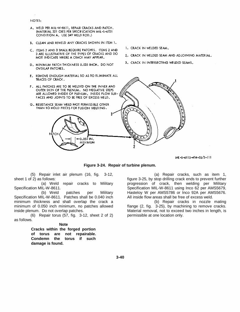
Figure 3-24. Repair of turbine plenum.
(5) Repair inlet air plenum (16, fig. 3-12,sheet 1 of 2) as follows:
(a) Weld repair cracks to MilitarySpecification MIL-W-8611.
(b) Weld patches per MilitarySpecification MIL-W-8611. Patches shall be 0.040 inchminimum thickness and shall overlap the crack aminimum of 0.050 inch minimum, no patches allowedinside plenum. Do not overlap patches.
(6) Repair torus (57, fig. 3-12, sheet 2 of 2)as follows.
NoteCracks within the forged portionof torus are not repairable.Condemn the torus if suchdamage is found.
(a) Repair cracks, such as item 1,figure 3-25, by stop drilling crack ends to prevent furtherprogression of crack, then welding per MilitarySpecification MIL-W-8611 using Inco 62 per AMS5679,Hasteloy W per AMS5786 or Inco 92A per AMS5676.All inside flow areas shall be free of excess weld.
(b) Repair cracks in nozzle matingflange (2, fig. 3-25), by machining to remove cracks.Material removal, not to exceed two inches in length, ispermissible at one location only.
3-40
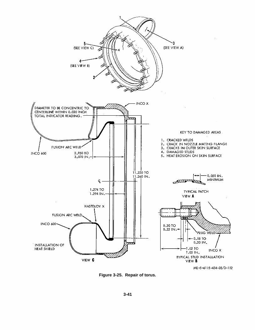
Figure 3-25. Repair of torus.
3-41
(c) Repair cracks in torus skin (3, fig.325) by patching. Remove sufficient material toeliminate all trace of crack. Patch material shall be Inco600 and shall be 0.043 inch (minimum). Weld patcheson both the inner and outer skin surfaces per MilitarySpecification MIL-W-8611, using weld rod as specifiedin (1) above. Do not overlap patches. Maintainminimum overlap of patch on torus skin, as shown inview A, figure 3-25. Inside flow surfaces and joints shallbe free of excess weld.
NoteRecent versions of the toruscontain 10 studs only.Consequently stud repair may beperformed on alternating studs(20 stud version) and removal, ifdesired, of remainder.
(d) If inspection revealed damagedstuds, cut off damaged studs flush with torus surface.Drill through remainder of old stud. Countersink 118 to122 degrees by 0.530 inch diameter (maximum ) toremove tack welds. Install new studs as shown in viewB and plug weld per Military Specification MIL-W-8611,using Inconel 69 weld rod.
(7) Replace all packings and replace anyhardware found to be stripped or damaged.
(8) Replace all other defective parts.3-25. Reassembly
NoteBe certain that shims (58, 60, fig.3-12, sheet 2) are installed exactlyas removed. The determination ofthickness of shims requiresspecial tools and facilities notnormally available to directsupport and general supportmaintenance personnel.
a. Install nozzle (59) and shims (60).b. Install torus (57) with shims (58). Secure with
nuts (55) and washers (56). Tighten nuts, using wrench,to torque value of 50 to 70 inch-pounds. Coat threads ofexhaust pipe (53) with high temperature compound.
c. Coat threads of transfer tube (38) withlubricating compound (Liqui-Moly, Grade NV) and installwith new gasket (39). Tighten tube to torque value of385 to 440 inch-pounds.
d. Install tube (35) with new packings (36, 37).Install fitting (31) with spring (34) and new packings (31,32). Install bolts (29) and washers (30). Tighten bolts(29) to torque value of 50 to 70 inch-pounds.
e. Set turbine plenum (50) down onto supportassembly and use tool to tighten tail pipe (53). Alignturbine plenum. Remove turbine plenum and installgasket (51). Reinstall turbine plenum into previouslyaligned position. Use feeler gauge to measure gap fromturbine plenum rear flange to tail pipe (53) rear flange.Subtract 0.015 to 0.025 inch from measurement andrecord for later shimming operation.
f. Remove turbine plenum and gasket. Install 2alignment pins in rear flange of tail pipe, install shims(52) determined (para 3) above, over alignment pins.Apply a light coat of petrolatum to both sides of gasket,reinstall gasket and turbine plenum into previousorientation. Install flange (45) and shims (43, 44) to rearface of turbine plenum and on alignment pins.
g. Install bolts (47, 48), washers (49) and nuts (46).Torque bolts to a value of 50 to 70 inchpounds. Installbolts (40, 41) and washers (42) into flange (45). Torquebolts to a value of 90 to 110 inch-pounds.
h. Install liner (28, fig. 3-12, sheet 1 of 2). Installcombustor cap (26) with packing (27).
i. Install igniter (23) and gasket (24) with bolts (21)and washers (22). Install packing (20) and atomizer (19)with bolts (17) and washers (18).
j. Install inlet air plenum (16) with screws (14),washers (15) and clamp (13).3-26. Installation
a. Install accessory gearcase assembly (para 320a), dual pad accessory drive assembly (para 314),plumbing (3-3d) and wiring (3-2 h).
b. Refer to paragraphs 2-12 and 2-11 forinstructions for installation of engine to skid andinstallation of engine and skid assembly respectively.
3-42
CHAPTER 4
REPAIR OF SKID ASSEMBLY
4-1. Generala. The major components of the skid assembly are
the skid, oil tank, fuel tank, fuel filter, fuel pump, fuelfloat tank and plumbing installation.
b. Prior to performing any repair to the abovelisted items, remove the major components of theengine and skid assembly (para 2-12).
c. Refer to Chapter 5 of this manual for repairinstructions on skid assembly electrical wire harnesses.4-2. Hose and Tube Assemblies and PlumbingFittings
a. General. The hose and tube assemblies andplumbing fittings provide interconnection of pneumatic,fuel, and oil systems components. The hose assembliesconsist of metallic braid protected hoses withappropriate end fittings permanently secured to the hoseand metallic braid. The tube assemblies consist offormed metal tubes with standard fittings to provideorientation of hose and tube assemblies to thecomponents.
b. Removal. Refer to paragraph 3-3 of this manualfor hose and tube assemblies removal instructions.
c. Cleaning, Inspection and Repair.(1) Clean hose and tube assemblies and
plumbing fittings with an approved cleaning solvent anddry thoroughly with filtered compressed air.
(2) Inspect all threaded parts for stripped,crossed, or peened threads. If threads are damagedbeyond simple repair, replace the part.
(3) Inspect hose assemblies for cracks,breaks, chafing and damage to hose interior. Ifdamaged, replace hose assembly.
(4) Inspect tube assemblies for kinks, bends,cracks, or other damage which might restrict flow orresult in leakage. If damaged, replace tube assembly.
(5) Inspect plumbing fittings for cracks orclogged passages. Clean clogged passages andreplace cracked fittings.
(6) Replace all gaskets and packings at eachoverhaul regardless of condition.
d. Installation. Refer to paragraph 3-3 of thismanual for hose and tube assembly installationinstructions.4-3. Oil Tank Assembly
a. General. The oil tank assembly is mounted onthe skid in a cradle. The oil tank is the oil supplyreservoir for the power unit.
b. Removal. Refer to TM 5-6115.586-12 for oiltank removal instructions.
c. Cleaning, Inspection and Repair.(1) Clean oil tank assembly with an approved
solvent, drain thoroughly and dry with filteredcompressed air.
(2) Inspect all threaded areas for stripped,crossed or peened threads. If threads are damagedbeyond simple repair, replace part.
(3) Inspect tank for punctures, ruptures,broken welds and looseness of fittings.
(4) Reweld broken welds in accordance withMilitary Specification MIL-W-8604.
(5) Pressure test oil tank after repair at 5 psigcontrolled pressure for five minutes. No leakage isallowed.
d. Installation. Refer to TM 5-6115-586-12 for oiltank installation instructions.4-4. Fuel Boost Pump
a. General. The fuel boost pump furnishes fuelunder pressure to the engine from the external source.The fuel boost pump is mounted on a mounting plate onthe skid.
b. Removal. Refer to TM 5-6115-586-12 for fuelboost pump, removal instructions.
c. Disassembly. Remove the four screws (1, fig.4-1 ) to remove the pump (2). Remove the four bolts (3)and washers (4) to remove the stator (5), coupling (6),and gasket (7) from motor (11). Do not removereceptacle (10) unless damaged. If damaged, removethe lockwire (8) and the four screws (9). Unsolder theelectrical wires that connect to the receptacle andremove damaged receptacle (10).
4-1

Figure 4-1. Fuel boost pump, exploded view.
4-2
d. Cleaning, Inspection and Repair.(1) Clean fuel boost pump parts using an
approved solvent. Dry with filtered compressed air.(2) Visually inspect all parts for breakage,
wear, corrosion, or other forms of damage.(3) Replace parts damaged beyond simple
repair.(4) If receptacle is damaged, replace with
new receptacle and resolder electrical wiring inaccordance with MIL-S-6872 using solder SN60-WRP2per Fed Spec QQ-S-571. After reinstalling screws (9),install new lockwire (8) in accordance with MS33540.
e. Assembly. Assemble the fuel boost pump byreversing the disassembly sequence given in paragraphc, above while observing special instructions onsoldering given in paragraph d, (4), above.
f. Installation. Refer to TM 5-6115-586-12 for fuelboost pump installation instructions.4-5. Fuel Filter
a. The fuel filter is mounted on an upright bracketon the skid assembly. The fuel filter is locateddownstream of the skid mounted fuel tank in the fuelsystem.
b. Refer to TM 5-6115-586-12 for removal,disassembly, cleaning, inspection, repair, assembly, andreinstallation instructions.4-6. Fuel Tank
a. General. The fuel tank is mounted in a cradleon the skid. The fuel tank acts as a reservoir andcontains enough fuel to permit unit operation whileswitching from one external fuel source to another.
b. Removal. Refer to TM 5-6115-586-12 for fueltank removal instructions.
c. Cleaning, Inspection and Repair.(1) Flush fuel tank with an approved solvent
and dry with filtered compressed air.(2) Inspect fuel tank fitting bosses for
crossed, stripped or peened threads.(3) Inspect for cracks, ruptures or punctures.(4) Repair bosses using simple repair,
replace tank if damaged beyond simple repair or ifinspection requirements are not met.4-7. Air Inlet Duct and Screen Assembly
a. General.(1) The screen assembly prevents large
objects from entering the air inlet duct.(2) The air inlet duct directs air from the
enclosure air inlet to the air inlet plenum assembly.b. Removal. Refer to paragraph 2-11 of this
manual to remove the air inlet duct and screenassembly.
c. Disassembly. Do not disassemble the air inletduct unless inspection reveals damage. If disassemblyis required, follow sequence of index numbers I through20 assigned to figure 4-2.
d. Cleaning, Inspection and Repair.(1) Clean the air inlet duct using an approved
solvent.(2) Inspect for cracks, tears, holes or dents.(3) Inspect riveted components for security
and damage.(4) Inspect seal for security and
serviceability.(5) Inspect nut plates for security and
damage.(6) Inspect screen for broken wires.
4-3
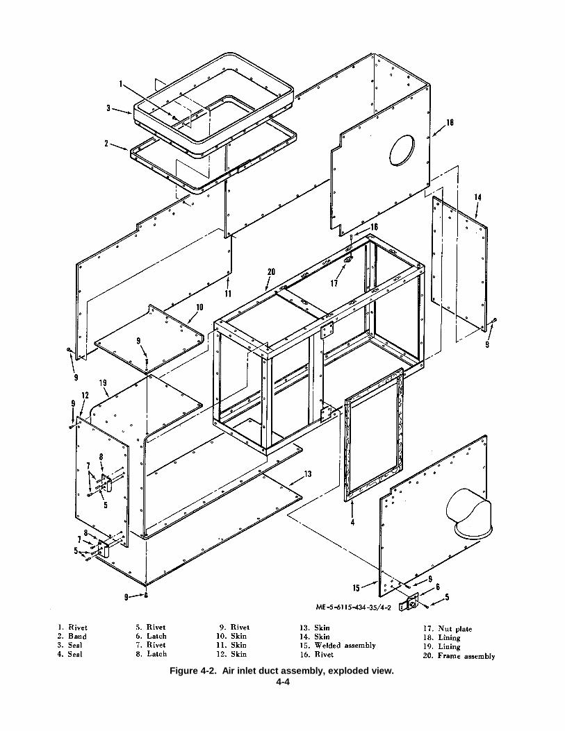
Figure 4-2. Air inlet duct assembly, exploded view.4-4
(7) Inspect for screen separation, broken orcracked laminate.
(8) Replace screen assembly if damagedbeyond simple repair.
(9) Repair cracks using simple shop repair.(10) Patch holes and tears using simple shop
repair.(11) Replace loose or damaged rivets.(12) Replace seals using adhesive.(13) Replace damaged nut plates.(14) If air inlet duct is damaged beyond simple
repair, replace the entire assembly.e. Assembly. Assemble air inlet duct assembly in
reverse order of disassembly procedures given inparagraph 4-7 c above.
f. Reinstallation. Refer to paragraph 2-11 toreinstall the air inlet duct and screen assembly.4-8. Air Inlet Plenum Assembly
a. General. The air inlet plenum is skid mountedand directs air to the engine air inlet plenum assembly.To remove the lower portion, simply remove thehardware which attaches it to the skid.
b. Disassembly. Do not disassemble the air inletplenum unless inspection reveals damage. If damage isindicated, disassemble by following sequence of indexnumbers, 1 through 20, assigned to figure 4-3, and 1through 18, assigned to figure 4-4
4-5
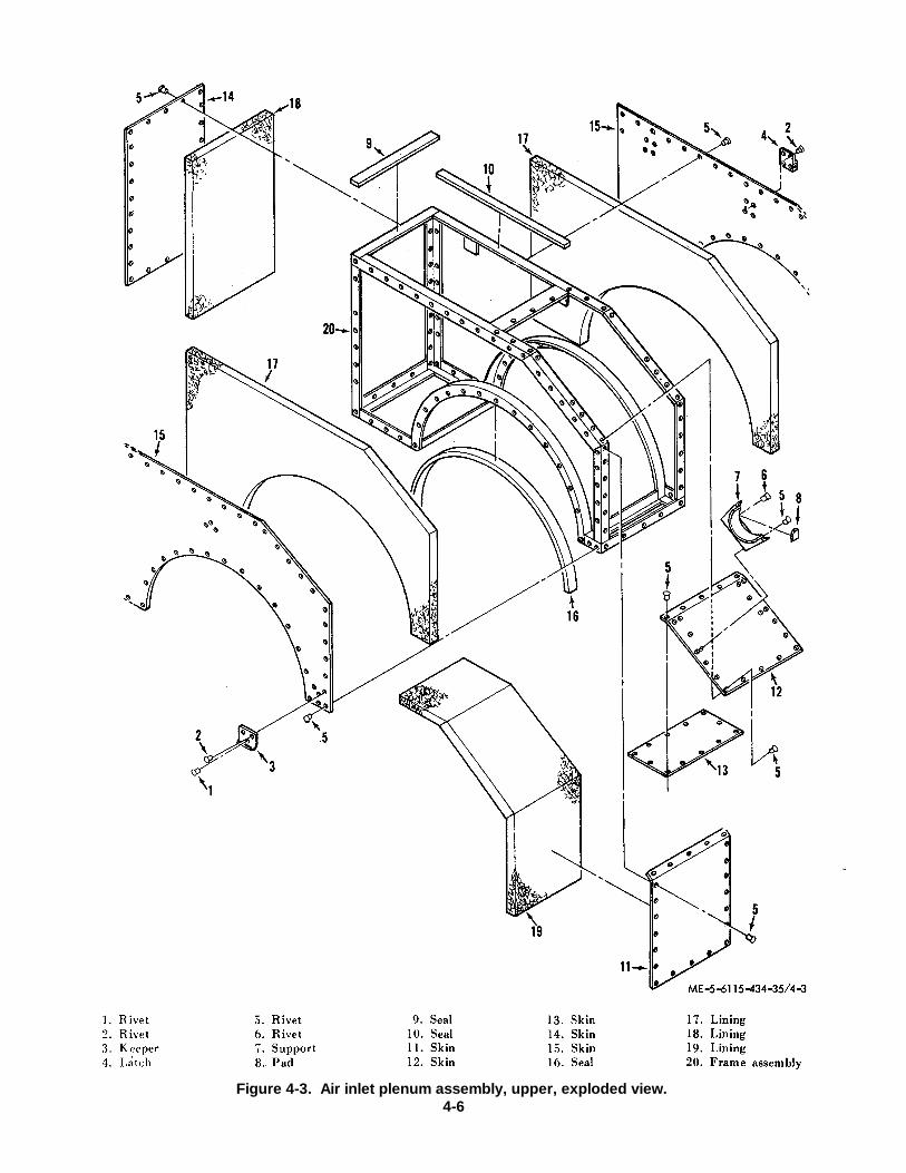
Figure 4-3. Air inlet plenum assembly, upper, exploded view.4-6

Figure 4-4. Air inlet plenum assembly, lower, exploded view4-7
c. Cleaning, Inspection and Repair.
(1) Clean plenum using an approved solventand a lint free rag.
(2) Visually inspect for cracks, holes, ordents.
(3! Inspect seals for security and abnormalwear.
(4) Inspect welds for breaks and cracks.
(5) Inspect riveted components for securityand damage.
(6) Repair dents by cold working using goodshop practice.
(7) Repair cracks using simple shop repair.
(8) Patch hole using simple shop repair.
(9) Replace loose or damaged rivets inaccordance with good shop practice.
(10) Replace loose or damaged seals usingadhesive.
d. Assembly. Assemble air inlet plenum assemblyin reverse order of disassembly procedures(para 4-8 c. above).
e. Reinstallation. Replace the lower portion byattaching it to the skid with its hardware. Attachthe upper portion as instructed in paragraph 2-12.
4-9. Heat Shield Assembly
a. General. The heat shield assembly separatesthe engine hot section from the plenum inletassembly.
b. Removal. Refer to paragraph 2-12 to removethe upper portion of the heat shield. To removethe lower portion, simply remove the hardwarewhich attaches it to the skid.
c. Disassembly. Do not disassemble the heatshields unless inspection reveals damage. Ifrequired, disassemble by following thesequence of index numbers, I through 13,assigned to figure 4-5 and 1 through 10,assigned to figure 4-6.
4-8
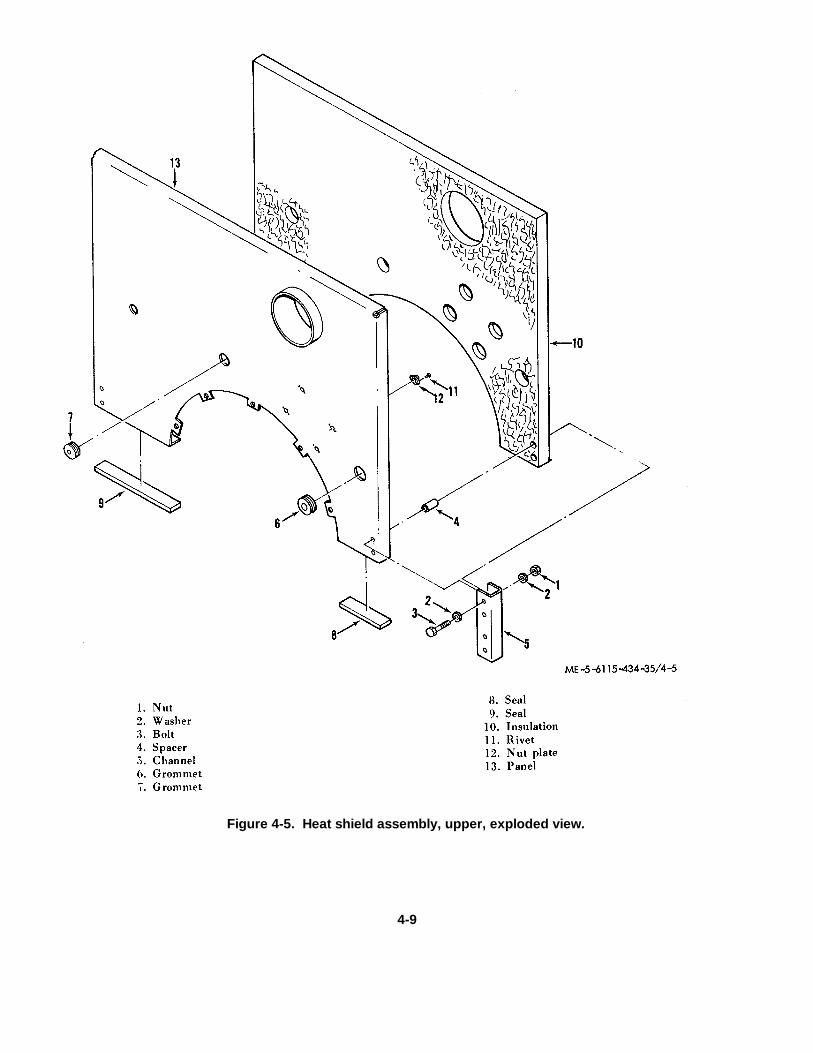
Figure 4-5. Heat shield assembly, upper, exploded view.
4-9

Figure 4-6. Heat shield assembly, lower, exploded view.d. Cleaning, Inspection and Repair.
(1) Clean heat shield using an approvedsolvent and a stiff bristled brush.
NoteDo not get solvent on insulationor seals.(2) Inspect for cracks, tears or holes.
(3) Inspect bolt, spacers, washers and nutssecuring channels for security of installation.
(4) Inspect grommets for security ofinstallation.
(5) Inspect nut plates and all rivetedcomponents for loose rivets or damage to components.
(6) Repair cracks using simple shop repair.
(7) Patch hole or tears using simple shop repair.
(8) Tighten loose bolts and nuts securingchannels.
(9) Replace damaged grommets.
(10) Replace loose or damaged rivets andreplace damaged riveted components.
(11) If heat shields are damaged beyondsimple repair, replace the entire assembly.
e. Assembly. Assemble heat shield assembly inreverse order of disassembly procedures givenin paragraph 4-9 c. above.
f. Reinstallation. Replace the lower portion byattaching it to the skid using the hardware thatattaches it. Replace the upper portion asinstructed in paragraph 2-12.
4-10. Skid Assembly
a. General. The skid assembly mounts the engine,oil tank, fuel boost pump, fuel filter, fuel tankand brackets supporting these units.
b. Disassembly. Do not disassemble skidassembly unless inspection reveals damage. Ifrequired, follow sequence of index numbers, 1through 19 assigned to figure 4-7 and I through11, assigned to figure 4-8 for disassembly.
c. Cleaning, Inspection and Repair.
(1) Clean skid and component parts with anapproved solvent. Dry thoroughly with filteredcompressed air

.(2) Inspect brackets for cracks and breaks.
(3) Inspect brackets for security andserviceability of cushioning material.
(4) Inspect supports for cracks and breaks.Inspect support (18, fig. 4-7) for security andserviceability of cushioning material.
4-11
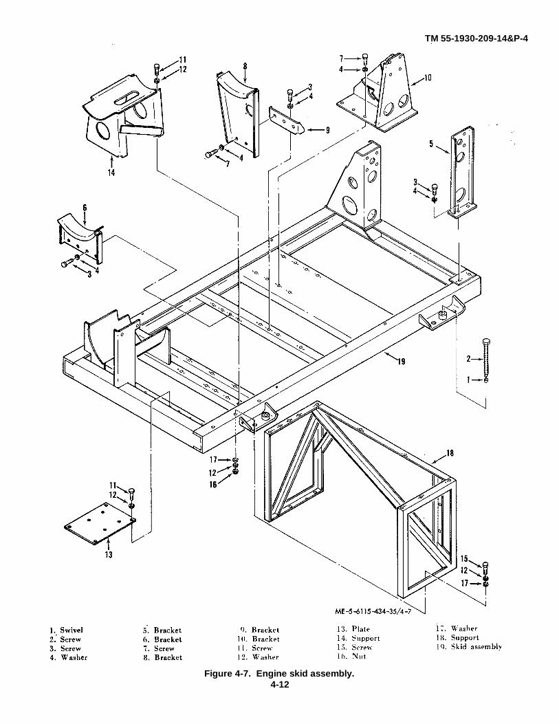
TM 55-1930-209-14&P-4
Figure 4-7. Engine skid assembly.4-12

(5) Inspect the skid for cracked, broken orbent components, security and serviceability of nutplates and screws.
(6) Inspect pads and spacer for damage orabnormal wear.
(7) If skid parts are damaged beyond simplerepair, replace the entire skid.
d. Assembly. Assemble skid assembly in reverseorder of disassembly procedures (para 410 b. above).
4-13
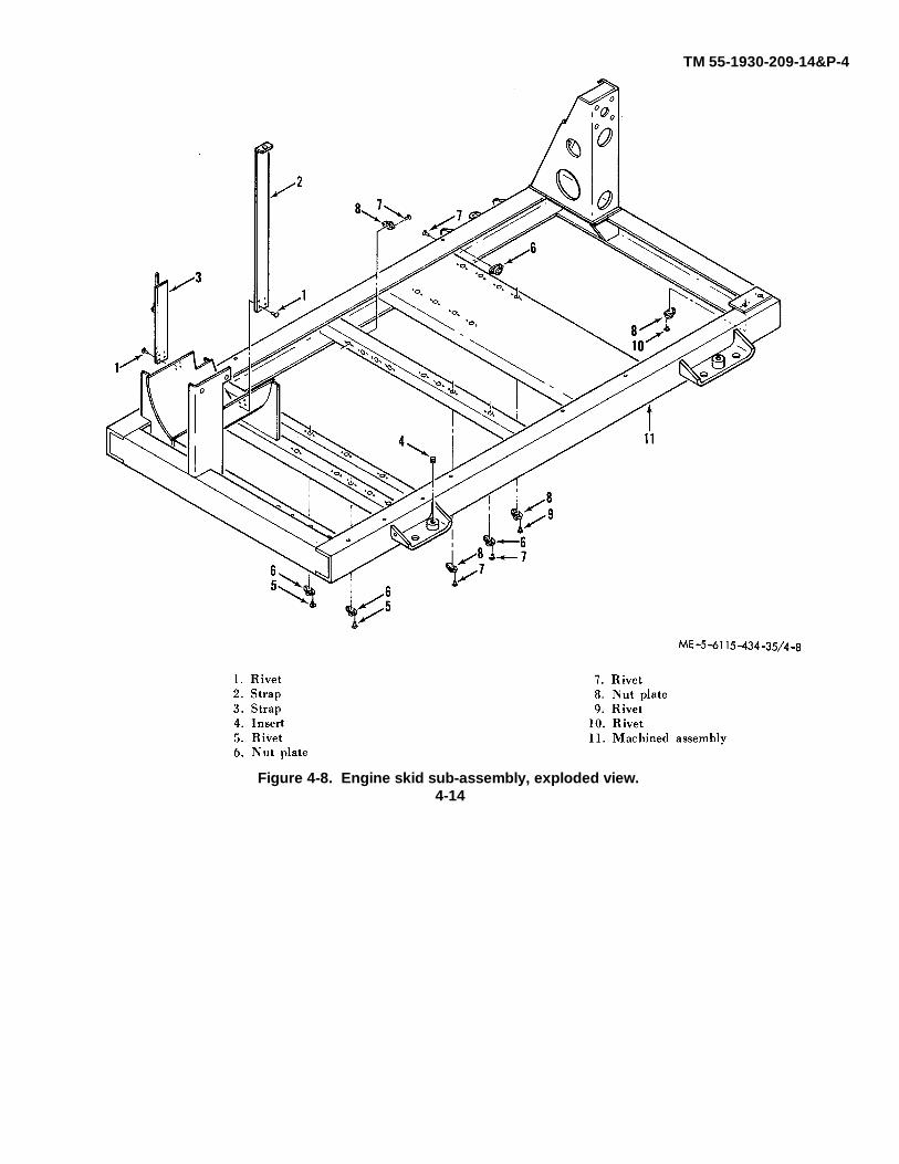
TM 55-1930-209-14&P-4
Figure 4-8. Engine skid sub-assembly, exploded view.4-14
CHAPTER 5REPAIR OF ELECTRICAL COMPONENTS
Section I. POWER PLANT ELECTRICAL INSTALLATION5-1. General
a The power plant electrical installation includesall wire harness assemblies (except those located on theengine and skid), the instrument panel, the conditionedair electrical components panel, the auxiliary power tray,the receptacle panel assembly, and the conditioned airtemperature control panel. These components controland deliver power for the 400 Hz and 60 Hz ACelectrical systems and the DC electrical system.
b. Paragraphs 5-2 through 5-25 contain repairinstructions for the interconnecting wire harnessassemblies. The panel wire harness assemblies areincluded in repair instructions for the panel where theyare located. Repair instructions for all single wireelectrical leads used in the unit are provided inparagraph 5-31.
c. Wiring diagrams for the wire harness and panelassemblies included in this section are provided in TM5-6115-586-12. Refer to the wiring diagrams as an aidto testing, repair, and installation. Wire run charts areprovided in this section for individual wire harnessassemblies. Wires are identified in accordance withMIL-W5088. Refer also to TM 5-6115-586-12 forschematics of the electrical system.
WarningBefore maintenance is performedon any electrical component, thepower plant shall be shut downand shall be disconnected fromanother power plant that is
operating or from any otherelectrical power source. Failureto observe this warning may leadto serious injury or death topersonnel.
5-2. DC Power Branched Wire Harness Assembly(13217E4147)
a. Removal. Refer to figure 5-1; tag anddisconnect the DC power branched wire harnessassembly as follows: (1) Remove the terminal boardcover from terminal board (TB2) located on the inboardwall of the No. I system condenser compartment.
(1) Remove three nuts, screws, and washersand remove the terminal board.
(2) Remove lockwire and disconnectconnector P38 (engine skid wire harness). Removeconnector J38 from the floor of No. 1 system condensercompartment by removing four nuts and screws andeight washers.
(3) Disconnect wires to switches (S27 andS33). Remove lockwires and disconnect the eight "plug-type" wire harness connectors.
(4) Remove six wire harness clamps, notingthe position of the clamps and routing of the wireharness.
(5) Remove the wire harness.
5-1
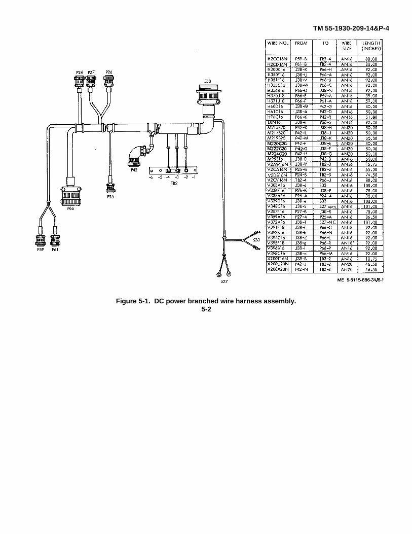
TM 55-1930-209-14&P-4
Figure 5-1. DC power branched wire harness assembly.5-2

b. Disassembly. After inspection and testing,disassemble the wire harness only as required for repairor replacement.
c. Cleaning and Inspection.
(1) Clean wire harness with a clean, lint-freecloth moistened with approved solvent and drythoroughly.
(2) Inspect for damaged or loose connectorpins, terminals, and terminal board studs. Check for anyevidence of burned areas indicating shorts. Inspectwiring for damaged insulation and loose connections.Inspect connectors for damaged or stripped threads.
d. Testing. Refer to the wire run chart in figure 5-1and check individual wires for continuity.
e. Repair. Replacement and Reassembly.
(1) Solder connections will be made inaccordance with MIL-S-6872 using solder typeSN60OWRP2 per Fed Spec QQ-S-571.
(2) Replace defective wires with wire inaccordance with MIL-W-5086, Type II. Wire size andapproximate length in inches is provided in figure 5-1.
(3) If replacement of connector J38 isnecessary, remove potting compound and unsolderelectrical leads. Solder electrical leads toreplacement connector. Fill connector backshell withsilicone rubber sealing compound (501 RTV and
Catalyst 501A, Dow Corning Corp., Midland, Michigan,or equivalent).
(4) If self-clinching cable straps are removedto facilitate repairs, install new cable straps at five inchintervals and all cable breakouts.
f. Installation. Install the wire harness assemblyin reverse order of removal procedure. After installingconnectors, safety wire in accordance with' MS33540using lockwire MS20995C20.
5-3. Power Plant DC Power Branched Wire HarnessAssembly 113217E4153)
a. Removal. Refer to figure 5-2; tag anddisconnect the power plant DC power branched wireharness assembly as follows:
(1) Remove the terminal board cover fromterminal board (TB4) and remove the wire harnesselectrical leads from the terminal board studs.
(2) Remove lockwire and disconnect P52 andP106, then remove connectors J52 and J106 from theinboard wall of the battery access and storagecompartment by removing four nuts and screws andeight washers from each connector.
(3) Remove lockwires and disconnect thethree remaining wire harness connectors. Disconnectthe leads to the air intake door switch (S4).
(4) Remove the four cable clamps, noting theposition of the clamps and routing of the wire harness.
(5) Remove the wire harness.
5-3
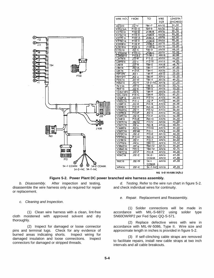
Figure 5-2. Power Plant DC power branched wire harness assembly.b. Disassembly. After inspection and testing,
disassemble the wire harness only as required for repairor replacement.
c. Cleaning and Inspection.
(1) Clean wire harness with a clean, lint-freecloth moistened with approved solvent and drythoroughly.
(2) Inspect for damaged or loose connectorpins and terminal lugs. Check for any evidence ofburned areas indicating shorts. Inspect wiring fordamaged insulation and loose connections. Inspectconnectors for damaged or stripped threads.
d. Testing. Refer to the wire run chart in figure 5-2.and check individual wires for continuity.
e. Repair. Replacement and Reassembly.
(1) Solder connections will be made inaccordance with MIL-S-6872 using solder typeSN60OWRP2 per Fed Spec QQ-S-571.
(2) Replace defective wires with wire inaccordance with MIL-W-5086, Type II. Wire size andapproximate length in inches is provided in figure 5-2.
(3) If self-clinching cable straps are removedto facilitate repairs, install new cable straps at two inchintervals and all cable breakouts.
5-4
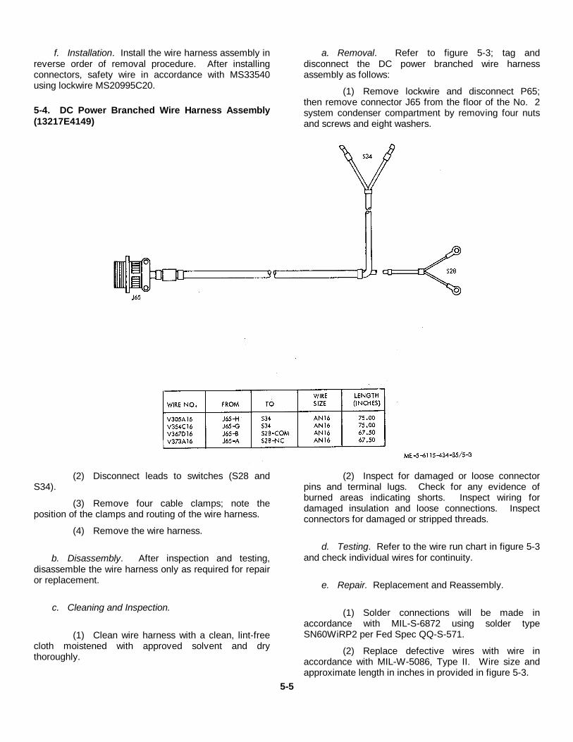
f. Installation. Install the wire harness assembly inreverse order of removal procedure. After installingconnectors, safety wire in accordance with MS33540using lockwire MS20995C20.
5-4. DC Power Branched Wire Harness Assembly(13217E4149)
a. Removal. Refer to figure 5-3; tag anddisconnect the DC power branched wire harnessassembly as follows:
(1) Remove lockwire and disconnect P65;then remove connector J65 from the floor of the No. 2system condenser compartment by removing four nutsand screws and eight washers.
(2) Disconnect leads to switches (S28 andS34).
(3) Remove four cable clamps; note theposition of the clamps and routing of the wire harness.
(4) Remove the wire harness.
b. Disassembly. After inspection and testing,disassemble the wire harness only as required for repairor replacement.
c. Cleaning and Inspection.
(1) Clean wire harness with a clean, lint-freecloth moistened with approved solvent and drythoroughly.
(2) Inspect for damaged or loose connectorpins and terminal lugs. Check for any evidence ofburned areas indicating shorts. Inspect wiring fordamaged insulation and loose connections. Inspectconnectors for damaged or stripped threads.
d. Testing. Refer to the wire run chart in figure 5-3and check individual wires for continuity.
e. Repair. Replacement and Reassembly.
(1) Solder connections will be made inaccordance with MIL-S-6872 using solder typeSN60WiRP2 per Fed Spec QQ-S-571.
(2) Replace defective wires with wire inaccordance with MIL-W-5086, Type II. Wire size andapproximate length in inches in provided in figure 5-3.
5-5

(3) If replacement of connector J65 isnecessary, remove potting compound and unsolderelectrical leads. Solder electrical leads toreplacement connector. Fill connector backshell withsilicone rubber sealing compound (501 RTV andCatalyst 501A, Dow Corning Corp., Midland, Michigan,or equivalent).
(4) If self-clinching cable straps are removedto facilitate repairs, install new cable straps at five inchintervals and all cable breakouts.
f. Installation. Install the wire harness assembly inreverse order of removal procedure. After installing
connectors J65 and P65, safety wire in accordance withMS33540 using lockwire MS20995C20.
a. Removal. Refer to figure 5-4; tag and removethe water system wire harness assembly by removinglockwire and disconnecting P41, P42 and PilI; thenremove connectors J41, J42, and J71 by removing fournuts and screws and eight washers from each.
b. Disassembly. After inspection and testing,disassemble the wire harness only as required for repairor replacement.
Figure 5-4. Water system wire harness assembly.
c. Cleaning and Inspection.
(1) Clean wire harness with a clean, lint-freecloth moistened with approved solvent and drythoroughly.
(2) Check for any evidence of burned areasindicating shorts. Inspect wiring for damaged insulationand loose connections. Inspect connectors for damagedor stripped threads and damaged or loose pins.
d. Testing. Refer to the wire run chart in figure 5-4and check individual wires for continuity.
e. Repair, Replacement and Reassembly.
(1) Solder connections will be made inaccordance with MIL-S-6872 using solder typeSN60WRP2 per Fed Spec QQ-S-571.
(2) Replace defective wires with wire inaccordance with MIL-W-5086, Type II. Wire size andapproximate length in inches is provided in figure 5-4.
(3) If replacement of connectors (J41, J42,J71) is necessary, remove potting compound andunsolder electrical leads. Solder electrical leads to
5-6
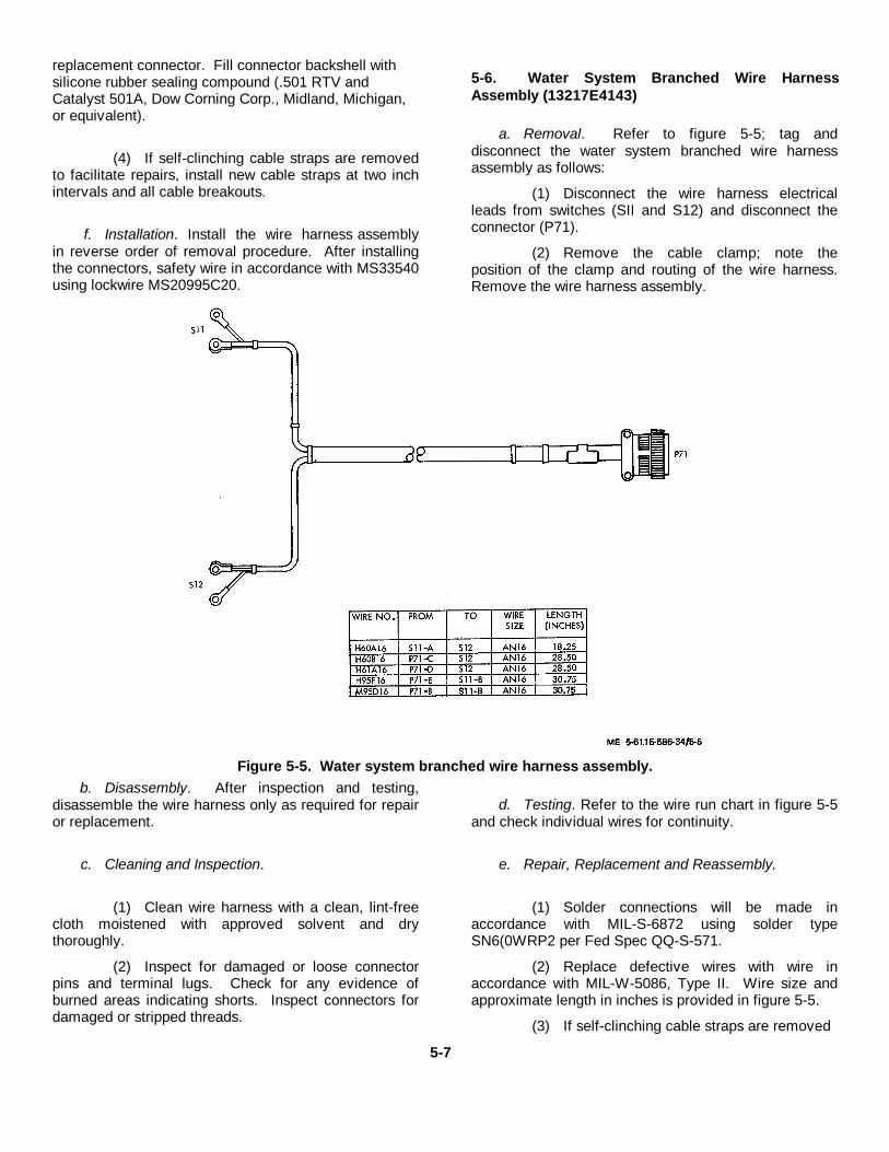
replacement connector. Fill connector backshell withsilicone rubber sealing compound (.501 RTV andCatalyst 501A, Dow Corning Corp., Midland, Michigan,or equivalent).
(4) If self-clinching cable straps are removedto facilitate repairs, install new cable straps at two inchintervals and all cable breakouts.
f. Installation. Install the wire harness assemblyin reverse order of removal procedure. After installingthe connectors, safety wire in accordance with MS33540using lockwire MS20995C20.
5-6. Water System Branched Wire HarnessAssembly (13217E4143)
a. Removal. Refer to figure 5-5; tag anddisconnect the water system branched wire harnessassembly as follows:
(1) Disconnect the wire harness electricalleads from switches (SII and S12) and disconnect theconnector (P71).
(2) Remove the cable clamp; note theposition of the clamp and routing of the wire harness.Remove the wire harness assembly.
Figure 5-5. Water system branched wire harness assembly.b. Disassembly. After inspection and testing,
disassemble the wire harness only as required for repairor replacement.
c. Cleaning and Inspection.
(1) Clean wire harness with a clean, lint-freecloth moistened with approved solvent and drythoroughly.
(2) Inspect for damaged or loose connectorpins and terminal lugs. Check for any evidence ofburned areas indicating shorts. Inspect connectors fordamaged or stripped threads.
d. Testing. Refer to the wire run chart in figure 5-5and check individual wires for continuity.
e. Repair, Replacement and Reassembly.
(1) Solder connections will be made inaccordance with MIL-S-6872 using solder typeSN6(0WRP2 per Fed Spec QQ-S-571.
(2) Replace defective wires with wire inaccordance with MIL-W-5086, Type II. Wire size andapproximate length in inches is provided in figure 5-5.
(3) If self-clinching cable straps are removed
5-7
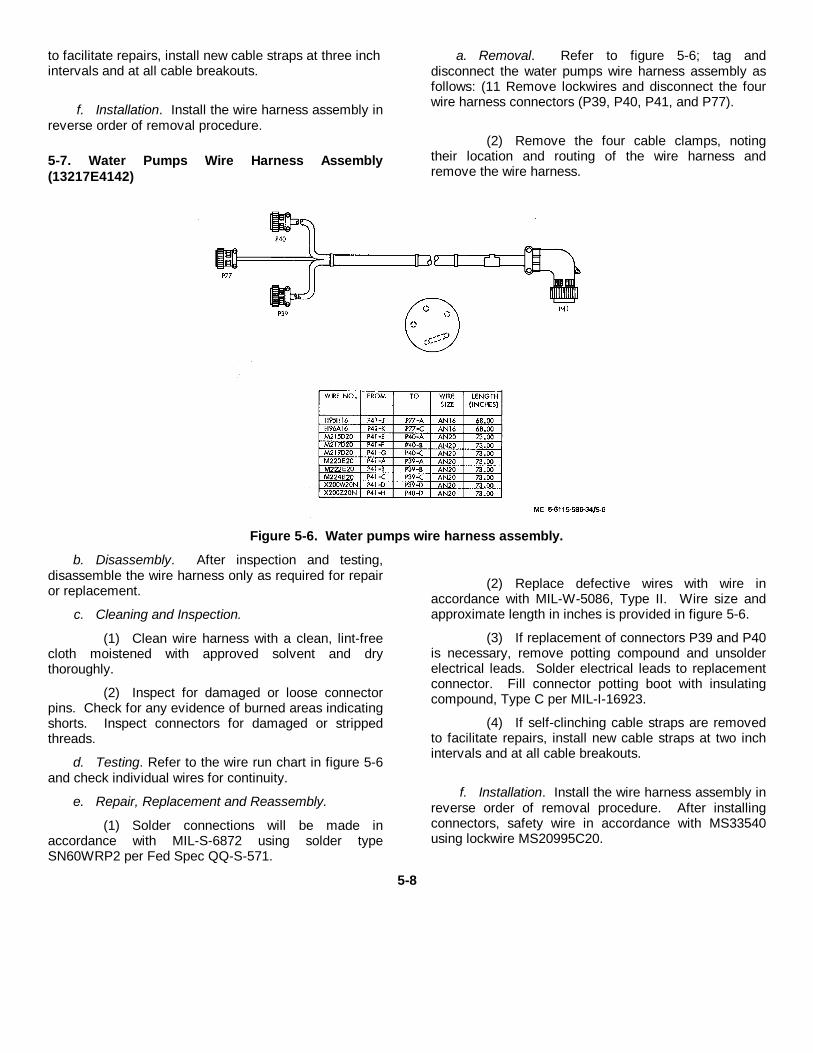
to facilitate repairs, install new cable straps at three inchintervals and at all cable breakouts.
f. Installation. Install the wire harness assembly inreverse order of removal procedure.
5-7. Water Pumps Wire Harness Assembly(13217E4142)
a. Removal. Refer to figure 5-6; tag anddisconnect the water pumps wire harness assembly asfollows: (11 Remove lockwires and disconnect the fourwire harness connectors (P39, P40, P41, and P77).
(2) Remove the four cable clamps, notingtheir location and routing of the wire harness andremove the wire harness.
Figure 5-6. Water pumps wire harness assembly.
b. Disassembly. After inspection and testing,disassemble the wire harness only as required for repairor replacement.
c. Cleaning and Inspection.
(1) Clean wire harness with a clean, lint-freecloth moistened with approved solvent and drythoroughly.
(2) Inspect for damaged or loose connectorpins. Check for any evidence of burned areas indicatingshorts. Inspect connectors for damaged or strippedthreads.
d. Testing. Refer to the wire run chart in figure 5-6and check individual wires for continuity.
e. Repair, Replacement and Reassembly.
(1) Solder connections will be made inaccordance with MIL-S-6872 using solder typeSN60WRP2 per Fed Spec QQ-S-571.
(2) Replace defective wires with wire inaccordance with MIL-W-5086, Type II. Wire size andapproximate length in inches is provided in figure 5-6.
(3) If replacement of connectors P39 and P40is necessary, remove potting compound and unsolderelectrical leads. Solder electrical leads to replacementconnector. Fill connector potting boot with insulatingcompound, Type C per MIL-I-16923.
(4) If self-clinching cable straps are removedto facilitate repairs, install new cable straps at two inchintervals and at all cable breakouts.
f. Installation. Install the wire harness assembly inreverse order of removal procedure. After installingconnectors, safety wire in accordance with MS33540using lockwire MS20995C20.
5-8
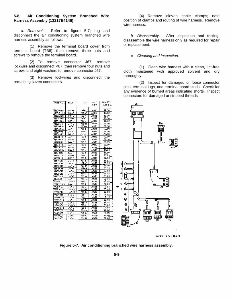
5-8. Air Conditioning System Branched WireHarness Assembly (13217E4146)
a. Removal. Refer to figure 5-7; tag anddisconnect the air conditioning system branched wireharness assembly as follows:
(1) Remove the terminal board cover fromterminal board (TB8); then remove three nuts andscrews to remove the terminal board.
(2) To remove connector J67, removelockwire and disconnect P67, then remove four nuts andscrews and eight washers to remove connector J67.
(3) Remove lockwires and disconnect theremaining seven connectors.
(4) Remove eleven cable clamps; noteposition of clamps and routing of wire harness. Removewire harness.
b. Disassembly. After inspection and testing,disassemble the wire harness only as required for repairor replacement.
c. Cleaning and Inspection.
(1) Clean wire harness with a clean, lint-freecloth moistened with approved solvent and drythoroughly.
(2) Inspect for damaged or loose connectorpins, terminal lugs, and terminal board studs. Check forany evidence of burned areas indicating shorts. Inspectconnectors for damaged or stripped threads.
Figure 5-7. Air conditioning branched wire harness assembly.
5-9
d. Testing. Refer to the wire run chart in figure 5-7and check individual wires for continuity.
e. Repair, Replacement and Reassembly.
(1) Solder connections will be made inaccordance with MIL-S-6872 using solder typeSN60OWRP2 per Fed Spec QQ-S-571.
(2) Replace defective wires with wire inaccordance with MIL-W-5086, Type II. Wire size andapproximate length in inches is provided in figure 5-7.
(3) If self-clinching cable straps are removedto facilitate repairs, install new cable straps at three inchintervals and at all cable breakouts.
f. Installation. Install the wire harnessassembly in reverse order of removal procedure. Afterinstalling connectors. Safety wire in accordance withMS33540 using lockwire MS20995C20.
5-9. Air Conditioning System 'Wire HarnessAssembly (13217E4145)
a. Removal. Refer to figure 5-8; tag anddisconnect the air conditioning system wire harnessassembly as follows: (1) Remove the terminal boardcover from terminal board (TB91. Remove three nuts,screws, and washers and remove the terminal board.
5-10
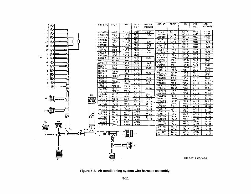
Figure 5-8. Air conditioning system wire harness assembly.
5-11
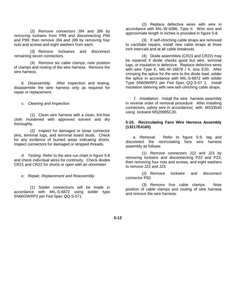
(2) Remove connectors J94 and J99 byremoving lockwire from P99 and disconnecting P94and P99; then remove J94 and J99 by removing fournuts and screws and eight washers from each.
(3) Remove lockwires and disconnectremaining seven connectors.
(4) Remove six cable clamps; note positionof clamps and routing of the wire harness. Remove thewire harness.
b. Disassembly. After inspection and testing,disassemble the wire harness only as required forrepair or replacement.
c. Cleaning and Inspection.
(1) Clean wire harness with a clean, lint-freecloth moistened with approved solvent and drythoroughly.
(2) Inspect for damaged or loose connectorpins, terminal lugs, and terminal board studs. Checkfor any evidence of burned areas indicating shorts.Inspect connectors for damaged or stripped threads.
d. Testing. Refer to the wire run chart in figure 5-8and check individual wires for continuity. Check diodesCR21 and CR22 for shorts or open with an ohmmeter.
e. Repair, Replacement and Reassembly.
(1) Solder connections will be made inaccordance with MIL-S-6872 using solder typeSN60OWRP2 per Fed Spec QQ-S-571.
(2) Replace defective wires with wire inaccordance with MIL-W-5086, Type II. Wire size andapproximate length in inches is provided in figure 5-8.
(3) If self-clinching cable straps are removedto vacilitate repairs, install new cable straps at threeinch intervals and at all cable breakouts.
(4) Diode assemblies (CR21 and CR22) maybe repaired if diode checks good but wire, terminallugs, or insulation is defective. Replace defective wireswith wire Type E, MIL-W-16878 / 4, size E20. Aftercrimping the splice for the wire to the diode lead, solderthe splice in accordance with MIL-S-6872 with solderType SN60WRP2 per Fed Spec QQ-S-57 1. Installinsulation sleeving with new self-clinching cable straps.
f. Installation. Install the wire harness assemblyin reverse order of removal procedure. After installingconnectors, safety wire in accordance( with MS33540using lockwire MS20995C20.
5-10. Recirculating Fans Wire Harness Assembly(13217E4165)
a. Removal. Refer to figure 5-9; tag anddisconnect the recirculating fans wire harnessassembly as follows:
(1) Remove connectors J22 and J23 byremoving lockwire and disconnecting P22 and P23;then removing four nuts and screws, and eight washersto remove J22 and J23.
(2) Remove lockwire and disconnectconnector P92.
(3) Remove five cable clamps. Noteposition of cable clamps and routing of wire harnessand remove the wire harness.
5-12
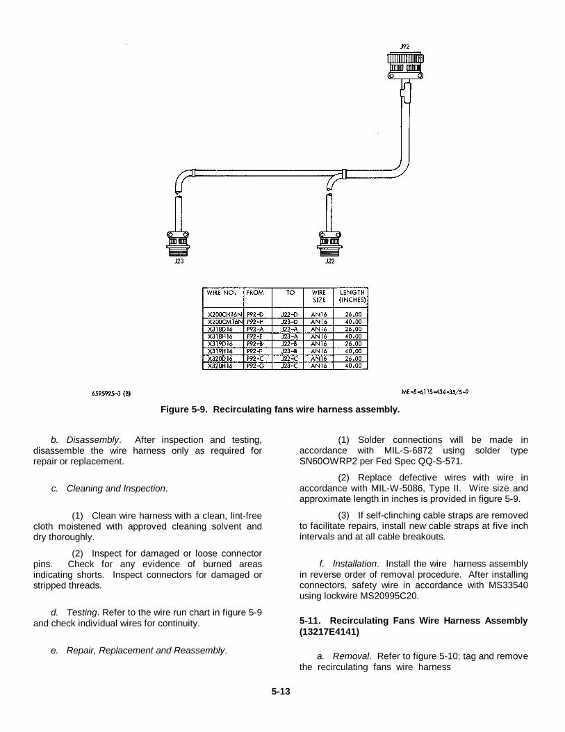
Figure 5-9. Recirculating fans wire harness assembly.
b. Disassembly. After inspection and testing,disassemble the wire harness only as required forrepair or replacement.
c. Cleaning and Inspection.
(1) Clean wire harness with a clean, lint-freecloth moistened with approved cleaning solvent anddry thoroughly.
(2) Inspect for damaged or loose connectorpins. Check for any evidence of burned areasindicating shorts. Inspect connectors for damaged orstripped threads.
d. Testing. Refer to the wire run chart in figure 5-9and check individual wires for continuity.
e. Repair, Replacement and Reassembly.
(1) Solder connections will be made inaccordance with MIL-S-6872 using solder typeSN60OWRP2 per Fed Spec QQ-S-571.
(2) Replace defective wires with wire inaccordance with MIL-W-5086, Type II. Wire size andapproximate length in inches is provided in figure 5-9.
(3) If self-clinching cable straps are removedto facilitate repairs, install new cable straps at five inchintervals and at all cable breakouts.
f. Installation. Install the wire harness assemblyin reverse order of removal procedure. After installingconnectors, safety wire in accordance with MS33540using lockwire MS20995C20.
5-11. Recirculating Fans Wire Harness Assembly(13217E4141)
a. Removal. Refer to figure 5-10; tag and removethe recirculating fans wire harness
5-13
assembly by removing lockwire and mating connectorsand remove four nuts, four screws and eight washersfrom each connector (J20, J21 and J92).
Remove lockwire, disconnect connector P34, andremove the wire harness assembly.
b. Disassembly. After inspection and testing,disassemble the wire harness only as required for repairor replacement.
c. Cleaning and Inspection.
(1) Clean wire harness with a clean, lint-freecloth moistened with approved solvent and drythoroughly.
(2) Inspect for damaged or loose connectorpins. Check for any evidence of burned areas indicatingshorts. Inspect connectors for damaged or strippedthreads.
d. Testing. Refer to the wire run chart in figure 5-10 and check individual wires for continuity.
e. Repair, Replacement and Reassembly.
(1) Solder connections will be made inaccordance with MIL-S-6872 using solder TypeSN6OWRP2 per Fed Spec QQ-S-571.
(2) Replace defective wires with wire inaccordance with MIL-W-5086, Type II. Wire size andapproximate length in inches is provided in figure 5-10.
(3) If self-clinching cable straps are removedto facilitate repairs, install new cable straps at two inchintervals and at all cable breakouts.
f. Installation. Install the wire harness assemblyin reverse order of removal procedure.
After installing connectors, safety wire to the attachinghardware in accordance with MS33540 using lockwireMS20995C20.
5-12. Recirculating Fans Wire Harness Assembly(13217E4148)
a. Removal. Refer to figure 5-11; tag anddisconnect the recirculating fans wire harness asfollows: Figure 5-10. Recirculating fans wire harnessassembly.
5-14
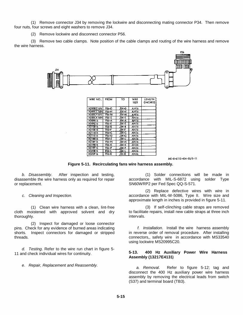
(1) Remove connector J34 by removing the lockwire and disconnecting mating connector P34. Then removefour nuts, four screws and eight washers to remove J34.
(2) Remove lockwire and disconnect connector P56.
(3) Remove two cable clamps. Note position of the cable clamps and routing of the wire harness and removethe wire harness.
Figure 5-11. Recirculating fans wire harness assembly.
b. Disassembly. After inspection and testing,disassemble the wire harness only as required for repairor replacement.
c. Cleaning and Inspection.
(1) Clean wire harness with a clean, lint-freecloth moistened with approved solvent and drythoroughly.
(2) Inspect for damaged or loose connectorpins. Check for any evidence of burned areas indicatingshorts. Inspect connectors for damaged or strippedthreads.
d. Testing. Refer to the wire run chart in figure 5-11 and check individual wires for continuity.
e. Repair, Replacement and Reassembly.
(1) Solder connections will be made inaccordance with MIL-S-6872 using solder TypeSN60WRP2 per Fed Spec QQ-S-571.
(2) Replace defective wires with wire inaccordance with MIL-W-5086, Type II. Wire size andapproximate length in inches is provided in figure 5-11.
(3) If self-clinching cable straps are removedto facilitate repairs, install new cable straps at three inchintervals.
f. Installation. Install the wire harness assemblyin reverse order of removal procedure. After installingconnectors,, safety wire in accordance with MS33540using lockwire MS20995C20.
5-13. 400 Hz Auxiliary Power Wire HarnessAssembly (13217E4131)
a. Removal. Refer to figure 5-12; tag anddisconnect the 400 Hz auxiliary power wire harnessassembly by removing the electrical leads from switch(S37) and terminal board (TB3).
5-15
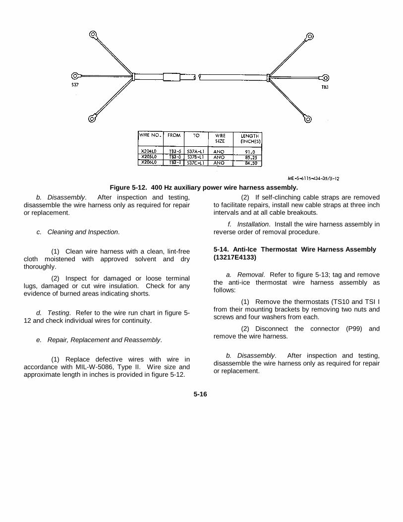
Figure 5-12. 400 Hz auxiliary power wire harness assembly.b. Disassembly. After inspection and testing,
disassemble the wire harness only as required for repairor replacement.
c. Cleaning and Inspection.
(1) Clean wire harness with a clean, lint-freecloth moistened with approved solvent and drythoroughly.
(2) Inspect for damaged or loose terminallugs, damaged or cut wire insulation. Check for anyevidence of burned areas indicating shorts.
d. Testing. Refer to the wire run chart in figure 5-12 and check individual wires for continuity.
e. Repair, Replacement and Reassembly.
(1) Replace defective wires with wire inaccordance with MIL-W-5086, Type II. Wire size andapproximate length in inches is provided in figure 5-12.
(2) If self-clinching cable straps are removedto facilitate repairs, install new cable straps at three inchintervals and at all cable breakouts.
f. Installation. Install the wire harness assembly inreverse order of removal procedure.
5-14. Anti-Ice Thermostat Wire Harness Assembly(13217E4133)
a. Removal. Refer to figure 5-13; tag and removethe anti-ice thermostat wire harness assembly asfollows:
(1) Remove the thermostats (TS10 and TSI Ifrom their mounting brackets by removing two nuts andscrews and four washers from each.
(2) Disconnect the connector (P99) andremove the wire harness.
b. Disassembly. After inspection and testing,disassemble the wire harness only as required for repairor replacement.
5-16
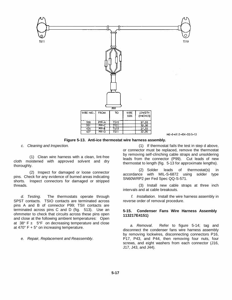
Figure 5-13. Anti-ice thermostat wire harness assembly.c. Cleaning and Inspection.
(1) Clean wire harness with a clean, lint-freecloth moistened with approved solvent and drythoroughly.
(2) Inspect for damaged or loose connectorpins. Check for any evidence of burned areas indicatingshorts. Inspect connectors for damaged or strippedthreads.
d. Testing. The thermostats operate throughSPST contacts. TSIO contacts are terminated acrosspins A and B of connector P99; TSII contacts areterminated across pins C and D (fig. 513). Use anohmmeter to check that circuits across these pins openand close at the following ambient temperatures: Openat 38° F ± 5°F on decreasing temperature and closeat 470° F + 5° on increasing temperature.
e. Repair, Replacement and Reassembly.
(1) If thermostat fails the test in step d above,or connector must be replaced, remove the thermostatby removing self-clinching cable straps and unsolderingleads from the connector (P99). Cut leads of newthermostat to length (fig. 5-13 for approximate lengths).
(2) Solder leads of thermostat(s) inaccordance with MIL-S-6872 using solder typeSN60WRP2 per Fed Spec QQ-S-571.
(3) Install new cable straps at three inchintervals and at cable breakouts.
f. Installation. Install the wire harness assembly inreverse order of removal procedure.
5-15. Condenser Fans Wire Harness Assembly113217E4151)
a. Removal. Refer to figure 5-14; tag anddisconnect the condenser fans wire harness assemblyby removing lockwires, disconnecting connectors P16,P17, P43, and P44, then removing four nuts, fourscrews, and eight washers from each connector (J16,J17, J43, and J44).
5-17
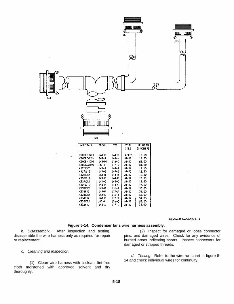
Figure 5-14. Condenser fans wire harness assembly.b. Disassembly. After inspection and testing,
disassemble the wire harness only as required for repairor replacement.
c. Cleaning and Inspection.
(1) Clean wire harness with a clean, lint-freecloth moistened with approved solvent and drythoroughly.
(2) Inspect for damaged or loose connectorpins, and damaged wires. Check for any evidence ofburned areas indicating shorts. Inspect connectors fordamaged or stripped threads.
d. Testing. Refer to the wire run chart in figure 5-14 and check individual wires for continuity.
5-18
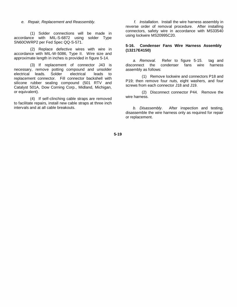
e. Repair, Replacement and Reassembly.
(1) Solder connections will be made inaccordance with MIL-S-6872 using solder TypeSN60OWRP2 per Fed Spec QQ-S-571.
(2) Replace defective wires with wire inaccordance with MIL-W-5086, Type II. Wire size andapproximate length in inches is provided in figure 5-14.
(3) If replacement of connector J43 isnecessary, remove potting compound and unsolderelectrical leads. Solder electrical leads toreplacement connector. Fill connector backshell withsilicone rubber sealing compound (501 RTV andCatalyst 501A, Dow Corning Corp., Midland, Michigan,or equivalent).
(4) If self-clinching cable straps are removedto facilitate repairs, install new cable straps at three inchintervals and at all cable breakouts.
f. Installation. Install the wire harness assembly inreverse order of removal procedure. After installingconnectors, safety wire in accordance with MS33540using lockwire MS20995C20.
5-16. Condenser Fans Wire Harness Assembly(13217E4150)
a. Removal. Refer to figure 5-15. tag anddisconnect the condenser fans wire harnessassembly as follows:
(1) Remove lockwire and connectors P18 andP19; then remove four nuts, eight washers, and fourscrews from each connector J18 and J19.
(2) Disconnect connector P44. Remove thewire harness.
b. Disassembly. After inspection and testing,disassemble the wire harness only as required for repairor replacement.
5-19
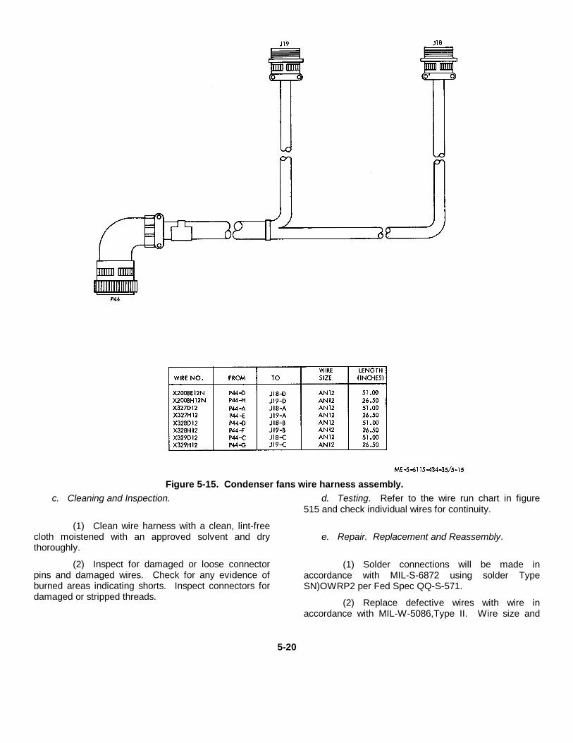
Figure 5-15. Condenser fans wire harness assembly.c. Cleaning and Inspection.
(1) Clean wire harness with a clean, lint-freecloth moistened with an approved solvent and drythoroughly.
(2) Inspect for damaged or loose connectorpins and damaged wires. Check for any evidence ofburned areas indicating shorts. Inspect connectors fordamaged or stripped threads.
d. Testing. Refer to the wire run chart in figure515 and check individual wires for continuity.
e. Repair. Replacement and Reassembly.
(1) Solder connections will be made inaccordance with MIL-S-6872 using solder TypeSN)OWRP2 per Fed Spec QQ-S-571.
(2) Replace defective wires with wire inaccordance with MIL-W-5086,Type II. Wire size and
5-20
approximate length in inches is provided in figure 5-15.
(3) If self-clinching cable straps are removedto facilitate repairs, install new cable straps at three inchintervals and at all cable breakouts.
f. Installation. Install the wire harness assembly inreverse order of removal procedure. After installingconnectors, safety wire in accordance with MS35540using lockwire MS20995C20.
5-17. Remote Power Output Wire HarnessAssembly (13217E4156)
a. Removal. Refer to figure 5-16; tag anddisconnect the remote power output wire harnessassembly as follows:
(1) Remove lockwire and connectors PII,P74, and P75; then remove nuts, washers and screwsfrom connectors J 1, J74, and J75. Remove wire leadconnections to capacitors (C19, C20, C21, C22, C23,C24) near J74 and J75.
(2) Remove wire lead connections to terminalboards (TB4, TB7).
(3) Disconnect connectors P70 and P76.Remove the wire harness.
5-21
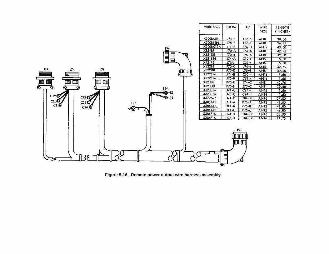
Figure 5-16. Remote power output wire harness assembly.
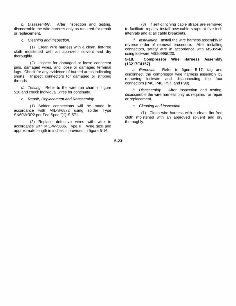
b. Disassembly. After inspection and testing,disassemble the wire harness only as required for repairor replacement.
c. Cleaning and Inspection.
(1) Clean wire harness with a clean, lint-freecloth moistened with an approved solvent and drythoroughly.
(2) Inspect for damaged or loose connectorpins, damaged wires, and loose or damaged terminallugs. Check for any evidence of burned areas indicatingshorts. Inspect connectors for damaged or strippedthreads.
d. Testing. Refer to the wire run chart in figure516 and check individual wires for continuity.
e. Repair, Replacement and Reassembly.
(1) Solder connections will be made inaccordance with MIL-S-6872 using solder TypeSN60WRP2 per Fed Spec QQ-S-571.
(2) Replace defective wires with wire inaccordance with MIL-W-5086, Type II. Wire size andapproximate length in inches is provided in figure 5-16.
(3) If self-clinching cable straps are removedto facilitate repairs, install new cable straps at five inchintervals and at all cable breakouts.
f. Installation. Install the wire harness assembly inreverse order of removal procedure. After installingconnectors, safety wire in accordance with MS35540using lockwire MS20995C20.5-18. Compressor Wire Harness Assembly(13217E4157)
a. Removal. Refer to figure 5-17; tag anddisconnect the compressor wire harness assembly byremoving lockwire and disconnecting the fourconnectors (P46, P48, P97, and P98).
b. Disassembly. After inspection and testing,disassemble the wire harness only as required for repairor replacement.
c. Cleaning and Inspection.
(1) Clean wire harness with a clean, lint-freecloth moistened with an approved solvent and drythoroughly.
5-23
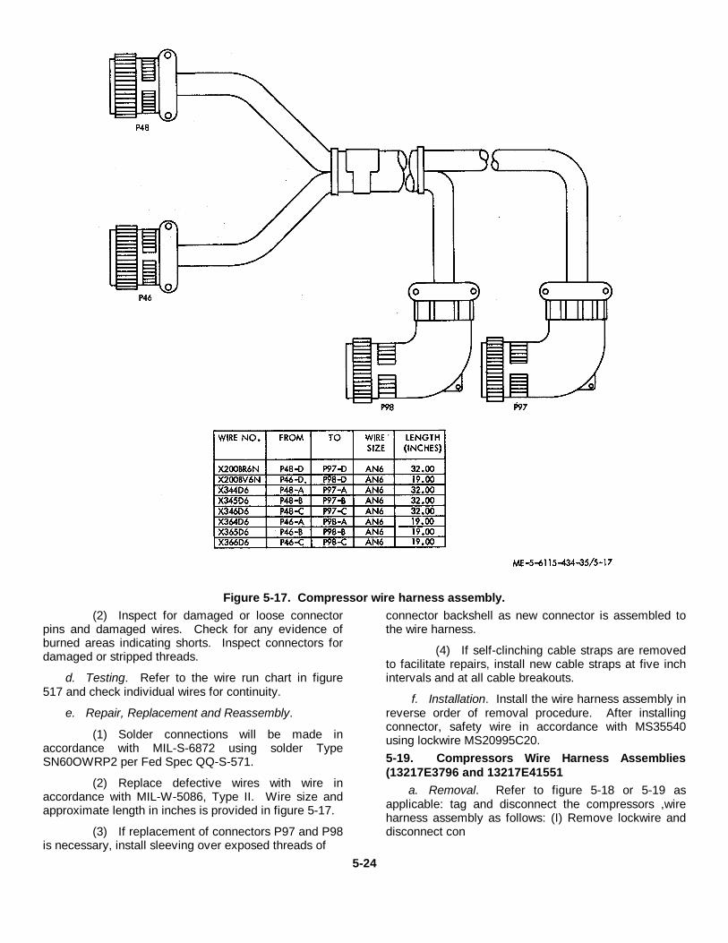
Figure 5-17. Compressor wire harness assembly.(2) Inspect for damaged or loose connector
pins and damaged wires. Check for any evidence ofburned areas indicating shorts. Inspect connectors fordamaged or stripped threads.
d. Testing. Refer to the wire run chart in figure517 and check individual wires for continuity.
e. Repair, Replacement and Reassembly.
(1) Solder connections will be made inaccordance with MIL-S-6872 using solder TypeSN60OWRP2 per Fed Spec QQ-S-571.
(2) Replace defective wires with wire inaccordance with MIL-W-5086, Type II. Wire size andapproximate length in inches is provided in figure 5-17.
(3) If replacement of connectors P97 and P98is necessary, install sleeving over exposed threads of
connector backshell as new connector is assembled tothe wire harness.
(4) If self-clinching cable straps are removedto facilitate repairs, install new cable straps at five inchintervals and at all cable breakouts.
f. Installation. Install the wire harness assembly inreverse order of removal procedure. After installingconnector, safety wire in accordance with MS35540using lockwire MS20995C20.5-19. Compressors Wire Harness Assemblies(13217E3796 and 13217E41551
a. Removal. Refer to figure 5-18 or 5-19 asapplicable: tag and disconnect the compressors ,wireharness assembly as follows: (I) Remove lockwire anddisconnect con
5-24
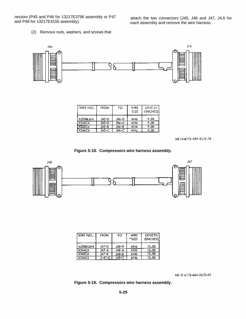
nectors (P45 and P46 for 13217E3796 assembly or P47and P48 for 13217E4155 assembly).
(2) Remove nuts, washers, and screws that
attach the two connectors (J45, J46 and J47, J4,lt foreach assembly and remove the wire harness.
Figure 5-18. Compressors wire harness assembly.
Figure 5-19. Compressors wire harness assembly.
5-25
b. Disassembly. After inspection and testing,disassemble the wire harnesses only as required forrepair or replacement.
c. Cleaning and Inspection.
(1) Clean wire harness with a clean. lint-freecloth moistened with an approved solvent and drythoroughly.
(2) Inspect for damaged or loose connectorpins. damaged wires. and loose or damaged terminallugs. Check for any evidence of burned areas indicatingshorts. Inspect connectors for damaged or strippedthreads.
d. Testing. Refer to the wire run chart in figure518 or 5-19 as applicable and check individual wires forcontinuity.
e. Repair, Replacement and Reassembly.
(1) Solder connections will be made inaccordance with MIL-S-6872 using solder TypeSN60OWRP2 per Fed Spec QQ-S-571.
(2) Replace defective wires with wire inaccordance with MIL-W-5086, Type II. Wire size
and approximate length in inches is provided in figure 5-18 and 5-19.
(3) If replacement of connector J45 or J47 isnecessary. remove potting compound and unsolderelectrical leads. Fill connector backshell with siliconerubber sealing compound (510 RTV and Catalyst 501A.Dow Corning Corp., Midland, Michigan, or equivalent) atreassembly.
(4) If self-clinching cable straps are removedto facilitate repairs, install new cable straps at five inchintervals and at all cable breakouts.
f. Installation. Install the wire harness assembliesin reverse order of removal procedure. After installingconnectors. safety wire in accordance with MS35540using lockwire MS20995C20.
5-20. Compressor and Exhaust Fans Wire HarnessAssembly 113217E4152)
a. Removal. Refer to figure 5-20; tag anddisconnect the compressor and exhaust fans wireharness assembly as follows.
5-26
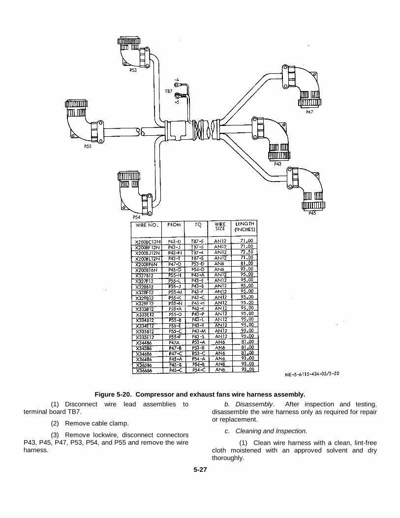
Figure 5-20. Compressor and exhaust fans wire harness assembly.(1) Disconnect wire lead assemblies to
terminal board TB7.
(2) Remove cable clamp.
(3) Remove lockwire, disconnect connectorsP43, P45, P47, P53, P54, and P55 and remove the wireharness.
b. Disassembly. After inspection and testing,disassemble the wire harness only as required for repairor replacement.
c. Cleaning and Inspection.
(1) Clean wire harness with a clean, lint-freecloth moistened with an approved solvent and drythoroughly.
5-27
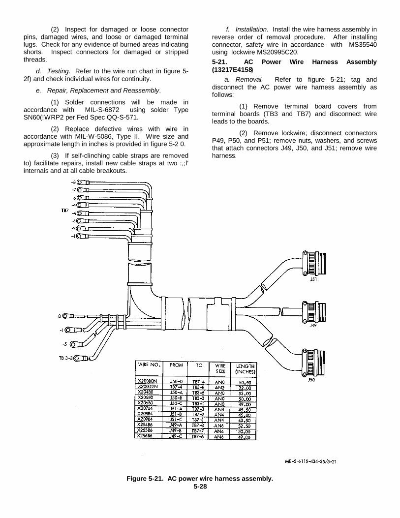
(2) Inspect for damaged or loose connectorpins, damaged wires, and loose or damaged terminallugs. Check for any evidence of burned areas indicatingshorts. Inspect connectors for damaged or strippedthreads.
d. Testing. Refer to the wire run chart in figure 5-2f) and check individual wires for continuity.
e. Repair, Replacement and Reassembly.
(1) Solder connections will be made inaccordance with MIL-S-6872 using solder TypeSN60(!WRP2 per Fed Spec QQ-S-571.
(2) Replace defective wires with wire inaccordance with MIL-W-5086, Type II. Wire size andapproximate length in inches is provided in figure 5-2 0.
(3) If self-clinching cable straps are removedto) facilitate repairs, install new cable straps at two :,;l'internals and at all cable breakouts.
f. Installation. Install the wire harness assembly inreverse order of removal procedure. After installingconnector, safety wire in accordance with MS35540using lockwire MS20995C20.5-21. AC Power Wire Harness Assembly(13217E4158)
a. Removal. Refer to figure 5-21; tag anddisconnect the AC power wire harness assembly asfollows:
(1} Remove terminal board covers fromterminal boards (TB3 and TB7) and disconnect wireleads to the boards.
(2) Remove lockwire; disconnect connectorsP49, P50, and P51; remove nuts, washers, and screwsthat attach connectors J49, J50, and J51; remove wireharness.
Figure 5-21. AC power wire harness assembly.5-28
b. Disassembly. After inspection and testing,disassemble the wire harness only as required for repairor replacement.
c. Cleaning and Inspection.
(1) Clean wire harness with a clean, lint-freecloth moistened with an approved solvent and drythoroughly.
(2) Inspect for damaged or loose connectorpins, damaged wires, and loose or damaged terminallugs. Check for any evidence of burned areas indicatingshorts. Inspect connectors for damaged or strippedthreads.
d. Testing. Refer to the wire run chart in figure 5-21 and check individual wires for continuity.
e. Repair, Replacement and Reassembly.
(1) Solder connections will be made inaccordance with MIL-S-6872 using solder TypeSN60WRP2 per Fed Spec QQ-S-571.
(2) Replace defective wires with wire inaccordance with MIL-W-5086, Type II. Wire size andapproximate length in inches is provided in figure 5-21.
(3) If replacement of connector J50 isnecessary, remove potting compound and unsolder
electrical leads. Fill connector backshell with siliconerubber sealing compound (501 RTV and Catalyst 501A,Dow Corning Corp., Midland, Michigan, or equivalent) atreassembly.
(4) If self-clinching cable straps are removedto facilitate repairs, install new cable straps at three inchintervals and at all cable breakouts.
f. Installation. Install the wire harness assembly inreverse order of removal procedure. After installingconnector, safety wire in accordance with MS35540using lockwire MS20995C20.5-22. Temperature Sensors Wire Harness Assembly(13217E4159)
a. Removal. Refer to figure 5-22; tag anddisconnect the temperature sensors wire harnessassembly as follows.
(1) Remove lockwire; disconnect connectorP86; then remove nuts, lockwashers, and screws thatattach connector J86.
(2) Disconnect wire leads at temperaturesensors (RT5, RT6, RT7, and RT8).
(3) Remove seven loop-type cable clampsand remove the wire harness.
5-29
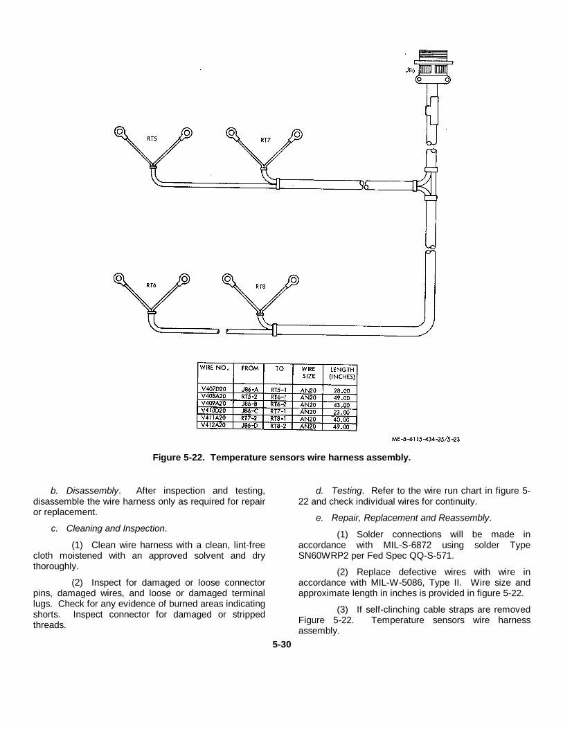
Figure 5-22. Temperature sensors wire harness assembly.
b. Disassembly. After inspection and testing,disassemble the wire harness only as required for repairor replacement.
c. Cleaning and Inspection.
(1) Clean wire harness with a clean, lint-freecloth moistened with an approved solvent and drythoroughly.
(2) Inspect for damaged or loose connectorpins, damaged wires, and loose or damaged terminallugs. Check for any evidence of burned areas indicatingshorts. Inspect connector for damaged or strippedthreads.
d. Testing. Refer to the wire run chart in figure 5-22 and check individual wires for continuity.
e. Repair, Replacement and Reassembly.
(1) Solder connections will be made inaccordance with MIL-S-6872 using solder TypeSN60WRP2 per Fed Spec QQ-S-571.
(2) Replace defective wires with wire inaccordance with MIL-W-5086, Type II. Wire size andapproximate length in inches is provided in figure 5-22.
(3) If self-clinching cable straps are removedFigure 5-22. Temperature sensors wire harnessassembly.
5-30

to facilitate repairs, install new cable straps at five inchintervals and at all cable breakouts.
f. Installation. Install the wire harness assembly inreverse order of removal procedure. After installingconnector, safety wire in accordance with MS35540using lockwire MS20995C20.
5-23. Temperature Sensors Wire HarnessAssembly (13217E4160)
a. Removal. Refer to figure 5-23; tag and
disconnect the temperature sensors wire harnessassembly as follows:
(1) Remove lockwires and disconnectconnectors P85 and P93; then remove nuts, washersand screws that attach connectors J85 and J93.
(2) Disconnect wire leads to temperaturesensors (RT1, RT2, RT3, and RT4). Remove sensorsfrom mounts by removing nuts, washers and screws.
(3) Remove seven loop-type cable clampsand remove wire harness.
5-31
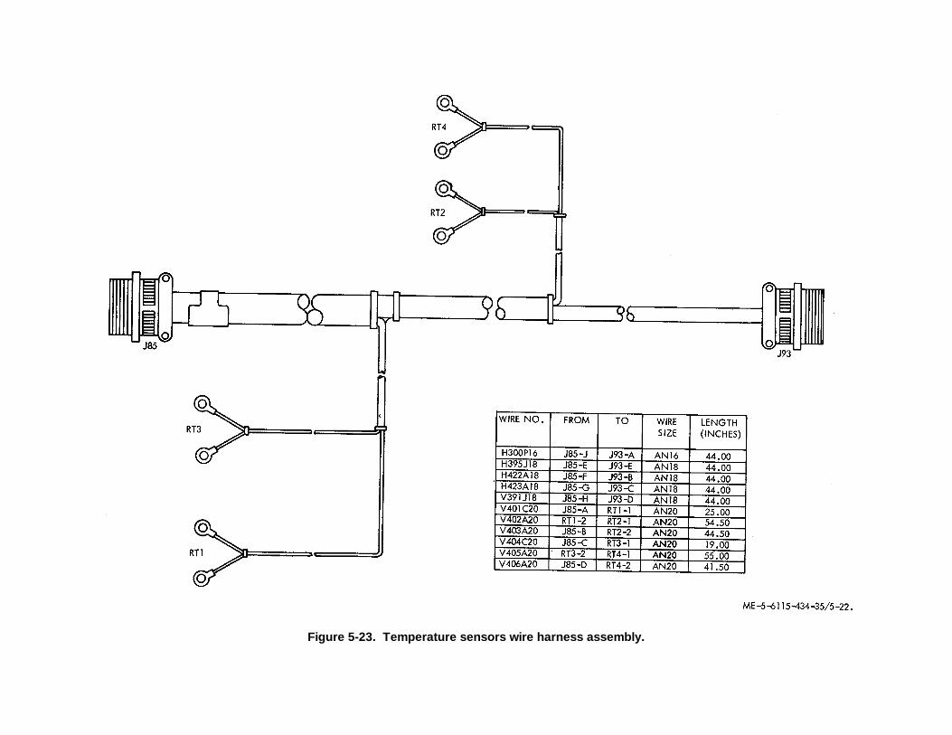
Figure 5-23. Temperature sensors wire harness assembly.
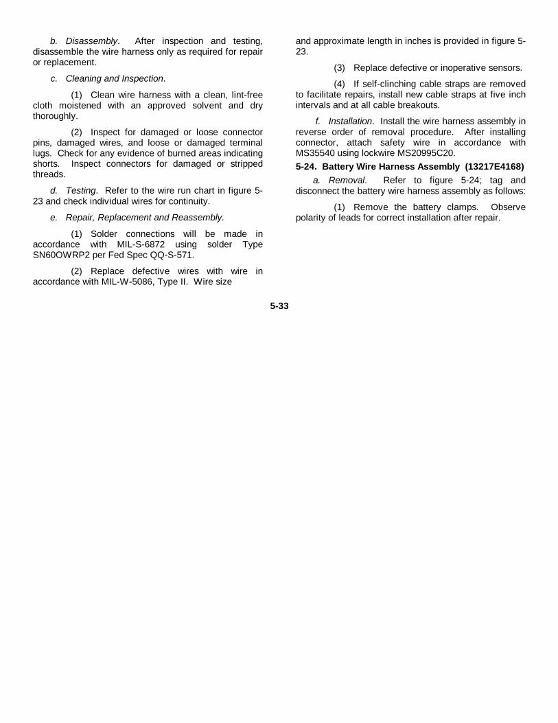
b. Disassembly. After inspection and testing,disassemble the wire harness only as required for repairor replacement.
c. Cleaning and Inspection.
(1) Clean wire harness with a clean, lint-freecloth moistened with an approved solvent and drythoroughly.
(2) Inspect for damaged or loose connectorpins, damaged wires, and loose or damaged terminallugs. Check for any evidence of burned areas indicatingshorts. Inspect connectors for damaged or strippedthreads.
d. Testing. Refer to the wire run chart in figure 5-23 and check individual wires for continuity.
e. Repair, Replacement and Reassembly.
(1) Solder connections will be made inaccordance with MIL-S-6872 using solder TypeSN60OWRP2 per Fed Spec QQ-S-571.
(2) Replace defective wires with wire inaccordance with MIL-W-5086, Type II. Wire size
and approximate length in inches is provided in figure 5-23.
(3) Replace defective or inoperative sensors.
(4) If self-clinching cable straps are removedto facilitate repairs, install new cable straps at five inchintervals and at all cable breakouts.
f. Installation. Install the wire harness assembly inreverse order of removal procedure. After installingconnector, attach safety wire in accordance withMS35540 using lockwire MS20995C20.5-24. Battery Wire Harness Assembly (13217E4168)
a. Removal. Refer to figure 5-24; tag anddisconnect the battery wire harness assembly as follows:
(1) Remove the battery clamps. Observepolarity of leads for correct installation after repair.
5-33
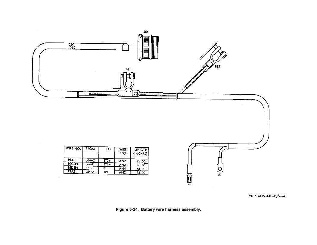
Figure 5-24. Battery wire harness assembly.
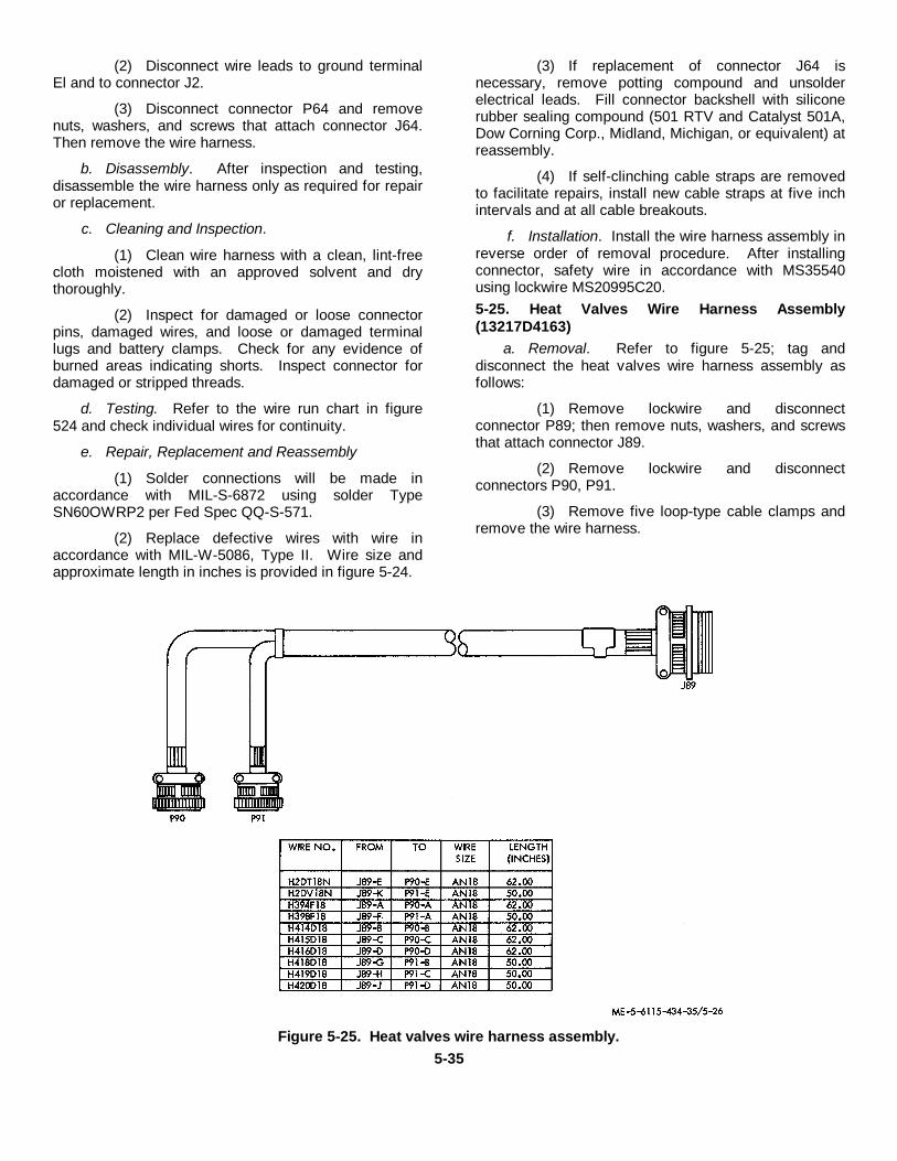
(2) Disconnect wire leads to ground terminalEl and to connector J2.
(3) Disconnect connector P64 and removenuts, washers, and screws that attach connector J64.Then remove the wire harness.
b. Disassembly. After inspection and testing,disassemble the wire harness only as required for repairor replacement.
c. Cleaning and Inspection.
(1) Clean wire harness with a clean, lint-freecloth moistened with an approved solvent and drythoroughly.
(2) Inspect for damaged or loose connectorpins, damaged wires, and loose or damaged terminallugs and battery clamps. Check for any evidence ofburned areas indicating shorts. Inspect connector fordamaged or stripped threads.
d. Testing. Refer to the wire run chart in figure524 and check individual wires for continuity.
e. Repair, Replacement and Reassembly
(1) Solder connections will be made inaccordance with MIL-S-6872 using solder TypeSN60OWRP2 per Fed Spec QQ-S-571.
(2) Replace defective wires with wire inaccordance with MIL-W-5086, Type II. Wire size andapproximate length in inches is provided in figure 5-24.
(3) If replacement of connector J64 isnecessary, remove potting compound and unsolderelectrical leads. Fill connector backshell with siliconerubber sealing compound (501 RTV and Catalyst 501A,Dow Corning Corp., Midland, Michigan, or equivalent) atreassembly.
(4) If self-clinching cable straps are removedto facilitate repairs, install new cable straps at five inchintervals and at all cable breakouts.
f. Installation. Install the wire harness assembly inreverse order of removal procedure. After installingconnector, safety wire in accordance with MS35540using lockwire MS20995C20.5-25. Heat Valves Wire Harness Assembly(13217D4163)
a. Removal. Refer to figure 5-25; tag anddisconnect the heat valves wire harness assembly asfollows:
(1) Remove lockwire and disconnectconnector P89; then remove nuts, washers, and screwsthat attach connector J89.
(2) Remove lockwire and disconnectconnectors P90, P91.
(3) Remove five loop-type cable clamps andremove the wire harness.
Figure 5-25. Heat valves wire harness assembly.5-35
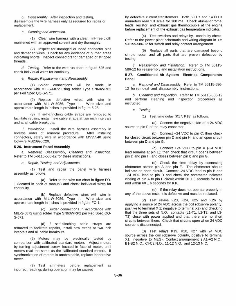
b. Disassembly. After inspection and testing,disassemble the wire harness only as required for repair orreplacement.
c. Cleaning and Inspection.
(1) Clean wire harness with a clean, lint-free clothmoistened with an approved solvent and dry thoroughly.
(2) Inspect for damaged or loose connector pinsand damaged wires. Check for any evidence of burned areasindicating shorts. Inspect connectors for damaged or strippedthreads.
d. Testing. Refer to the wire run chart in figure 525 andcheck individual wires for continuity.
e. Repair, Replacement and Reassembly.
(1) Solder connections will be made inaccordance with MIL-S-6872 using solder Type SN60WRP2per Fed Spec QQ-S-571.
(2) Replace defective wires with wire inaccordance with MIL-W-5086, Type II. Wire size andapproximate length in inches is provided in figure 5-25.
(3) If self-clinching cable straps are removed tofacilitate repairs, install new cable straps at two inch intervalsand at all cable breakouts.
f. Installation. Install the wire harness assembly inreverse order of removal procedure. After installingconnectors, safety wire in accordance with MS35540 usinglockwire MS20995C20.5-26. Instrument Panel Assembly
a. Removal, Disassembly, Cleaning and Inspection.Refer to TM 5-6115-586-12 for these instructions.
b. Repair, Testing, and Adjustments.
(1) Test and repair the panel wire harnessassembly as follows.
(a) Refer to the wire run chart in figure FO-1 (located in back of manual) and check individual wires forcontinuity.
(b) Replace defective wires with wire inaccordance with MIL-W-5086, Type II. Wire size andapproximate length in inches is provided in figure FO-1.
(c) Solder connections in accordance withMIL-S-6872 using solder Type SN60WRP2 per Fed Spec QQ-S-571.
(d) If self-clinching cable straps areremoved to facilitate repairs, install new straps at two inchintervals and all cable breakouts.
(2) Meters may be electrically tested bycomparison with calibrated standard meters. Adjust metersby turning adjustment screw, located in face of meter, untilmeters read the same as the calibrated standard meters. Ifsynchronization of meters is unobtainable, replace inoperativemeter.
(3) Test ammeters before replacement asincorrect readings during operation may be caused
by defective current transformers. Both 60 Hz and 1400 Hzammeters read full scale for 100 ma. Check alumel-chromelleads, resistor, and exhaust gas thermocouple at the enginebefore replacement of the exhaust gas temperature indicator.
(4) Test switches and relays by. continuity check.Refer to the power plant schematic and wiring diagram in TM5-6155-586-12 for switch and relay contact arrangement.
(5) Replace all parts that are damaged beyondsimple repair and all parts that are proven defective bytesting.
c. Reassembly and Installation. Refer to TM 56115-586-12 for reassembly and installation instructions.5-27. Conditioned Air System Electrical ComponentsPanel
a. Removal and Disassembly. Refer to TM 56115-586-12 for removal and disassembly instructions.
b. Cleaning and Inspection. Refer to TM 56115-586-12and perform cleaning and inspection procedures asinstructed.
c. Testing.
(1) Test time delay (K17, K18) as follows:
(a) Connect the negative side of a 24 VDCsource to pin E of the relay connector.
(b) Connect +24 VDC to pin C; then checkfor closed circuit between pin D and pin H, and an open circuitbetween pin D and pin G.
(c) Connect +24 VDC to pin A (-24 VDClead remains at pin E); then check that circuit opens betweenpin D and pin H, and closes between pin I) and pin G.
(d) Check the time delay by connectingohmmeter across pin A and pin F. The ohmmeter shouldindicate an open circuit. Connect -24 VDC lead to pin B and+24 VDC lead to pin D and check the ohmmeter indicatesclosing of pin A to pin F circuit within 30 ± 3 seconds for K17and within 60 ± 6 seconds for K18.
(e) If the relay does not operate properly inany of the above tests, it is defective and must be replaced.
(2) Test relays K23, K24, K25 and K26 byapplying a source of 24 VDC across the coil (observe polarity:positive to terminal X 1; negative to terminal X2) and checkingthat the three sets of N.O. contacts (L1-T1, L2-T2, and L3-T3) close with power applied and that there are no shortcircuits between them. Check that circuits open when 24 VDCsource is disconnected.
(3) Test relays K19, K20, K27 with 24 VDCsource across the coil (observe polarity, positive to terminalX1; negative to NEG). Contact arrangement is A1-A2 N.O.,B1-B2 N.O., CI-C2 N.O., 11-12 N.O. and 12-13 N.C.
5-36
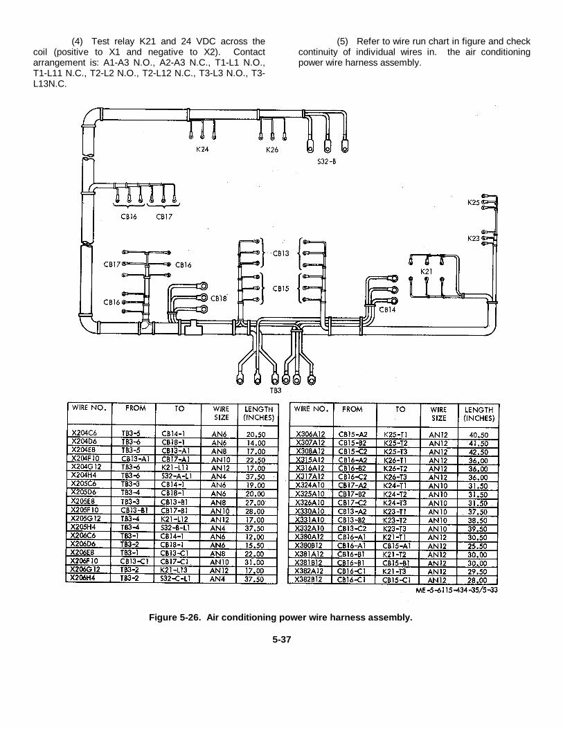
(4) Test relay K21 and 24 VDC across thecoil (positive to X1 and negative to X2). Contactarrangement is: A1-A3 N.O., A2-A3 N.C., T1-L1 N.O.,T1-L11 N.C., T2-L2 N.O., T2-L12 N.C., T3-L3 N.O., T3-L13N.C.
(5) Refer to wire run chart in figure and checkcontinuity of individual wires in. the air conditioningpower wire harness assembly.
Figure 5-26. Air conditioning power wire harness assembly.
5-37
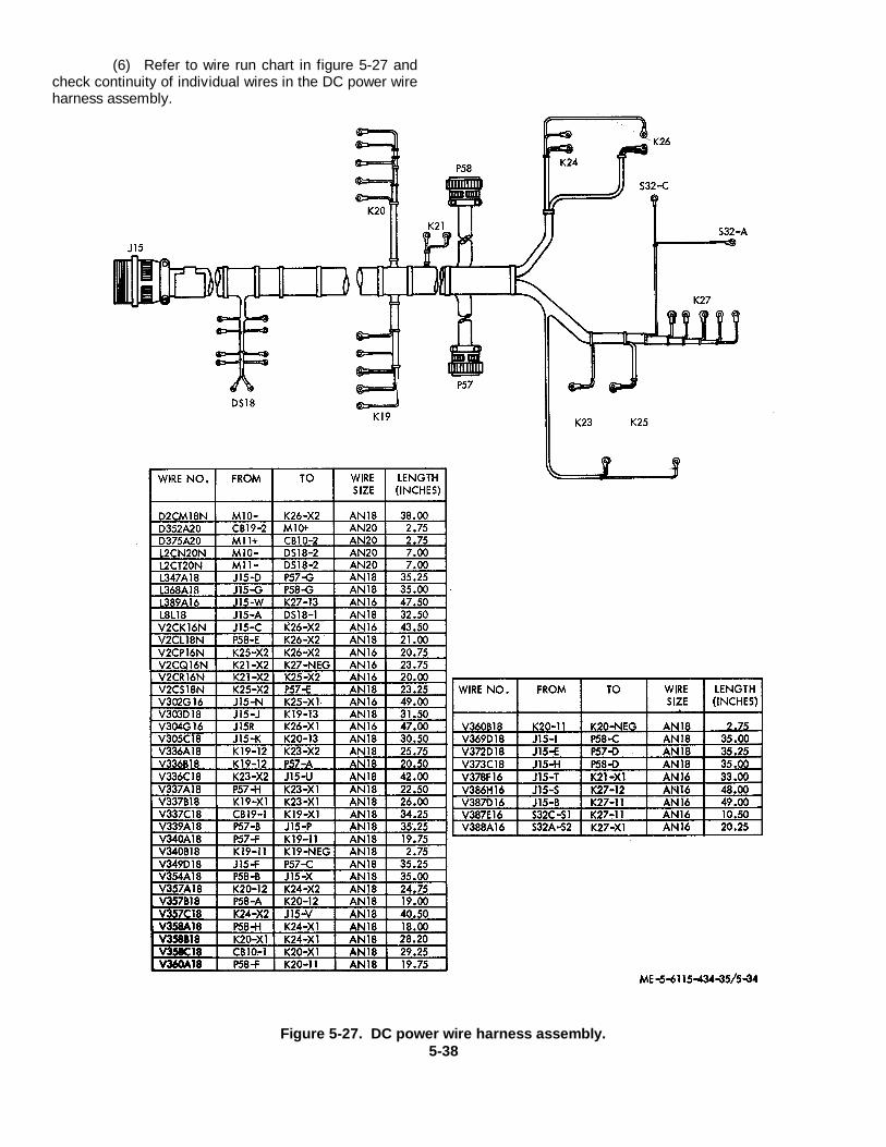
(6) Refer to wire run chart in figure 5-27 andcheck continuity of individual wires in the DC power wireharness assembly.
Figure 5-27. DC power wire harness assembly.5-38
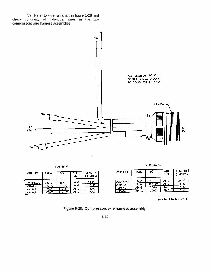
(7) Refer to wire run chart in figure 5-28 andcheck continuity of individual wires in the twocompressors wire harness assemblies.
Figure 5-28. Compressors wire harness assembly.
5-39
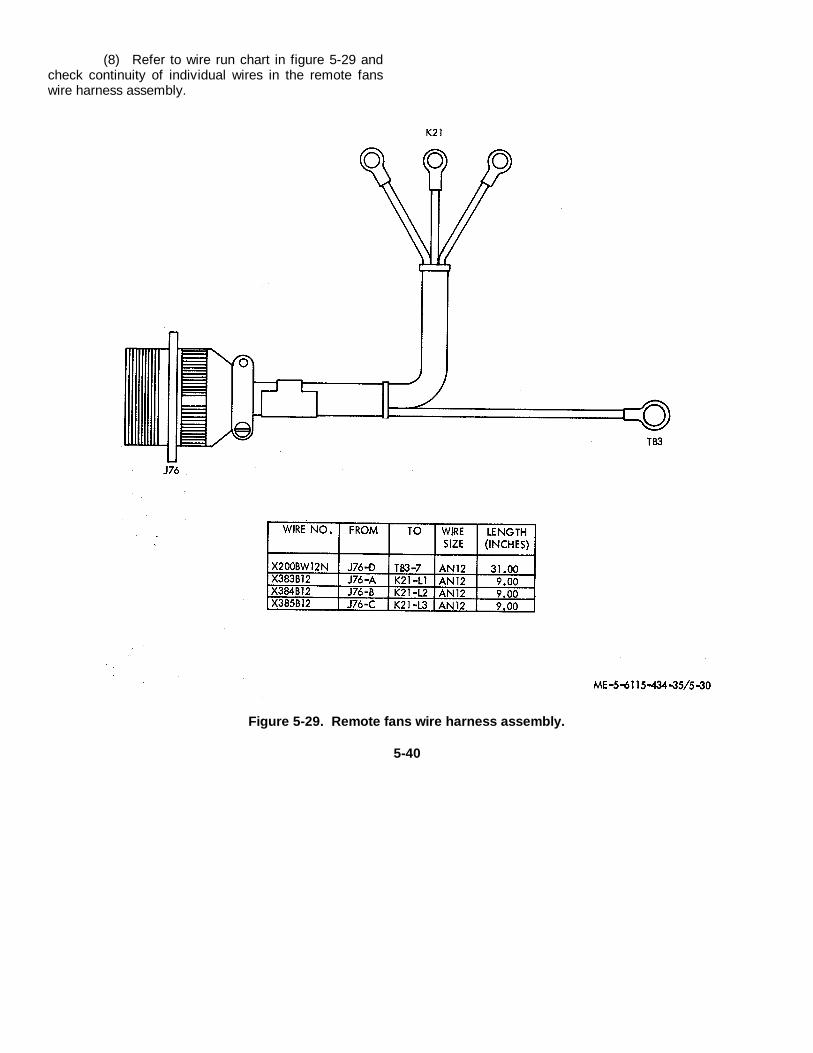
(8) Refer to wire run chart in figure 5-29 andcheck continuity of individual wires in the remote fanswire harness assembly.
Figure 5-29. Remote fans wire harness assembly.
5-40
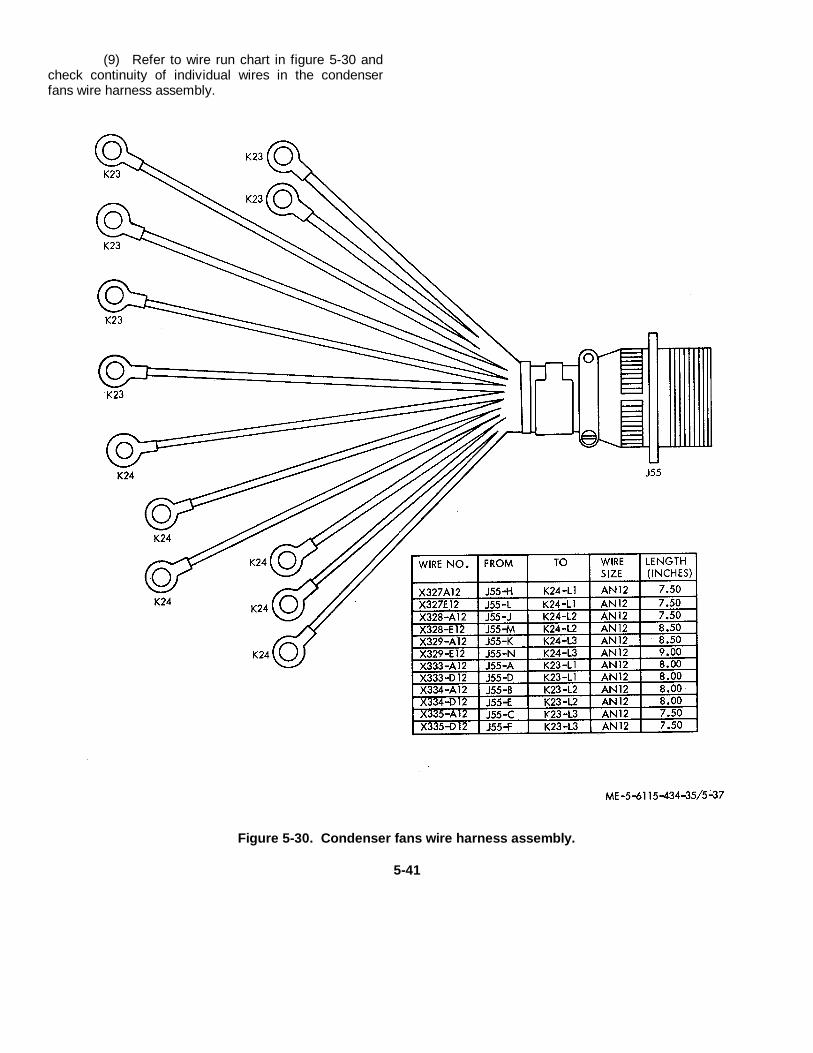
(9) Refer to wire run chart in figure 5-30 andcheck continuity of individual wires in the condenserfans wire harness assembly.
Figure 5-30. Condenser fans wire harness assembly.
5-41
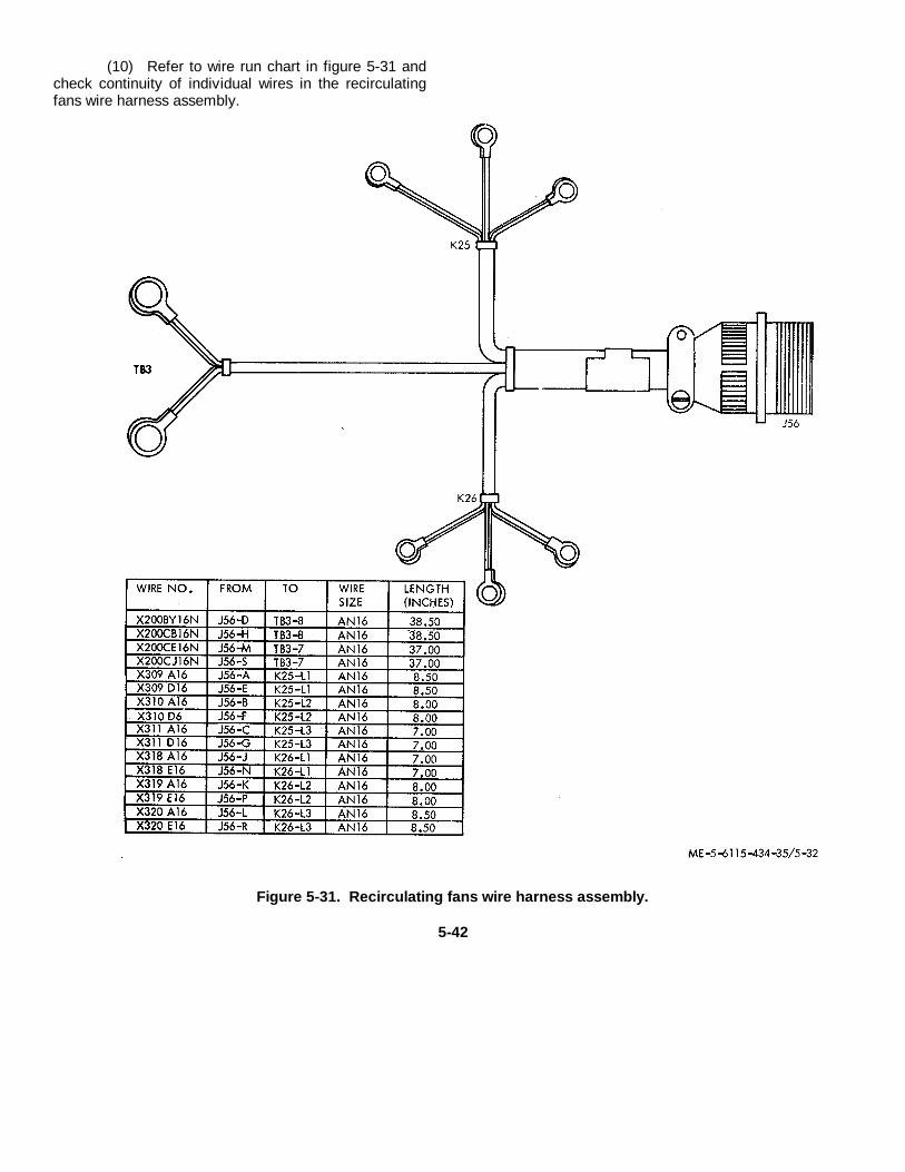
(10) Refer to wire run chart in figure 5-31 andcheck continuity of individual wires in the recirculatingfans wire harness assembly.
Figure 5-31. Recirculating fans wire harness assembly.
5-42
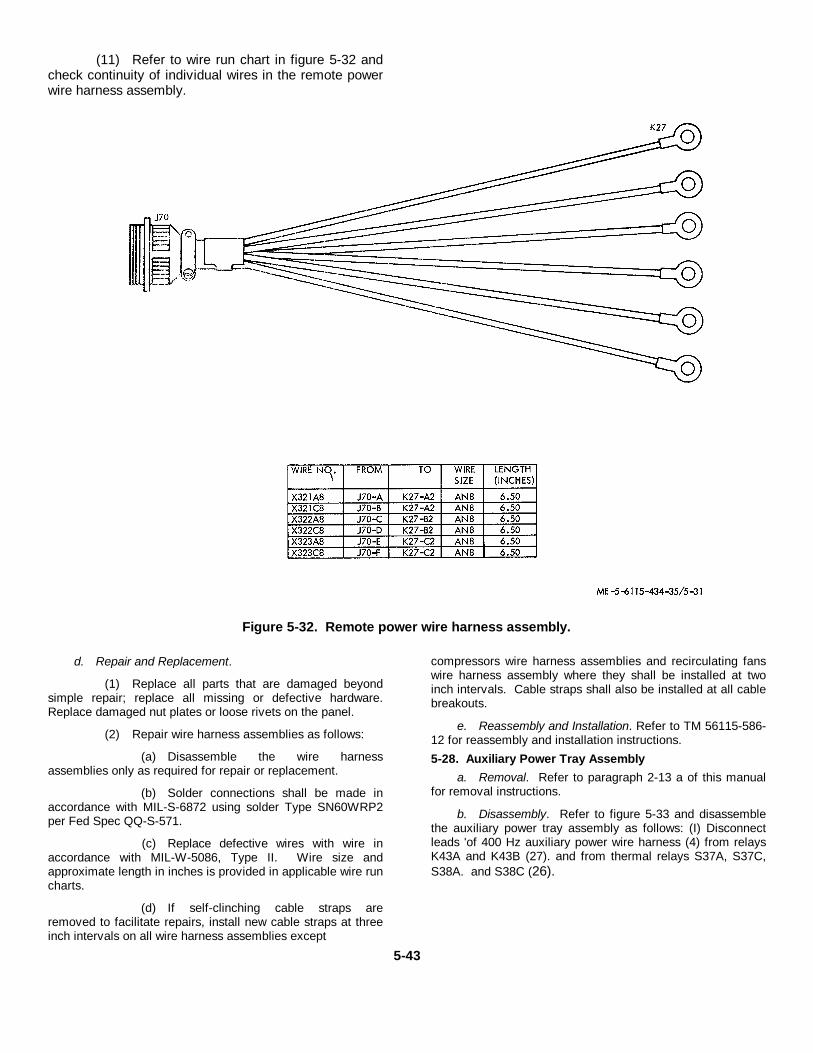
(11) Refer to wire run chart in figure 5-32 andcheck continuity of individual wires in the remote powerwire harness assembly.
Figure 5-32. Remote power wire harness assembly.
d. Repair and Replacement.
(1) Replace all parts that are damaged beyondsimple repair; replace all missing or defective hardware.Replace damaged nut plates or loose rivets on the panel.
(2) Repair wire harness assemblies as follows:
(a) Disassemble the wire harnessassemblies only as required for repair or replacement.
(b) Solder connections shall be made inaccordance with MIL-S-6872 using solder Type SN60WRP2per Fed Spec QQ-S-571.
(c) Replace defective wires with wire inaccordance with MIL-W-5086, Type II. Wire size andapproximate length in inches is provided in applicable wire runcharts.
(d) If self-clinching cable straps areremoved to facilitate repairs, install new cable straps at threeinch intervals on all wire harness assemblies except
compressors wire harness assemblies and recirculating fanswire harness assembly where they shall be installed at twoinch intervals. Cable straps shall also be installed at all cablebreakouts.
e. Reassembly and Installation. Refer to TM 56115-586-12 for reassembly and installation instructions.5-28. Auxiliary Power Tray Assembly
a. Removal. Refer to paragraph 2-13 a of this manualfor removal instructions.
b. Disassembly. Refer to figure 5-33 and disassemblethe auxiliary power tray assembly as follows: (I) Disconnectleads 'of 400 Hz auxiliary power wire harness (4) from relaysK43A and K43B (27). and from thermal relays S37A, S37C,S38A. and S38C (26).
5-43

(2) Remove nuts (1), washers (2) and screws(31 that attach wire harness connector. Carefully pulldisconnected wire harness (4) through grommets (28)and remove the harness.
(3) Remove the leads of the 400 Hz auxiliarywire harnesses (16 and 17) from relays K43A and K43B.Remove nuts (5), three washers (6), and screw (7) toremove each of the six capacitors (8
and 9) from the capacitor mounting brackets (15). Pushinsulated sleeving (10) back far enough to disconnectwire harness leads from the capacitors.
(4) Remove nuts (11), washers (12 and 13)and screws (14) to remove capacitor mounting brackets(15), wire harnesses (16 and 17) and gaskets (18).
5-44
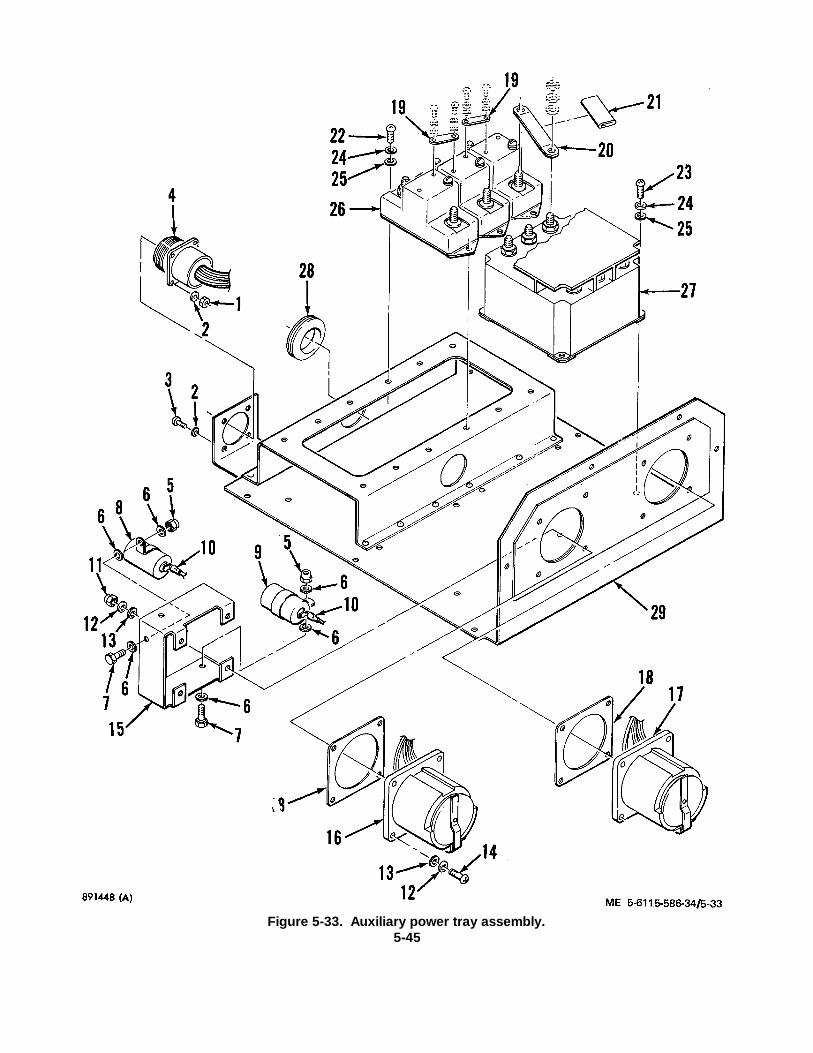
Figure 5-33. Auxiliary power tray assembly.5-45
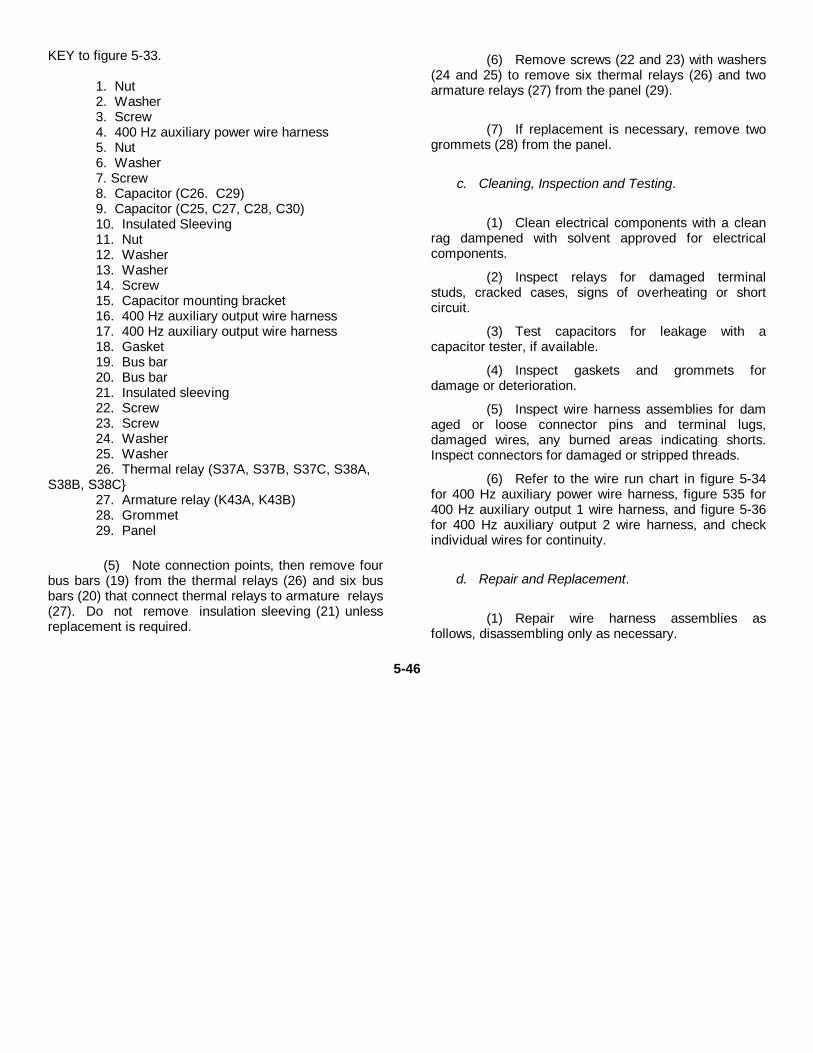
KEY to figure 5-33.
1. Nut2. Washer3. Screw4. 400 Hz auxiliary power wire harness5. Nut6. Washer7. Screw8. Capacitor (C26. C29)9. Capacitor (C25, C27, C28, C30)10. Insulated Sleeving11. Nut12. Washer13. Washer14. Screw15. Capacitor mounting bracket16. 400 Hz auxiliary output wire harness17. 400 Hz auxiliary output wire harness18. Gasket19. Bus bar20. Bus bar21. Insulated sleeving22. Screw23. Screw24. Washer25. Washer26. Thermal relay (S37A, S37B, S37C, S38A,
S38B, S38C}27. Armature relay (K43A, K43B)28. Grommet29. Panel
(5) Note connection points, then remove fourbus bars (19) from the thermal relays (26) and six busbars (20) that connect thermal relays to armature relays(27). Do not remove insulation sleeving (21) unlessreplacement is required.
(6) Remove screws (22 and 23) with washers(24 and 25) to remove six thermal relays (26) and twoarmature relays (27) from the panel (29).
(7) If replacement is necessary, remove twogrommets (28) from the panel.
c. Cleaning, Inspection and Testing.
(1) Clean electrical components with a cleanrag dampened with solvent approved for electricalcomponents.
(2) Inspect relays for damaged terminalstuds, cracked cases, signs of overheating or shortcircuit.
(3) Test capacitors for leakage with acapacitor tester, if available.
(4) Inspect gaskets and grommets fordamage or deterioration.
(5) Inspect wire harness assemblies for damaged or loose connector pins and terminal lugs,damaged wires, any burned areas indicating shorts.Inspect connectors for damaged or stripped threads.
(6) Refer to the wire run chart in figure 5-34for 400 Hz auxiliary power wire harness, figure 535 for400 Hz auxiliary output 1 wire harness, and figure 5-36for 400 Hz auxiliary output 2 wire harness, and checkindividual wires for continuity.
d. Repair and Replacement.
(1) Repair wire harness assemblies asfollows, disassembling only as necessary.
5-46
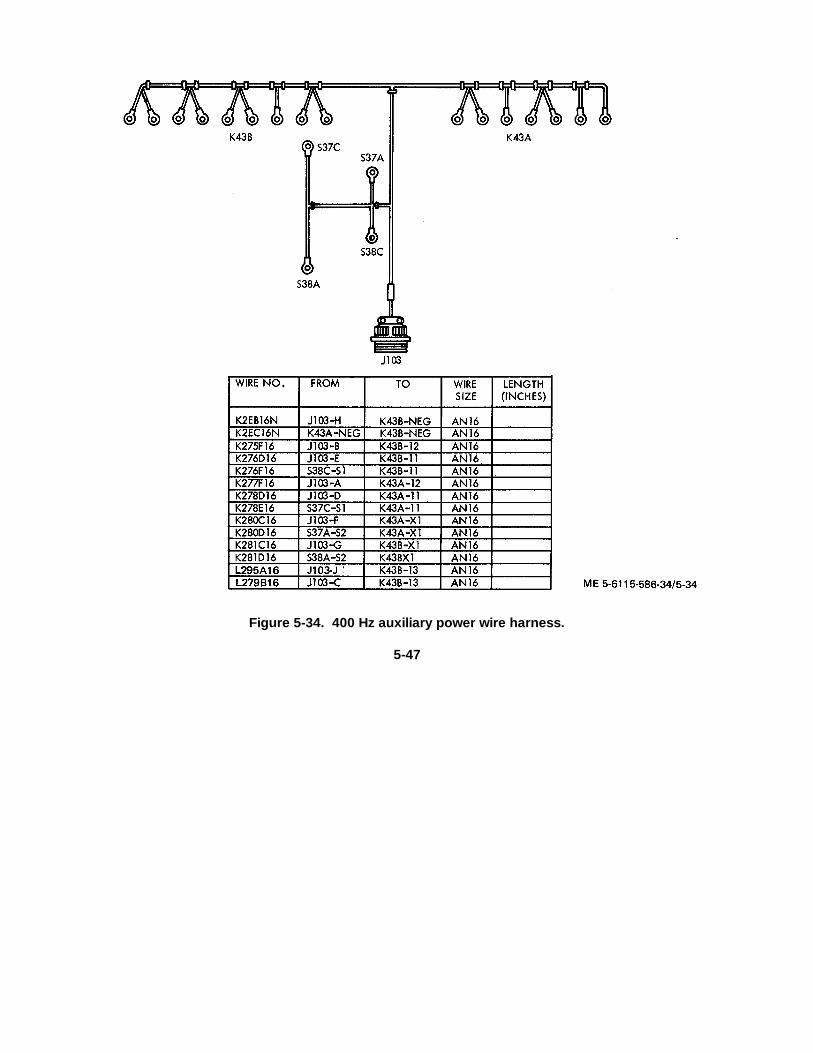
Figure 5-34. 400 Hz auxiliary power wire harness.
5-47
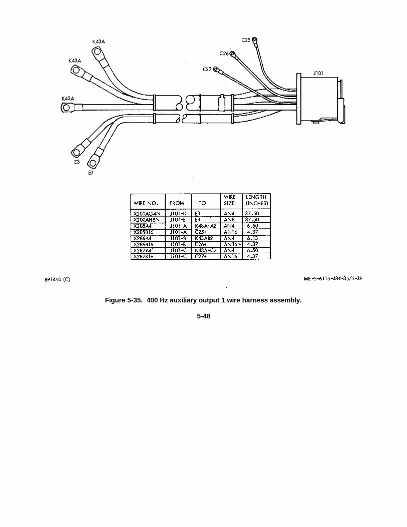
Figure 5-35. 400 Hz auxiliary output 1 wire harness assembly.
5-48
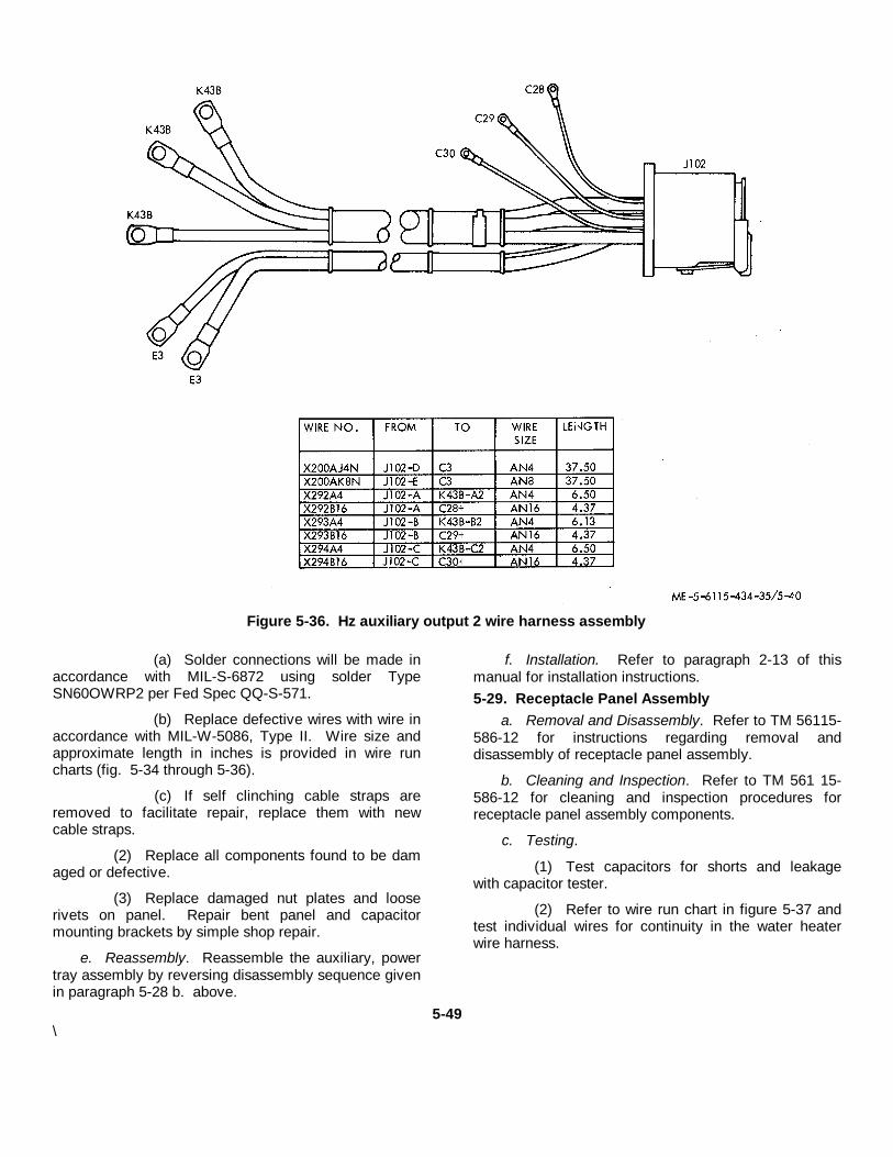
Figure 5-36. Hz auxiliary output 2 wire harness assembly
(a) Solder connections will be made inaccordance with MIL-S-6872 using solder TypeSN60OWRP2 per Fed Spec QQ-S-571.
(b) Replace defective wires with wire inaccordance with MIL-W-5086, Type II. Wire size andapproximate length in inches is provided in wire runcharts (fig. 5-34 through 5-36).
(c) If self clinching cable straps areremoved to facilitate repair, replace them with newcable straps.
(2) Replace all components found to be damaged or defective.
(3) Replace damaged nut plates and looserivets on panel. Repair bent panel and capacitormounting brackets by simple shop repair.
e. Reassembly. Reassemble the auxiliary, powertray assembly by reversing disassembly sequence givenin paragraph 5-28 b. above.
f. Installation. Refer to paragraph 2-13 of thismanual for installation instructions.5-29. Receptacle Panel Assembly
a. Removal and Disassembly. Refer to TM 56115-586-12 for instructions regarding removal anddisassembly of receptacle panel assembly.
b. Cleaning and Inspection. Refer to TM 561 15-586-12 for cleaning and inspection procedures forreceptacle panel assembly components.
c. Testing.
(1) Test capacitors for shorts and leakagewith capacitor tester.
(2) Refer to wire run chart in figure 5-37 andtest individual wires for continuity in the water heaterwire harness.
5-49\
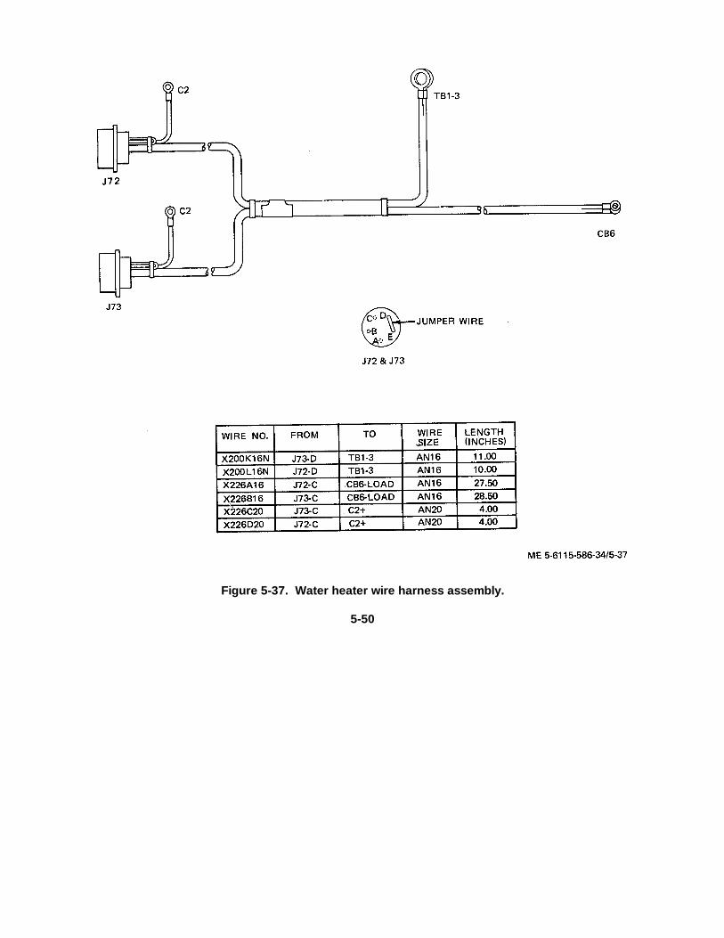
Figure 5-37. Water heater wire harness assembly.
5-50
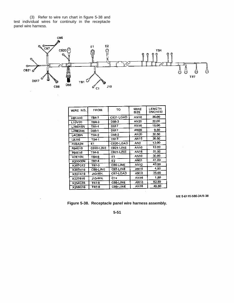
(3) Refer to wire run chart in figure 5-38 andtest individual wires for continuity in the receptaclepanel wire harness.
Figure 5-38. Receptacle panel wire harness assembly.
5-51
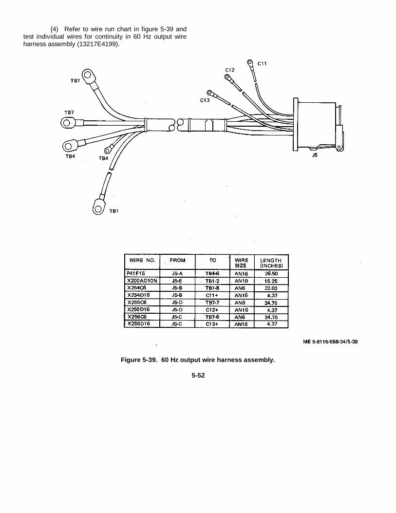
{4) Refer to wire run chart in figure 5-39 andtest individual wires for continuity in 60 Hz output wireharness assembly (13217E4199).
Figure 5-39. 60 Hz output wire harness assembly.
5-52
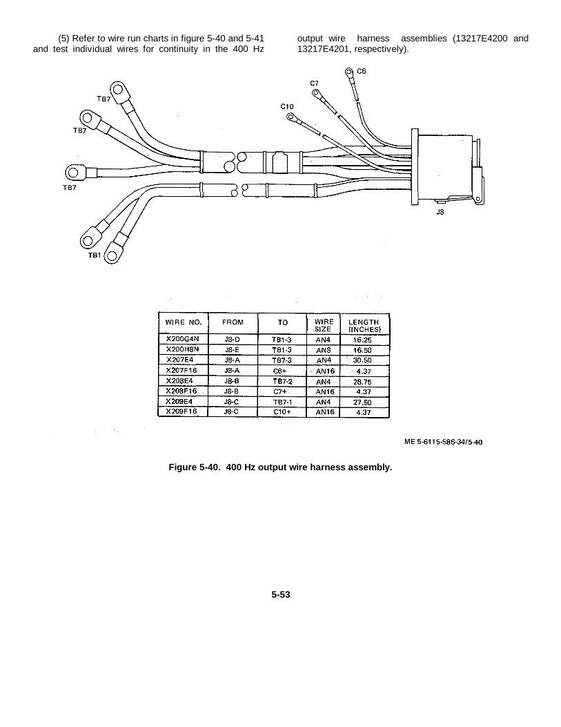
(5) Refer to wire run charts in figure 5-40 and 5-41and test individual wires for continuity in the 400 Hz
output wire harness assemblies (13217E4200 and13217E4201, respectively).
Figure 5-40. 400 Hz output wire harness assembly.
5-53
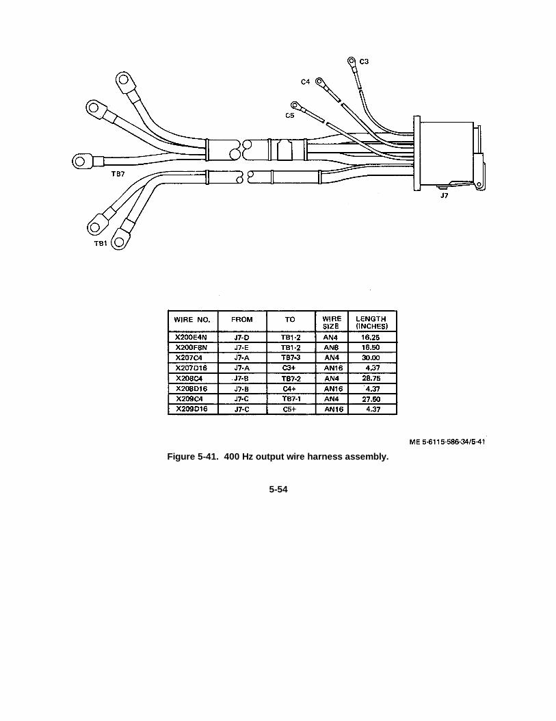
Figure 5-41. 400 Hz output wire harness assembly.
5-54
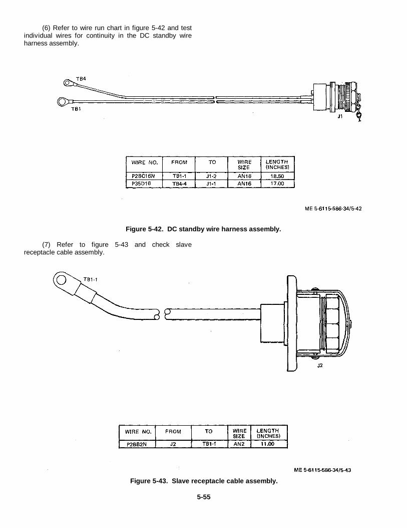
(6) Refer to wire run chart in figure 5-42 and testindividual wires for continuity in the DC standby wireharness assembly.
Figure 5-42. DC standby wire harness assembly.
(7) Refer to figure 5-43 and check slavereceptacle cable assembly.
Figure 5-43. Slave receptacle cable assembly.
5-55
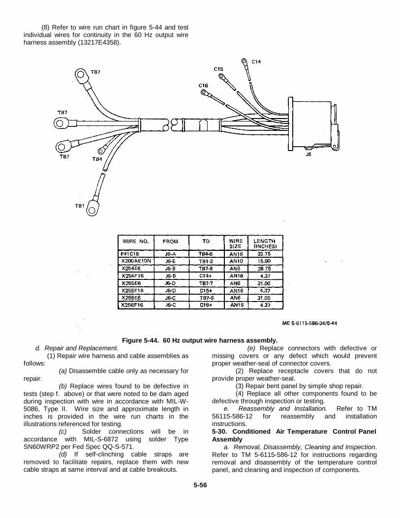
(8) Refer to wire run chart in figure 5-44 and testindividual wires for continuity in the 60 Hz output wireharness assembly (13217E4358).
Figure 5-44. 60 Hz output wire harness assembly.d. Repair and Replacement.
(1) Repair wire harness and cable assemblies asfollows:
(a) Disassemble cable only as necessary forrepair.
(b) Replace wires found to be defective intests (step f. above) or that were noted to be dam agedduring inspection with wire in accordance with MIL-W-5086, Type II. Wire size and approximate length ininches is provided in the wire run charts in theillustrations referenced for testing.
(c) Solder connections will be inaccordance with MIL-S-6872 using solder TypeSN60WRP2 per Fed Spec QQ-S-571.
(d) If self-clinching cable straps areremoved to facilitate repairs, replace them with newcable straps at same interval and at cable breakouts.
(e) Replace connectors with defective ormissing covers or any defect which would preventproper weather-seal of connector covers.
(2) Replace receptacle covers that do notprovide proper weather-seal.
(3) Repair bent panel by simple shop repair.(4) Replace all other components found to be
defective through inspection or testing.e. Reassembly and Installation. Refer to TM
56115-586-12 for reassembly and installationinstructions.5-30. Conditioned Air Temperature Control PanelAssembly
a. Removal, Disassembly, Cleaning and Inspection.Refer to TM 5-6115-586-12 for instructions regardingremoval and disassembly of the temperature controlpanel, and cleaning and inspection of components.
5-56
b. Testing.
(1) The heat range selector switches are rotary,2 pole, 4 position, non-shorting switches. An ohmmetercheck of open and closed circuits in each position maybe made to determine if switch is serviceable.
(2) The air temperature control switches operatewith the temperature sensors. Incorrect operation maybe due to failure of either the switch or the sensor. Astwo conditioned air systems are used, there are two heattemperature control switches and two cooled air
temperature control switches. If one system is notoperating properly. interchanging the like switches is asimple test. if the same system continues tomalfunction, the sensor or wiring is defective. If theopposite system malfunctions instead, the switch isdefective.
(3) Refer to the wire run chart in figure 5-45 andtest individual wires for continuity for the air conditioningand heat control panel wire harness assembly. Lampsare 24 VDC.
5-57
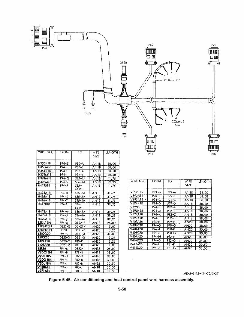
Figure 5-45. Air conditioning and heat control panel wire harness assembly.
5-58
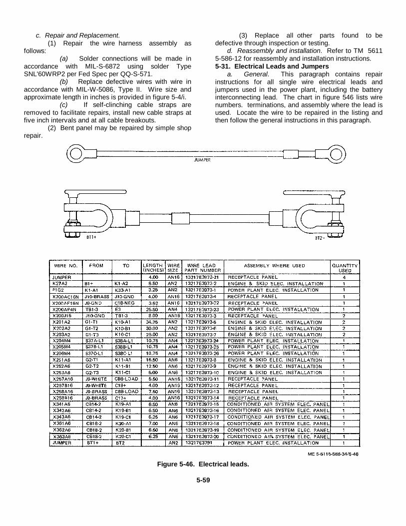
c. Repair and Replacement.(1) Repair the wire harness assembly as
follows:(a) Solder connections will be made in
accordance with MIL-S-6872 using solder TypeSNL'60WRP2 per Fed Spec per QQ-S-571.
(b) Replace defective wires with wire inaccordance with MIL-W-5086, Type II. Wire size andapproximate length in inches is provided in figure 5-4/i.
(c) If self-clinching cable straps areremoved to facilitate repairs, install new cable straps atfive inch intervals and at all cable breakouts.
(2) Bent panel may be repaired by simple shoprepair.
(3) Replace all other parts found to bedefective through inspection or testing.
d. Reassembly and installation. Refer to TM 56115-586-12 for reassembly and installation instructions.5-31. Electrical Leads and Jumpers
a. General. This paragraph contains repairinstructions for all single wire electrical leads andjumpers used in the power plant, including the batteryinterconnecting lead. The chart in figure 546 lists wirenumbers. terminations, and assembly where the lead isused. Locate the wire to be repaired in the listing andthen follow the general instructions in this paragraph.
Figure 5-46. Electrical leads.
5-59
b. Removal and Disassembly. Tag anddisconnect electrical lead. Disassemble only for repair.
c. Inspection and Repair.(1) Inspect electrical lead for damaged or loose
terminals, damaged wire or insulation.(2) Repair leads by replacing defective wire and
terminals. S' ire size and approximate length in inchesis provided.
(3) If lugs on battery electrical lead must bereplaced, unscrew them from adapter and install newlugs. If adapter must be replaced, solder to wire inaccordance with MIL-S-6872 using solder TypeSN60OWRP2 per Fed Spec QQ-S-571.
d. Installation. Reconnect electrical leads inlocations as tagged or utilize termination data in wire runchart in figure 5-46.
Section II. ENGINE AND SKID ELECTRICAL INSTALLATION
5-32. GeneralThe engine and skid electrical installation consists of theupper electric power chassis assembly, the lowerelectric power chassis assembly and interconnectingwire harness assemblies. There are four wire harnessassemblies in the installation, the engine skid wireharness on the lower power chassis, the power wireharness, and the battery wire harness. The engine wireharness repair instructions are provided in paragraph 3-2 of this manual. Electrical leads and jumpers areincluded in -paragraph 5-31 above.
5-33. Upper Electric Power Chassis Assembly
a. Removal and Disassembly. Refer to TM 561 115-586-12 for instructions regarding removal of the upperelectric power chassis assembly and removal ofcomponents.
b. Cleaning, Inspection and Testing. Cleaning,inspection, and testing instructions are provided in TM5-6115-586-12. Also refer to figure FO-2 located inback of manual) for a wire run chart for the engine skidpower unit wire harness as an aid to testing. Testdiodes on wire harness ICR through CR20) with anohmmeter; a serviceable diode will indicate a lowresistance in one direction (forward biased! and asignificantly higher resistance when ohmmeter leadconnections are reversed (reverse bias ). A diode thatindicates an open circuit or near the same resistance inboth directions is defective.
c. Repair and Replacement.
(1) Repair the wire harness assembly as follows:
(a) When replacing diodes, use a pair ofpliers or a clip as a "heat sink" to avoid damage to thenew-diode when soldering it to the wire harness lead.
Be certain that bushings and mica washers are correctlyinstalled on diodes at assembly.
(b) Solder connections will be made inaccordance with MIL-S-6872 using solder TypeSN60OWRP2 per Fed Spec QQ-S-571.
(c) Replace defective wires with wire inaccordance with MIL-W-5086, Type II. Wire size andapproximate length in inches is provided in figure FO-2.
(d) If self-clinching cable straps areremoved to facilitate repairs, install new cable straps atreassembly.
(2) Replace damaged nut plates and loose ormissing rivets on chassis. Repair bent chassis bysimple shop repair.
(3) Replace all other parts found to be defectivethrough inspection or testing. Defective battery chargerand voltage regulators shall be replaced and defectiveunits sent to depot maintenance facilities for repair.
d. Reassembly and Installation. Refer to TM56115-586-12 for reassembly and installationinstructions.
5-34. Lower Electric Power Chassis Assembly
a. Removal and Disassembly. Refer to TM 56115-586-12 for removal and disassembly instructions.
b. Cleaning, Inspection and Testing. Cleaning,inspection, and testing instructions are provided in TM5-6115-586-12. Also refer to figure 5-47 for a wire runchart for the engine skid wire harness as an aid totesting.
5-60
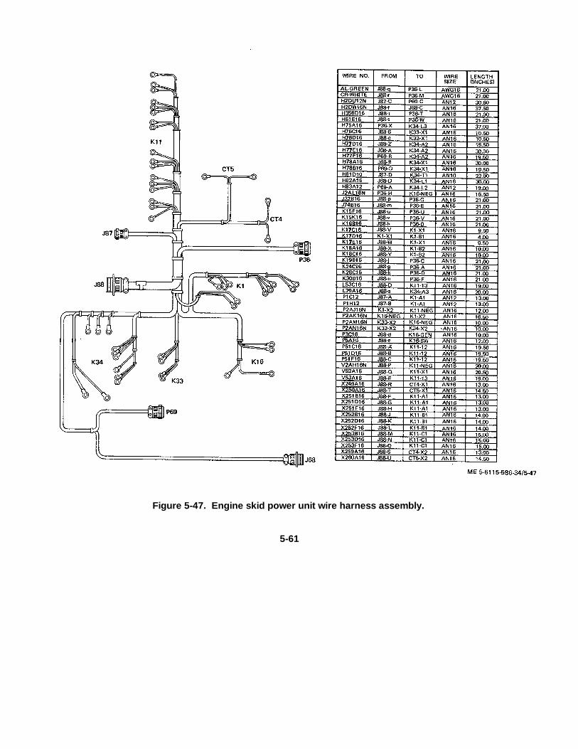
Figure 5-47. Engine skid power unit wire harness assembly.
5-61
c. Repair and Replacement.(1) Repair the wire harness assembly as follows:
(a) Solder connections will be made inaccordance with MIL-S-6872 using solder TypeSN60OWRP2 per Fed Spec QQ-S-57 1.
(b) Replace defective wires with wire inaccordance with MIL-W-5086, Type II. Wire size andapproximate length in inches is provided in figure 5-4li.
(c) If self-clinching cable straps areremoved to facilitate repairs, replace with new straps atsame interval and at all cable breakouts.
(2) Replace damaged nut plates and loose ormissing rivets on chassis. Repair bent chassis bysimple shop repair.
(3) Replace all other parts found to be defectivethrough inspection or testing. Defective battery charger
and voltage regulators shall be replaced and defectiveunits sent to depot maintenance facilities for repair.
d. Reassembly and Installation. Refer to TM 5-6115-586-12 for reassembly and installationinstructions.
5-35. Power Wire Harness Assembly (13217E4001)
a. Removal. Refer to figure 5-48; tag anddisconnect the power wire harness assembly as follows:
(1) Disconnect the wire harness leads to GI, KII.K12, and SI0.
(2) Remove lockwires and disconnect the threeconnectors (P49, P50 and P51); then remove the w ireharness assembly.
5-62

Figure 5-48. Power wire harness assemblyb. Disassembly. After inspection and testing,
disassemble the wire harness only as required for repairor replacement.
c. Cleaning and Inspection.(1) Clean wire harness with a clean, lint-free
cloth moistened with an approved solvent and drythoroughly.
(2) Inspect for damaged or loose connector pins,damaged wires, and loose or damaged terminal lugs.Check for any evidence of burned areas indicatingshorts. Inspect connectors for damaged or strippedthreads.
d. Testing. Refer to the wire run chart in figure 5-48and check individual wires for continuity.
e. Repair, Replacement and Reassembly.(1) Solder connections will be made in
accordance with MIL-S-6872 using solder TypeSN60WRP2 per Fed Spec QQ-S-571.
(2) Replace defective wires with wire inaccordance with MIL-W-5086, Type II. Wire size andapproximate length in inches is provided in figure 5-48.
(3) If self-clinching cable straps are removed tofacilitate repairs, install new cable straps at sameintervals and at all cable breakouts.
5-63
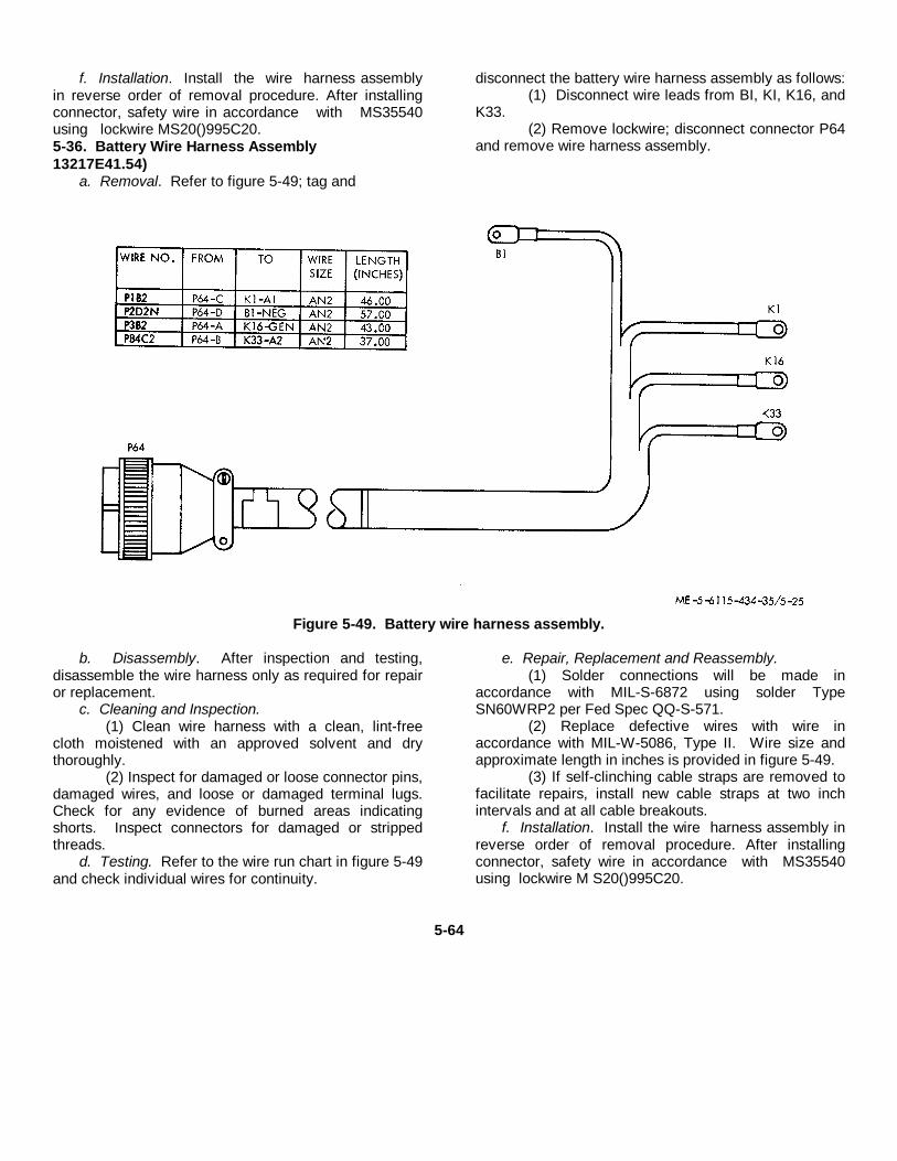
f. Installation. Install the wire harness assemblyin reverse order of removal procedure. After installingconnector, safety wire in accordance with MS35540using lockwire MS20()995C20.5-36. Battery Wire Harness Assembly13217E41.54)
a. Removal. Refer to figure 5-49; tag and
disconnect the battery wire harness assembly as follows:(1) Disconnect wire leads from BI, KI, K16, and
K33.(2) Remove lockwire; disconnect connector P64
and remove wire harness assembly.
Figure 5-49. Battery wire harness assembly.
b. Disassembly. After inspection and testing,disassemble the wire harness only as required for repairor replacement.
c. Cleaning and Inspection.(1) Clean wire harness with a clean, lint-free
cloth moistened with an approved solvent and drythoroughly.
(2) Inspect for damaged or loose connector pins,damaged wires, and loose or damaged terminal lugs.Check for any evidence of burned areas indicatingshorts. Inspect connectors for damaged or strippedthreads.
d. Testing. Refer to the wire run chart in figure 5-49and check individual wires for continuity.
e. Repair, Replacement and Reassembly.(1) Solder connections will be made in
accordance with MIL-S-6872 using solder TypeSN60WRP2 per Fed Spec QQ-S-571.
(2) Replace defective wires with wire inaccordance with MIL-W-5086, Type II. Wire size andapproximate length in inches is provided in figure 5-49.
(3) If self-clinching cable straps are removed tofacilitate repairs, install new cable straps at two inchintervals and at all cable breakouts.
f. Installation. Install the wire harness assembly inreverse order of removal procedure. After installingconnector, safety wire in accordance with MS35540using lockwire M S20()995C20.
5-64

CHAPTER 6
REPAIR OF CONDITIONED AIR COOLING SYSTEM
Section I. TUBE ASSEMBLIES AND PLUMBING FITTINGS
6-1. GeneralThe conditioned air cooling systems consists of twoseparate air conditioning refrigeration systems. Eachseparate system consists of compressor, evaporator,condenser, receiver, and tubing interconnecting thesecomponents.6-2. Tube Assemblies, Fittings, and SolenoidValves
a. Removal. Remove the tube assemblies, fittings,and valves by following the ascending numericalsequence, of the index numbers I through 187 assignedto figure 6-1.
Note. Each tube assembly is independent of the othersand it is not necessary to completely disassemble the systemto repair or replace any one tube assembly. Only the tuberequiring such repair need be removed.
b. Cleaning, Inspection and Repair.(1) Clean tube assemblies and fittings with
kerosene and degrease with trichlorethylene IMILT-7003) heated to 1600 to 1800 F in a vapor degreaser.
Warning: Trichlorethylene (MIL-T-7003) is toxicand should be used only in a well ventilated area.Failure to observe this warning may result inserious harm or death to personnel.
(2) Inspect flared tube fittings and hardware forstripped, crossed, peened, or otherwise damagedthreads.
(3) Inspect tube assemblies for cracks, dents,corrosion, or other obvious damage.
6-1
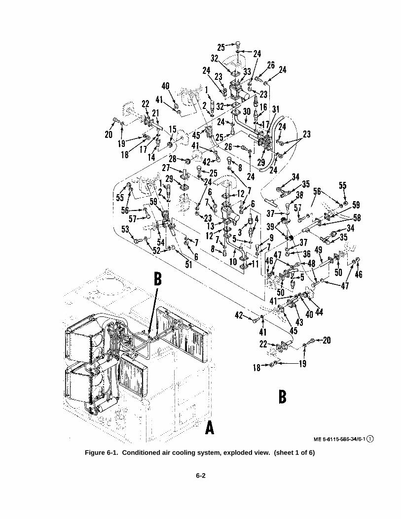
Figure 6-1. Conditioned air cooling system, exploded view. (sheet 1 of 6)
6-2
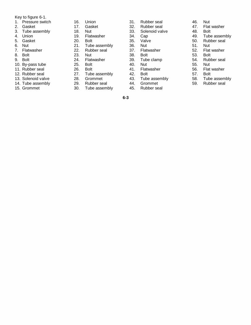
Key to figure 6-1.1. Pressure switch 16. Union 31. Rubber seal 46. Nut2. Gasket 17. Gasket 32. Rubber seal 47. Flat washer3. Tube assembly 18. Nut 33. Solenoid valve 48. Bolt4. Union 19. Flatwasher 34. Cap 49. Tube assembly5. Gasket 20. Bolt 35. Valve 50. Rubber seal6. Nut 21. Tube assembly 36. Nut 51. Nut7. Flatwasher 22. Rubber seal 37. Flatwasher 52. Flat washer8. Bolt 23. Nut 38. Bolt 53. Bolt9. Bolt 24. Flatwasher 39. Tube clamp 54. Rubber seal10. By-pass tube 25. Bolt 40. Nut 55. Nut11. Rubber seal 26. Bolt 41. Flatwasher 56. Flat washer12. Rubber seal 27. Tube assembly 42. Bolt 57. Bolt13. Solenoid valve 28. Grommet 43. Tube assembly 58. Tube assembly14. Tube assembly 29. Rubber seal 44. Grommet 59. Rubber seal15. Grommet 30. Tube assembly 45. Rubber seal
6-3
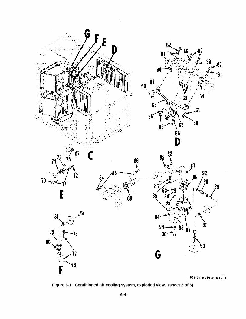
Figure 6-1. Conditioned air cooling system, exploded view. (sheet 2 of 6)
6-4

Key to figure 6-1-Continued:69. Rubber seal 69. Tube assembly 79. Tube assembly 89. Tube Assembly60. Nut 70. Nut 80. Rubber seal 90. Union61. Flat washer 71. Flat washer 81. Grommet 91. Grommet62. Bolt 72. Bolt 82. Cap 92. Gasket63. Tube assembly 73. Tube assembly 83. Valve 93. Nut64. Rubber seal 74. Rubber seal 84. Nut 94. Flat washer65. Nut 75. Grommet 85. Flat washer 95. Spacer66. Flat washer 76. Nut 86. Bolt 0)6. Bolt67. Bolt 77. Flat washer 87. Tube assembly 97. Compressor68. Tube assembly 78. Bolt 88. Rubber seal 98. Spacer
6-5
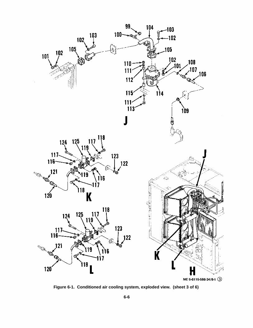
Figure 6-1. Conditioned air cooling system, exploded view. (sheet 3 of 6)
6-6

Key to figure 6-1-Continued: 105. Rubber seal 112. Spacer 119. Rubber seal99. Cap 106. Tube assembly 113. Bolt 120. Tube assembly100. Valve 107. Union 114. Compressor 121. Check valve101. Nut 108. Gasket 115. Spacer 122. Nut102. Flat washer 109. Grommet 116. Nut 123. Flat washer103. Bolt 110. Nut 117. Flat washer 124. Bolt104. Tube assembly 111. Flat washer 118. Bolt 125. Solenoid valve
6-7
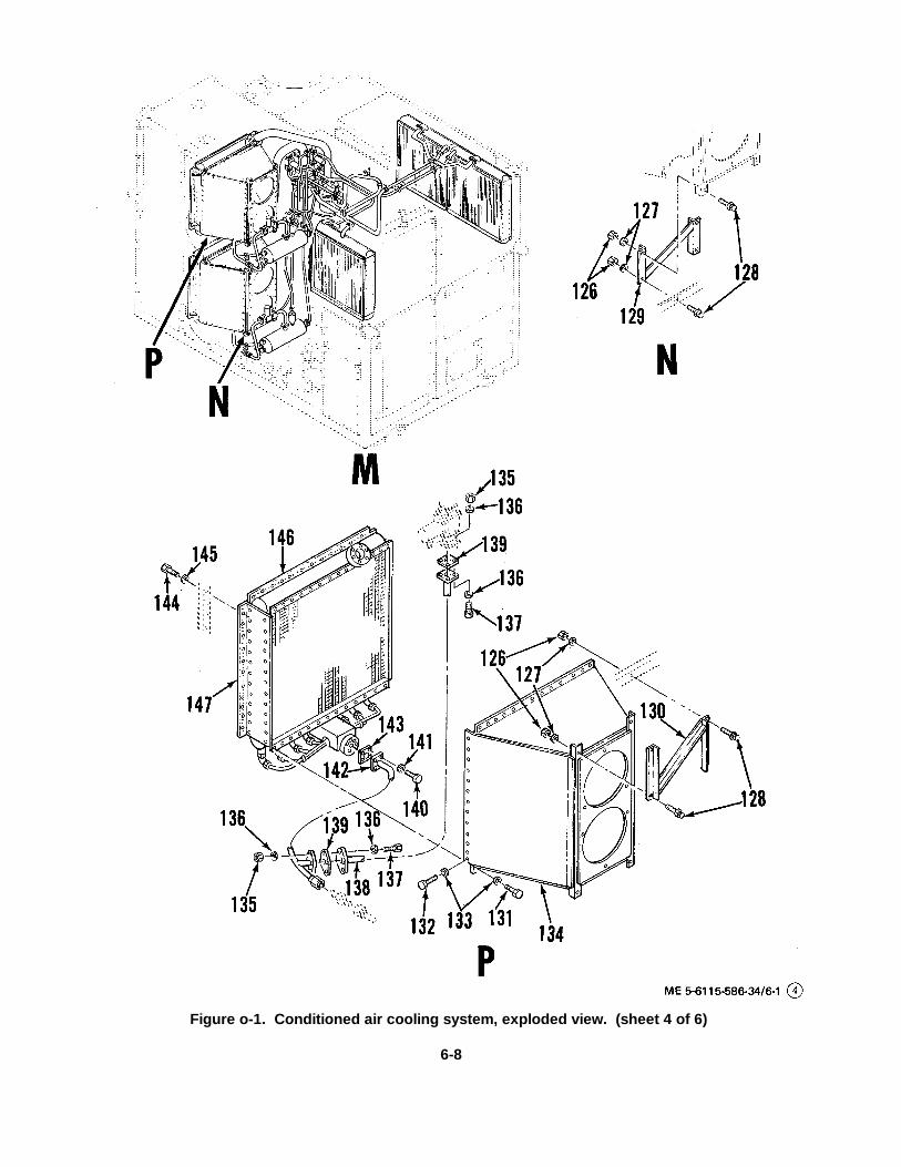
Figure o-1. Conditioned air cooling system, exploded view. (sheet 4 of 6)
6-8

Keyto figure 6-1-Continued: 131. Bolt 137. Bolt126. Nut 132. Bolt 138. Tube assembly 143. Rubber seal127. Flat washer 133. Flat washer 139. Rubber seal 144. Bolt128. Bolt 1:34. Fan housing 140. Bolt 145. Flat washer120. Brace 135. Nut 141. Flat washer 146. Rubber strip130. Brace 136. Flat washer 142. Tube assembly 147. Evaporator
6-9
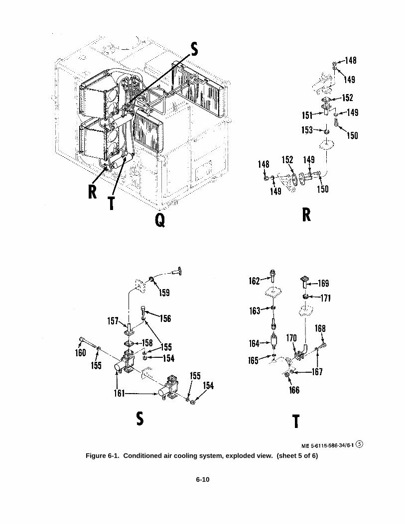
Figure 6-1. Conditioned air cooling system, exploded view. (sheet 5 of 6)
6-10

KEY to figure 6-1-Continued:148. Nut 154. Nut 160. Bolt 166. Nut149. Flat washer 155. Flat washer 161. Solenoid valve 167. Lockwasher150. Bolt 156. Bolt 162. Tube assembly 168. Bolt151. Tube assembly 157. Tube assembly 163. Grommet 169. Tube assembly152. Rubber seal 158. Rubber seal 164. Dehydrator 170. Rubber seal153. Grommet 159. Grommet 165. Gasket 171. Grommet
6-11
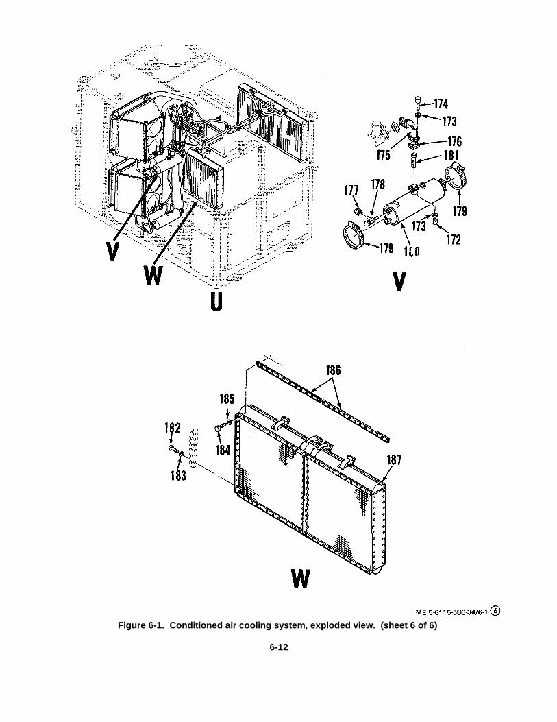
Figure 6-1. Conditioned air cooling system, exploded view. (sheet 6 of 6)
6-12
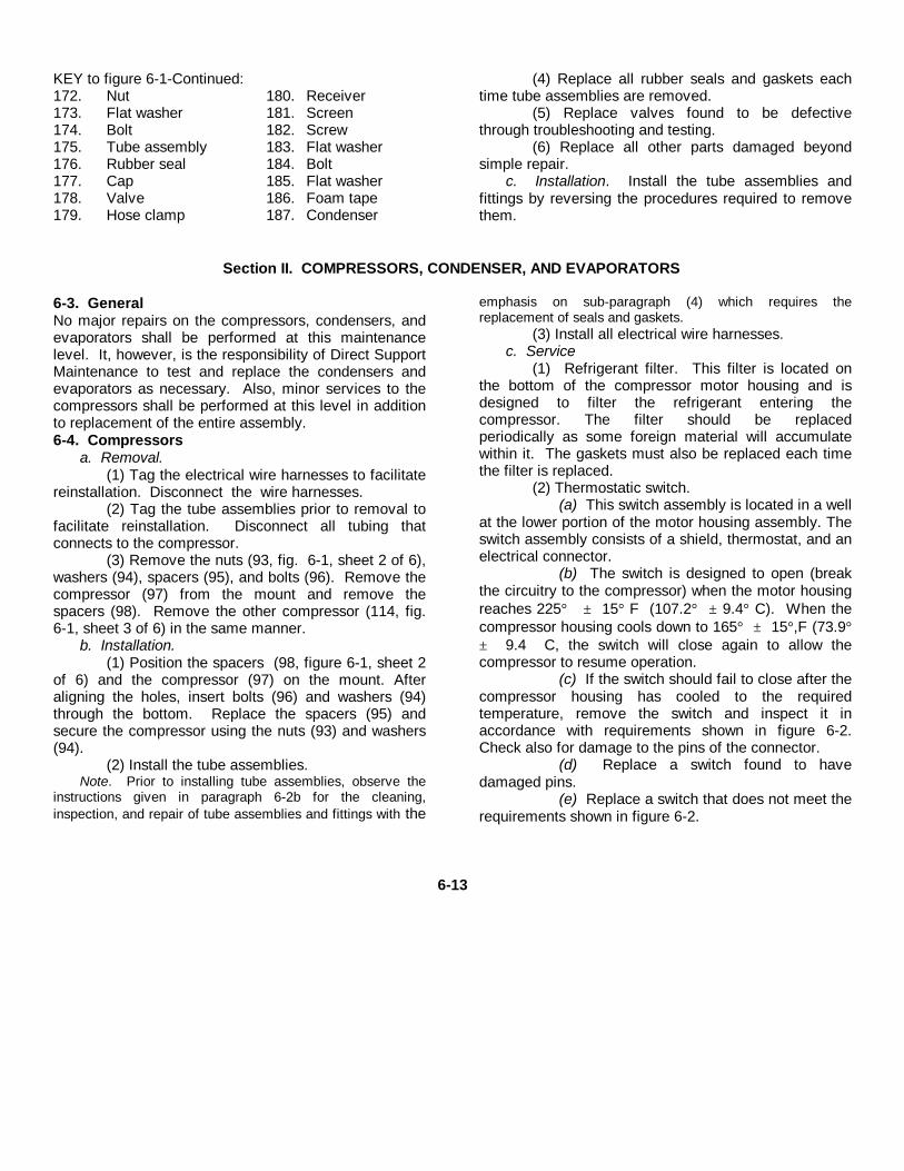
KEY to figure 6-1-Continued:172. Nut 180. Receiver173. Flat washer 181. Screen174. Bolt 182. Screw175. Tube assembly 183. Flat washer176. Rubber seal 184. Bolt177. Cap 185. Flat washer178. Valve 186. Foam tape179. Hose clamp 187. Condenser
(4) Replace all rubber seals and gaskets eachtime tube assemblies are removed.
(5) Replace valves found to be defectivethrough troubleshooting and testing.
(6) Replace all other parts damaged beyondsimple repair.
c. Installation. Install the tube assemblies andfittings by reversing the procedures required to removethem.
Section II. COMPRESSORS, CONDENSER, AND EVAPORATORS
6-3. GeneralNo major repairs on the compressors, condensers, andevaporators shall be performed at this maintenancelevel. It, however, is the responsibility of Direct SupportMaintenance to test and replace the condensers andevaporators as necessary. Also, minor services to thecompressors shall be performed at this level in additionto replacement of the entire assembly.6-4. Compressors
a. Removal.(1) Tag the electrical wire harnesses to facilitate
reinstallation. Disconnect the wire harnesses.(2) Tag the tube assemblies prior to removal to
facilitate reinstallation. Disconnect all tubing thatconnects to the compressor.
(3) Remove the nuts (93, fig. 6-1, sheet 2 of 6),washers (94), spacers (95), and bolts (96). Remove thecompressor (97) from the mount and remove thespacers (98). Remove the other compressor (114, fig.6-1, sheet 3 of 6) in the same manner.
b. Installation.(1) Position the spacers (98, figure 6-1, sheet 2
of 6) and the compressor (97) on the mount. Afteraligning the holes, insert bolts (96) and washers (94)through the bottom. Replace the spacers (95) andsecure the compressor using the nuts (93) and washers(94).
(2) Install the tube assemblies.Note. Prior to installing tube assemblies, observe the
instructions given in paragraph 6-2b for the cleaning,inspection, and repair of tube assemblies and fittings with the
emphasis on sub-paragraph (4) which requires thereplacement of seals and gaskets.
(3) Install all electrical wire harnesses.c. Service
(1) Refrigerant filter. This filter is located onthe bottom of the compressor motor housing and isdesigned to filter the refrigerant entering thecompressor. The filter should be replacedperiodically as some foreign material will accumulatewithin it. The gaskets must also be replaced each timethe filter is replaced.
(2) Thermostatic switch.(a) This switch assembly is located in a well
at the lower portion of the motor housing assembly. Theswitch assembly consists of a shield, thermostat, and anelectrical connector.
(b) The switch is designed to open (breakthe circuitry to the compressor) when the motor housingreaches 225° ± 15° F (107.2° ± 9.4° C). When thecompressor housing cools down to 165° ± 15°,F (73.9°± 9.4 C, the switch will close again to allow thecompressor to resume operation.
(c) If the switch should fail to close after thecompressor housing has cooled to the requiredtemperature, remove the switch and inspect it inaccordance with requirements shown in figure 6-2.Check also for damage to the pins of the connector.
(d) Replace a switch found to havedamaged pins.
(e) Replace a switch that does not meet therequirements shown in figure 6-2.
6-13
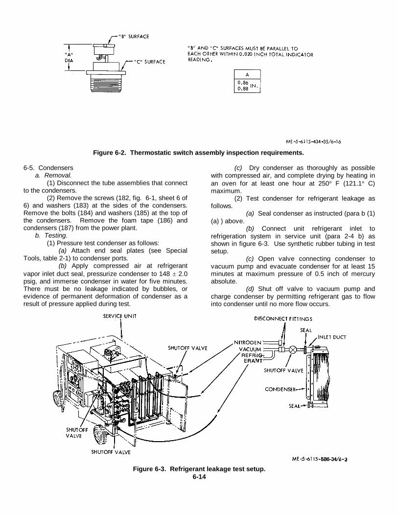
Figure 6-2. Thermostatic switch assembly inspection requirements.
6-5. Condensersa. Removal.
(1) Disconnect the tube assemblies that connectto the condensers.
(2) Remove the screws (182, fig. 6-1, sheet 6 of6) and washers (183) at the sides of the condensers.Remove the bolts (184) and washers (185) at the top ofthe condensers. Remove the foam tape (186) andcondensers (187) from the power plant.
b. Testing.(1) Pressure test condenser as follows:
(a) Attach end seal plates (see SpecialTools, table 2-1) to condenser ports.
(b) Apply compressed air at refrigerantvapor inlet duct seal, pressurize condenser to 148 ± 2.0psig, and immerse condenser in water for five minutes.There must be no leakage indicated by bubbles, orevidence of permanent deformation of condenser as aresult of pressure applied during test.
(c) Dry condenser as thoroughly as possiblewith compressed air, and complete drying by heating inan oven for at least one hour at 250° F (121.1° C)maximum.
(2) Test condenser for refrigerant leakage asfollows.
(a) Seal condenser as instructed (para b (1)(a) ) above.
(b) Connect unit refrigerant inlet torefrigeration system in service unit (para 2-4 b) asshown in figure 6-3. Use synthetic rubber tubing in testsetup.
(c) Open valve connecting condenser tovacuum pump and evacuate condenser for at least 15minutes at maximum pressure of 0.5 inch of mercuryabsolute.
(d) Shut off valve to vacuum pump andcharge condenser by permitting refrigerant gas to flowinto condenser until no more flow occurs.
Figure 6-3. Refrigerant leakage test setup.6-14
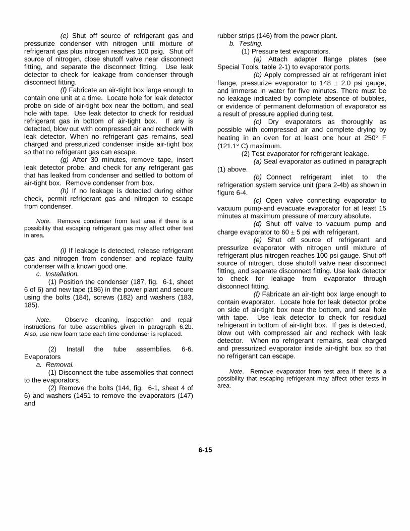
(e) Shut off source of refrigerant gas andpressurize condenser with nitrogen until mixture ofrefrigerant gas plus nitrogen reaches 100 psig. Shut offsource of nitrogen, close shutoff valve near disconnectfitting, and separate the disconnect fitting. Use leakdetector to check for leakage from condenser throughdisconnect fitting.
(f) Fabricate an air-tight box large enough tocontain one unit at a time. Locate hole for leak detectorprobe on side of air-tight box near the bottom, and sealhole with tape. Use leak detector to check for residualrefrigerant gas in bottom of air-tight box. If any isdetected, blow out with compressed air and recheck withleak detector. When no refrigerant gas remains, sealcharged and pressurized condenser inside air-tight boxso that no refrigerant gas can escape.
(g) After 30 minutes, remove tape, insertleak detector probe, and check for any refrigerant gasthat has leaked from condenser and settled to bottom ofair-tight box. Remove condenser from box.
(h) If no leakage is detected during eithercheck, permit refrigerant gas and nitrogen to escapefrom condenser.
Note. Remove condenser from test area if there is apossibility that escaping refrigerant gas may affect other testin area.
(i) If leakage is detected, release refrigerantgas and nitrogen from condenser and replace faultycondenser with a known good one.
c. Installation.(1) Position the condenser (187, fig. 6-1, sheet
6 of 6) and new tape (186) in the power plant and secureusing the bolts (184), screws (182) and washers (183,185).
Note. Observe cleaning, inspection and repairinstructions for tube assemblies given in paragraph 6.2b.Also, use new foam tape each time condenser is replaced.
(2) Install the tube assemblies. 6-6.Evaporators
a. Removal.(1) Disconnect the tube assemblies that connect
to the evaporators.(2) Remove the bolts (144, fig. 6-1, sheet 4 of
6) and washers (1451 to remove the evaporators (147)and
rubber strips (146) from the power plant.b. Testing.
(1) Pressure test evaporators.(a) Attach adapter flange plates (see
Special Tools, table 2-1) to evaporator ports.(b) Apply compressed air at refrigerant inlet
flange, pressurize evaporator to 148 ± 2.0 psi gauge,and immerse in water for five minutes. There must beno leakage indicated by complete absence of bubbles,or evidence of permanent deformation of evaporator asa result of pressure applied during test.
(c) Dry evaporators as thoroughly aspossible with compressed air and complete drying byheating in an oven for at least one hour at 250° F(121.1° C) maximum.
(2) Test evaporator for refrigerant leakage.(a) Seal evaporator as outlined in paragraph
(1) above.(b) Connect refrigerant inlet to the
refrigeration system service unit (para 2-4b) as shown infigure 6-4.
(c) Open valve connecting evaporator tovacuum pump-and evacuate evaporator for at least 15minutes at maximum pressure of mercury absolute.
(d) Shut off valve to vacuum pump andcharge evaporator to 60 ± 5 psi with refrigerant.
(e) Shut off source of refrigerant andpressurize evaporator with nitrogen until mixture ofrefrigerant plus nitrogen reaches 100 psi gauge. Shut offsource of nitrogen, close shutoff valve near disconnectfitting, and separate disconnect fitting. Use leak detectorto check for leakage from evaporator throughdisconnect fitting.
(f) Fabricate an air-tight box large enough tocontain evaporator. Locate hole for leak detector probeon side of air-tight box near the bottom, and seal holewith tape. Use leak detector to check for residualrefrigerant in bottom of air-tight box. If gas is detected,blow out with compressed air and recheck with leakdetector. When no refrigerant remains, seal chargedand pressurized evaporator inside air-tight box so thatno refrigerant can escape.
Note. Remove evaporator from test area if there is apossibility that escaping refrigerant may affect other tests inarea.
6-15
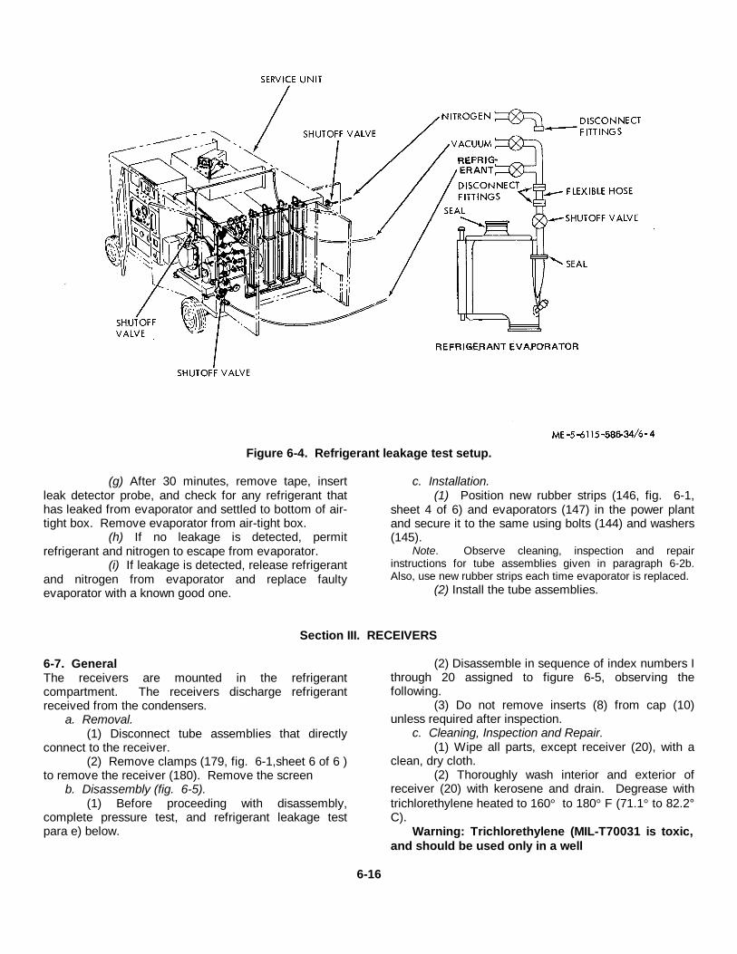
Figure 6-4. Refrigerant leakage test setup.
(g) After 30 minutes, remove tape, insertleak detector probe, and check for any refrigerant thathas leaked from evaporator and settled to bottom of air-tight box. Remove evaporator from air-tight box.
(h) If no leakage is detected, permitrefrigerant and nitrogen to escape from evaporator.
(i) If leakage is detected, release refrigerantand nitrogen from evaporator and replace faultyevaporator with a known good one.
c. Installation.(1) Position new rubber strips (146, fig. 6-1,
sheet 4 of 6) and evaporators (147) in the power plantand secure it to the same using bolts (144) and washers(145).
Note. Observe cleaning, inspection and repairinstructions for tube assemblies given in paragraph 6-2b.Also, use new rubber strips each time evaporator is replaced.
(2) Install the tube assemblies.
Section III. RECEIVERS
6-7. GeneralThe receivers are mounted in the refrigerantcompartment. The receivers discharge refrigerantreceived from the condensers.
a. Removal.(1) Disconnect tube assemblies that directly
connect to the receiver.(2) Remove clamps (179, fig. 6-1,sheet 6 of 6 )
to remove the receiver (180). Remove the screenb. Disassembly (fig. 6-5).
(1) Before proceeding with disassembly,complete pressure test, and refrigerant leakage testpara e) below.
(2) Disassemble in sequence of index numbers Ithrough 20 assigned to figure 6-5, observing thefollowing.
(3) Do not remove inserts (8) from cap (10)unless required after inspection.
c. Cleaning, Inspection and Repair.(1) Wipe all parts, except receiver (20), with a
clean, dry cloth.(2) Thoroughly wash interior and exterior of
receiver (20) with kerosene and drain. Degrease withtrichlorethylene heated to 160° to 180° F (71.1° to 82.2°C).
Warning: Trichlorethylene (MIL-T70031 is toxic,and should be used only in a well
6-16
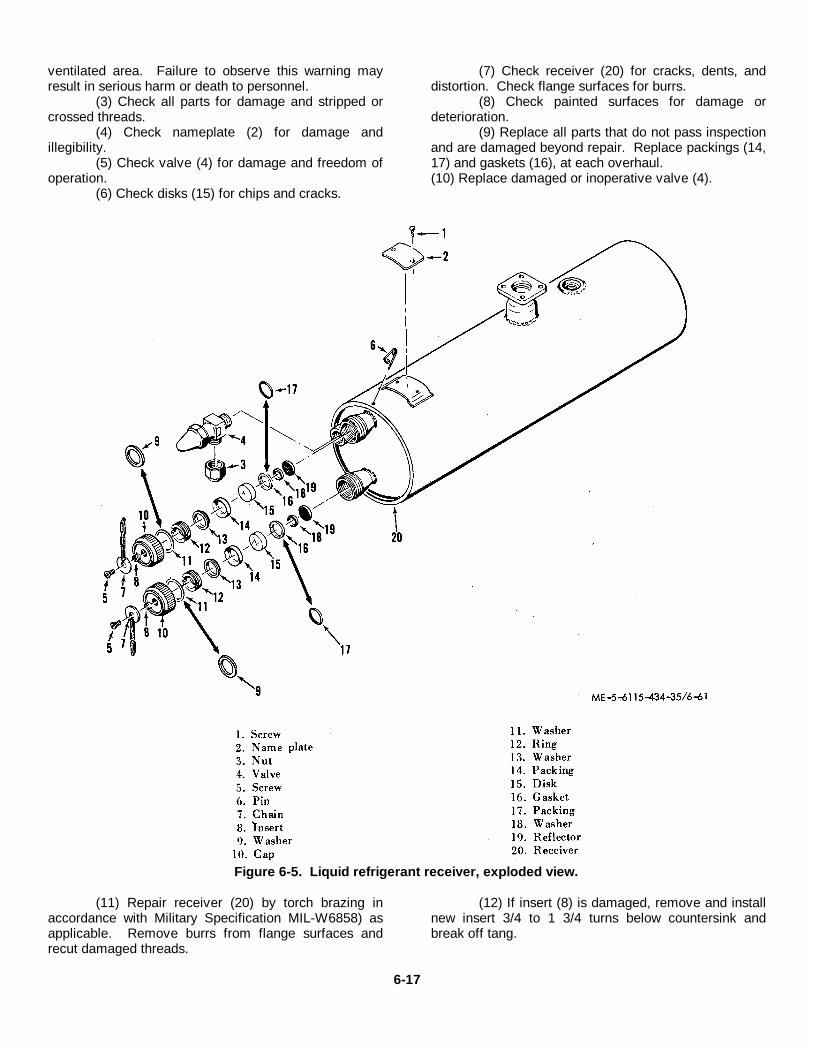
ventilated area. Failure to observe this warning mayresult in serious harm or death to personnel.
(3) Check all parts for damage and stripped orcrossed threads.
(4) Check nameplate (2) for damage andillegibility.
(5) Check valve (4) for damage and freedom ofoperation.
(6) Check disks (15) for chips and cracks.
(7) Check receiver (20) for cracks, dents, anddistortion. Check flange surfaces for burrs.
(8) Check painted surfaces for damage ordeterioration.
(9) Replace all parts that do not pass inspectionand are damaged beyond repair. Replace packings (14,17) and gaskets (16), at each overhaul.(10) Replace damaged or inoperative valve (4).
Figure 6-5. Liquid refrigerant receiver, exploded view.
(11) Repair receiver (20) by torch brazing inaccordance with Military Specification MIL-W6858) asapplicable. Remove burrs from flange surfaces andrecut damaged threads.
(12) If insert (8) is damaged, remove and installnew insert 3/4 to 1 3/4 turns below countersink andbreak off tang.
6-17
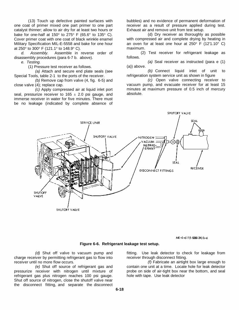
(13) Touch up defective painted surfaces withone coat of primer mixed one part primer to one partcatalyst thinner; allow to air dry for at least two hours orbake for one-half at 150° to 275° F (65.6° to 135° C).Cover primer coat with one coat of black wrinkle enamelMilitary Specification MIL-E-5558 and bake for one hourat 250° to 300° F (121.1° to 148.9° C).
d. Assembly. Assemble in reverse order ofdisassembly procedures (para 6-7 b. above).
e. Testing.(1) Pressure test receiver as follows.
(a) Attach and secure end plate seals (seeSpecial Tools, table 2-1 to the ports of the receiver.
(b) Remove cap from valve (4, fig. 6-5) andclose valve (4); replace cap.
(c) Apply compressed air at liquid inlet portseal, pressurize receiver to 165 ± 2.0 psi gauge, andimmerse receiver in water for five minutes. There mustbe no leakage (indicated by complete absence of
bubbles) and no evidence of permanent deformation ofreceiver as a result of pressure applied during test.Exhaust air and remove unit from test setup.
(d) Dry receiver as thoroughly as possiblewith compressed air and complete drying by heating inan oven for at least one hour at 250° F (12'1.10° C)maximum.
(2) Test receiver for refrigerant leakage asfollows.
(a) Seal receiver as instructed (para e (1)(a)) above.
(b) Connect liquid inlet of unit torefrigeration system service unit as shown in figure
(c) Open valve connecting receiver tovacuum pump, and evacuate receiver for at least 15minutes at maximum pressure of 0.5 inch of mercuryabsolute.
Figure 6-6. Refrigerant leakage test setup.
(d) Shut off valve to vacuum pump andcharge receiver by permitting refrigerant gas to flow intoreceiver until no more flow occurs.
(e) Shut off source of refrigerant gas andpressurize receiver with nitrogen until mixture ofrefrigerant gas plus nitrogen reaches 100 psi gauge.Shut off source of nitrogen, close the shutoff valve nearthe disconnect fitting, and separate the disconnect
fitting. Use leak detector to check for leakage fromreceiver through disconnect fitting.
(f) Fabricate an airtight box large enough tocontain one unit at a time. Locate hole for leak detectorprobe on side of air-tight box near the bottom, and sealhole with tape. Use leak detector
6-18
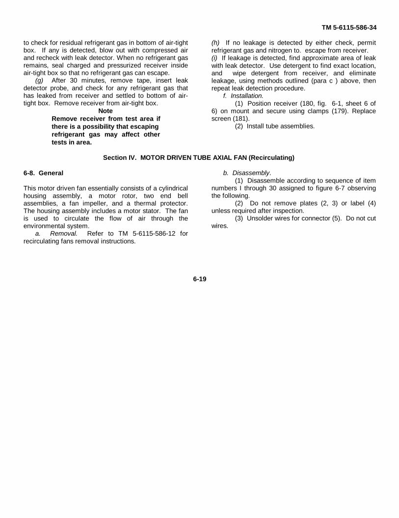
TM 5-6115-586-34
to check for residual refrigerant gas in bottom of air-tightbox. If any is detected, blow out with compressed airand recheck with leak detector. When no refrigerant gasremains, seal charged and pressurized receiver insideair-tight box so that no refrigerant gas can escape.
(g) After 30 minutes, remove tape, insert leakdetector probe, and check for any refrigerant gas thathas leaked from receiver and settled to bottom of air-tight box. Remove receiver from air-tight box.
NoteRemove receiver from test area ifthere is a possibility that escapingrefrigerant gas may affect othertests in area.
(h) If no leakage is detected by either check, permitrefrigerant gas and nitrogen to. escape from receiver.(i) If leakage is detected, find approximate area of leakwith leak detector. Use detergent to find exact location,and wipe detergent from receiver, and eliminateleakage, using methods outlined (para c ) above, thenrepeat leak detection procedure.
f. Installation.(1) Position receiver (180, fig. 6-1, sheet 6 of
6) on mount and secure using clamps (179). Replacescreen (181).
(2) Install tube assemblies.
Section IV. MOTOR DRIVEN TUBE AXIAL FAN (Recirculating)
6-8. General
This motor driven fan essentially consists of a cylindricalhousing assembly, a motor rotor, two end bellassemblies, a fan impeller, and a thermal protector.The housing assembly includes a motor stator. The fanis used to circulate the flow of air through theenvironmental system.
a. Removal. Refer to TM 5-6115-586-12 forrecirculating fans removal instructions.
b. Disassembly.(1) Disassemble according to sequence of item
numbers I through 30 assigned to figure 6-7 observingthe following.
(2) Do not remove plates (2, 3) or label (4)unless required after inspection.
(3) Unsolder wires for connector (5). Do not cutwires.
6-19

Figure 6-7. Tube axial motor driven fan, part no. 605370-1-2, exploded view.
6-20
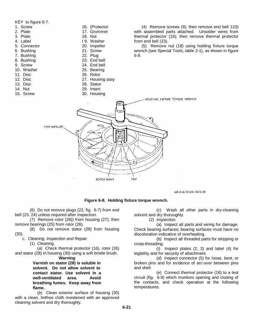
KEY to figure 6-7.1. Screw 16. (Protector2. Plate 17. Grommet3. Plate 18. Nut4. Label I 9. Washer5. Connector 20. Impeller6. Bushing 21. Screw7. Bushing 22. Plug8. Bushing 23. End bell9. Screw 24. End bell10. Washer 25. Bearing11. Disc 26. Rotor12. Disc 27. Housing assy13. Disc 28. Stator14. Nut 29. Insert15. Screw 30. Housing
(4) Remove screws (9); then remove end bell 123)with assembled parts attached. Unsolder wires fromthermal protector (16); then remove thermal protectorfrom end bell (23).
(5) Remove nut (18) using holding fixture torquewrench (see Special Tools, table 2-1), as shown in figure6-8.
Figure 6-8. Holding fixture torque wrench.
(6) Do not remove plugs (22, fig. 6-7) from endbell (23, 24) unless required after inspection.
(7) Remove rotor (26}) from housing (27); thenremove bearings (25) from rotor (26).
(8) Do not remove stator (28) from housing(30).
c. Cleaning, Inspection and Repair.(1) Cleaning.
(a) Check thermal protector (16), rotor (26)and stator (28) in housing (30) using a soft bristle brush.
WarningVarnish on stator (28) is soluble insolvent. Do not allow solvent tocontact stator. Use solvent in awell-ventilated area. Avoidbreathing fumes. Keep away fromflame.
(b) Clean exterior surface of housing (30)with a clean, lintfree cloth moistened with an approvedcleaning solvent and dry thoroughly.
(c) Wash all other parts in dry-cleaningsolvent and dry thoroughly.
(2) Inspection.(a) Inspect all parts and wiring for damage.
Check bearing surfaces; bearing surfaces must have nodiscoloration indicative of overheating.
(b) Inspect all threaded parts for stripping orcross-threading.
(i) Inspect plates (2, 3) and label (4) forlegibility and for security of attachment.
(d) Inspect connector (5) for loose, bent, orbroken pins and for evidence of arc-over between pinsand shell.
(e) Connect thermal protector (16) to a testcircuit (fig. 6-9) which monitors opening and closing ofthe contacts, and check operation at the followingtemperatures.
6-21
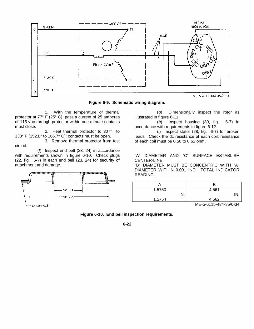
Figure 6-9. Schematic wiring diagram.
1. With the temperature of thermalprotector at 77° F (25° C), pass a current of 25 amperesof 115 vac through protector within one minute contactsmust close.
2. Heat thermal protector to 307° to333° F (152.8° to 166.7° C); contacts must be open.
3. Remove thermal protector from testcircuit.
(f) Inspect end bell (23, 24) in accordancewith requirements shown in figure 6-10. Check plugs(22, fig. 6-7) in each end bell (23, 24) for security ofattachment and damage.
(g) Dimensionally inspect the rotor asillustrated in figure 6-11.
(h) Inspect housing (30, fig. 6-7) inaccordance with requirements in figure 6-12.
(i) Inspect stator (28, fig. 6-7) for brokenleads. Check the dc resistance of each coil; resistanceof each coil must be 0.50 to 0.62 ohm.
"A" DIAMETER AND "C" SURFACE ESTABLISHCENTER-LINE."B" DIAMETER MUST BE CONCENTRIC WITH "A"DIAMETER WITHIN 0.001 INCH TOTAL INDICATORREADING.
A B1.5750 4.561
IN. IN.1.5754 4.562
ME-5-6115-434-35/6-34
Figure 6-10. End bell inspection requirements.
6-22
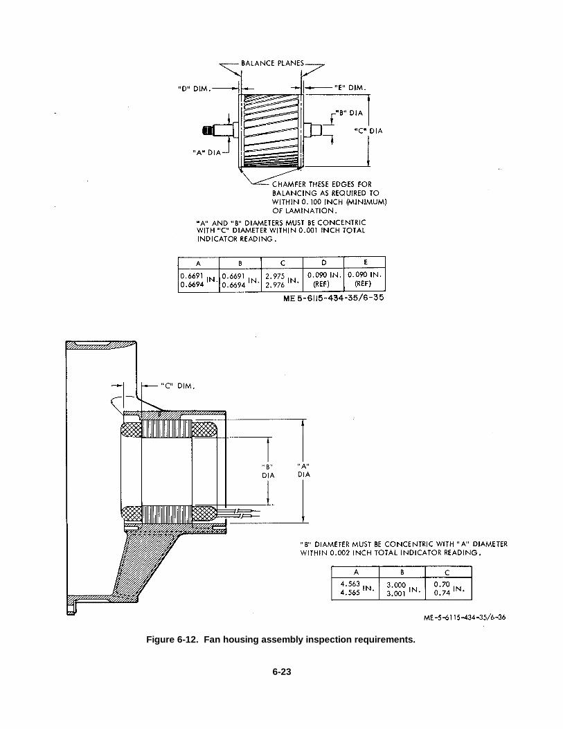
Figure 6-12. Fan housing assembly inspection requirements.
6-23

(j) Inspect blades of impeller (20, fig. 6-7)and outside diameter of hub for nicks, cracks, erosion.Inspect blade tips and interior of housing (27) forevidence of scraping.
(3) Repair.
(a) Replace all parts that do not passinspection requirements and are damaged beyondrepair.
(b) Replace washer (10, fig. 6-7), grommet(17), and bearings (25) regardless of condition. Usebearing press fixture to press bearing (25) onto rotor(26) shaft, as shown in figure 6-13.
Figure 6-13. Bearing installation.(c) Replace rotor if dimensional
requirements are not met.(d) If impeller appears to be damaged or
faulty, replace. Report damaged impeller to depotmaintenance for repair.
(e) If inserts (29) are defective, removedefective insert and install new insert 3/4 to 1 1/2pitches below surface of housing (30). Remove tangs.
d. Assembly.(1) Assemble in reverse order of removal
procedures (para 6-8 b.) observing the following.(2) Install rotor (26) with bearings (25) into
housing assembly (27).(3) Install end bell (24) with plugs (22) and
secure with screws (21). Coat threads of screws with
sealant (Military Specification MIL-S-22473, class 40)and install screws while sealant is wet.
(4) Install impeller (20) on shaft of rotor (26),observing direction of rotation. Apply anti- seizecompound (Federal Specification JAN-A- 669) tothreaded shaft of rotor (26); then install washer (19) andnut (18). Tighten nut (18) to 230 to 270 pound-inchestorque, using holding fixture torque wrench. (fig. 6-8)
(5) Install thermal protector (16, fig. 6-7) onend bell (23). Temporarily install end bell (23) onhousing (27). Measure rotor (26) end play, using endplay measuring fixture (fig. 6-14). Install discs (11, 12,13, fig. 6-7) as required to obtain shaft end play of0.055 to 0.065 inch.
6-24
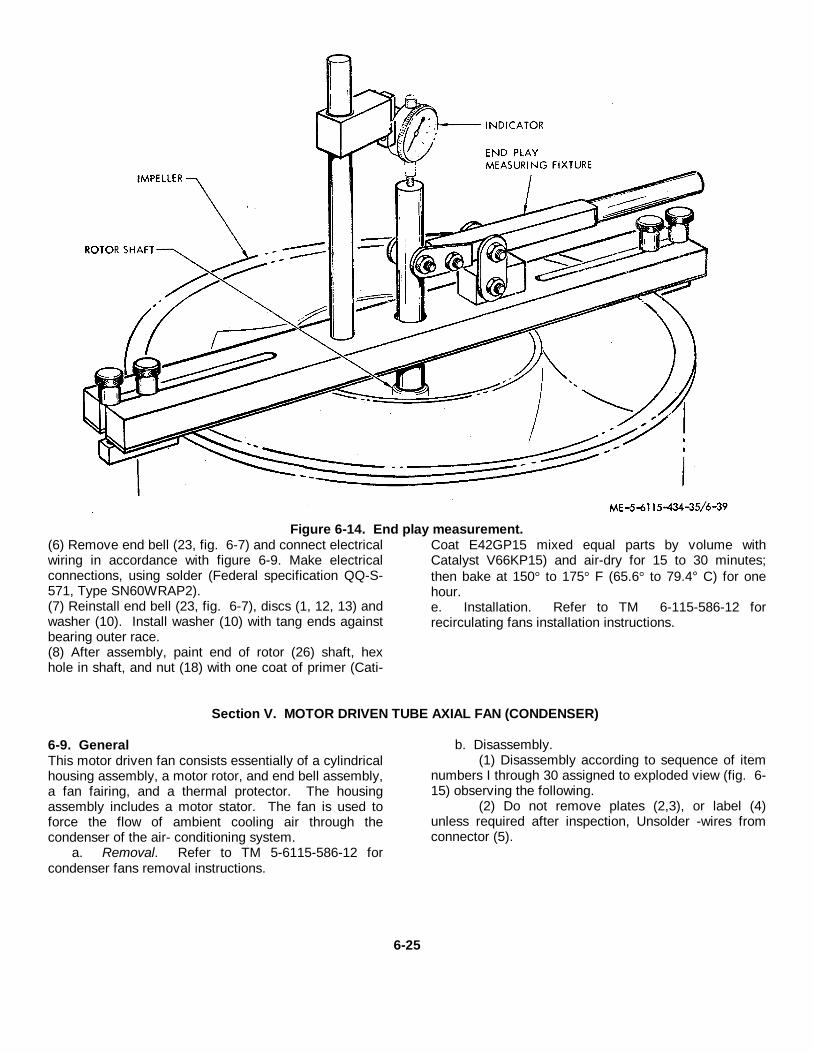
Figure 6-14. End play measurement.(6) Remove end bell (23, fig. 6-7) and connect electricalwiring in accordance with figure 6-9. Make electricalconnections, using solder (Federal specification QQ-S-571, Type SN60WRAP2).(7) Reinstall end bell (23, fig. 6-7), discs (1, 12, 13) andwasher (10). Install washer (10) with tang ends againstbearing outer race.(8) After assembly, paint end of rotor (26) shaft, hexhole in shaft, and nut (18) with one coat of primer (Cati-
Coat E42GP15 mixed equal parts by volume withCatalyst V66KP15) and air-dry for 15 to 30 minutes;then bake at 150° to 175° F (65.6° to 79.4° C) for onehour.e. Installation. Refer to TM 6-115-586-12 forrecirculating fans installation instructions.
Section V. MOTOR DRIVEN TUBE AXIAL FAN (CONDENSER)
6-9. GeneralThis motor driven fan consists essentially of a cylindricalhousing assembly, a motor rotor, and end bell assembly,a fan fairing, and a thermal protector. The housingassembly includes a motor stator. The fan is used toforce the flow of ambient cooling air through thecondenser of the air- conditioning system.
a. Removal. Refer to TM 5-6115-586-12 forcondenser fans removal instructions.
b. Disassembly.(1) Disassembly according to sequence of item
numbers I through 30 assigned to exploded view (fig. 6-15) observing the following.
(2) Do not remove plates (2,3), or label (4)unless required after inspection, Unsolder -wires fromconnector (5).
6-25

Figure 6-15. Tube axial motor driven fan, exploded view.
6-26
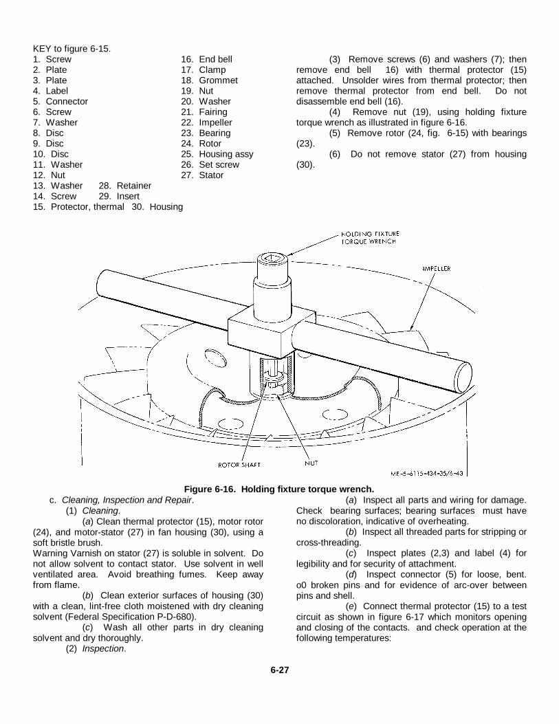
KEY to figure 6-15.1. Screw 16. End bell2. Plate 17. Clamp3. Plate 18. Grommet4. Label 19. Nut5. Connector 20. Washer6. Screw 21. Fairing7. Washer 22. Impeller8. Disc 23. Bearing9. Disc 24. Rotor10. Disc 25. Housing assy11. Washer 26. Set screw12. Nut 27. Stator13. Washer 28. Retainer14. Screw 29. Insert15. Protector, thermal 30. Housing
(3) Remove screws (6) and washers (7); thenremove end bell 16) with thermal protector (15)attached. Unsolder wires from thermal protector; thenremove thermal protector from end bell. Do notdisassemble end bell (16).
(4) Remove nut (19), using holding fixturetorque wrench as illustrated in figure 6-16.
(5) Remove rotor (24, fig. 6-15) with bearings(23).
(6) Do not remove stator (27) from housing(30).
Figure 6-16. Holding fixture torque wrench.c. Cleaning, Inspection and Repair.
(1) Cleaning.(a) Clean thermal protector (15), motor rotor
(24), and motor-stator (27) in fan housing (30), using asoft bristle brush.Warning Varnish on stator (27) is soluble in solvent. Donot allow solvent to contact stator. Use solvent in wellventilated area. Avoid breathing fumes. Keep awayfrom flame.
(b) Clean exterior surfaces of housing (30)with a clean, lint-free cloth moistened with dry cleaningsolvent (Federal Specification P-D-680).
(c) Wash all other parts in dry cleaningsolvent and dry thoroughly.
(2) Inspection.
(a) Inspect all parts and wiring for damage.Check bearing surfaces; bearing surfaces must haveno discoloration, indicative of overheating.
(b) Inspect all threaded parts for stripping orcross-threading.
(c) Inspect plates (2,3) and label (4) forlegibility and for security of attachment.
(d) Inspect connector (5) for loose, bent.o0 broken pins and for evidence of arc-over betweenpins and shell.
(e) Connect thermal protector (15) to a testcircuit as shown in figure 6-17 which monitors openingand closing of the contacts. and check operation at thefollowing temperatures:
6-27
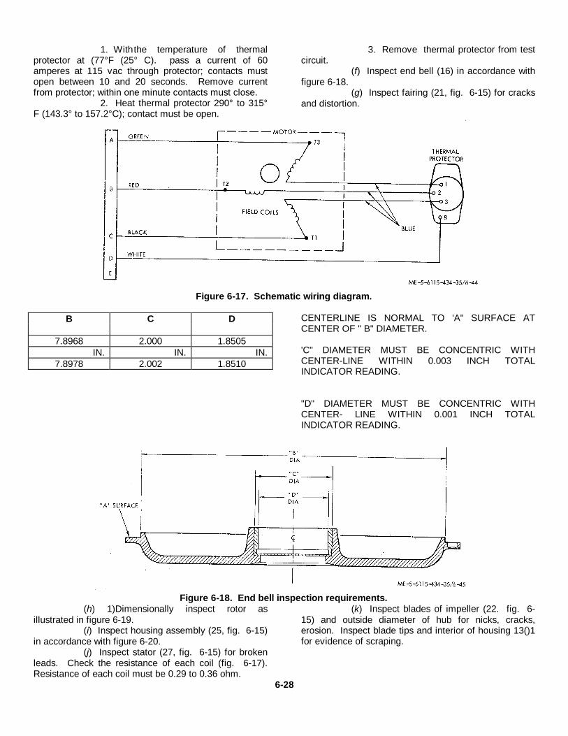
1. Withthe temperature of thermalprotector at (77°F (25° C). pass a current of 60amperes at 115 vac through protector; contacts mustopen between 10 and 20 seconds. Remove currentfrom protector; within one minute contacts must close.
2. Heat thermal protector 290° to 315°F (143.3° to 157.2°C); contact must be open.
3. Remove thermal protector from testcircuit.
(f) Inspect end bell (16) in accordance withfigure 6-18.
(g) Inspect fairing (21, fig. 6-15) for cracksand distortion.
Figure 6-17. Schematic wiring diagram.
B C D
7.8968 2.000 1.8505IN. IN. IN.
7.8978 2.002 1.8510
CENTERLINE IS NORMAL TO 'A" SURFACE ATCENTER OF " B" DIAMETER.
'C" DIAMETER MUST BE CONCENTRIC WITHCENTER-LINE WITHIN 0.003 INCH TOTALINDICATOR READING.
"D" DIAMETER MUST BE CONCENTRIC WITHCENTER- LINE WITHIN 0.001 INCH TOTALINDICATOR READING.
Figure 6-18. End bell inspection requirements.(h) 1)Dimensionally inspect rotor as
illustrated in figure 6-19.(i) Inspect housing assembly (25, fig. 6-15)
in accordance with figure 6-20.(j) Inspect stator (27, fig. 6-15) for broken
leads. Check the resistance of each coil (fig. 6-17).Resistance of each coil must be 0.29 to 0.36 ohm.
(k) Inspect blades of impeller (22. fig. 6-15) and outside diameter of hub for nicks, cracks,erosion. Inspect blade tips and interior of housing 13()1for evidence of scraping.
6-28
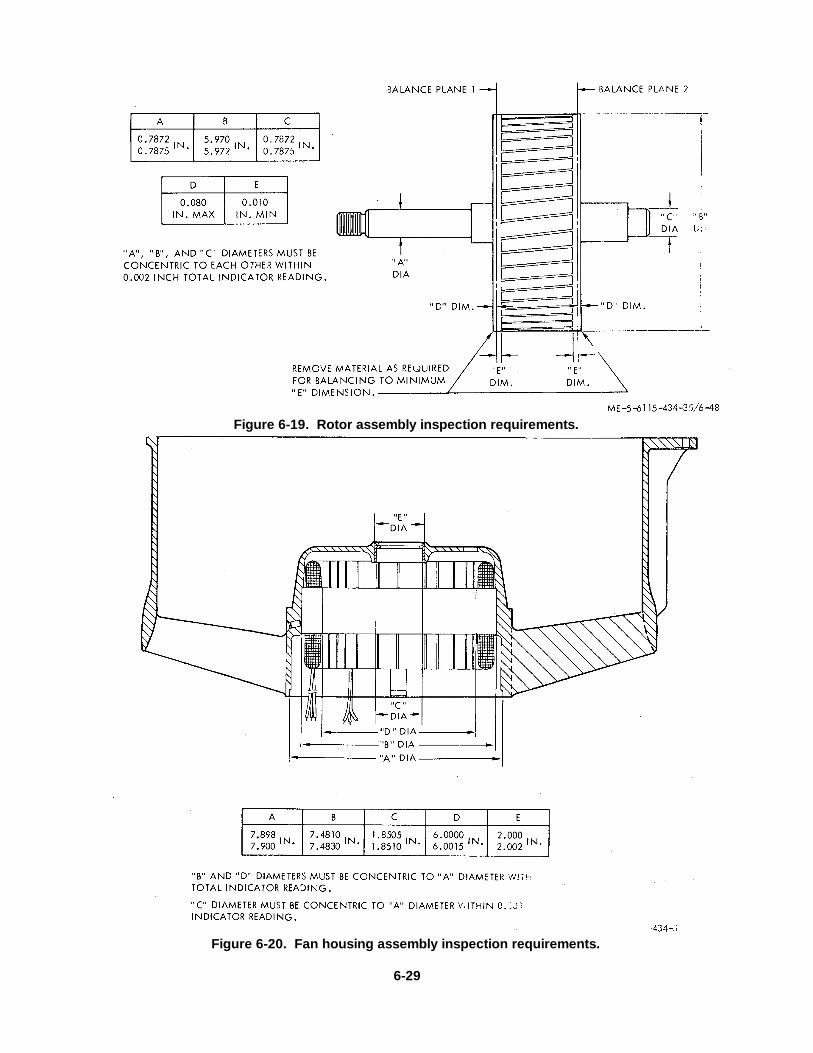
Figure 6-19. Rotor assembly inspection requirements.
Figure 6-20. Fan housing assembly inspection requirements.
6-29
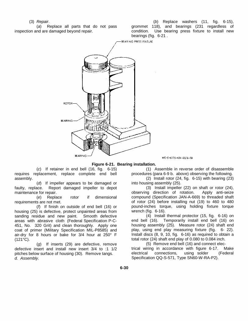
(3) Repair.(a) Replace all parts that do not pass
inspection and are damaged beyond repair.
(b) Replace washers (11, fig. 6-15),grommet 118), and bearings (231 regardless ofcondition. Use bearing press fixture to install newbearings (fig. 6-21 .
Figure 6-21. Bearing installation.(c) If retainer in end bell (16, fig. 6-15)
requires replacement, replace complete end bellassembly.
(d) If impeller appears to be damaged orfaulty, replace. Report damaged impeller to depotmaintenance for repair.
(e) Replace rotor if dimensionalrequirements are not met.
(f) If finish on outside of end bell (16) orhousing (25) is defective, protect unpainted areas fromsanding residue and new paint. Smooth defectiveareas with abrasive cloth (Federal Specification P-C-451, No. 320 Grit) and clean thoroughly. Apply onecoat of primer (Military Specification MIL-P8585) andair-dry for 8 hours or bake for 3/4 hour at 250° F(121°C).
(g) If inserts (29) are defective, removedefective insert and install new insert 3/4 to :1 1/2pitches below surface of housing (30). Remove tangs.d. Assembly.
(1) Assemble in reverse order of disassembleprocedures (para 6-9 b. above) observing the following.
(2) Install rotor (24, fig. 6-15) with bearing (23)into housing assembly (25).
(3) Install impeller (22) on shaft or rotor (24),observing direction of rotation. Apply anti-seizecompound (Specification JAN-A-669) to threaded shaftof rotor (24) before installing nut (19) to 460 to 480pound-inches torque, using holding fixture torquewrench (fig. 6-16).
(4) Install thermal protector (15, fig. 6-16) onend bell (16). Temporarily install end bell (16) onhousing assembly (25). Measure rotor (24) shaft endplay, using end play measuring fixture (fig. 6- 22).Install discs (8, 9, 10, fig. 6-16) as required to obtain atotal rotor (24) shaft end play of 0.080 to 0.084 inch.
(5) Remove end bell (16) and connect elec-trical wiring in accordance with figure 6-17. Makeelectrical connections, using solder (FederalSpecification QQ-S-571, Type SN60-W-RA-P2).
6-30
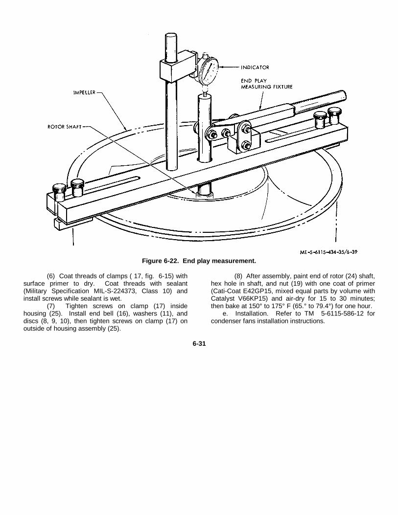
Figure 6-22. End play measurement.
(6) Coat threads of clamps ( 17, fig. 6-15) withsurface primer to dry. Coat threads with sealant(Military Specification MIL-S-224373, Class 10) andinstall screws while sealant is wet.
(7) Tighten screws on clamp (17) insidehousing (25). Install end bell (16), washers (11), anddiscs (8, 9, 10), then tighten screws on clamp (17) onoutside of housing assembly (25).
(8) After assembly, paint end of rotor (24) shaft,hex hole in shaft, and nut (19) with one coat of primer(Cati-Coat E42GP15, mixed equal parts by volume withCatalyst V66KP15) and air-dry for 15 to 30 minutes;then bake at 150° to 175° F (65.° to 79.4°) for one hour.
e. Installation. Refer to TM 5-6115-586-12 forcondenser fans installation instructions.
6-31
CHAPTER 7
REPAIR OF BLEED AIR AND EXHAUST HEATING INSTALLATION
7-1. GeneralThe bleed air and exhaust heating installation suppliesheated air upon user demand. The installation consistsof an engine mounted unloading air shutoff valve,ducting, two hot air flow control valves, temperaturesensors and controls mounted on the air conditioningcontrol panels. The exhaust system portion of thisinstallation consists of a diffuser, bellows, box, plenumand stack assembly. A heat exchanger, mounted on thebox next to the stack, is also included in this installation.Tubing hoses and plumbing fittings provideinterconnection of these components and connection tothe power plant.7-2. Ducting, Tubing, and Plumbing Fittings
a. General. The ducting, tube assemblies andplumbing fittings interconnect the heating systemcomponents.
b. Removal. Remove ducting, tube and plumbingfittings only as required and feasible by following thesequence of index numbers, 1 through 30, assigned tofigure 7-1, sheet I of 3.
c. Cleaning, Repair and Inspection.(1) Clean ducting, tubes and plumbing fittings
with an approved solvent and thoroughly dry with filteredcompressed air.
(2) Visually inspect ducting for dents, cracks,damage to mating flanges or other damage.
(3) Inspect tubes for cracks, dents. damagedthreads or other damage.
(4) Replace all parts damaged beyond simplerepair.
d. Installation. Install ducting, tube assemblies andplumbing fittings in reverse order of removalprocedures.
7-1
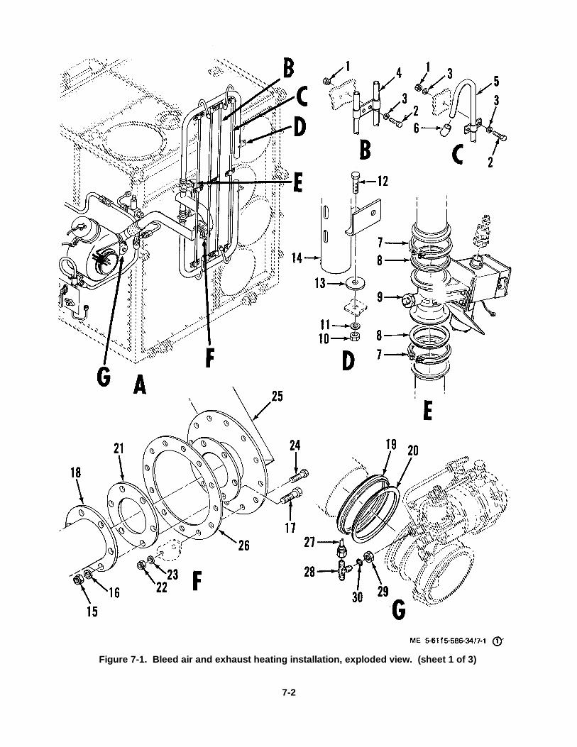
Figure 7-1. Bleed air and exhaust heating installation, exploded view. (sheet 1 of 3)
7-2

KEY to fig. 7-1. 8. Metal gasket 16. Plain washer1. Nut 9. Butterfly valve 17. Bolt 24. Bolt2. Bolt 10. Nut 18. Flexible pipe 25. Heat manifold duct3. Flat washer 11. Flat washer 19. Coupling-clamp 26. Gasket4. Shielding support 12. Bolt 20. Gasket 27. Tube assembly5. Shielding tube 13. Washer 21. Gasket 28. Tee6. Sleeving 14. Metal tube 22. Nut 29. Nut7. Coupling-clamp 15. Nut 23. Plain washer 30. Packing
7-3
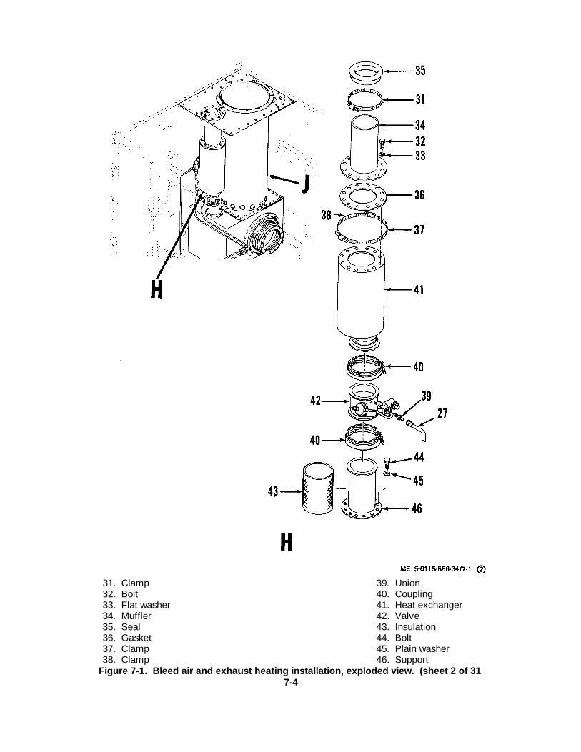
31. Clamp 39. Union32. Bolt 40. Coupling33. Flat washer 41. Heat exchanger34. Muffler 42. Valve35. Seal 43. Insulation36. Gasket 44. Bolt37. Clamp 45. Plain washer38. Clamp 46. Support
Figure 7-1. Bleed air and exhaust heating installation, exploded view. (sheet 2 of 317-4

7-5

Figure 7-1. Bleed air and exhaust heating installation, exploded view. (sheet 3 of 3)
7-6
KEY to figure 7-1--Continued: 66. Flat washer47. Gasket 67. Skin48. Gasket 68. Gasket49. Gasket 69. Channel50. Clamp 70. Bolt51. Seal 71. Flat washer52. Bolt 72. Flange53. Washer :73. Gasket54. Washer 74. Flange55. Exhaust stack .75. Plenum56. Gasket 76. Insulation57 . Gasket 77. Insulation58. Gasket 78. Frame59. Tube assembly 79. Coupling clamp60. Union 80. Gasket61. Nut 81. Bolt62. Flat washer 82. Flat washer63. Bolt 83. Bellows64. Spacer 84. Gasket65. Bolt 85. Diffuser7-3. Heat Exchanger
a. Removal.(1) Remove clamp (31, fig. 7-1, sheet 2 of 3),
bolts (32), and washers (33), then remove muffler (341,seal (35) and gasket (36) from exchanger (41).
(2) Loosen and remove clamp (37, 38), uppercoupling (40) and exchanger (41) from outlet flangeof valve (42). Remove tube (27) from union (3:9 1.
(3) Remove lower coupling (40), and valve(42).
(4) Remove insulation (43) from around support(46), then remove bolts (44) and washers (45) securingsupport (46). Remove support (46) and gaskets (47, 48,49, fig. 7-1, sheet 3 of 3) from exhaust box.
(5) Discard gaskets (47, 48, 49, 36) and seal(35) at each overhaul.
b. Cleaning, Inspection and Repair.(1) Clean all parts with a rag moistened in an
approved cleaning solvent.(2) Inspect parts for cracks, dents or other
obvious damage.(3) Inspect all threaded parts for stripped,
crossed, or peened threads.(4) Repair minor cracks and dents using
simple shop repair practices.(5) Replace all parts damaged beyond simple
repair.(6) Replace gaskets and seals at each
overhaul.c. Installation.
(1) Install insulation (43, fig. 7-1, sheet 2 of 3),around support (46). Install gasket (47 through 49) ontoexhaust box, then install support (46) with insulation (43)onto gaskets (47 through 49) and secure with washers(45) and bolts (44).
(2) Install valve (42) onto support (46) andsecure with one coupling (40).
(3) Install exchanger (41) onto valve (42) and
secure with coupling (40) and clamps (37 and 38).(4) Position gasket (36) onto exchanger (41),
position seal (35) and slide exhaust (34) in on top ofexchanger (41 ) with gasket (36) and secure withwashers (33) and bolts (32), secure (35) to exhaust 134)with clamp (31).
(5) Install plumbing connections.7-4. Exhaust SystemThe exhaust system consists of a ring assemblymounted to the enclosure, exhaust box, and a bellowsand diffuser interconnecting the engine exhaust to theexhaust box.
a. Disassembly.(1) Loosen and remove clamp (50, fig. 7-1, sheet 3 of3), remove bolts (52), washers (53, 54) from exhauststack (55).
(2) Remove exhaust stack (55) from top ofplenum (75), then remove gaskets (56, 57, 58) from topof frame (78) and seal (51) from top of exhaust stack(55).
(3) Remove tube assembly (59) from union (60)on bottom of frame (78).
(4) Remove water system heat ducting from topof frame (78).
(5) Remove coupling clamp (79), gasket (80),bolts (70), washers (71), flange (72) and gasket (73)from frame (78) inlet.
(6) Remove bellows (83), gaskets (73) andflange (74) from frame (78).
(7) Remove bolts (81), washers (82), anddiffuser (85) with gasket (84) from frame (78).
(8) Remove bolts (65), washers (66), skin (67),gasket (68) and channel (69) from frame ( 78).
(9) Lift plenum (75) from frame (78), thenremove insulation (76, 77). Remove nuts (61), washers(62), bolts (63), and frame (78), then remove spacers(64).
b. Cleaning, Inspection and Repair.(1) Clean exhaust system components with an
approved solvent and stiff bristled brush.(2) Inspect components for cracks, broken
welds or other damage.(3) Replace any part damaged beyond simple
repair.(4) Replace gaskets (56, 57, 58, 68, 73), and
seal (51) at each overhaul regardless of condition.c. Assembly.
(1) Wrap plenum (75,fig. 7-1,sheet 3 of 3) ininsulation (77).
(2) Fill void between plenum (75) and frame(78) with insulation (76).
(3) Install spacers (64), frame (78), and securewith bolts (63), washers (62) and nuts (61).
(4) Install channel (69), gasket (68) and skin(67). Secure with washers (66) and bolts (65).
(5) Install gasket (84) and diffuser (85) andsecure to bellows (83) with washers (82) and bolts (81).
7-7
(6) Position gaskets (73), flange (74) and flange(7-2); secure with bolts (70) and washers
(7) Install gasket (80) and coupling clamp 179)onto diffuser (85).
(8) Install tube assembly (59) onto union (60).then install new seal (51) to top of exhaust stack (55),and position gasket (56, 57, 58) on top of frame (78).
(9) Install exhaust stack (55) on top ofpreviously installed gasket (56, 57, 58) on top of frame(78) and secure with bolts (52), washers (53, 54).
(10) Install clamp (50) over seal (51) and secureclamp (50).7-5. Bleed Air Lines and Fittings
a. Removal. Refer to TM 5-6115-586-12 forremoval procedures.
b. Cleaning, Inspection and Repair.(1) Clean all parts with an approved cleaning
solvent and dry thoroughly with filtered com- pressedair.
(2) Inspect tube assemblies for kinks, bends,cracks or other damage which might restrict flow orresult in leakage. Inspect nuts and sleeves on tubeassemblies for loose sleeves or. damage to nuts.
(3) Install handles on manual valves andoperate valve to ensure freedom of moving parts andabsence of binding.
(4) Repair minor damage to tube assembliesusing simple shop repair practices. If tube assembliesare damaged beyond simple repair practices, replacethe damaged assembly.
(5) Repair any minor damage to manual valvesusing simple shop repair. Replace frozen, damaged orotherwise inoperative valves.
c. Installation. Refer to TM 5-6115-586-12 forinstallation procedures.
7-8
CHAPTER 8
REPAIR OF WATER SYSTEM PLUMBING INSTALLATION
Section I. TUBE ASSEMBLIES, FITTINGS, AND MANUAL VALVES
8-1. GeneralThis section contains repair instructions for the tubeassemblies and fittings that interconnect water systemcomponents and for the manually operated valvesutilized to control water flow and vent the system.8-2. Removal and DisassemblyRefer to TM 5-6115-586-12 for instructions regardingremoval of tube assemblies, fittings, and valves.8-3. Cleaning, Inspection and Repair
a. Cleaning. Clean tube assemblies, fittings andvalves with soft bristle brush and hot, soapy water.Rinse thoroughly and dry with filtered, compressed air.
NoteDo not use solvent for cleaning asplumbing must carry potablewater. If necessary, the ends oftube assemblies may be sealedand the external surfaces cleanedwith a rag moistened with solvent.
b. Inspection.(1) Inspect fittings for stripped, crossed or
peened threads. Inspect plumbing fittings for cracks orclogged passages.
(2) Inspect tube assemblies for cracks, bendsor crimps which might restrict flow or result in leakage.Inspect connection nuts and sleeves on tube assembliesfor loose sleeves or damage to nuts.
(3) Inspect check valves for crossed, strippedor peened threads.
(4) Inspect hot and cold water shutoff valves,hot water return / drain valve, and hot water tank ventvalve for crossed, stripped, or peened threads or othervisible damage. Check valves for ease of operation andabsence of binding.
c. Repair.(1) Replace all fittings damaged beyond
simple repair of threads.(2) Replace defective tube assemblies.(3) Replace check valves if they do not operate
properly or if threads are damaged beyond simplerepair.
(4) Replace leaking or binding valves andvalves with damaged threads.8-4. Reassembly and InstallationRefer to TM 5-6115-586-12 for instructions oninstallation of tube assemblies, fittings, and valves.
Section II. SURGE TANK AND PRESSURE SWITCH
8-5. GeneralThe surge tank dampens pressure surges in the watersystem. It is mounted to a bracket in the water systemcompartment by two clamps. The pressure switch,mounted to fittings at the top of the tank, actuates thehot water pump contactor (K 15).8-6. RemovalRefer to TM 5-6115-586-12 for removal instructions.8-7. Cleaning, Inspection and Repair
a. Cleaning.Note
Cap openings prior to cleaningtank externally with solvent. Donot get solvent inside tank.
(1) Clean external portions of the tank using anapproved solvent and a stiff bristled brush.
(2) Back flush tank with clean hot water.b. Inspection and Testing.
(1) Inspect threaded areas for crossed,stripped or peened threads.
(2) Inspect tank for cracks, breaks in welds anddents. Tank shall not leak when tested at 150 PSIGminimum.
(3) Inspect switch body for dents, cracks, orother damage.
(4) Check continuity across switch terminalposts. Contact arrangement is single pole, doublethrow: common to one post should be open andcommon to the other post should be closed.
(5) Apply adjustable pressure to pick up area ofswitch and check that the closed set of contacts openand the open set closes at 10-1 PSIG. Contacts shouldreturn to normal positions at 5 PSI differential ondecreasing pressure.
c. Repair.(1) Repair damaged threads. If threads cannot
be repaired, replace the part.
8-1
(2) Welding repair of corrosion resistant steelsurge tank shall be attempted only by properly certifiedwelder. (Refer to MIL-T-5021, Class A, Group II).
(3) Replace pressure switch found to bedefective through inspection or testing.8-8. InstallationRefer to TM 5-6115-586-12 for installation instructions.
Section III. HOT WATER TANK, THERMOSTATIC SWITCH AND RELIEF VALVES
8-9. GeneralThis section contains repair instructions for the hot waterstorage tank, the thermostatic switch and the reliefvalve, mounted to the hot water tank fittings, and thesafety relief valve mounted to the heat exchangerfittings.8-10. Removal of ComponentsRefer to TM 5-6115-586-12 for instructions on removalof the hot water tank, thermostatic switch and reliefvalve.8-11. Hot Water Tank
a. Cleaning and Inspection.Note
Cap all ports on tank. Do notallow solvent to get into tank.
(1) Clean tank externally using an approvedcleaning solvent and a stiff bristled brush.
(2) Clean tank internally by back flushing withclean hot water.
(3) Inspect threaded areas for crossed,stripped or peened, threads.
(4) Inspect tank for cracks, dents or other damage.
b. Repair.(1) Repair defective threads. If threads
cannot be repaired, replace the tank.(2) Welding repair of the hot water tank shall be
attempted only by a certified welder (per MIL-T-5021,Class A, Group II).8-12. Thermostatic Switch
a. Clean thermostatic switch with a cloth dampenedin an approved solvent.
b. Inspect threaded areas for crossed, stripped orpeened threads.
c. Inspect switch body for dents, cracks or otherdamage.
d. Check continuity across terminal posts; circuitshall be closed.
e. Apply heated water to pick up area of switch; asheat reaches 160° ± 4-5°F, circuit across terminal postsshall open.
f. Replace switch if damaged beyond simple repairor if switch fails to meet test requirements.8-13. Pressure and Temperature Relief Valve
a. Clean relief valve using a cloth dampened in anapproved solvent.
b. Inspect threaded areas for crossed, stripped orpeened threads.
c. Provide a means of controlling and measuringpressure and temperature of test water.
d. Inspect relief valve for dents, cracks or otherdamage.
i. Check relief valve setting; valve shall open at 15psig.
f. Check temperature relief setting; valve shall startto open at 200°F and shall be fully open at 210°F.
g. Replace relief valve if damaged beyond simplerepair or if inspection requirements are not met.8-14. Safety Relief Valve
a. Clean safety relief valve using a cloth dampenedin an approved solvent.
b. Inspect threaded areas for stripped, crossed orpeened threads.
c. Inspect body of valve for dents, cracks or otherdamage.
d. Apply air pressure to inlet post of valve andgradually increase pressure to 100 psig. Valve shallrelieve at 100 ± 5 psig.
e. Replace valve if damaged beyond simple repairor if test requirements are not met.8-15. Installation of ComponentsRefer to TM 5-6115-586-12 for installation instructions.
8-2
CHAPTER 9
ENCLOSURE AND SHELL ASSEMBLY
9-1. GeneralThe enclosure and shell assembly contains theoperating components of the power units and systemsand mounts lifting and leveling components.9-2. Enclosure and Shell Assembly
a. Disassembly.(1) Do not disassemble the enclosure unless
inspection reveals damage. If required, disassemble theenclosure assembly by following the sequence of indexnumbers 1 through 271 assigned to figure 9-1 .
(2) Do not disassemble the shell assemblyunless inspection reveals damage. If required,disassemble the shell assembly by following thesequence of index numbers 1 through 315 assigned tofigure 9-1.
NoteDo not disassemble the enclosureor the shell assembly in theirentirety. Remove and
disassemble only those partsrequiring repair or replacementand those parts necessary to gainaccess to the damaged parts.
b. Cleaning. Inspection an Repairs.(1) Clean components of the enclosure with a
clean cloth dampened in an approved solvent, drythoroughly with compressed air.
(2) Inspect doors and panels for cracks, looserivets, damaged fasteners and other defects.
(3) Inspect frame assembly and other weldedcomponents for cracks or breaks on welded joints.Reweld the frame which is aluminum alloy 6061. T4and T6 QQ-A-200 / 8 and QQ-A-250 / 16 using filler4043, examine and certify according to militaryspecification MIL-T-5021.
(4) Repair damaged components using simpleshop repair.
9-1
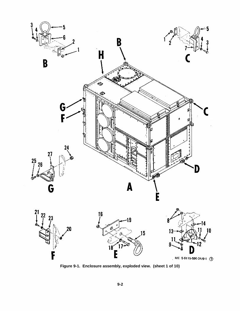
Figure 9-1. Enclosure assembly, exploded view. (sheet 1 of 10)
9-2

KEY to figure 9-1. 7. Bracket 14. Spacer 21. Bolt1. Nut 8. Nut 15. Ring bolt 22. Flat washer2. Plate 9. Bolt 16. Nut 23. Bracket3. Bolt 10. Bolt 17. Bolt 24. Nut4. Flat washer 11. Flat washer 18. Flat washer 25. Bolt5. Ring bolt 12. Bracket 19. Nut plate 26. Flat washer6. Bracket 13. Spacer 20. Nut 27. Folding step
9-3
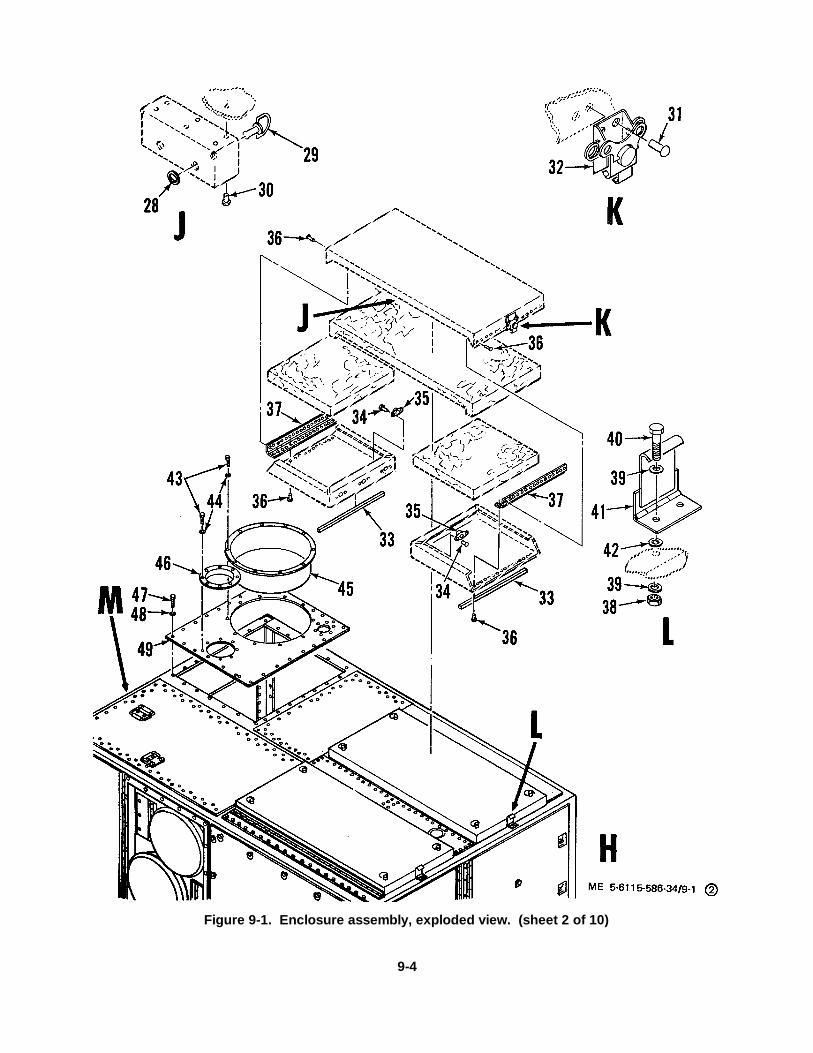
Figure 9-1. Enclosure assembly, exploded view. (sheet 2 of 10)
9-4

KEY to figure 9-1- 32. Catch 38. Nut 44. Flat washerContinued: 33. Tape 39. Flat washer 45. Seal ring28. Retainer 34. Rivet 40. Bolt 46. Ring29. Stud 35. Receptacle 41. Strike 47. Bolt30. Rivet 36. Rivet 42. Flat washer 48. Flat washer31. Rivet 37. Hinge 43. Bolt 49. Top plate
9-5

50. Bolt 62. Turnlock fastener stud 73. Turnlock fastener stud51. Flat washer 63. Rivet 74. Turnlock fastener stud52. Rivet 64. Receptacle 75. Rivet53, Rivet 65. Rivet 76. Rivet54. Hinge 66. Nut plate 77. Hinge55. Retainer 67. Insulation 78. Coupling clamp56. Turnlock fastener stud 68. Bolt 79. Packing57. Turnlock fastener stud 69. Bolt 80. Dust cover58. Rivet 70. Washer 81. Bolt59. Rivet 71. Retainer 82. Flat washer60, Hinge 72. Turnlock fastener stud 83. Screen61. Retainer 84. Air duct
Figure 9-1. Enclosure assembly, exploded view. (sheet 3 of 10)9-6

9-7
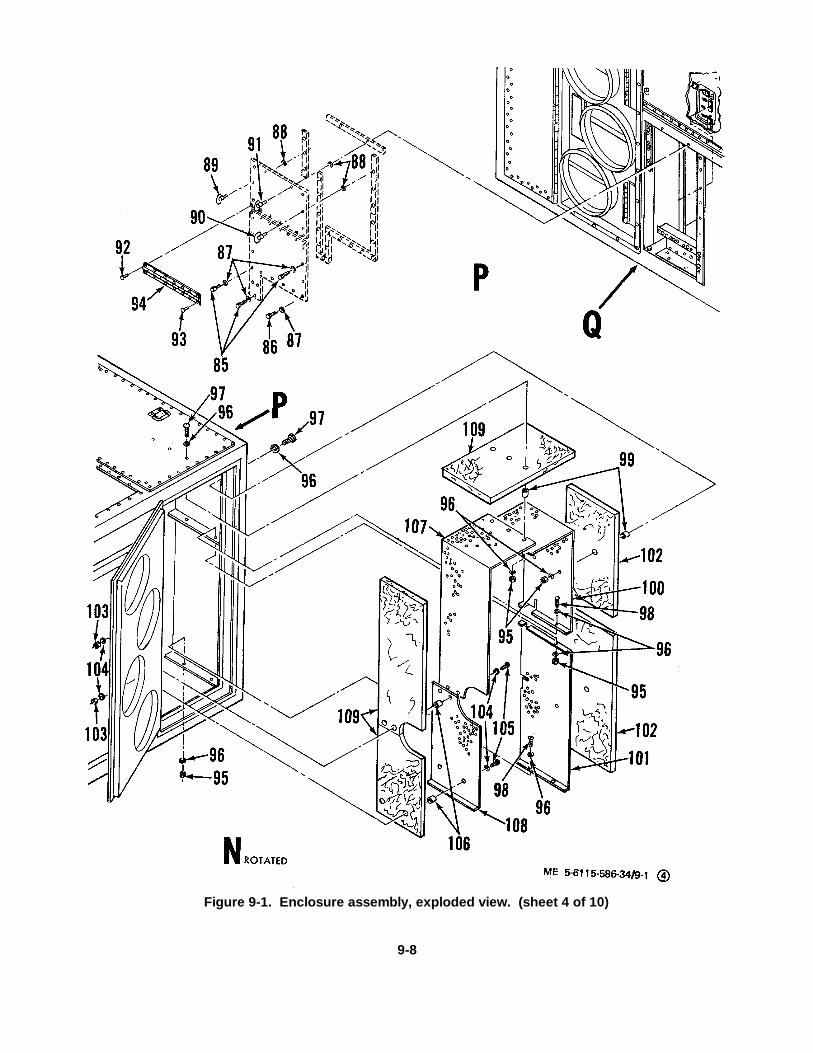
Figure 9-1. Enclosure assembly, exploded view. (sheet 4 of 10)
9-8

KEY to figure 9-1-Continued: 91. Turnlock fastener stud 97. Machine screw 103. Nut85. Bolt 92. Rivet 98. Machine screw 104. Flat washer86. Bolt 93. Rivet 99. Spacer 105. Machine screw87. Flat washer 94. Hinge 100. Shield 106. Spacer88. Retainer 95. Nut 101. Outlet shield 107. Shield89. Turnlock fastener stud 96. Flat washer 102. Insulation 108. Shield90. Turnlock fastener stud 109. Insulation
9-9
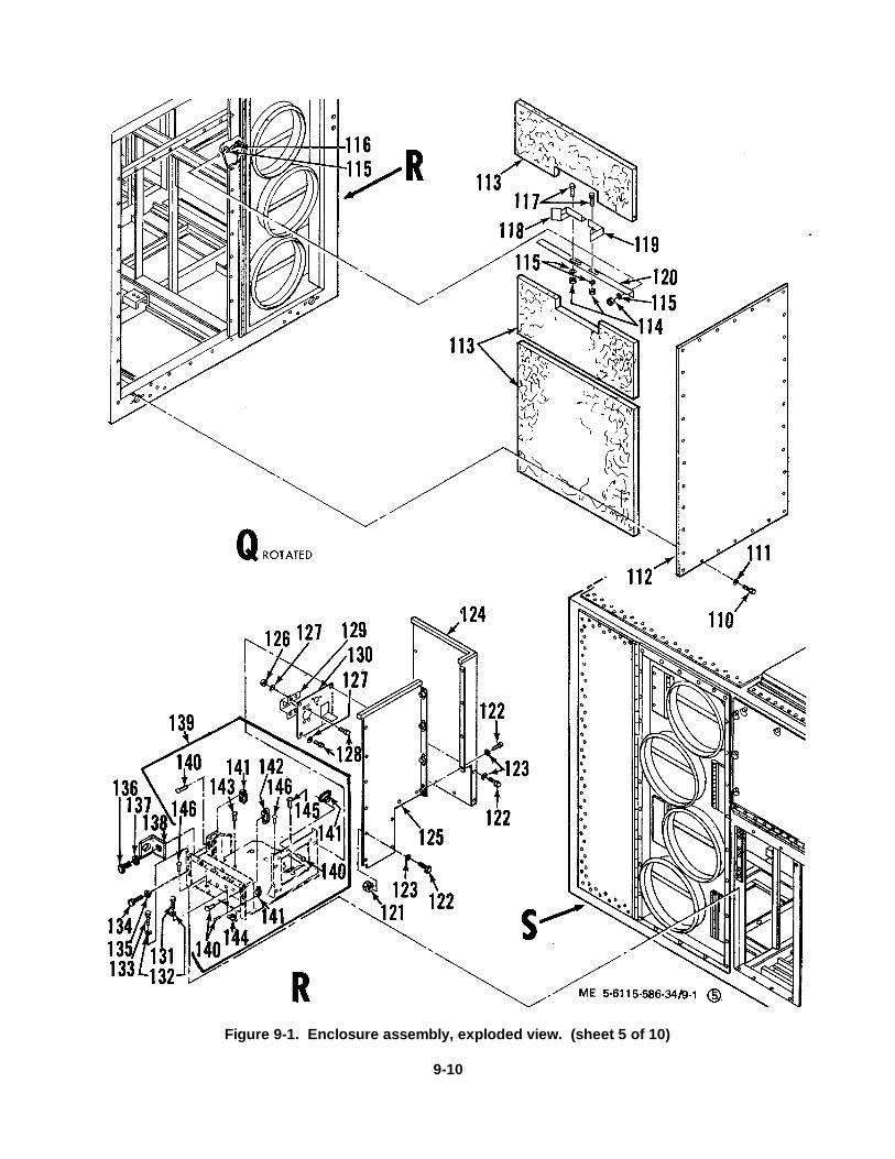
Figure 9-1. Enclosure assembly, exploded view. (sheet 5 of 10)
9-10

KEY to figure 9-1-Continued: 118. Bracket 128. Bolt 138. Clip110. Bolt 119. Bracket 129. Bracket 139. Base plate111. Flat washer 120. Brace 130. Pump mount bracket 140. Rivet112. Panel 121. Nut 131. Bolt 141. Plate nut113. Insulation 122. Bolt 132. Flat washer 142. Plate nut114. Nut' 123. Flat washer 133. Bolt 143. Rivet115. Flat washer 124. Partition 134. Bolt 144. Plate nut116. Bolt 125. Panel 135. Flat washer 145. Rivet117. Bolt 126. Nut 136. Bolt 146. Rivet
127. Flat washer 137. Flat washer
9-11
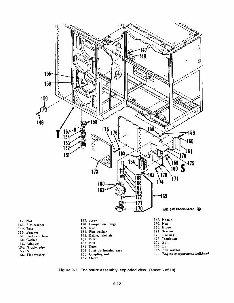
Figure 9-1. Enclosure assembly, exploded view. (sheet 6 of 10)
9-12
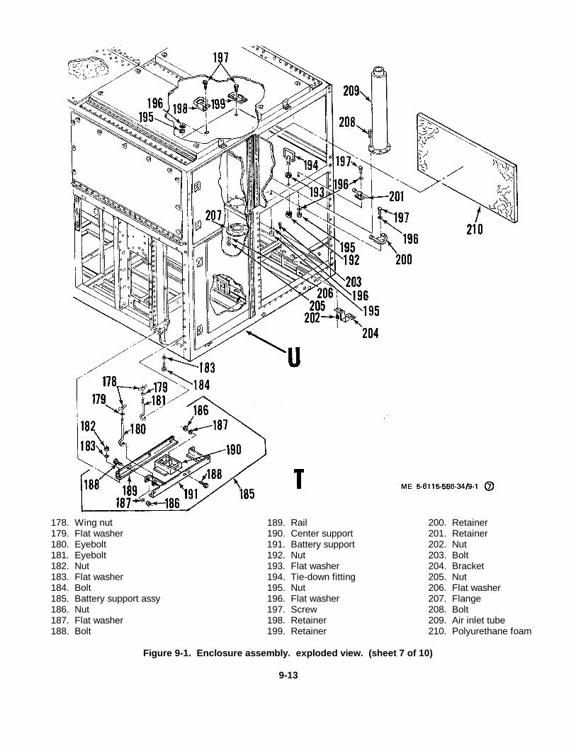
178. Wing nut 189. Rail 200. Retainer179. Flat washer 190. Center support 201. Retainer180. Eyebolt 191. Battery support 202. Nut181. Eyebolt 192. Nut 203. Bolt182. Nut 193. Flat washer 204. Bracket183. Flat washer 194. Tie-down fitting 205. Nut184. Bolt 195. Nut 206. Flat washer185. Battery support assy 196. Flat washer 207. Flange186. Nut 197. Screw 208. Bolt187. Flat washer 198. Retainer 209. Air inlet tube188. Bolt 199. Retainer 210. Polyurethane foam
Figure 9-1. Enclosure assembly. exploded view. (sheet 7 of 10)
9-13
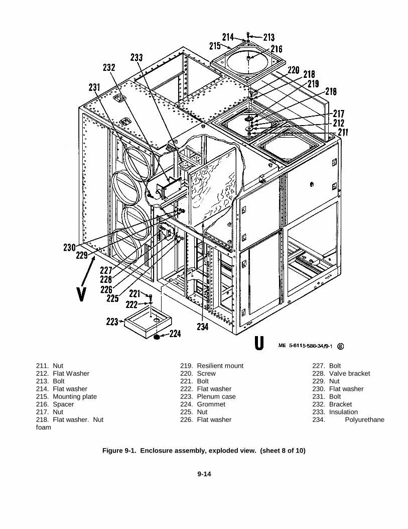
211. Nut 219. Resilient mount 227. Bolt212. Flat Washer 220. Screw 228. Valve bracket213. Bolt 221. Bolt 229. Nut214. Flat washer 222. Flat washer 230. Flat washer215. Mounting plate 223. Plenum case 231. Bolt216. Spacer 224. Grommet 232. Bracket217. Nut 225. Nut 233. Insulation218. Flat washer. Nut 226. Flat washer 234. Polyurethanefoam
Figure 9-1. Enclosure assembly, exploded view. (sheet 8 of 10)
9-14
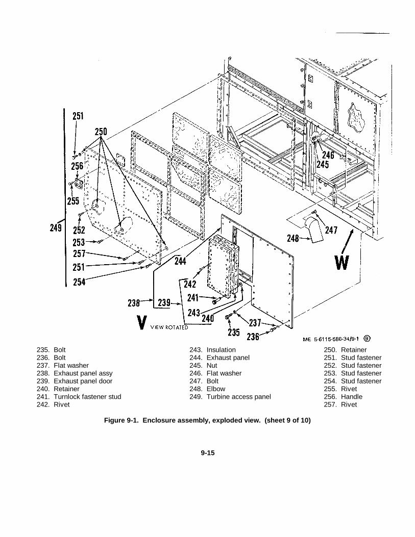
235. Bolt 243. Insulation 250. Retainer236. Bolt 244. Exhaust panel 251. Stud fastener237. Flat washer 245. Nut 252. Stud fastener238. Exhaust panel assy 246. Flat washer 253. Stud fastener239. Exhaust panel door 247. Bolt 254. Stud fastener240. Retainer 248. Elbow 255. Rivet241. Turnlock fastener stud 249. Turbine access panel 256. Handle242. Rivet 257. Rivet
Figure 9-1. Enclosure assembly, exploded view. (sheet 9 of 10)
9-15
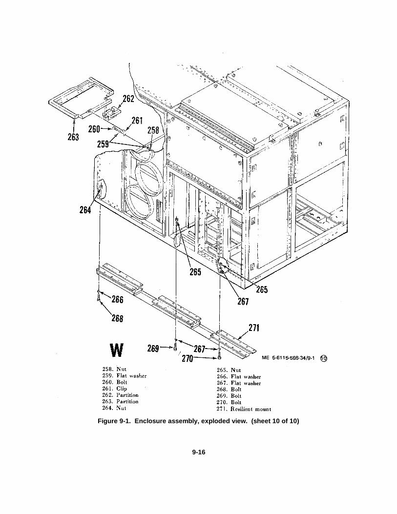
Figure 9-1. Enclosure assembly, exploded view. (sheet 10 of 10)
9-16
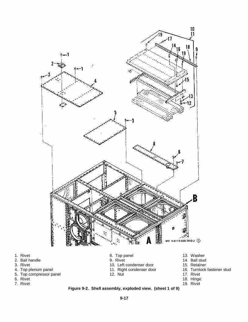
1. Rivet 8. Top panel 13. Washer2. Bail handle 9. Rivet 14. Ball stud3. Rivet 10. Left condenser door 15. Retainer4. Top plenum panel 11. Right condenser door 16. Turnlock fastener stud5. Top compressor panel 12. Nut 17. Rivet6. Rivet 18. Hinge7. Rivet 19. Rivet
Figure 9-2. Shell assembly, exploded view. (sheet 1 of 9)
9-17
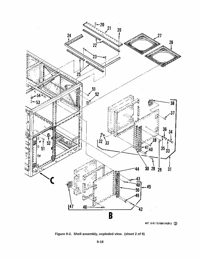
Figure 9-2. Shell assembly, exploded view. (sheet 2 of 9)
9-18

KEY to figure 9-2-Continued: 28. Rivet 37. Rivet 46. Rivet20. Rivet 29. Rivet 38. Lock 47. Lock21. Top panel, right 30. Plate spacer 39. Rivet 48. Rivet22. Plate spacer 31. Condenser door, left front 40. Rivet 49. Rivet23. Rivet 32. Nut 41. Hinge 50. Hinge24. Panel frame 33. Flat washer 42. Rivet 51. Rivet25. Plate spacer 34. Bolt 43. Rivet 52. Latch retainer26. Condenser fan support 35. Flat washer 44. Plate spacer 53. Rivet27. Condenser fan support 36. Tubing 45. Condenser door, right front 54. Receptacle
9-19
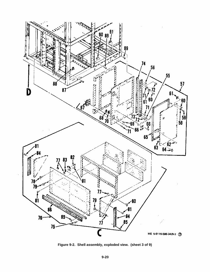
Figure 9-2. Shell assembly, exploded view. (sheet 3 of 9)
9-20

KEY to figure 9-2-Continued: 64. Turnlock fastener stud 73. Hinge 82. Rivet55. Rivet 65. Foam tape 74. Plate spacer 83. Receptacle56. Rivet 66. Rivet 75. Rivet 84. Hinge57. Turbine air inlet door 67. Lock 76. Condenser door, right 85. Rivet58. Screw 68. Protective cap 77. Retainer 86. Hinge59. Tooth lockwasher 69. Rivet 78. Turnlock fastener stud 87. Rivet60. Rivet 70. Receptacle 79. Turnlock fastener stud 88. Latch retainer61. Butt hinge 71. Rivet 80. Turnlock fastener stud 89. Rivet62. Rivet 72. Rivet 81. Rivet 90. Plate nut63. Retainer 91. Plate nut
9-21
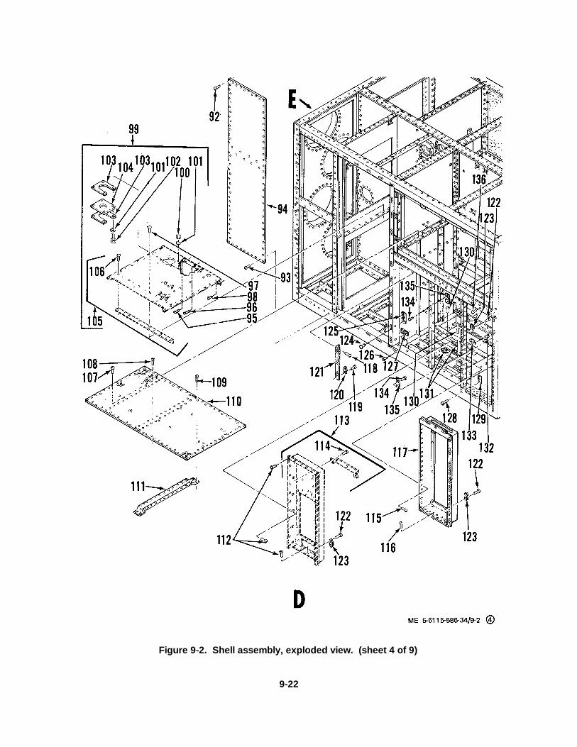
Figure 9-2. Shell assembly, exploded view. (sheet 4 of 9)
9-22
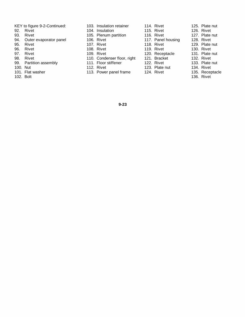
KEY to figure 9-2-Continued: 103. Insulation retainer 114. Rivet 125. Plate nut92. Rivet 104. Insulation 115. Rivet 126. Rivet93. Rivet 105. Plenum partition 116. Rivet 127. Plate nut94. Outer evaporator panel 106. Rivet 117. Panel housing 128. Rivet95. Rivet 107. Rivet 118. Rivet 129. Plate nut96. Rivet 108. Rivet 119. Rivet 130. Rivet97. Rivet 109. Rivet 120. Receptacle 131. Plate nut98. Rivet 110. Condenser floor, right 121. Bracket 132. Rivet99. Partition assembly 111. Floor stiffener 122. Rivet 133. Plate nut100. Nut 112. Rivet 123. Plate nut 134. Rivet101. Flat washer 113. Power panel frame 124. Rivet 135. Receptacle102. Bolt 136. Rivet
9-23
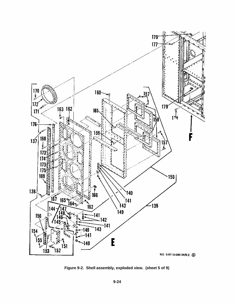
Figure 9-2. Shell assembly, exploded view. (sheet 5 of 9)
9-24

KEY to figure 9-2-Continued: 147. Rod 158. Filter holding frame 169. Hinge137. Rivet 148. Grommet 159. Rivet 170. Rivet138. Rivet 149. Flat washer 160. Rivet 171. Rivet139. Inlet air door assy 150. Door 161. Rivet 172. Flange140. Nut 151. Retainer 162. Retainer 173. Rivet141. Flat washer 152. Turnlock fastener stud 163. Stud fastener 174. Rivet142. Screw 153. Rivet 164. Rivet 175. Rivet143. Spacer 154. Rivet 165. Rivet 176. Plate spacer144. Door positioning arm 155. Rivet 166. Receptacle 177. Rivet145. Wing nut 156. Hinge 167. Rivet 178. Rivet146. Flat washer 157. Rivet 168. Rivet 179. Receptacle
9-25

Figure 9-2. Shell assembly, exploded view. (sheet 6 of 9)
9-26

KEY to figure 9-2-Continued: 185. Hinge 191. Rivet 197. Rivet180. Rivet 186. Retainer 192. Outlet panel frame 198. Receptacle181. Rivet 187. Turnlock fastener stud 193. Retainer 199. Rivet182. Plate spacer 188. Rivet 194. Stud fastener 200. Rivet183. Air outlet door 189. Flange 195. Rivet 201. Plate nut184. Rivet 190. Rivet 196. Foam tape 202. Plate nut
9-27

Figure 9-2. Shell assembly, exploded view. (sheet 7 of 9)
9-28
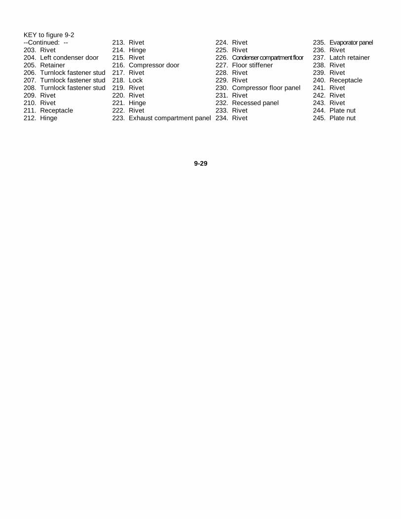
KEY to figure 9-2--Continued: -- 213. Rivet 224. Rivet 235. Evaporator panel203. Rivet 214. Hinge 225. Rivet 236. Rivet204. Left condenser door 215. Rivet 226. Condenser compartment floor 237. Latch retainer205. Retainer 216. Compressor door 227. Floor stiffener 238. Rivet206. Turnlock fastener stud 217. Rivet 228. Rivet 239. Rivet207. Turnlock fastener stud 218. Lock 229. Rivet 240. Receptacle208. Turnlock fastener stud 219. Rivet 230. Compressor floor panel 241. Rivet209. Rivet 220. Rivet 231. Rivet 242. Rivet210. Rivet 221. Hinge 232. Recessed panel 243. Rivet211. Receptacle 222. Rivet 233. Rivet 244. Plate nut212. Hinge 223. Exhaust compartment panel 234. Rivet 245. Plate nut
9-29
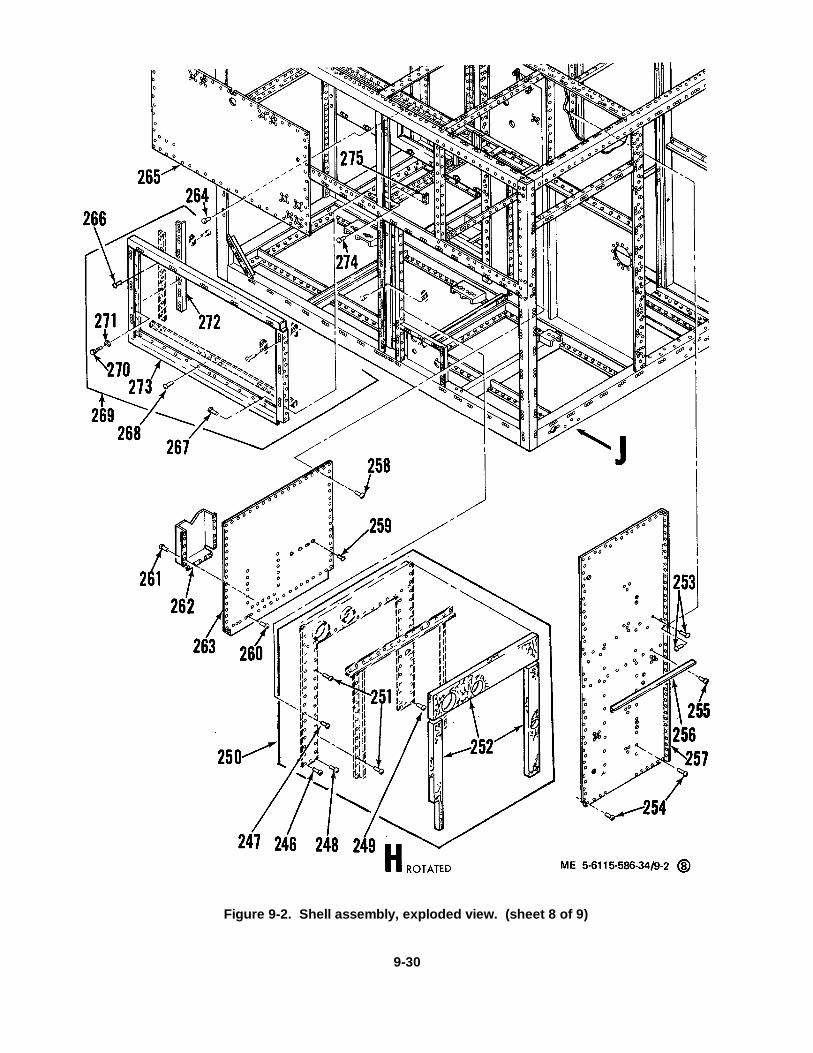
Figure 9-2. Shell assembly, exploded view. (sheet 8 of 9)
9-30

KEY to figure 9-2-Continued:246. Rivet 256. Plenum separator support 266. Rivet247. Rivet 257. Air inlet panel 267. Rivet248. Rivet 258. Rivet 268. Rivet249. Rivet 259. Rivet 269. Condenser support assy250. Combustor compartment panel 260. Rivet 270. Bolt251. Rivet 261. Rivet 271. Flat washer252. Insulation 262. Handbook storage rack 272. Condenser support angle253. Rivet 263. Rear compressor panel 273. Left condenser support254. Rivet 264. Rivet 274. Rivet255. Rivet 265. Condenser panel 275. Latch retainer
9-31
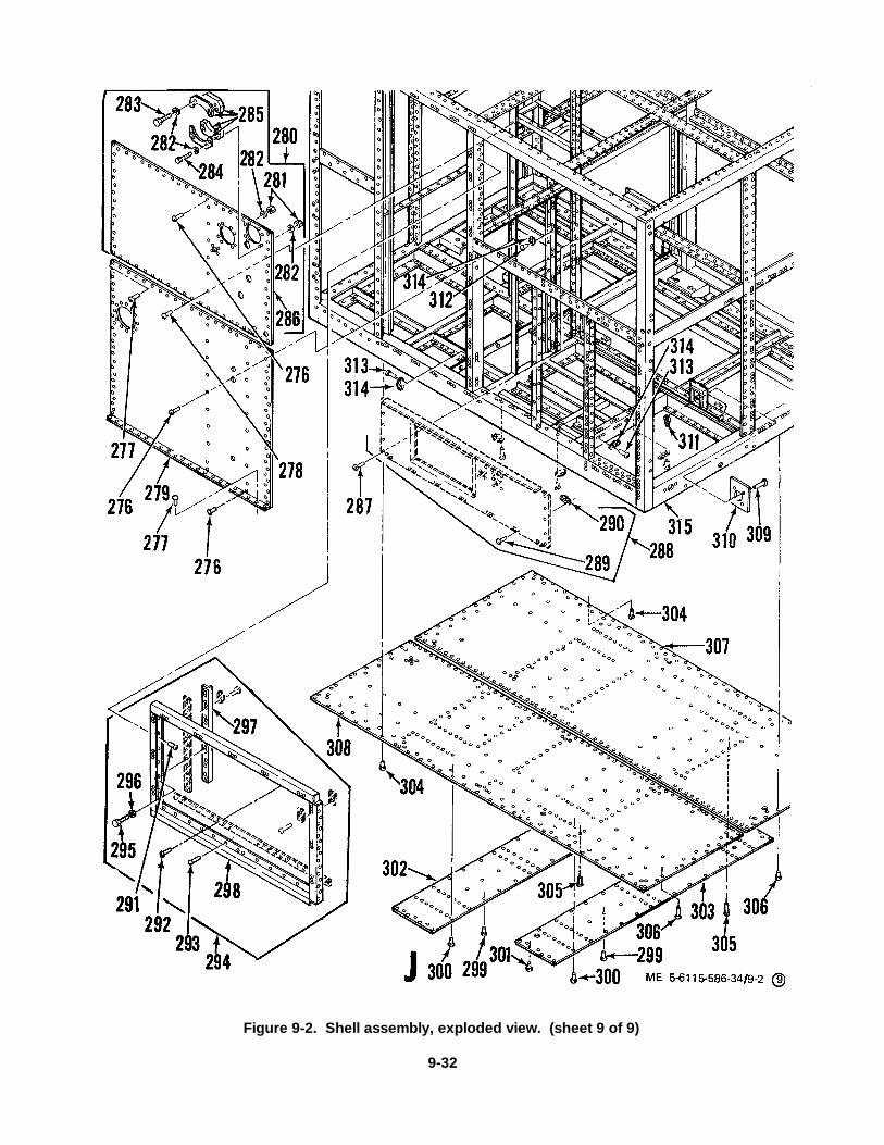
Figure 9-2. Shell assembly, exploded view. (sheet 9 of 9)
9-32

KEY to figure 9-2-Continued:276. Rivet277. Rivet278. Rivet279. Lower plenum panel280. Plenum panel assy281. Nut282. Flat washer283. Bolt284. Bolt285. Cover286. Panel287. Rivet288. Engine bulkhead289. Rivet290. Nut plate291. Rivet292. Rivet293. Rivet294. Right condenser support assy295. Bolt296. Flat washer
297. Condenser support angle298. Right condenser support299. Rivet300. Rivet301. Rivet302. Rear reinforcement plate303. Front reinforcement plate304. Rivet305. Rivet306. Rivet307. Bottom left panel308. Bottom right panel309. Rivet310. Receptacle plate311. Plate nut312. Rivet313. Rivet314. Plate nut315. Enclosure frame
(5) If the components of a subassembly are damaged beyond simple shop repair, replace the entiresubassembly.
(6) Repaint frame assembly with primer (Cati-coat 42GP22 and thinner VK66KP46, Sherwin-Williams Co.,Cleveland, Ohio, or equivalent, no known government specifications) air dry thirty minutes and bake at 150° to 175° F.for one hour. Apply a finish coat of enamel (Federal specification TT-E-527, Color 3412 (Federal Specification TT-595).
c. Assembly.(1} Assemble the shell assembly in reverse order of disassembly procedures (para 9-2 a above).(2) Assemble the enclosure in reverse order of disassembly procedures (para 9-2 a. above).
9-33
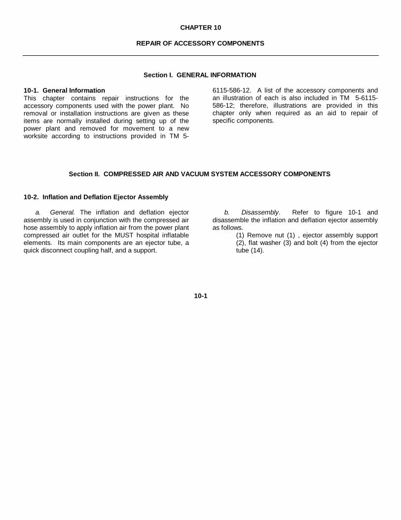
CHAPTER 10
REPAIR OF ACCESSORY COMPONENTS
Section I. GENERAL INFORMATION
10-1. General InformationThis chapter contains repair instructions for theaccessory components used with the power plant. Noremoval or installation instructions are given as theseitems are normally installed during setting up of thepower plant and removed for movement to a newworksite according to instructions provided in TM 5-
6115-586-12. A list of the accessory components andan illustration of each is also included in TM 5-6115-586-12; therefore, illustrations are provided in thischapter only when required as an aid to repair ofspecific components.
Section II. COMPRESSED AIR AND VACUUM SYSTEM ACCESSORY COMPONENTS
10-2. Inflation and Deflation Ejector Assembly
a. General. The inflation and deflation ejectorassembly is used in conjunction with the compressed airhose assembly to apply inflation air from the power plantcompressed air outlet for the MUST hospital inflatableelements. Its main components are an ejector tube, aquick disconnect coupling half, and a support.
b. Disassembly. Refer to figure 10-1 anddisassemble the inflation and deflation ejector assemblyas follows.
(1) Remove nut (1) , ejector assembly support(2), flat washer (3) and bolt (4) from the ejectortube (14).
10-1
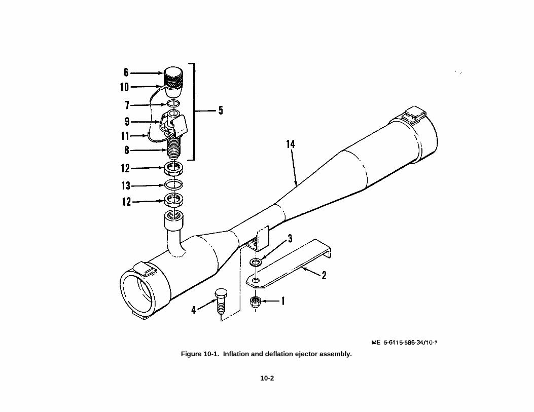
Figure 10-1. Inflation and deflation ejector assembly.
10-2
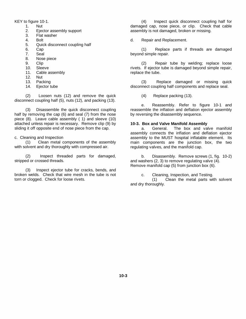
KEY to figure 10-1.1. Nut2. Ejector assembly support3. Flat washer4. Bolt5. Quick disconnect coupling half6. Cap7. Seal8. Nose piece9. Clip10. Sleeve11. Cable assembly12. Nut13. Packing14. Ejector tube
(2) Loosen nuts (12) and remove the quickdisconnect coupling half (5), nuts (12), and packing (13).
(3) Disassemble the quick disconnect couplinghalf by removing the cap (6) and seal (7) from the nosepiece (8). Leave cable assembly ( 1) and sleeve (10)attached unless repair is necessary. Remove clip (9) bysliding it off opposite end of nose piece from the cap.
c. Cleaning and Inspection(1) Clean metal components of the assembly
with solvent and dry thoroughly with compressed air.
(2) Inspect threaded parts for damaged,stripped or crossed threads.
(3) Inspect ejector tube for cracks, bends, andbroken welds. Check that wire mesh in the tube is nottorn or clogged. Check for loose rivets.
(4) Inspect quick disconnect coupling half fordamaged cap, nose piece, or clip. Check that cableassembly is not damaged, broken or missing.
d. Repair and Replacement.
(1) Replace parts if threads are damagedbeyond simple repair.
(2) Repair tube by welding; replace looserivets. If ejector tube is damaged beyond simple repair,replace the tube.
(3) Replace damaged or missing quickdisconnect coupling half components and replace seal.
(4) Replace packing (13).
e. Reassembly. Refer to figure 10-1 andreassemble the inflation and deflation ejector assemblyby reversing the disassembly sequence.
10-3. Box and Valve Manifold Assemblya. General. The box and valve manifold
assembly connects the inflation and deflation ejectorassembly to the MUST hospital inflatable element. Itsmain components are the junction box, the tworegulating valves, and the manifold cap.
b. Disassembly. Remove screws (1, fig. 10-2)and washers (2, 3) to remove regulating valve (4).Remove manifold cap (5) from junction box (6).
c. Cleaning, Inspection, and Testing.(1) Clean the metal parts with solvent
and dry thoroughly.
10-3
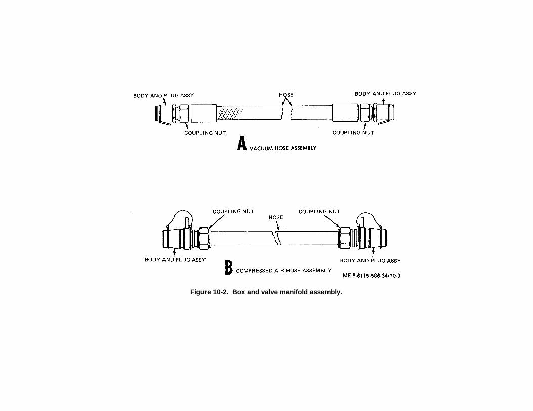
Figure 10-2. Box and valve manifold assembly.
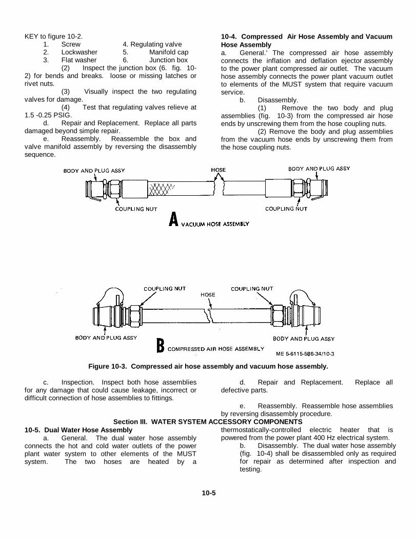
KEY to figure 10-2.1. Screw 4. Regulating valve2. Lockwasher 5. Manifold cap3. Flat washer 6. Junction box
(2) Inspect the junction box (6. fig. 10-2) for bends and breaks. loose or missing latches orrivet nuts.
(3) Visually inspect the two regulatingvalves for damage.
(4) Test that regulating valves relieve at1.5 -0.25 PSIG.
d. Repair and Replacement. Replace all partsdamaged beyond simple repair.
e. Reassembly. Reassemble the box andvalve manifold assembly by reversing the disassemblysequence.
10-4. Compressed Air Hose Assembly and VacuumHose Assemblya. General.' The compressed air hose assemblyconnects the inflation and deflation ejector assemblyto the power plant compressed air outlet. The vacuumhose assembly connects the power plant vacuum outletto elements of the MUST system that require vacuumservice.
b. Disassembly.(1) Remove the two body and plug
assemblies (fig. 10-3) from the compressed air hoseends by unscrewing them from the hose coupling nuts.
(2) Remove the body and plug assembliesfrom the vacuum hose ends by unscrewing them fromthe hose coupling nuts.
Figure 10-3. Compressed air hose assembly and vacuum hose assembly.
c. Inspection. Inspect both hose assembliesfor any damage that could cause leakage, incorrect ordifficult connection of hose assemblies to fittings.
d. Repair and Replacement. Replace alldefective parts.
e. Reassembly. Reassemble hose assembliesby reversing disassembly procedure.
Section III. WATER SYSTEM ACCESSORY COMPONENTS10-5. Dual Water Hose Assembly
a. General. The dual water hose assemblyconnects the hot and cold water outlets of the powerplant water system to other elements of the MUSTsystem. The two hoses are heated by a
thermostatically-controlled electric heater that ispowered from the power plant 400 Hz electrical system.
b. Disassembly. The dual water hose assembly(fig. 10-4) shall be disassembled only as requiredfor repair as determined after inspection andtesting.
10-5
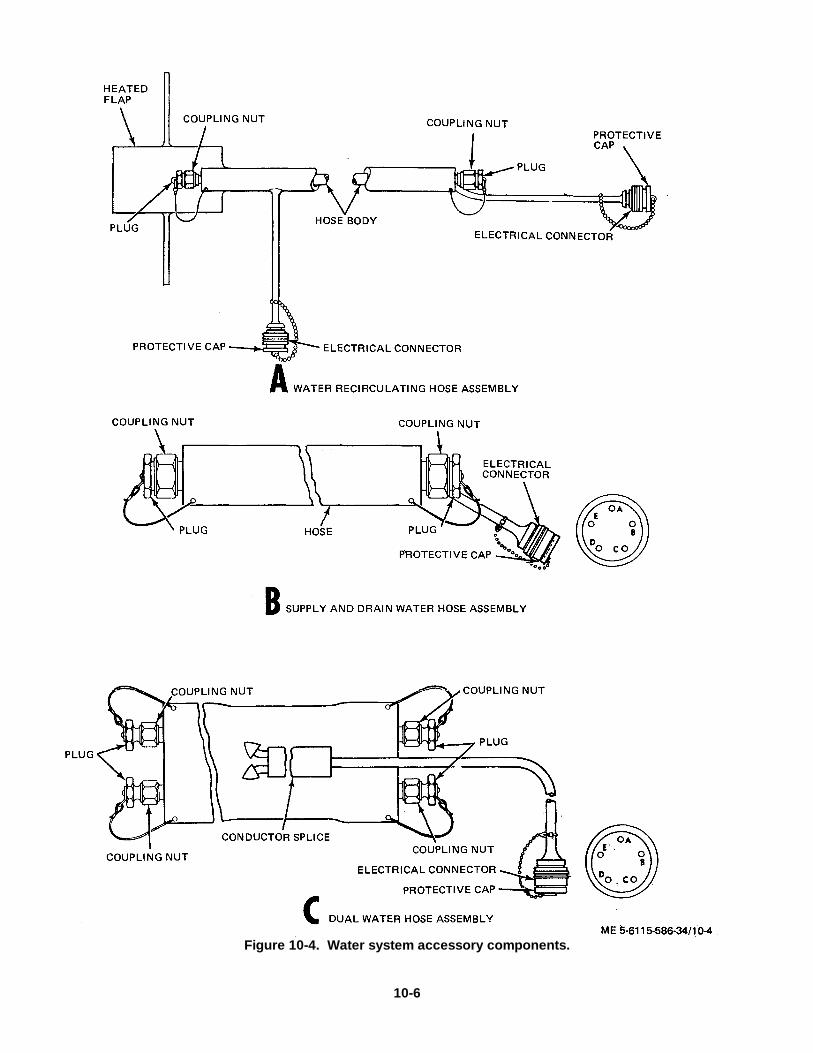
Figure 10-4. Water system accessory components.
10-6
c. Inspection and Testing.
(1) Visually inspect the dual waterhose assembly for damage, signs of leakage, stripped orcrossed threads on coupling nuts and electricalconnectors, missing or damage protective cap or plugs.
(2) Test the heater with 400 Hz, 120VAC. Connector pin arrangement is as follows: pin A:spare, pin B: spare, pin C: 400 Hz, 120 VAC (phase),pin D: 400 Hz, 120 VAC (neutral), pin E: ground.
(3) Test for leaks at 100 PSI waterpressure.
d. Repair and Replacement.
(1) Replace. damaged or missingplugs, connector or protective cap.
(2) If wires are defective in the electricalcable, one of the spare wires (pin A, pin B) may beutilized if the remainder of the cable is in goodcondition. The connector pin must be jumped to thenew pin connection to obtain power through the matingconnector on the power plant, and the new wire must beconnected to the heating element at the cable splice.
(3) If hose assembly is damagedbeyond simple repair and replacement, replace theentire assembly.
10-6. Water Recirculating Hose and Water Supplyand Drain Hose Assemblies
a. General. The water recirculating hoseassembly is utilized to recirculating cold water back tosource to prevent freezing in cold weather operation andfor recirculation of hot water back through the powerplant water system. The water supply and drain hose
assembly delivers water from the source to the powerplant water system inlet.Both hose assemblies are heated bythermostatically-controlled electric heating elementspowered from the power plant 400 Hz electrical system.
b. Disassembly. The water recirculating hoseand' water supply and drain hose assemblies (fig. 10-4)shall be disassembled only as necessary for repairsindicated after inspection and testing.
c. Inspection and Testing.
(1) Visually inspect the hose assembliesfor damage, signs of leakage, stripped or crossedthreads, missing or damaged plugs or protective caps.Inspect heated flap of water recirculating hose assemblyfor visible damage.
(2) Test the heaters with 400 Hz 120VAC.Connector pin arrangement is: pin A: spare, pin B:spare, pin C: 400 Hz, 120 VAC (phase, pin D: 400 Hz,120 VAC (neutral), pin E: ground.
(3) Test for leaks in hoses at 75 PSIwater pressure.
d. Repair and Replacement.
(1) Replace damaged or missingplugs, connector, or protective cap.
(2) If wires are defective in the electricalcable, spare pins A and B may be utilized if remainderof cable is serviceable. Pins must be jumped for properconnection to obtain power through mating connectionpower plant.
Section IV. EXTERNAL FUEL FILTER ASSEMBLY10-7. GeneralThe fuel filter assembly delivers and filters fuel from theexternal fuel fitting. It consists of a dual element filterwith a selector valve, three hose assemblies forconnection to fuel source and one hose assembly withfuel shutoff valve for connection of filters to power plantfuel inlet.
10-8. Disassembly
a. Refer to TM 5-6115-586-12 and remove thetwo filter elements, gaskets, cases, and retainer ringsaccording to instructions provided.
b. Unscrew hoses (fig. 10-5) and fittings andshutoff valve.
c. Remove two nuts, four flat washers, and twobolts to remove filter head assembly from fuel filterbracket.
10-7
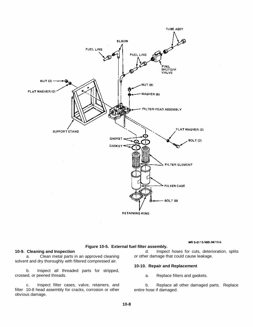
Figure 10-5. External fuel filter assembly.10-9. Cleaning and Inspection
a. Clean metal parts in an approved cleaningsolvent and dry thoroughly with filtered compressed air.
b. Inspect all threaded parts for stripped,crossed, or peened threads.
c. Inspect filter cases, valve, retainers, andfilter 10-8 head assembly for cracks, corrosion or otherobvious damage.
d. Inspect hoses for cuts, deterioration, splitsor other damage that could cause leakage.
10-10. Repair and Replacement
a. Replace filters and gaskets.
b. Replace all other damaged parts. Replaceentire hose if damaged.
10-8
10-11. ReassemblyReassemble the external fuel filter assembly byreversing disassembly procedure. Refer to TM 56115-
586-12 for instructions regarding installation of filtersand gaskets.
Section V. ELECTRICAL CABLE ACCESSORY COMPONENTS10-12. General
a. The electrical cable accessory componentsare the 400 Hz electrical power output cableassembly, the 60 Hz electrical power output cableassembly, the 400 Hz remote power cable assembly,DC electrical power standby cable assembly, externalDC electrical power input cable assembly, externalbattery DC power cable assembly.
b. Refer to TM 5-6115-586-12 for a descriptionof use of the cable assemblies, illustrations, and wirerun charts.
c. This section contains inspection, testing,and replacement instructions for the cable assemblies.
10-13. 400 Hz Electrical Power Output CableAssembly
a. Visually inspect the cable assembly fordamaged connectors or connector covers, sleeves, orcables.
b. Refer to TM 5-6115-586-12 and testindividual wires for continuity.
c. Replace the cable assembly if inspectionand/ or testing reveals damage or lack of continuity inindividual wires.
10-14. 60 Hz Electrical Power Output CableAssembly
a. Visually inspect the cable assembly fordamaged connectors or connector covers, sleeves, orcables.
b. Refer to TM 5-6115-586-12 and testindividual wires for continuity.
c. Replace the cable assembly if inspectionand / or testing reveals damage or lack of continuity inindividual wires.
10-15. 400 Hz Remote Power. Cable Assemblya. Visually inspect the cable assembly for dam
aged connectors or connector covers, sleeves, orcables.
b. Refer to TM 5-6115-586-12 and testindividual wires for continuity.
c. Replace the cable assembly if inspectionand / or testing reveals damage or lack of continuity inindividual wires.
10-16. DC Electrical Power Standby CableAssembly
a. Visually inspect the cable assembly fordamaged connectors or connector covers, sleeves, orcables.
b. Refer to TM 5-6115-586-12 and testindividual wires for continuity.
c. Replace the cable assembly if inspectionand /or testing reveals damage or lack of continuity inindividual wires.
10-17. External DC Electrical Power Input CableAssembly
a. Visually inspect the cable assembly fordamaged connectors or connector covers, sleeves, orcables.
b. Refer to TM 5-6115-586-12 and testindividual wires for continuity.
c. Replace the cable assembly if inspectionand /or testing reveals damage or lack of continuity inindividual wires.
10-18. External Battery DC Power CableAssembly
a. Visually inspect cable assembly fordamaged connector, lugs, adapters, or cable.
b. Test continuity of the two wires.
c. Replace the cable assembly if inspectionand / or testing reveals damage or lack of continuity inindividual wires.
Section VI. CONDITIONED AIR SYSTEM ACCESSORY COMPONENTS10-19. Coupling Assembly
a. Inspection.Visually inspect the two clamps (fig. 10-6) andthe flanged coupling for damage and check thatthe clamps operate satisfactorily.
10-9
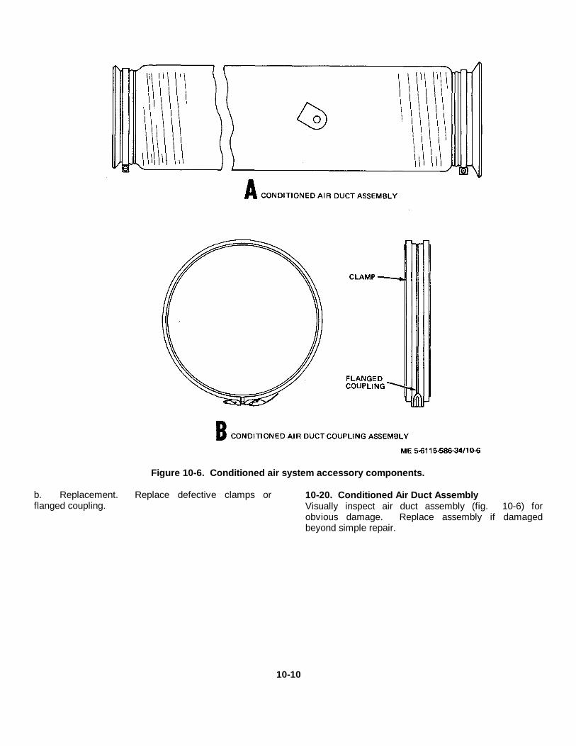
Figure 10-6. Conditioned air system accessory components.
b. Replacement. Replace defective clamps orflanged coupling.
10-20. Conditioned Air Duct AssemblyVisually inspect air duct assembly (fig. 10-6) forobvious damage. Replace assembly if damagedbeyond simple repair.
10-10
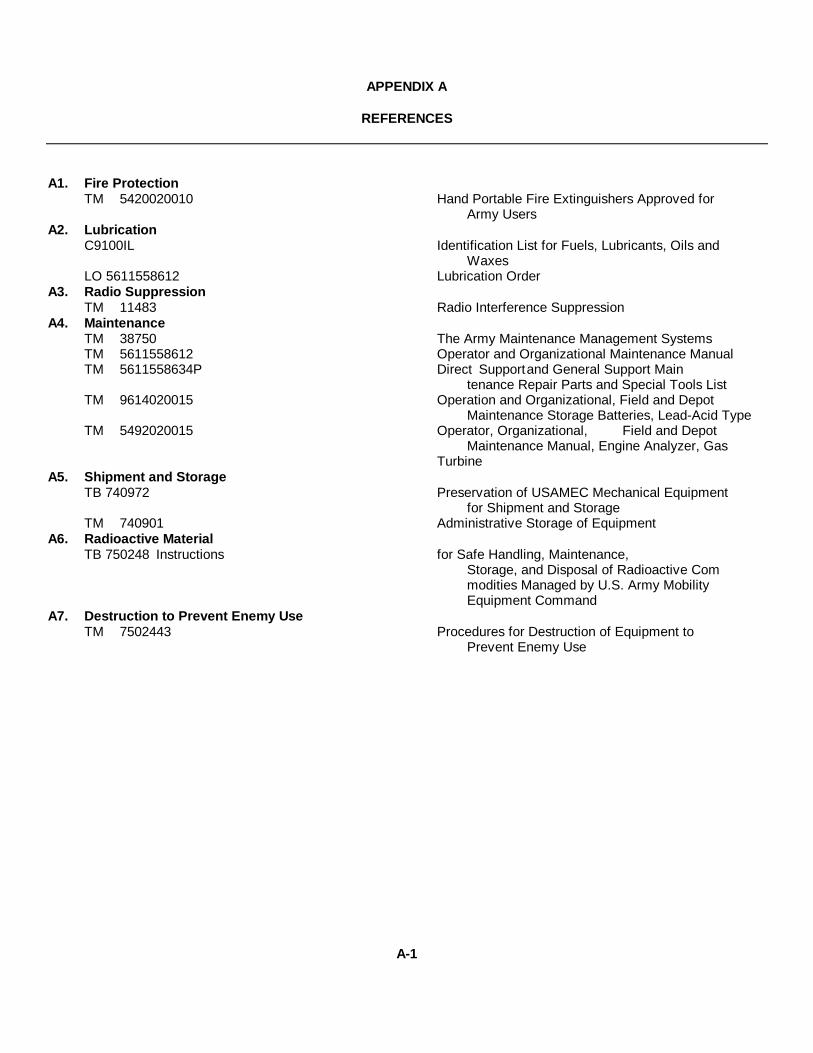
APPENDIX A
REFERENCES
A1. Fire ProtectionTM 5420020010 Hand Portable Fire Extinguishers Approved for
Army UsersA2. Lubrication
C9100IL Identification List for Fuels, Lubricants, Oils andWaxes
LO 5611558612 Lubrication OrderA3. Radio Suppression
TM 11483 Radio Interference SuppressionA4. Maintenance
TM 38750 The Army Maintenance Management SystemsTM 5611558612 Operator and Organizational Maintenance ManualTM 5611558634P Direct Supportand General Support Main
tenance Repair Parts and Special Tools ListTM 9614020015 Operation and Organizational, Field and Depot
Maintenance Storage Batteries, Lead-Acid TypeTM 5492020015 Operator, Organizational, Field and Depot
Maintenance Manual, Engine Analyzer, GasTurbine
A5. Shipment and StorageTB 740972 Preservation of USAMEC Mechanical Equipment
for Shipment and StorageTM 740901 Administrative Storage of Equipment
A6. Radioactive MaterialTB 750248 Instructions for Safe Handling, Maintenance,
Storage, and Disposal of Radioactive Commodities Managed by U.S. Army MobilityEquipment Command
A7. Destruction to Prevent Enemy UseTM 7502443 Procedures for Destruction of Equipment to
Prevent Enemy Use
A-1
INDEX
Paragraph PageAC power wire harness assembly (13217E4158) ..............................................................................5-21 5-28Accessory components:
Compressed air and vacuum system:Box and valve manifold assembly ................................................................................10-3 10-3Compressed air hose assembly and vacuum hose assembly .......................................10-4 10-5Inflation and deflation ejector assembly ........................................................................10-2 10-1
Conditioned air system:Conditioned air duct assembly ....................................................................................10-20 10-10Coupling assembly .....................................................................................................10-19 10-9
Electrical Cables:DC electrical power standby cable assembly ...............................................................10-16 10-9External battery DC power cable assembly .................................................................10-18 10-9External DC electrical power input cable assembly ......................................................10-17 10-9General ...............................................................................................................10-12 10-9400 Hz electrical power output cable assembly ...........................................................10-13 '400 Hz remote power cable assembly .........................................................................10-15 10-9'60 Hz electrical power output cable assembly .............................................................10-14 10-9
External fuel filter assembly:Cleaning and inspection ..............................................................................................10-9 10-8Disassembly ................................................................................................................10-8 10-7General ................................................................................................................10-7 10-7Reassembly ...............................................................................................................10-11 10-9Repair and replacement...............................................................................................10-10 10-8
General information ...............................................................................................................10-1 10-1Water system:
Dual water hose assembly ...........................................................................................10-5 10-5Water recirculating hose and water supply and drain hose assemblies .........................10-6 10-7
Accessory gearcase assembly:Cleaning, inspection and repair ..............................................................................................3-18 3-32Disassembly ................................................................................................................3-17 3-31General ................................................................................................................3-15 3-30Installation ................................................................................................................3-20 3-34Reassembly 3-19.........................................................................................................3-32Removal ................................................................................................................3-16 3-30
Accessory gearcase nut and bolt torque values ................................................................................1-6q 1-3Accessory gearcase repair and replacement standards ....................................................................1-6p 1-2Air conditioning compressor replacement standards ......................................................................... 1-6t 1-3Air conditioning system branched wire harness assembly (13217E4146) ...........................................5-8 5-9Air conditioning wire harness assembly (13217E41451 .....................................................................5-9 5-10Air inlet duct and screen assembly ....................................................................................................4-7 4-3Air inlet plenum assembly 4-8............................................................................................................4-5Anti-ice thermostat wire harness assembly (13217E4133) ................................................................5-14 5-16Auxiliary power tray assembly:
Removal and installation of ....................................................................................................2-13 2-27Repair instructions 5-28.........................................................................................................5-43
Battery wire harness assembly:(13217E4154 (Skid) ...............................................................................................................5-36 5-64(13217E4168) ................................................................................................................5-24 5-33
Bleed air and exhaust heating installation, repair of:Ducting, tubing and plumbing fittings ......................................................................................7-2 7-1Exhaust system .................................................................................................................7-4 7-7General .................................................................................................................7-1 7-1Heat exchanger .................................................................................................................7-3 7-7Lines and fittings .................................................................................................................7-5 '7-8
Bleed air lines and fittings 7-5............................................................................................................7-8Box and valve manifold assembly ....................................................................................................10-3 10-3Cleaning instructions (general)...........................................................................................................2-7 2-20Cold water pump replacement standards .........................................................................................1-6z 1-4Compressed air and vacuum system: (accessory components)
Box and valve manifold assembly ..........................................................................................10-3 10-3Compressed air hose assembly and vacuum hose assembly .................................................10-4 10-5Inflation and deflation ejector assembly .................................................................................10-2 10-1
I-1
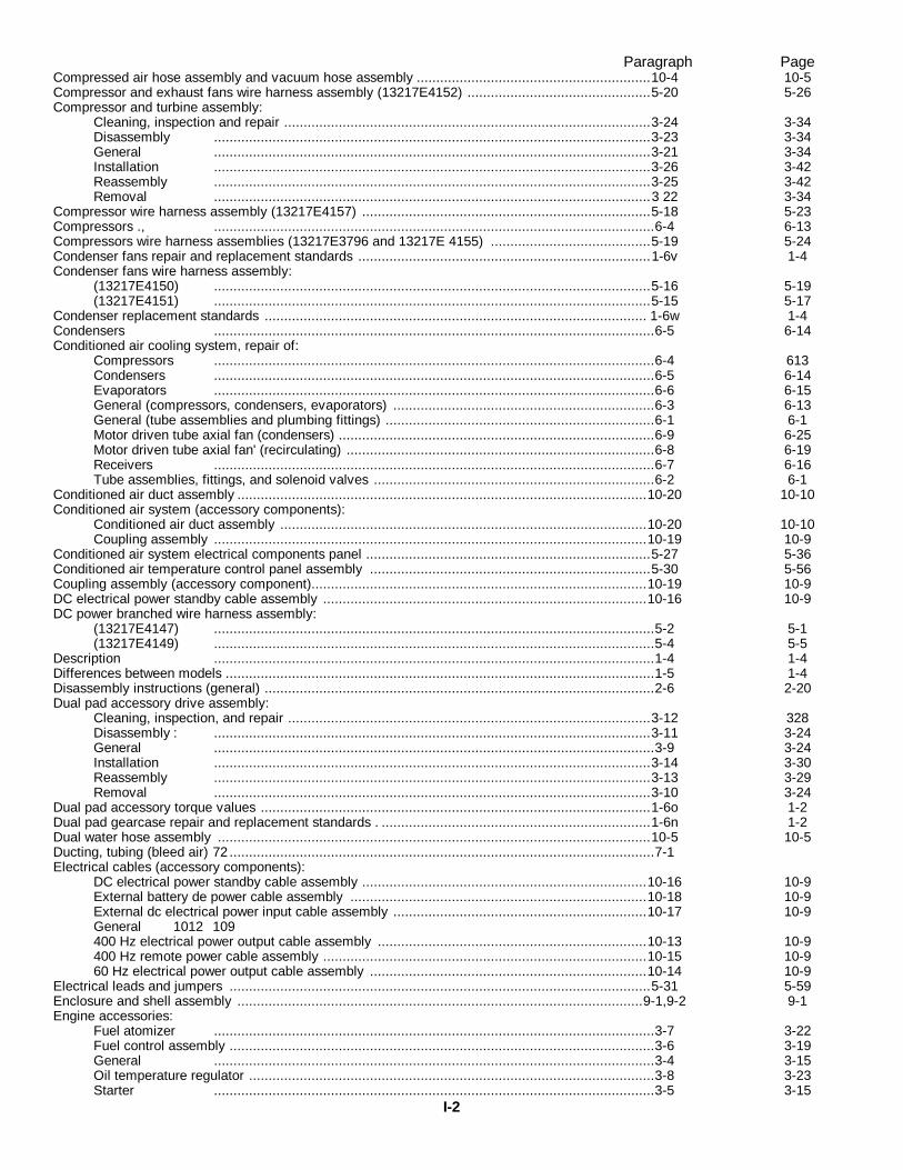
Paragraph PageCompressed air hose assembly and vacuum hose assembly ............................................................10-4 10-5Compressor and exhaust fans wire harness assembly (13217E4152) ...............................................5-20 5-26Compressor and turbine assembly:
Cleaning, inspection and repair ..............................................................................................3-24 3-34Disassembly ................................................................................................................3-23 3-34General ................................................................................................................3-21 3-34Installation ................................................................................................................3-26 3-42Reassembly ................................................................................................................3-25 3-42Removal ................................................................................................................3 22 3-34
Compressor wire harness assembly (13217E4157) ..........................................................................5-18 5-23Compressors ., .................................................................................................................6-4 6-13Compressors wire harness assemblies (13217E3796 and 13217E 4155) .........................................5-19 5-24Condenser fans repair and replacement standards ...........................................................................1-6v 1-4Condenser fans wire harness assembly:
(13217E4150) ................................................................................................................5-16 5-19(13217E4151) ................................................................................................................5-15 5-17
Condenser replacement standards .................................................................................................. 1-6w 1-4Condensers .................................................................................................................6-5 6-14Conditioned air cooling system, repair of:
Compressors .................................................................................................................6-4 613Condensers .................................................................................................................6-5 6-14Evaporators .................................................................................................................6-6 6-15General (compressors, condensers, evaporators) ...................................................................6-3 6-13General (tube assemblies and plumbing fittings) .....................................................................6-1 6-1Motor driven tube axial fan (condensers) .................................................................................6-9 6-25Motor driven tube axial fan' (recirculating) ...............................................................................6-8 6-19Receivers .................................................................................................................6-7 6-16Tube assemblies, fittings, and solenoid valves ........................................................................6-2 6-1
Conditioned air duct assembly .........................................................................................................10-20 10-10Conditioned air system (accessory components):
Conditioned air duct assembly ..............................................................................................10-20 10-10Coupling assembly ...............................................................................................................10-19 10-9
Conditioned air system electrical components panel .........................................................................5-27 5-36Conditioned air temperature control panel assembly ........................................................................5-30 5-56Coupling assembly (accessory component)......................................................................................10-19 10-9DC electrical power standby cable assembly ...................................................................................10-16 10-9DC power branched wire harness assembly:
(13217E4147) .................................................................................................................5-2 5-1(13217E4149) .................................................................................................................5-4 5-5
Description .................................................................................................................1-4 1-4Differences between models ..............................................................................................................1-5 1-4Disassembly instructions (general) ....................................................................................................2-6 2-20Dual pad accessory drive assembly:
Cleaning, inspection, and repair .............................................................................................3-12 328Disassembly : ................................................................................................................3-11 3-24General .................................................................................................................3-9 3-24Installation ................................................................................................................3-14 3-30Reassembly ................................................................................................................3-13 3-29Removal ................................................................................................................3-10 3-24
Dual pad accessory torque values ....................................................................................................1-6o 1-2Dual pad gearcase repair and replacement standards . .....................................................................1-6n 1-2Dual water hose assembly ...............................................................................................................10-5 10-5Ducting, tubing (bleed air) 72 .............................................................................................................7-1Electrical cables (accessory components):
DC electrical power standby cable assembly .........................................................................10-16 10-9External battery de power cable assembly ............................................................................10-18 10-9External dc electrical power input cable assembly .................................................................10-17 10-9General 1012 109400 Hz electrical power output cable assembly .....................................................................10-13 10-9400 Hz remote power cable assembly ...................................................................................10-15 10-960 Hz electrical power output cable assembly .......................................................................10-14 10-9
Electrical leads and jumpers ............................................................................................................5-31 5-59Enclosure and shell assembly ........................................................................................................9-1,9-2 9-1Engine accessories:
Fuel atomizer .................................................................................................................3-7 3-22Fuel control assembly .............................................................................................................3-6 3-19General .................................................................................................................3-4 3-15Oil temperature regulator ........................................................................................................3-8 3-23Starter .................................................................................................................3-5 3-15
I-2
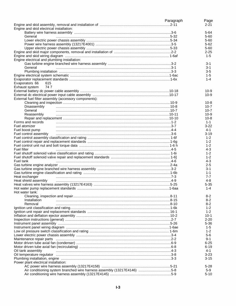
Paragraph PageEngine and skid assembly, removal and installation of .....................................................................2-11 2-21Engine and skid electrical installation:
Battery wire harness assembly ...............................................................................................3-6 5-64General ................................................................................................................5-32 5-60Lower electric power chassis assembly ..................................................................................5-34 5-60Power wire harness assembly (13217E4001) ..........................................................................3-5 5-62Upper electric power chassis assembly ..................................................................................5-33 5-60
Engine and skid major components, removal and installation of ........................................................2-2 2-25Engine and skid wiring diagram ...................................................................................................... 1-6af 1-5Engine electrical and plumbing installation:
Gas turbine engine branched wire harness assembly ..............................................................3-2 3-1General .................................................................................................................3-1 3-1Plumbing installation ..............................................................................................................3-3 3-5
Engine electrical system schematic .................................................................................................1-6ac 1-5Evaporator replacement standards ...................................................................................................1-6x 1-4Evaporators 66 615Exhaust system 74 7External battery dc power cable assembly .......................................................................................10-18 10-9External dc electrical power input cable assembly ...........................................................................10-17 10-9External fuel filter assembly (accessory components):
Cleaning and inspection .........................................................................................................10-9 10-8Disassembly ................................................................................................................10-8 10-7General ................................................................................................................10-7 10-7Reassembly ...............................................................................................................10-11 10-9Repair and replacement ........................................................................................................10-10 10-8
Forms and records .................................................................................................................1-2 1-1Fuel atomizer .................................................................................................................3-7 3-22Fuel boost pump .................................................................................................................4-4 4-1Fuel control assembly .................................................................................................................3-6 3-19Fuel control assembly classification and rating ................................................................................. 1-6f 1-2Fuel control repair and replacement standards .................................................................................1-6g 1-2Fuel control unit nut and bolt torque data ........................................................................................ 1-6 h 1-2Fuel filter .................................................................................................................4-5 4-3Fuel shutoff solenoid valve classification and rating .......................................................................... 1-6i 1-2Fuel shutoff solenoid valve repair and replacement standards .......................................................... 1-6] 1-2Fuel tank .................................................................................................................4-6 4-3Gas turbine engine analyzer .............................................................................................................2-4a 2-5Gas turbine engine branched wire harness assembly ........................................................................3-2 3-1Gas turbine engine classification and rating .....................................................................................1-6b 1-1Heat exchanger .................................................................................................................7-3 7-7Heat shield assembly .................................................................................................................4-9 4-8Heat valves wire harness assembly (13217E4163) ...........................................................................5-25 5-35Hot water pump replacement standards ..........................................................................................1-6aa 1-4Hot water tank:
Cleaning, inspection and repair...............................................................................................8-11 8-2Installation ................................................................................................................8-15 8-2Removal ................................................................................................................8-10 8-2
Ignition unit classification and rating..................................................................................................1-6k 1-2Ignition unit repair and replacement standards .................................................................................16-1 1-2Inflation and deflation ejector assembly ............................................................................................10-2 10-1Inspection instructions (general) ........................................................................................................2-7 2-20Instrument panel assembly ..............................................................................................................5-26 5-36Instrument panel wiring diagram .....................................................................................................1-6ae 1-5Low oil pressure switch classification and rating .............................................................................. 1-6m 1-2Lower electric power chassis assembly .............................................................................................3-4 5-6Maintenance repair parts .................................................................................................................2-2 9-1Motor driven tube axial fan (condenser) .............................................................................................6-9 6-25Motor driven tube axial fan (recirculating) ..........................................................................................6-8 6-19Oil tank assembly .................................................................................................................4-3 4-1Oil temperature regulator .................................................................................................................3-8 3-23Plumbing installation, engine ............................................................................................................3-3 3-15Power plant electrical installation:
AC power wire harness assembly (13217E4158) ...................................................................5-21 5-28Air conditioning system branched wire harness assembly (13217E4146) ................................5-8 5-9Air conditioning wire harness assembly (13217E4145) ............................................................5-9 5-10
I-3
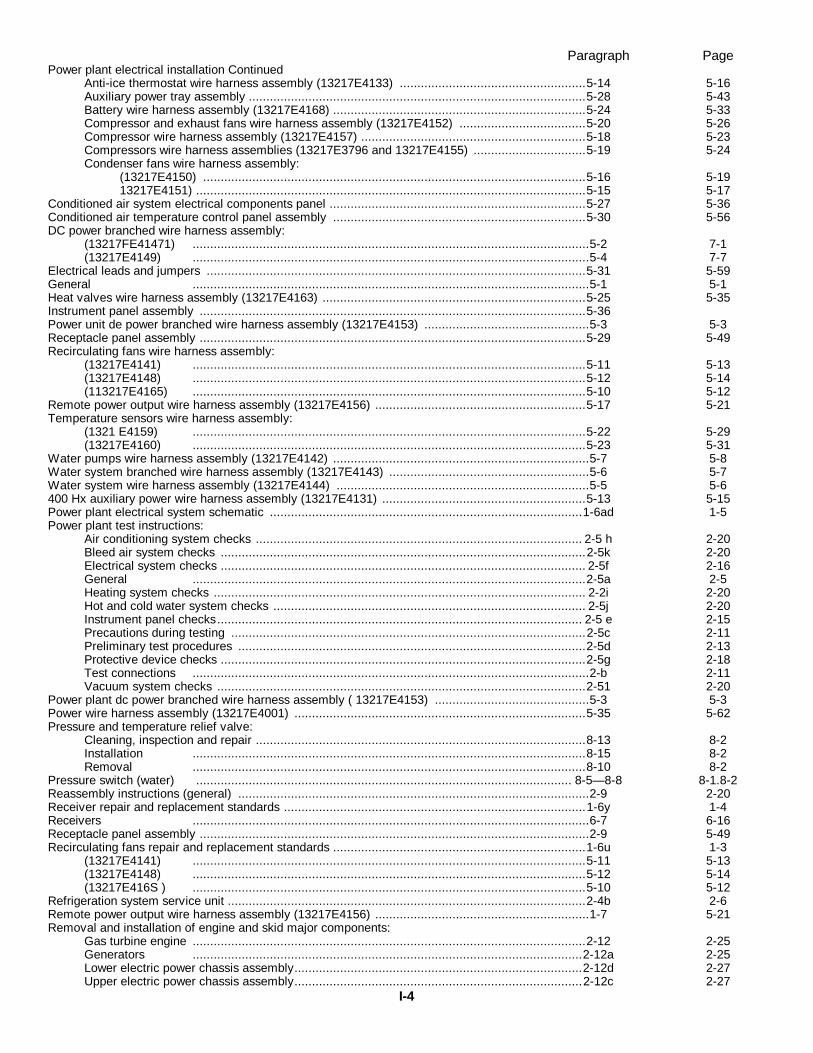
Paragraph PagePower plant electrical installation Continued
Anti-ice thermostat wire harness assembly (13217E4133) .....................................................5-14 5-16Auxiliary power tray assembly ................................................................................................5-28 5-43Battery wire harness assembly (13217E4168) ........................................................................5-24 5-33Compressor and exhaust fans wire harness assembly (13217E4152) ....................................5-20 5-26Compressor wire harness assembly (13217E4157) ................................................................5-18 5-23Compressors wire harness assemblies (13217E3796 and 13217E4155) ................................5-19 5-24Condenser fans wire harness assembly:
(13217E4150) .............................................................................................................5-16 5-1913217E4151) ...............................................................................................................5-15 5-17
Conditioned air system electrical components panel .........................................................................5-27 5-36Conditioned air temperature control panel assembly ........................................................................5-30 5-56DC power branched wire harness assembly:
(13217FE41471) .................................................................................................................5-2 7-1(13217E4149) .................................................................................................................5-4 7-7
Electrical leads and jumpers ............................................................................................................5-31 5-59General .................................................................................................................5-1 5-1Heat valves wire harness assembly (13217E4163) ...........................................................................5-25 5-35Instrument panel assembly ..............................................................................................................5-36Power unit de power branched wire harness assembly (13217E4153) ...............................................5-3 5-3Receptacle panel assembly ..............................................................................................................5-29 5-49Recirculating fans wire harness assembly:
(13217E4141) ................................................................................................................5-11 5-13(13217E4148) ................................................................................................................5-12 5-14(113217E4165) ................................................................................................................5-10 5-12
Remote power output wire harness assembly (13217E4156) ............................................................5-17 5-21Temperature sensors wire harness assembly:
(1321 E4159) ................................................................................................................5-22 5-29(13217E4160) ................................................................................................................5-23 5-31
Water pumps wire harness assembly (13217E4142) .........................................................................5-7 5-8Water system branched wire harness assembly (13217E4143) .........................................................5-6 5-7Water system wire harness assembly (13217E4144) ........................................................................5-5 5-6400 Hx auxiliary power wire harness assembly (13217E4131) ..........................................................5-13 5-15Power plant electrical system schematic .........................................................................................1-6ad 1-5Power plant test instructions:
Air conditioning system checks ............................................................................................. 2-5 h 2-20Bleed air system checks ........................................................................................................2-5k 2-20Electrical system checks ........................................................................................................ 2-5f 2-16General ................................................................................................................2-5a 2-5Heating system checks .......................................................................................................... 2-2i 2-20Hot and cold water system checks ......................................................................................... 2-5j 2-20Instrument panel checks........................................................................................................ 2-5 e 2-15Precautions during testing .....................................................................................................2-5c 2-11Preliminary test procedures ...................................................................................................2-5d 2-13Protective device checks ........................................................................................................2-5g 2-18Test connections .................................................................................................................2-b 2-11Vacuum system checks .........................................................................................................2-51 2-20
Power plant dc power branched wire harness assembly ( 13217E4153) ............................................5-3 5-3Power wire harness assembly (13217E4001) ...................................................................................5-35 5-62Pressure and temperature relief valve:
Cleaning, inspection and repair ..............................................................................................8-13 8-2Installation ................................................................................................................8-15 8-2Removal ................................................................................................................8-10 8-2
Pressure switch (water) ........................................................................................................... 8-5— 8-8 8-1.8-2Reassembly instructions (general) ....................................................................................................2-9 2-20Receiver repair and replacement standards ......................................................................................1-6y 1-4Receivers .................................................................................................................6-7 6-16Receptacle panel assembly ...............................................................................................................2-9 5-49Recirculating fans repair and replacement standards ........................................................................1-6u 1-3
(13217E4141) ................................................................................................................5-11 5-13(13217E4148) ................................................................................................................5-12 5-14(13217E416S ) ................................................................................................................5-10 5-12
Refrigeration system service unit ......................................................................................................2-4b 2-6Remote power output wire harness assembly (13217E4156) .............................................................1-7 5-21Removal and installation of engine and skid major components:
Gas turbine engine ................................................................................................................2-12 2-25Generators ...............................................................................................................2-12a 2-25Lower electric power chassis assembly..................................................................................2-12d 2-27Upper electric power chassis assembly..................................................................................2-12c 2-27
I-4
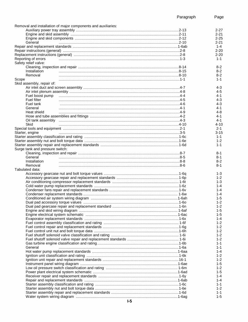
Paragraph Page
Removal and installation of major components and auxiliaries:Auxiliary power tray assembly ................................................................................................2-13 2-27Engine and skid assembly .....................................................................................................2-11 2-21Engine and skid components .................................................................................................2-12 2-25General ................................................................................................................2-10 2-21
Repair and replacement standards ..................................................................................................1-6ab 1-4Repair instructions (general) .............................................................................................................2-8 2-20Replacement instructions (general) ...................................................................................................2-8 2-20Reporting of errors .................................................................................................................1-3 1-1Safety relief valve:
Cleaning, inspection and repair ..............................................................................................8-14 8-2Installation ................................................................................................................8-15 8-2Removal ................................................................................................................8-10 8-2
Scope .................................................................................................................1-1 1-1Skid assembly, repair of:
Air inlet duct and screen assembly ..........................................................................................4-7 4-3Air inlet plenum assembly .......................................................................................................4-8 4-5Fuel boost pump .................................................................................................................4-4 4-1Fuel filter .................................................................................................................4-5 4-3Fuel tank ................................................................................................................4-6 4-3General .................................................................................................................4-1 4-1Heat shield .................................................................................................................4-9 4-8Hose and tube assemblies and fittings ....................................................................................4-2 4-1Oil tank assembly .................................................................................................................4-3 4-1Skid ................................................................................................................4-10 4-10
Special tools and equipment .............................................................................................................2-1 2-1Starter, engine .................................................................................................................3-5 3-15Starter assembly classification and rating ........................................................................................1-6c 1-1Starter assembly nut and bolt torque data ........................................................................................1-6e 1-2Starter assembly repair and replacement standards .........................................................................1-6d 1-1Surge tank and pressure switch:
Cleaning, inspection and repair ...............................................................................................8-7 8-1General .................................................................................................................8-5 8-1Installation .................................................................................................................8-8 8-2Removal .................................................................................................................8-6 8-1
Tabulated data:Accessory gearcase nut and bolt torque values ......................................................................1-6q 1-3Accessory gearcase repair and replacement standards ..........................................................1-6p 1-2Air conditioning compressor replacement standards .............................................................. 1-6t 1-3Cold water pump replacement standards ...............................................................................1-6z 1-4Condenser fans repair and replacement standards .................................................................1-6v 1-4Condenser replacement standards ........................................................................................ 1-6w 1-4Conditioned air system wiring diagram .................................................................................1-6ah 1-5Dual pad accessory torque values .........................................................................................1-6o 1-2Dual pad gearcase repair and replacement standard ..............................................................1-6n 1-2Engine and skid wiring diagram ............................................................................................ 1-6af 1-5Engine electrical system schematic ......................................................................................1-6ac 1-5Evaporator replacement standards ........................................................................................1-6x 1-4Fuel control assembly classification and rating ...................................................................... 1-6f 1-2Fuel control repair and replacement standards .......................................................................1-6g 1-2Fuel control unit nut and bolt torque data ...............................................................................1-6h 1-2Fuel shutoff solenoid valve classification and rating ............................................................... 1-6i 1-2Fuel shutoff solenoid valve repair and replacement standards ................................................ 1-6i 1-2Gas turbine engine classification and rating ............................................................................1-6b 1-1General ................................................................................................................1-6a 1-1Hot water pump replacement standards ................................................................................1-6aa 1-4Ignition unit classification and rating ......................................................................................1-6k 1-2Ignition unit repair and replacement standards .......................................................................16-1 1-2Instrument panel wiring diagram ...........................................................................................1-6ae 1-5Low oil pressure switch classification and rating ................................................................... 1-6m 1-2Power plant electrical system schematic ...............................................................................1-6ad 1-5Receiver repair and replacement standards ...........................................................................1-6y 1-4Repair and replacement standards .......................................................................................1-6ab 1-4Starter assembly classification and rating ..............................................................................1-6c 1-1Starter assembly nut and bolt torque data ..............................................................................1-6e 1-2Starter assembly repair and replacement standards ...............................................................1-6d 1-1Water system wiring diagram ...............................................................................................1-6ag 1-5
I-5
Paragraph PageTabulated data Continued
400 Hz generator repair and replacement standards .............................................................. 1-6r 1-360 Hz generator repair and replacement standards ................................................................1-6s 1-3
Temperature sensors wire harness assembly:(13217E4159) ................................................................................................................5-22 5-29(13217E4160) . ................................................................................................................5-23 5-31
Thermostatic switch:Cleaning, inspection and repair ..............................................................................................8-12 8-2Installation ................................................................................................................8-15 8-2Removal ................................................................................................................8-10 8-2
Troubleshooting (general) .................................................................................................................2-3 2-3Troubleshooting equipment, use of:
Gas turbine engine analyzer ..................................................................................................2-4a 2-5Refrigeration system service unit ...........................................................................................2-4b 2-6
Upper electric power chassis assembly ............................................................................................5-33 5-60Water pumps wire harness assembly:
(13217E4142) .................................................................................................................5-7 5-8Water recirculating hose and water supply and drain hose assemblies .............................................10-6 10-7Water system (accessory components):
Dual water hose assembly......................................................................................................10-5 10-5Water recirculating hose and water supply and drain hose assemblies....................................10-6 10-7
Water system branched wire harness assembly:'(13217E4143) .................................................................................................................5-6
Water system tube assemblies, fittings and manual valves:Cleaning, inspection and repair ...............................................................................................8-3 8-1General .................................................................................................................8-1 8-1Reassembly and installation ...................................................................................................8-4 8-1Removal and disassembly ......................................................................................................8-2 8-1
Water system wire harness assembly (13217E4144) ........................................................................5-5 5-6Water system wiring diagram ..........................................................................................................1-6ag 1-5400 Hz auxiliary power wire harness assembly (13217E4131) ...........................................................5-13400 Hz electrical power output cable assembly ................................................................................10-13 10-9400 Hz generator repair and replacement standards ......................................................................... 1-6r 1-3400 Hz remote power cable assembly .............................................................................................10-15 10-960 Hz electrical power output cable assembly ..................................................................................10-4 10-960 Hz generator repair and replacement standards............................................................................1-6s 13
I-6
By Order of the Secretary of the Army:
W. C. WESTMORELAND,General, United States Army,
Official: Chief of Staff.
VERNE L. BOWERS,Major General, United States Army,The Adjutant General.
Distribution:
To be distributed in accordance with DA Form 12-25A, (qty rqr block no. 639) Direct and General Supportmaintenance requirements for Equipment, Miscellaneous: MUST System.
U.S. GOVERNMENT PRINTING OFFICE: 1991 0 - 281-504 (47441)
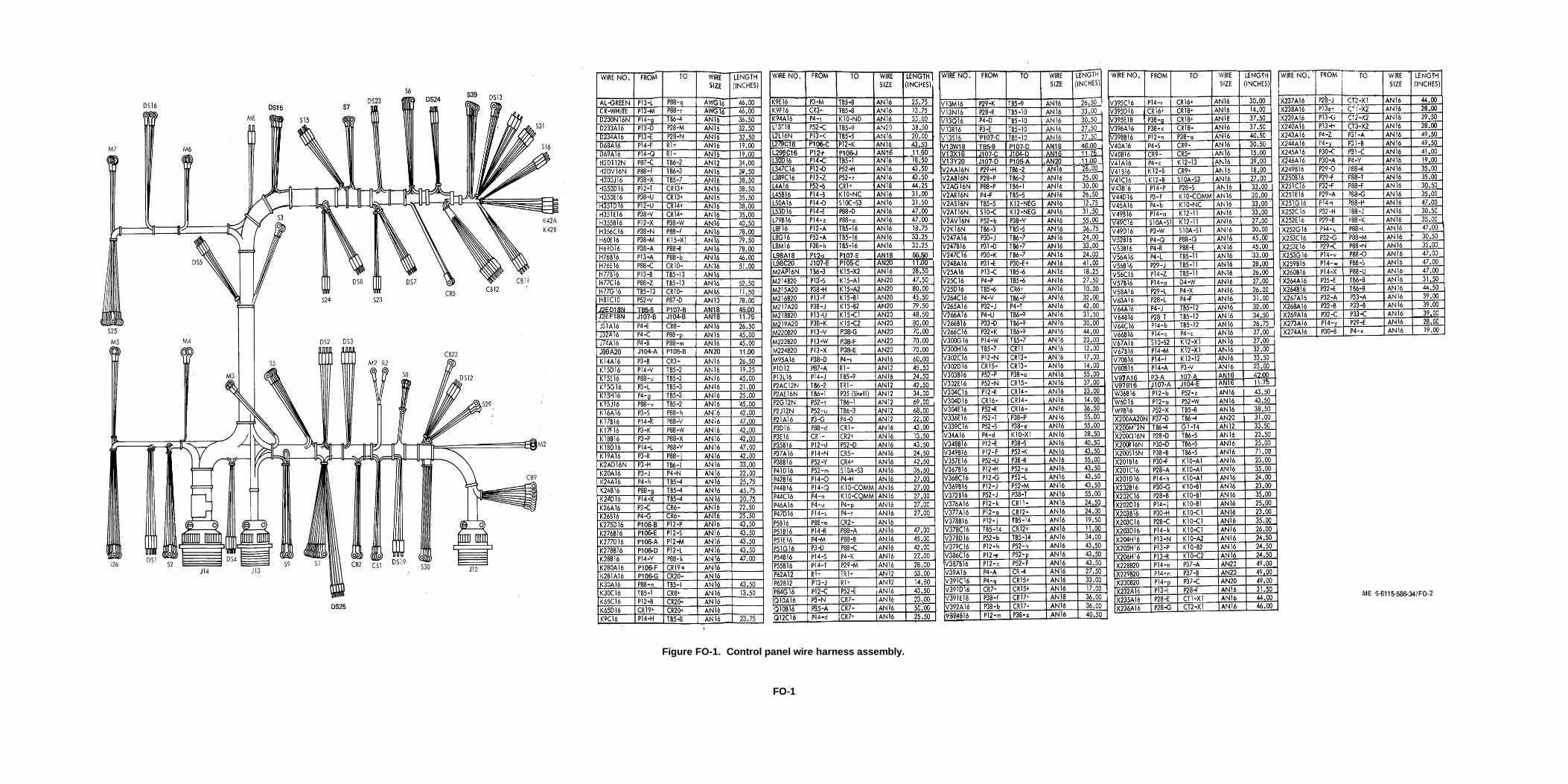
Figure FO-1. Control panel wire harness assembly.
FO-1
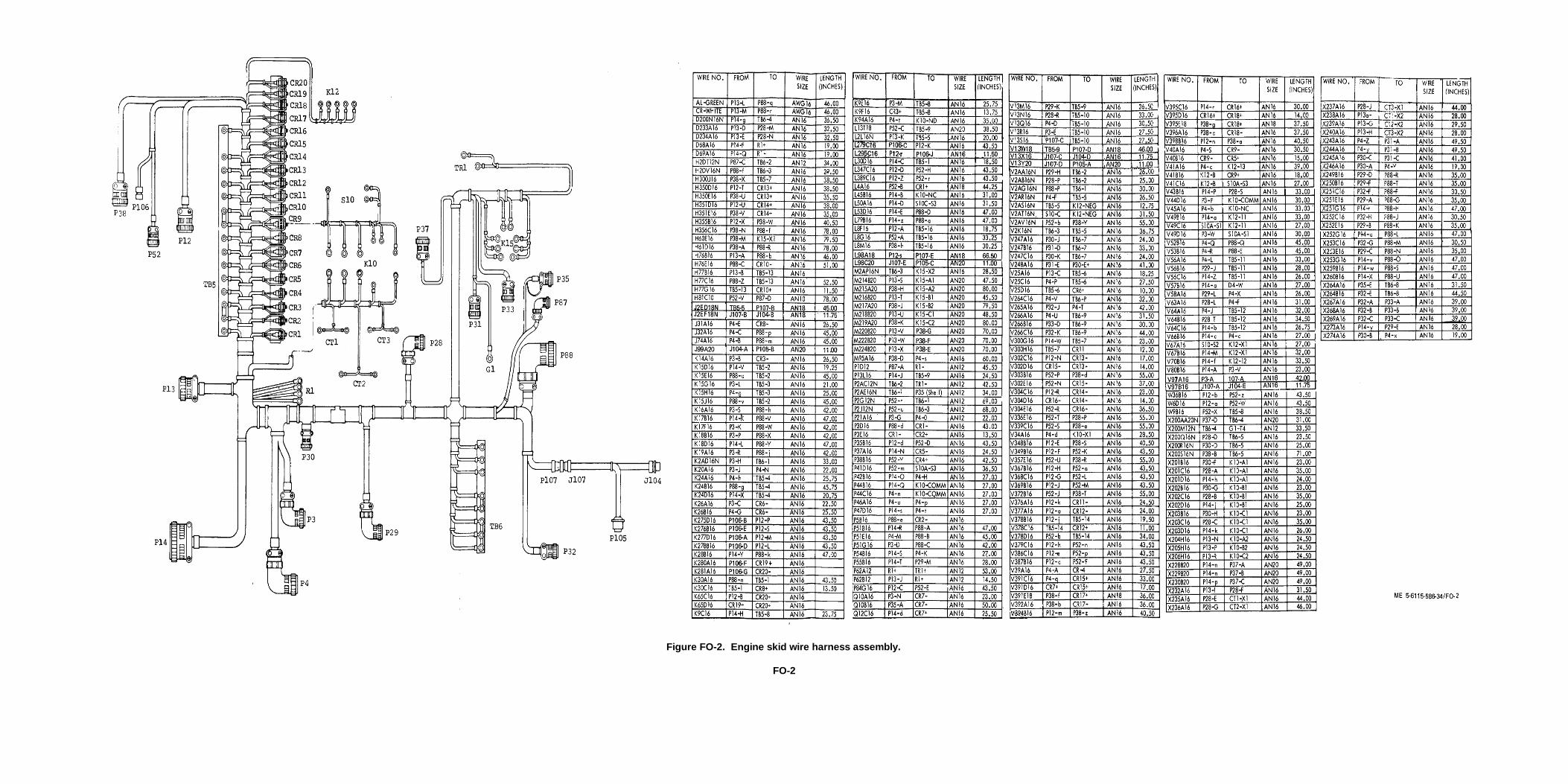
Figure FO-2. Engine skid wire harness assembly.
FO-2

PIN: 025693-000

This fine document...
Was brought to you by me:
Liberated Manuals -- free army and government manuals
Why do I do it? I am tired of sleazy CD-ROM sellers, who take publicly available information, slap “watermarks” and other junk on it, and sell it. Those masters of search engine manipulation make sure that their sites that sell free information, come up first in search engines. They did not create it... They did not even scan it... Why should they get your money? Why are not letting you give those free manuals to your friends?
I am setting this document FREE. This document was made by the US Government and is NOT protected by Copyright. Feel free to share, republish, sell and so on.
I am not asking you for donations, fees or handouts. If you can, please provide a link to liberatedmanuals.com, so that free manuals come up first in search engines:
<A HREF=http://www.liberatedmanuals.com/>Free Military and Government Manuals</A>
– SincerelyIgor Chudovhttp://igor.chudov.com/
– Chicago Machinery Movers


