Download - Td Operation Maintenance
EN/LZTBU 220 104/2 RC
UMUX from KEYMILE, covers all your communication requirements in one system.
Technical Description
UMUX Operation & Maintenance
UMUX/UCST R8
UMUX Operation & Maintenance System Release R8
Copyright and Confidentiality: Copyright in this document vests in Keymile AG (KEYMILE). This document contains confidential information which is the property of KEYMILE. It must be held in confidence by the recipient and may not be used for any purposes except those specifically authorised by contract or otherwise in writing by KEYMILE. This document may not be copied in whole or in part, or any of its contents disclosed by the recipient to any third party, without the prior written agreement of KEYMILE.
Disclaimer: KEYMILE has taken reasonable care in compiling this document, however KEYMILE accepts no liability whatsoever for any error or omission in the information contained herein and gives no other warranty or undertaking as to its accuracy. KEYMILE reserves the right to amend this document at any time without prior notice.
KEYMILE PEC: EN/LZTBU 220 104/2 RC
KEYMILE AG Schwarzenburgstrasse 73 CH-3097 Bern-Liebefeld Switzerland © April 2009 by KEYMILE AG
© KEYMILE AG
EN/LZTBU 220 104/2 RC Technical Description Systems iii
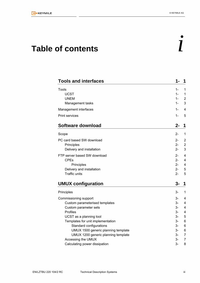
Table of contents i Tools and interfaces 1- 1
Tools 1- 1 UCST 1- 1 UNEM 1- 2 Management tasks 1- 3
Management interfaces 1- 4
Print services 1- 5
Software download 2- 1
Scope 2- 1
PC card based SW download 2- 2 Principles 2- 2 Delivery and installation 2- 3
FTP server based SW download 2- 4 CPEs 2- 4
Principles 2- 4 Delivery and installation 2- 5 Traffic units 2- 5
UMUX configuration 3- 1
Principles 3- 1
Commissioning support 3- 4 Custom parameterised templates 3- 4 Custom parameter sets 3- 4 Profiles 3- 4 UCST as a planning tool 3- 5 Templates for unit implementation 3- 6
Standard configurations 3- 6 UMUX 1500 generic planning template 3- 6 UMUX 1200 generic planning template 3- 7
Accessing the UMUX 3- 7 Calculating power dissipation 3- 8
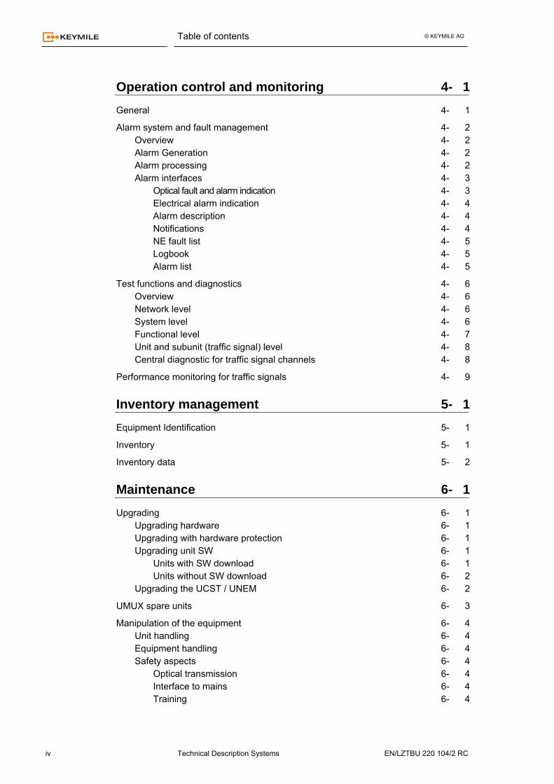
Table of contents © KEYMILE AG
iv Technical Description Systems EN/LZTBU 220 104/2 RC
Operation control and monitoring 4- 1
General 4- 1
Alarm system and fault management 4- 2 Overview 4- 2 Alarm Generation 4- 2 Alarm processing 4- 2 Alarm interfaces 4- 3
Optical fault and alarm indication 4- 3 Electrical alarm indication 4- 4 Alarm description 4- 4 Notifications 4- 4 NE fault list 4- 5 Logbook 4- 5 Alarm list 4- 5
Test functions and diagnostics 4- 6 Overview 4- 6 Network level 4- 6 System level 4- 6 Functional level 4- 7 Unit and subunit (traffic signal) level 4- 8 Central diagnostic for traffic signal channels 4- 8
Performance monitoring for traffic signals 4- 9
Inventory management 5- 1
Equipment Identification 5- 1
Inventory 5- 1
Inventory data 5- 2
Maintenance 6- 1
Upgrading 6- 1 Upgrading hardware 6- 1 Upgrading with hardware protection 6- 1 Upgrading unit SW 6- 1
Units with SW download 6- 1 Units without SW download 6- 2
Upgrading the UCST / UNEM 6- 2
UMUX spare units 6- 3
Manipulation of the equipment 6- 4 Unit handling 6- 4 Equipment handling 6- 4 Safety aspects 6- 4
Optical transmission 6- 4 Interface to mains 6- 4 Training 6- 4
Table of contents © KEYMILE AG
EN/LZTBU 220 104/2 RC Technical Description Systems v
Documentation and training 7- 1
Technical customer documentation 7- 1 Structure 7- 1 Document types 7- 1 Publication 7- 2
Technical customer training 7- 3
System labelling 7- 4 Identification label 7- 4
Identification label “Unit Hardware” 7- 4 Identification label “Function” level 7- 5
EMC and safety label ("CE" label) 7- 7 Location of "CE" label 7- 7 Limitation of liability 7- 7
Warning labels 7- 8 "Hazardous voltages" 7- 8 "Laser radiation" 7- 8 Electrostatic sensitive devices 7- 8
© KEYMILE AG
EN/LZTBU 220 104/2 RC Technical Description Systems vi
Precautions and safety
For generic information on precautions and safety refer to [033].
Referenced documents
[033] Precautions and safety [010] System Description UNEM (R8) [200] UMUX Technical Description (R8) [205] UMUX TDM Traffic System (R8) [206] UMUX ATM Traffic System (R8) [208] UMUX Operation & Maintenance (R8) [209] UMUX Management (R8) [210] UMUX Units (R8) [215] COBUX 212, 213, 219, 223 & COBUV 217, 218, 220, 224
Technical Description [053] Release Note UMUX / UCST [902] UMUX Network Functions User Guide (R8)
© KEYMILE AG
EN/LZTBU 220 104/2 RC Technical Description Systems 1-1
Tools and interfaces 1
Tools
• The UX platform provides the UCST and UNEM management tools for the UMUX
• Configuration • Operation control • Maintenance
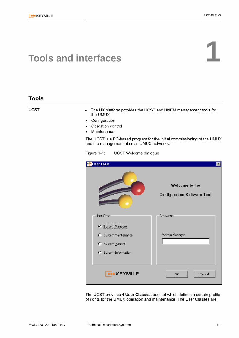
The UCST is a PC-based program for the initial commissioning of the UMUX and the management of small UMUX networks.
Figure 1-1: UCST Welcome dialogue
The UCST provides 4 User Classes, each of which defines a certain profile of rights for the UMUX operation and maintenance. The User Classes are:
UCST
Tools and interfaces © KEYMILE AG
1-2 Technical Description Systems EN/LZTBU 220 104/2 RC
• System Manager • System Maintenance • System Planner • System Information
The user classes (protection with a passwords is possible) allow you to con-trol the management access and to assign functional responsibilities. An ad-ditional asset of the user classes is the protection of the NEs and the net-work from unintentional interventions, which might create disturbances and service interruptions. The UNEM is a workstation-based element and network manager for me-dium size to big UMUX networks. The UNEM supports distributed manage-ment functions in a multi-user environment.
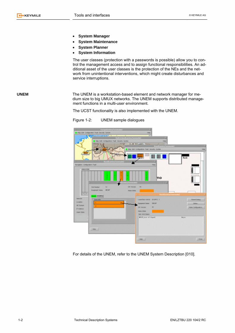
The UCST functionality is also implemented with the UNEM.
Figure 1-2: UNEM sample dialogues
For details of the UNEM, refer to the UNEM System Description [010].
UNEM
Tools and interfaces © KEYMILE AG
EN/LZTBU 220 104/2 RC Technical Description Systems 1-3
The UCST and UNEM access the UMUX (NE) for
• Configuration
• Inventory management
• Performance control and monitoring
• Fault management
• Test functions and diagnostics
The access to each UMUX is password protected (passwords are optional).
The UCST and UNEM provide each an appropriate GUI (Graphical User In-terface) for the configuration, control and monitoring of the above functions. Local functions on the units prepare and provide the local data for the UCST / UNEM.
Both managers can configure and manage the full range of the UMUX and DSL equipment.
For more information of the UCST / UNEM and corresponding access to the UMUX, refer to [209].
Management tasks
Tools and interfaces © KEYMILE AG
1-4 Technical Description Systems EN/LZTBU 220 104/2 RC
Management interfaces
The management access of the UCST and UNEM to the UMUX relies on 3 physical interfaces and, in UMUX networks, on the ECC which implements the Management Communication Network for UMUX.
Depending on the type of intervention and management infrastructure one of the 3 physical interfaces is used:
• F-interface for point-to-point access: Mainly used for local commissioning of the UMUX or for on site fault de-bugging via UCST. The F-interface allows bit-rates up to 115200 bit/s for local access (The speed available depends on the driver section of the PC/computer and the length of the signal cables).
The UCST / UNEM can also access the F-interface of the UMUX re-motely via a modem.
To connect to the UMUX via the F-interface, the NE node address (IP address) is required.
If required the F-interface can provide access to the EOC management communication channel. The bit-rate for EOC access is 9600 bit/s.
• QX-interface for Ethernet LAN access: The QX-interface is normally used for remote management access. How-ever, local commissioning via the QX-interface is possible, provided that your PC/computer features an Ethernet interface.
The UCST / UNEM addresses NEs (UMUX) that are connected with their QX-interface to a LAN. The UCST / UNEM can also access the ECC via the QX-interface. The QX-interface offers high bit-rates (10BaseT).
To connect to the NE, the UCST / UNEM needs to know the IP address of the QX-interface.
• Q1-interface for local clustering of the management access: The Q1-interfaces of several local NEs are connected in parallel to the 4-wires of the local Q-BUS. The Q-BUS is a serial bus and terminated to the UCST / UNEM or to the Q1-master interface of a UMUX.
The Q1-master interface directly drives the Q-BUS while the UCST / UNEM interface uses an external conversion box, which converts the Q-BUS to the standard RS-232C interface.
The UCST / UNEM accesses the NEs via its serial interface using HDLC addressing to select the NE on the Q-BUS, while the NE node address (IP address) is required for the connection.
The ECC structure implements the MCN (Management Communication Network) for UMUX in the network. The ECCs are transported in PDH, SDH and ATM based networks. COBUX and COBUV controlled UMUX have in-ternal interfaces for the ECC which are not directly accessible to the UCST and UNEM. The UCST and UNEM access the ECC via a UMUX which pro-vides the gateway to the ECC MCN (Management Communication Network) of the UMUX.
The COBUL and COBUQ control unit do not support the ECC functionality.
For a description of the UMUX management, refer to [209].
Tools and interfaces © KEYMILE AG
EN/LZTBU 220 104/2 RC Technical Description Systems 1-5
Print services
The UCST / UNEM provide several print services to print out formatted lists of the UMUX configuration and specific information on the performance of its traffic. The access to the print services depends on the type of information:
• A dedicated menu provides the print service for data based on configura-tion data (including alarm condition). This service allows you to print out formatted lists or to store the informa-tion to a file (*.CSV) for further processing.
• The print services for information based on dynamic data are directly ac-cessible in the dialogues providing the corresponding information. The in-formation is typically loaded with a GET command to the NE.
The UCST / UNEM allow you to print the following lists and data:
• Configuration based data − Units (slot, unit, short description of functions) − Unit parameters − Subunits − Alarm configuration − Cross connections − Timing sources
• Data based on dynamic processes − Logbook − Performance data − Inventory data − Alarm list (if NE polling is active)
Please note that any list like information presented in UCST dia-logues can be selected (via cursor) and copied to a text processing tool using the copy/paste function of Windows®.
This feature can be used to print the current "NE Fault List".

© KEYMILE AG
EN/LZTBU 220 104/2 RC Technical Description Systems 2-1
Software download 2
Scope
The service of a unit (with respect to traffic signals and the system) is called a FUNCTION and is defined by the unit hardware and the ESW.
Units with software download only feature bootloader software for the local microprocessor system in their on-board PROMs. All functionality specific software has to be downloaded to the local EPROM or RAM (the unit func-tion is only identified then!).
Units with SW download allow you to implement new Functions at any time by installing new unit software (ESW) on the unit if the existing hardware is compatible with the new ESW. Since the SW download uses the data com-munication network, it is possible to remotely update Functions.
The UMUX uses 2 basic types of software download for its units and sub-systems:
• PC card based SW download Most of the UMUX units and subsystems use this type of SW download. The SW download is fully UCST controlled and uses only resources of the UCST and UMUX. In the NE, all the ESW is intermediately stored in the PC memory card of the control unit for the subsequent distribution to the individual units and subsystems.
• FTP server based SW download The new generation of remote systems such as the MUSIC 700 use complex software systems that create huge amounts of program code (> 10 MB).
PC card based SW download is not suited to economically provide the required resources for the SW download to these CPEs. The SW is di-rectly downloaded from the FTP server to the CPE without immediate storage in the PC memory card of the control unit.
Software download © KEYMILE AG
2-2 Technical Description Systems EN/LZTBU 220 104/2 RC
PC card based SW download
The PC card based SW download is available for all the UMUX control units, the PBUS and the ABUS/PBUS units and some of the recently released UBUS units.
The PC card based SW download consists of 2 phases each phase with its own typical process:
• Software delivery • Software installation
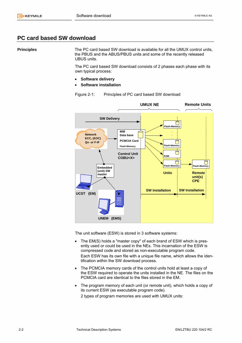
Figure 2-1: Principles of PC card based SW download
Control UnitCOBU<X>
MIBData base
PCMCIA Card
UNEM (EMS)
UCST (EM)
Flash-Memory
SW Delivery
Embedded(unit) SW master Units Remote
unit(s) CPE
UMUX NE
.
.
.
SW Installation
Remote Units
RAM
Flash-Memory Flash-Memory
Flash-Memory
Flash-Memory
SW Installation
Network ECC, (EOC)Qx- or F-IF
The unit software (ESW) is stored in 3 software systems:
• The EM(S) holds a "master copy" of each brand of ESW which is pres-ently used or could be used in the NEs. This incarnation of the ESW is compressed code and stored as non-executable program code. Each ESW has its own file with a unique file name, which allows the iden-tification within the SW download process.
• The PCMCIA memory cards of the control units hold at least a copy of the ESW required to operate the units installed in the NE. The files on the PCMCIA card are identical to the files stored in the EM.
• The program memory of each unit (or remote unit), which holds a copy of its current ESW (as executable program code). 2 types of program memories are used with UMUX units:
Principles
Software download © KEYMILE AG
EN/LZTBU 220 104/2 RC Technical Description Systems 2-3
− Non-volatile memories (Flash-Memories) The units with non-volatile program memories do not loose their ESW at power down. The configuration of the SW installation defines the appropriate ESW for the unit service.
− Volatile memories (RAMs) The units with volatile program memories lose their ESW at power down and require the re-installation of their ESW after each power up. The configuration of the SW installation guarantees this installation.
The COBU<X> features a flash memory for its own executable program code, which is downloaded from the PCMCIA card.
SW download for remote units (CPEs) requires corresponding units (host unit in the UMUX subrack and remote unit) and a control unit release ≥ R4.
With the UCST & UNEM R8 the following units support PC card based SW download for remote units
• LESI8 - MUSIC 200 • SLID1/2 - MUSIC 200
New CPEs are announced and will be introduced. The download of ESW is handled by 2 different system processes:
• SW delivery The SW delivery is the process, which transfers the compressed unit software from the EM to the PC memory card of the COBU<X> control unit. The software is stored as compressed program code in the PC memory card of the control unit.
The ESW can be provided via a local management interface or via a re-mote management channel. The delivery process is directly controlled by the EM and is not part of the configuration data of the NE.
• SW installation The SW installation is the local process in the NE, which decompresses the ESW on the PC memory card and copies the code to the individual units.
The ESW for remote units (CPEs) is decompressed and loaded into a temporary buffer of the host UMUX unit. At the time of SW installation, the ESW is loaded to the remote unit and installed in the remote unit.
You can define the SW installation independently for the local and the remote units (providing they are compatible).
It is possible to assign different versions of ESW to identical units (as-suming compatibility between hardware and software).
The SW installation is a part of the NE configuration. The installation of software is successful only, if the required ESW is locally available on the PC memory card. To satisfy this requirement you have to deliver the cor-responding ESW before you configure the installation of the ESW.
A unit without ESW does not operate. It will be signalled as a unit hardware failure! In any case, the PC memory card has to hold copies of at least one ESW for control units and the application download SW. A control unit with-out this minimum SW cannot operate or load ESW and will be seen as "unit failure". This state is indicated by a permanently active red unit LED.
Delivery and installation
Software download © KEYMILE AG
2-4 Technical Description Systems EN/LZTBU 220 104/2 RC
FTP server based SW download
The FTP server based SW download uses an external FTP server and is available for CPEs with large program codes such as the MUSIC 700 family products.
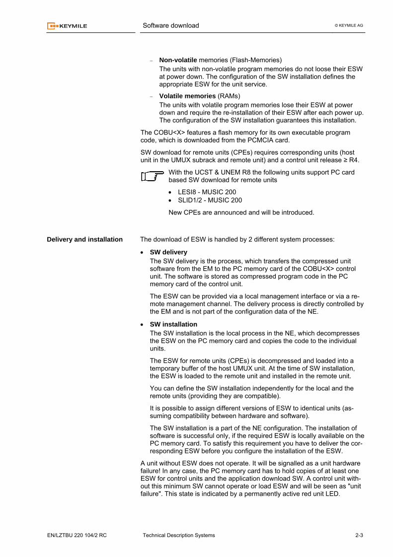
Figure 2-2: Principles of the FTP sever based SW download
RemoteCPE
DSL IF
Flash-Memory
UMUX
10/100BaseT
SW Update files for CPE
FTP server
DSL IF
Ethernet IF
MUSIC 700
Ethernet IF
UMUX
Pair
A
B
B
B
UNEM (EMS)
UCST (EM)
NetworkECC, (EOC)Qx- or F-IF
The ESW for the CPE is stored on the FTP server. The new SW is downloaded from the FTP server to the CPE via any of the following 2 ways (refer to the figure above):
A From the FTP server via the IP network (if applicable) and the local LAN (10/100BaseT) the SW is downloaded through the Ethernet inter-face of the unit to the CPE.
B From the FTP server via the IP network (if applicable) and a LAN in-terface of the UMUX (e.g. LAWA4) the SW is routed into the UMUX network. The SW is downloaded from the UMUX with the hosting DSL line interface unit via the DSL link to the CPE.
With the UCST, you must route the path for the SW download from the FTP server through the UMUX network to the CPE.
For both methods, the UCST configures the CPE for the SW download and controls the SW download. It is possible to configure the SW download for immediate application or schedule the application of the new SW for a later time.
You need a high capacity data communication channel between your FTP server and the CPE to keep the download time reasonably short. Accord-
CPEs Principles
Software download © KEYMILE AG
EN/LZTBU 220 104/2 RC Technical Description Systems 2-5
ingly, the UMUX management communication network is not suited for FTP server based SW download.
If you want to download the SW via the DSL link to the CPE, you must con-figure the corresponding data path from the FTP server to the CPE. Depend-ing on the complexity of your access network, this task requires some con-figuration effort and uses capacity in your access network.
With the UCST & UNEM R8 and the release R4/5 control units the following units/CPE systems support FTP server based SW download for CPE!
• LESI8 - MUSIC 703 λ / 710 λ / 711λ • SLID1/2 - MUSIC 703 λ / 710 λ / 711λ
Delivery and installation of the ESW is CPE specific. The description of these processes is beyond the scope of this document.
For detailed information on the process for the delivery and installation of new ESW for CPEs, refer to the User Guide of the corresponding unit For selected units, the software download for the unit software (ESW) is not integrated into the standard management concept for UMUX ESW. This applies for traffic units with particularly bulk ESW where the download via the COBU<X> exceeds the capacity of the local resources.
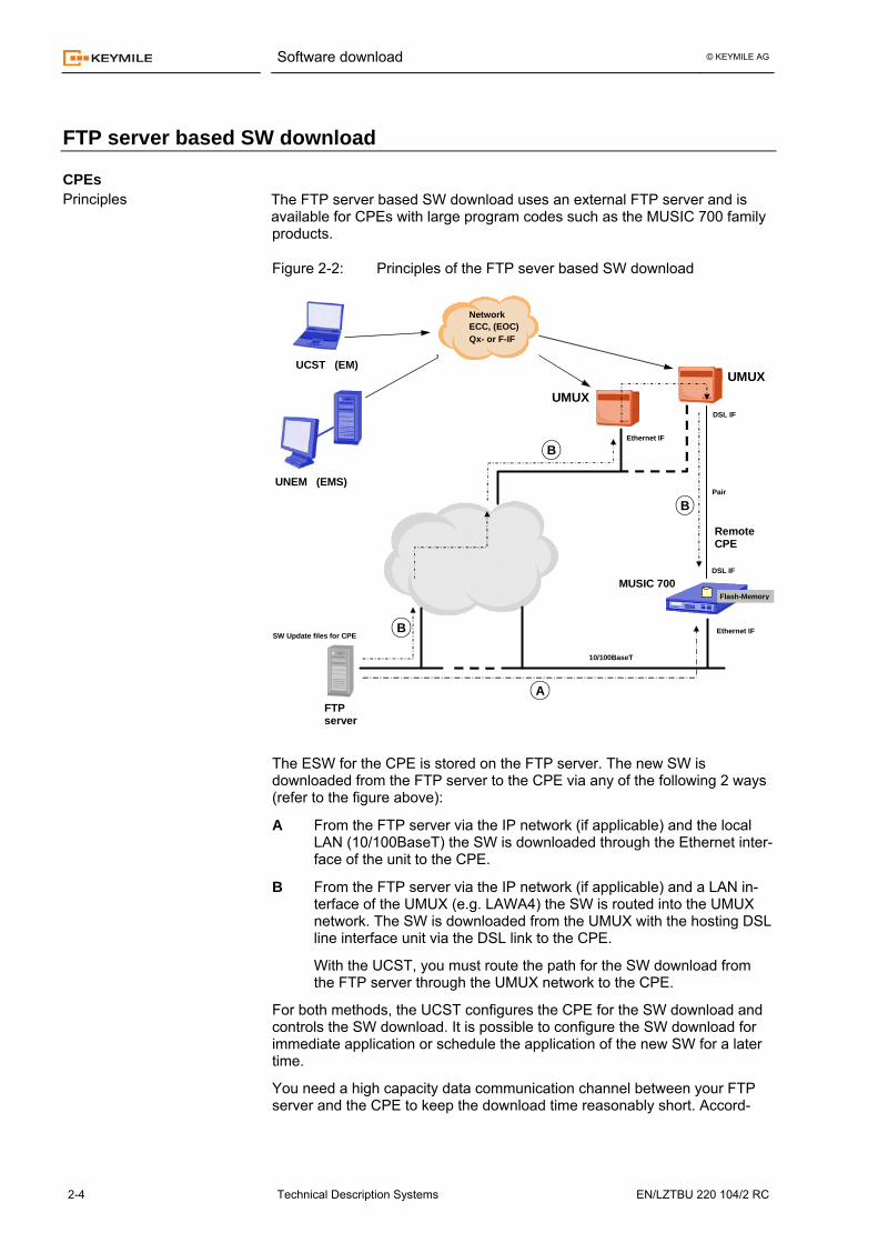
The figure below shows the download path for ESW to the IPLM<x> units.
Figure 2-3: Logical view of the IPLM<x> management concept
Telnet
launch
UMUX 1500 / 1200 with COBUX/COBUV and IPLM<x> cluster
KEYMILE UCST
KEYMILE UNEM
IPLM<x> CLI
TFTP file server For configuration-
and ESW download
The Keymile UCST has direct access to the management network parame-ters on the IPLM<x> (see below). This is necessary to establish IP connec-tivity to the IPLM<x> in order to launch a telnet session.
A dedicated process allows downloading the ESW from the FTP server un-der the control of the IPLM CLI.
Delivery and installation
Traffic units

© KEYMILE AG
EN/LZTBU 220 104/2 RC Technical Description Systems 3-1
UMUX configuration 3
Principles
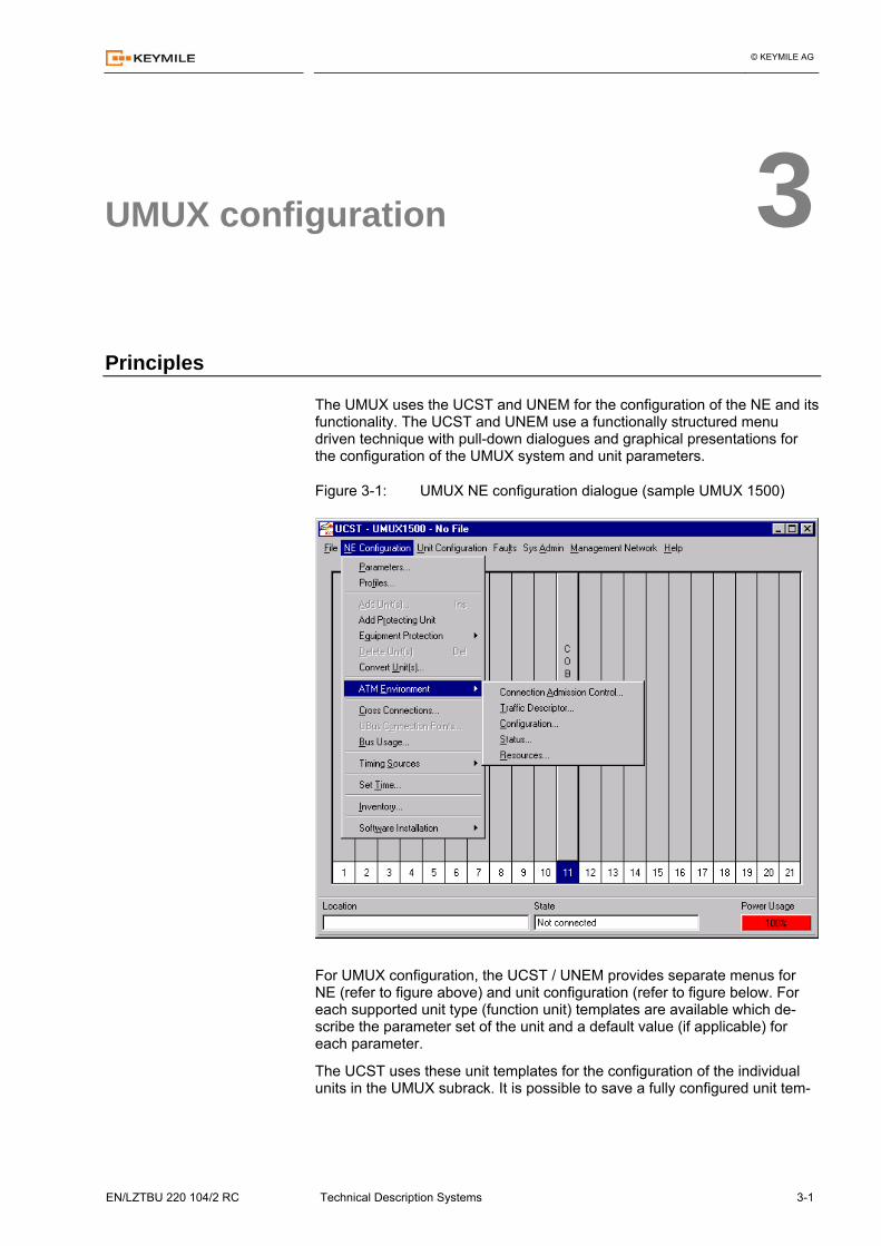
The UMUX uses the UCST and UNEM for the configuration of the NE and its functionality. The UCST and UNEM use a functionally structured menu driven technique with pull-down dialogues and graphical presentations for the configuration of the UMUX system and unit parameters.
Figure 3-1: UMUX NE configuration dialogue (sample UMUX 1500)
For UMUX configuration, the UCST / UNEM provides separate menus for NE (refer to figure above) and unit configuration (refer to figure below. For each supported unit type (function unit) templates are available which de-scribe the parameter set of the unit and a default value (if applicable) for each parameter.
The UCST uses these unit templates for the configuration of the individual units in the UMUX subrack. It is possible to save a fully configured unit tem-
UMUX configuration © KEYMILE AG
3-2 Technical Description Systems EN/LZTBU 220 104/2 RC
plate as an application (customer) specific unit template for the fast configu-ration for this unit type.
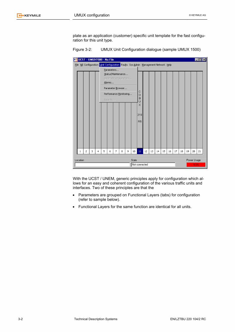
Figure 3-2: UMUX Unit Configuration dialogue (sample UMUX 1500)
With the UCST / UNEM, generic principles apply for configuration which al-lows for an easy and coherent configuration of the various traffic units and interfaces. Two of these principles are that the
• Parameters are grouped on Functional Layers (tabs) for configuration (refer to sample below).
• Functional Layers for the same function are identical for all units.
UMUX configuration © KEYMILE AG
EN/LZTBU 220 104/2 RC Technical Description Systems 3-3
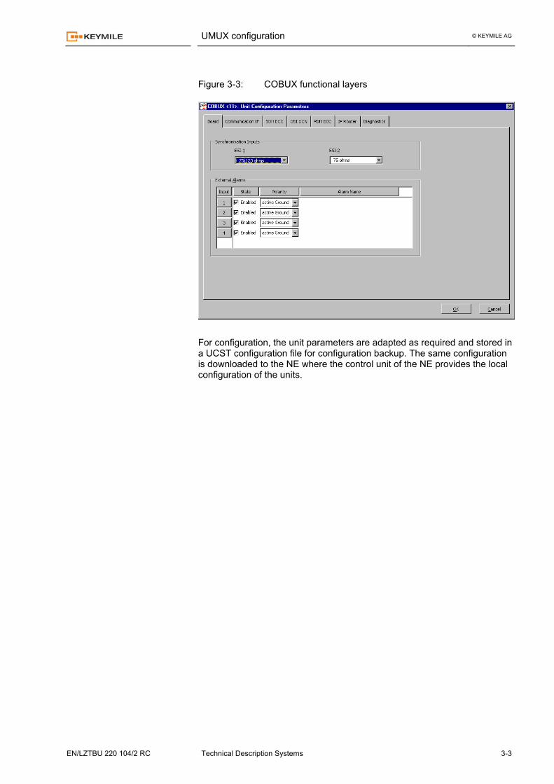
Figure 3-3: COBUX functional layers
For configuration, the unit parameters are adapted as required and stored in a UCST configuration file for configuration backup. The same configuration is downloaded to the NE where the control unit of the NE provides the local configuration of the units.
UMUX configuration © KEYMILE AG
3-4 Technical Description Systems EN/LZTBU 220 104/2 RC
Commissioning support
To support the frequent configuration of a (function) unit type with identical or very similar parameters it is possible to save a fully configured unit template as a new type of (function) unit. To allow a fast and reliable commissioning of the UMUX for frequent applica-tions with high volumes of UMUX Access Systems, it is possible to create custom parameter sets for several of the functions of the UMUX.
The custom parameters are integrated as sets of parameters into a corre-sponding database of the UCST / UNEM software. Each set has its unique identifier. You cannot subsequently modify individual parameters of a set. The selection of the appropriate custom parameter set from the database al-lows you e.g. to pre-set fast and reliably several hundreds of parameters that are required for the operation of the V5.x interface.
The UCST R8 defines several parameters sets for the following functions:
• V5.x application • Telephony NGN application (H.248/MEGACO and RTP protocol imple-
mentation and traffic related parameters) • SUBH<X>, PHLC<X> PSTN and line test functions
The UCST / UNEM uses the custom parameters to properly initialise the templates of the units implied with the corresponding function. Today both functions mentioned above are integrated within one type of sets. The prin-ciple of custom parameter sets will be expanded as required with new sets, new functions and new types of sets. Profiles are introduced to simplify the procedure for configuring many sub-units (generally speaking: configuration entities) with an identical set of pa-rameters across an entire UMUX network.
Profiles are typically used for service configuration in networks. The profiles contain all the parameters that are required to configure corresponding units for a service. A typical example for such service configuration is the ADSL profile.
Profiles are predefined structures with a defined subset of parameters for functions of units. The UNEM / UCST can offer profile types for different con-figuration entities with given structures. The operator cannot create or mod-ify the profile structure. Only the values of the parameters the profile con-tains can be selected. Each profile type has its default profile (shaded grey in the diagram below, e.g. 1st line).
Profiles are handled on 2 levels
• EM (UCST and UNEM) A profile can be created via the UNEM and is then stored in its database. It can be called upon when configuring any configuration entity of this type (e.g. any ADSL port) in any UMUX controlled by that UNEM.
A profile can also be created using the UCST in a local connection to a UMUX. In that case it will be stored locally in the file system of UCST.
Custom parameterised templates
Custom parameter sets
Profiles
UMUX configuration © KEYMILE AG
EN/LZTBU 220 104/2 RC Technical Description Systems 3-5
• NE (UMUX) Application of the profile parameters in the NE (UMUX units)
With the UCST R8, only profiles of the type ADSL are available. The profiles are used with the ADACA and ADACB are available.
It is panned to expand the profile concept for new parameters. New profiles will be provided with Service Packs and new UCST releases. The UCST provides an efficient means to continuously check your unit con-figuration in the UMUX subrack.
The UCST "knows" most of the rules of unit implementation and helps you to avoid illegal configurations. The UCST also provides information on the con-verted power available and the requirements for converted power in the subrack.
Design the configuration of units in your subrack with the UCST/UNEM (e.g. in a standalone session) before you implement the units in the subrack. This helps to avoid problems of configuration coming up during commissioning.
The UCST/UNEM supports network wide configurations with
• Customer created configuration templates for units These configurations are saved under customer defined names and are used for the rapid configuration of units with identical parameters.
• Profiles Profiles are predefined structures with a defined subset of parameters for functions of units. The UCST/UNEM can offer profile types for different configuration entities with given structures. A typical example for such service configuration is the ADSL profile.
Several iterations might be necessary to find the most appropriate configura-tion for given requirements.
UCST as a planning tool
UMUX configuration © KEYMILE AG
3-6 Technical Description Systems EN/LZTBU 220 104/2 RC
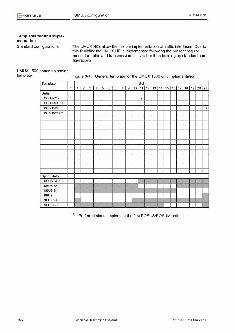
The UMUX NEs allow the flexible implementation of traffic interfaces. Due to this flexibility the UMUX NE is implemented following the present require-ments for traffic and transmission units rather than building up standard con-figurations. Figure 3-4: Generic template for the UMUX 1500 unit implementation
Template Slot m 1 2 3 4 5 6 7 8 9 10 11 12 13 14 15 16 17 18 19 20 21Units
COBU<X> 1 X COBU<X> 1+1 POSUS/M 1)POSUS/M n+1
Spare slots
UBUS S1,2 UBUS S3 UBUS S4 PBUS SBUS SA SBUS SB
1) Preferred slot to implement the first POSUS/POSUM unit.
Templates for unit imple-mentation Standard configurations
UMUX 1500 generic planning template
UMUX configuration © KEYMILE AG
EN/LZTBU 220 104/2 RC Technical Description Systems 3-7
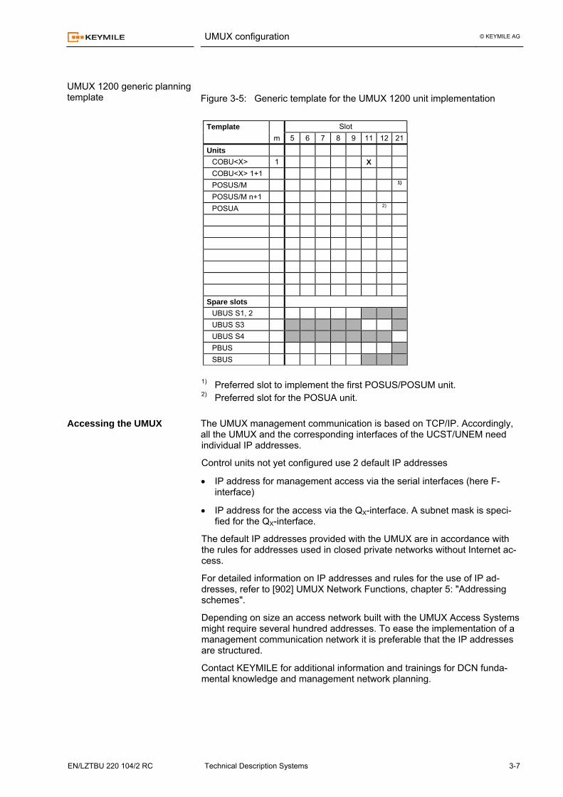
Figure 3-5: Generic template for the UMUX 1200 unit implementation
Template Slot m 5 6 7 8 9 11 12 21 Units
COBU<X> 1 X COBU<X> 1+1 POSUS/M 1)
POSUS/M n+1 POSUA 2)
Spare slots
UBUS S1, 2 UBUS S3 UBUS S4 PBUS SBUS
1) Preferred slot to implement the first POSUS/POSUM unit. 2) Preferred slot for the POSUA unit. The UMUX management communication is based on TCP/IP. Accordingly, all the UMUX and the corresponding interfaces of the UCST/UNEM need individual IP addresses.
Control units not yet configured use 2 default IP addresses
• IP address for management access via the serial interfaces (here F-interface)
• IP address for the access via the QX-interface. A subnet mask is speci-fied for the QX-interface.
The default IP addresses provided with the UMUX are in accordance with the rules for addresses used in closed private networks without Internet ac-cess.
For detailed information on IP addresses and rules for the use of IP ad-dresses, refer to [902] UMUX Network Functions, chapter 5: "Addressing schemes".
Depending on size an access network built with the UMUX Access Systems might require several hundred addresses. To ease the implementation of a management communication network it is preferable that the IP addresses are structured.
Contact KEYMILE for additional information and trainings for DCN funda-mental knowledge and management network planning.
UMUX 1200 generic planning template
Accessing the UMUX
UMUX configuration © KEYMILE AG
3-8 Technical Description Systems EN/LZTBU 220 104/2 RC
While the theoretical maximum power dissipation in a subrack is straightfor-ward to calculate, it is not easy to estimate the mean power dissipated in a UMUX subrack. The power dissipation depends heavily on the type of units implemented and the traffic load. There are 2 ways to approach the mean power dissipation of the UMUX, via the theoretical maximum power dissipation or via summing the power dissi-pation of units under real traffic load.
• Theoretical maximum power dissipation The theoretical maximum dissipation is evaluated by summing the maxi-mum power consumption at the external power supply interface of the UMUX. It is assumed that all energy is dissipated within the subrack. This value is easy to calculate but provides a worst case value which is, depending on units and traffic, far above the real mean power dissipation. − The evaluation of the mean power dissipation according to this
method however provides reasonable results for the mean power dissipation if the UMUX operates as - Cross connect - Access System for data interfaces
(no remote data units) − Channel banks with exchange line interfaces
(no ground keys)
− The method is not suited to estimating the mean power dissipation if a considerable part of the energy provided via the power interface of the UMUX is dissipated in equipment external to the NE. This applies for the following applications: − Access System for data interfaces with remote data units
including ISDN (remote powering)
- applications with V5.x/NGN User Ports including ISDN (remote powering)
- applications with SUBLA<X> and SUBH<X>/PHLC<X> units (subscriber loops)
− channel banks with subscriber line interfaces
In the latter cases, you can estimate the mean power dissipation as de-scribed below.
• Estimated mean power dissipation The estimated mean power dissipation is calculated in 2 steps:
− Evaluation of the theoretical maximum power dissipation for - Control units - Power supply units - Transmission units − etc.
− Summing of the power dissipation of the remaining units for a speci-fied operation mode and traffic load. Values depending on traffic load and the mode of operation are pro-vided with the technical specifications in the unit technical descriptions (e.g. for the SUBH<X> and PHLC<X>).
The estimated mean power dissipation in the subrack is the total sum of all units.
Calculating power dissipa-tion
© KEYMILE AG
EN/LZTBU 220 104/2 RC Technical Description Systems 4-1
Operation control and monitoring 4
General
Performance control and monitoring is the enveloping process for all the control of system performance and monitoring of traffic performance.
According to this definition, the UMUX provides the following functions and subsystems for performance control and monitoring:
• Alarm system The alarm system is an important function of the UMUX and is described with its alarm interfaces in a separate paragraph in this chapter.
• Test functions and diagnostics Separate paragraphs in this chapter are dedicated to the test and diag-nostic functions provided with the UMUX.
• Traffic signal performance monitoring Performance monitoring for traffic signals is a generic function for all types of traffic processed in the UMUX. A paragraph at the end of this chapter provides a short overview of this functionality.
Operation control and monitoring © KEYMILE AG
4-2 Technical Description Systems EN/LZTBU 220 104/2 RC
Alarm system and fault management
The UMUX fault management detects equipment, function and transmission failures, or more generally, monitors the availability of the equipment and transmission paths. This includes an alarm system with various interfaces for the indication of faults and failures. These interfaces include local alarm indication and, depending on configured options, entries in the alarm list and/or the logbook.
Please note that the following description relies on the terms fail-ure, defect, degradation, fault etc. to distinguish between the dif-ferent levels in the alarm processing.
Each unit of the UMUX is able to detect equipment and/or traffic related de-fects and anomalies. For further processing, these defects or anomalies are transformed into fault causes. For each of the fault causes you can set a re-porting option (via the UCST / UNEM) which enable (MON) or block (NMON) the further processing of the fault causes. Only fault causes with the report-ing option set to MON will be considered for further processing. Faults with the option set to NMON will not be considered.
Setting the reporting option to NMON is useful for interfaces without traffic and prevents the generation of useless alarms during commissioning and maintenance.
A fault cause is declared a failure if the fault cause persists for a certain time, called the persistence time. The failure is cleared if the fault cause is absent for a certain time, called the absent time. You can set persistence time and absence time individually per fault cause. Based on detected defects (AIS, LOS and LOF), the NE can initiate other consequent actions, such as 1+1 protection switching. The UMUX is able to store time stamped information on events, failures and notifications in a log-book. The COBU<X> control unit creates the logbook locally. It is possible to transfer the contents of the logbook and the pending alarms of the NE to the UCST / UNEM for display and inspection.
Alarms are generated based on failures. For each fault cause one out of the three severities can be assigned:
• „logbook only“ • „non urgent“ alarm (NA) • „urgent“ alarm (UA)
An alarm or entry to the logbook is created only if the MON option is on. If the severity is set to „non urgent“ or „urgent“ alarm, the alarm indicator LEDs on the front panel of the control unit are activated/deactivated and the alarm relay contacts are switched over correspondingly. A yellow LED is used to indicate a non urgent alarm, and a red LED is used to indicate an urgent alarm. If the severity is set to „logbook only“, an entry to logbook is created but no alarm is generated.
All unit failures and anomalies are signalled via the local fault indication LED on the front panel of the affected unit(s).
Overview
Alarm Generation
Alarm processing
Operation control and monitoring © KEYMILE AG
EN/LZTBU 220 104/2 RC Technical Description Systems 4-3
Traffic related fault causes are processed similarly. The traffic failure LED on each unit is activated for all traffic failures set to MON. The generation of alarms and logbook entries are handled the same way as unit faults.
The actual alarm condition and the logbook can be loaded for display and inspection to the UCST / UNEM at any time. The Alarm List available with the UNEM and UCST polling (for up to 30 NEs only) shows the current alarm state for the polled NEs i.e. the access network. A dedicated LED indicator signals faults of unit hardware or failures of func-tions on each unit. This fault signalling is independent of the generation of alarms.
Units with interfaces for traffic signals provide an second LED indicator which signals a degradation of the quality of the traffic signals connected to the unit.
Additional alarm indicator LEDs implemented on the control unit show the pre-sent state of alarms (UA, NA) on the NE level. Simultaneously 2 changeover re-lay contacts signal the alarm state for external alarm state processing. Optical fault indications are implemented on both "system" and "unit" level. Alarms are concentrated on system level to "Urgent alarms" (UA) and "Non-urgent Alarms" (NUA). The present system alarm state is optically indicated with corresponding LEDs implemented on the COBU<X> unit.
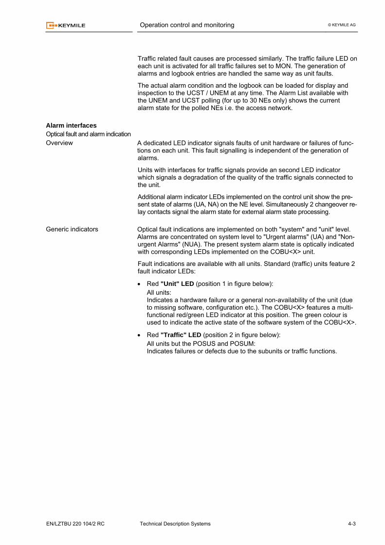
Fault indications are available with all units. Standard (traffic) units feature 2 fault indicator LEDs:
• Red "Unit" LED (position 1 in figure below): All units: Indicates a hardware failure or a general non-availability of the unit (due to missing software, configuration etc.). The COBU<X> features a multi-functional red/green LED indicator at this position. The green colour is used to indicate the active state of the software system of the COBU<X>.
• Red "Traffic" LED (position 2 in figure below): All units but the POSUS and POSUM: Indicates failures or defects due to the subunits or traffic functions.
Alarm interfaces Optical fault and alarm indication Overview
Generic indicators
Operation control and monitoring © KEYMILE AG
4-4 Technical Description Systems EN/LZTBU 220 104/2 RC
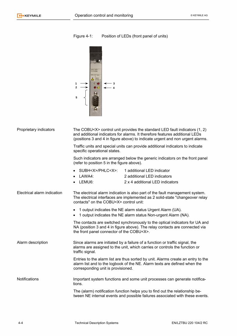
Figure 4-1: Position of LEDs (front panel of units)
12 4
3
5
The COBU<X> control unit provides the standard LED fault indicators (1, 2) and additional indicators for alarms. It therefore features additional LEDs (positions 3 and 4 in figure above) to indicate urgent and non urgent alarms.
Traffic units and special units can provide additional indicators to indicate specific operational states.
Such indicators are arranged below the generic indicators on the front panel (refer to position 5 in the figure above).
• SUBH<X>/PHLC<X>: 1 additional LED indicator • LAWA4: 2 additional LED indicators • LEMU6: 2 x 4 additional LED indicators The electrical alarm indication is also part of the fault management system. The electrical interfaces are implemented as 2 solid-state "changeover relay contacts" on the COBU<X> control unit:
• 1 output indicates the NE alarm status Urgent Alarm (UA). • 1 output indicates the NE alarm status Non-urgent Alarm (NA).
The contacts are switched synchronously to the optical indicators for UA and NA (position 3 and 4 in figure above). The relay contacts are connected via the front panel connector of the COBU<X>. Since alarms are initiated by a failure of a function or traffic signal, the alarms are assigned to the unit, which carries or controls the function or traffic signal.
Entries to the alarm list are thus sorted by unit. Alarms create an entry to the alarm list and to the logbook of the NE. Alarm texts are defined when the corresponding unit is provisioned. Important system functions and some unit processes can generate notifica-tions.
The (alarm) notification function helps you to find out the relationship be-tween NE internal events and possible failures associated with these events.
Proprietary indicators
Electrical alarm indication
Alarm description
Notifications
Operation control and monitoring © KEYMILE AG
EN/LZTBU 220 104/2 RC Technical Description Systems 4-5
Notifications create an entry in the logbook of the NE. The NE fault list is a structured list of pending faults (generating alarms) sorted by units and subunits. Each fault entry contains a short fault (alarm) description. The alarm status at system level is indicated as well.
The list of faults (alarm list) can be loaded to the UCST / UNEM for detailed inspection and printed for documentation. The logbook is an internal buffer of the COBU<X> containing a log of inci-dents with time stamps (the term “incident” is used here instead of “event” to distinguish “incidents” from “incidents” of the “event” type). In addition to the time stamps, the logbook shows the information and state for each incident. The following incidents create entries in the logbook:
• State change to active failure for fault causes monitored for alarms (MON = alarms) or for entries to the logbook only (MON = logbook only).
• The state change to inactive failure for fault causes monitored for alarms (MON = alarms) or for entries to the logbook only (MON = logbook only).
• Events Entries of the type "Event" are incidents which do not create alarms, but are logged for debugging and tracing important manipulations (incidents) on the NE. An important source for “Event” type incidents is the software system of the NE.
The logbook can be loaded to the UCST / UNEM for detailed inspection and printed for documentation. The Alarm List is available with the UNEM and is a new feature for UCST releases ≥ R5B which support NE polling. While the number of polled NEs is almost open for the UNEM, the UCST allows you to poll a network of up to 30 NEs and generate the collective Alarm List for these NEs.
The Alarm List shows coloured alarms and corresponding state information to indicate the current alarm states. It is possible to acknowledge alarms in the alarm list.
NE fault list
Logbook
Alarm list
Operation control and monitoring © KEYMILE AG
4-6 Technical Description Systems EN/LZTBU 220 104/2 RC
Test functions and diagnostics
The UMUX provides diagnostics and test functions, which allow active test-ing of functional blocks, important functions, selected hardware items and traffic signals.
Test functions and diagnostics provided are available on the
• Network level • System level • Functional level • Unit and subunits (traffic level) • Central diagnostics
You can control the diagnostic and test functions with the UCST / UNEM via the menus Status/Maintenance and Diagnostics Parameters respectively, depending on the level (system, function, unit) and the type of diagnostics. For some of the functions the dialogues for the function's configuration pro-vide “Diagnostic” buttons to verify the configuration.
The diagnostic and test functions do not generally belong to the configura-tion management. The corresponding settings are therefore not part of the configuration data. The functions can be controlled only when the UCST / UNEM is connected to the NE. All test settings get lost with the loss of power or a system reset. In addition to the test and diagnostic functions on the system level (refer to the paragraph below) the UNEM provides the
• Alarm List with Filters The alarm list shows coloured alarms and corresponding state informa-tion to indicate the current alarm states. Filters allow you to select alarm categories and sources.
• Synchronisation Map The synchronisation map function shows the flow of synchronisation sig-nals and helps you to identify synchronisation loops.
• Activity List and Event Log History The activity list records all management related activities of the UNEM and stores the events in the event log history file. This allows you among other to identify NEs with management communication problems.
for diagnostics on the network level.
The UCST polling function (UCST releases ≥ R5B) can create the NE Alarm List for small networks with up to 30 NEs. However, filters are not available with the UCST polling. On the system level, test and diagnostic functions are provided as follows:
• Alarm indicators LED indicators for urgent and non urgent alarms including associated switchover relay contacts.
Overview
Network level
System level
Operation control and monitoring © KEYMILE AG
EN/LZTBU 220 104/2 RC Technical Description Systems 4-7
• NE fault list Time stamped entries of all pending alarms
• Logbook The logbook is a list with chronological time stamps and descriptive text for each alarm. The logbook contains an entry for the time the alarm comes up and the time the alarm disappears. Events and notifications create additional entries.
• Inventory management Inventory provides access to the inventory data of each unit and the re-lated information on the MIB of the NE. Inventory is particularly powerful, for trouble shooting and questions of compatibility.
Dedicated dialogues provide the access for the UCST / UNEM to the differ-ent lists, the logbook and the inventory data. On the functional level, test and diagnostic functions are provided as follows:
• Diagnostics for PETS, SETS and ESO SDH informs you of the availability of the configured timing sources. For diag-nostic purposes, the UCST provides the dedicated status menu. The status menu allows the analysis of the timing system of the NE. Control functions allow you to force the system to synchronise to selected timing sources, overriding the automatic source selection. It is also possible to lock out a particular timing source from the selection process.
• Diagnostic function for protected cross connections informs you of your presently active signal path and the quality of the cor-responding tributary signal.
• Information on the usage of UBUS and PBUS informs you of your present use of the UBUS and PBUS. The diagnostic provides details of the connection points on the UBUS and the remaining capacity on the UBUS and PBUS.
• State indication and diagnostics for unit equipment protection − System control (COBU<X>)
informs you of your presently active control unit and the state of the MIB of the standby unit. Switching to the inactive control unit can be forced (if unit available).
− N+1 equipment protection of traffic units informs you of the presently active traffic units and the standby unit in the equipment protection group. Switching to the standby traffic unit can be forced.
N+1 equipment protection is only available for selected traffic units. N+1 equipment protection is only available for units without front inter-faces und homogeneous bus access.
• State indication and diagnostics for software download and installa-tion allows you to control the parameters of your NE software installation and to monitor the SW installation process for the units of the NE.
Functional level
Operation control and monitoring © KEYMILE AG
4-8 Technical Description Systems EN/LZTBU 220 104/2 RC
• State indication and diagnostics for the ECC OSPF router − Routing table of the local OSPF router. − IP statistics reflecting the activities and traffic on the respective router
interfaces. − OSPF link state and neighbour tables.
• State indication and diagnostics for ECC links informs you of the availability of configured ECCs.
Access to all functions is with the UCST / UNEM. Most of these functions (exceptions are diagnostics of synchronisation and cross connections, equipment protection for units) are accessed via the “Status” menu of the COBU<X> control unit. On the unit and subunit (traffic signal) level test and diagnostic functions are provided as follows:
• Fault indicators of units Optical indicators for the physical localisation of unit and traffic failures.
• Test loops Most of the traffic units feature points within the traffic signal path for the application of test loops. Test loops might be set as front end (towards the traffic interface) or back end (towards the cross connect) loops. Test loops are helpful tools for the detection of equipment and/or transmission faults.
• State indication for traffic signals Read back of signalling and TS 0 Sa-bit information. If applicable the trail identifier received is displayed as well.
• Central diagnostics for traffic signal channels For details, refer to paragraphs below.
• Performance monitoring A description of performance monitoring for traffic signals is provided in the paragraphs on “Redundancy and protection” in the chapter 3 “Func-tional Descriptions”.
• Subscriber line test The PBUS units with PSTN subscriber line interfaces feature built-in test facilities to test subscriber lines (SUBH<X>, PHLC<X>). The test can be programmed for automatic execution.
Most of these functions (exceptions are optical indicators) are accessed with the UCST / UNEM via “Status” or “Diagnostic” menus.
For details, refer to the respective unit descriptions. The COBUV and COBUX control units provide versatile diagnostic functions for the analysis of the performance of data channels set up between two access points. The access points are defined as the interfaces to a test sig-nal generator and a signal analyser. Both functions (the test signal generator and analyser) are implemented on the control unit.
For more information on this function, refer to the corresponding paragraphs in the COBUX / COBUV technical description [215].
Unit and subunit (traffic signal) level
Central diagnostic for traf-fic signal channels
Operation control and monitoring © KEYMILE AG
EN/LZTBU 220 104/2 RC Technical Description Systems 4-9
Performance monitoring for traffic signals
The UMUX traffic units support depending on the units performance monitor-ing according to
• ITU-T G.821 for traffic signals n x 64 kbit/s (n = 1… 31) • ITU-T G.826 for traffic signals ≥ 2 Mbit/s and other traffic categories.
The performance monitoring supports filtered and unfiltered PM.
Filtered PM means that the monitored events are processed for PM accord-ing to the respective standard (mainly ITU-T G.826).
The unfiltered PM provides the count of monitored events. The events are specific for the corresponding traffic signal interface (ATM, Ethernet etc.).
For more details of the support of performance monitoring of the individual units, refer to "UMUX Units" [210].

© KEYMILE AG
EN/LZTBU 220 104/2 RC Technical Description Systems 5-1
Inventory management 5
Equipment Identification
All equipment and parts that are relevant for system function and unit com-patibility, such as plug-in units and the subrack, carry inventory data. This is to enable a unique identification of the equipment on the hardware and func-tional level. This identification is accomplished via two subsystems:
• Product label attached to the front panel of each plug-in unit The paragraphs "System labelling" in chapter 6: "Documentation and training" describe the different UMUX equipment labels.
• Inventory data stored (electronically) on the unit
Legacy UBUS units (without SW download) do not provide the complete set of inventory data. However they provide the control data and information on the unit firmware.
Inventory
The UMUX provides inventory management that allows the registration of hardware and software data, the control of unit functions and compatibility checks as well as customer configuration registration (CCR).
Inventory data includes part numbers and identifiers for versions of hard-ware and software, date of manufacturing and identification of manufacturer and customer (optional).
A write-protected serial EEPROM on the unit stores the corresponding in-ventory data. Only the PBUS, SBUS and new UBUS units (e.g. ISBU<X>) provide this type memory for inventory data. To prevent inventory data from faults or loss, the data is stored in several copies and protected with CRC.
The inventory data stored is split into 2 types of data
• Control data controls the function of the unit and ensures compatibility between sys-tem, hardware and software. This type of data is created during the manufacturing process.
• Inventory information contains unit name, manufacturer identification and ordering information. The customer related part of the inventory data is also referred to as "provisioning data", since the data is created during provisioning.
The inventory data is factory-programmed during manufacturing and provi-sioning. You can read back the inventory data for information and identifica-tion of the units at any time by means of the UCST / UNEM.
Inventary management © KEYMILE AG
5-2 Technical Description Systems EN/LZTBU 220 104/2 RC
Inventory data
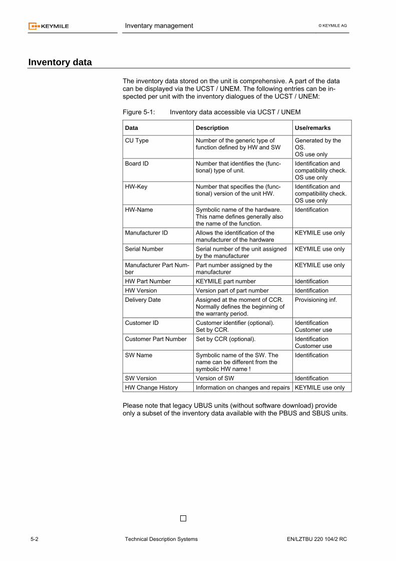
The inventory data stored on the unit is comprehensive. A part of the data can be displayed via the UCST / UNEM. The following entries can be in-spected per unit with the inventory dialogues of the UCST / UNEM:
Figure 5-1: Inventory data accessible via UCST / UNEM
Data Description Use/remarks
CU Type Number of the generic type of function defined by HW and SW
Generated by the OS. OS use only
Board ID Number that identifies the (func-tional) type of unit.
Identification and compatibility check.OS use only
HW-Key Number that specifies the (func-tional) version of the unit HW.
Identification and compatibility check. OS use only
HW-Name Symbolic name of the hardware. This name defines generally also the name of the function.
Identification
Manufacturer ID Allows the identification of the manufacturer of the hardware
KEYMILE use only
Serial Number Serial number of the unit assigned by the manufacturer
KEYMILE use only
Manufacturer Part Num-ber
Part number assigned by the manufacturer
KEYMILE use only
HW Part Number KEYMILE part number Identification HW Version Version part of part number Identification Delivery Date Assigned at the moment of CCR.
Normally defines the beginning of the warranty period.
Provisioning inf.
Customer ID Customer identifier (optional). Set by CCR.
Identification Customer use
Customer Part Number Set by CCR (optional). Identification Customer use
SW Name Symbolic name of the SW. The name can be different from the symbolic HW name !
Identification
SW Version Version of SW Identification HW Change History Information on changes and repairs KEYMILE use only
Please note that legacy UBUS units (without software download) provide only a subset of the inventory data available with the PBUS and SBUS units.
© KEYMILE AG
EN/LZTBU 220 104/2 RC Technical Description Systems 6-1
Maintenance 6
Upgrading
The verification of the compatibility of the new hardware with the system before the upgrade is essential!
Upgraded or new units can be plugged into the powered subrack. Units with SW download require a suitable ESW.
The inventory data and the identification label on the front panel of upgraded hardware have to be adapted accordingly. To comply with this requirement all hardware has to be upgraded as instructed by the manufacturer. Such a procedure ensures correct CCR processing for the upgraded hardware. Cor-rect CCR (Customer Configuration Registration) is a prerequisite for rapid and efficient after sales service. The verification of the compatibility of the hardware providing protection with the system and units before the upgrade is essential!
You can implement the protection of the power supply and the system con-trol at any time without interrupting traffic signals (payload). You must follow the rules provided for the implementation of units. For some signals (man-agement communication, timing sources, alarm signals etc.) you may need to install additional cabling, in order to provide full functional protection. The verification of the compatibility of the new ESW with the unit hardware and the UCST / UNEM version before the upgrade is essential!
Upgrading the ESW requires management access of the UCST / UNEM to the NE with the units to upgrade. The ESW is upgraded as follows:
• The new ESW is first delivered to the NE (to the MIB of the COBU<X>).
• Afterwards the installation of the new ESW has to be configured by means of the corresponding menus of the UCST / UNEM for all the units affected. You can program the installation for immediate application or for sched-uled installation at a defined date and time. This last feature allows the simultaneous installation (and application) of new ESW throughout the whole access network.
• The identification label on the front panel is not affected.
Upgrading hardware
Upgrading with hardware protection
Upgrading unit SW Units with SW download
Maintenance © KEYMILE AG
6-2 Technical Description Systems EN/LZTBU 220 104/2 RC
The verification of the compatibility of the upgraded function with the unit hardware and the UCST /UNEM before the upgrade is essential!
For units without SW download, you can upgrade the unit SW by changing the corresponding FW PROM. A functional upgrade for units without SW download corresponds to an upgrade of the hardware.
The inventory data and the identification label on the front panel of function-ally upgraded units have to be adapted accordingly. To comply with this re-quirement you have to upgrade all hardware as instructed by the manufac-turer. This ensures correct CCR (Customer Configuration Registration) processing for the upgraded hardware. Correct CCR is a prerequisite for rapid and efficient after sales service. When upgrading the UCST / UNEM, the new UCST / UNEM is generally able to handle the legacy NE configuration files.
The release notes and user guides provide corresponding upgrade proce-dures and information on limitations.
For more information, refer also to the paragraphs "Compatibility of system functions" in chapter 5: "Functional descriptions" [200].
Units without SW download
Upgrading the UCST / UNEM
Maintenance © KEYMILE AG
EN/LZTBU 220 104/2 RC Technical Description Systems 6-3
UMUX spare units
The UMUX system and its units feature high MTBF (Mean Time Between Failure) values.
Low MTTR (Mean Time To Repair) values are feasible because of
• Quick location of failures due to the comprehensive operation and main-tenance concept of the UMUX.
• Quick replacement of failed units due to − inventory data identifying equipment and easing the logistics and pro-
visioning of spare units − front access of signal cables − central MIB database allowing immediate automatic re-programming
of the operational parameters for the substitute unit. − SW download (new units only) reconfiguring the unit SW (ESW) for
the configured unit function independently of the former unit history.
• Functional protection of the power supply If the NE features equipment protection for the power converter units, single or multiple unit failures (depending on the degree of protection) will not affect the system operation.
• Functional protection of the control unit If the NE features equipment protection for the control units, the failure of a control unit will not affect system operation (excepted for some bit er-rors in the traffic signals connected via the UBUS and via the PBUS).
It is essential that you dispose of spare units to re-establish or maintain the original degree of the quality of service after a failure:
• For units without functional protection (traffic, transmission units): − a minimum of 1 unit of each type, or − 2 … 4% for each type of unit in service
• For units with functional protection (power supply, control units) − a minimum of 1 unit of each type, or − 1 … 2% for each type of unit in service
Please note that the above figures are valid considering that:
• The failed units are immediately sent to the manufacturer for repair.
• The reduced number of reserve units for power supply and con-trol units as indicated above only apply if the corresponding protection has been implemented for a large majority of the NEs.
Maintenance © KEYMILE AG
6-4 Technical Description Systems EN/LZTBU 220 104/2 RC
Manipulation of the equipment
All units can be plugged into / removed from the powered UMUX subrack.
If a unit is extracted, the traffic and functions affected by the respective unit are interrupted.
Traffic and functions are not affected, if the control and/or power units with protecting units in hot standby mode are removed.
Plugging a unit into the wrong slot position does not cause damage to the unit nor to the surrounding equipment. For the system to operate successfully take care to adhere to the rules for correct unit to slot assignment in the slot ar-rangement of the subrack. This applies in particular for the control units.
The UMUX units contain components which are sensitive to discharges of static electricity. To avoid damages, precautions must be followed as de-scribed in [033] when handling UMUX units. The UMUX subrack is usually mounted in a 19-inch or an ETSI rack suited to miscellaneous types of equipment. The installation of the UMUX subrack into an ETSI rack requires the ETSI rack mounting kit with corresponding adapters.
During operation, install the front cover of the subrack and ground the cables as instructed to provide the specified ESD and EMC characteristics.
All UMUX units are plug-in units with front access for traffic and infrastruc-ture signals. They are usually plugged in and connected during installation. For upgrade and maintenance purposes, units can be plugged in and taken out while powered. Configured units will create alarms as specified by the unit configuration. Some of the UMUX units support the optical transmission of data signals with optical laser systems. Inexpert operation and handling of laser based transmission systems can provoke injuries.
For details of safety aspects and precautions, refer to [033]. Some UMUX equipment operates from mains. Inexpert handling of equip-ment connected to the mains can provoke danger to life.
For details of safety aspects and precautions, refer to [033]. For safety reasons and to economically achieve a high degree of quality of service with UMUX and its components, KEYMILE strongly recommends that network operators train their staff for the installation and operation of UMUX components. Only persons who have been trained and authorised by the network operator can be permitted to work with UMUX.
The responsibility for fulfilling the above obligations lies with the network op-erators and their management staff. KEYMILE does not keep records of exter-nal staff who have been trained and authorised, and therefore accepts no re-sponsibility in case of accidents and/or low quality of service in the network.
For details of the currently available training units, refer to the current KEYMILE technical training program.
Unit handling
Equipment handling
Safety aspects Optical transmission
Interface to mains
Training
© KEYMILE AG
EN/LZTBU 220 104/2 RC Technical Description Systems 7-1
Documentation and training 7
Technical customer documentation
Structure The UMUX Technical Customer Documentation (TCD) provides all the in-formation required for the operation and maintenance of the components of the UMUX Multiservice Access Platform (MAP).
The TCD of the UMUX MAP is modular and contains multiple documents. Each document belongs to a document type. The document types are opti-mised for their purpose of use and the maintenance of the documentation.
The full TCD of the UMUX MAP with release R<x> consists of the individual documents and the release R<x> specific definition of the structure of the TCN. This structure defines the hierarchical relationship and the release of each individual document. The customer documentation of the UMUX Multiservice platform has docu-ment types as follows
• Technical Descriptions Technical descriptions provide technical data and descriptions of fea-tures, functions and architecture of the components of the UMUX MAP. Technical descriptions are available on the EM, the NE and unit level.
• User Guides User guides provide instructions, procedures and information for the in-stallation and operation of the components of the UMUX MAP. User guides are available on the EM, the NE and unit level.
• User Manuals User manuals provide instructions, procedures and information for the in-stallation and operation of CPE components of the UMUX MAP. User manuals are available for CPE and desktop equipment.
• Release information The features and functions of the UMUX Multiservice platform releases are specified via 2 documents − Release Note
Release notes provide short functional specifications of new or modi-fied platform features as well as details of the released hardware and software (ESW) and a summary of fixed bugs (with service packs).
Document types
Documentation and training © KEYMILE AG
7-2 Technical Description Systems EN/LZTBU 220 104/2 RC
− Letter of Limitations Letter of limitations provide a summary of functional limitations en-countered with the related release.
Release note and letter of limitation are released with each major UMUX platform release and updated for each service pack.
• Engineering Bulletins Engineering bulletins provide information on selected technical issues, mainly descriptions of proprietary applications and work around solutions for problems encountered with special application of UMUX equipment. Engineering bulletins are created for all aspects of the UMUX Multiser-vice platform. Engineering bulletins have a level of confidentiality. Bulletins with the level "unrestricted" are generally released with the technical customer documentation.
The customer documentation of the UMUX MAP and its components is pub-lished and available as follows:
• CD-ROM All components (including EBs with confidentiality level "unrestricted") of the customer documentation are available on 2 CD-ROMs (pdf format) with fully linked contents: − UMUX Multiservice platform including UCST − UNEM
For more information of the available CD-ROM based TCD, refer to the release note [053].
• Hardcopies Hardcopies of the components of the UMUX MAP are available as follows: − Set of binders (manuals)
Sets of binders (manuals) contain all the documents of a document type and are structured according to the system architecture. Sets of binders are available for - Technical descriptions (UMUX, units) - User Guides (UMUX, units, UCST) − UNEM documentation
− User Manuals User manuals are distributed with the relevant CPE and desktop equipment.
For more information of the available hardcopy based technical customer documentation, refer to the release note [053].
• Extranet The UMUX and UNEM TCD is published in KEYMILE's extranet. Customers with a corresponding SLA (Service Level Agreement) have access to the most recent customer documentation and additional services as specified in their service level agreement. This includes the access to the unit ESW (Embedded SW) and customer specific engineering bulletins.
For more information on SLA, refer to your KEYMILE sales contact or the KEYMILE customer support.
Publication
Documentation and training © KEYMILE AG
EN/LZTBU 220 104/2 RC Technical Description Systems 7-3
Technical customer training
The UMUX is a highly complex technical system with user friendly manage-ment systems for system configuration and operation control. The UCST and UNEM support the staff with performance control and diagnostic func-tions for the UMUX equipment to implement and maintain a high level of service quality in the UMUX network.
The complexity of the traffic functions supported by UMUX and the proper application of the UMUX functions require that staff must be trained for UMUX operation and maintenance. Although the customer documentation specifies and describes all the details of installation, operation and mainte-nance of the UMUX Multiservice platform only theoretical and practical train-ing in conjunction with the customer documentation can provide the skills required for successful and economic equipment operation.
KEYMILE provides adequate technical training for staff with a modular train-ing program. The training program consists of courses which train
• Fundamentals of UMUX operation & maintenance
• UMUX management communication (MCN) commissioning and opera-tion
• Traffic functions and applications (courses per traffic function) such as − ATM traffic functions − SDH traffic functions − V5.x traffic functions − Access router functions
• UNEM operation and administration
• MCN engineering
The training program is updated for each platform release and new traffic functions.
For details of the currently available courses, refer to the current KEYMILE training program.
Documentation and training © KEYMILE AG
7-4 Technical Description Systems EN/LZTBU 220 104/2 RC
System labelling
Each system and unit with active components carries an identification label on the front. The label is an integral part of the unit and must never be re-moved.
Depending on the functional level of the unit, the layout of the label is slightly dif-ferent. The main types (functional levels) of labels (used with the UMUX) are
• Unit hardware for units with SW download
• Unit function for − units without SW − units with FW
• Subrack and CE brand
Detailed information on labels and their contents is provided in the following paragraphs. The label specifies hardware only. To create a FUNCTION, requires a unit hardware and an ESW (Embedded SW).
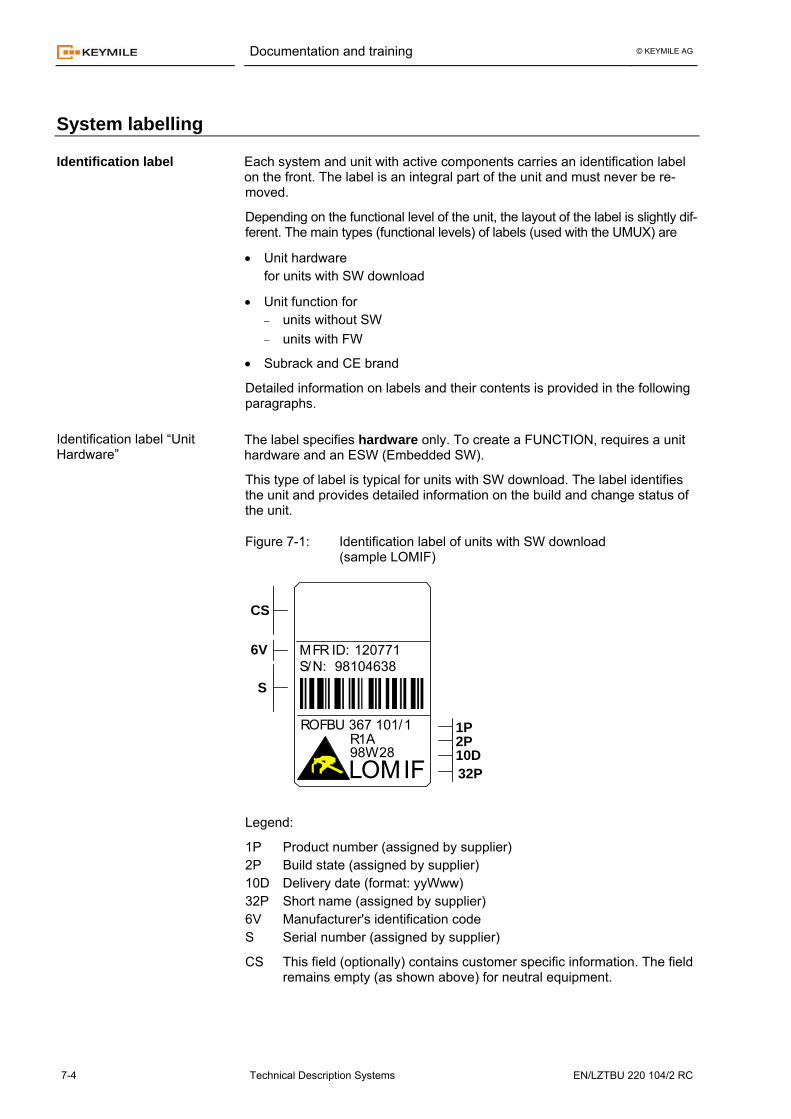
This type of label is typical for units with SW download. The label identifies the unit and provides detailed information on the build and change status of the unit.
Figure 7-1: Identification label of units with SW download (sample LOMIF)
LOMIF
ROFBU 367 101/1
98W2832P10D
1PR1A 2P
S
120771S/N:MFR ID:
981046386V
CS
Legend:
1P Product number (assigned by supplier) 2P Build state (assigned by supplier) 10D Delivery date (format: yyWww) 32P Short name (assigned by supplier) 6V Manufacturer's identification code S Serial number (assigned by supplier)
CS This field (optionally) contains customer specific information. The field remains empty (as shown above) for neutral equipment.
Identification label
Identification label “Unit Hardware”
Documentation and training © KEYMILE AG
EN/LZTBU 220 104/2 RC Technical Description Systems 7-5
Please note that:
• It is essential to replace or updated the identification label if the hardware is modified.
• Due to the hardware designation of such units, you cannot read the name of the UCST template (*.cdu, *.ocu, *.cox etc.) from the label.
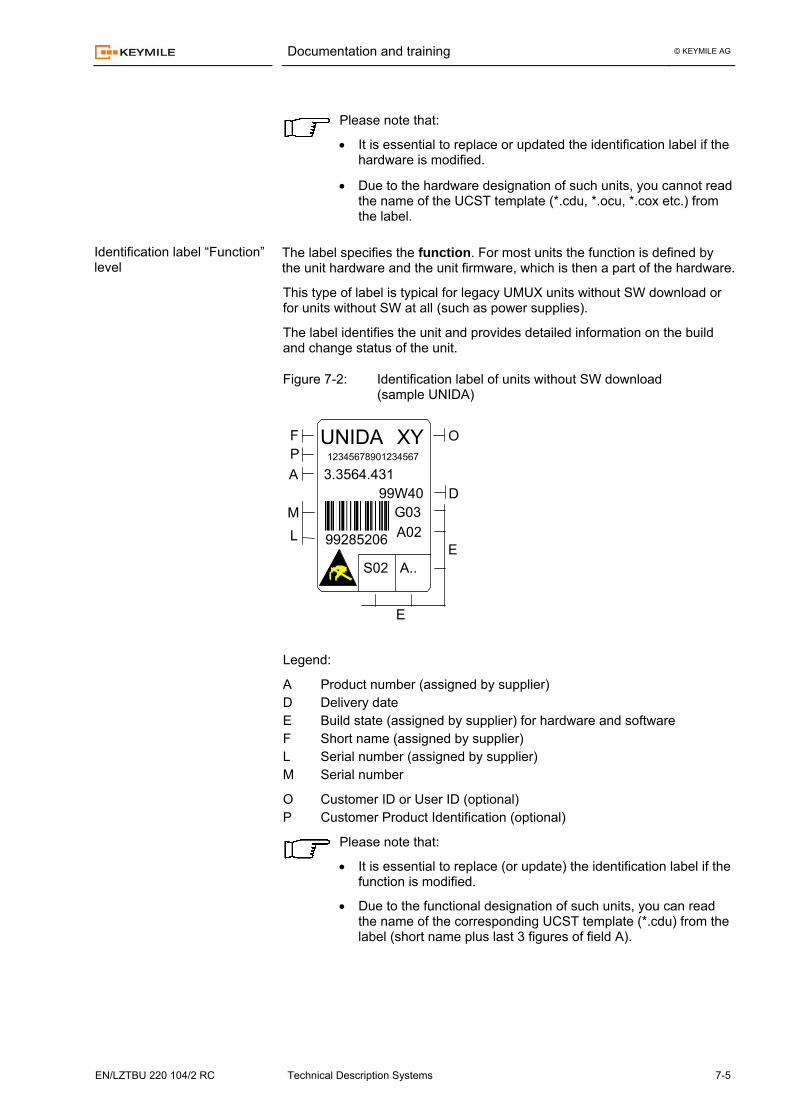
The label specifies the function. For most units the function is defined by the unit hardware and the unit firmware, which is then a part of the hardware.
This type of label is typical for legacy UMUX units without SW download or for units without SW at all (such as power supplies).
The label identifies the unit and provides detailed information on the build and change status of the unit.
Figure 7-2: Identification label of units without SW download (sample UNIDA)
UNIDA
3.3564.431
G03A02
12345678901234567
99285206
99W40
XY
A..S02
A
F
LM
E
D
OP
E
Legend:
A Product number (assigned by supplier) D Delivery date E Build state (assigned by supplier) for hardware and software F Short name (assigned by supplier) L Serial number (assigned by supplier) M Serial number
O Customer ID or User ID (optional) P Customer Product Identification (optional)
Please note that:
• It is essential to replace (or update) the identification label if the function is modified.
• Due to the functional designation of such units, you can read the name of the corresponding UCST template (*.cdu) from the label (short name plus last 3 figures of field A).
Identification label “Function” level
Documentation and training © KEYMILE AG
7-6 Technical Description Systems EN/LZTBU 220 104/2 RC
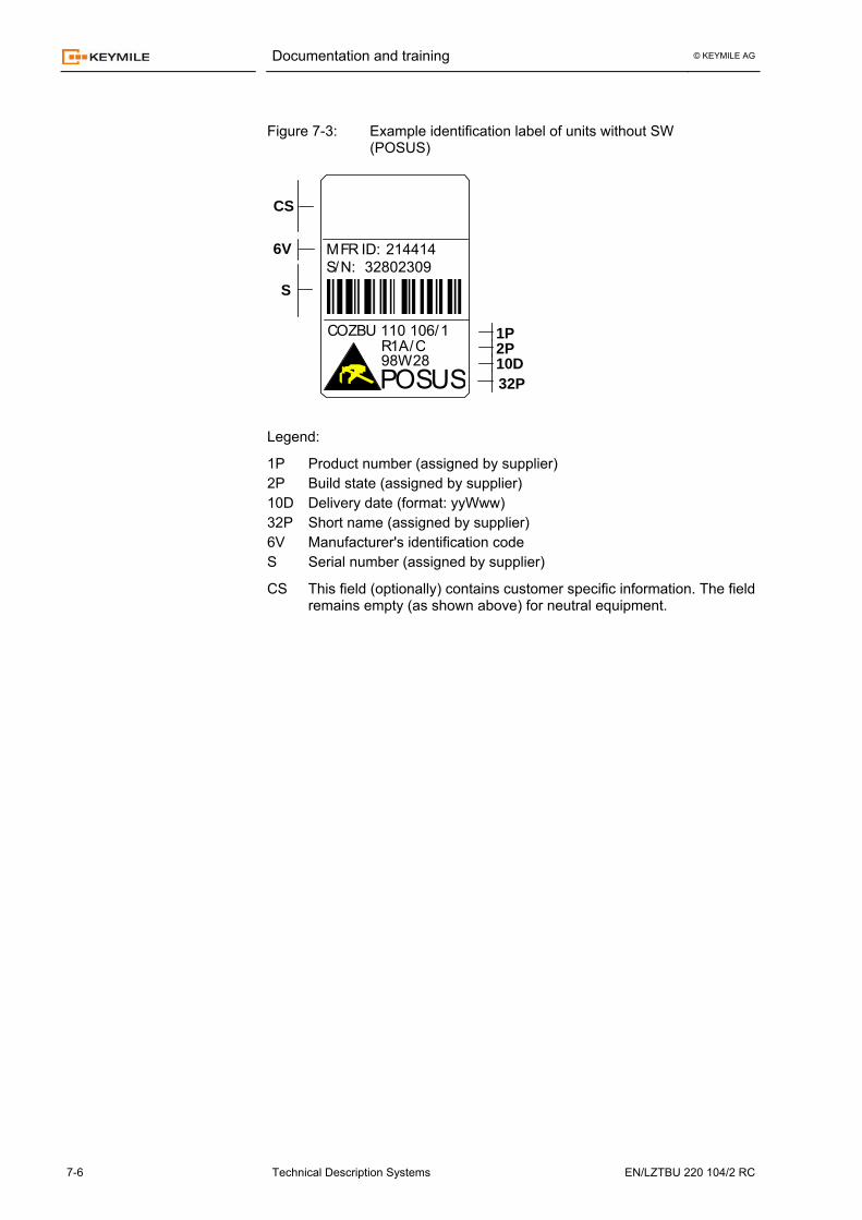
Figure 7-3: Example identification label of units without SW (POSUS)
POSUS
COZBU 110 106/1
98W2832P10D
1PR1A/C 2P
S
214414S/N:MFR ID:
328023096V
CS
Legend:
1P Product number (assigned by supplier) 2P Build state (assigned by supplier) 10D Delivery date (format: yyWww) 32P Short name (assigned by supplier) 6V Manufacturer's identification code S Serial number (assigned by supplier)
CS This field (optionally) contains customer specific information. The field remains empty (as shown above) for neutral equipment.
Documentation and training © KEYMILE AG
EN/LZTBU 220 104/2 RC Technical Description Systems 7-7
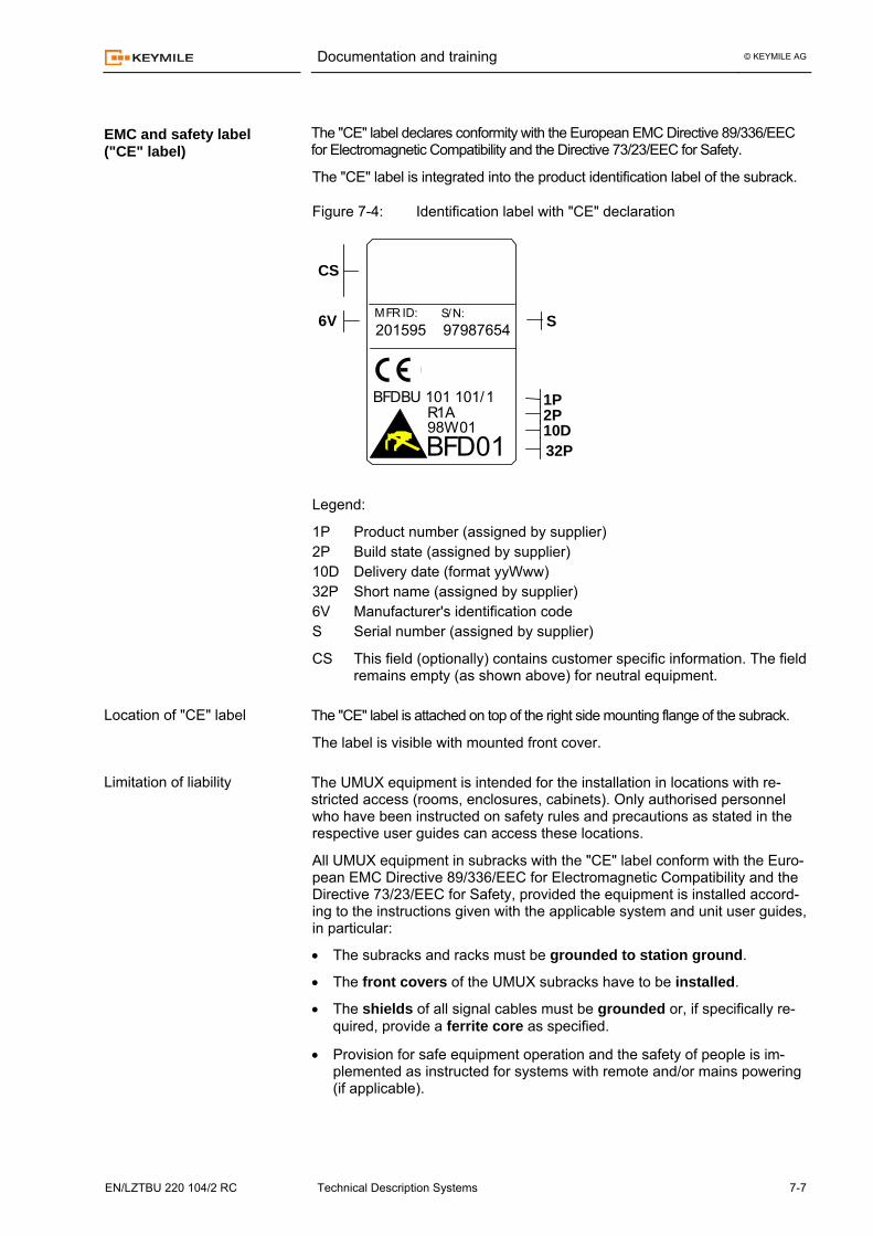
The "CE" label declares conformity with the European EMC Directive 89/336/EEC for Electromagnetic Compatibility and the Directive 73/23/EEC for Safety.
The "CE" label is integrated into the product identification label of the subrack.
Figure 7-4: Identification label with "CE" declaration
BFD01
BFDBU 101 101/1
98W0132P10D
1PR1A 2P
201595 97987654S/N:MFR ID:6V S
CS
Legend:
1P Product number (assigned by supplier) 2P Build state (assigned by supplier) 10D Delivery date (format yyWww) 32P Short name (assigned by supplier) 6V Manufacturer's identification code S Serial number (assigned by supplier)
CS This field (optionally) contains customer specific information. The field remains empty (as shown above) for neutral equipment.
The "CE" label is attached on top of the right side mounting flange of the subrack.
The label is visible with mounted front cover. The UMUX equipment is intended for the installation in locations with re-stricted access (rooms, enclosures, cabinets). Only authorised personnel who have been instructed on safety rules and precautions as stated in the respective user guides can access these locations.
All UMUX equipment in subracks with the "CE" label conform with the Euro-pean EMC Directive 89/336/EEC for Electromagnetic Compatibility and the Directive 73/23/EEC for Safety, provided the equipment is installed accord-ing to the instructions given with the applicable system and unit user guides, in particular:
• The subracks and racks must be grounded to station ground.
• The front covers of the UMUX subracks have to be installed.
• The shields of all signal cables must be grounded or, if specifically re-quired, provide a ferrite core as specified.
• Provision for safe equipment operation and the safety of people is im-plemented as instructed for systems with remote and/or mains powering (if applicable).
EMC and safety label ("CE" label)
Location of "CE" label
Limitation of liability
Documentation and training © KEYMILE AG
7-8 Technical Description Systems EN/LZTBU 220 104/2 RC
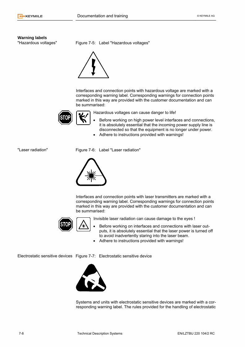
Figure 7-5: Label "Hazardous voltages"
Interfaces and connection points with hazardous voltage are marked with a corresponding warning label. Corresponding warnings for connection points marked in this way are provided with the customer documentation and can be summarised:
Hazardous voltages can cause danger to life!
• Before working on high power level interfaces and connections, it is absolutely essential that the incoming power supply line is disconnected so that the equipment is no longer under power.
• Adhere to instructions provided with warnings!
Figure 7-6: Label "Laser radiation"
Interfaces and connection points with laser transmitters are marked with a corresponding warning label. Corresponding warnings for connection points marked in this way are provided with the customer documentation and can be summarised:
Invisible laser radiation can cause damage to the eyes !
• Before working on interfaces and connections with laser out-puts, it is absolutely essential that the laser power is turned off to avoid inadvertently staring into the laser beam.
• Adhere to instructions provided with warnings!
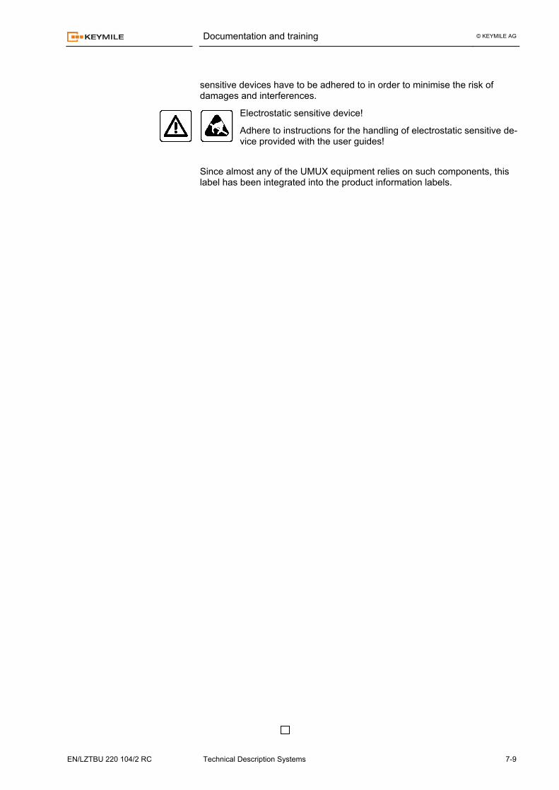
Figure 7-7: Electrostatic sensitive device
Systems and units with electrostatic sensitive devices are marked with a cor-responding warning label. The rules provided for the handling of electrostatic
Warning labels "Hazardous voltages"
"Laser radiation"
Electrostatic sensitive devices
Documentation and training © KEYMILE AG
EN/LZTBU 220 104/2 RC Technical Description Systems 7-9
sensitive devices have to be adhered to in order to minimise the risk of damages and interferences.
Electrostatic sensitive device!
Adhere to instructions for the handling of electrostatic sensitive de-vice provided with the user guides!
Since almost any of the UMUX equipment relies on such components, this label has been integrated into the product information labels.


