Download - TCP Over Wireless
TCP over Wireless Networks
(VTC2000-Fall Tutorial)
Farooq Khan and Sanjiv NandaBell Labs - Lucent Technologies
Holmdel, NJ 07733, USA
September 25, 2000

Why TCP?
• Explosive growth of internet.
• Web browsing (HTTP) contribute to more than 70% of the traffic in the internet.
• HTTP and some other internet applications use TCP as the transport mechanism.
• TCP is tuned to fixed networks (low delay, low error rate).
• Scalability of the internet is enabled by TCP flow control mechanisms.

Why TCP over Wireless?
• Wireless networks that enable high-speed data transfer (3G) are now being introduced.
• Web browsing (using TCP) is expected to be the dominant application in wireless data networks.
• Wireless networks exhibit high delays and high error rates.
• This causes some internet protocols, especially TCP, to perform poorly.

How data is different from voice?
When and how much
Air Interface (RLP, MAC, PHY)
HTTP/TCP
Loss, Delay Variation

Simplified Protocol Stack
Internet protocols
Radio network protocols
HTTP/TCP
RLP/MAC/PHY
HTTP/TCP HTTP/TCP
RLP/MAC/PHY RLP/MAC/PHY
Host
MSBSC/RNC
internet

HTTP Request to Radio Frames
www.yahoo.com
www.yahoo.comHTTP
www.yahoo.comHTTPTCP
www.yahoo.comHTTPTCPIP
RLP RLPSegmentation
Radio frames
Coding and interleaving etc.
HTTP GET requesthttp://www.yahoo.com
SenderReceiver

Tutorial Outline
Introduction
RLP TCP HTTP
TCP over Wireless Performance Issues
TCP Performance
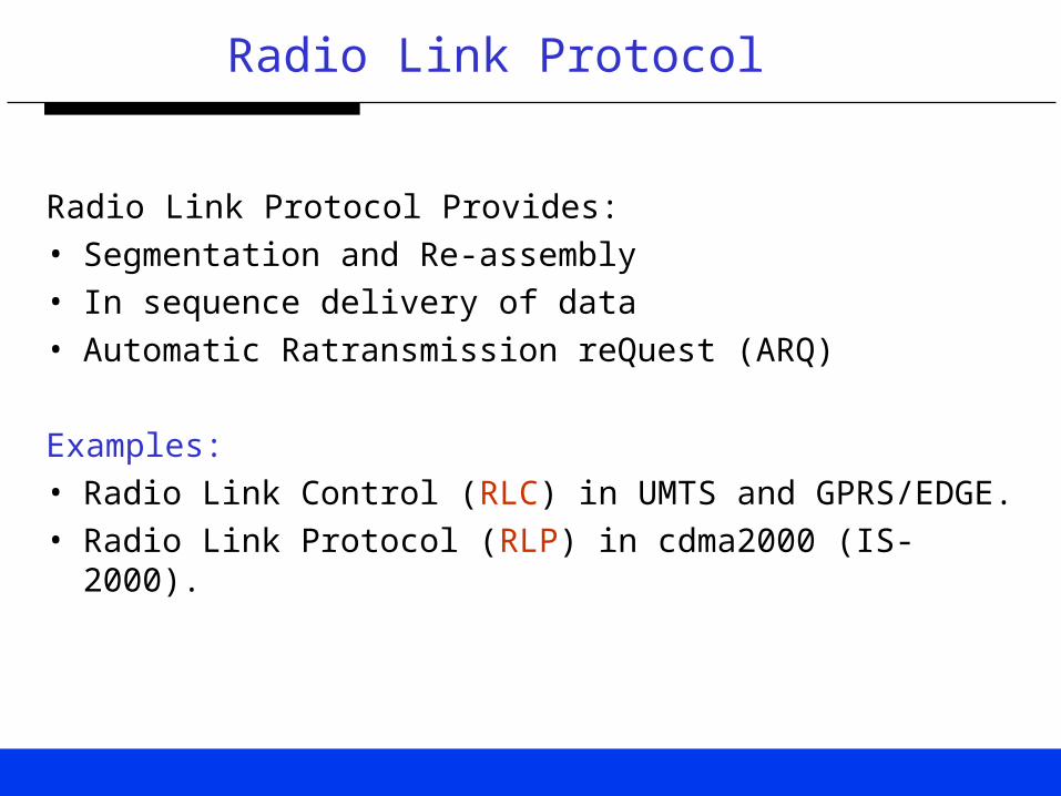
Radio Link Protocol
Radio Link Protocol Provides:• Segmentation and Re-assembly• In sequence delivery of data• Automatic Ratransmission reQuest (ARQ)
Examples:• Radio Link Control (RLC) in UMTS and GPRS/EDGE.• Radio Link Protocol (RLP) in cdma2000 (IS-2000).

IS-2000 RLP
• NAK-Based
• RLP Type 3 supports 2 rounds of NAKs.
• Two NAKs in the first round and three NAKs in the second round.
• In RLP Type 3 enhanced, the number of rounds and NAKs/retransmissions sent in each round are configurable.
• The configuration parameters are determined during RLP set up process through negotiation between the mobile terminal and the network.

RLP Type 3
TX
RX
RTX Timer Abort Timer
1 2 3
2 2
2 2 2
At the expiry of abort timer, the RLP receiver will deliverframes 1 and 3 to higher layer.
NAKs NAKs
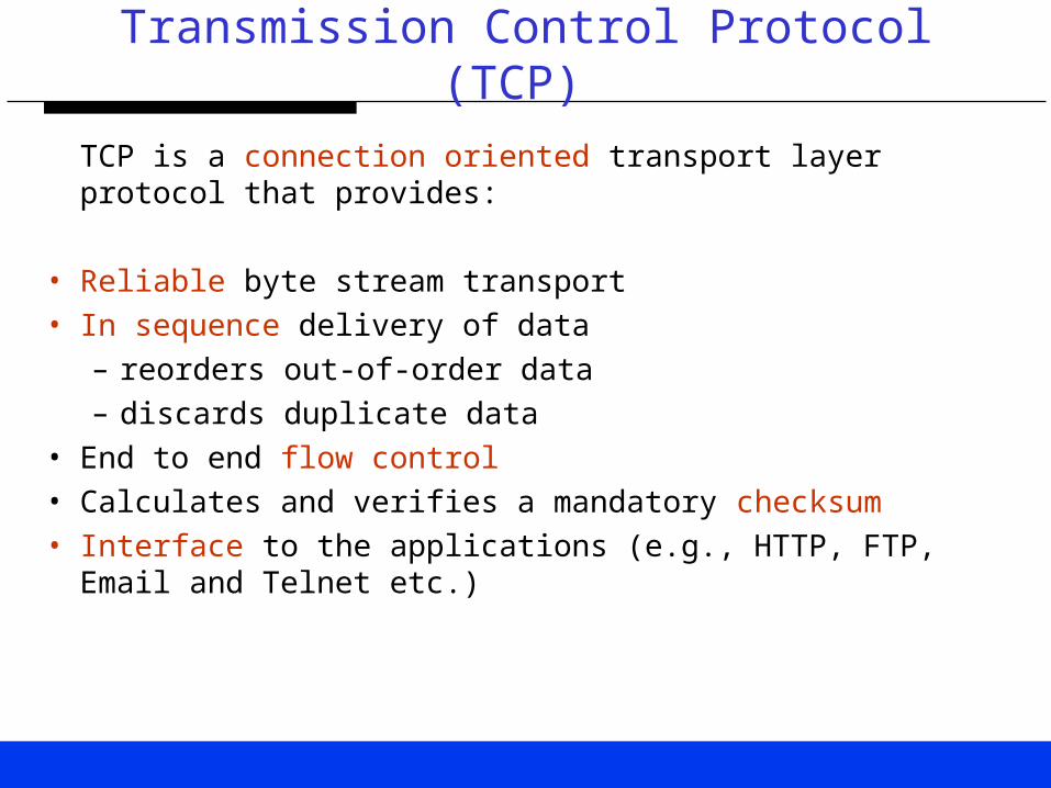
Transmission Control Protocol (TCP)
TCP is a connection oriented transport layer protocol that provides:
• Reliable byte stream transport• In sequence delivery of data
– reorders out-of-order data– discards duplicate data
• End to end flow control• Calculates and verifies a mandatory checksum• Interface to the applications (e.g., HTTP, FTP, Email and Telnet
etc.)

TCP Header
16-bit source port number 16-bit destination port
32-bit sequence number
32-bit acknowledgment number
4-bit HLEN
Reserved 16-bit window size
16-bit urgent pointer16-bit TCP checksum
ACKPSHRSTSYN FINURG
20 bytes

TCP Connection Management
TX
RX
SYN(K)
SYN(J)ACK(K+1)
ACK(J+1) FIN(M)
ACK(M+1) FIN(N)
ACK(N+1)
Data flow
JK+1
ACK PSH RST SYN FINURG
20 bytes
[SYN(J), ACK(K+1)]

Loss Detection
• TCP Data and ACKs can get lost due to congestion or transmission errors.
• Two different ways to detect loss:– Retransmission timeout– Duplicate ACKs

TCP Timeout
• TCP sets a timeout, when it sends data.
• If the data is NOT acknowledged when the timeout expires
• TCP retransmits the data.

Exponential Back-off
RTO=T RTO=2T RTO=4T
TX
RX
RTO = mean RTT+ 4(mean deviation of RTT)

Duplicate ACKs
• After receiving three duplicate ACK,
• TCP sender assumes that the segment is lost and,
• Perform a retransmission
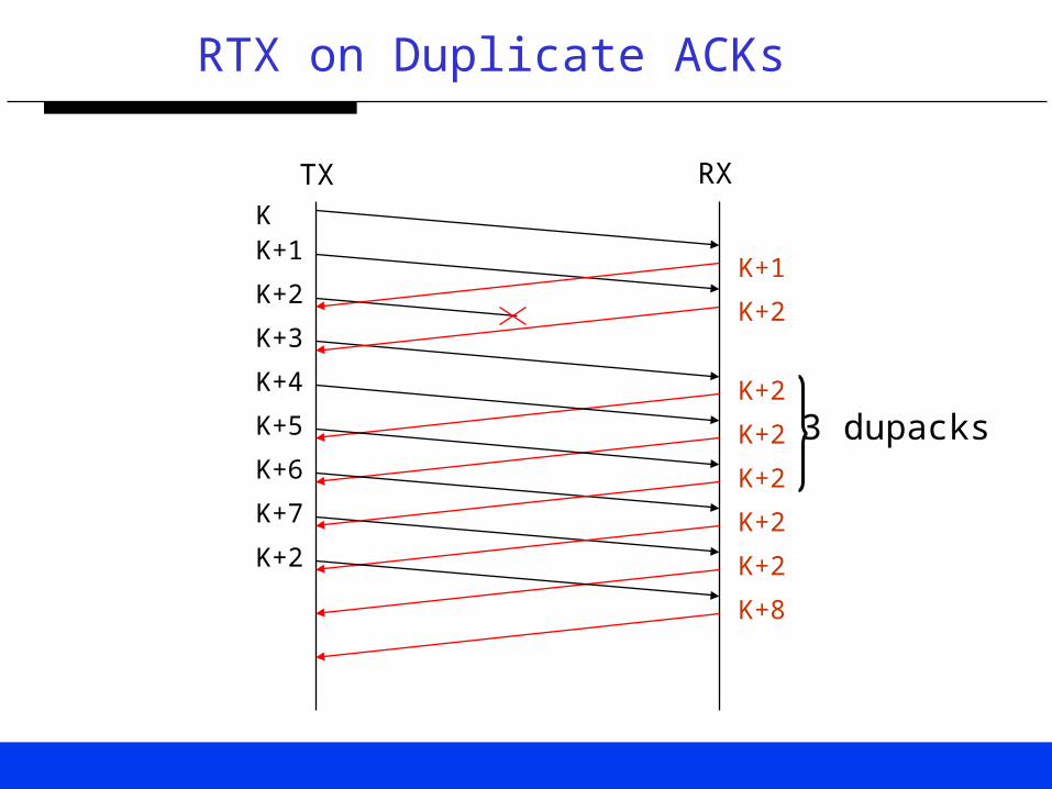
RTX on Duplicate ACKs
KK+1
K+2
K+3
K+1
K+2
K+2
K+2
K+2
K+2
K+2
K+7
K+4
K+5
K+6
3 dupacks
K+2
K+8
TX RX

TCP flow Control
• The congestion window (cwnd) is flow control imposed by the sender.
• While the advertised window is flow control imposed by the receiver.
• The former is based on the sender's assessment of perceived network congestion; the latter is related to the amount of available buffer space at the receiver for this connection.
• Current window = min(cwnd, advertised win).

Window Based Flow Control
1 2 3 4 5 6 7 8 9 10
ACKs received
Window size
Can't send untilwindow moves
Sent, not ACKed
Can send ASAP

TCP Slow Start
• Initially, cwnd=MSS;
• Each time an ACK is received, cwnd cwnd+MSS;
• This provides an exponential growth, although it is not exactly exponential because the receiver may delay its ACKs, typically sending one ACK for every two segments that it receives.
Maximum Segment Size (MSS) is the largest “chunk” of data that TCP will send to the other end. When a connection is established, each end can announce its MSS.

Congestion Avoidance
• Congestion avoidance and slow start require that two variables be maintained for each connection: a congestion window, cwnd, and a slow start threshold size, ssthresh.
• Initially, cwnd MSS, ssthresh=65KB.
• Current win min (cwnd, advertised window)
Congestion Avoidance
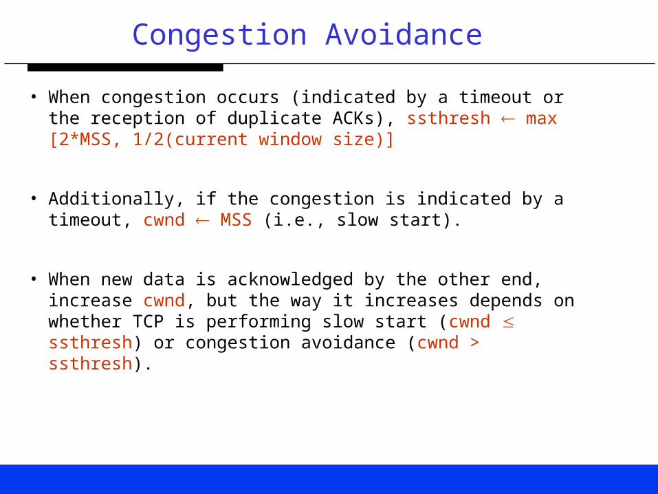
• When congestion occurs (indicated by a timeout or the reception of duplicate ACKs), ssthresh max [2*MSS, 1/2(current window size)]
• Additionally, if the congestion is indicated by a timeout, cwnd MSS (i.e., slow start).
• When new data is acknowledged by the other end, increase cwnd, but the way it increases depends on whether TCP is performing slow start (cwnd ssthresh) or congestion avoidance (cwnd > ssthresh).

Congestion Avoidance Example
CurrentWindow
Advertisedwindow
cwnd ssthresh
t 1.5KB 65KB 1.50KB 65KB
t+ 65KB 65KB 75.0KB 65KB
RTX due todupacks
65KB 65KB 75.0KB 32.5KB
RTX due totimeout
1.50KB 65KB 1.50KB 32.5KB

Congestion Avoidance
• In congestion avoidance, each time an ACK is received, cwnd MSS*MSS/cwnd. For example, MSS=1500 bytes, current cwnd=6000 bytes, the new cwnd = 6375 bytes
• This is a linear growth of cwnd, compared to slow start's exponential growth.
• The increase in cwnd should be at most one MSS each RTT (regardless how many ACKs are received in that RTT), whereas slow start increments cwnd by the number of ACKs received in an RTT.
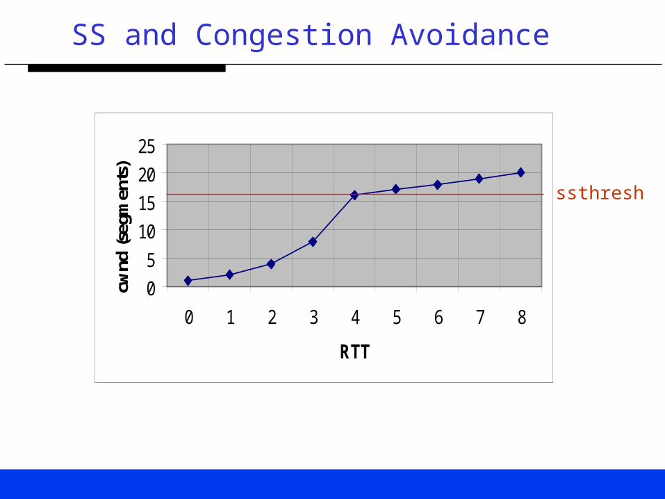
SS and Congestion Avoidance
0
5
10
15
20
25
0 1 2 3 4 5 6 7 8
RTT
cwnd
(seg
men
ts)
ssthresh

HyperText Transfer Protocol (HTTP)
• HTTP is a simple protocol that forms the basis for the Web.
• The HTTP client (web browser) establishes a TCP connection to the HTTP server
• Issues a request, and reads back the server’s response
• The server closes the TCP connection at the end of its response.

Web Browsing (HTTP/1.0)
TCP TCP
Web browser Web server
Internet
The biggest performance problem associated with HTTP is itsuse of one TCP connection per web object (file).

HTTP/1.0 (Continued)
• HTTP/1.0 opens and closes a new TCP connection for each web object transfer.
• Most Web objects are small (1-5KB).
• High fraction of packets are simply TCP control packets used to open and close a connection.

HTTP/1.0 (Continued)
• Due to TCP slow start, most objects are transferred before their TCP connection completes the slow start algorithm.
• Most HTTP/1.0 operations use TCP at its least efficient.
• Major problems due to resulting congestion and unnecessary overhead.

HTTP/1.0 (Continued)
A
B
C
D
E
Web page transfer time
Web object (A) transfer time
4 parallel TCP connections
Completion of index.html
Completion of E and start of F
F
Packet Bursts

HTTP/1.0 (Continued)
• First TCP connection (A) is for the home page (GET /).
• This HTML document refers to 5 GIF images (B through F).
• As soon as this home page is received by the client, four TCP connections are opened in parallel for the first four images (B through E).
• As soon as one of these connections terminates, another connection is immediately established to fetch the next and last image F.

HTTP/1.1
• HTTP/1.1 leaves the TCP connection open between consecutive operations.
• This technique is called "persistent connections," which both avoids the costs of multiple opens and closes and reduces the impact of slow start.
• Persistent connections are more efficient than the current practice of running multiple short TCP connections in parallel.

HTTP/1.1 (Continued)
• By leaving the TCP connection open between requests, many packets can be avoided
• While avoiding multiple RTTs due to TCP slow start.

Related IETF Working Groups
• IETF HTTP (HyperText Transfer Protocol) Working Group – http://www.ietf.org/html.charters/http-charter.html
• IETF Transport Area (TCP) Working Group – http://www.ietf.org/html.charters/tsvwg-charter.html
• IETF PILC (Performance Implications of Link Characteristics) Working Group – http://www.ietf.org/html.charters/pilc-charter.html

Air Interface (AI) Characteristics
Wireless networks are characterized by:
• High Latency (over-the-air and in the access network)
• Variable Delays (e.g., due to link layer retransmissions)
• High Error Rate (e.g., due to fading etc.)
• Variable Data Rate (due to varying channel conditions)
• Handoffs (due to mobility)

High Latency (1)
Wireless System Delay (RTT)
(ms)
Bandwidth
(Kb/s)
Delay*Bandwidth Product
(Bytes)
W-LAN 3 1500 563
GSM, IS-95 500 9.6 600
Richochet 500 128.0 8KB
3G Wireless 200 384 9600 > 8KB
The delay bandwidth product for 3G wireless is largerthan the default 8KB buffer space used by many TCPimplementations.

High Latency (2)
576B
Delay=100ms, Rate=384Kb/s
12ms
TCPsender
Maxbufferspace=8KB
TCPreceiver
40ms
Maximum number of outstanding segments = Floor(8KB/576B)=13
Delay=100ms, Rate=384Kb/s
ACKs
Data
12ms
Wasted BW

High Latency (3)
• A buffer space (window size) smaller than the delay bandwidth product result in wasted bandwidth due to inefficient pipe filling.
• The maximum achievable throughput is limited to (window size)/RTT.

Variable Delays
TCP RTO = mean RTT+4 (mean deviation of RTT)
HTTP/TCP HTTP/TCP
RLP/MAC/PHY RLP/MAC/PHY
Host
MSBSC/RNC
internet
Large variations in the RTT (due to RLP retransmissions) increase the RTO
RLP Retransmissions
Errors

High Error Rate
Host RNC MSErrors
Loss due to buffer over-flowin the internet routers
Loss due to RLP residual errors(after max number of RTX attempts)
• TCP congestion control is tuned to networks that lose traffic primarily because of congestion and buffer exhaustion.
• Interact badly with connections that lose data due to transmission errors.
Router

Variable Data Rate
• Variable data rates introduce transmission time variations, leading to RTT variations.
• Large variations in the RTT increase the RTO.
• Increased RTO increases the overall data transfer times (e.g., web page transfer times) due to slow response to recover from lost data.
• Data rate variations (high data rate to low data rate) in the start of a connection can lead to duplicate transmissions from TCP.

Handoffs
• Variations in RTT due to delay associated with Handoffs.
• TCP timeouts (and duplicate transmissions) due to sudden increase in delays seen by TCP (RTO cannot be adjusted so fast).

Potential Enhancements to TCP
Fast Rtx. and Fast Recovery
Slow Start Proposals
Delayed Duplicate Acks
Split TCP and PEPs
Selective Acks
For a complete list of enhancements, see:draft-montenegro-pilc-ltn-01.txt.
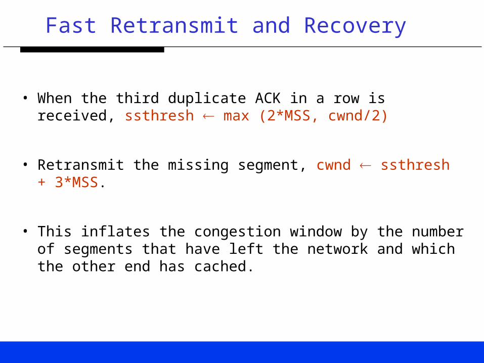
Fast Retransmit and Recovery
• When the third duplicate ACK in a row is received, ssthresh max (2*MSS, cwnd/2)
• Retransmit the missing segment, cwnd ssthresh + 3*MSS.
• This inflates the congestion window by the number of segments that have left the network and which the other end has cached.

Fast Retransmit and Recovery
• Each time another duplicate ACK arrives, cwnd cwnd +MSS.
• This inflates the congestion window for the additional segment that has left the network.
• Transmit a packet, if allowed by the new value of cwnd.

Fast Retransmit and Recovery
• When the next ACK arrives that acknowledges new data, cwnd ssthresh.
• This ACK should be the acknowledgment of the missing retransmission, one round-trip time after the retransmission.
• Additionally, this ACK should acknowledge all the intermediate segments sent between the lost packet and the receipt of the first duplicate ACK.
• This step is congestion avoidance, since TCP is down to one-half the rate it was at when the packet was lost.

Fast Retransmit and Recovery
• The fast retransmit algorithm first appeared in the 4.3BSD Tahoe release, and it was followed by slow start. The fast recovery algorithm appeared in the 4.3BSD Reno release.

Fast RTX and Fast Recovery
KK+1
K+2
K+3
K+1
K+2
K+2
K+2
K+2
K+2
K+2
K+7
K+4
K+5
K+6
3 dupacks
K+2Fast RTX
K+8K+8
K+9
K+10
Fast Recovery K+9
TX RX

Slow Start Proposals
• Slow start dominates the network response seen by interactive users at the beginning of a TCP connection.
• Wireless links present long delays
• Stability of the internet is important.
• The slow start proposals should not adversely affect internet congestion levels.
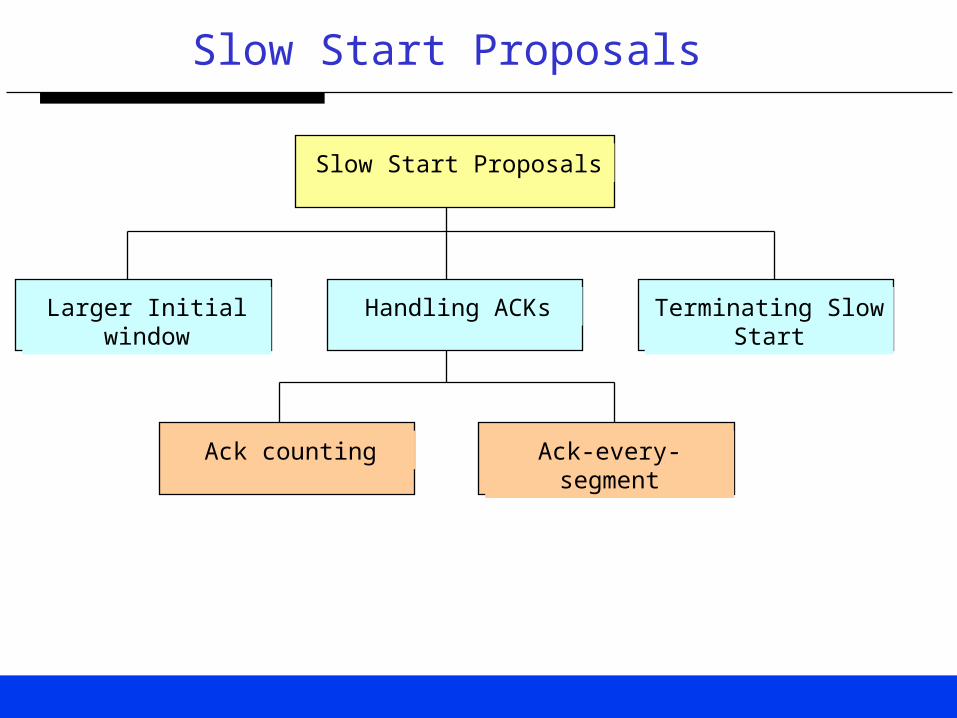
Slow Start Proposals
Slow Start Proposals
Larger Initial window Handling ACKs Terminating Slow Start
Ack counting Ack-every-segment

Larger Initial Window
• Initial win = min (4*MSS, max (2*MSS, 4380 bytes))
Equivalently,
• If (MSS <= 1095 bytes) then win <= 4 * MSS
• If (1095 bytes < MSS < 2190 bytes) then win <=4380 bytes
• If (2190 bytes <= MSS) then win <= 2 * MSS

Larger Initial Window
0
5
10
15
20
25
0 1 2 3 4 5 6 7 8
RTT
cwn
d (
seg
me
nts
)
IW=1
IW=4
ssthresh
Beneficial for short-lived TCP connections or links with long RTT

ACK Counting
• Make each ACK count to its fullest by growing the window based on the data being acknowledged (byte counting).
• May cause bursts that lead to congestion.
• Limit the window growth to 2 segments.

ACK-every-segment
• Keep a constant stream of ACKs coming back by turning off delayed ACKs during slow start.
• Should be limited to slow start only in order to avoid penalizing asymmetric-bandwidth configurations
200-500ms
K
K+1
K+1
K+2

0
5
10
15
20
25
0 1 2 3 4 5 6 7 8
RTT
cwnd
(seg
men
ts)
ssthresh
Terminating Slow Start
• cwnd=ssthresh (instead of cwnd=MSS).• Theoretically, an optimum value for slow-start threshold
(ssthresh) allows connection bandwidth utilization to ramp up as aggressively as possible without “overshoot”.
• No reliable way to measure ssthresh!

Delayed Duplicate ACKs
• The delayed duplicate acknowledgement scheme selectively delays duplicate acknowledgments at the receiver.
• Not so beneficial when link layer guarantees in sequence delivery (link layer residual errors are very small).

Delayed Duplicate ACKs
KK+1
K+2
K+3
K+1
K+2
K+2K+2
K+7
K+8K+8
K+4
K+5
K+6 Delay
Fast RTX
K+9
K+10
Fast Recovery K+9

Selective Acknowledgments (SACK)
• Limited information available from cumulative acknowledgments.TCP sender can only learn about a single lost packet per round trip time
• With SACK, the receiving TCP sends back SACK packets to the sender informing the sender of data that has been received. The sender can then retransmit only the missing data segments
• Useful in cases with considerable probability of multiple segment losses per window.

Selective Acknowledgments
KK+1
K+2
K+3
K
K+1
(K+3, K+4, K+6)K+8
K+7
K+2
K+4
K+5
K+6
K+5
K+9

Split TCP
Host BSC/RNC BS MS
TCP1 TCP2
• Replace an end-to-end TCP connection with two distinct connections: one across the wireless link, the other across the wireline network
Split TCP: Advantages
• Each of the connections can be optimized independently.
• For example, packet losses due to congestion and transmission error can be distinguished.
• Allows earlier deployment of enhancements to TCP over wireless.
• Allows exploitation of various application level enhancements.

Split TCP: Drawbacks
• Breaks TCP end-to-end semantics e.g., disables end-to-end usage of IP layer security mechanisms.
• Crashes of the intermediate node (containing TCP state machine in the radio access network) become unrecoverable.
• Extra overhead in moving TCP states in case of handoff between the intermediate nodes.
• Extra processing overhead at the intermediate node.

Snoop Protocol
• Locally (on the wireless link) retransmit lost packets.• Suppress the duplicate ACKs on their way from the
receiver back to the sender.• Not beneficial when radio link protocol provides in
sequence delivery of frames.• Problem with IPSEC.
Wireless Link
Host BSC/RNC BS MS
Internet

Application Level Proxies
• Employing an application level proxy practically results in a “split TCP” connection.
• The proxy function as the intermediary.
• Avoids overhead on the wireless link e.g., round trips, headers and inefficient coding associated with application protocols.
• Examples: Web proxy caches, relay MTAs (Mail Transfer Agents) and SOCKS etc.

Performance Enhancing Proxy
• Wireless links suffer from periods of disconnection due to handoffs and unavailability of resources etc.
• TCP retransmits data on retransmission timeout (RTO).
• This causes TCP to close its congestion window.
Performance Enhancing Proxy
• Introduce a supervisor host (SH-TCP) at the edge of the wireless link (e.g., at GGSN in GPRS).
• Retain the last ACK coming from the receiver.
• During periods of disconnection, the SH-TCP can shut down the sender’s window by sending the last ACK with a window set to zero.
• This make the sender go to persist mode.

HTTP/TCP/RLP Results
• ns (network simulator) tool.• Web browsing traffic model [Bruce Mah].• HTTP/1.0.• TCP Reno.• IP/PPP overhead taken into account.• IS-2000 forward and reverse link data rates.• One-way Internet delay is fixed at 80ms.• Correlated and i.i.d radio link errors.

HTTP Traffic Model
Web objectsMouse click Mouse click
Web Browsing Session
Web Page Web PageWeb Page
Think Time

HTTP Traffic Model Parameters
HTTP Request Size One large peak around250 bytes and a smallpeak around 1KB
Number ofconnections per webpage
Mean = 3,Median=1
Web object size Mean = 6.75KB
Think Time betweenpages
30* seconds[Exponential distribution]

TCP Parameters
TCP version Reno
TCP maximumsegment size (MSS)
576 or 1500 bytes
TCP receiver windowsize
32KB

Radio Link Parameters
RLP NAK scheme Configurable
One-way radio linkdelay
100ms
RLP guard time 60ms
Radio link data rates 9.6, 19.2, 38.4, 76.8 and153.6 Kb/s.

HTTP Performance Measures
Web Object Transfer Time [secs]
Normalized Web Object Delay [secs/KB]
Web Page Transfer Time [secs]
Normalized Web Page Delay [secs/KB]

Web Object Transfer Time
Object Size: 1-10KB, Data Rate = 38.4 Kb/s
C: Maximum number of parallel TCP connections in HTTP/1.0
0
1
2
3
4
5
0.01
(I.I.d
)
0.05
(I.I.d
)
0.10
(I.I.d
)
0.01
(cor
r)
0.05
(cor
r)
0.10
(cor
r)
FER
Del
ay [
secs
]
C=1
C=4

Normalized Object Delay
0
0.5
1
1.5
2
2.5
3
3.5
4
< 1K B 1K -10K 10K -
20K
20K -
30K
30K -
40K
Objec t S ize
De
lay
[s
ec
s/
Kb
yte
]
0.01(I.I.d)
0.05(I.I.d)
0.10(I.I.d)
Radio link data rate = 38.4 Kb/s, C=1

Object Throughput
0
10
20
30
40
50
60
FE R
Ob
jec
t T
hro
ug
hp
ut
[Kb
/s]
38.4 K b/s
153.6 K b/s
Object Size: 20-30KB, C=1

Web Page Throughput
0
20
40
60
80
100
120
140
FE R
Pa
ge
Th
rou
gh
pu
t [K
b/s
]
C= 1
C= 4
Radio link data rate = 153.6 Kb/s

Normalized Web Page Delay
0
1
2
3
4
5
6
7
8
< 1K B 1K -10K 10-100 100-500 500-1M
Objec t S ize
De
lay
[s
ec
s/
Kb
yte
s]
0.01(corr)
0.05(corr)
0.10(corr)
Radio link data rate =153.6 Kb/s
HTTP Performance Summary
Allowing multiple simultaneous TCP connections for a web page transfer reduce the page transfer times while increasing the individual object transfer times.
Increasing the air link bandwidth will reduce the transfer times for large objects/pages (>1KB) only.
For smaller objects the transfer delay is lower bounded by HTTP request/response delay involving multiple RTTs.

System Capacity with HTTP Traffic
0
20
40
60
80
100
120
140
160
180
0 10 20 30 40 50
Number of HTTP users
Sec
tor
Th
rou
gh
pu
t [K
b/s
]
0.5
0.55
0.6
0.65
0.7
0.75
0.8
0.85
0.9
0.95
1
0 10 20 30 40 50
Number of HTTP users
No
rmal
ized
Del
ay [s
ecs/
KB
]
0.82 s/KB
26 users
120 Kb/s

RLP NAK Schemes
• The Schemes vary in the total number of retransmission rounds and the number of rounds in each round.
• Notation (n1, n2,…, nk) denotes k rounds of retransmissions with n1, n2 and nk NAKs in round 1,2 and k respectively.
• The total number of retransmission attempts is limited to n1+n2 +,.., +nk

Effect of FER on HTTP Performance
OS=10-20KB, i.i.d. errors
0
0.2
0.4
0.6
0.8
1
1.2
1.4
No
rma
lize
d D
ela
y [s
ecs
/KB
]
(1,1,1,1,1)
(2,3)
(1,1,2)
(1,1,3)
(1,2,2)
(1,2,3)

Effect of FER on HTTP Performance
OS=10-20KB, Correlated errors
0
0.2
0.4
0.6
0.8
1
1.2
1.4
No
rma
lize
d D
ela
y [s
ecs
/KB
]
(1,1,1,1,1)
(2,3)
(1,1,2)
(1,1,3)
(1,2,2)
(1,2,3)

RLP Buffers
V(S) -V(N)peer
RTX buffer
New Transmissionbuffer
V(R) -V(N)
RESEQ Buffer
BSC/RNCMS
TCP Segments
TCP Segments
RLP new TX Buffer Size C.D.F.
00.10.20.30.40.50.60.70.80.9
1
0
0.86
1.73
2.59
3.46
4.32
5.18
6.05
6.91
7.78
Buffer Size [KB]
C.D
.F.
FER=0%
FER=10%

Over-the-air Packet Multiplexing
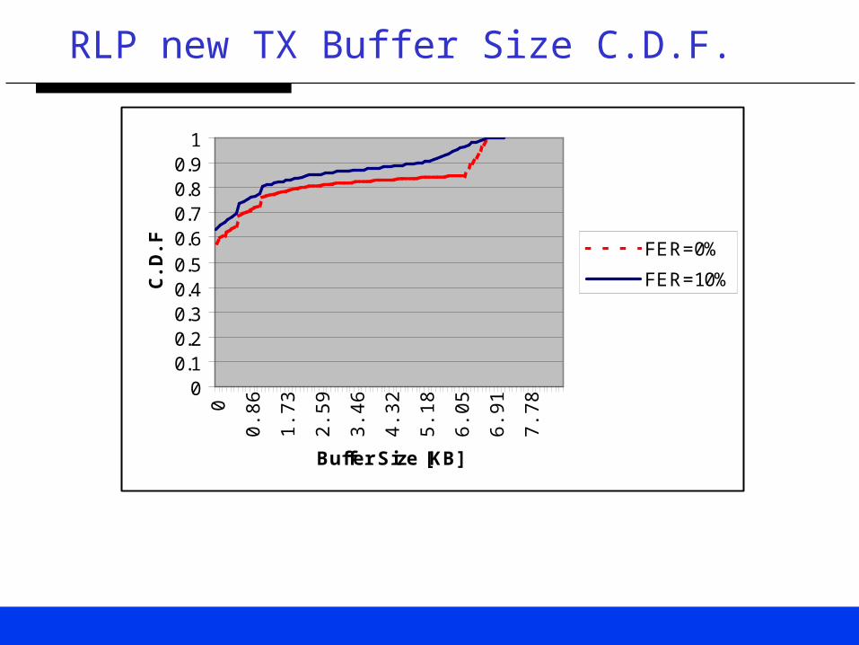
• With a single TCP connection for an HTTP page transfer, the RLP new transmission buffer is empty for 58% and 63% of the time for the case of no errors and FER of 10% respectively.
• This explains the need for packet multiplexing over the air.
• A circuit switched dedicated channel will make inefficient use of the scarce radio bandwidth.

TCP over W-CDMA
draft-inamura-docomo-00.txt
• Choice of MTU size in link layer
• Appropriate receive window size
• Increased initial congestion window
• Use of Selective ACK

Effect of TCP Receive Window
Throughput [Kb/s]
BLER 32KB 64KB 128KB
1% 340 369 369
5% 275 340 340
10% 230 320 320

TCP over W-CDMA
Feature Recommendation
Comments
MTU size 1500B Larger MTU helps TCPwindow grow faster.Small MTU is better forhigh BLERs.
TCP ReceiveWindow size
64KB Going from 64KB to128KB does notimprove performance
TCP InitialWindow
2MSS(up to4380B)
Effective for small datatransfers
Use of SACK Yes Useful when multipleTCP segments are lostin a single window

Summary
• Packet Multiplexing over the air is crucial for efficient support of TCP/IP traffic.
• A radio link layer MUST perform in sequence delivery of radio frames to avoid TCP retransmissions due to duplicate ACKs.
• Multiple instances of link layer protocol per user (e.g., for different TCP flows) will improve the overall system performance (assuming low overhead to setup a radio link connection)

Summary (Continued)
• Minimizing the radio link round trip time (RTT) by eliminating the delays associated with the access network, coding and interleaving etc. will improve the performance of TCP/IP traffic.
• Limit the radio link errors to =< 10%
• Use less aggressive NAK schemes.


