Eurographics Symposium on Geometry Processing 2011Mario Botsch and Scott Schaefer(Guest Editors)
Volume 30 (2011), Number 5
Surface Patches from Unorganized Space Curves
Fatemeh Abbasinejad1, Pushkar Joshi2, Nina Amenta1
1University of California, Davis2Adobe Systems Inc.
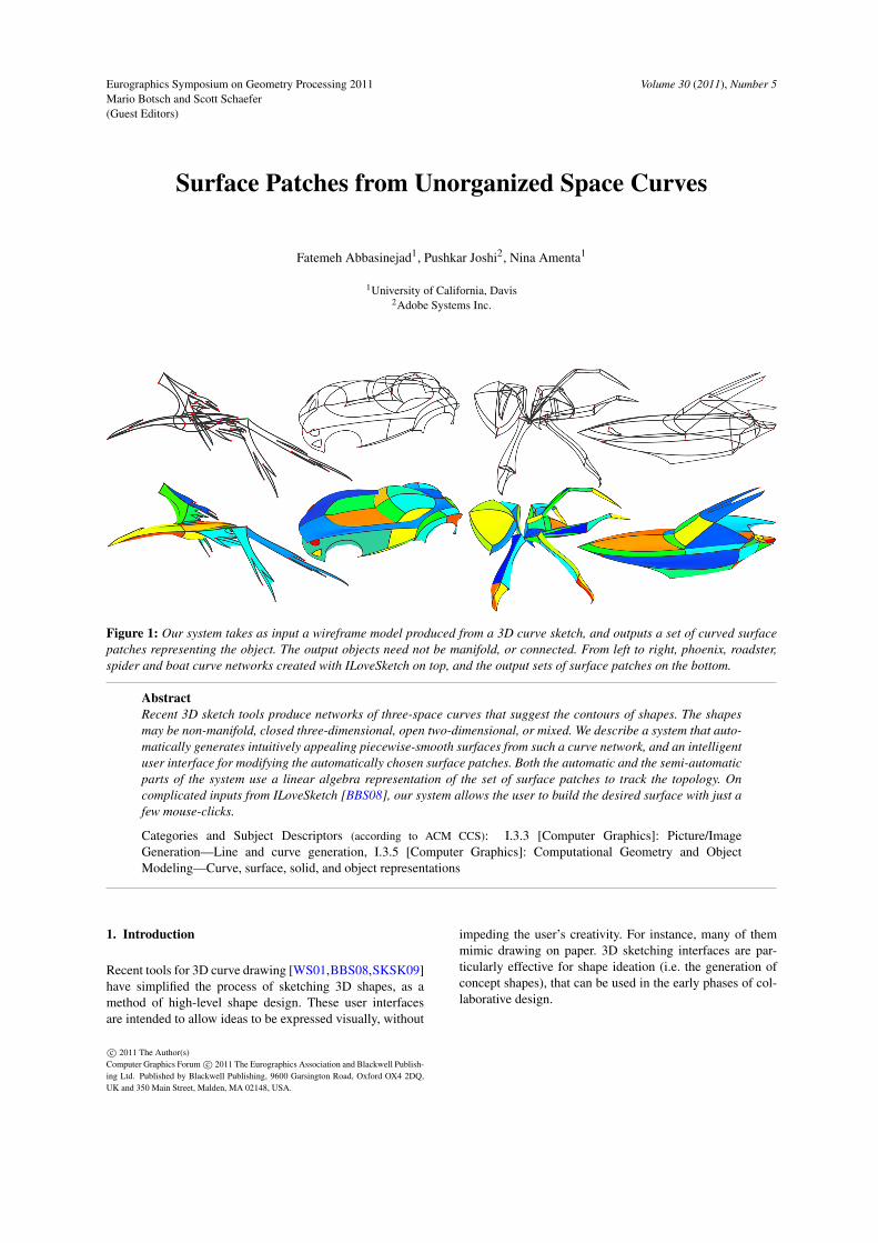
Figure 1: Our system takes as input a wireframe model produced from a 3D curve sketch, and outputs a set of curved surfacepatches representing the object. The output objects need not be manifold, or connected. From left to right, phoenix, roadster,spider and boat curve networks created with ILoveSketch on top, and the output sets of surface patches on the bottom.
AbstractRecent 3D sketch tools produce networks of three-space curves that suggest the contours of shapes. The shapesmay be non-manifold, closed three-dimensional, open two-dimensional, or mixed. We describe a system that auto-matically generates intuitively appealing piecewise-smooth surfaces from such a curve network, and an intelligentuser interface for modifying the automatically chosen surface patches. Both the automatic and the semi-automaticparts of the system use a linear algebra representation of the set of surface patches to track the topology. Oncomplicated inputs from ILoveSketch [BBS08], our system allows the user to build the desired surface with just afew mouse-clicks.
Categories and Subject Descriptors (according to ACM CCS): I.3.3 [Computer Graphics]: Picture/ImageGeneration—Line and curve generation, I.3.5 [Computer Graphics]: Computational Geometry and ObjectModeling—Curve, surface, solid, and object representations
1. Introduction
Recent tools for 3D curve drawing [WS01,BBS08,SKSK09]have simplified the process of sketching 3D shapes, as amethod of high-level shape design. These user interfacesare intended to allow ideas to be expressed visually, without
impeding the user’s creativity. For instance, many of themmimic drawing on paper. 3D sketching interfaces are par-ticularly effective for shape ideation (i.e. the generation ofconcept shapes), that can be used in the early phases of col-laborative design.
c© 2011 The Author(s)Computer Graphics Forum c© 2011 The Eurographics Association and Blackwell Publish-ing Ltd. Published by Blackwell Publishing, 9600 Garsington Road, Oxford OX4 2DQ,UK and 350 Main Street, Malden, MA 02148, USA.
Fatemeh Abbasinejad, Pushkar Joshi, Nina Amenta / Surface Patches from Unorganized Space Curves
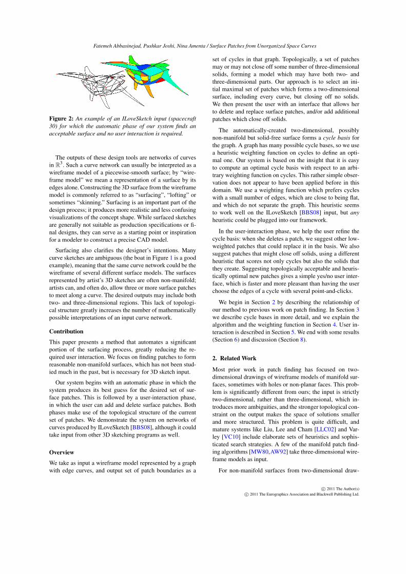
Figure 2: An example of an ILoveSketch input (spacecraft30) for which the automatic phase of our system finds anacceptable surface and no user interaction is required.
The outputs of these design tools are networks of curvesin R3. Such a curve network can usually be interpreted as awireframe model of a piecewise-smooth surface; by “wire-frame model” we mean a representation of a surface by itsedges alone. Constructing the 3D surface from the wireframemodel is commonly referred to as “surfacing”, “lofting” orsometimes “skinning.” Surfacing is an important part of thedesign process; it produces more realistic and less confusingvisualizations of the concept shape. While surfaced sketchesare generally not suitable as production specifications or fi-nal designs, they can serve as a starting point or inspirationfor a modeler to construct a precise CAD model.
Surfacing also clarifies the designer’s intentions. Manycurve sketches are ambiguous (the boat in Figure 1 is a goodexample), meaning that the same curve network could be thewireframe of several different surface models. The surfacesrepresented by artist’s 3D sketches are often non-manifold;artists can, and often do, allow three or more surface patchesto meet along a curve. The desired outputs may include bothtwo- and three-dimensional regions. This lack of topologi-cal structure greatly increases the number of mathematicallypossible interpretations of an input curve network.
Contribution
This paper presents a method that automates a significantportion of the surfacing process, greatly reducing the re-quired user interaction. We focus on finding patches to formreasonable non-manifold surfaces, which has not been stud-ied much in the past, but is necessary for 3D sketch input.
Our system begins with an automatic phase in which thesystem produces its best guess for the desired set of sur-face patches. This is followed by a user-interaction phase,in which the user can add and delete surface patches. Bothphases make use of the topological structure of the currentset of patches. We demonstrate the system on networks ofcurves produced by ILoveSketch [BBS08], although it couldtake input from other 3D sketching programs as well.
Overview
We take as input a wireframe model represented by a graphwith edge curves, and output set of patch boundaries as a
set of cycles in that graph. Topologically, a set of patchesmay or may not close off some number of three-dimensionalsolids, forming a model which may have both two- andthree-dimensional parts. Our approach is to select an ini-tial maximal set of patches which forms a two-dimensionalsurface, including every curve, but closing off no solids.We then present the user with an interface that allows herto delete and replace surface patches, and/or add additionalpatches which close off solids.
The automatically-created two-dimensional, possiblynon-manifold but solid-free surface forms a cycle basis forthe graph. A graph has many possible cycle bases, so we usea heuristic weighting function on cycles to define an opti-mal one. Our system is based on the insight that it is easyto compute an optimal cycle basis with respect to an arbi-trary weighting function on cycles. This rather simple obser-vation does not appear to have been applied before in thisdomain. We use a weighting function which prefers cycleswith a small number of edges, which are close to being flat,and which do not separate the graph. This heuristic seemsto work well on the ILoveSketch [BBS08] input, but anyheuristic could be plugged into our framework.
In the user-interaction phase, we help the user refine thecycle basis: when she deletes a patch, we suggest other low-weighted patches that could replace it in the basis. We alsosuggest patches that might close off solids, using a differentheuristic that scores not only cycles but also the solids thatthey create. Suggesting topologically acceptable and heuris-tically optimal new patches gives a simple yes/no user inter-face, which is faster and more pleasant than having the userchoose the edges of a cycle with several point-and-clicks.
We begin in Section 2 by describing the relationship ofour method to previous work on patch finding. In Section 3we describe cycle bases in more detail, and we explain thealgorithm and the weighting function in Section 4. User in-teraction is described in Section 5. We end with some results(Section 6) and discussion (Section 8).
2. Related Work
Most prior work in patch finding has focused on two-dimensional drawings of wireframe models of manifold sur-faces, sometimes with holes or non-planar faces. This prob-lem is significantly different from ours; the input is strictlytwo-dimensional, rather than three-dimensional, which in-troduces more ambiguities, and the stronger topological con-straint on the output makes the space of solutions smallerand more structured. This problem is quite difficult, andmature systems like Liu, Lee and Cham [LLC02] and Var-ley [VC10] include elaborate sets of heuristics and sophis-ticated search strategies. A few of the manifold patch find-ing algorithms [MW80,AW92] take three-dimensional wire-frame models as input.
For non-manifold surfaces from two-dimensional draw-
c© 2011 The Author(s)c© 2011 The Eurographics Association and Blackwell Publishing Ltd.

Fatemeh Abbasinejad, Pushkar Joshi, Nina Amenta / Surface Patches from Unorganized Space Curves
ings, Shpitalni and Lipson [SL96] proposed a heuristicsearch algorithm, using the constraint that the commonboundary between two faces should always be smooth. Liuand Lee [LL01] sped up their algorithm by finding minimalcycles more efficiently and by formulating a better searchalgorithm, reporting performance similar to ours. Sun andLee [SL04] give some interesting analysis of when a ver-tex, edge or face must be non-manifold. Sketch inputs areless constrained than the simple CAD models considered inthese papers; for some (eg. the phoenix in Figure 1), the de-sired surface has patches adjacent along sharp edges, andin general the inputs are more complex, curved, and moremixed-dimensional.
If the input is a three-connected planar graph, it is pos-sible to find the correct face structure by embedding on thesphere [Han82, DB83, SL96]. Inoue et al. [ISC03] considertwo-connected planar graphs, which can be embedded ontothe sphere in multiple ways; they produce many solutionsand then score them. Many non-manifold models, such asthe roadster in Figure 1, are 2-connected planar graphs. In-oeue’s algorithm would reconstruct them as solids, but possi-bly the algorithm could be adapted to produce non-manifoldsurfaces.
Cycle basis approaches, like ours, have in the past beenapplied to genus-zero manifolds. The algorithm of Gan-ter and Uicker [GU83] starts with an arbitrary cycle ba-sis, and pivots from one cycle basis to better one byadding cycles together as described in Section 3. Brewerand Courter [BC86] also followed this approach, optimiz-ing the basis so that the number of edges shared by cy-cles in the basis is minimized. We tried a pivoting approachbased on their ideas, but found that it often failed to pro-duce a desirable cycle basis. The most relevant prior workis probably by Bagali et al. [BW95], who construct a cy-cle basis using a greedy algorithm. Cycles are added in or-der of smallest total edge length, and the topological as-sumption that the input is a solid of genus zero is used toreject inappropriate choices. There is also theoretical work[GH02, LR05, dP95, KMMP04, BGdV04] on greedily com-puting cycle bases with minimal total edge length. Thesepapers provide polynomial-time algorithms by guarantee-ing that not too many cycles are examined. Along with Var-ley [VC10], we observe that weighting cycles by total edgelength does not seem to lead to good results in patch find-ing. Our main innovation is the observation that weightingcycles, rather than edges, allows us to encode a much moreflexible variety of heuristics into the set of weights, and thatany choice of cycle weights can be easily optimized via thegreedy algorithm.
3. Linear Algebra Framework
Any set of two-dimensional patches forms what is calleda two-dimensional cell complex. If it separates three-spaceinto two or more connected components, we treat all
Figure 3: The matrix representing the four faces of a tetra-hedron. We can verify that the fourth column of the matrixis the sum of the first three, using arithmetic modulo two.We also observe that geometrically the cycle bounding thefourth face is the sum of the first three, and that it closes offa solid (the interior of the tetrahedron). Any choice of threeof these four columns forms a cycle basis (one of many pos-sible cycle bases for this graph). The entire vector space ofcycles defined by the wireframe model would consist of allpossible sums of these four cycles; for example, the cyclea,b,c,d is the sum of a,b, f and f ,c,d.
but the exterior as three-dimensional solids, producing athree-dimensional cell complex (possibly containing two-dimensional as well as three-dimensional parts). Our ap-proach to selecting an initial set of patches is to constructthe largest two-dimensional complex we can before closingoff any solid three-dimensional regions.
Such a set of patches is called a cycle basis for the set ofcycles in the input graph. It is called a basis because the setof cycles - that is, the set of possible patches - forms a vectorspace. This vector space representation (described below) isthe same as that used in topology when computing homologyusing the Smith Normal Form and in persistent homologycomputation [EH08]. It is helpful to think of this structureas an extension to two dimensions of the combinatorics ofspanning trees: a spanning tree in a graph is a maximal setof edges forming no cycles, whereas here we are looking fora maximal set of cycles forming no solids.
A cycle in a graph is a set of edges such that an evennumber of edges meet at each vertex. Notice that under thisdefinition, cycles may have multiple connected components,or vertices of degree greater than two. “Adding" two cyclesconsists of taking their symmetric difference: shared edgesare deleted, and the remaining edges in either cycle are com-bined into the new cycle. A cycle basis C is a set of cyclessuch that every other cycle in the graph can be constructedas a sum of some subset of the cycles in C. See the examplein Figure 3.
Computationally, this is implemented using matrix arith-metic over the integers mod two, also known as the GaloisField of order two, GF(2). The entire vector space could berepresented by a single large matrix M with a row for eachedge of the input graph, and a column for each possible cy-cle. There is a 1 in matrix location mi, j if edge i belongsto cycle j, and 0 otherwise. Adding two cycles c j,ck cor-
c© 2011 The Author(s)c© 2011 The Eurographics Association and Blackwell Publishing Ltd.
Fatemeh Abbasinejad, Pushkar Joshi, Nina Amenta / Surface Patches from Unorganized Space Curves
responds to adding the corresponding columns in GF(2), sothat 1+1= 0; notice that this produces the symmetric differ-ence, which is another cycle cl (i.e. cl = c j + ck). The threecycles c j,ck and cl are dependent, since any one is the sumof the other two. The rank r of M, over GF(2), is the sizeof the largest independent set of columns. As usual, we canselect many possible bases for the vector space M, each ofwhich is a set of columns of size r. For a connected graph,r = m−n+1, where m is the number of edges in the graphand n is the number of vertices, but there is no requirementthat our inputs be connected, and many are not.
4. Automatic Patch Finding
In this section we describe the automatic phase of our patchidentification system. The input to this phase is an undirectedgraph, whose edges are smooth curves. The curves meet at afinite number of vertices, so that two curves may not overlapover a non-negligible length. There may be, and often are,multiple curves connecting the same pair of vertices. Thereis no requirement that the output should be a manifold.
4.1. Algorithm
Just as there are many spanning trees in a graph, there aremany cycle bases; in fact, there are possibly an exponentialnumber of both cycles and cycle bases. Our objective is toselect an optimum cycle basis, where the optimum is definedas the minimum using a heuristic weighting criterion (seeSection 4.2).
To produce the optimal basis, we use the standard greedymatroid algorithm, which can be applied to any vector space,with any weighting function on the elements. We write W (c)to denote the weight of cycle c (or just W instead of W (c)when clear). The weight of a cycle basis {c1, . . . ,cr} is thesum of its cycle weights.
Theorem 1 [Law76] For any weighting function W , thegreedy matroid algorithm produces a minimum-weight ba-sis.
Applied to minimum spanning tree computation, thegreedy matroid algorithm is Kruskal’s algorithm. Applied tocycle basis computation, the greedy matroid algorithm pro-ceeds as follows. We begin with an empty set of cycles C,and at each step we greedily attempt to add the cycle c ofminimum weight W (c). If c is dependent on some subset ofthe cycles in C, we discard it. If, on the other hand, c is in-dependent, we add it to C and continue.
The current set of cycles C is represented as a set of col-umn vectors as described in the previous section, and to seeif a new column vector is independent of the current set, weappend it to the current matrix, and compute the rank. If therank is increased by adding the new column, the new cy-cle is independent of the previous set of cycles. We use theFFLAS-FFPACK package [JGDP04] for linear algebra overfinite fields to compute the rank of the 0−1 matrix.
4.2. Weighting function
Choosing the heuristic weighting function W requires trade-offs between simplicity, efficiency and the quality of the re-sults. Our choice combines three heuristics into a single lex-icographic function W .
Our first heuristic is that we prefer short cycles overlong ones. The second heuristic is borrowed from Bagali etal. [BW95]: non-separating cycles are preferred over sepa-rating cycles. A separating cycle is one for which removal ofthe cycle vertices and all of their adjacent edges (includingthe cycle edges) increases the number of connected compo-nents in the graph.
To combine these two heuristics, we define for each cyclethe quantity
k = number of edges+(2+ ε)s
where s is zero if the cycle is non-separating and one if it isseparating. Ordering the cycles by k means that we try firstnon-separating cycles of length 2,3 and then 4, followed byseparating cycles of length 2, non-separating cycles of length5, separating cycles of length 3, and so on. See Algorithm 1for a bit more detail on how we generate and examine cyclesin this order.
Cycles with the same value of k are ordered geometri-cally, by the volumes of their axis-aligned bounding boxes,from smallest to largest. Since the curves are given as or-dered sets of sample points, the computation of boundingboxes is trivial. This choice favors nearly flat faces whichare well-aligned with the coordinate planes. It works sur-prisingly well on the ILoveSketch [BBS08] data, perhaps be-cause the wireframe models are drawn aligned with the coor-dinate system. More sophisticated geometric heuristics, forinstance, the volume of the approximating ellipsoid foundby PCA, would of course be possible. But the limitationsthat we see in the current system (see Section 8) do not seemto be related to this design choice.
Combined with the fact that we consider the cycles in or-der of edge length, this means that the cycle basis we findoptimizes the following lexicographic objective function W :it finds a basis with minimum total summed value of k, andof the many bases with that total sum of k, it finds one thatminimizes the sum of the volumes of the bounding boxes.
5. Topology-aware User Interface
Our user interface allows the user to both add patches toclose solids, and to delete patches, replacing them with alter-native choices. The naive user interface for deletion is fine:point at the patch, and click to delete it. But to add a patch,either to close a solid or to replace a deleted patch, the naiveuser interface is to indicate a sequence of edges, requiringseveral delicate point-and-clicks, each taking a second or so.This rapidly becomes tedious, which is the reason that au-tomatic patch finding is desirable at all. Since some user
c© 2011 The Author(s)c© 2011 The Eurographics Association and Blackwell Publishing Ltd.
Fatemeh Abbasinejad, Pushkar Joshi, Nina Amenta / Surface Patches from Unorganized Space Curves
Algorithm 1 Finding an optimal cycle basis1: {INPUT: Graph [V,E]}2: {OUTPUT: Cycle basis represented by matrix C }3: C = [] {empty matrix}4: for all i ∈ {2, . . . ,n} do5: for all v ∈V do6: Find all cycles of length i containing v, by breadth-
first search.7: Store separating cycles in set Si, and non-
separating cycles in set Ni, removing duplicates.8: end for9: Rank the cycles in Ni by bounding box volume.
10: for all cycles c ∈ Ni, in rank order do11: Add vector representation of c to C.12: Compute rank of new matrix C.13: If rank did not increase, remove c and discard.14: end for15: if i≥ 4 then16: Rank the cycles in Si−2 by bounding box volume.17: for all cycles c ∈ Si−2, in rank order do18: Add vector representation of c to C.19: Compute rank of new matrix C.20: If rank did not increase, remove c and discard.21: end for22: end if23: end for
interaction cannot be completely avoided, we use geomet-ric/topological analysis to provide a better, semi-automateduser interface. In our interface, we show the user patches thatshe might want to add, each of which can be accepted or re-jected with a single click, in a small fraction of a second.The user can always fall back to the naive interface, but wedid this for only two of the 34 models we have built.
Deleting a patch leaves an incomplete cycle basis. As a re-placement patch, we suggest the next-best patch again usingthe heuristic weighting function of Section 4.2.
Adding a patch to a set of cycles of full rank closes off anew solid. Our system suggest closing patches using a dif-ferent set of heuristics, which consider the solids as well asthe cycles. The first heuristic is again to prefer adding cy-cles with few edges. Second, we prefer a patch c which in-cludes many edges of degree one, and makes them degreetwo in the closed model; a simple example would be the fi-nal square patch closing off a cube. Third, we use the heuris-tic that the area of the patch c closing off the solid shouldbe small relative to the area of the solid itself. This favorslarger solids, while not allowing large solids to be created byadding large patches. We use the area of the largest side ofthe axis-aligned bounding box of a patch as an estimate of itsarea, since it is not easy to compute the area of a non-planarpatch. Again, we found that using the bounding box workssurprisingly well.
To detect the new solid potentially formed by the addi-tion of cycle c, we again use the linear algebra mechanicsof Section 3. Let C be the matrix of rank r whose columnrepresent the current cycle basis (irrespective of whether themodel currently includes some solids already). We removeeach cycle ci in turn from C, and then consider the rank ofC− ci + c. If the rank is r, we know that ci would completea cycle containing c, and if the rank is r− 1, we know thatthe cycle containing c is included in the set C− ci.
We combine the three heuristics in the following formula,where cycles producing a large value of Ws(c) are preferred:
Ws(c) = 10∗ (a+b)+ k
where a is the ratio total area estimate of solid s / area es-timate of cycle c (i.e. the third heuristic), b is the number ofedges in c that have degree one in the current model (i.e. thesecond heuristic), and k is the number of edges in cycle c.
6. Results
As mentioned before, we demonstrate our method by find-ing patches in sample 3D wireframe models from ILoveS-ketch [BBS08].
6.1. Pre-processing
The ILoveSketch [BBS08] output consists of unorientedpiecewise-linear curves (although the user enters curves witha specific orientation, we do not assume that this is mean-ingful), represented as sequences of points. Intersections arenot indicated, and in fact for most of the sketches the curvesfail to intersect each other at all. To produce a graph, weassume that two curves intersect when they pass within auser-defined threshold, and place the intersection at the clos-est point. The threshold varies because different models aremore or less carefully drawn. When an intersection is foundthe curves are automatically snapped together, with the dis-placement interpolated across the edge to avoid introducingsharp bends. We introduced some intersections which werenot found automatically, using Maya, so that we could getall of the visually more interesting models. Dangling edges(with a vertex of degree one) were removed. We assume thatthe input curves are intended to be smooth, and we interpretsharp corners within a curve as vertices of degree two. With-out too much trouble, we turned 49 ILoveSketch models intoreasonable input graphs.
In a complete sketch-based modeling system where a sur-facing algorithm such as ours would be used, the curvedrawing interface should probably include snapping of in-tersection points, which would obviate much of this pre-processing.
6.2. Results
Of the 49 input graphs we could use, we successfully pro-duced sets of surface patches from 34 of them. We defined a
c© 2011 The Author(s)c© 2011 The Eurographics Association and Blackwell Publishing Ltd.
Fatemeh Abbasinejad, Pushkar Joshi, Nina Amenta / Surface Patches from Unorganized Space Curves
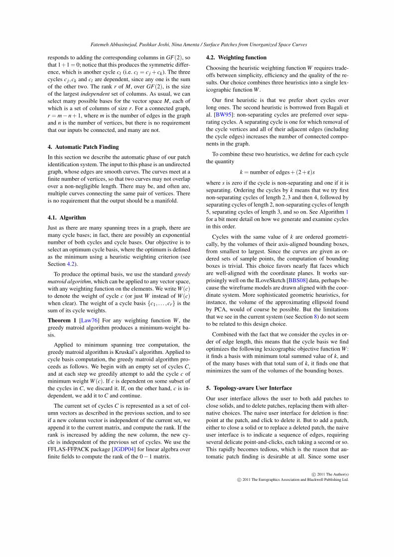
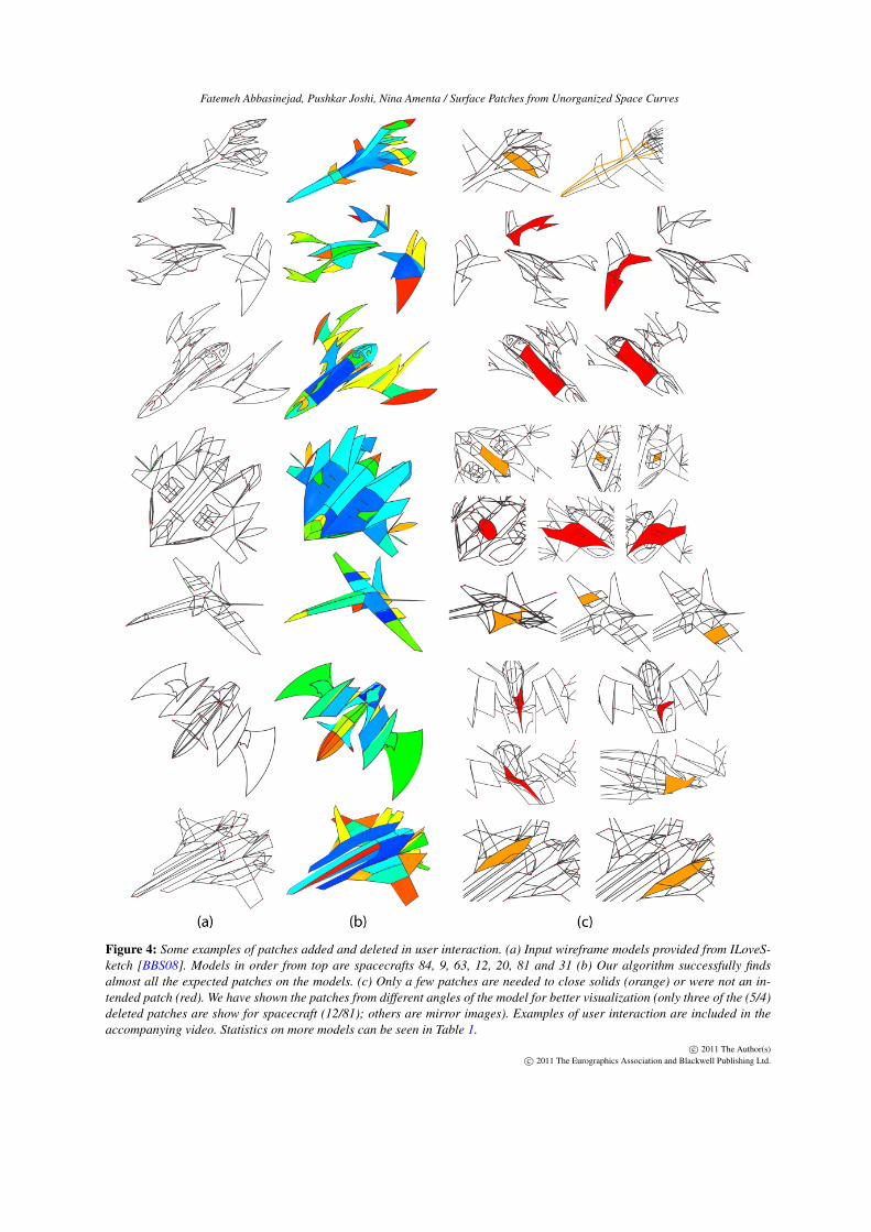
Figure 4: Some examples of patches added and deleted in user interaction. (a) Input wireframe models provided from ILoveS-ketch [BBS08]. Models in order from top are spacecrafts 84, 9, 63, 12, 20, 81 and 31 (b) Our algorithm successfully findsalmost all the expected patches on the models. (c) Only a few patches are needed to close solids (orange) or were not an in-tended patch (red). We have shown the patches from different angles of the model for better visualization (only three of the (5/4)deleted patches are show for spacecraft (12/81); others are mirror images). Examples of user interaction are included in theaccompanying video. Statistics on more models can be seen in Table 1.
c© 2011 The Author(s)c© 2011 The Eurographics Association and Blackwell Publishing Ltd.
Fatemeh Abbasinejad, Pushkar Joshi, Nina Amenta / Surface Patches from Unorganized Space Curves
Total Patch # Patches
Model #Curves Time Time Auto. Manual(sec.) (sec.)
Jetfighter 65 5 1 23 2 add 1 del.Spacecraft19 65 4 1 26 2 add 2 del.Spacecraft26 66 14 1 24 2 addSpacecraft56 74 4 2 20 1 del.Speaker 76 23 2 27 1 addSpacecraft20 77 13 3 34 3 addPhoenix 80 3 ~0 17 1 addSpacecraft37 81 6 1 23 1 add 2 del.Spacecraft9 86 3 1 37 2 del.Roadster 86 18 1 31 -Spacecraft75 88 9 1 22 1 del.Spacecraft13 89 17 4 30 2 addSpacecraft59 90 10 3 32 4 del.Spacecraft36 95 18 5 34 1 addSpacecraft38 95 23 6 36 2 del.Boat 94 36 9 37 1 add 6 del.Spacecraft57 107 14 6 37 -Spacecraft84 108 33 9 42 2 addSpacecraft33 109 20 8 38 1 add 2 del.Spacecraft44 110 47 19 48 1 add 2 del.Spacecraft77 111 12 4 31 -Spacecraft81 111 28 12 43 1 add 4 del.Spacecraft63 117 7 2 34 2 del.Spacecraft85 126 167 16 54 3 add 2 del.Spacecraft92 127 13 6 50 2 add 8 del.Spacecraft30 132 69 30 50 -Spacecraft49 139 9 4 39 5 add 8 del.Spider 139 22 15 71 8 addSpacecraft87 139 34 20 52 6 add 6 del.Spacecraft90 140 30 15 45 2 add 3 del.Spacecraft31 142 43 16 44 2 addSpacecraft10 146 14 6 40 -Spacecraft88 162 124 85 71 3 add 4 del.Spacecraft12 196 66 51 70 3 add 5 del.
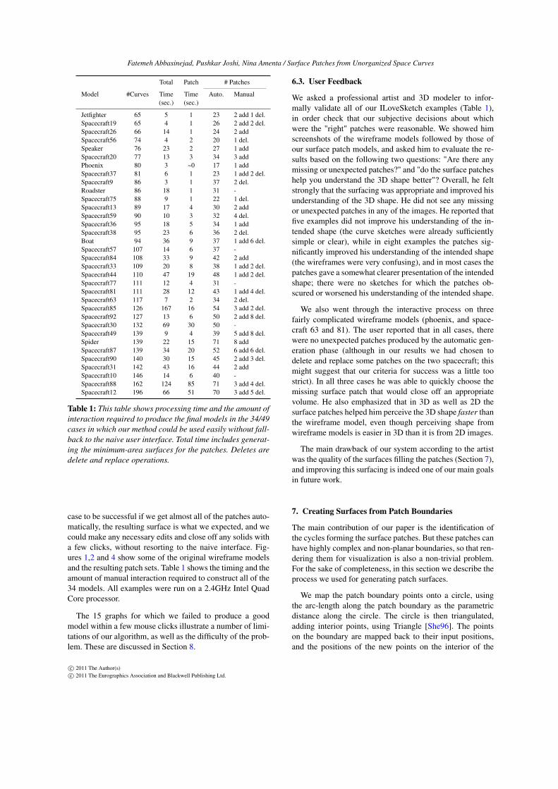
Table 1: This table shows processing time and the amount ofinteraction required to produce the final models in the 34/49cases in which our method could be used easily without fall-back to the naive user interface. Total time includes generat-ing the minimum-area surfaces for the patches. Deletes aredelete and replace operations.
case to be successful if we get almost all of the patches auto-matically, the resulting surface is what we expected, and wecould make any necessary edits and close off any solids witha few clicks, without resorting to the naive interface. Fig-ures 1,2 and 4 show some of the original wireframe modelsand the resulting patch sets. Table 1 shows the timing and theamount of manual interaction required to construct all of the34 models. All examples were run on a 2.4GHz Intel QuadCore processor.
The 15 graphs for which we failed to produce a goodmodel within a few mouse clicks illustrate a number of limi-tations of our algorithm, as well as the difficulty of the prob-lem. These are discussed in Section 8.
6.3. User Feedback
We asked a professional artist and 3D modeler to infor-mally validate all of our ILoveSketch examples (Table 1),in order check that our subjective decisions about whichwere the "right" patches were reasonable. We showed himscreenshots of the wireframe models followed by those ofour surface patch models, and asked him to evaluate the re-sults based on the following two questions: "Are there anymissing or unexpected patches?" and "do the surface patcheshelp you understand the 3D shape better"? Overall, he feltstrongly that the surfacing was appropriate and improved hisunderstanding of the 3D shape. He did not see any missingor unexpected patches in any of the images. He reported thatfive examples did not improve his understanding of the in-tended shape (the curve sketches were already sufficientlysimple or clear), while in eight examples the patches sig-nificantly improved his understanding of the intended shape(the wireframes were very confusing), and in most cases thepatches gave a somewhat clearer presentation of the intendedshape; there were no sketches for which the patches ob-scured or worsened his understanding of the intended shape.
We also went through the interactive process on threefairly complicated wireframe models (phoenix, and space-craft 63 and 81). The user reported that in all cases, therewere no unexpected patches produced by the automatic gen-eration phase (although in our results we had chosen todelete and replace some patches on the two spacecraft; thismight suggest that our criteria for success was a little toostrict). In all three cases he was able to quickly choose themissing surface patch that would close off an appropriatevolume. He also emphasized that in 3D as well as 2D thesurface patches helped him perceive the 3D shape faster thanthe wireframe model, even though perceiving shape fromwireframe models is easier in 3D than it is from 2D images.
The main drawback of our system according to the artistwas the quality of the surfaces filling the patches (Section 7),and improving this surfacing is indeed one of our main goalsin future work.
7. Creating Surfaces from Patch Boundaries
The main contribution of our paper is the identification ofthe cycles forming the surface patches. But these patches canhave highly complex and non-planar boundaries, so that ren-dering them for visualization is also a non-trivial problem.For the sake of completeness, in this section we describe theprocess we used for generating patch surfaces.
We map the patch boundary points onto a circle, usingthe arc-length along the patch boundary as the parametricdistance along the circle. The circle is then triangulated,adding interior points, using Triangle [She96]. The pointson the boundary are mapped back to their input positions,and the positions of the new points on the interior of the
c© 2011 The Author(s)c© 2011 The Eurographics Association and Blackwell Publishing Ltd.
Fatemeh Abbasinejad, Pushkar Joshi, Nina Amenta / Surface Patches from Unorganized Space Curves
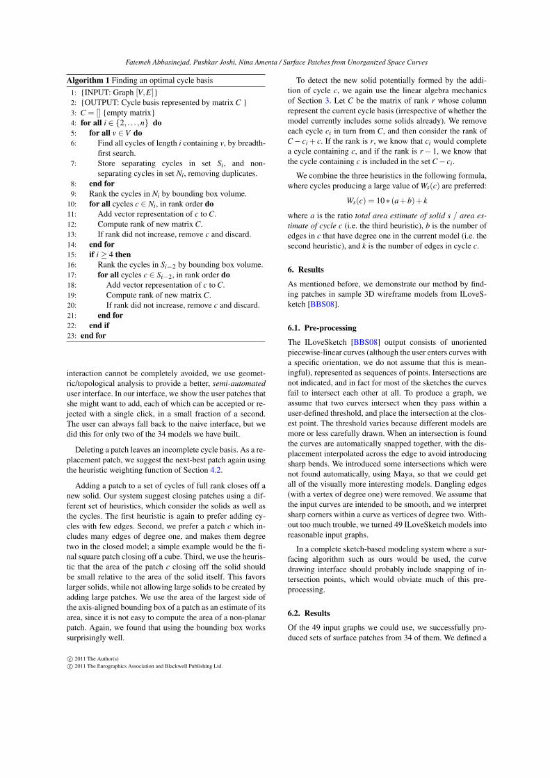
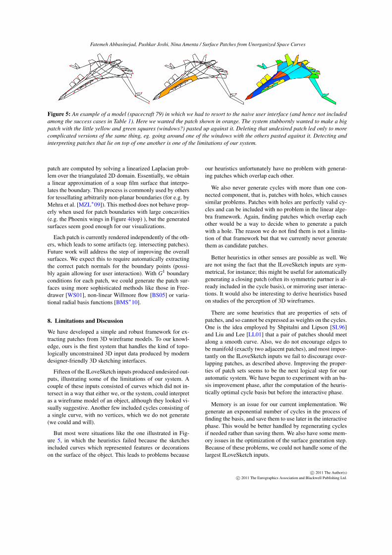
Figure 5: An example of a model (spacecraft 79) in which we had to resort to the naive user interface (and hence not includedamong the success cases in Table 1). Here we wanted the patch shown in orange. The system stubbornly wanted to make a bigpatch with the little yellow and green squares (windows?) pasted up against it. Deleting that undesired patch led only to morecomplicated versions of the same thing, eg. going around one of the windows with the others pasted against it. Detecting andinterpreting patches that lie on top of one another is one of the limitations of our system.
patch are computed by solving a linearized Laplacian prob-lem over the triangulated 2D domain. Essentially, we obtaina linear approximation of a soap film surface that interpo-lates the boundary. This process is commonly used by othersfor tessellating arbitrarily non-planar boundaries (for e.g. byMehra et al. [MZL∗09]). This method does not behave prop-erly when used for patch boundaries with large concavities(e.g. the Phoenix wings in Figure 4(top) ), but the generatedsurfaces seem good enough for our visualizations.
Each patch is currently rendered independently of the oth-ers, which leads to some artifacts (eg. intersecting patches).Future work will address the step of improving the overallsurfaces. We expect this to require automatically extractingthe correct patch normals for the boundary points (possi-bly again allowing for user interaction). With G1 boundaryconditions for each patch, we could generate the patch sur-faces using more sophisticated methods like those in Free-drawer [WS01], non-linear Willmore flow [BS05] or varia-tional radial basis functions [BMS∗10].
8. Limitations and Discussion
We have developed a simple and robust framework for ex-tracting patches from 3D wireframe models. To our knowl-edge, ours is the first system that handles the kind of topo-logically unconstrained 3D input data produced by moderndesigner-friendly 3D sketching interfaces.
Fifteen of the ILoveSketch inputs produced undesired out-puts, illustrating some of the limitations of our system. Acouple of these inputs consisted of curves which did not in-tersect in a way that either we, or the system, could interpretas a wireframe model of an object, although they looked vi-sually suggestive. Another few included cycles consisting ofa single curve, with no vertices, which we do not generate(we could and will).
But most were situations like the one illustrated in Fig-ure 5, in which the heuristics failed because the sketchesincluded curves which represented features or decorationson the surface of the object. This leads to problems because
our heuristics unfortunately have no problem with generat-ing patches which overlap each other.
We also never generate cycles with more than one con-nected component, that is, patches with holes, which causessimilar problems. Patches with holes are perfectly valid cy-cles and can be included with no problem in the linear alge-bra framework. Again, finding patches which overlap eachother would be a way to decide when to generate a patchwith a hole. The reason we do not find them is not a limita-tion of that framework but that we currently never generatethem as candidate patches.
Better heuristics in other senses are possible as well. Weare not using the fact that the ILoveSketch inputs are sym-metrical, for instance; this might be useful for automaticallygenerating a closing patch (often its symmetric partner is al-ready included in the cycle basis), or mirroring user interac-tions. It would also be interesting to derive heuristics basedon studies of the perception of 3D wireframes.
There are some heuristics that are properties of sets ofpatches, and so cannot be expressed as weights on the cycles.One is the idea employed by Shpitalni and Lipson [SL96]and Liu and Lee [LL01] that a pair of patches should meetalong a smooth curve. Also, we do not encourage edges tobe manifold (exactly two adjacent patches), and most impor-tantly on the ILoveSketch inputs we fail to discourage over-lapping patches, as described above. Improving the proper-ties of patch sets seems to be the next logical step for ourautomatic system. We have begun to experiment with an ba-sis improvement phase, after the computation of the heuris-tically optimal cycle basis but before the interactive phase.
Memory is an issue for our current implementation. Wegenerate an exponential number of cycles in the process offinding the basis, and save them to use later in the interactivephase. This would be better handled by regenerating cyclesif needed rather than saving them. We also have some mem-ory issues in the optimization of the surface generation step.Because of these problems, we could not handle some of thelargest ILoveSketch inputs.
c© 2011 The Author(s)c© 2011 The Eurographics Association and Blackwell Publishing Ltd.
Fatemeh Abbasinejad, Pushkar Joshi, Nina Amenta / Surface Patches from Unorganized Space Curves
Acknowledgments
This project was supported by NSF Grant IS-0964357 andAdobe Collaborative Research Funding, for which we aregrateful. We thank Dan Anthony Alcantara for help with thevideo, Dmitry Morozov for topological advice, and DanielPresedo from the Photoshop group at Adobe for doing theinformal evaluation.
References[AW92] AGARWAL S. C., WAGGENSPACK W. N.: Decomposi-
tion method for extracting face topologies from wireframe mod-els. Computer-Aided Design 24, 3 (1992), 123 – 140. 2
[BBS08] BAE S.-H., BALAKRISHNAN R., SINGH K.: Iloves-ketch: as-natural-as-possible sketching system for creating 3dcurve models. In Proceedings of the 21st annual ACM Sympo-sium on User Interface Software and Technology (New York, NY,USA, 2008), UIST ’08, ACM, pp. 151–160. 1, 2, 4, 5, 6
[BC86] BREWER III J. A., COURTER S. M.: Automated con-version of curvilinear wire-frame models to surface boundarymodels; a topological approach. In Proceedings of of ACM SIG-GRAPH 1986 (New York, NY, USA, 1986), SIGGRAPH ’86,ACM, pp. 171–178. 3
[BGdV04] BERGER F., GRITZMANN P., DE VRIES S.: Minimumcycle bases for network graphs. Algorithmica 40 (June 2004),51–62. 3
[BMS∗10] BRAZIL E. V., MACEDO I., SOUSA M. C.,DE FIGUEIREDO L. H., VELHO L.: Sketching varia-tional hermite-rbf implicits. In Proceedings of the SeventhSketch-Based Interfaces and Modeling Symposium (Aire-la-Ville, Switzerland, Switzerland, 2010), SBIM ’10, EurographicsAssociation, pp. 1–8. 8
[BS05] BOBENKO A. I., SCHRÖDER P.: Discrete willmore flow.In Proceedings of the third Eurographics Symposium on Geom-etry processing (Aire-la-Ville, Switzerland, Switzerland, 2005),SGP ’05, Eurographics Association, pp. 101–110. 8
[BW95] BAGALI S., WAGGENSPACK JR. W. N.: A shortest pathapproach to wireframe to solid model conversion. In Proceedingsof the third ACM Symposium on Solid modeling and applications(New York, NY, USA, 1995), SMA ’95, ACM, pp. 339–350. 3,4
[DB83] DUTTON R. D., BRIGHAM R. C.: Efficiently identify-ing the faces of a solid. Computers & Graphics in MechanicalEngineering 7, 2 (1983), 143 – 147. 3
[dP95] DE PINA J.: Applications of Shortest Path Methods. PhDthesis, University of Amsterdam, 1995. 3
[EH08] EDESBRUNNER H., HARER J.: Persistent homology -a survey. In Surveys on Discrete and Computational Geome-try: Twenty Years Later, no. 453 in Contemporary Mathematics.American Mathematical Society, 2008. 3
[GH02] GOLYNSKI A., HORTON J.: A polynomial time algo-rithm to find the minimum cycle basis of a regular matroid. InProceedings of the 8th Scandinavian Workshop on AlgorithmTheory (2002), Penttonen M., Schmidt E. M., (Eds.), no. 2368in SWAT ’02, Springer Berlin / Heidelberg, pp. 200–209. 3
[GU83] GANTER M. A., UICKER J. J.: From Wire-Frame tosolid geometric: Automated conversion of data representations.Computers in Mechanical Engineering 2 (sept 1983), 40–45. 3
[Han82] HANRAHAN P. M.: Creating volume models from edge-vertex graphs. In Proceedings of ACM SIGGRAPH 1982 (NewYork, NY, USA, 1982), SIGGRAPH ’82, ACM, pp. 77–84. 3
[ISC03] INOUE K., SHIMADA K., CHILAKA K.: Solid model re-construction of wireframe cad models based on topological em-beddings of planar graphs. Journal of Mechanical Design 125, 3(2003), 434–442. 3
[JGDP04] JEAN-GUILLAUME DUMAS P. G., PERNET C.: Ff-pack: Finite field linear algebra package. In ISSAC : InternationalSymposium on Symbolic and Algebraic Computations (2004). 4
[KMMP04] KAVITHA T., MEHLHORN K., MICHAIL D.,PALUCH K.: A faster algorithm for minimum cycle basis ofgraphs. In Automata, Languages and Programming (2004), et al.J. D., (Ed.), vol. 3142 of Lecture Notes in Computer Science,Springer Berlin / Heidelberg, pp. 97–109. 3
[Law76] LAWLER E.: Combinatorial Optimization: Networksand Matroids. Holt, Reinhart and Winston, 1976. 4
[LL01] LIU J., LEE Y. T.: Graph-based method for face iden-tification from a single 2d line drawing. Pattern Analysis andMachine Intelligence, IEEE Transactions on 23, 10 (oct 2001),1106 –1119. 3, 8
[LLC02] LIU J., LEE Y. T., CHAM W.-K.: Identifying faces ina 2d line drawing representing a manifold object. Pattern Analy-sis and Machine Intelligence, IEEE Transactions on 24, 12 (dec2002), 1579 – 1593. 2
[LR05] LIEBCHEN C., RIZZI R.: A greedy approach to computea minimum cycle basis of a directed graph. Information Process-ing Letters 94, 3 (2005), 107 – 112. 3
[MW80] MARKOWSKY G., WESLEY M. A.: Fleshing out wireframes. IBM J. Res. Dev. 24 (September 1980), 582–597. 2
[MZL∗09] MEHRA R., ZHOU Q., LONG J., SHEFFER A.,GOOCH A., MITRA N. J.: Abstraction of man-made shapes.In Proceedings of ACM SIGGRAPH Asia 2009 (New York, NY,USA, 2009), SIGGRAPH Asia ’09, ACM, pp. 137:1–137:10. 8
[She96] SHEWCHUK J. R.: Triangle: Engineering a 2D QualityMesh Generator and Delaunay Triangulator. In Applied Compu-tational Geometry: Towards Geometric Engineering, vol. 1148of Lecture Notes in Computer Science. Springer-Verlag, May1996, pp. 203–222. From the First ACM Workshop on AppliedComputational Geometry. 7
[SKSK09] SCHMIDT R., KHAN A., SINGH K., KURTENBACHG.: Analytic drawing of 3D scaffolds. In Proceedings ofACM SIGGRAPH Asia 2009 (New York, NY, USA, 2009), SIG-GRAPH Asia ’09, ACM, pp. 149:1–149:10. 1
[SL96] SHPITALNI M., LIPSON H.: Identification of faces in a2D line drawing projection of a wireframe object. Pattern Anal-ysis and Machine Intelligence, IEEE Transactions on 18, 10 (oct1996), 1000 –1012. 3, 8
[SL04] SUN Y., LEE Y. T.: Topological analysis of a single linedrawing for 3d shape recovery. In Proceedings of the 2nd inter-national conference on Computer graphics and interactive tech-niques in Australasia and South East Asia (2004), GRAPHITE’04, pp. 167–172. 3
[VC10] VARLEY P. A., COMPANY P. P.: A new algorithmfor finding faces in wireframes. Computer-Aided Design 42, 4(2010), 279 – 309. 2, 3
[WS01] WESCHE G., SEIDEL H.-P.: Freedrawer: a free-formsketching system on the responsive workbench. In Proceedingsof the ACM Symposium on Virtual reality software and technol-ogy (New York, NY, USA, 2001), VRST ’01, ACM, pp. 167–174.1, 8
c© 2011 The Author(s)c© 2011 The Eurographics Association and Blackwell Publishing Ltd.


