
SIMATIC HMI
WinCC V7.3WinCC: Communication
System Manual
Print of the Online Help
06/2014A5E34374800-AA
Process communication 1
Allen Bradley - Ethernet IP 2
Mitsubishi Ethernet 3
Modbus TCPIP 4
OPC Channel 5
OPC - Open Connectivity 6
PROFIBUS FMS 7
S5 Ethernet Layer 4 8
S5 PROFIBUS FDL 9
S5 Programmers Port AS511 10
S5 Serial 3964R 11
SIMATIC S7 Protocol Suite 12
SIMATIC S7-1200, S7-1500 Channel
13
SIMATIC TI Ethernet Layer 4 14
SIMATIC TI Serial 15
SIMOTION 16
System Info 17
Communication - Diagnostics 18

Legal informationWarning notice system
This manual contains notices you have to observe in order to ensure your personal safety, as well as to prevent damage to property. The notices referring to your personal safety are highlighted in the manual by a safety alert symbol, notices referring only to property damage have no safety alert symbol. These notices shown below are graded according to the degree of danger.
DANGER
indicates that death or severe personal injury will result if proper precautions are not taken.
WARNING
indicates that death or severe personal injury may result if proper precautions are not taken.
CAUTION
indicates that minor personal injury can result if proper precautions are not taken.
NOTICEindicates that property damage can result if proper precautions are not taken.If more than one degree of danger is present, the warning notice representing the highest degree of danger will be used. A notice warning of injury to persons with a safety alert symbol may also include a warning relating to property damage.
Qualified PersonnelThe product/system described in this documentation may be operated only by personnel qualified for the specific task in accordance with the relevant documentation, in particular its warning notices and safety instructions. Qualified personnel are those who, based on their training and experience, are capable of identifying risks and avoiding potential hazards when working with these products/systems.
Proper use of Siemens productsNote the following:
WARNING
Siemens products may only be used for the applications described in the catalog and in the relevant technical documentation. If products and components from other manufacturers are used, these must be recommended or approved by Siemens. Proper transport, storage, installation, assembly, commissioning, operation and maintenance are required to ensure that the products operate safely and without any problems. The permissible ambient conditions must be complied with. The information in the relevant documentation must be observed.
TrademarksAll names identified by ® are registered trademarks of Siemens AG. The remaining trademarks in this publication may be trademarks whose use by third parties for their own purposes could violate the rights of the owner.
Disclaimer of LiabilityWe have reviewed the contents of this publication to ensure consistency with the hardware and software described. Since variance cannot be precluded entirely, we cannot guarantee full consistency. However, the information in this publication is reviewed regularly and any necessary corrections are included in subsequent editions.
Siemens AGIndustry SectorPostfach 48 4890026 NÜRNBERGGERMANY
A5E34374800-AAⓅ 08/2014 Subject to change
Copyright © Siemens AG 2014.All rights reserved

Table of contents
1 Process communication.............................................................................................................................13 1.1 Communication Basics................................................................................................................13 1.2 Basic Rules for Configuring Connections....................................................................................14 1.3 WinCC process communication..................................................................................................15 1.3.1 WinCC process communication..................................................................................................15 1.3.2 Principle of WinCC communication.............................................................................................15 1.3.3 External tags...............................................................................................................................17 1.3.3.1 External tags...............................................................................................................................17 1.3.3.2 How to Create a New Connection...............................................................................................19 1.3.3.3 An external tag is configured as follows......................................................................................20 1.3.3.4 Format adaptation sorted by WinCC data type...........................................................................21 1.3.3.5 Format adaptation sorted by AS data type..................................................................................27 1.3.3.6 Principle of the BinWrite-Mechanism..........................................................................................35 1.3.3.7 How to Configure a Tag with "BinWrite"......................................................................................37 1.3.4 Port Addresses for Coupling via Ethernet...................................................................................39
2 Allen Bradley - Ethernet IP.........................................................................................................................41 2.1 WinCC Channel "Allen Bradley - Ethernet IP".............................................................................41 2.2 Channel Unit Assignment............................................................................................................42 2.3 Supported Data Types................................................................................................................43 2.4 Configuring the Channel..............................................................................................................44 2.4.1 Configuring the Channel "Allen Bradley - Ethernet IP"................................................................44 2.4.2 How to configure a "Allen Bradley E/IP PLC5" channel unit connection.....................................45 2.4.3 How to configure an "Allen Bradley E/IP SLC50x" channel unit connection...............................46 2.4.4 How to configure an "Allen Bradley E/IP ControlLogix" channel unit connection........................47 2.4.5 Examples: Communication path .................................................................................................48 2.4.6 Configuring the tags....................................................................................................................48 2.4.6.1 Configuring the tags....................................................................................................................48 2.4.6.2 Addressing..................................................................................................................................50 2.4.6.3 Addressing syntax.......................................................................................................................51 2.4.6.4 Addressing Types........................................................................................................................52 2.4.6.5 Examples for Addressing............................................................................................................53 2.4.6.6 How to configure a tag for the Allen Bradley E/IP ControlLogix channel unit.............................54 2.4.6.7 How to configure a tag with bit by bit access for Allen Bradley E/IP PLC5 or SLC50x...............55 2.4.6.8 How to configure a tag with byte by byte access for Allen Bradley E/IP PLC5 or SLC50x.........56 2.4.6.9 How to configure a tag with word by word access for Allen Bradley E/IP PLC5 or SLC50x. ......56 2.4.6.10 How to configure a text tag for Allen Bradley E/IP PLC5 or SLC50x..........................................57
3 Mitsubishi Ethernet.....................................................................................................................................59 3.1 WinCC channel "Mitsubishi Ethernet".........................................................................................59 3.2 Supported data types..................................................................................................................60 3.3 Configuring the Channel..............................................................................................................61
WinCC: CommunicationSystem Manual, 06/2014, A5E34374800-AA 3

3.3.1 Configuring the "Mitsubishi Ethernet" channel............................................................................61 3.3.2 How to configure a "Mitsubishi FX3U Series" channel unit connection.......................................61 3.3.3 How to configure a "Mitsubishi Q Series" channel unit connection.............................................63 3.3.4 Configuring the tags....................................................................................................................64 3.3.4.1 Configuring the tags....................................................................................................................64 3.3.4.2 How to configure a tag................................................................................................................66
4 Modbus TCPIP...........................................................................................................................................69 4.1 "Modbus TCP/IP" channel...........................................................................................................69 4.2 Supported Data Types................................................................................................................70 4.3 Configuring the Channel..............................................................................................................71 4.3.1 Configuring the "Modbus TCPIP" Channel..................................................................................71 4.3.2 How to configure a connection....................................................................................................71 4.3.3 Configuring the tags....................................................................................................................73 4.3.3.1 Configuring the tags....................................................................................................................73 4.3.3.2 How to Configure a Tag with Bit by Bit Access...........................................................................75 4.3.3.3 How to Configure a Tag with Word by Word Access..................................................................76 4.3.3.4 How to Configure a Text Tag......................................................................................................77
5 OPC Channel.............................................................................................................................................79 5.1 WinCC OPC Channel..................................................................................................................79 5.2 OPC Item Manager.....................................................................................................................81 5.3 Overview of the Supported WinCC Data Types..........................................................................85 5.4 WinCC OPC DA Client................................................................................................................86 5.4.1 Functionality of the WinCC OPC DA Client.................................................................................86 5.4.2 How to Access a WinCC Tag with the OPC Item Manager.........................................................87 5.4.2.1 How to Access a WinCC Tag with the OPC Item Manager.........................................................87 5.4.2.2 Configuring the OPC Channel on the WinCC OPC DA Client....................................................88 5.4.2.3 Configuring Access with the OPC Item Manager........................................................................89 5.4.3 Accessing a WinCC Tag without the OPC Item Manager...........................................................93 5.4.4 Using Structures on a WinCC OPC DA Client............................................................................95 5.4.4.1 How to Use Structures on the WinCC OPC DA Client................................................................95 5.4.4.2 Configuring Structures and Structure Tags on the WinCC OPC DA Server...............................96 5.4.4.3 How to Configure Structures on the WinCC OPC DA Client.......................................................97 5.4.5 Error Handling in the Event of Disturbed OPC DA Communication............................................98 5.4.5.1 Error Handling in the Event of Disturbed OPC Communication..................................................98 5.4.5.2 WinCC as OPC DA Server..........................................................................................................99 5.4.5.3 WinCC as OPC DA Client.........................................................................................................101 5.5 WinCC OPC XML Client............................................................................................................103 5.5.1 Functionality of the WinCC OPC XML Client............................................................................103 5.5.2 How to Access a WinCC Tag with the OPC Item Manager.......................................................104 5.5.2.1 How to Access a WinCC Tag with the OPC Item Manager.......................................................104 5.5.2.2 Configuring Access with the OPC Item Manager......................................................................105 5.5.3 Accessing a WinCC Tag without the OPC Item Manager.........................................................108 5.6 WinCC OPC UA client...............................................................................................................111 5.6.1 Functionality of the WinCC OPC UA client................................................................................111 5.6.2 Accessing a tag using the OPC Item Manager.........................................................................111 5.6.2.1 Accessing an OPC tag using the OPC Item Manager...............................................................111 5.6.2.2 How to set up a server certificate..............................................................................................112
Table of contents
WinCC: Communication4 System Manual, 06/2014, A5E34374800-AA

5.6.2.3 How to configure access to a tag using the OPC Item Manager...............................................114 5.6.3 Error handling in event of disturbed communication.................................................................118 5.6.3.1 WinCC as OPC UA server........................................................................................................119 5.6.3.2 WinCC as OPC UA client..........................................................................................................121
6 OPC - Open Connectivity.........................................................................................................................123 6.1 OPC - Open Connectivity..........................................................................................................123 6.2 Functionality of OPC.................................................................................................................124 6.3 OPC specifications and compatibility........................................................................................125 6.4 Using OPC in WinCC................................................................................................................126 6.5 How to configure Windows for the use of WinCC OPC.............................................................128 6.6 WinCC OPC XML DA Server....................................................................................................129 6.6.1 Mode of Operation.....................................................................................................................129 6.6.2 Installation.................................................................................................................................130 6.6.3 Setting security settings with IIS................................................................................................132 6.6.4 Testing the installation...............................................................................................................132 6.7 WinCC OPC DA server.............................................................................................................134 6.7.1 Functionality of the WinCC OPC DA Server.............................................................................134 6.7.2 Using Multiple OPC DA Servers................................................................................................135 6.7.3 Querying the OPC DA Server Name.........................................................................................136 6.7.4 Examples of OPC DA Connections...........................................................................................137 6.7.4.1 WinCC - WinCC Connection.....................................................................................................137 6.7.4.2 WinCC - SIMATIC NET FMS OPC Server Connection.............................................................141 6.7.4.3 WinCC - SIMATIC NET S7-OPC Server Connection................................................................143 6.7.4.4 WinCC - Microsoft Excel Connection........................................................................................149 6.8 WinCC OPC HDA server...........................................................................................................154 6.8.1 Functionality of the WinCC OPC HDA server...........................................................................154 6.8.2 Data Structure of a WinCC OPC HDA Server...........................................................................155 6.8.2.1 Data Structure of a WinCC OPC HDA Server...........................................................................155 6.8.2.2 Overview of the supported attributes.........................................................................................156 6.8.2.3 Overview of the supported assemblies.....................................................................................157 6.8.2.4 Overview of the supported functions.........................................................................................158 6.8.2.5 Time Format of a WinCC OPC HDA Server..............................................................................158 6.8.3 Quality codes.............................................................................................................................160 6.8.4 Supported Write-Accesses........................................................................................................161 6.8.5 Example of an OPC HDA Connection.......................................................................................163 6.8.5.1 Example of an OPC HDA Connection.......................................................................................163 6.8.5.2 HDA server browser..................................................................................................................164 6.8.5.3 How to Configure Access to a WinCC Archive Tag Using the HDA Server Browser................165 6.8.5.4 Reading Values of WinCC Archive Tags...................................................................................166 6.8.6 Special features of the OPC HDA server in WinCC for acyclic logging....................................168 6.9 WinCC OPC A&E Server..........................................................................................................171 6.9.1 Functionality of the WinCC OPC A&E server............................................................................171 6.9.2 Mapping of the WinCC Message System on OPC A&E............................................................172 6.9.2.1 Mapping of the WinCC Message System on OPC A&E....................................................172 6.9.2.2 Mapping the WinCC message classes and message types.....................................................173 6.9.2.3 Mapping the WinCC message priority.......................................................................................174 6.9.2.4 Attributes of the WinCC Message System................................................................................174
Table of contents
WinCC: CommunicationSystem Manual, 06/2014, A5E34374800-AA 5

6.9.2.5 Acknowledgement theory..........................................................................................................176 6.9.3 Quality Codes for OPC A&E......................................................................................................178 6.9.4 Example of an OPC A&E Connection.......................................................................................178 6.9.4.1 Example of an OPC A&E Connection.......................................................................................178 6.9.4.2 How to Configure Access to the WinCC Message System.......................................................179 6.9.5 OPC A&E server with hierarchical access................................................................................181 6.9.5.1 Functionality of the OPC A&E server........................................................................................181 6.9.5.2 OPC A&E Server of WinCC V6.2 SP2 or higher.......................................................................183 6.9.5.3 Mapping the WinCC Message System on OPC A&E................................................................186 6.9.5.4 Quality Codes for OPC A&E......................................................................................................191 6.9.6 Reading archived messages.....................................................................................................192 6.9.6.1 Accessing archived events........................................................................................................192 6.9.6.2 Syntax for accessing archived messages using OPC...............................................................193 6.9.6.3 Read methods for archived messages......................................................................................194 6.9.6.4 Identifying archived messages..................................................................................................195 6.10 WinCC OPC UA Server.............................................................................................................197 6.10.1 Principle of operation the WinCC OPC UA Server ...................................................................197 6.10.2 Security concept of OPC UA.....................................................................................................198 6.10.3 Configuring the security mechanisms.......................................................................................202 6.10.4 Supported OPC UA services and profiles.................................................................................204 6.10.5 Name area of the WinCC OPC UA server................................................................................206 6.10.6 OPC UA Data Access...............................................................................................................208 6.10.7 OPC UA Log Access.................................................................................................................209 6.10.8 OPC UA alarm & conditions......................................................................................................210 6.10.9 Attributes of the WinCC message system.................................................................................214 6.10.10 Configuring the WinCC OPC UA server....................................................................................215 6.10.10.1 Configuration file..................................................................................................................215 6.10.10.2 How to configure the OPC UA server..................................................................................217 6.11 Trace.........................................................................................................................................220
7 PROFIBUS FMS.......................................................................................................................................221 7.1 WinCC channel "PROFIBUS FMS"...........................................................................................221 7.2 Data type of the tags.................................................................................................................222 7.3 Configuring the Channel............................................................................................................223 7.3.1 Configuring a connection ..........................................................................................................223 7.3.1.1 Configuring a connection...........................................................................................................223 7.3.1.2 Configuring the connection in configuration mode....................................................................223 7.3.1.3 How to configure the connection in Runtime.............................................................................226 7.3.2 Configuring the tags..................................................................................................................227 7.3.2.1 Configuring the tags..................................................................................................................227 7.3.2.2 Configuring the address of the tags in configuration mode.......................................................228 7.3.2.3 How to configure the address of the tags in runtime.................................................................229
8 S5 Ethernet Layer 4..................................................................................................................................231 8.1 WinCC Channel "SIMATIC S5 Ethernet Layer 4".....................................................................231 8.2 Data type of the tags.................................................................................................................232 8.3 Configuring the Channel............................................................................................................233 8.3.1 Configuring the channel "SIMATIC S5 Ethernet Layer 4".........................................................233 8.3.2 How to configure the connection...............................................................................................233
Table of contents
WinCC: Communication6 System Manual, 06/2014, A5E34374800-AA

8.3.3 Configuring the tags..................................................................................................................235 8.3.3.1 Configuring the tags..................................................................................................................235 8.3.3.2 Addresses of tags......................................................................................................................235 8.3.3.3 How to Configure a Tag with Bit by Bit Access.........................................................................237 8.3.3.4 How to Configure a Tag with Byte by Byte Access...................................................................238 8.3.3.5 How to Configure a Tag with Word by Word Access................................................................239 8.3.3.6 How to configure a raw data tag................................................................................................241 8.3.4 System parameters...................................................................................................................242 8.3.4.1 System parameters of the channel unit.....................................................................................242 8.3.4.2 How to Change the Device Name.............................................................................................243 8.3.4.3 How to change the transport parameter....................................................................................244 8.4 Appendix...................................................................................................................................246 8.4.1 Appendix...................................................................................................................................246 8.4.2 Internal error codes and constants............................................................................................246 8.4.2.1 Internal error codes and constants............................................................................................246 8.4.2.2 Error codes during connection disturbances.............................................................................246 8.4.2.3 iNA960 messages.....................................................................................................................249 8.4.2.4 SCI messages...........................................................................................................................250
9 S5 PROFIBUS FDL..................................................................................................................................253 9.1 WinCC channel "SIMATIC S5 Profibus FDL"............................................................................253 9.2 Supported data types and data ranges.....................................................................................255 9.3 Features of the WinCC channel "SIMATIC S5 Profibus FDL"...................................................256 9.4 Configuring the Channel............................................................................................................258 9.4.1 How to configure the channel "SIMATIC S5 Profibus FDL"......................................................258 9.4.2 Channel unit "FDL (CP5412/A2-1)"...........................................................................................258 9.4.3 How to configure a connection..................................................................................................259 9.4.4 Configuring the tags..................................................................................................................261 9.4.4.1 Configuring the tags..................................................................................................................261 9.4.4.2 How to Configure a Tag with Bit by Bit Access.........................................................................261 9.4.4.3 How to Configure a Tag with Byte by Byte Access...................................................................262 9.4.4.4 How to configure a tag with word by word access....................................................................263 9.4.5 System parameters...................................................................................................................264 9.4.5.1 System parameters of the channel unit.....................................................................................264 9.4.5.2 How to Change the Device Name.............................................................................................265 9.4.5.3 How to change the write/read monitoring time of process values.............................................266 9.5 Special Functions......................................................................................................................267 9.5.1 Special functions of the "SIMATIC S5 Profibus FDL" Channel.................................................267 9.5.2 Raw data tags of the "SIMATIC S5 Profibus FDL" channel......................................................267 9.5.2.1 Raw data tags of the "SIMATIC S5 Profibus FDL" channel......................................................267 9.5.2.2 How to configure raw data tags.................................................................................................267 9.5.3 Configuring the communication types.......................................................................................268 9.5.3.1 Configuring the communication types.......................................................................................268 9.5.3.2 How to configure an active data transfer...................................................................................269 9.5.3.3 How to configure a passive data transfer..................................................................................271 9.6 Example of configuring the "SIMATIC S5 Profibus FDL" channel.............................................273 9.6.1 Example of configuring the "SIMATIC S5 Profibus FDL" channel.............................................273 9.6.2 How to configure the data handling blocks in the AS................................................................273 9.6.3 How to configure an I/O Field....................................................................................................276
Table of contents
WinCC: CommunicationSystem Manual, 06/2014, A5E34374800-AA 7

10 S5 Programmers Port AS511...................................................................................................................279 10.1 WinCC channel "SIMATIC S5 Programmers Port AS511" .......................................................279 10.2 Data type of the tags.................................................................................................................280 10.3 Configuring the Channel............................................................................................................281 10.3.1 Configuring the "SIMATIC S5 Programmers Port AS511" channel...........................................281 10.3.2 How to configure the connection...............................................................................................281 10.3.3 Configuring the tags..................................................................................................................283 10.3.3.1 Configuring the tags..................................................................................................................283 10.3.3.2 How to configure the address of a tag.......................................................................................283 10.3.3.3 How to configure a tag with bit-wise access..............................................................................286 10.3.3.4 How to Configure a Tag with Byte by Byte Access...................................................................287
11 S5 Serial 3964R.......................................................................................................................................289 11.1 WinCC channel "SIMATIC S5 Serial 3964R" ...........................................................................289 11.2 Data type of the tags.................................................................................................................290 11.3 Configuring the Channel............................................................................................................291 11.3.1 Configuring the "SIMATIC S5 Serial 3964R" channel...............................................................291 11.3.2 How to configure the connection...............................................................................................291 11.3.3 Configuring the tags..................................................................................................................293 11.3.3.1 Configuring the tags..................................................................................................................293 11.3.3.2 How to configure the address of the tag....................................................................................293 11.3.3.3 How to configure a tag with bit-wise access..............................................................................295 11.3.3.4 How to Configure a Tag with Byte by Byte Access...................................................................297
12 SIMATIC S7 Protocol Suite......................................................................................................................299 12.1 "SIMATIC S7 Protocol Suite" Channel......................................................................................299 12.2 WinCC Channel "SIMATIC S7 Protocol Suite"..........................................................................300 12.3 Channel unit selection...............................................................................................................302 12.4 Overview of the supported data types.......................................................................................306 12.5 Configuring the Channel............................................................................................................307 12.5.1 "SIMATIC S7 Protocol Suite" Channel - Configuration.............................................................307 12.5.2 How to configure the "SIMATIC S7 Protocol Suite" channel.....................................................307 12.5.3 Channel units............................................................................................................................308 12.5.3.1 Channel units of the "SIMATIC S7 Protocol Suite" channel......................................................308 12.5.3.2 "Industrial Ethernet (I+II)" channel units"...................................................................................309 12.5.3.3 "MPI" channel unit.....................................................................................................................312 12.5.3.4 "Named Connections" channel unit...........................................................................................314 12.5.3.5 "PROFIBUS (I+II)" channel units...............................................................................................317 12.5.3.6 "Slot PLC" channel unit.............................................................................................................319 12.5.3.7 "Soft PLC" channel unit.............................................................................................................321 12.5.3.8 "TCP/IP" channel unit................................................................................................................322 12.5.4 Configuring the tags..................................................................................................................325 12.5.4.1 Configuring the tags..................................................................................................................325 12.5.4.2 How to Configure a Tag with Bit by Bit Access.........................................................................325 12.5.4.3 How to Configure a Tag with Byte by Byte Access...................................................................327 12.5.4.4 How to Configure a Tag with Word by Word Access................................................................328 12.5.4.5 How to Configure a Text Tag....................................................................................................329
Table of contents
WinCC: Communication8 System Manual, 06/2014, A5E34374800-AA

12.5.5 System parameters...................................................................................................................331 12.5.5.1 System Parameters of the Channel Unit...................................................................................331 12.5.5.2 Cyclic read services in PLC.......................................................................................................332 12.5.5.3 How to Configure the System Parameters................................................................................333 12.5.5.4 How to Change the Logical Device Name.................................................................................335 12.6 Special functions.......................................................................................................................337 12.6.1 Special functions of the "SIMATIC S7 Protocol Suite" Channel................................................337 12.6.2 Data exchange with the S7 function block AR_SEND...............................................................337 12.6.2.1 Data exchange with the S7 function block AR_SEND...............................................................337 12.6.2.2 Data Block - Structure and Parameters.....................................................................................338 12.6.2.3 Overview of the properties of the AR_SEND variants...............................................................343 12.6.2.4 AR_SEND variant for an archive tag.........................................................................................345 12.6.2.5 Example 1 for data block structure: An archive tag; each process value has a time stamp. ....347 12.6.2.6 Example 2 for data block structure: One archive tag; equally spaced time stamp....................347 12.6.2.7 Example 3 for data block structure: An archive tag; each process value has its own time
stamp.........................................................................................................................................348 12.6.2.8 Example 4 for data block structure: An archive tag; each process value with relative time
stamp (time difference)..............................................................................................................349 12.6.2.9 AR_SEND variant for multiple archive tags...............................................................................350 12.6.2.10 Example 5 for data block structure: Multiple archive tags; each process value has its
own time stamp....................................................................................................................354 12.6.2.11 Example 6 for data block structure: Multiple archive tags; equally spaced time stamp.. .....356 12.6.2.12 Example 7 for data block structure: Multiple archive tags; each process value has its
own time stamp....................................................................................................................358 12.6.2.13 Example 8 for data block structure: Multiple archive tags; process values with relative
time stamp (time difference).................................................................................................360 12.6.2.14 AR_SEND variant for multiple archive tags (optimized).......................................................362 12.6.2.15 Example 9 for data block structure: multiple archive tags;optimized...................................363 12.6.2.16 How to configure the AR _SEND variant for an archive tag.................................................364 12.6.2.17 How to configure the AR _SEND variant for multiple archive tags.......................................367 12.6.3 Raw data tags of the Channel "SIMATIC S7 Protocol Suite"....................................................369 12.6.3.1 Raw data tags of the Channel "SIMATIC S7 Protocol Suite"....................................................369 12.6.3.2 Raw data tag as byte array.......................................................................................................370 12.6.3.3 How to Configure a Raw Data Tag as Byte Array.....................................................................371 12.6.3.4 Raw data tag for BSEND/BRCV functions of S7 communication..............................................373 12.6.3.5 How to Configure a Raw Data Tag for ""BSEND/BRCV" functions...........................................376 12.6.4 Software Redundancy...............................................................................................................377 12.6.4.1 Software Redundancy...............................................................................................................377 12.6.4.2 Software Redundancy - Connection-specific internal tags........................................................379 12.6.4.3 How To Configure a Software Redundancy..............................................................................383 12.6.4.4 How to Clear a Software Redundancy in WinCC......................................................................386 12.6.4.5 How to Check the WinCC Startup Parameters.........................................................................386 12.6.4.6 How To Load WinCC's system messages into Alarm Logging.................................................387 12.6.4.7 Error codes during connection disturbances.............................................................................387
13 SIMATIC S7-1200, S7-1500 Channel......................................................................................................389 13.1 "SIMATIC S7-1200, S7-1500 Channel" channel.......................................................................389 13.2 Overview of the supported data types.......................................................................................390 13.3 Configuring the channel............................................................................................................391 13.3.1 Configuration of the "SIMATIC S7-1200, S7-1500 Channel" channel.......................................391 13.3.2 How to configure a connection..................................................................................................391
Table of contents
WinCC: CommunicationSystem Manual, 06/2014, A5E34374800-AA 9

13.3.3 How to configure a tag without optimized block access............................................................392 13.3.4 How to configure a tag with optimized block access.................................................................394
14 SIMATIC TI Ethernet Layer 4...................................................................................................................397 14.1 WinCC channel "SIMATIC TI Ethernet Layer 4".......................................................................397 14.2 Data type of the tags.................................................................................................................398 14.3 Configuring the Channel............................................................................................................399 14.3.1 Configuring the channel "SIMATIC TI Ethernet Layer 4"..........................................................399 14.3.2 How to configure the connection...............................................................................................399 14.3.3 Configuring the tags..................................................................................................................401 14.3.3.1 Configuring the tags..................................................................................................................401 14.3.3.2 How to configure the address of a tag.......................................................................................401 14.3.3.3 How to configure a tag with bit-wise access..............................................................................403 14.3.3.4 How to Configure a Tag with Byte by Byte Access...................................................................404 14.3.4 System parameters...................................................................................................................405 14.3.4.1 System parameters of the channel unit.....................................................................................405 14.3.4.2 How to Change the Device Name.............................................................................................406 14.3.4.3 How to change the transport parameter....................................................................................407
15 SIMATIC TI Serial.....................................................................................................................................409 15.1 WinCC channel "SIMATIC TI Serial" ........................................................................................409 15.2 Data type of the tags.................................................................................................................410 15.3 Configuring the Channel............................................................................................................411 15.3.1 Configuring the "SIMATIC TI Serial" channel............................................................................411 15.3.2 How to configure the connection...............................................................................................411 15.3.3 Configuring the tags..................................................................................................................413 15.3.3.1 Configuring the tags..................................................................................................................413 15.3.3.2 How to configure the address of a tag.......................................................................................413 15.3.3.3 How to configure a tag with bit-wise access..............................................................................414 15.3.3.4 How to Configure a Tag with Byte by Byte Access...................................................................415
16 SIMOTION................................................................................................................................................417 16.1 WinCC channel "SIMOTION"....................................................................................................417 16.2 Overview of the supported data types.......................................................................................418 16.3 Configuring the channel............................................................................................................419 16.3.1 Configuration of the "SIMOTION" channel................................................................................419 16.3.2 How to export a SIMOTION SCOUT project ............................................................................419 16.3.3 How to create a WinCC project with Simotion Mapper.............................................................420 16.3.4 How to change a WinCC project with Simotion Mapper............................................................421 16.3.5 How to change the connection parameters...............................................................................423 16.3.6 How to change the tag address.................................................................................................424 16.3.7 System parameter configuration...............................................................................................425 16.3.7.1 System Parameters of the Channel Unit...................................................................................425 16.3.7.2 How to Configure the System Parameters................................................................................425 16.3.7.3 How to Change the Logical Device Name.................................................................................427 16.4 Diagnosis "SIMOTION" channel................................................................................................429 16.4.1 Diagnosis possibilities of the "SIMOTION" channel..................................................................429 16.4.2 Description of Log File Entries..................................................................................................429
Table of contents
WinCC: Communication10 System Manual, 06/2014, A5E34374800-AA

17 System Info...............................................................................................................................................433 17.1 "System Info" Channel..............................................................................................................433 17.2 WinCC System Info Channel.....................................................................................................434 17.3 Overview of the Supported System Information........................................................................436 17.4 Differences to Other Software Components..............................................................................441 17.5 Configuring the Channel............................................................................................................442 17.5.1 How to Configure the System Info Channel..............................................................................442 17.6 Examples of Evaluating and Displaying System Information....................................................443 17.6.1 How To Call Up and Evaluate System Information...................................................................443 17.6.2 How to Configure a Tag in the System Info Channel................................................................443 17.6.3 How to Display the Time in an I/O Field....................................................................................444 17.6.4 How to Display the Free Disk Capacity in a Bar Graph.............................................................446 17.6.5 How to Display the CPU Load in a Trend Window....................................................................447 17.6.6 How to Configure a Message Regarding Free Disk Capacity...................................................448 17.6.7 How to Display a Message regarding the Available Disk Capacity...........................................450 17.6.8 How to Display the Printer Status in a Status Display...............................................................452 17.6.9 How to Check the WinCC Startup Parameters.........................................................................454 17.6.10 How to Insert a Bar Graph.........................................................................................................454 17.6.11 How to Insert an I/O Field..........................................................................................................455 17.6.12 How to Start Runtime................................................................................................................455 17.7 Special Functions......................................................................................................................456 17.7.1 Use in Multi-User and Client Systems.......................................................................................456 17.7.1.1 Use in Multi-User and Client Systems.......................................................................................456 17.7.2 Example of monitoring system information from multiple servers.............................................456 17.7.2.1 Monitoring the system information of several servers on a WinCC client.................................456 17.7.2.2 How to Configure the First Server.............................................................................................457 17.7.2.3 How to Configure the Second Server........................................................................................458 17.7.2.4 How to Import the Tags to the WinCC Client............................................................................459 17.7.2.5 How to Configure the Process Picture on the WinCC Client.....................................................460 17.7.2.6 How to Activate the Project.......................................................................................................461
18 Communication - Diagnostics...................................................................................................................463 18.1 Diagnosis of Channels and Tags..............................................................................................463 18.2 General Information about Error Detection...............................................................................464 18.3 Channel Diagnosis ...................................................................................................................465 18.3.1 Channel diagnosis.....................................................................................................................465 18.3.2 "Status - Logical Connections" Function...................................................................................465 18.3.3 How to Use the "Status - Logical Connections" Function to Check a Channel.........................465 18.3.4 Diagnosis of Channels with Channel Diagnosis........................................................................467 18.3.4.1 Principle of Channel Diagnosis.................................................................................................467 18.3.4.2 Channel Diagnosis with ActiveX Control...................................................................................468 18.3.4.3 How to Check a Channel with Channel Diagnosis as an ActiveX Control................................468 18.3.4.4 Diagnosing a Channel with "Channel Diagnosis"......................................................................469 18.3.4.5 How to Check a Channel with Channel Diagnosis....................................................................470 18.3.4.6 How to Configure the Trace Function of a Channel..................................................................471 18.3.4.7 How to Start Runtime................................................................................................................472 18.4 Diagnosis of "System Info" Channel..........................................................................................473
Table of contents
WinCC: CommunicationSystem Manual, 06/2014, A5E34374800-AA 11

18.4.1 "System Info" Channel - Diagnostic Options.............................................................................473 18.4.2 Description of Log File Entries..................................................................................................473 18.4.3 Determining the Cause of Incorrect Tag Values.......................................................................474 18.4.3.1 How to Determine the Cause of Incorrect Tags........................................................................474 18.4.3.2 How to Check the Channel and the Connection.......................................................................474 18.4.3.3 How to Check a Tag..................................................................................................................476 18.5 Diagnosis of the "SIMATIC S7 Protocol Suite" Channel...........................................................478 18.5.1 "SIMATIC S7 Protocol Suite" Channel - Diagnostic Options.....................................................478 18.5.2 Description of Log File Entries..................................................................................................478 18.5.3 Determining the Cause of Incorrect Tag Values.......................................................................481 18.5.3.1 How to Determine the Cause of Incorrect Tags........................................................................481 18.5.3.2 How to Check the Configuration of the Communication Processor..........................................481 18.5.3.3 Checking the Communication Processor under SIMATIC NET................................................483 18.5.3.4 How to Check the Configuration of the Connection and Tags..................................................484 18.5.3.5 How to Check the Channel and the Connection.......................................................................485 18.5.3.6 How to Check a Tag..................................................................................................................487 18.6 Diagnosis of the "SIMATIC S5 Profibus FDL" Channel.............................................................489 18.6.1 Diagnostic Options for the "SIMATIC S5 PROFIBUS FDL" Channel........................................489 18.6.2 Description of Log File Entries..................................................................................................489 18.6.3 Determining the Cause of Incorrect Tag Values.......................................................................490 18.6.3.1 How to Determine the Cause of Incorrect Tags........................................................................490 18.6.3.2 How to Check the Configuration of the Communication Processor..........................................491 18.6.3.3 Checking the Communication Processor under SIMATIC NET................................................492 18.6.3.4 How to Check the Configuration of the Connection and Tags..................................................493 18.6.3.5 How to Check the Channel and the Connection.......................................................................495 18.6.3.6 How to Check a Tag..................................................................................................................497 18.7 Diagnosis of the "OPC" Channel...............................................................................................498 18.7.1 Possibilities for Diagnosing the "OPC" Channel........................................................................498 18.7.2 Description of Log File Entries..................................................................................................498 18.7.2.1 Description of Log File Entries..................................................................................................498 18.7.2.2 Entries for "INFO" Flag..............................................................................................................499 18.7.2.3 Entries for "ERROR" Flag.........................................................................................................500 18.7.3 Determining the Cause of Incorrect Tag Values.......................................................................501 18.7.3.1 How to Determine the Cause of Invalid Tags............................................................................501 18.7.3.2 How to Check the Configuration Data.......................................................................................502 18.7.3.3 How to Check the Channel and the Connection.......................................................................503 18.7.3.4 How to Check a Tag..................................................................................................................505 18.8 Quality of Tags..........................................................................................................................506 18.8.1 Quality of Tags..........................................................................................................................506 18.8.2 Quality Codes of Tags...............................................................................................................508 18.8.3 Tag Status.................................................................................................................................513 18.8.4 Using the Tag Status to Monitor Connection Status.................................................................515 18.8.5 Monitoring Tag Status Using Global Actions.............................................................................516 18.8.6 How to Check an Internal Tag...................................................................................................517
Index.........................................................................................................................................................519
Table of contents
WinCC: Communication12 System Manual, 06/2014, A5E34374800-AA

Process communication 11.1 Communication Basics
IntroductionCommunication is defined as the exchange of data between two communication partners.
CommunicationCommunication partners can be any component of a network that is in a position to communication with others and to exchange data. In the WinCC, these can be central and communication modules in the automation system (AS) as well as communication processors in the PC.
The transferred data between communication partners can serve many different purposes. In the case of WinCC, these may be:
● Controlling a process
● Calling data from a process
● Indicating unexpected states in the process
● Process data archiving
WinCC: CommunicationSystem Manual, 06/2014, A5E34374800-AA 13

1.2 Basic Rules for Configuring Connections
Acquisition cycle and update timeThe acquisition cycles for the tags defined in the configuration software are major factors for the achievable update times.
The update time is the sum of the acquisition cycle, the transmission time and the processing time.
To achieve optimum update times, remember the following points during configuration:
● Optimize the maximum and minimum size of the data areas.
● Define data areas that belong together as belonging together. If you set up one large area instead of multiple small areas, it improves the update time.
● Acquisition cycles that are too small decrease performance. Set the acquisition cycle according to the rate of change of the process values. Take the temperature of an oven for example, it changes much more slowly than the speed of an electrical drive.
● Put the tags of an alarm or a screen in one data area without gaps.
● Changes in the controller can only be detected reliably if these are available for at least one acquisition cycle.
● Set the transmission rate to the highest possible value for error-free transmission.
ImagesThe refresh rate of screens is determined by the type and volume of data to be visualized.
In the interest of short update times, ensure that you only configure short acquisition times for objects that require fast updates.
CurvesWhen using bit-triggered curves, if the group bit is set in the "Curve transfer area", all curves for which the bit is set in this area are updated on the WinCC station. It resets the bits in the next cycle.
Only after all bits have been reset in the WinCC station may the group bit be set again in the PLC program.
Process communication1.2 Basic Rules for Configuring Connections
WinCC: Communication14 System Manual, 06/2014, A5E34374800-AA

1.3 WinCC process communication
1.3.1 WinCC process communication
IntroductionYou can access process tags (external tags) in an automation system from WinCC. Before you configure the process link in WinCC however, you should use a checklist to check whether the following prerequisites have been met:
● The automation system must be equipped with a communication interface supported by a communication driver in WinCC.
● This interface must be configured in the automation system so that the controller program can access the interface with the communication calls. The configuration parameters for the communication hardware must be known.
● The addresses of the tags that WinCC should access must be known. Note that the addresses depend on the automation system.
● The respective communication hardware (communication processor, standard I/O port COMx, ...) must be installed in the WinCC system. In order to install this hardware, the supplied operating system driver (hardware driver) must also have been installed previously. The settings for the hardware and software of the communication processor must be known.
● Depending on the communication processor used in the WinCC system, more settings may have to be made. When using industrial Ethernet or PROFIBUS for example, a local database must be created. This connection parameter also has to be known.
For operation in runtime, a physical connection must also exist between WinCC and the AS, so that you can access the external tags.
1.3.2 Principle of WinCC communication
IntroductionWinCC manages its tags centrally using so-called tag management. All of data and tags created in the project and stored in the project database are captured and management in runtime by WinCC.All applications, such as e.g. Graphics Runtime, Alarm Logging Runtime or Tag Logging Runtime (Global Script), must request the data in the for of WinCC tags from tag management.
Communication between WinCC and Automation systems (AS)Communication in the industrial communication with WinCC means that information is exchanged with tags and process values. To capture the process values, the WinCC communication driver sends request telegrams to the AS. This in turn sends the requested process values back to WinCC in corresponding response telegrams.
Process communication1.3 WinCC process communication
WinCC: CommunicationSystem Manual, 06/2014, A5E34374800-AA 15

A physical connection must then exist between WinCC and the AS. The properties of this connection, such as e.g. transfer medium and communication network, define the conditions for communication and are required for configuring the communication in WinCC.
Communication driverA communication driver is a software component that establishes a connection between an AS and the tag management of WinCC, which enables the supply of WinCC tags with process values. In WinCC, there is a number of communication drivers for connecting various AS with different bus systems.
Every communication driver can only be bound into a WinCC project one time.
Process communication1.3 WinCC process communication
WinCC: Communication16 System Manual, 06/2014, A5E34374800-AA

Communication drivers under WinCC are also called "Channels" and have the file extension "*.chn". All of the communication drivers installed on the computer are located in subdirectory "\bin" in the WinCC installation directory.
A communication driver has different channel units for different communication networks.
Channel UnitEvery channel unit serves as an interface with exactly one underlying hardware driver and therefore to exactly one communication processor in the PC. Every channel unit used must therefore be allocated with the respective communication processor.
For some channel units, an additional configuration is performed in the so-called system parameters. For channel units that work on the transport layer (Layer 4) of the OSI model, the transport parameters are also defined.
Connection (logical)If WinCC and the AS are correctly connected, physically, then a communication driver and a corresponding channel unit are required in WinCC in order to create or configure a (logical) connection with the AS. The data exchange will take place via this connection in Runtime. In WinCC, there is a connection of a configured, logical allocation of two communication partners for executing a certain communication service. Every connection has two end points that also contain necessary information for addressing the communication partner and other attributes for establishing the connection.A connection is configured under a channel unit with your specific connection parameters. A number of connections can also be created under one channel unit, depending on the communication driver.
1.3.3 External tags
1.3.3.1 External tags
IntroductionIn order to obtain certain data of an AS, WinCC tags are required. These tags that affect the connection to an AS are designated as external tags. Other tags that have no process connection are designated as internal tags.
Data Type and Type ConversionIn configuring external tags, besides tag names you must define a data type and with some data types a type conversion is required:
The data type determines the data format in WinCC. Along with the type conversion, the conversion from AS format to the WinCC format is defined. The type conversion applies for both transfer directions:
Process communication1.3 WinCC process communication
WinCC: CommunicationSystem Manual, 06/2014, A5E34374800-AA 17

● In the AS: e.g. for certain functions (such as timer values / BCD displays) or with the information to be addressed (e.g. byte, word addresses in data block or I/O area).
● In WinCC: e.g. for analog value processing or calculations.
In practice, normally the AS data format is normally defined. The following possibilities are available for selecting the WinCC format:
● The WinCC data format can match the AS format. This is done by selecting a type conversion that uses the same formats on both sides and considers the leading sign independent of the WinCC data type, e.g. "WordToSignedWord". If this cannot be achieved with the selected data type, it must be changed in WinCC.
● The WinCC format is set up in accordance of the value processing in WinCC.
When selecting the data type and the type conversion, if required, the following points are important:
● Leading sign: Should it be considered for the adaptation? Can negative tag values also occur during operation? (such as e.g. with control differences as percentage)
● Value Range: Are tag values that occur during operation in the value range of both formats or can a possible overflow of the value be expected in WinCC or the AS ? If an overflow occurs, a value cannot be displayed on the other side or it can lead to faults in subsequent processing.
● Different type conversions with the same value range: It is possible that different type conversions of a data type have the same value range. E.g. "ByteToUnsignedDword" and "ByteToUnsignedWord" with value range [0...127]. In this case, check which format is defined for the data from the AS and whether this format wastes resources unnecessarily because of over-dimensioning. (E.g. DWord instead of Word).
If the value range required in the AS is not covered by the selected type conversion, you must change the data type in WinCC.
Note
Communication to the automation system can be disrupted when a process tag is configured incorrectly, for example, due to an address error.
WinCC data types and type conversionThe following table shows which WinCC data types support a type conversion.
Data type Type conversionBinary tag NoUnsigned 8-bit value YesSigned 8-bit value YesUnsigned 16-bit value YesSigned 16-bit value Yes
Process communication1.3 WinCC process communication
WinCC: Communication18 System Manual, 06/2014, A5E34374800-AA

Data type Type conversionUnsigned 32-bit value YesSigned 32-bit value YesFloating-point number 32-bit IEEE 754 YesFloating-point number 64-bit IEEE 754 YesText tag 8-bit character set NoText tag 16-bit character set NoRaw data type No
Note
Not that with a type conversion, the data sent by AS can be interpreted by WinCC within the selected format adaptation. If the data cannot be interpreted by WinCC, a fault entry occurs in the file "WinCC_sys_0x.log" in directory "..\Siemens\WinCC\Diagnose".
Linear scaling of numerical tag typesA linear scaling can be performed for numerical data types. The value range for a variable existing in the process can be represented linearly within a certain value range of a WinCC tag.
The process can e.g. request the definition of a set value in the unit [bar] but this value should be defined by the user in [mbar] in WinCC. With linear scaling, the value range in the process [0...1] can be converted to value range [0...1000] of the WinCC tags.
Length definition for text tagsA length definition is required for tags of data types "Text tag 8-bit character set" and "Text tag 16-bit character set". A text tag that is required to accommodate 10 characters later must be ten long for the "8-bit character set" and 20 long for the "16-bit character set".
Addressing in the automation systemWinCC tags are assigned to a data range in the AS. These must be addressed in the AS in a certain way. The addressing type depends on the type of communication partner.
1.3.3.2 How to Create a New Connection
IntroductionExternal tags can only be created on the basis of a connection to an AS. If the required connection does not exist, it must be created first.
Process communication1.3 WinCC process communication
WinCC: CommunicationSystem Manual, 06/2014, A5E34374800-AA 19

Requirements● The required communication processor and the respective hardware driver are installed.
● The desired communication driver is also installed, e.g. "SIMATIC S7 Protocol Suite".
Procedure1. Select "Tag Management" in the navigation bar in the Configuration Studio.
2. Select the required channel unit in the navigation area, e.g. "PROFIBUS".
3. Select the entry "New Connection..." in the pop-up menu of the channel unit.
4. Give the connection a unique name in the data area.
5. Define the required parameters for this connection in the "Properties" window. More information can be found under Help / Documentation for the relevant channel.
1.3.3.3 An external tag is configured as follows
IntroductionThe procedures for creating a tag is similar for almost all data types.
For some data types however, special settings are required (steps 5 - 7).
Requirements● The required communication processor and the hardware driver are installed.
● The desired communication driver is installed, e.g. "SIMATIC S7 Protocol Suite".
● A connection is already created based on a channel unit (e.g. "PROFIBUS").
Procedure1. In the tree view of the navigation area, select the connection for which a tag is to be created.
2. Enter a tag name which is unique in the WinCC project, e.g. WinCCTag_01", in the first free cell of the "Name" column.
3. Define the data type for the tag in the "Data type" field, e.g. "Floating-point number 64-bit IEEE 754".
4. In the AS, specify the address area of the tag in the "AS Length" field. With channels that do not support bit-/byte-access with binary or 8 bit tags, first the dialog "Bit/Byte Tag" and then the dialog "Tag properties" will also be shown. You can find more information under "Principle of the BinWrite-Mechanism".Close the dialog "Bit/Byte Tag" or "Tag properties" with the "OK" button.
5. With numerical tags, WinCC suggests a format adaptation in the "Format adaptation" field.Select another format adaptation if necessary. The display is in sequence "X to Y", whereby X = WinCC format and Y = AS format, e.g. "DoubleToDouble".
Process communication1.3 WinCC process communication
WinCC: Communication20 System Manual, 06/2014, A5E34374800-AA

6. Activate the check box "Linear scaling" to scale a numerical tag linearly. Enter the high and low limits for the "Process value range" (in AS) and "Tag value range" (in WinCC).
7. The "Length" field is activated for a text tag. Enter the length of the text tag in characters here.
8. Close all dialogs using the "OK" button.
1.3.3.4 Format adaptation sorted by WinCC data type
IntroductionWhen configuring external tags, another format adaptation must be done for all numeric data types.
The data type determines the data format on the WinCC side. The format adaptation also defines the conversion from WinCC format to the AS format. The definition applies for both transfer directions.
Choose the required WinCC data type in the following selection box. You are then provided with a list of the respective possible format adaptations and value ranges in the table below.
WinCC Data Type
Table 1-1 Signed 8-bit value
Format adaptation "Signed 8-bit value" Value rangeCharToUnsignedByte 0...127CharToUnsignedWord 0...127CharToUnsignedDword 0...127CharToSignedByte -128...+127 (no conversion)CharToSignedWord -128...+127CharToSignedDword -128...+127CharToMSBByte -128...+127CharToMSBWord -128...+127CharToMSBDword -128...+127CharToBCDByte 0...99CharToBCDWord 0...127CharToBCDDword 0...127CharToSignedBCDByte -9...+9CharToSignedBCDWord -128...+127CharToSignedBCDDword -128...+127CharToExtSignedBCDByte -79...+79CharToExtSignedBCDWord -128...+127CharToExtSignedBCDDword -128...+127CharToAikenByte 0...99CharToAikenWord 0...127
Process communication1.3 WinCC process communication
WinCC: CommunicationSystem Manual, 06/2014, A5E34374800-AA 21

Format adaptation "Signed 8-bit value" Value rangeCharToAikenDword 0...127CharToSignedAikenByte -9...+9CharToSignedAikenWord -128...+127CharToSignedAikenDword -128...+127CharToExcessByte 0...99CharToExcessWord 0...127CharToExcessDword 0...127CharToSignedExcessByte -9...+9CharToSignedExcessWord -128...+127CharToSignedExcessDword -128...+127
Table 1-2 Unsigned 8-bit value
Format adaptation "Unsigned 8-bit value" Value rangeByteToUnsignedByte 0...255 (no conversion)ByteToUnsignedWord 0...255ByteToUnsignedDword 0...255ByteToSignedByte 0...127ByteToSignedWord 0...255ByteToSignedDword 0...255ByteToBCDByte 0...99ByteToBCDWord 0...255ByteToBCDDword 0...255ByteToAikenByte 0...99ByteToAikenWord 0...255ByteToAikenDword 0...255ByteToExcessByte 0...99ByteToExcessWord 0...255ByteToExcessDword 0...255
Table 1-3 Signed 16-bit value
Format adaptation "Signed 16-bit value" Value rangeShortToUnsignedByte 0...255ShortToUnsignedWord 0...32767ShortToUnsignedDword 0...32767ShortToSignedByte -128...+127ShortToSignedWord -32768...+32767 (no conversion)ShortToSignedDword -32768...+32767ShortToMSBByte -127...+127ShortToMSBWord -32767...+32767ShortToMSBDword -32768...+32767ShortToBCDByte 0...99ShortToBCDWord 0...9999
Process communication1.3 WinCC process communication
WinCC: Communication22 System Manual, 06/2014, A5E34374800-AA

Format adaptation "Signed 16-bit value" Value rangeShortToBCDDword 0...32767ShortToSignedBCDByte -9...+9ShortToSignedBCDWord -999...+999ShortToSignedBCDDword -32768...+32767ShortToExtSignedBCDByte -79...+79ShortToExtSignedBCDWord -7999...+7999ShortToExtSignedBCDDword -32768...+32767ShortToAikenByte 0...99ShortToAikenWord 0...9999ShortToAikenDword 0...32767ShortToSignedAikenByte -9...+9ShortToSignedAikenWord -999...+999ShortToSignedAikenDword -32768...+32767ShortToExcessByte 0...99ShortToExcessWord 0...9999ShortToExcessDword 0...32767ShortToSignedExcessByte -9...+9ShortToSignedExcessWord -999...+999ShortToSignedExcessDword -32768...+32767
Table 1-4 Unsigned 16-bit value
Format adaptation "Unsigned 16-bit value" Value rangeWordToUnsignedWord 0...65535 (no conversion)WordToUnsignedByte 0...255WordToUnsignedDword 0...65535WordToSignedByte 0...127WordToSignedWord 0...32767WordToSignedDword 0...65535WordToBCDByte 0...99WordToBCDWord 0...9999WordToBCDDword 0...65535WordToAikenByte 0...99WordToAikenWord 0...9999WordToAikenDword 0...65535WordToExcessByte 0...99WordToExcessWord 0...9999WordToExcessDword 0...65535WordToSimaticCounter 0...999WordToSimaticBCDCounter 0...999
Process communication1.3 WinCC process communication
WinCC: CommunicationSystem Manual, 06/2014, A5E34374800-AA 23

Table 1-5 Signed 32-bit value
Format adaptation "Signed 32-bit value" Value rangeLongToSignedDword -2147483647...+2147483647 (no conversion)LongToUnsignedByte 0...255LongToUnsignedWord 0...65535LongToUnsignedDword 0...2147483647LongToSignedByte -128...+127LongToSignedWord -32768...+32767LongToMSBByte -127...+127LongToMSBWord -32767...+32767LongToMSBDword -2147483647...+2147483647LongToBCDByte 0...99LongToBCDWord 0...9999LongToBCDDword 0...99999999LongToSignedBCDByte -9...+9LongToSignedBCDWord -999...+999LongToSignedBCDDword -9999999...+9999999LongToExtSignedBCDByte -79..+79LongToExtSignedBCDWord -7999...+7999LongToExtSignedBCDDword -79999999...+79999999LongToAikenByte 0...99LongToAikenWord 0...9999LongToAikenDword 0...99999999LongToSignedAikenByte -9...+9LongToSignedAikenWord -999...+999LongToSignedAikenDword -9999999...+9999999LongToExcessByte 0...99LongToExcessWord 0...9999LongToExcessDword 0...99999999LongToSignedExcessByte -9...+9LongToSignedExcessWord -999...+999LongToSignedExcessDword -9999999...+9999999LongToSimaticTimer 10...9990000LongToSimaticBCDTimer 10...9990000
Table 1-6 Unsigned 32-bit value
Format adaptation "Unsigned 32-bit value" Value rangeDwordToUnsignedDword 0...4294967295 (no conversion)DwordToUnsignedByte 0...255DwordToUnsignedWord 0...65535DwordToSignedByte 0...127DwordToSignedWord 0...32767DwordToSignedDword 0...2147483647
Process communication1.3 WinCC process communication
WinCC: Communication24 System Manual, 06/2014, A5E34374800-AA

Format adaptation "Unsigned 32-bit value" Value rangeDwordToBCDByte 0...99DwordToBCDWord 0...9999DwordToBCDDword 0...99999999DwordToAikenByte 0...99DwordToAikenWord 0...9999DwordToAikenDword 0...99999999DwordToExcessByte 0...99DwordToExcessWord 0...9999DwordToExcessDword 0...99999999DwordToSimaticTimer 10...9990000DwordToSimaticBCDTimer 10...9990000
Table 1-7 Floating-point number 32-bit IEEE 754
Format adaptation "Floating-point number 32-bit IEEE 754" Value rangeFloatToFloat +-3.402823e+38 (no conversion)FloatToUnsignedByte 0...255FloatToUnsignedWord 0...65535FloatToUnsignedDword 0 to 4.294967e+09FloatToSignedByte -128...+127FloatToSignedWord -32768...+32767FloatToSignedDword -2.147483e+09 to +2.147483e+09FloatToDouble +-3.402823e+38FloatToMSBByte -127...+127FloatToMSBWord -32767...+32767FloatToMSBDword -2.147483e+09 to +2.147483e+09FloatToBCDByte 0...99FloatToBCDWord 0...9999FloatToBCDDword 0 to 9.999999e+07FloatToSignedBCDByte -9...+9FloatToSignedBCDWord -999...+999FloatToSignedBCDDword -9999999...+9999999FloatToExtSignedBCDByte -79...+79FloatToExtSignedBCDWord -7999...+7999FloatToExtSignedBCDDword -7.999999e+07 to +7.999999e+07FloatToAikenByte 0...99FloatToAikenWord 0...9999FloatToAikenDword 0 to 9.999999e+07FloatToSignedAikenByte -9...+9FloatToSignedAikenWord -999...+999FloatToSignedAikenDword -9999999...+9999999FloatToExcessByte 0...99FloatToExcessWord 0...9999
Process communication1.3 WinCC process communication
WinCC: CommunicationSystem Manual, 06/2014, A5E34374800-AA 25

Format adaptation "Floating-point number 32-bit IEEE 754" Value rangeFloatToExcessDword 0 to 9.999999e+07FloatToSignedExcessByte -9...+9FloatToSignedExcessWord -999...+999FloatToSignedExcessDword -9999999...+9999999FloatToS5Timer 10...9990000FloatToS5Float +-1.701411e+38
Table 1-8 Floating-point number 64-bit IEEE 754
Format adaptation "Floating-point number 64-bit IEEE 754" Value rangeDoubleToDouble +-1.79769313486231e+308 (no conversion)DoubleToUnsignedByte 0...255DoubleToUnsignedWord 0...65535DoubleToUnsignedDword 0...4294967295DoubleToSignedByte -128...+127DoubleToSignedWord -32768...+32767DoubleToSignedDword -2147483647...+2147483647DoubleToFloat +-3.402823e+38DoubleToMSBByte -127...+127DoubleToMSBWord -32767...+32767DoubleToMSBDword -2147483647...+2147483647DoubleToBCDByte 0...99DoubleToBCDWord 0...9999DoubleToBCDDword 0...99999999DoubleToSignedBCDByte -9...+9DoubleToSignedBCDWord -999...+999DoubleToSignedBCDDword -9999999...+9999999DoubleToExtSignedBCDByte -79...+79DoubleToExtSignedBCDWord -7999...+7999DoubleToExtSignedBCDDword -79999999...+79999999DoubleToAikenByte 0...99DoubleToAikenWord 0...9999DoubleToAikenDword 0...99999999DoubleToSignedAikenByte -9...+9DoubleToSignedAikenWord -999...+999DoubleToSignedAikenDword -9999999...+9999999DoubleToExcessByte 0...99DoubleToExcessWord 0...9999DoubleToExcessDword 0...99999999DoubleToSignedExcessByte -9...+9DoubleToSignedExcessWord -999...+999DoubleToSignedExcessDword -9999999...+9999999
Process communication1.3 WinCC process communication
WinCC: Communication26 System Manual, 06/2014, A5E34374800-AA

Format adaptation "Floating-point number 64-bit IEEE 754" Value rangeDoubleToS5Timer 10...9990000DoubleToS5Float +-1.701411e+38
1.3.3.5 Format adaptation sorted by AS data type
IntroductionWhen configuring external tags, another format adaptation must be done for all numeric data types.
The data type determines the data format on the WinCC side. The format adaptation also defines the conversion from WinCC format to the AS format. The definition applies for both transfer directions.
Choose the required AS data type in the following selection box. You are then provided with a list of the respective possible format adaptations and respective value ranges in the table below.
AS data type
Format adaptation and value range
Table 1-9 AikenByte
Format adaptation "AikenByte" Value rangeByteToAikenByte 0...99CharToAikenByte 0...99DoubleToAikenByte 0...99DwordToAikenByte 0...99FloatToAikenByte 0...99LongToAikenByte 0...99ShortToAikenByte 0...99WordToAikenByte 0...99
Table 1-10 AikenWord
Format adaptation "AikenWord" Value rangeByteToAikenWord 0...255CharToAikenWord 0...127DoubleToAikenWord 0...9999DwordToAikenWord 0...9999FloatToAikenWord 0...9999
Process communication1.3 WinCC process communication
WinCC: CommunicationSystem Manual, 06/2014, A5E34374800-AA 27

Format adaptation "AikenWord" Value rangeLongToAikenWord 0...9999ShortToAikenWord 0...9999WordToAikenWord 0...9999
Table 1-11 AikenDWord
Format adaptation "AikenDWord" Value rangeByteToAikenDword 0...255CharToAikenDword 0...127DoubleToAikenDword 0...99999999DwordToAikenDword 0...99999999FloatToAikenDword 0 to 9.999999e+07LongToAikenDword 0...99999999ShortToAikenDword 0...32767WordToAikenDword 0...65535
Table 1-12 BCDByte
Format adaptation "BCDByte" Value rangeByteToBCDByte 0...99CharToBCDByte 0...99DoubleToBCDByte 0...99DwordToBCDByte 0...99FloatToBCDByte 0...99LongToBCDByte 0...99ShortToBCDByte 0...99WordToBCDByte 0...99
Table 1-13 BCDWord
Format adaptation "BCDWord" Value rangeByteToBCDWord 0...255CharToBCDWord 0...127DoubleToBCDWord 0...9999DwordToBCDWord 0...9999FloatToBCDWord 0...9999LongToBCDWord 0...9999ShortToBCDWord 0...9999WordToBCDWord 0...9999
Table 1-14 BCDDWord
Format adaptation "BCDDWord" Value rangeByteToBCDDword 0...255CharToBCDDword 0...127
Process communication1.3 WinCC process communication
WinCC: Communication28 System Manual, 06/2014, A5E34374800-AA

Format adaptation "BCDDWord" Value rangeDoubleToBCDDword 0...99999999DwordToBCDDword 0...99999999FloatToBCDDword 0 to 9.999999e+07LongToBCDDword 0...99999999ShortToBCDDword 0...32767WordToBCDDword 0...65535
Table 1-15 Double
Format adaptation "Double" Value rangeDoubleToDouble +-1.79769313486231e+308 (no conversion)FloatToDouble +-3.402823e+38
Table 1-16 ExcessByte
Format adaptation "ExcessByte" Value rangeByteToExcessByte 0...99CharToExcessByte 0...99DoubleToExcessByte 0...99DwordToExcessByte 0...99FloatToExcessByte 0...99LongToExcessByte 0...99ShortToExcessByte 0...99WordToExcessByte 0...99
Table 1-17 ExcessWord
Format adaptation "ExcessWord" Value rangeByteToExcessWord 0...255CharToExcessWord 0...127DoubleToExcessWord 0...9999DwordToExcessWord 0...9999FloatToExcessWord 0...9999LongToExcessWord 0...9999ShortToExcessWord 0...9999WordToExcessWord 0...9999
Table 1-18 ExcessDWord
Format adaptation "ExcessDWord" Value rangeByteToExcessDword 0...255CharToExcessDword 0...127DoubleToExcessDword 0...99999999DwordToExcessDword 0...99999999FloatToExcessDword 0 to 9.999999e+07
Process communication1.3 WinCC process communication
WinCC: CommunicationSystem Manual, 06/2014, A5E34374800-AA 29

Format adaptation "ExcessDWord" Value rangeLongToExcessDword 0...99999999ShortToExcessDword 0...32767WordToExcessDword 0...65535
Table 1-19 ExtSignedBCDByte
Format adaptation "ExtSignedBCDByte" Value rangeCharToExtSignedBCDByte -79...+79DoubleToExtSignedBCDByte -79...+79FloatToExtSignedBCDByte -79...+79LongToExtSignedBCDByte -79..+79ShortToExtSignedBCDByte -79...+79
Table 1-20 ExtSignedBCDWord
Format adaptation "ExtSignedBCDWord" Value rangeCharToExtSignedBCDWord -128...+127DoubleToExtSignedBCDWord -7999...+7999FloatToExtSignedBCDWord -7999...+7999LongToExtSignedBCDWord -7999...+7999ShortToExtSignedBCDWord -7999...+7999
Table 1-21 ExtSignedBCDDWord
Format adaptation "ExtSignedBCDDWord" Value rangeCharToExtSignedBCDDword -128...+127DoubleToExtSignedBCDDword -79999999...+79999999FloatToExtSignedBCDDword -7.999999e+07 to +7.999999e+07LongToExtSignedBCDDword -79999999...+79999999ShortToExtSignedBCDDword -32768...+32767
Table 1-22 Float
Format adaptation "Float" Value rangeDoubleToFloat +-3.402823e+38FloatToFloat +-3.402823e+38 (no conversion)
Table 1-23 MSBByte
Format adaptation "MSBByte" Value rangeCharToMSBByte -128...+127DoubleToMSBByte -127...+127FloatToMSBByte -127...+127LongToMSBByte -127...+127ShortToMSBByte -127...+127
Process communication1.3 WinCC process communication
WinCC: Communication30 System Manual, 06/2014, A5E34374800-AA

Table 1-24 MSBWord
Format adaptation "MSBWord" Value rangeCharToMSBWord -128...+127DoubleToMSBWord -32767...+32767FloatToMSBWord -32767...+32767LongToMSBWord -32767...+32767ShortToMSBWord -32767...+32767
Table 1-25 MSBDWord
Format adaptation "MSBDWord" Value rangeCharToMSBDword -128...+127DoubleToMSBDword -2147483647...+2147483647FloatToMSBDword -2.147483e+09 to +2.147483e+09LongToMSBDword -2147483647...+2147483647ShortToMSBDword -32768...+32767
Table 1-26 S5Float
Format adaptation "S5Float" Value rangeDoubleToS5Float +-1.701411e+38FloatToS5Float +-1.701411e+38
Table 1-27 S5Timer
Format adaptation "S5Timer" Value rangeDoubleToS5Timer 10...9990000FloatToS5Timer 10...9990000
Table 1-28 SignedByte
Format adaptation "SignedByte" Value rangeByteToSignedByte 0...127CharToSignedByte -128...+127 (no conversion)DoubleToSignedByte -128...+127DwordToSignedByte 0...127FloatToSignedByte -128...+127LongToSignedByte -128...+127ShortToSignedByte -128...+127WordToSignedByte 0...127
Table 1-29 SignedWord
Format adaptation "SignedWord" Value rangeByteToSignedWord 0...255CharToSignedWord -128...+127
Process communication1.3 WinCC process communication
WinCC: CommunicationSystem Manual, 06/2014, A5E34374800-AA 31

Format adaptation "SignedWord" Value rangeDoubleToSignedWord -32768...+32767DwordToSignedWord 0...32767FloatToSignedWord -32768...+32767LongToSignedWord -32768...+32767ShortToSignedWord -32768...+32767 (no conversion)WordToSignedWord 0...32767
Table 1-30 SignedDWord
Format adaptation "SignedDWord" Value rangeByteToSignedDword 0...255CharToSignedDword -128...+127DoubleToSignedDword -2147483647...+2147483647DwordToSignedDword 0...2147483647FloatToSignedDword -2.147483e+09 to +2.147483e+09LongToSignedDword -2147483647...+2147483647 (no conversion)ShortToSignedDword -32768...+32767WordToSignedDword 0...65535
Table 1-31 SignedAikenByte
Format adaptation "SignedAikenByte" Value rangeCharToSignedAikenByte -9...+9DoubleToSignedAikenByte -9...+9FloatToSignedAikenByte -9...+9LongToSignedAikenByte -9...+9ShortToSignedAikenByte -9...+9
Table 1-32 SignedAikenWord
Format adaptation "SignedAikenWord" Value rangeCharToSignedAikenWord -128...+127DoubleToSignedAikenWord -999...+999FloatToSignedAikenWord -999...+999LongToSignedAikenWord -999...+999ShortToSignedAikenWord -999...+999
Table 1-33 SignedAikenDWord
Format adaptation "SignedAikenDWord" Value rangeCharToSignedAikenDword -128...+127DoubleToSignedAikenDword -9999999...+9999999FloatToSignedAikenDword -9999999...+9999999LongToSignedAikenDword -9999999...+9999999ShortToSignedAikenDword -32768...+32767
Process communication1.3 WinCC process communication
WinCC: Communication32 System Manual, 06/2014, A5E34374800-AA

Table 1-34 SignedBCDByte
Format adaptation "SignedBCDByte" Value rangeCharToSignedBCDByte -9...+9DoubleToSignedBCDByte -9...+9FloatToSignedBCDByte -9...+9LongToSignedBCDByte -9...+9ShortToSignedBCDByte -9...+9
Table 1-35 SignedBCDWord
Format adaptation "SignedBCDWord" Value rangeCharToSignedBCDWord -128...+127DoubleToSignedBCDWord -999...+999FloatToSignedBCDWord -999...+999LongToSignedBCDWord -999...+999ShortToSignedBCDWord -999...+999
Table 1-36 SignedBCDDWord
Format adaptation "SignedBCDDWord" Value rangeCharToSignedBCDDword -128...+127DoubleToSignedBCDDword -9999999...+9999999FloatToSignedBCDDword -9999999...+9999999LongToSignedBCDDword -9999999...+9999999ShortToSignedBCDDword -32768...+32767
Table 1-37 SignedExcessByte
Format adaptation "SignedExcessByte" Value rangeCharToSignedExcessByte -9...+9DoubleToSignedExcessByte -9...+9FloatToSignedExcessByte -9...+9LongToSignedExcessByte -9...+9ShortToSignedExcessByte -9...+9
Table 1-38 SignedExcessWord
Format adaptation "SignedExcessWord" Value rangeCharToSignedExcessWord -128...+127DoubleToSignedExcessWord -999...+999FloatToSignedExcessWord -999...+999LongToSignedExcessWord -999...+999ShortToSignedExcessWord -999...+999
Process communication1.3 WinCC process communication
WinCC: CommunicationSystem Manual, 06/2014, A5E34374800-AA 33

Table 1-39 SignedExcessDWord
Format adaptation "SignedExcessDWord" Value rangeCharToSignedExcessDword -128...+127DoubleToSignedExcessDword -9999999...+9999999FloatToSignedExcessDword -9999999...+9999999LongToSignedExcessDword -9999999...+9999999ShortToSignedExcessDword -32768...+32767
Table 1-40 SimaticCounter
Format adaptation "SimaticCounter" Value rangeWordToSimaticCounter 0...999
Table 1-41 SimaticBCDCounter
Format adaptation "SimaticBCDCounter" Value rangeWordToSimaticBCDCounter 0...999
Table 1-42 SimaticTimer
Format adaptation "SimaticTimer" Value rangeDwordToSimaticTimer 10...9990000LongToSimaticTimer 10...9990000
Table 1-43 SimaticBCDTimer
Format adaptation "SimaticBCDTimer" Value rangeDwordToSimaticBCDTimer 10...9990000LongToSimaticBCDTimer 10...9990000
Table 1-44 UnsignedByte
Format adaptation "UnsignedByte" Value rangeByteToUnsignedByte 0...255 (no conversion)CharToUnsignedByte 0...127DoubleToUnsignedByte 0...255DwordToUnsignedByte 0...255FloatToUnsignedByte 0...255LongToUnsignedByte 0...255ShortToUnsignedByte 0...255WordToUnsignedByte 0...255
Process communication1.3 WinCC process communication
WinCC: Communication34 System Manual, 06/2014, A5E34374800-AA

Table 1-45 UnsignedWord
Format adaptation "UnsignedWord" Value rangeByteToUnsignedWord 0...255CharToUnsignedWord 0...127DoubleToUnsignedWord 0...65535DwordToUnsignedWord 0...65535FloatToUnsignedWord 0...65535LongToUnsignedWord 0...65535ShortToUnsignedWord 0...32767WordToUnsignedWord 0...65535 (no conversion)
Table 1-46 UnsignedDWord
Format adaptation "UnsignedDWord" Value rangeByteToUnsignedDword 0...255CharToUnsignedDword 0...127DoubleToUnsignedDword 0...4294967295DwordToUnsignedDword 0...4294967295 (no conversion)FloatToUnsignedDword 0 to 4.294967e+09LongToUnsignedDword 0...2147483647ShortToUnsignedDword 0...32767WordToUnsignedDword 0...65535
1.3.3.6 Principle of the BinWrite-Mechanism
IntroductionIn WinCC, not all communication drivers and their channel units support the direct bit-wise or byte-wise access (short: Bit-/Byte-access) to address ranges in a connected automation system. Instead, they use the BinWrite mechanism.
Bit-/Byte-accessWith channel units of communication drivers with bit-/byte-access, the desired bit or byte can be read and written directly.
In the following figure, a bit x is allocated the value = 1 via direct bit-/byte-access.
Process communication1.3 WinCC process communication
WinCC: CommunicationSystem Manual, 06/2014, A5E34374800-AA 35

BinWrite MechanismThe following communication drivers do not support bit-/byte-access and instead use the BinWrite mechanism for the respective channel units:
● Modbus Serial
● SIMATIC S5 Ethernet Layer 4
● SIMATIC S5 Programmers Port AS511
● SIMATIC S5 Serial 3964R
● SIMATIC TI Ethernet Layer 4
● SIMATIC TI Serial
To write a bit or byte, the channel unit first reads the entire data word with the BinWrite mechanism. The data to be addressed is then changed in the word that is read. Then, instead of just the changed bit or byte, the entire (!) word is written back.
In the following figure, a bit x is allocated the value = 1 via the BinWrite mechanism.
Note
If a data word changes in an AS at the same time as this data word was read via the BinWrite mechanism in the WinCC (see figure "Problem case"), then the change is lost in the AS, as soon as WinCC writes the data word back.
Process communication1.3 WinCC process communication
WinCC: Communication36 System Manual, 06/2014, A5E34374800-AA

1.3.3.7 How to Configure a Tag with "BinWrite"
IntroductionIf you want to configure a "Binary tag" for the channel unit of a communication driver, which does not support bit-/byte-access, you have to activate and configure the BinWrite mechanism using a dialog, which otherwise does not exist.
Requirements● The required communication processor and the hardware driver are installed.
● The desired communication driver, which does not support bit-/byte-access however, is installed, e.g. "SIMATIC S5 Ethernet Layer 4".
● A connection has already been created based on its channel units.
Procedure1. Select the connection for which a tag is to be configured.
2. Click the "Tags" tab below the table area.
3. Click in the top free cell of the "Name" column.Enter the name for the tag.
4. Select "Binary tag", "Unsigned 8 bit value" or "Signed 8 bit value" as data type.
Process communication1.3 WinCC process communication
WinCC: CommunicationSystem Manual, 06/2014, A5E34374800-AA 37

5. Open the "Bit/Byte Tag" dialog.For this purpose, click in the "Address" field and then on the button.The "Bit/Byte Tag" dialog opens. (The address range in the AS is set with this button for channels with bit/byte access.)
6. Activate the check box "Access to one bit" or "Access to one byte" and make the normal settings. The display in this dialog depends on the data type selected in step 2.
7. Close the dialog by clicking "OK".
Note
The dialog is also opened if you neglect to activate the BinWrite mechanism for a new "Binary tag" or 8 bit tag. If you want to close the "Create new tag" window again immediately with "OK", you will get error message "The address parameter is invalid". Acknowledge the dialog with "YES". This opens the dialog "Bit-/Byte tag" and you can repeat the settings this way.
Process communication1.3 WinCC process communication
WinCC: Communication38 System Manual, 06/2014, A5E34374800-AA

1.3.4 Port Addresses for Coupling via Ethernet
Port Addresses
CAUTION
Ethernet communication
When using Ethernet-based communication, the end users is responsible for the security of his/her own data network. If targeted attacks lead to an overload of the device for instance, the functionality is no longer guaranteed.
When connected via Ethernet, you may require information on the port addresses. This information is required for configuring a firewall or a router. The port addresses that WinCC applications use as defaults are shown in the table.
Port addressTCP/IP
Port addressUDP
S7 Communication 102 HTTP (communication; transfer) 80 HTTPS (communication; transfer) 443 WebServices (SOAP) 80 HTTP
443 HTTPS
OPC-XML (CE as OPC Master) 80 HTTP443 HTTPS
SendEmail 25 Transfer (via Ethernet; CE-Stub; PC Loader; PC) 2308
alternative 50523
Logging (via Ethernet) CSV File 139, 445 137, 138Modbus Ethernet 502 Allen-Bradley Ethernet CIP 44818 Allen-Bradley Ethernet CSP2 2222
Process communication1.3 WinCC process communication
WinCC: CommunicationSystem Manual, 06/2014, A5E34374800-AA 39


Allen Bradley - Ethernet IP 22.1 WinCC Channel "Allen Bradley - Ethernet IP"
IntroductionThe channel "Allen Bradley - Ethernet IP" is used for linking to Allen-Bradley automation systems. The communication is handled with the Ethernet IP protocol.
Depending on the communication hardware used, the system supports connections via the following channel units:
● Allen Bradley E/IP PLC5
● Allen Bradley E/IP SLC50x
● Allen Bradley E/IP ControlLogix
WinCC: CommunicationSystem Manual, 06/2014, A5E34374800-AA 41

2.2 Channel Unit Assignment
IntroductionThe channel unit must be selected for the channel in order to create a connection from WinCC to an existing or planned network.
Channel Unit AssignmentThe following table shows an allocation of the channel units of channel "Allen Bradley - Ethernet IP" to the network and automation system (AS).
Channel Unit of the Channel Communication Network ASAllen Bradley E/IP PLC5 Ethernet IP PLC-5 with Ethernet PortAllen Bradley E/IP SLC50x Ethernet IP SLC 500 with Ethernet Port, e.g.
SLC 5/05Allen Bradley E/IP ControlLogix Ethernet IP ControlLogix 5500
Allen Bradley - Ethernet IP2.2 Channel Unit Assignment
WinCC: Communication42 System Manual, 06/2014, A5E34374800-AA

2.3 Supported Data Types
IntroductionDefine the required tags for a logical connection. The following data types are supported by the "Allen Bradley - Ethernet IP" channel:
● Binary Tag
● Signed 8-bit value
● Unsigned 8-bit value
● Signed 16-bit value
● Unsigned 16-bit value
● Signed 32-bit value
● Unsigned 32-bit value
● Floating-point number 32-bit IEEE 754
● Floating-point number 64-bit IEEE 754
● Text tag 8-bit character set
● Text tag 16-bit character set
Allen Bradley - Ethernet IP2.3 Supported Data Types
WinCC: CommunicationSystem Manual, 06/2014, A5E34374800-AA 43

2.4 Configuring the Channel
2.4.1 Configuring the Channel "Allen Bradley - Ethernet IP"
IntroductionWinCC needs a logical connection for communication of WinCC with the automation system (AS). This section shows how the "Allen Bradley - Ethernet IP" channel is configured.
When implementing the TCP/IP protocol, you must define the IP address of the AS for the logic connection. The IP address consists of four numerical values, separated by dots. The numerical values must be within the range of 0-255.
NoteTimeout Behavior
Interrupted connections are not detected immediately when using the TCP/IP protocol. The check-back message can take up to a minute.
Connectable controllersConnections can be implemented for the following Allen-Bradley PLCs:
● Allen-Bradley ControlLogix 5500
● Allen-Bradley CompactLogix 5300
● PLC-5 with Ethernet Port
● SLC 500 with Ethernet Port, e.g. SLC 5/05
● MicroLogix
Released communication types The following types of communication are system-tested and released for the "Allen Bradley - Ethernet IP" channel:
● Point-to-point connection:
● Multiple point connection from the WinCC station with an optional amount of controllers.
Online ConfigurationThe online configuration of the "Allen Bradley - Ethernet IP" channel is not supported.
Allen Bradley - Ethernet IP2.4 Configuring the Channel
WinCC: Communication44 System Manual, 06/2014, A5E34374800-AA

2.4.2 How to configure a "Allen Bradley E/IP PLC5" channel unit connection
IntroductionThe following steps are required for configuring a connection of the "Allen Bradley E/IP PLC5" channel unit:
1. Configuring a connection
2. Configuring tags
Requirements● The communication driver for channel "Allen Bradley - Ethernet IP" is installed and
integrated into the project.
Procedure1. Select the entry "New Connection" in the shortcut menu of the "Allen Bradley E/IP PLC5"
channel unit. A new connection is created.
2. Select the new connection and enter the connection name in the "Properties - Connection" area under "General".
3. Select the "Connection parameters" connection in the shortcut menu. The "Allen Bradley E/IP connection parameters" dialog opens.
4. Enter the IP address of the Ethernet/IP module of the controller. Port 44818 is permanently set by default for Ethernet IP devices.
5. Define the CIP path from the Ethernet module to the controller in the "Communication path" field. This setting creates a logical connection between the Ethernet module and the PLC, even if they are located in different CIP networks.
6. Close the dialog by clicking the "OK" button.
Allen Bradley - Ethernet IP2.4 Configuring the Channel
WinCC: CommunicationSystem Manual, 06/2014, A5E34374800-AA 45
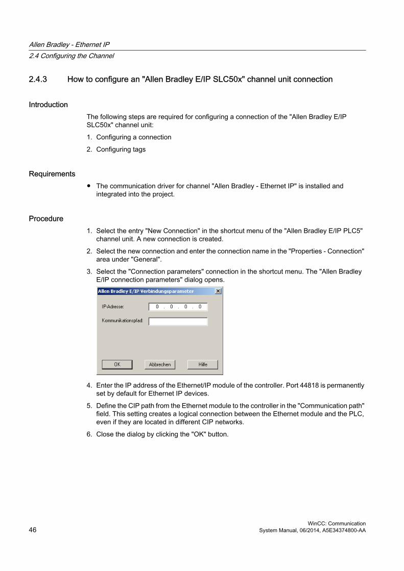
2.4.3 How to configure an "Allen Bradley E/IP SLC50x" channel unit connection
IntroductionThe following steps are required for configuring a connection of the "Allen Bradley E/IP SLC50x" channel unit:
1. Configuring a connection
2. Configuring tags
Requirements● The communication driver for channel "Allen Bradley - Ethernet IP" is installed and
integrated into the project.
Procedure1. Select the entry "New Connection" in the shortcut menu of the "Allen Bradley E/IP PLC5"
channel unit. A new connection is created.
2. Select the new connection and enter the connection name in the "Properties - Connection" area under "General".
3. Select the "Connection parameters" connection in the shortcut menu. The "Allen Bradley E/IP connection parameters" dialog opens.
4. Enter the IP address of the Ethernet/IP module of the controller. Port 44818 is permanently set by default for Ethernet IP devices.
5. Define the CIP path from the Ethernet module to the controller in the "Communication path" field. This setting creates a logical connection between the Ethernet module and the PLC, even if they are located in different CIP networks.
6. Close the dialog by clicking the "OK" button.
Allen Bradley - Ethernet IP2.4 Configuring the Channel
WinCC: Communication46 System Manual, 06/2014, A5E34374800-AA

2.4.4 How to configure an "Allen Bradley E/IP ControlLogix" channel unit connection
IntroductionThe following steps are required for configuring a connection of the "Allen Bradley E/IP ControlLogix" channel unit:
1. Configuring a connection
2. Configuring tags
Requirements● The communication driver for channel "Allen Bradley - Ethernet IP" is installed and
integrated into the project.
Procedure1. Select the entry "New Connection" in the shortcut menu of the "Allen Bradley E/IP PLC5"
channel unit. A new connection is created.
2. Select the new connection and enter the connection name in the "Properties - Connection" area under "General".
3. Select the "Connection parameters" connection in the shortcut menu. The "Allen Bradley E/IP connection parameters" dialog opens.
4. Enter the IP address of the Ethernet/IP module of the controller. Port 44818 is permanently set by default for Ethernet IP devices.
5. Define the CIP path from the Ethernet module to the controller in the "Communication path" field. This setting creates a logical connection between the Ethernet module and the PLC, even if they are located in different CIP networks.
6. Close the dialog by clicking the "OK" button.
Allen Bradley - Ethernet IP2.4 Configuring the Channel
WinCC: CommunicationSystem Manual, 06/2014, A5E34374800-AA 47

2.4.5 Examples: Communication path
Example 1:Connection with a PLC in the same Allen-Bradley rack.
1,0
Number Meaning1 Stands for a backplane connection.0 Stands for a CPU slot number.
Example 2:Connection with a PLC in remote Allen-Bradley racks. Two Allen-Bradley racks are networked on Ethernet.
1,2,2,190.130.3.101,1,5
Number Meaning1 Backplane connection2 Stands for the CPU slot number of the second Ethernet module.2 Stands for an Ethernet connection.190.130.3.101 IP address of a remote AB rack on the network – in particular the third Ethernet
module1 Backplane connection5 Slot number of the CPU
2.4.6 Configuring the tags
2.4.6.1 Configuring the tags
IntroductionFor a connection between WinCC and the automation system (AS) via channel "Allen Bradley - Ethernet IP", tags of different data types can be created in WinCC. The permitted data types are listed in this section.
Allen Bradley - Ethernet IP2.4 Configuring the Channel
WinCC: Communication48 System Manual, 06/2014, A5E34374800-AA

Tag UpdatingIf the tags are retrieved simultaneously in a picture from a PLC, the "Allen Bradley - Ethernet IP" channel attempts to optimize the update. This can only be accomplished under the following conditions however:
● - the tags are in the same address range.
● - the tags are as close to one another as possible within the address range.
If you do not observe these recommendations, it can lead to noticeable differences in the picture refresh with large amounts of tags. The acquisition cycles may not be maintained under certain circumstances.
The best performance for the connection is achieved if you observe the following rules when configuring the tags:
● Update of maximum 2000 tags simultaneously.
● Combine the tags in the least possible space, best in only one address range.
Permitted data typesThe selection of data types listed below can be used to configure tags.
Basic data types
Data type Bit address spaceBool -SInt 0-7USInt 0-7Int 0-15UInt 0-15DInt 0-31UDInt 0-31Real -String -
Arrays
Address Permitted data typesArray SInt, USInt, Int, UInt, DInt, UDInt, Real
Allen Bradley - Ethernet IP2.4 Configuring the Channel
WinCC: CommunicationSystem Manual, 06/2014, A5E34374800-AA 49

2.4.6.2 Addressing
AddressingA tag is uniquely referenced in WinCC by means of an address in the controller. The address must correspond with the tag name in the PLC. The tag address is defined by a string with a length of up to 128 characters.
Using characters for addressingValid characters for tag addressing:
● Letters (a to z, A to Z)
● Numbers (0 to 9)
● Underscore ( _ )
The tag address consists of tag name and other character strings used to specify the tag in the PLC.
Tag name properties:
● The tag name may begin but not end with an underscore character.
● Strings with successive underscore and space characters are invalid.
● The address may not exceed a length of 128 characters.
Note
The characters reserved for tag addressing may not be used in program/tag names or at any other address instance.
The reserved characters are listed below:
Reserved character Function. Element delimiter: Definition of a program tag, Delimiter for addressing multi-dimensional arrays/ Reserved for bit addressing.[ ] Addressing of array elements or arrays
Allen Bradley - Ethernet IP2.4 Configuring the Channel
WinCC: Communication50 System Manual, 06/2014, A5E34374800-AA

Controller and program tagsThe "Allen-Bradley E/IP ControlLogix" allows addressing of PLC tags (global project tags) and/or program tags (global program tags). Program tags are declared via the program names in the controller and the actual tag names. Controller variables are addressed by their names.
NoteAddressing errors
Addressing errors are generated when the tag name and data type are inconsistent.
The tag name defined in the address field in WinCC must correspond with the tag name in the controller. The data type of tags in WinCC and in the controller must correspond.
Note
You cannot address module-specific Tags, such as data at input and output modules, directly. Use an Alias tag in the controller instead.
Example: Local:3:O.data cannot be addressed in WinCC
If, for Local:3:O in the controller, the alias "MyOut" is defined, you can address with WinCC via MyOut.Data.
2.4.6.3 Addressing syntax
Notation of addressesThe following tables define the possibilities for writing individual addressing.
Table 2-1 Access to arrays, basic data types and structure elements
Data types Type AddressBasic data types PLC tag Tag name
Program tag Programname:tagnameArrays PLC tag Array tag
Program tag Program name: array tagBits PLC tag Tagname/bitnumber
Program tag Programname:tagname/bitnumberStructure elements PLC tag Structure tag. Structure element
Program tag Program name: structure tag. structure element
Note
Bit addressing with the data types Bool, Real and String is not permitted and will cause an addressing fault.
Allen Bradley - Ethernet IP2.4 Configuring the Channel
WinCC: CommunicationSystem Manual, 06/2014, A5E34374800-AA 51

Description of the syntaxSyntax description:
(Programname:)tagname([x(,y)(,z)]){.tagname([x(,y)(,z)])}(/bitnumber)● The "( )" defines an optional, single instance of an expression.
● The "{ }" defines an optional expression with multiple single instances.
The address string length may not exceed 128 characters.
2.4.6.4 Addressing Types
Array elementsElements of one-dimensional, two-dimensional and three-dimensional arrays in the PLC are indexed by setting an index and the corresponding notation in the tag editor. Array addressing starts at element "0", with arrays of all basic types being valid for element addressing. Read/write operations are only carried out at the addressed element, and not for the entire array.
Bits and bit tagsBit access is allowed to all basic data types with the exception of Bool, Real and String. Bit addressing is also allowed at array/structure elements. Data type Bool is defined in WinCC for addressing bits and bit tags in the basic data types.
One-place bit numbers will be address with "/x" or "/0x" (x = bit number). Bit numbers are defined by up to two digits.
Note
With the "Bool" data type in the data types SInt, Int and DInt, after changing the specified bit the complete tag is then written in the PLC again. In the meantime, no check is made as to whether other bits in the tag have since changed. Therefore, the PLC may have only read access to the specified tag.
StructuresUser-defined data types are created by means of structures. These structures group tags of different data types. Structures may consist of basic types, arrays and of other structures. In WinCC, only basic data types are addressed as structure elements and not entire structures.
Structure elementsStructure elements are addressed by means of the name of the structure and of the required structure element. This addressing is separated by point. In addition to basic data types, the
Allen Bradley - Ethernet IP2.4 Configuring the Channel
WinCC: Communication52 System Manual, 06/2014, A5E34374800-AA
structure elements may represent arrays or other structures. Only one-dimensional arrays may be used as a structure element.
Note
The nesting depth of structures is only limited by the maximum length of 128 characters for the address.
2.4.6.5 Examples for Addressing
Example of a table for addressingThe following table shows basic addressing variations for control variables. Other addressing variants are possible by means of combination.
Type Type AddressGeneral PLC tag Tag name
Program tag Program:tagnameArray Access to an element of a 2-
dimensional arrayArraytag[Dim1,Dim2]
Element of a structure array (1-dimensional)
Arraytag[Dim1].structureelement
Bit in element of a basic type array (2-dimensional)
Arraytag[Dim1,Dim2]/Bit
Structure Array in structure Structuretag.arraytagBit in element of an array in a sub-structure
Structuretag.structure2.arraytag [element]/bit
Note
Program tags are addressed by leading the address with the program name derived from the PLC with colon delimiter.
Example: Programname:arraytag[Dim1,Dim2]
Access to array elements
Type AddressPLC tag Arraytag[Dim1]
Arraytag[Dim1,Dim2]Arraytag[Dim1,Dim2,Dim3]
Program tag Programname:arraytag[Dim1]
Allen Bradley - Ethernet IP2.4 Configuring the Channel
WinCC: CommunicationSystem Manual, 06/2014, A5E34374800-AA 53

Type AddressProgramname:arraytag[Dim1,Dim2]Programname:arraytag[Dim1,Dim2,Dim3]
2.4.6.6 How to configure a tag for the Allen Bradley E/IP ControlLogix channel unit
IntroductionThis section shows how you configure a tag for channel unit "Allen Bradley E/IP ControlLogix" in the automation system (AS) address range.
Requirements● The channel "Allen Bradley - Ethernet IP" must be integrated in the project.
● A connection must be created in the "Allen Bradley E/IP ControlLogix" channel unit.
Procedure1. Select the connection for which a tag is to be configured.
2. Click the "Tags" tab below the table area.
3. Click in the top free cell of the "Name" column. Enter the name for the tag.
4. Select the desired data type in the "Data type" field.
5. Open the "Allen Bradley ControlLogix Tag" dialog.For this purpose, click in the "Address" field and then on the button.
6. Enter the address of the tags in AS in the "Address" field.
NoteAddressing errors
Addressing errors are generated when the tag name and data type are inconsistent.
The tag name defined in the address field in WinCC must correspond with the tag name in the controller. The data type of tags in WinCC must correspond with the data types in the controller.
7. Close the dialog by clicking the "OK" button.
Allen Bradley - Ethernet IP2.4 Configuring the Channel
WinCC: Communication54 System Manual, 06/2014, A5E34374800-AA

2.4.6.7 How to configure a tag with bit by bit access for Allen Bradley E/IP PLC5 or SLC50x
IntroductionThis section shows you how to configure a tag for bit by bit access for the address area in the automation system (AS).
Requirements● The channel "Allen Bradley - Ethernet IP" must be integrated in the project.
● A connection must be created in the "Allen Bradley E/IP PLC5" or "Allen Bradley E/IP SLC50x" channel unit.
Procedure1. Select the connection for which a tag is to be configured.
2. Click the "Tags" tab below the table area.
3. Click in the top free cell of the "Name" column.Enter the name for the tag.
4. Select the desired data type in the "Data type" field.
5. Open the "Allen Bradley PLC/SLC Tag" dialog.For this purpose, click in the "Address" field and then on the button.
6. Select an address range in the "File" field. Entries N, R, C, T, B, S, I, O, D, A, ST are available.
7. Enter the "File Number" if it is different from the suggested file number.
8. Enter the "Element".
9. Depending on the setting in the "File" field, define the "Bit" to address or select a value for "Bit (octal)" or "Sub".
10.Close the dialog by clicking the "OK" button.
Allen Bradley - Ethernet IP2.4 Configuring the Channel
WinCC: CommunicationSystem Manual, 06/2014, A5E34374800-AA 55

2.4.6.8 How to configure a tag with byte by byte access for Allen Bradley E/IP PLC5 or SLC50x
IntroductionThis section shows you how to configure a tag for byte by byte access for the address area in the automation system (AS).
Requirements● The channel "Allen Bradley - Ethernet IP" must be integrated in the project.
● A connection must be created in the "Allen Bradley E/IP PLC5" or "Allen Bradley E/IP SLC50x" channel unit.
Procedure1. Select the connection for which a tag is to be configured.
2. Click the "Tags" tab below the table area.
3. Click in the top free cell of the "Name" column.Enter the name for the tag.
4. Select the desired data type in the "Data type" field.
5. Open the "Allen Bradley PLC/SLC Tag" dialog.For this purpose, click in the "Address" field and then on the button.
6. Select the A or ST address range in the "File" field.
7. Enter the "File Number" if it is different from the suggested file number.
8. Enter the "Element".
9. Close the dialog by clicking the "OK" button.
2.4.6.9 How to configure a tag with word by word access for Allen Bradley E/IP PLC5 or SLC50x
IntroductionThis section shows you how to configure a tag for word by word access to the address area in the automation system (AS).
Allen Bradley - Ethernet IP2.4 Configuring the Channel
WinCC: Communication56 System Manual, 06/2014, A5E34374800-AA

Requirements● The channel "Allen Bradley - Ethernet IP" must be integrated in the project.
● A connection must be created in the "Allen Bradley E/IP PLC5" or "Allen Bradley E/IP SLC50x" channel unit.
Procedure1. Select the connection for which a tag is to be configured.
2. Click the "Tags" tab below the table area.
3. Click in the top free cell of the "Name" column.Enter the name for the tag.
4. Select the desired data type in the "Data type" field.
5. Open the "Allen Bradley PLC/SLC Tag" dialog.For this purpose, click in the "Address" field and then on the button.
6. Select the address range in the "File" field. Entries N, R, C, T, B, S, I, O, D, A and ST are available.
7. Enter the "File Number" if it is different from the suggested file number. The File number cannot be changed for the setting "S".
8. Enter the "Element".
9. Select one of the values for the "Sub" field if it is displayed. This depends on the setting made in the "File field.
10.Close the dialog by clicking the "OK" button.
2.4.6.10 How to configure a text tag for Allen Bradley E/IP PLC5 or SLC50x
IntroductionThis section shows you how to configure a tag for word by word access to the address area in the automation system (AS).
Allen Bradley - Ethernet IP2.4 Configuring the Channel
WinCC: CommunicationSystem Manual, 06/2014, A5E34374800-AA 57

Requirements● The channel "Allen Bradley - Ethernet IP" must be integrated in the project.
● A connection must be created in the "Allen Bradley E/IP PLC5" or "Allen Bradley E/IP SLC50x" channel unit.
Procedure1. Select the connection for which a tag is to be configured.
2. Click the "Tags" tab below the table area.
3. Click in the top free cell of the "Name" column.Enter the name for the tag.
4. Select the desired data type in the "Data type" field.
5. Open the "Allen Bradley PLC/SLC Tag" dialog.For this purpose, click in the "Address" field and then on the button.
6. Select the A or ST address range in the "File" field.
7. Enter the "File Number" if it is different from the suggested file number. The File number cannot be changed for the setting "S".
8. Enter the "Element".
9. Select one of the values for the "Sub" field if it is displayed. This depends on the setting made in the "File field.
10.Close the dialog by clicking the "OK" button.
Allen Bradley - Ethernet IP2.4 Configuring the Channel
WinCC: Communication58 System Manual, 06/2014, A5E34374800-AA

Mitsubishi Ethernet 33.1 WinCC channel "Mitsubishi Ethernet"
Introduction The "Mitsubishi Ethernet" channel is intended for communication between a WinCC station and Mitsubishi controllers of the FX3U and Q series. The communication takes place via the MELSEC communication protocol (MC protocol).
Channel unitsThe "Mitsubishi Ethernet" channel comes equipped with the "Mitsubishi FX3U Series" and "Mitsubishi Q Series" channel units.
WinCC: CommunicationSystem Manual, 06/2014, A5E34374800-AA 59

3.2 Supported data types
IntroductionDefine the required tags for a logical connection between WinCC and a connected controller.
The following data types are supported by the "Mitsubishi Ethernet" channel:
● Binary Tag
● Signed 16-bit value
● Unsigned 16-bit value
● Signed 32-bit value
● Unsigned 32-bit value
● Floating-point number 32-bit IEEE 754
● Floating-point number 64-bit IEEE 754
● Text tag 8-bit character set
● Text tag 16-bit character set
● Raw Data Tag
Mitsubishi Ethernet3.2 Supported data types
WinCC: Communication60 System Manual, 06/2014, A5E34374800-AA

3.3 Configuring the Channel
3.3.1 Configuring the "Mitsubishi Ethernet" channel
Introduction WinCC needs a logical connection for communication of WinCC with the automation system (AS). This section illustrates how to configure the "Mitsubishi Ethernet" channel.
You can establish a connection to an AS with either TCP/IP or UDP/IP protocol. Therefore, you have to enter the IP address and IP port number for the AS when configuring a logical connection for the channel "Mitsubishi Ethernet" and select either the UDP or TCP/IP protocol. The IP address consists of four numerical values, separated by dots. The numerical values must be within the range 0 to 255.
NoteTimeout Behavior
Interrupted connections are not detected immediately when using the TCP/IP protocol. The feedback can take longer and is dependent on the operating system.
Mitsubishi controllers that are supportedYou can configure logical connections for the following Mitsubishi controllers:
● MELSEC FX3U series
● MELSEC System Q
When you configure the connections and tags, the procedure is identical for both controller families. The configuration differs only in relation to the used address type of the specific controller family. In addition, the routing of information is only supported by MELSEC System Q models.
Online ConfigurationThe "Mitsubishi Ethernet channel supports the online configuration of tags and connections.
3.3.2 How to configure a "Mitsubishi FX3U Series" channel unit connection
Introduction The following steps are required for configuring the "Mitsubishi Ethernet" channel:
1. Configuring a connection
2. Configuring tags
Mitsubishi Ethernet3.3 Configuring the Channel
WinCC: CommunicationSystem Manual, 06/2014, A5E34374800-AA 61

This section shows you how to configure the connection for the "Mitsubishi FX3U Series" channel unit.
Requirements● The communication driver for the "Mitsubishi Ethernet" channel is installed and integrated
into the project.
Note
When you use Mitsubishi controllers, you will also have to configure the connections in the controller. To do this, follow the operating instructions provided by the manufacturer.
Procedure1. In the navigation area of the tag management, select the channel unit "Mitsubishi FX3U
Series" in the tree of the "Mitsubishi Ethernet" communication driver.
2. Select the entry "New Connection" in the shortcut menu of the channel unit.
3. Enter the name of the connection.
4. Select the entry "Connection parameters" from the shortcut menu of the connection.The "Connection properties" dialog opens.
5. Enter the IP address of the controller.
6. Enter the port you want to use for the TCP/IP connection.The valid range of values is from 0 to 65535.
7. Select the protocol to be used, "TCP" or "UDP".
Note
We recommend that you use the default protocol "UDP". The timeout behavior is better with this protocol. Only use TCP if you are not able to use UDP.
Mitsubishi Ethernet3.3 Configuring the Channel
WinCC: Communication62 System Manual, 06/2014, A5E34374800-AA

8. Enter the PC number.If you do not want to enter a PC number, you must enter the value 255 or 0.
9. To establish the connection, select "Establish connection".
10.In each case, close the dialog with "OK".
3.3.3 How to configure a "Mitsubishi Q Series" channel unit connection
Introduction The following steps are required for configuring the "Mitsubishi Ethernet" channel:
1. Configuring a connection.
2. Configuring tags.
This section shows you how to configure the connection for the "Mitsubishi Q Series" channel unit.
Requirements● The communication driver for the "Mitsubishi Ethernet" channel is installed and integrated
into the project.
Note
When you use Mitsubishi controllers, you will also have to configure the connections in the controller. To do this, follow the operating instructions provided by the manufacturer.
Procedure1. In the navigation area of the tag management, select the channel unit "Mitsubishi Q Series"
in the tree of the communication driver "Mitsubishi Ethernet".
2. Select the entry "New Connection" in the shortcut menu of the channel unit.
3. Enter the name of the connection.
Mitsubishi Ethernet3.3 Configuring the Channel
WinCC: CommunicationSystem Manual, 06/2014, A5E34374800-AA 63

4. Select the entry "Connection parameters" from the shortcut menu of the connection.The "Connection properties" dialog opens.
5. Enter the IP address of the controller.
6. Enter the port you want to use for the TCP/IP connection.The valid range of values is from 0 to 65535.
7. Select the protocol to be used, "TCP" or "UDP".
Note
We recommend that you use the default protocol "UDP". The timeout behavior is better with this protocol. Only use TCP if you are not able to use UDP.
8. Enter the network number.The default setting is 0.
9. Enter the PC number.If you do not want to enter a PC number, you must enter the value 255 or 0.
10.To establish the connection, select "Establish connection".
11.Close each dialog box by clicking "OK."
3.3.4 Configuring the tags
3.3.4.1 Configuring the tags
Introduction Tags of different data types can be created in WinCC for a connection between WinCC and the automation system via the "Mitsubishi Ethernet" channel.
The following sections describe how to configure the tags.
Mitsubishi Ethernet3.3 Configuring the Channel
WinCC: Communication64 System Manual, 06/2014, A5E34374800-AA

Address types, address ranges and data typesThe table lists the address types, address ranges and data types that can be used when configuring tags and structured tags. In addition, it is also specified which automation system (AS) the respective address type supports. "FX" here stands for the MELSEC FX3 U series and "Q" for the MELSEC Q system.
Note
If you want to use a specific WinCC data type, you have to consider the selected address type; for example, address type "D" does not support the WinCC data type "Binary".
Address type Code Address range Display Data type AS that are supported
Input relays X 000000...001FFF Hex. (FX:Octal) Bit FX, QOutput relays Y 000000...001FFF Hex. (FX: Octal) Bit FX, QBit memories M 0...8191 Decimal Bit FX, QLatch relay L 0...8191 Decimal Bit QError bit memory F 0...2047 Decimal Bit QEdge relay V 0...2047 Decimal Bit QLink relay B 000000...001FFF Hex. Bit QData register D 0...12287 Decimal Word FX, QLink register W 000000...001FFF Hex. Word QTimer (contact) TS 0...2047 Decimal Bit FX, QTimer (OUT coil) TC 0...2047 Decimal Bit QTimer (current value) TN 0...2047 Decimal Word FX, QRetentive timer (contact)
SS 0...2047 Decimal Bit Q
Retentive timer (coil) SC 0...2047 Decimal Bit QRetentive timer (value) SN 0...2047 Decimal Word QCounter / Contact CS 0...1023 Decimal Bit FX, QCounter / Coil CC 0...1023 Decimal Bit QCounter / current value CN 0...1023 Decimal Word FX, QExpansion register R 0...65535 Decimal 16-bit FX, QSpecial link relay SB 000000...0007FF Hex. Bit QSpecial link register SW 000000...0007FF Hex. Word QStep flags S 0...8191 Decimal Bit QInput relay (direct) DX 000000...001FFF Hex. Bit QOutput relay (direct) DY 000000...001FFF Hex. Bit QIndex register Z 0...15 Decimal Word QDiagnostic bit memory SM 0...2047 Decimal Bit QDiagnostic register SD 0...2047 Decimal Word Q
Mitsubishi Ethernet3.3 Configuring the Channel
WinCC: CommunicationSystem Manual, 06/2014, A5E34374800-AA 65

3.3.4.2 How to configure a tag
Introduction This section shows you how to configure a tag access for the address range in the automation system (AS).
Requirements● The "Mitsubishi Ethernet" channel is integrated in the project.
● A connection is established in the "Mitsubishi FX3U Series" or "Mitsubishi Q Series" channel unit.
Procedure1. Select the connection for which a tag is to be configured.
2. Click the "Tags" tab below the table area.
3. Click in the top free cell of the "Name" column.Enter the name for the tag.
4. Select the desired data type in the "Data type" field.
5. Open the "Address properties" dialog.For this purpose, click in the "Address" field and then on the button.
6. Set the address type.
7. Enter the corresponding data element. The value depends on the configuration of the controller.
Mitsubishi Ethernet3.3 Configuring the Channel
WinCC: Communication66 System Manual, 06/2014, A5E34374800-AA

8. If necessary, enter the raw data length.
9. Close the "Address properties" dialog by clicking "OK".The address of the tag is displayed in the "Address" field of the "Tag properties" dialog. The address is adjusted to the data format of the AS.
Mitsubishi Ethernet3.3 Configuring the Channel
WinCC: CommunicationSystem Manual, 06/2014, A5E34374800-AA 67


Modbus TCPIP 44.1 "Modbus TCP/IP" channel
IntroductionThe "Modbus TCPIP" channel is for communication between a WinCC station and PLCs that support Modbus via Ethernet. The communication is handled with the Modbus TCP/IP protocol.
Channel unitsThe "Modbus TCPIP" channel comes with the "Modbus TCP/IP Unit #1" channel unit.
WinCC: CommunicationSystem Manual, 06/2014, A5E34374800-AA 69

4.2 Supported Data Types
IntroductionDefine the required tags for a logical connection with a connected controller. The following data types are supported by the "Modbus TCPIP" channel:
● Binary tag
● Signed 16-bit value
● Unsigned 16-bit value
● Signed 32-bit value
● Unsigned 32-bit value
● Floating-point number 32-bit IEEE 754
● Text tag 8-bit character set
● Text tag 16-bit character set
Modbus TCPIP4.2 Supported Data Types
WinCC: Communication70 System Manual, 06/2014, A5E34374800-AA

4.3 Configuring the Channel
4.3.1 Configuring the "Modbus TCPIP" Channel
IntroductionWinCC needs a logical connection for communication of WinCC with the automation system (AS). This section describes the communication with the "Modbus TCP/IP Unit #1" channel unit. All connection-specific parameters are defined during the setup.
When implementing the TCP/IP protocol, you must define the IP address of the AS for the logic connection. The IP address consists of four numerical values, separated by dots. The numerical values must be within the range of 0-255.
NoteTimeout Behavior
Interrupted connections are not detected immediately when using the TCP/IP protocol. The check-back message can take up to a minute.
Enabled Communication Methods with Modbus TCPIPThe following types of communication have been system-tested and approved:
● Point-to-point communication
● Multiple point connection of the WinCC station with an optional amount of controllers.
Note
Integrating the WinCC station via a bridge in a Modbus network is not possible because the WinCC station works as a Modbus Master.
Online ConfigurationThe Online configuration is not supported.
4.3.2 How to configure a connection
IntroductionThe following steps are required for configuring the channel "Modbus TCPIP":
1. Configuring a connection
2. Configuring tags
Modbus TCPIP4.3 Configuring the Channel
WinCC: CommunicationSystem Manual, 06/2014, A5E34374800-AA 71

Requirements● The communication driver for channel "Modbus TCPIP" is installed and integrated into the
project.
Procedure1. In the navigation area of the tag management, select the channel unit "Modbus TCPIP
Unit#1" in the tree of the "Modbus TCP/IP" communication driver.
2. Select the entry "New Connection" in the shortcut menu of the channel unit.
3. Enter the name of the connection.
4. Select the entry "Connection parameters" from the shortcut menu of the connection.The "Modbus TCPIP properties" dialog opens.
5. Select the connected Modicon controller under "CPU Type". The following CPUs are available for selection:
– 984Use this CPU type for the CPU 984 (except for CPU 984A, 984B and 984X).
– Modicon Compact, Modicon Quantum, Modicon Momentum
– Modicon Premium, Modicon Micro
6. Enter the IP address of the controller in the "Server" field.
7. Enter the port to be used for the TCP/IP connection in the "Port" field. The default port for Modbus TCP/IP connections is 502.
8. If you are using a bridge, enter the slave address of the remote controller in the "Address of remote slave" field.If no bridge is used, you must enter the default value 255 or 0 as the address.
Note
Integrating the WinCC station via a bridge in a Modbus network is not possible because the WinCC station works as a Modbus Master.
Modbus TCPIP4.3 Configuring the Channel
WinCC: Communication72 System Manual, 06/2014, A5E34374800-AA

9. To swap the order of the 16-bit register in 32-bit process values, select "Swap words in 32-bit values".
10.Close the dialog by clicking "OK".
4.3.3 Configuring the tags
4.3.3.1 Configuring the tags
IntroductionFor a connection between WinCC and the automation system (AS) via channel "Modbus TCPIP", tags of different data types can be created in WinCC.
The following sections describe how to configure the tags. The addressing of the data range in the AS and the data type of the WinCC tags are different.
Tag Updating with the Modbus TCP/IP protocolIf the tags are retrieved simultaneously in a picture from a controller, the Modbus TCP/IP channel attempts to optimize the update. This can only be accomplished under the following conditions however:
● The tags are in the same address range.
● The tags are as close to one another as possible within the address range.
If you do not observe these recommendations, it can lead to noticeable differences in the picture refresh with large amounts of tags. The acquisition cycles may not be maintained under certain circumstances.
The best performance for the connection is achieved if you observe the following rules when configuring the tags:
● Update of maximum 2000 tags simultaneously.
● Combine the tags in the least possible space, best in only one address range.
Data Types and Address Ranges in the Controller The table lists the data types and address ranges that can be used when configuring tags and structured tags.
NameArea with CPU Premium/Micro
Area with CPU 984, Compact, Quantum, Momentum
data type
Coil(discrete output)
%M 1) 0x Bit
Discrete input (%I) – not realized by Premium/Micro
1x Bit
Modbus TCPIP4.3 Configuring the Channel
WinCC: CommunicationSystem Manual, 06/2014, A5E34374800-AA 73

NameArea with CPU Premium/Micro
Area with CPU 984, Compact, Quantum, Momentum
data type
Input register (%IW) – not realized by Premium/Micro
3x Bit,+/- Int, Int
Holding register(output)
%MW 4x Bit 2),+/- Int, Int,+/- Double, Double,Float, ASCII
Extended memory(Only available with the "Quantum/Momentum" CPU)
-- 6x Bit 2),+/- Int, Int,+/- Double, Double,Float, ASCII
1) Due to a system characteristics of the external controller the last x bits on the end of the address area cannot be accessed.2) In the case of write accesses note:
With the "bit" data type in the "4x", "6x" and "%MW" areas, after changing the specified bit the entire word is written back to the controller. There is no check to determine whether any other bits in the word have changed. As a result, the controller only has read access to the specified word.
The standard bit counting method (16 LSB - 1 MSB) used with controllers of the 984, Compact, Quantum and Momentum series will only be used for these CPUs in the "Tags" editor for the data type "bit". Bit positions have the following allocations:
Left byte Right byteCounting with tags 1 2 3 4 5 6 7 8 9 10 11 12 13 14 15 16
When entering bit numbers in other locations in WinCC, the bit allocation of WinCC applies (0 LSB - 15 MSB):
How the bit positions are counted
Left byte Right byte
In the WinCC you configure: 15 14 13 12 11 10 9 8 7 6 5 4 3 2 1 0
This bit counting method also applies to Modicon Premium and Modicon Micro controllers
Format for "Signed"The placeholder "+/-" stands for the data types "Signed Int" and "Signed Double".
See alsoHow to Configure a Tag with Bit by Bit Access (Page 75)
How to Configure a Tag with Word by Word Access (Page 76)
How to Configure a Text Tag (Page 77)
Modbus TCPIP4.3 Configuring the Channel
WinCC: Communication74 System Manual, 06/2014, A5E34374800-AA

4.3.3.2 How to Configure a Tag with Bit by Bit Access
IntroductionThis section shows you how to configure a tag for bit by bit access for the address area in the automation system (AS).
Requirements● The channel "Modbus TCPIP" must be integrated in the project.
● A connection must be created in the "Modbus TCP/IP Unit #1" channel unit.
Procedure1. Select the connection for which a tag is to be configured.
2. Click the "Tags" tab below the table area.
3. Click in the top free cell of the "Name" column.Enter the name for the tag.
4. Set the "Binary tag" data type in the "Data Type" field.
5. Open the "Modbus TCP/IP Tag Properties" dialog.For this purpose, click in the "Address" field and then on the button.
6. Enter the address of the tags in the respective address field, "4x" for instance. The value depends on the configuration of the controller.
7. Enter the address of the bit in the "Bit" field if necessary. Whether an entry is possible depends on your selection in the "Area from" field.
8. Select a value for "File" if you have set the value "6x Extended Memory" in the "Area" field.
9. Close the dialog by clicking "OK".
Note
After closing the "Modbus TCP/IP Tag Properties" dialog, the internal address of the tags in the controller is shown in field "Address" of the "Tag Properties" dialog. This address can differ from the entered address because it is adapted to the AS data format.
Modbus TCPIP4.3 Configuring the Channel
WinCC: CommunicationSystem Manual, 06/2014, A5E34374800-AA 75

See alsoHow to Configure a Text Tag (Page 77)
4.3.3.3 How to Configure a Tag with Word by Word Access
IntroductionThis section shows you how to configure a tag for word by word access to the address area in the automation system (AS).
Requirements● The channel "Modbus TCPIP" must be integrated in the project.
● A connection must be created in the "Modbus TCP/IP Unit #1" channel unit.
Procedure1. Select the connection for which a tag is to be configured.
2. Click the "Tags" tab below the table area.
3. Click in the top free cell of the "Name" column.Enter the name for the tag.
4. Set the data type to "Unsigned 16-bit value" in the "Data Type" field.
5. Open the "Modbus TCP/IP tag properties" dialog.For this purpose, click in the "Address" field and then on the button.
6. Enter the address of the tags in the respective address field, "4x" for instance. The value depends on the configuration of the controller.
7. Close both of the dialogs by clicking the "OK" button.
Note
After closing the "Modbus TCP/IP Tag Properties" dialog, the internal address of the tags in the controller is shown in field "Address" of the "Tag Properties" dialog. This address can differ from the entered address because it is adapted to the AS data format.
Modbus TCPIP4.3 Configuring the Channel
WinCC: Communication76 System Manual, 06/2014, A5E34374800-AA

4.3.3.4 How to Configure a Text Tag
IntroductionThis section shows you how to configure a tag for word by word access to the address area in the automation system (AS).
Requirements● The channel "Modbus TCPIP" must be integrated in the project.
● A connection must be created in the "Modbus TCP/IP Unit #1" channel unit.
Procedure1. Select the connection for which a tag is to be configured.
2. Click the "Tags" tab below the table area.
3. Click in the top free cell of the "Name" column.Enter the name for the tag.
4. In the "Data Type" field, set "Text tag 8-bit character set" as the data type.
5. Open the "Modbus TCP/IP tag properties" dialog.For this purpose, click in the "Address" field and then on the button.
6. Enter the address of the tags in address field "4x". The value depends on the configuration of the controller.
7. Close both of the dialogs by clicking the "OK" button.
Modbus TCPIP4.3 Configuring the Channel
WinCC: CommunicationSystem Manual, 06/2014, A5E34374800-AA 77


OPC Channel 55.1 WinCC OPC Channel
Introduction WinCC can be used as both an OPC server and as an OPC client. The OPC channel is the OPC client application of WinCC.
The OPC communication driver can be used as OPC DA client, OPC XML client, and OPC UA client.
The following OPC components are installed automatically:
● OPC communication driver
● OPC Item Manager
Possible Applications
WinCC as an OPC DA clientIf WinCC is used as an OPC DA client, the OPC channel must be added to the WinCC project. A connection for data exchange is created in the WinCC project of the WinCC OPC DA client; this is used to handle access to the WinCC tags of the OPC DA server.
To simplify the process, the OPC Item Manager is used. A WinCC OPC DA client can access multiple OPC DA servers. This requires that a connection be created for each OPC server. In this way, the WinCC OPC DA client can be used as a central operation and monitoring station.
WinCC: CommunicationSystem Manual, 06/2014, A5E34374800-AA 79

Note
The WinCC OPC channel establishes connections only to OPC servers which have the status "OPC_STATUS_RUNNING".
Note"OPC" channel
Unicode is not supported for connection names. Make sure that you name all connections in the project in the same language. Open the Control Panel of your computer to set the code page of this language for use in programs that do not support Unicode.
OPC Channel5.1 WinCC OPC Channel
WinCC: Communication80 System Manual, 06/2014, A5E34374800-AA

5.2 OPC Item Manager
Introduction A connection and a WinCC tag are configured in the WinCC project of the WinCC OPC client to enable access to tags of an OPC server. The OPC Item Manager simplifies this process for you. The OPC Item Manager is automatically installed with WinCC.
Note"OPC" channel
Unicode is not supported for connection names. Make sure that you name all connections in the project in the same language. Open the Control Panel of your computer to set the code page of this language for use in programs that do not support Unicode.
RequirementsThe following requirements must be met in order to use the OPC Item Manager for configuration:
● The OPC server is an OPC DA server, an OPC XML server, or an OPC UA server
● A tag is already configured on the OPC server.
● If WinCC is to be used as the OPC server the WinCC project of the WinCC OPC server must be enabled. If this is not the case, the OPC Item Manager cannot access the WinCC OPC server.
● It must be possible to access the computer of the OPC servers via the IP address or HTTP.
● The OPC server must support the browser functionality. If that is not the case, access to the tag of the OPC server must be configured manually.
Note
If you change language in the WinCC Explorer while the OPC Item Manager is open, no tags are displayed when you click the "Browse Server" button. Exit the OPC Item Manager before changing language.
Tasks of the OPC Item ManagerThe OPC Item Manager assumes the following tasks:
● Select OPC server
● Creating a connection
● Tag selection
● Adding a tag
OPC Channel5.2 OPC Item Manager
WinCC: CommunicationSystem Manual, 06/2014, A5E34374800-AA 81

Selecting the OPC server
OPC DA serverThe OPC Item Manager can be used to determine the name of the OPC DA server in the network. These OPC DA servers can run on the same computer or on different computers in the connected network environment. For further details, refer to "WinCC OPC DA client ".
OPC XML ServerThe OPC Item Manager cannot be used to determine the name the OPC XML server. The OPC XML server can be added using the "OPC Web Server" button. For further details, refer to "WinCC OPC XML client ".
OPC UA ServerThe OPC Item Manager cannot be used to determine the name the OPC UA server. The OPC UA server can be added using the "OPC UA Server" button. For further details, refer to "WinCC OPC UA client ".
Icons of theOPC Item Manager
Description
A networked computer has not yet been searched for installed OPC DA servers.
The computer was not found in the network or the computer could not be accessed.
A networked computer has been searched for installed OPC DA servers.
A networked computer contains the OPC DA server designated with the OPC symbol. The number indicates which OPC DA specification of the WinCC OPC DA client is used.
\\<LOCAL> Refers to the computer running the OPC Item Manager.
OPC Channel5.2 OPC Item Manager
WinCC: Communication82 System Manual, 06/2014, A5E34374800-AA

Icons of theOPC Item Manager
Description
http://
Name of the OPC XML server. The OPC XML server can be added using the "OPC Web Server" button.
opc.tcp://
Name of the OPC UA server. The OPC UA server can be added using the "OPC UA Server" button.
Creating a connectionThe OPC Item Manager configures all required settings when creating a connection. If a connection to the OPC server has already been created, this function is not available.
Tag selectionYou may use the tag selection dialog to select one or more tags on the OPC server which the WinCC OPC client is to access. Filter criteria can be used to limit the choices in the tag selection dialog.
Adding a tag
The names of the WinCC tags that access the tags of the OPC server can be set in the "Add Tags" dialog.
OPC Channel5.2 OPC Item Manager
WinCC: CommunicationSystem Manual, 06/2014, A5E34374800-AA 83

The WinCC tag name consists of the "prefix", "name" and "suffix". The "Name" field is preconfigured with the "ExampleTag" text. "ExampleTag" stands for the WinCC tag name of the WinCC OPC server.
You can assign a prefix or suffix to distinguish the WinCC tag name on the WinCC OPC client from the WinCC tag name on the WinCC OPC server. When configuring project monitoring, a prefix or suffix must be assigned.
The tag name may be assigned only once in a given WinCC project.
Example
The WinCC tag name on the WinCC OPC DA server is called "OPC_Server_Tag". The "Client_" value is entered in the prefix field and "_xyz" in the suffix field. In the WinCC project of the WinCC OPC DA client, the WinCC tag "Client_OPC_Server_Tag_xyz" is created.
If the tag name on the OPC server contains special characters, they are replaced by an underscore ( "_" ), because not all special characters occurring in tag names are supported by the OPC Item Manager.
Click "Finish" to add the WinCC tags to the WinCC project of the WinCC OPC DA client. The OPC Item Manager automatically sets the data type, the name and the address parameters for the WinCC tag.
See alsoHow to Access a WinCC Tag with the OPC Item Manager (Page 104)
How to Access a WinCC Tag with the OPC Item Manager (Page 87)
OPC Channel5.2 OPC Item Manager
WinCC: Communication84 System Manual, 06/2014, A5E34374800-AA

5.3 Overview of the Supported WinCC Data Types
The list below shows the data types that are supported by the WinCC OPC DA client and WinCC OPC DA server:
● Binary tags
● Signed 8-bit value
● Unsigned 8-bit value
● Signed 16-bit value
● Unsigned 16-bit value
● Signed 32-bit value
● Unsigned 32-bit value
● Floating-point number 32-bit IEEE 754
● Floating-point number 64-bit IEEE 754
● Text tag, 8-bit character set
● Text tag, 16-bit character set
● Raw data type
● Structure types
● Text reference
Note
For structure types, only the structure elements are supported, not the structure itself. However, the structure can be configured later. For more information, refer to the topic "Using structures on the WinCC OPC DA client."
If a text tag is created with the OPC Item Manager, it is assigned a length of 160 characters. This length can be changed to any length.
See alsoHow to Use Structures on the WinCC OPC DA Client (Page 95)
OPC Channel5.3 Overview of the Supported WinCC Data Types
WinCC: CommunicationSystem Manual, 06/2014, A5E34374800-AA 85

5.4 WinCC OPC DA Client
5.4.1 Functionality of the WinCC OPC DA Client
Introduction The OPC channel does not require a separate communication module. The OPC channel is an application which employs the OPC software interface to use an OPC DA server to access process data.
If WinCC is to be used as an OPC DA client, the OPC channel must be added to the WinCC project.
If a communication is established to a WinCC OPC DA server, the values of the WinCC tags are exchanged. To do this, a connection is set up in the WinCC project of the WinCC OPC DA client; it is used to handle access to the WinCC OPC DA server.
For the WinCC OPC DA client to access multiple OPC DA servers, a connection for each of the OPC DA servers must be set up in the WinCC project. For more information about troubleshooting channels and tags, refer to "Troubleshooting".
Note
The WinCC OPC channel establishes connections only to OPC servers which have the status "OPC_STATUS_RUNNING".
Note"OPC" channel
Unicode is not supported for connection names. Make sure that you name all connections in the project in the same language. Open the Control Panel of your computer to set the code page of this language for use in programs that do not support Unicode.
Connection MonitoringThree mechanisms are integrated for connection monitoring in the WinCC OPC-DA client. It is thus possible to take the best possible measures in the event of a network error or malfunction of an OPC DA server.
1. If the processing period for a DCOM activation exceeds warning value of 5 seconds, the tag is assigned the value "Addressing Error". If the processing period exceeds the cancellation value of 10 seconds, the connection to the OPC DA server is interrupted. This is displayed in the "Connection Status" dialog of the WinCC Explorers.
The OPC DA specification 3.00 is provided with the "Keep-Alive" feature. If the OPC DA server supports the OPC DA specifications 3.00, this feature is used. The feature causes the OPC DA server to automatically trigger cyclic updating (call OnDataChange) even if the tag values have not changed. If this regular updating is disabled, the WinCC OPC DA client terminates the connection.
OPC Channel5.4 WinCC OPC DA Client
WinCC: Communication86 System Manual, 06/2014, A5E34374800-AA

The same behavior applies in the case of an OPC DA server which supports the OPC DA specifications 2.05a. In order to check the connection to the OPC DA server, the WinCC OPC DA client requests the status cyclically every 10 seconds. If this regular updating is disabled, the WinCC OPC DA client terminates the connection.
Generally, the WinCC OPC DA client terminates the connection to the OPC DA server when the connection is not capable of functioning. The WinCC OPC DA client attempts to re-establish the connection again, automatically, every 10 seconds.
See alsoHow to Use Structures on the WinCC OPC DA Client (Page 95)
Accessing a WinCC Tag without the OPC Item Manager (Page 93)
Configuring Access with the OPC Item Manager (Page 89)
Overview of the Supported WinCC Data Types (Page 85)
OPC Item Manager (Page 81)
Diagnosis of Channels and Tags (Page 463)
OPC specifications and compatibility (Page 125)
Functionality of the WinCC OPC DA Server (Page 134)
5.4.2 How to Access a WinCC Tag with the OPC Item Manager
5.4.2.1 How to Access a WinCC Tag with the OPC Item Manager
IntroductionWhen an OPC connection is made between WinCC and WinCC, data exchange occurs using WinCC tags. The WinCC OPC DA client uses an OPC connection to read the WinCC tag "OPC_Server_Tag" on the WinCC OPC DA server. To simplify the process, the OPC Item Manager is used.
OPC Channel5.4 WinCC OPC DA Client
WinCC: CommunicationSystem Manual, 06/2014, A5E34374800-AA 87

Requirements● Two computers with WinCC projects.
● Both computers must be accessible via their IP addresses.
Configuration StepsThe following configurations are required in the WinCC project of the WinCC OPC DA client:
● Creation of a connection.
● Configuration of the "XMLClient_OPC_Var1_xyz" WinCC tag on the WinCC OPCXML client which accesses the WinCC tag of the WinCC OPC DA server.
See alsoConfiguring Access with the OPC Item Manager (Page 89)
Configuring the OPC Channel on the WinCC OPC DA Client (Page 88)
Configuring Access with the OPC Item Manager (Page 105)
Example of WinCC to WinCC Connection (Page 137)
5.4.2.2 Configuring the OPC Channel on the WinCC OPC DA Client
IntroductionTo use OPC for data exchange, the OPC channel must be set up in the WinCC project.
Procedure1. Click the "Tag Management" icon in the navigation window of the WinCC Explorer on the
WinCC OPC DA client.
2. Select "Add New Driver" from the "Tag Management" shortcut menu. The "Add New Driver" dialog is opened.
3. Select the "OPC.chn" driver and click the "Open" button. The channel is created and the communication driver is displayed in the tag management.
See alsoConfiguring Access with the OPC Item Manager (Page 89)
OPC Channel5.4 WinCC OPC DA Client
WinCC: Communication88 System Manual, 06/2014, A5E34374800-AA

5.4.2.3 Configuring Access with the OPC Item Manager
Introduction This section explains how to use the OPC Item Manager to configure access to the WinCC tag "OPC_Server_Tag" of the WinCC OPC DA server.
Requirements● Configure an internal tag named "OPC_Server_Tag" of the data type "signed 16-bit value"
in the WinCC project of the WinCC OPC DA server.
● Enable the WinCC project of the WinCC OPC DA server.
● Add the "OPC" channel to the WinCC project of the WinCC OPC DA client.
Note"OPC" channel
Unicode is not supported for connection names. Make sure that you name all connections in the project in the same language. Open the Control Panel of your computer to set the code page of this language for use in programs that do not support Unicode.
OPC Channel5.4 WinCC OPC DA Client
WinCC: CommunicationSystem Manual, 06/2014, A5E34374800-AA 89

Procedure1. In the shortcut menu of the channel unit "OPC Groups(OPCHN Unit#1)" on the WinCC
OPC DA client, select "System Parameters". The "OPC Item Manager" opens.
2. Choose the name of the computer to be used as the WinCC OPC DA server from the selection dialog.Select "OPCServer.WinCC" from the list displayed.
3. Click the "Browse Server" button.The "Filter criteria" dialog is opened.
OPC Channel5.4 WinCC OPC DA Client
WinCC: Communication90 System Manual, 06/2014, A5E34374800-AA

4. Click "Next".The "OPCServer.WinCC ..." dialog is opened.
5. Select the WinCC tag "OPC_Server_Tag".Click the "Add Items" button.
6. If a connection to the WinCC OPC DA server already exists, continue with step 6.If a connection has not been created, a message will be displayed.Click on the "Yes" button. The "New Connection" dialog is opened.
OPC Channel5.4 WinCC OPC DA Client
WinCC: CommunicationSystem Manual, 06/2014, A5E34374800-AA 91

7. Enter "OPCServer_WinCC" as the name of the connection. Click "OK".The "Add Tags" dialog opens.
8. Enter the text "Client_" in the prefix field and the text "_xyz" in the suffix field.
9. Select connection "OPCServer_WinCC".Click "Finish".
10.Click the "Back" button in the "OPCServer.WinCC ..." dialog.Click "Exit" to close the OPC Item Manager.
See alsoConfiguring the OPC Channel on the WinCC OPC DA Client (Page 88)
OPC Channel5.4 WinCC OPC DA Client
WinCC: Communication92 System Manual, 06/2014, A5E34374800-AA

5.4.3 Accessing a WinCC Tag without the OPC Item Manager
IntroductionOPC servers that do not support browser functionality require access to be configured manually. Configuration of WinCC tags on the WinCC OPC DA client is shown using an example of a WinCC-WinCC OPC connection.
Note
To access a WinCC tag without the OPC Item Manager, the ItemID must be set manually. When addressing WinCC tags, the symbolic computer name (server prefix) can also be specified. The ItemID has the following syntax: Server prefix::WinCC tag. If the WinCC tag of the local WinCC project is addressed, the server prefix is omitted.
The following configurations are required in the WinCC project of the WinCC OPC DA client:
1. Selection of the "OPC_Var1" WinCC tag to be accessed.
2. Creation of a connection.
3. Configuration of the "Client_OPC_Var1_xyz" WinCC tag that accesses the WinCC tag of the WinCC OPC DA server.
Requirements● Two computers with WinCC projects.
● Both computers must be accessible via their IP addresses.
● Configure an internal tag named "OPC_Var1" with data type "signed 16-bit value" in the WinCC project of the WinCC OPC DA server.
● Enable the WinCC project of the WinCC OPC DA server.
● Add the OPC channel to the WinCC project of the WinCC OPC DA client.
OPC Channel5.4 WinCC OPC DA Client
WinCC: CommunicationSystem Manual, 06/2014, A5E34374800-AA 93

Note"OPC" channel
Unicode is not supported for connection names. Make sure that you name all connections in the project in the same language. Open the Control Panel of your computer to set the code page of this language for use in programs that do not support Unicode.
Procedure1. Select "New Connection" from the shortcut menu of the channel unit "OPC Groups(OPCHN
Unit#1)" on the WinCC OPC DA client. The "Connection Properties" dialog is opened. Enter a name for the connection in the corresponding field.
2. Click the "Properties" button. A dialog with the connection name in its title is displayed.
For connections to WinCC V 6, the entry in the "OPC Server Name" field must be "OPCServer.WinCC".
3. Enter the name of the computer to be used as the OPC DA server in the "Start Server on this Computer" field. Click "Test Server", to check the connection to the WinCC OPC DA server.
4. Select "New Tag" from the shortcut menu of the connection. The "Tag Properties" dialog opens.
5. Enter the name "Client_OPC_Var1_xyz" in the "Tag" field. Set the data type to "signed 16-bit".
OPC Channel5.4 WinCC OPC DA Client
WinCC: Communication94 System Manual, 06/2014, A5E34374800-AA

6. In the "Tag Properties" dialog, click the "Select" button. The "Address Properties" dialog opens.
Enter the name of the WinCC tag of the WinCC OPC DA server in the "Item Name" field. Leave the entry in the "Access Path" field unchanged. Set the data type to "signed 16-bit".
7. Click "OK" to close all open dialogs.
5.4.4 Using Structures on a WinCC OPC DA Client
5.4.4.1 How to Use Structures on the WinCC OPC DA Client
IntroductionStructures are used to organize tags and tag types that form a logical unit. This allows them to be referenced using a single logical name.
Structures are not supported by the OPC DA specification. As a result, structures cannot be set up using the OPC Item Manager, only the individual tags in a structure. If you wish to use structures on the WinCC OPC DA client nonetheless, the data structure must be configured subsequently in the WinCC project of the WinCC OPC DA client in order to supply it with the relevant item names of the server tags.
Requirements● Two computers with WinCC projects.
● Both computers must be accessible via their IP addresses.
Configuration stepsThe following configuration steps are necessary to use structures on the WinCC OPC DA client:
● Configuring structures and structure tags on the WinCC OPC DA server
● Using structures on the WinCC OPC DA client in the WinCC project
OPC Channel5.4 WinCC OPC DA Client
WinCC: CommunicationSystem Manual, 06/2014, A5E34374800-AA 95

See alsoHow to Configure Structures on the WinCC OPC DA Client (Page 97)
Configuring Structures and Structure Tags on the WinCC OPC DA Server (Page 96)
5.4.4.2 Configuring Structures and Structure Tags on the WinCC OPC DA Server
IntroductionIn this section a structure and a structure tag is created in the WinCC project of the OPC DA server. This configuration is required for the OPC DA client to access the structure tag.
Procedure1. Select "New Structure Type" from the structure types shortcut menu on the WinCC OPC
DA server. The "Structure Properties" dialog is displayed.
2. Click "New Element" and create the internal tag "OPCServer_Struct" of data type SHORT.
Click "OK" to close the dialog.
3. In the navigation window, click the plus sign in front of the icon for tag management. Select "New Tag" from the internal tag shortcut menu. Create a WinCC tag named "Var" with this structure type.
4. The data frame of the WinCC Explorer shows the single tag "Var" and the structure tag "Var.OPCServer_Struct".
5. Activate the WinCC project.
OPC Channel5.4 WinCC OPC DA Client
WinCC: Communication96 System Manual, 06/2014, A5E34374800-AA

See alsoHow to Configure Structures on the WinCC OPC DA Client (Page 97)
5.4.4.3 How to Configure Structures on the WinCC OPC DA Client
IntroductionStructures are not supported by the OPC DA specification. As a result, structures cannot be set up using the OPC Item Manager. In this section, the structure already present in the WinCC project of the WinCC OPC DA server is configured for the WinCC project of the WinCC OPC DA client. A WinCC tag that accesses the existing structure tag on the WinCC OPC DA server is configured on the WinCC OPC DA client.
Requirements● Create a structure and a structure tag named "Var.OPCServer_Struct" in the WinCC project
of the WinCC OPC DA server.
● Enable the WinCC project of the WinCC OPC DA server.
● Add the OPC channel to the WinCC project of the WinCC OPC DA client.
Note"OPC" channel
Unicode is not supported for connection names. Make sure that you name all connections in the project in the same language. Open the Control Panel of your computer to set the code page of this language for use in programs that do not support Unicode.
Procedure1. Select "New Structure Type" from the structure types shortcut menu on the WinCC OPC
DA client. The "Structure Properties" dialog is displayed.
2. Click the "New Element" button and set up an external tag. Name the element exactly as it is in the WinCC project of the OPC-DA server. Click "OK" to close the "Structure Properties" dialog.
3. If a connection to the OPC DA server already exists, continue with step 6.If no connection has been created, select "New Connection" from the shortcut menu of the channel unit "OPC". The "Connection Properties" dialog is opened. Enter a name for the connection in the corresponding field.
4. Click the "Properties" button. A dialog with the connection name in its title is displayed. For connections to WinCC V 6, the entry in the field "OPC Server Name" must be "OPCServer.WinCC".
5. Enter the name of the computer to be used as the WinCC OPC DA server in the field "Start Server on this Computer". Click "Test Server", to check the connection to the WinCC OPC DA server. Click "OK" to close the dialog.
OPC Channel5.4 WinCC OPC DA Client
WinCC: CommunicationSystem Manual, 06/2014, A5E34374800-AA 97

6. Select "New Tag" from the shortcut menu of the connection. The "Tag Properties" dialog opens. Select the newly created structure type as the data type.
7. In the "Tag Properties" dialog, click the "Select" button. The "Address properties" dialog opens.In the "Item Name" field, enter the name "Var.OPCServer_Struct" for the structure tag of the WinCC OPC DA server. Leave the entry in the "Access Path" field unchanged.
8. Click "OK" to close all open dialogs.
See alsoConfiguring the OPC Channel on the WinCC OPC DA Client (Page 88)
Configuring Structures and Structure Tags on the WinCC OPC DA Server (Page 96)
5.4.5 Error Handling in the Event of Disturbed OPC DA Communication
5.4.5.1 Error Handling in the Event of Disturbed OPC Communication
IntroductionThe procedure for communication testing is independent of how WinCC is used.
WinCC Used as the OPC DA ServerUse the channel diagnostics on the WinCC OPC DA client to determine whether a connection to the OPC DA server can be established. For more information regarding channel problem analysis, refer to "Troubleshooting".
WinCC Used as the OPC DA ClientUse the channel diagnostics on the WinCC OPC DA client to determine whether a connection to the OPC DA server can be established. For more information regarding channel problem analysis, refer to "Troubleshooting".
See alsoWinCC is used as the OPC DA client, and the connection is not established. (Page 102)
WinCC is used as the OPC DA client, and the connection is established. (Page 101)
WinCC is used as the OPC DA server, and the connection is not established. (Page 100)
WinCC is used as the OPC DA server, and the connection is established successfully. (Page 99)
Possibilities for Diagnosing the "OPC" Channel (Page 498)
OPC Channel5.4 WinCC OPC DA Client
WinCC: Communication98 System Manual, 06/2014, A5E34374800-AA

5.4.5.2 WinCC as OPC DA Server
WinCC is used as the OPC DA server, and the connection is established successfully.
OPC Channel5.4 WinCC OPC DA Client
WinCC: CommunicationSystem Manual, 06/2014, A5E34374800-AA 99

WinCC is used as the OPC DA server, and the connection is not established.
OPC Channel5.4 WinCC OPC DA Client
WinCC: Communication100 System Manual, 06/2014, A5E34374800-AA

5.4.5.3 WinCC as OPC DA Client
WinCC is used as the OPC DA client, and the connection is established.
OPC Channel5.4 WinCC OPC DA Client
WinCC: CommunicationSystem Manual, 06/2014, A5E34374800-AA 101

WinCC is used as the OPC DA client, and the connection is not established.
OPC Channel5.4 WinCC OPC DA Client
WinCC: Communication102 System Manual, 06/2014, A5E34374800-AA

5.5 WinCC OPC XML Client
5.5.1 Functionality of the WinCC OPC XML Client
Introduction The OPC channel does not require a separate communication module. The OPC communication driver can be implemented as the OPC XML client.
In order to use WinCC as the WinCC OPC XML client, the OPC channel must be added to the WinCC project.
The WinCC OPC XML client provides the OPC XML server with the OPC process data as a web page. Access can be made to the web page via the Internet / Intranet using HTTP. When a WinCC OPC XML client requests data, the web service is automatically started by the web server.
In order that the WinCC OPC XML client can access several OPC XML servers, a connection must be made to each OPC XML server in the WinCC project.
If a communication is established to a WinCC OPC XML server, the values of the WinCC tags are exchanged. A connection is set up in the WinCC project of the WinCC OPC XML client via which access to the WinCC OPC XML server can be processed. The connection monitoring is not activated in the case of a WinCC OPC XML client.
NOTICE
Operation with multiple network adapters and activated TCP/IP
For operation with multiple network adapters and activated TCP/IP protocol, observe the information in sections "WinCC Release Notes/Notes on Operation/Network Technology and UPS" and "Configurations/Distributed Systems/System Behavior in Runtime/Special Features of Communication using the Server with Several Network Adapters".
Note
The WinCC OPC channel establishes connections only to OPC servers which have the status "OPC_STATUS_RUNNING".
Note"OPC" channel
Unicode is not supported for connection names. Make sure that you name all connections in the project in the same language. Open the Control Panel of your computer to set the code page of this language for use in programs that do not support Unicode.
OPC Channel5.5 WinCC OPC XML Client
WinCC: CommunicationSystem Manual, 06/2014, A5E34374800-AA 103

See alsoOverview of the Supported WinCC Data Types (Page 85)
OPC Item Manager (Page 81)
OPC specifications and compatibility (Page 125)
Mode of Operation (Page 129)
5.5.2 How to Access a WinCC Tag with the OPC Item Manager
5.5.2.1 How to Access a WinCC Tag with the OPC Item Manager
IntroductionWhen an OPC connection is made between WinCC and WinCC, the data is exchanged by means of WinCC tags. The WinCC OPC DA client uses an OPC connection to read the WinCC tag "OPC_Server_Tag" on the WinCC OPC XML server. To simplify the process, the OPC Item Manager is used.
Requirements● Two computers with WinCC projects.
● It must be possible to access both computers using HTTP.
Configuration StepsThe following configurations are required in the WinCC project of the WinCC OPC XML client:
See alsoConfiguring the OPC Channel on the WinCC OPC DA Client (Page 88)
Configuring Access with the OPC Item Manager (Page 105)
OPC Channel5.5 WinCC OPC XML Client
WinCC: Communication104 System Manual, 06/2014, A5E34374800-AA

5.5.2.2 Configuring Access with the OPC Item Manager
IntroductionThis section explains how to use the OPC Item Manager to configure access to the "OPC_XMLServer_Tag" WinCC tag of the WinCC OPC XML server.
Requirements● Configure an internal tag named "OPC_XMLServer_Tag" of data type "signed 16-bit value"
in the WinCC project of the WinCC OPC XML server.
● Activate the WinCC project of the WinCC OPC XML server.
● The OPC channel must be added to the WinCC project of the WinCC OPC XML client.
Note"OPC" channel
Unicode is not supported for connection names. Make sure that you name all connections in the project in the same language. Open the Control Panel of your computer to set the code page of this language for use in programs that do not support Unicode.
OPC Channel5.5 WinCC OPC XML Client
WinCC: CommunicationSystem Manual, 06/2014, A5E34374800-AA 105

Procedure1. Select "System Parameters" from the shortcut menu of the channel unit "OPC
Groups(OPCHN Unit#1)" on the WinCC OPC XML client. The "OPC Item Manager" opens.
2. Click the "OPC Web Server" button. The "Add OPC Web Server" dialog is opened. Enter the URL of the WinCC OPC XML server in the "URL" field in following format: <http://<xxx>/WinCC-OPC-XML/DAWebservice.asmx>. Replace xxx with either the IP address or the computer name on which the OPC XML web service is running.
Click "OK" to close the dialog.
OPC Channel5.5 WinCC OPC XML Client
WinCC: Communication106 System Manual, 06/2014, A5E34374800-AA

3. A list appears from which to select "/WinCC-OPC-XML/DAWebservice.asmx>". Click the "Browse Server" button. The "Filter criteria" dialog is opened.
4. Click the "Next->" button in the "Filter Criteria" dialog. The "http:// ..." dialog is opened.
5. In the "http:// ..." dialog, select the WinCC tag "XMLOPC_Server_Tag". Click the "Add Items" button.
6. If a connection to the WinCC OPC XML server already exists, continue with step 7. If no connection has been configured, a corresponding message is output.Click "Yes". The "New Connection" dialog is opened.
Enter the name "OPCXMLServer_WinCC" for the connection. Click "OK".
OPC Channel5.5 WinCC OPC XML Client
WinCC: CommunicationSystem Manual, 06/2014, A5E34374800-AA 107

7. The "Add Tags" dialog opens.Enter the string "XMLClient_" in the prefix field, and "_xyz" in the suffix field. Select the "OPCXMLServer_WinCC" connection. Click "Finish".
8. In the "http:// ..." dialog, click "<- Back". Click "Exit" to close the OPC Item Manager.
See alsoConfiguring the OPC Channel on the WinCC OPC DA Client (Page 88)
5.5.3 Accessing a WinCC Tag without the OPC Item Manager
IntroductionOPC servers that do not support browser functionality require access to be configured manually. Configuration of WinCC tags on the WinCC OPC XML client is shown using an example of a WinCC - WinCC OPC connection.
Note
To access a WinCC tag without the OPC Item Manager, the ItemID must be set manually. When addressing WinCC tags, the symbolic computer name (server prefix) can also be specified. The ItemID has the following syntax: server_prefix::<@>WinCC tag. If the WinCC tag of the local WinCC project is addressed, the ItemID has the following syntax: <@>WinCC tag.
OPC Channel5.5 WinCC OPC XML Client
WinCC: Communication108 System Manual, 06/2014, A5E34374800-AA

Configuration StepsThe following configurations are required in the WinCC project of the WinCC OPC XML client:
1. Creation of a connection.
2. Configuring the "XMLClient_OPC_Var1_xyz" WinCC tag on the WinCC OPC XML client which accesses the WinCC tag of the WinCC OPC DA server.
Requirements● Two computers with WinCC projects.
● It must be possible to access the computers using HTTP.
● Configure an internal tag named "XMLOPC_Server_Tag" with data type "signed 16-bit value" in the WinCC project of the WinCC OPC XML server.
● Enable the WinCC project of the WinCC OPC XML server.
● The OPC channel must be added to the WinCC project of the WinCC OPC XML client.
Note
When configuring external tags in the OPC channel, the preset values from WinCC in the type conversion field of the "Tag Properties" dialog must not be altered. The data type of the tag in the process is set in the data type field of the "Address Properties" dialog.
Procedure1. Select "New Connection" from the shortcut menu of the channel unit "OPC Groups(OPCHN
Unit#1)" on the WinCC OPC XML client. The "Connection Properties" dialog is opened. Enter a name for the connection in the corresponding field.
2. Click the "Properties" button. A dialog with the connection name in its title is displayed.
Select the "XML DA Server" check box. In the case of a connection to the WinCC OPC XML server, the "OPC Server Name" field must contain the URL of the WinCC OPC XML server. The URL has the following syntax: "http://<xxx>/WinCC-OPC-XML/DAWebservice.asmx". Replace xxx with either the IP address or the computer name on which the OPC-XML web service is running.
OPC Channel5.5 WinCC OPC XML Client
WinCC: CommunicationSystem Manual, 06/2014, A5E34374800-AA 109

3. Select "New Tag" from the shortcut menu of the connection. The "Tag Properties" dialog is opened.
4. Enter the name "XMLClient_OPC_Var1_xyz" in the "Tag" field. Set the data type to "signed 16-bit".
5. In the "Tag Properties" dialog, click the "Select" button. A dialog with the tag name in its title is displayed.
Enter the symbol "<@>" and the name of the WinCC tag of the WinCC OPC XML server in the "Item Name" field. Leave the entry in the "Access Path" field unchanged. Set the data type to "signed 16-bit".
6. Click "OK" to close all open dialogs.
OPC Channel5.5 WinCC OPC XML Client
WinCC: Communication110 System Manual, 06/2014, A5E34374800-AA

5.6 WinCC OPC UA client
5.6.1 Functionality of the WinCC OPC UA client
Introduction The WinCC OPC UA client enables data access to any OPC UA server in accordance with the OPC Unified Architecture specification. OPC Unified Architecture (OPC UA) also provides additional mechanisms such as authentication and encryption for secure communication between participating partners.
To use WinCC as WinCC OPC UA client, add the OPC communication driver (OPC channel) to the WinCC project. A separate communication module is not required.
To enable access to the OPC process data of different OPC UA servers, configure a connection to each server in the WinCC project. Use the WinCC OPC Item Manager to configure the connections.
Note
Connection monitoring is not activated if the OPC channel is used as OPC UA client.
Connections are only established to servers which signal the status "RUNNING".
5.6.2 Accessing a tag using the OPC Item Manager
5.6.2.1 Accessing an OPC tag using the OPC Item Manager
Introduction If there is an OPC link from WinCC to an OPC UA server, OPC UA server data is mapped to a WinCC tag. In this process, the WinCC OPC UA client uses a secure connection to access the "OPC_UAServer_Tag" of the WinCC OPC UA server. Use OPC Item Manager for your configuration.
Note
You can only access servers that offer browse support during the configuration.
Distinguish between client and server certificates when configuring. Secure communication is only possible when client and server recognize each other's certificates.
Certificates are linked to the respective computers. After having moved, copied, or duplicated the WinCC project to a different computer, repeat this procedure so that each computer can verify the other's certificates.
OPC Channel5.6 WinCC OPC UA client
WinCC: CommunicationSystem Manual, 06/2014, A5E34374800-AA 111

Requirements● Client computers with a WinCC project.
● Both computers must be accessible via TCP connection.
● The Firewall allows two-way communication with the UA server.
Configuration StepsComplete the following configuration tasks in the WinCC project of the WinCC OPC UA client:
● Configuration of the OPC channel on the WinCC OPC UA client.
● Setup of a valid server certificate.
● Configuration of access with the OPC Item Manager.
5.6.2.2 How to set up a server certificate
IntroductionThis section explains how to set up an OPC UA server certificate for the WinCC OPC UA client.
Requirements● The OPC UA server is activated.
● The Firewall allows two-way communication with the UA server.
● The "OPC" channel has been added to the WinCC project of the WinCC OPC UA client.
OPC Channel5.6 WinCC OPC UA client
WinCC: Communication112 System Manual, 06/2014, A5E34374800-AA

Procedure1. On the WinCC OPC UA client, select the "System parameters" command from the shortcut
menu of the "OPC Groups(OPCHN Unit#1)" channel unit. The "OPC Item Manager" opens.
2. Click "OPC UA server". The "Add OPC UA server" dialog opens. Enter the URL of the WinCC OPC UA server in the "Server URL" field in the following format:<opc.tcp://OPC UA server address>Make the required security settings. If necessary, enter authentication data.
Close the dialog with "OK".
3. Select the "<opc.tcp://OPC UA server address>" entry from the list displayed.
4. Click "Browse Server".An error dialog opens.
5. Close the error dialog.
OPC Channel5.6 WinCC OPC UA client
WinCC: CommunicationSystem Manual, 06/2014, A5E34374800-AA 113

6. Open Windows Explorer and change to the "OPC" folder in the WinCC installation path.
7. Open the "PKI/CA/" folder.The "rejected" folder containing the rejected server certificate has been added.
8. Move the server certificate from the "rejected" folder to the "certs" folder.The server certificate has been validated. It is now possible to activate a secure connection to the OPC UA server.
5.6.2.3 How to configure access to a tag using the OPC Item Manager
IntroductionThis section explains how to use OPC Item Manager to configure access to the "OPC_UAServer_Tag" WinCC tag of the WinCC OPC UA server.
Note
You can only access servers that offer browse support during the configuration.
Requirements● The OPC UA server is activated.
● The Firewall allows two-way communication with the UA server.
● The server certificate has been set up.
● The "OPC" channel has been added to the WinCC project of the WinCC OPC UA client.
Note"OPC" channel
Unicode is not supported for connection names. Make sure that you name all connections in the project in the same language. Open the Control Panel of your computer to set the code page of this language for use in programs that do not support Unicode.
OPC Channel5.6 WinCC OPC UA client
WinCC: Communication114 System Manual, 06/2014, A5E34374800-AA

Procedure1. On the WinCC OPC UA client, select "System parameters" from the shortcut menu of the
channel unit "OPC Groups(OPCHN Unit#1)". The "OPC Item Manager" opens.
2. Click "OPC UA server". The "Add OPC UA server" dialog opens. Enter the URL of the WinCC OPC UA server in the "Server URL" field in the following format:<opc.tcp://OPC UA server address>Make the required security settings. If necessary, enter authentication data.
Click "OK" to close the dialog.
OPC Channel5.6 WinCC OPC UA client
WinCC: CommunicationSystem Manual, 06/2014, A5E34374800-AA 115

3. Select the "<opc.tcp://OPC UA server address>" entry from the list displayed. Click "Browse Server". The "Filter criteria" dialog is opened.
4. Click "Next". The "opc.tcp:// ..." dialog opens.
5. Select the tag to be mapped in the "opc.tcp:// ..." dialog, e.g. "OPC_UA_Server_Tag". Click "Add items".
OPC Channel5.6 WinCC OPC UA client
WinCC: Communication116 System Manual, 06/2014, A5E34374800-AA

6. Continue with step 7 if you have already set up a connection to the WinCC OPC UA server. A message will be output if this connection is not available.Click "Yes". The "New Connection" dialog is opened.
Enter the connection name "OPCUAServer". Click "OK".
7. The "Add Tags" dialog opens.Enter the "UAClient_" string in the "Prefix" field and the "xyz" string in the "Suffix" field.Select the "OPCUAServer" connection. Click "Finish".
8. Click "Back" in the "opc.tcp:// ..." dialog.Click "Exit" in the "OPC Item Manager" dialog to close the OPC Item Manager.
OPC Channel5.6 WinCC OPC UA client
WinCC: CommunicationSystem Manual, 06/2014, A5E34374800-AA 117

5.6.3 Error handling in event of disturbed communication
IntroductionThe procedure for communication testing is independent of how WinCC is used.
WinCC used as OPC UA serverFirst, run the channel diagnostics on the WinCC OPC UA client to check whether it is possible to set up a connection to the OPC UA server. For more information regarding channel problem analysis, refer to "Troubleshooting".
WinCC used as OPC UA clientFirst, run the channel diagnostics on the WinCC OPC UA client to check whether it is possible to set up a connection to the OPC UA server. For more information regarding channel problem analysis, refer to "Troubleshooting".
OPC Channel5.6 WinCC OPC UA client
WinCC: Communication118 System Manual, 06/2014, A5E34374800-AA

5.6.3.1 WinCC as OPC UA server
WinCC is used as OPC UA server, and the connection is set up.
OPC Channel5.6 WinCC OPC UA client
WinCC: CommunicationSystem Manual, 06/2014, A5E34374800-AA 119

WinCC is used as the OPC UA server, and the connection is not set up.
OPC Channel5.6 WinCC OPC UA client
WinCC: Communication120 System Manual, 06/2014, A5E34374800-AA

5.6.3.2 WinCC as OPC UA client
WinCC is used as the OPC UA client, and the connection is set up.
OPC Channel5.6 WinCC OPC UA client
WinCC: CommunicationSystem Manual, 06/2014, A5E34374800-AA 121

WinCC is used as OPC UA client, and the connection is not set up.
OPC Channel5.6 WinCC OPC UA client
WinCC: Communication122 System Manual, 06/2014, A5E34374800-AA

OPC - Open Connectivity 66.1 OPC - Open Connectivity
ContentsThe OPC standard software interface allows devices and applications from various manufacturers to be combined with one another in a uniform manner.
WinCC can be used as an OPC server or an OPC client. The "OPC" channel represents the OPC client application of WinCC.
This chapter describes
● the OPC servers of WinCC
● how to use OPC in WinCC
● how to set up various OPC DA links
● how to configure the access to the WinCC message system
● how the WinCC message system appears on the OPC A&E
● how to set up access to the WinCC archive system
WinCC: CommunicationSystem Manual, 06/2014, A5E34374800-AA 123
6.2 Functionality of OPCOPC is a standardized manufacturer-independent software interface for data exchange in automation engineering.
OPC interfaces allow the standard linking of devices and applications from different manufacturers.OPC is based on the Windows COM (Component Object Model) and DCOM (Distributed Component Object Model) technologies.
OPC XML DA provides an additional software interface that is based on the XML, SOAP and HTTP Internet standards.
OPC UA (Unified Architecture) is the successor technology to OPC. OPC UA is platform-independent and supports different protocols as communication medium.
OPC - Open Connectivity6.2 Functionality of OPC
WinCC: Communication124 System Manual, 06/2014, A5E34374800-AA

6.3 OPC specifications and compatibility
OverviewOPC specifies the interfaces for access to the following objects in WinCC:
● Process values (OPC Data Access 2.05a, 3.0; OPC XML Data Access 1.01; OPC UA 1.02)
● Archived process values (OPC Historical Data Access 1.20; OPC UA 1.02)
● Chronological messages (OPC Historical Alarms and Events v1.10
● Messages (OPC Alarms and Events 1.10; OPC UA 1.02)
For more information about individual OPC specifications, refer to the OPC Foundation website.
CompatibilitySupport of these specifications is regularly monitored by the "Compliance Test Tool" (CTT) of the OPC Foundation. Interoperability with OPC products from other manufacturers is guaranteed by participation in "OPC Interoperability Workshops".
The test results submitted are published on the OPC Foundation website. To view the results, enter the search term "OPC Self-Certified Products".
See alsowww.opcfoundation.org (http://www.opcfoundation.org)
OPC - Open Connectivity6.3 OPC specifications and compatibility
WinCC: CommunicationSystem Manual, 06/2014, A5E34374800-AA 125

6.4 Using OPC in WinCC
IntroductionIn WinCC, servers are available for the following OPC interfaces:
● OPC Data Access / OPC XML Data Access: Access to the WinCC body of data
● OPC Historical Data Access: Access to the WinCC archive system
● OPC Alarms&Events: Access to the WinCC message system
● OPC Unified Architecture: Access to the WinCC body of data and archive system
WinCC contains an OPC channel by default. The OPC channel can access the relevant OPC servers as client via OPC DA , OPC XML DA or OPC UA.
WinCC OPC communications conceptData exchange between a WinCC OPC server and OPC client is completed via DCOM. After installation of WinCC, the DCOM settings of the WinCC OPC server are correctly configured.
If a WinCC OPC server or client communicates with an external OPC system, corresponding adaptations must be performed. The "Local access" and "Remote access" authorizations must be entered for the user in "DCOM/Workplace/COM Security/Access rights/Edit default" of User Administration on the client.
The OPC XML server of WinCC is implemented as a web service. This gives you access to your PC via the Internet. You therefore need to define appropriate access rights.
The following shows the WinCC OPC communication concept:
OPC - Open Connectivity6.4 Using OPC in WinCC
WinCC: Communication126 System Manual, 06/2014, A5E34374800-AA

Licensing
OPC server LicensingWinCC OPC DA server A valid RT license for WinCCWinCC OPC XML DA ServerWinCC OPC UA ServerWinCC OPC HDA serverWinCC OPC A&E Server
A valid RT license for WinCCWinCC Option Connectivity Pack
OPC - Open Connectivity6.4 Using OPC in WinCC
WinCC: CommunicationSystem Manual, 06/2014, A5E34374800-AA 127

6.5 How to configure Windows for the use of WinCC OPC
Introduction The OPC client and the OPC server are DCOM applications. A distributed DCOM application can only be run under the same user account. Therefore the OPC server must recognize the OPC client's user account and vice-versa. If the WinCC OPC servers are used with WinCC OPC clients, the correct configuration is already warranted by the installation.
Declaration of the user account, if an external OPC server or client is used For additional information on the granting of user rights, refer to the Windows documentation.
RequirementsLog on as the administrator to both the WinCC OPC server and OPC client workstations to configure the user permissions.
Procedure using Windows 7 as an example1. Go to "Control Panel > System and Security > Administrative Tools > Computer
Management > Local Users and Groups".
2. In the "Users" shortcut menu, select "New User".In the "New User" dialog, enter the user account details of the communication partner. Click "Create" and close the dialog.
3. Click the "Users" icon. Double-click the relevant user. The "Properties" dialog for this user is displayed.
4. Click the "Member Of" tab. Click "Add". The "Select group" dialog is opened.
5. Add the group "Users".If you are on a computer that has WinCC installed, also add the group "SIMATIC HMI". Click "OK" to close all open dialogs.
How to adapt the Windows firewall settingsAfter installation of WinCC, the Windows firewall settings of the WinCC OPC servers are correctly configured.
If OPC clients access OPC servers in different subnets, you must adapt the configuration of the permitted network areas to the OPC servers.
OPC - Open Connectivity6.5 How to configure Windows for the use of WinCC OPC
WinCC: Communication128 System Manual, 06/2014, A5E34374800-AA

6.6 WinCC OPC XML DA Server
6.6.1 Mode of Operation
Introduction The OPC XML DA server from WinCC is realized as a web service of the Microsoft Internet Information Server (IIS).
The WinCC OPC XML DA server provides the OPC XML client with the OPC process data as a web page. The web page can be accessed via the Internet using HTTP. The address of the WinCC OPC XML DA Server is: <http://<xxx>/WinCC-OPC-XML/DAWebservice.asmx>"
The WinCC OPC XML DA server is not visible in WinCC. When an OPC XML client requests data, the Web service is automatically started by the Web server.
To establish successful OPC communication, the following must be observed:
● The WinCC project of the WinCC OPC XML DA server must be activated.
● The computer of the WinCC OPC XML DA server must be capable of being accessed via HTTP.
LicensingIn order to operate the WinCC OPC XML DA server, the following licenses must be installed on each WinCC computer implemented as an OPC XML server:
● A valid RT license for WinCC
● WinCC Option Connectivity Pack
Special features of tags of "String" typeIf you use tags of "string" type that logically stand for floating point values, there can be problems when OPC clients want to write and read.
DescriptionAn OPC client writes to a string tag and does not enter the new value in the form of a string but as float, double or decimal.
ProblemThe comma that indicated the decimal value (in German) can be lost. This will result in a wrong value.
This also affects the read access to string tags if the read value is requested in the float, double or decimal format.
RemedyOnly use the respective floating point tags for the floating point values. Access string tags only in string format.
OPC - Open Connectivity6.6 WinCC OPC XML DA Server
WinCC: CommunicationSystem Manual, 06/2014, A5E34374800-AA 129

See alsoFunctionality of the WinCC OPC XML Client (Page 103)
Overview of the Supported WinCC Data Types (Page 85)
www.opcfoundation.org (http://www.opcfoundation.org)
6.6.2 Installation
IntroductionOPC XML enables access to the process tags via the Internet. In order to operate OPC XML, a number of additional software components must be installed.
Note
It is essential to observe the sequence of installation steps as described here. Otherwise, there might be problems during installation.
Requirement● Installation of the Internet Information Server (IIS)
● Installed Microsoft .NET Framework V4.0 from the WinCC product DVD
● Installation of the WinCC OPC XML Server Using WinCC Setup
Installation of the Internet Information Server (IIS)Under Windows Server 2008/2012, configure the settings in Server Manager using the "Webserver (IIS)" role in the associated role services.
Select the following settings:
● Web Management Tools:
– IIS Management Service
– IIS Management Console
– IIS Management Scripts and Tools
● WWW Services > Common HTTP Features:
– Default Document
– Static Content
OPC - Open Connectivity6.6 WinCC OPC XML DA Server
WinCC: Communication130 System Manual, 06/2014, A5E34374800-AA

● WWW Services > Application Development Features:
– .NET Extensibility
– ASP.NET
– ISAPI Extensions
– ISAPI Filters
● WWW Services > Security:
– Request Filtering
– Basic Authentication
– Windows Authentication
NoteAlways install Microsoft Internet Information Service (IIS) with ASP.NET
Always install ASP.NET when you install the Microsoft Internet Information Service (IIS).
Note
The web service of the WinCC OPC XML DA server communicates over port 80 (HTTP).
Make sure that the firewall rule "WWW services (HTTP)" is selected and activated for the required network areas.
Installation of the WinCC OPC XML serverThe WinCC OPC XML DA server can be selected during the installation of WinCC. For more information, refer to the WinCC Information System in the section "Installation Notes > Installing WinCC".
The following settings must be made during the installation:
● Create virtual directory "WinCC-OPC-XML"
● Define the access rights for the directory
OPC - Open Connectivity6.6 WinCC OPC XML DA Server
WinCC: CommunicationSystem Manual, 06/2014, A5E34374800-AA 131

6.6.3 Setting security settings with IIS
IntroductionThe Internet Information Services make the PC accessible over the Internet. You therefore need to define appropriate access rights.
Note
If you have any questions or experience problems with the following settings, contact your intranet/Internet administrator.
Procedure using Windows 7 as an example1. Go to "Control Panel > System and Security > Administrative Tools > Computer
Management > Services and Applications > Internet Information Services (IIS) Manager".
2. Select the virtual directory "WinCC-OPC-XML".
3. Open the "Authentication" function in the function view. The list of installed authentication methods opens.
4. To enable anonymous access, activate "Anonymous authentication".
5. To enable authenticated access, activate "Windows authentication".
6. Close all open dialogs.
NoteLimitations and Risks
Note the limitations and risks indicated by Microsoft when setting the access options.
6.6.4 Testing the installation
IntroductionOPC XML-DA makes the OPC process data available as a web page. The web page can be accessed via the Internet using HTTP. The following section explains how to test the installation.
OPC - Open Connectivity6.6 WinCC OPC XML DA Server
WinCC: Communication132 System Manual, 06/2014, A5E34374800-AA

Procedure1. Start Internet Explorer on the computer run as the WinCC OPC XML server.
2. Enter the URL "http://localhost/WinCC-OPC-XML/DAWebservice.asmx" in the address bar. Confirm your entry with <ENTER>.
3. When the OPC XML DA function requests appear, installation was successful.
OPC - Open Connectivity6.6 WinCC OPC XML DA Server
WinCC: CommunicationSystem Manual, 06/2014, A5E34374800-AA 133

6.7 WinCC OPC DA server
6.7.1 Functionality of the WinCC OPC DA Server
Introduction The WinCC OPC DA Server supports OPC Data Access specifications 2.05a and 3.00. This has been confirmed by the compliance test.
The WinCC OPC DA server is a DCOM application. This interface is used by the WinCC OPC DA server to make the required information about WinCC tag available to the WinCC client.
The WinCC OPC DA server is active, if the WinCC OPC DA client is accessing it via a connection. To establish successful OPC communication, the following must be observed:
● The WinCC project of the WinCC OPC DA server must be enabled.
● The computer on which the WinCC OPC DA server runs must be accessible via its IP address.
InstallationThe WinCC OPC DA server can be selected during the installation of WinCC. After installation, the WinCC OPC DA server is immediately usable without any further configuration.
The WinCC OPC DA server can be implemented on a WinCC server or a WinCC client.
Configuration tipIn your WinCC project you can summarize for structuring purposes tags in tag groups. The tags should not have the same name as the group.
Note
If the Internet options on a computer are set to automatically detect settings under "Connections -> LAN Settings", access to OPC DA via the web service will take significantly longer.
See alsoQuerying the OPC DA Server Name (Page 136)
Using Multiple OPC DA Servers (Page 135)
Example of WinCC to WinCC Connection (Page 137)
Example of WinCC - SIMATIC NET FMS OPC Server Connection (Page 141)
Example of a WinCC - SIMATIC NET S7 OPC Server Connection (Page 143)
Example of the WinCC - Microsoft Excel Connection (Page 149)
OPC - Open Connectivity6.7 WinCC OPC DA server
WinCC: Communication134 System Manual, 06/2014, A5E34374800-AA
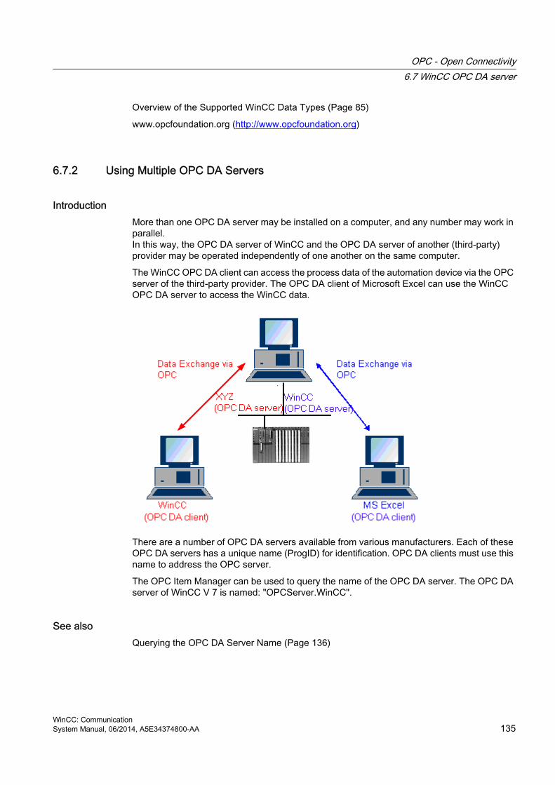
Overview of the Supported WinCC Data Types (Page 85)
www.opcfoundation.org (http://www.opcfoundation.org)
6.7.2 Using Multiple OPC DA Servers
IntroductionMore than one OPC DA server may be installed on a computer, and any number may work in parallel.In this way, the OPC DA server of WinCC and the OPC DA server of another (third-party) provider may be operated independently of one another on the same computer.
The WinCC OPC DA client can access the process data of the automation device via the OPC server of the third-party provider. The OPC DA client of Microsoft Excel can use the WinCC OPC DA server to access the WinCC data.
There are a number of OPC DA servers available from various manufacturers. Each of these OPC DA servers has a unique name (ProgID) for identification. OPC DA clients must use this name to address the OPC server.
The OPC Item Manager can be used to query the name of the OPC DA server. The OPC DA server of WinCC V 7 is named: "OPCServer.WinCC".
See alsoQuerying the OPC DA Server Name (Page 136)
OPC - Open Connectivity6.7 WinCC OPC DA server
WinCC: CommunicationSystem Manual, 06/2014, A5E34374800-AA 135

6.7.3 Querying the OPC DA Server Name
IntroductionMultiple OPC DA servers can be installed on a single computer. The OPC Item Manager displays the names of the OPC DA servers available to the workstation in a selection window. These OPC DA servers can be run on the same computer or on computers in the network environment.
RequirementAdd the "OPC" channel to the WinCC project of the WinCC OPC DA client.
Procedure1. In the shortcut menu of the channel unit "OPC Groups(OPCHN Unit#1)" on the WinCC
OPC DA client, select "System Parameters". The "OPC Item Manager" is opened.
2. In the navigation window of the OPC Item Manager, select the name of the computer you wish to access.
3. The OPC Item Manager displays the names of the OPC DA servers that available to your computer in a selection window.
See alsoOPC Item Manager (Page 81)
OPC - Open Connectivity6.7 WinCC OPC DA server
WinCC: Communication136 System Manual, 06/2014, A5E34374800-AA

6.7.4 Examples of OPC DA Connections
6.7.4.1 WinCC - WinCC Connection
Example of WinCC to WinCC Connection
IntroductionWhen establishing a WinCC - WinCC connection, data are exchanged between the WinCC OPC DA server and client by means of the "OPC_Server_Tag" WinCC tag. The "Client_OPC_Server_Tag_xyz" WinCC tag on the client reads the "OPC_Server_Tag" WinCC tag on the server. If the value of the "OPC_Server_Tag" tag on the WinCC OPC server changes, the value of the "Client_OPC_Server_Tag_xyz" WinCC tag on the WinCC OPC DA client also changes. Changes on the client are also reflect on the server.
Tag values are displayed in I/O fields on both computers.
Requirements● Two computers with WinCC projects.
● Both computers must be accessible via their IP addresses.
Configuration ProcedureThe following configurations are required to establish a WinCC - WinCC connection:
1. Configuring a WinCC Project on a WinCC OPC DA Server
2. Configuring a WinCC Project on a WinCC OPC DA Client
See alsoHow to Configure a WinCC Project on a WinCC OPC DA Server (Page 138)
Configuring the WinCC Project on the WinCC OPC DA Client (Page 138)
OPC - Open Connectivity6.7 WinCC OPC DA server
WinCC: CommunicationSystem Manual, 06/2014, A5E34374800-AA 137

How to Configure a WinCC Project on a WinCC OPC DA Server
IntroductionIn this section, a WinCC tag is created in the WinCC project of the WinCC OPC DA server and displayed in an I/O field.
Procedure1. Select "New Tag" from the shortcut menu of the "Internal Tags" icon on the WinCC OPC
DA server. Create a new tag called "OPC_Server_Tag" of the "signed 16-bit value" type.
2. Launch the Graphics Designer and open a new picture.
3. Add an I/O field to the picture. Select the "I/O field" object from the object list under "Smart Objects". The "I/O Field Configuration" dialog is opened.
4. Enter the name "OPC_Server_Tag" in the "Tag" field.
5. Set the update to "2s" and the field type to "I/O field".
6. Click "OK" to close the dialog and save the picture.
7. Enable the WinCC project by clicking the "Activate" button in the Graphics Designer.
See alsoConfiguring the WinCC Project on the WinCC OPC DA Client (Page 138)
Configuring the WinCC Project on the WinCC OPC DA Client
IntroductionIn this section, a WinCC tag is created on the WinCC OPC DA client, in order to read a WinCC tag on the WinCC OPC DA server. The tag value is displayed in an I/O field.
OPC - Open Connectivity6.7 WinCC OPC DA server
WinCC: Communication138 System Manual, 06/2014, A5E34374800-AA

Requirements● Add the "OPC" channel to the WinCC project of the WinCC OPC DA client.
● Configure an internal tag named "OPC_Server_Tag" of the data type "signed 16-bit value" in the WinCC project of the WinCC OPC DA server.
● Enable the WinCC project of the WinCC OPC DA server.
Procedure1. In the shortcut menu of the channel unit "OPC Groups(OPCHN Unit#1)" on the WinCC
OPC DA client, select "System Parameters". The OPC Item Manager is opened.
2. Choose the name of the computer to be used as the OPC DA server from the selection dialog. Select "OPCServer.WinCC" from the list. Click the "Browse Server" button. The "Filter Criteria" dialog is opened.
3. Click the "Next->" button in the "Filter Criteria" dialog. Select the "OPC_Server_Tag" tag in the "OPCServer.WinCC ..." dialog. Click the "Add Items" button.
4. If a connection to the OPC DA server already exists, continue with step 5.If no connection has been configured, a corresponding message is displayed.Click "Yes". The "New Connection" dialog is displayed.
Enter "OPCServer_WinCC" as the name of the connection. Click "OK".
OPC - Open Connectivity6.7 WinCC OPC DA server
WinCC: CommunicationSystem Manual, 06/2014, A5E34374800-AA 139

5. The "Add Tags" dialog is displayed.Enter "Client_" in the prefix field and "_xyz" in the suffix field. Select connection "OPCServer_WinCC". Click "Finish".
6. Click the "<- Back" button in the "OPCServer.WinCC ..." dialog. In the "OPC Item Manager", click "Exit" to close the OPC Item Manager.
7. Launch the Graphics Designer and open a new picture. Add an I/O field to the picture. Select the "I/O field" object from the object list under "Smart Objects". The "I/O Field Configuration" dialog is opened.
8. Enter the name "Client_OPC_Server_Tag_xyz" in the "Tag" field. Set the update to "2 s". Set the field type to "I/O field". Close the dialog and save the picture. Enable the WinCC project by clicking the "Activate" button in the Graphics Designer.
9. The value of the configured tags is displayed in the I/O field on both the WinCC OPC DA server and the client. Enter a new value in the I/O field on the WinCC OPC DA server. The new value is displayed in the I/O field on the WinCC OPC DA client.
See alsoHow to Configure a WinCC Project on a WinCC OPC DA Server (Page 138)
Configuring the OPC Channel on the WinCC OPC DA Client (Page 88)
OPC - Open Connectivity6.7 WinCC OPC DA server
WinCC: Communication140 System Manual, 06/2014, A5E34374800-AA

6.7.4.2 WinCC - SIMATIC NET FMS OPC Server Connection
Example of WinCC - SIMATIC NET FMS OPC Server Connection
IntroductionDuring the installation of SIMATIC NET, you can select the OPC server to be installed. In the following example, a connection between WinCC and SIMATIC NET FMS OPC server is configured. Data from the automation device is made available to WinCC through the SIMATIC NET FMS OPC server.
In this example, WinCC is used as the WinCC OPC DA client. The OPC Item Manager displays the indexes of the object list configured for the automation device.
The current value of the tag is displayed in an I/O field. As soon as the value of the tags on the SIMATIC NET FMS OPC server changes, the new value is reflected on the process picture on the WinCC OPC DA client. Conversely, a value entered in the I/O field is sent to the automation device.
Requirements● A computer with WinCC, SIMATIC NET software.
● A configured SIMATIC NET FMS OPC server. For additional information regarding the setup of SIMATIC NET S7 OPC servers refer to the SIMATIC NET documentation.
OPC - Open Connectivity6.7 WinCC OPC DA server
WinCC: CommunicationSystem Manual, 06/2014, A5E34374800-AA 141

Configuration stepsThe following configuration is required in the WinCC project of the WinCC OPC DA client:
1. Configuring a WinCC - SIMATIC NET FMS OPC server connection
Communication ManualThe communication manual contains additional information and extensive examples for the channel configuration. This manual is available for download on the Internet:
● http://support.automation.siemens.com/
Search by item number:
● A5E00391327
How to Configure the WinCC - SIMATIC NET FMS OPC Server Connection
IntroductionIn this section, a WinCC tag that accesses an FMS index is configured in the WinCC project of the WinCC OPC DA client. The tag value is displayed in an I/O field.
Requirement● Add the "OPC" channel to the WinCC project of the WinCC OPC DA client.
Procedure1. In the shortcut menu of the channel unit "OPC Groups(OPCHN Unit#1)" on the WinCC
OPC DA client, select "System Parameters". The OPC Item Manager is opened.
2. Choose the name of the computer to be used as the OPC DA server from the selection dialog. Select "OPC.SIMATICNet" from the list.Click the "Browse Server" button. The "Filter Criteria" dialog is opened.
3. Click the "Next->" button in the "Filter Criteria" dialog. The "OPC.SIMATICNet.." dialog is opened. All FMS indexes configured are displayed in a selection list. Select an index. Click the "Add Items" button.
OPC - Open Connectivity6.7 WinCC OPC DA server
WinCC: Communication142 System Manual, 06/2014, A5E34374800-AA

4. If a connection to the SIMATIC NET FMS OPC server already exists, continue with step 5.If no connection has been configured, a corresponding message is displayed.Click "Yes". The "New Connection" dialog is displayed.
Enter "OPC_SIimaticNET" as the name of the connection. Click "OK".
5. The "Add Tags" dialog is opened.Enter "Client_" in the prefix field and "_xyz" in the suffix field. Select the connection "OPC_SimaticNET". Click "Finish".
6. Click the "<- Back" button in the "OPC.SIMATICNet .." dialog. In the "OPC Item Manager", click "Exit" to close the OPC Item Manager.
7. Launch the Graphics Designer and open a new picture. Add an I/O field to the picture. Select the "I/O field" object from the object list under "Smart Objects". The "I/O Field Configuration" dialog is opened.
8. Enter the name of the tags in the "Tag" field. Set the update to "2s". Set the field type to "I/O field".
9. Click "OK" to close the dialog and save the picture. Enable the WinCC project by clicking the "Activate" button in the Graphics Designer.
10.The current value of the FMS index is shown in the I/O field. The value is updated every two seconds. Enter a value in the I/O field. The changed value is passed to the automation device.
See alsoConfiguring the OPC Channel on the WinCC OPC DA Client (Page 88)
6.7.4.3 WinCC - SIMATIC NET S7-OPC Server Connection
Example of a WinCC - SIMATIC NET S7 OPC Server ConnectionDuring the installation of SIMATIC NET, you can select the OPC server to be installed. In the following example, a WinCC - SIMATIC NET S7 OPC server is configured. Data from the automation device is made available to the WinCC client via the SIMATIC NET S7 OPC server.
The current value of the tag is displayed in an I/O field on the WinCC OPC client. As soon as the value of the tags on the SIMATIC NET S7 OPC server changes, the changed value is shown on the process picture. Conversely, a value entered in the I/O field is sent to the automation device.
OPC - Open Connectivity6.7 WinCC OPC DA server
WinCC: CommunicationSystem Manual, 06/2014, A5E34374800-AA 143

Requirements● A computer with WinCC, SIMATIC NET software.
● A configured SIMATIC NET S7 OPC Server. For additional information regarding the setup of SIMATIC NET S7 OPC servers refer to the SIMATIC NET documentation.
Configuration stepsThe following configurations are required to establish a WinCC - SIMATIC NET S7 OPC server connection:
1. Adding Tags to a SIMATIC NET S7 OPC Server
2. Configuring Access to the Tags on a SIMATIC NET S7 OPC Server
Communication ManualThe communication manual contains additional information and extensive examples for the channel configuration. This manual is available for download on the Internet:
● http://support.automation.siemens.com/
Search by item number:
● A5E00391327
OPC - Open Connectivity6.7 WinCC OPC DA server
WinCC: Communication144 System Manual, 06/2014, A5E34374800-AA

Adding Tags to the SIMATIC NET S7 OPC Server
IntroductionIn order for the OPC Item Manager to display the tags, they must be added to the address space of the SIMATIC NET S7 OPC server. The "OPC Scout" program is used for the configuration. OPC Scout is set up by the SIMATIC NET installer. For this example, the marker word "0" in the automation device is addressed.
Table of Parameters Used
Parameter ValueData type WRange byte 0No. values 1Item alias MW0
OPC - Open Connectivity6.7 WinCC OPC DA server
WinCC: CommunicationSystem Manual, 06/2014, A5E34374800-AA 145

Requirements● Configure an S7 connection in the SIMATIC NET software. For more information, refer to
the SIMATIC NET documentation.
Procedure1. Open the "OPC Scout" via Start "Programs" "SimaticNet" "OPCServer"
"OPCScout" .
2. Select "OPC.SimaticNet" under "Local Server(s)". If the SIMATIC S7 OPC server is not run on the same computer, select "Add Remote Server(s)" in the "Server(s)" shortcut menu. Enter the name of the computer used as the OPC server in the "Add Remote Server(s)" dialog, then click "OK" to close the dialog.
3. Select "Connect" in the "OPC.SimaticNet" shortcut menu. The "Add Group" dialog is displayed. Enter a name for the group. Click "OK" to close the dialog.
OPC - Open Connectivity6.7 WinCC OPC DA server
WinCC: Communication146 System Manual, 06/2014, A5E34374800-AA

4. Select "Add Item" from the shortcut menu of the added group. The "OPC Navigator" is opened.
5. Select "M" (marker) under "Objects" in the "OPC Navigator". Double-click "(New Definition)" to open the "Define New Tag" dialog.
6. Enter the parameters from the table in the "Define New Tag" dialog.
Click "OK" to close the "Define New Tag" dialog.
7. Mark the tag "MW0" in the "Leaves" area of the OPC Navigator. Click the "--> " button. Click "OK" in the OPC Navigator.
OPC - Open Connectivity6.7 WinCC OPC DA server
WinCC: CommunicationSystem Manual, 06/2014, A5E34374800-AA 147

See alsoConfiguring Access to the Tags of the SIMATIC NET S7 OPC Server (Page 148)
Configuring Access to the Tags of the SIMATIC NET S7 OPC Server
IntroductionIn this section, a WinCC tag is configured in the WinCC project of the WinCC OPC DA client. This tag accesses the tag "MW0" in the address space of the SIMATIC NET S7 OPC server. The tag value is displayed in an I/O field.
Requirements● Create the tag "MW0" using the OPC Scout.
● Add the "OPC" channel to the WinCC project of the WinCC OPC DA client.
Procedure1. Select "System Parameters" in the shortcut menu of "OPC Groups(OPCHN Unit#1)". The
OPC Item Manager is opened.
2. Choose the name of the computer to be used as the OPC server from the selection dialog. Select "OPC.SIMATICNet" from the list.Click the "Browse Server" button. The "Filter Criteria" dialog is opened.
3. Click the "Next->" button in the "Filter Criteria" dialog. The "OPC.SIMATICNet.." dialog is opened. Select the "MW0" tag. Click the "Add Items" button.
4. If a connection to the SIMATIC NET FMS OPC server already exists, continue with step 5.If no connection has been configured, a corresponding message is displayed.Click "Yes". The "New Connection" dialog is displayed.
Enter "OPC_SIimaticNET" as the name of the connection. Click "OK".
5. The "Add Tags" dialog is opened.Enter "Client_" in the prefix field and "_xyz" in the suffix field. Select the connection "OPC_SimaticNET". Click "Finish".
6. Click the "<- Back" button in the "OPC.SIMATICNet .." dialog. In the "OPC Item Manager", click "Exit" to close the OPC Item Manager.
OPC - Open Connectivity6.7 WinCC OPC DA server
WinCC: Communication148 System Manual, 06/2014, A5E34374800-AA

7. Start Graphics Designer and open a picture. Add an I/O field to the picture. Select the "I/O field" object from the object list under "Smart Objects". The "I/O Field Configuration" dialog is opened.
8. Enter the name "Client_MW0_xyz" in the "Tag" field. Set the update to "2s". Set the field type to "I/O field".
9. Close the dialog and save the picture. Enable the WinCC project by clicking the "Activate" button in the Graphics Designer.
10.The I/O field on the WinCC OPC DA client displays the current value of the S7 tags. The value is updated every two seconds. Enter a value in the I/O field. The changed value is passed to the automation device.
See alsoAdding Tags to the SIMATIC NET S7 OPC Server (Page 145)
Configuring the OPC Channel on the WinCC OPC DA Client (Page 88)
6.7.4.4 WinCC - Microsoft Excel Connection
Example of the WinCC - Microsoft Excel Connection
IntroductionIn this example, an OPC DA client is created in Microsoft Excel using the Visual Basic Editor. The OPC DA client reads a WinCC tag in the WinCC project of the WinCC OPC DA server and writes the value into a cell. If a new value is entered in the cell, the value is passed to the WinCC OPC DA server.
A computer on which both WinCC and Microsoft Excel are installed is used for the connection.
OPC - Open Connectivity6.7 WinCC OPC DA server
WinCC: CommunicationSystem Manual, 06/2014, A5E34374800-AA 149

Configuration stepsThe following configurations must be made in Microsoft Excel:
1. Creating an OPC DA client in Visual Basic Editor of Microsoft Excel
2. Configuring access to a WinCC tag in Microsoft Excel
See alsoHow to Configure the Access to a WinCC Tag in Microsoft Excel (Page 152)
Creating an OPC DA Client in Microsoft Excel (Page 150)
Creating an OPC DA Client in Microsoft Excel
Introduction To use Microsoft Excel as an OPC DA client, a special script must be created in the Visual Basic Editor of Microsoft Excel.
RequirementsBasic knowledge of Visual Basic Editor in Microsoft Excel.
Procedure1. Open Microsoft Excel with a new workbook.
2. In the "Tools" menu of the Visual Basic Editor, click "Macro". The Visual Basic Editor for Microsoft Excel is opened.
3. In the "Tools" menu of the Visual Basic Editor, select "References...". The "References - VBAProject" dialog is displayed. Locate entry "Siemens OPC DAAutomation 2.0" in the list of available references. Select the corresponding check box. Click "OK".
4. Copy the script shown below. This script is only available in the online help.
5. Open a new code window by double-clicking "Sheet1" in the project window of the Visual Basic Editor.
6. Paste the script into the code window.
7. Select "Save" from the "File" menu. Select "Close and Return to Microsoft Excel" from the "File" menu.
Example Script
Option ExplicitOption Base 1
OPC - Open Connectivity6.7 WinCC OPC DA server
WinCC: Communication150 System Manual, 06/2014, A5E34374800-AA

Const ServerName = "OPCServer.WinCC" Dim WithEvents MyOPCServer As OpcServerDim WithEvents MyOPCGroup As OPCGroupDim MyOPCGroupColl As OPCGroupsDim MyOPCItemColl As OPCItemsDim MyOPCItems As OPCItemsDim MyOPCItem As OPCItem Dim ClientHandles(1) As LongDim ServerHandles() As LongDim Values(1) As VariantDim Errors() As LongDim ItemIDs(1) As StringDim GroupName As StringDim NodeName As String '---------------------------------------------------------------------' Sub StartClient()' Purpose: Connect to OPC_server, create group and add item'---------------------------------------------------------------------Sub StartClient() ' On Error GoTo ErrorHandler '----------- We freely can choose a ClientHandle and GroupName ClientHandles(1) = 1 GroupName = "MyGroup" '----------- Get the ItemID from cell "A1" NodeName = Range("A1").Value ItemIDs(1) = Range("A2").Value '----------- Get an instance of the OPC-Server Set MyOPCServer = New OpcServer MyOPCServer.Connect ServerName, NodeName Set MyOPCGroupColl = MyOPCServer.OPCGroups '----------- Set the default active state for adding groups MyOPCGroupColl.DefaultGroupIsActive = True '----------- Add our group to the Collection Set MyOPCGroup = MyOPCGroupColl.Add(GroupName) Set MyOPCItemColl = MyOPCGroup.OPCItems '----------- Add one item, ServerHandles are returned MyOPCItemColl.AddItems 1, ItemIDs, ClientHandles, ServerHandles, Errors '----------- A group that is subscribed receives asynchronous notifications MyOPCGroup.IsSubscribed = True Exit Sub ErrorHandler: MsgBox "Error: " & Err.Description, vbCritical, "ERROR"End Sub '---------------------------------------------------------------------' Sub StopClient()' Purpose: Release the objects and disconnect from the server'---------------------------------------------------------------------Sub StopClient() '----------- Release the Group and Server objects MyOPCGroupColl.RemoveAll
OPC - Open Connectivity6.7 WinCC OPC DA server
WinCC: CommunicationSystem Manual, 06/2014, A5E34374800-AA 151

'----------- Disconnect from the server and clean up MyOPCServer.Disconnect Set MyOPCItemColl = Nothing Set MyOPCGroup = Nothing Set MyOPCGroupColl = Nothing Set MyOPCServer = NothingEnd Sub '---------------------------------------------------------------------' Sub MyOPCGroup_DataChange()' Purpose: This event is fired when a value, quality or timestamp in our Group has changed'---------------------------------------------------------------------'----------- If OPC-DA Automation 2.1 is installed, use:Private Sub MyOPCGroup_DataChange(ByVal TransactionID As Long, ByVal NumItems As Long, ClientHandles() As Long, ItemValues() As Variant, Qualities() As Long, TimeStamps() As Date) '----------- Set the spreadsheet cell values to the values read Range("B2").Value = CStr(ItemValues(1)) Range("C2").Value = Hex(Qualities(1)) Range("D2").Value = CStr(TimeStamps(1))End Sub '---------------------------------------------------------------------' Sub worksheet_change()' Purpose: This event is fired when our worksheet changes, so we can write a new value'---------------------------------------------------------------------Private Sub worksheet_change(ByVal Selection As Range) '----------- Only if cell "B3" changes, write this value If Selection <> Range("B3") Then Exit Sub Values(1) = Selection.Cells.Value '----------- Write the new value in synchronous mode MyOPCGroup.SyncWrite 1, ServerHandles, Values, ErrorsEnd Sub
See alsoHow to Configure a WinCC Project on a WinCC OPC DA Server (Page 138)
How to Configure the Access to a WinCC Tag in Microsoft Excel
IntroductionThe Excel OPC DA client reads a WinCC tag of the WinCC OPC DA server and writes the value of the tag into a cell. In the WinCC project of the WinCC OPC DA server, the value of the tag is displayed in an I/O field. If the tag value in a cell is changed, this alters the value in the I/O field of the WinCC OPC DA server.
OPC - Open Connectivity6.7 WinCC OPC DA server
WinCC: Communication152 System Manual, 06/2014, A5E34374800-AA

Requirements● Configure an internal tag named "OPC_Excel" with data type "signed 16-bit value" in the
WinCC project of the WinCC OPC DA server.
● Write the value of the "OPC_Excel" tag to an I/O field on the WinCC project of the WinCC OPC DA server.
● Enable the WinCC project of the WinCC OPC DA server.
Procedure1. In Microsoft Excel, enter the name of the computer used as the OPC server in cell A1. In
cell A2, enter the tag name "OPC_Excel".
2. In the "Tools" menu in Excel, select "Macro" "Macros". The "Macro" dialog is opened. Select the entry "Sheet1.StartClient" from the list of macros. Click "Run" to start the OPC client.
3. The value of the tag is written into cell B2, the quality code into C2 and the timestamp into D2.
4. Enter a new value in cell B3. The changed value is displayed in the I/O field on the WinCC OPC server.
5. In the "Tools" menu in Excel, select "Macro" "Macros". The "Macro" dialog is opened. Select the entry "Sheet1.StopClient" from the list of macros. Click "Run" to stop the OPC client.
OPC - Open Connectivity6.7 WinCC OPC DA server
WinCC: CommunicationSystem Manual, 06/2014, A5E34374800-AA 153

6.8 WinCC OPC HDA server
6.8.1 Functionality of the WinCC OPC HDA server
Introduction The WinCC OPC HDA server is a DCOM application makings data needed from the archive system available to the OPC HDA client. Access the data using Item Handles. Read or write access is enabled. The data can also be analyzed.
The WinCC OPC HDA server supports the OPC Historical Data Access 1.20 specification. This has been confirmed by the compliance test.
The following chapter explains the design of the data structure, as well as the attributes, aggregates and functions supported by the WinCC OPC HDA server. This is not a detailed description, but rather a summary of the most important information. For more information, refer to the "OPC Historical Data Access 1.20" specification.
InstallationThe WinCC OPC HDA server can be selected during the installation of WinCC. It is possible to select whether access is made to the WinCC archive system with or without write function . After installation, the WinCC OPC DA server is immediately available for use without any additional configuration.
In the case of installation without write access, the data in the WinCC archive system can only be read and analyzed. In the case of write access, data in the WinCC archive system can be analyzed, added, deleted and updated.
The WinCC OPC HDA server can be implemented on a WinCC server or a WinCC client.
LicensingIn order to operate the WinCC OPC HDA server, the following licenses must be installed on each WinCC computer implemented as an OPC HDA server:
● A valid RT license for WinCC
● WinCC Option Connectivity Pack
OPC HDA ClientAll OPC HDA clients that conform to the OPC Historical Data Access 1.20 specification can access the WinCC OPC HDA server. You can also create the OPC HDA client yourself. By creating proprietary OPC HDA clients, most user-specific requirements can be met.
Examples of how an OPC HDA client can be used include:
● Analysis and evaluation of archived data
● Statistical process control of archives from different OPC HDA servers
OPC - Open Connectivity6.8 WinCC OPC HDA server
WinCC: Communication154 System Manual, 06/2014, A5E34374800-AA

To request for historical values using OPC HDA client, you need to take care of the following during configuration:
● Select a query cycle in such a way that the client can receive the requested data before the next query is sent. Too short cycles can lead to high time delays while receiving data.
● CPU load of the WinCC server depends on the number of tags per query.
Write access to cyclic archive with configured swapping outIn runtime, the data is modified in the cyclic archives on the WinCC server.
Changes are accepted into the swapped-out archive only when the data is changed almost immediately after being created.
If the concerned archive segment of the circulation archive has already been swapped out, then the change is not done subsequently in the swapped-out archive. Even the modified data is deleted when you delete the archive segment on the WinCC server.
See alsowww.opcfoundation.org (http://www.opcfoundation.org)
Quality codes (Page 160)
Data Structure of a WinCC OPC HDA Server (Page 155)
6.8.2 Data Structure of a WinCC OPC HDA Server
6.8.2.1 Data Structure of a WinCC OPC HDA Server
IntroductionThe data on the WinCC OPC HDA server are structured. The available data structures are listed below. This is not a detailed description, but rather a summary of the most important information. For more information, refer to the "OPC Historical Data Access 1.20" specification.
Data structure
DescriptionAttributes Provide additional quality characteristics for the raw data. Attributes include data
type, specifications re. archiving, etc. For more information, see the overview of supported attributes.
Assemblies Summarize raw data of a specified time interval. Aggregates include average value, minimum, maximum, etc. For more information, see overview of supported aggregates.
OPC - Open Connectivity6.8 WinCC OPC HDA server
WinCC: CommunicationSystem Manual, 06/2014, A5E34374800-AA 155

DescriptionStartTime/EndTime
Set the beginning and end point for the time interval.
Bounding values Values recorded at the beginning and end. If no bounding values are available, the values closest to these times are used as bounding values.
Raw data Data from the WinCC archive system of a particular time interval. These data include a time stamp and quality rating.
Item handle Unique assignment to a WinCC archive tag. ItemID Unique identifier of the WinCC archive tag. The ItemID can be used to get an item
handle.
See alsowww.opcfoundation.org (http://www.opcfoundation.org)
Overview of the supported functions (Page 158)
Time Format of a WinCC OPC HDA Server (Page 158)
Overview of the supported attributes (Page 156)
Overview of the supported assemblies (Page 157)
6.8.2.2 Overview of the supported attributes
IntroductionThe following table contains the attributes supported by the WinCC OPC HDA server. For more information, refer to the "OPC Historical Data Access 1.20" specification.
Attributes
Attribute Attribute ID DescriptionItemID OPCHDA_ITEMID Indicates the WinCC archive tag to be accessed. Item data type OPCHDA_DATA_TYPE Indicates the data type of the WinCC archive tag.Description OPCHDA_DESCRIPTIO
NReturns a description of the WinCC archive tag. The description is defined in the WinCC Tag Logging.
Engineering units
OPCHDA_ENG_UNITS Sets the display of measurement units. The labeling is defined in the WinCC Tag Logging.
See alsowww.opcfoundation.org (http://www.opcfoundation.org)
Data Structure of a WinCC OPC HDA Server (Page 155)
OPC - Open Connectivity6.8 WinCC OPC HDA server
WinCC: Communication156 System Manual, 06/2014, A5E34374800-AA

6.8.2.3 Overview of the supported assemblies
IntroductionThe following table lists the aggregates supported by the WinCC OPC HDA server. For more information, refer to the "OPC Historical Data Access 1.20" specification.
Assemblies
Assembly DescriptionOPCHDA_COUNT Returns the raw data count for the specified time interval.OPCHDA_START Returns the initial value of the raw data at the beginning of the time
interval.OPCHDA_END Returns the final value of the raw data at the end of the time interval.OPCHDA_AVERAGE Returns the average value of the raw data for the specified time
interval.OPCHDA_TIMEAVERAGE Returns the time-weighted average of the raw data for the specified
time interval.OPCHDA_TOTAL Returns the sum total value for the specified time interval.OPCHDA_STDEV Returns the standard deviation of the raw data for the specified time
interval.OPCHDA_MINIMUMACTUALTIME
Returns the minimum value of the raw data and its time stamp for the specified time interval.
OPCHDA_MINIMUM Returns the minimum value of the raw data for the specified interval.OPCHDA_MAXIMUMACTUALTIME
Returns the maximum value of the raw data and its time stamp for the specified time interval.
OPCHDA_MAXIMUM Returns the maximum value of the raw data for the specified interval.
OPCHDA_DELTA Returns the difference between the first and last value in the raw data for the specified time interval.
OPCHDA_REGSLOPE Returns the slope of the regression line of the raw data for the specified time interval.
OPCHDA_REGCONST Returns the regression value of the raw data at the starting point.OPCHDA_REGDEV Returns the standard deviation of the regression of the raw data in
the specified time interval.OPCHDA_VARIANCE Returns the variance of the raw data for the specified time interval.OPCHDA_RANGE Returns the difference between OPCHDA_MAXIMUM and
OPCHDA_MINIMUM of the raw data for the specified time interval.OPCHDA_DURATIONGOOD Returns the period of time in which the quality of the raw data was
good. The period is indicated in seconds.OPCHDA_DURATIONBAD Returns the period of time in which the quality of the raw data was
bad. The period is indicated in seconds.OPCHDA_PERCENTGOOD Returns the percentage of the raw data of good quality.OPCHDA_PERCENTBAD Returns the percentage of the raw data of bad quality.OPCHDA_WORSTQUALITY Returns the worst quality of the raw data for the specified time
interval.
OPC - Open Connectivity6.8 WinCC OPC HDA server
WinCC: CommunicationSystem Manual, 06/2014, A5E34374800-AA 157

See alsowww.opcfoundation.org (http://www.opcfoundation.org)
Data Structure of a WinCC OPC HDA Server (Page 155)
Functionality of the WinCC OPC HDA server (Page 154)
6.8.2.4 Overview of the supported functions
IntroductionThe following tables list the functions supported by the WinCC OPC HDA server. These functions can be used by the OPC HDA client for data exchange. For more information, refer to the "OPC Historical Data Access 1.20" specification.
Read
Function DescriptionReadRaw Returns the raw data, its quality and time stamp for the specified time interval.ReadProcessed Returns the calculated value, the quality of the value and the time stamp for the
specified time interval. The calculated value is determined by the selected aggregate.ReadAtTime Returns the raw data, its quality and time stamp for a particular time interval. If no
value is available, the value for this point is interpolated.ReadAttribute Returns the item attributes and time stamp for the specified time interval.
See alsowww.opcfoundation.org (http://www.opcfoundation.org)
Functionality of the WinCC OPC HDA server (Page 154)
6.8.2.5 Time Format of a WinCC OPC HDA Server
IntroductionThe time interval is specified on the WinCC OPC HDA server by setting the starting and ending times. The specified time interval determines the observation period for the historical data. When specifying the times, certain formats must be maintained.
The following options are available for the specification of times:
● Absolute based on UTC
● Relative to the local time of the server
OPC - Open Connectivity6.8 WinCC OPC HDA server
WinCC: Communication158 System Manual, 06/2014, A5E34374800-AA

Absolute Value According to UTCBy default, the WinCC OPC HDA server uses the coordinated world time (UTC) as its time base. This time corresponds to the Greenwich Mean Time (Central European Time minus an hour).
Time formatYYYY/MM/DD hh:mm:ss.msmsms
ParametersYYYY = year
MM = month
DD = day
hh = hours
mm = minutes
ss = seconds
ms = milliseconds
Input example2002/06/10 09:27:30.000
Specification of Time Relative to Local TimeFor this option, the time is entered relative to the local time of the server. The local time zone is set on the computer's "Date/Time" control panel.
Time formatkeyword +/-offset1 +/-offset(n)
The offset is the deviation from the local time of the server.
KeywordsNOW = current local time on the server
SECOND = current second
MINUTE = current minute
HOUR = current hour
DAY = current day
WEEK = current week
MONTH = current month
YEAR = current year
Offset+/-S = deviation in seconds
+/-M = deviation in minutes
OPC - Open Connectivity6.8 WinCC OPC HDA server
WinCC: CommunicationSystem Manual, 06/2014, A5E34374800-AA 159

+/-H = deviation in hours
+/-D = deviation in days
+/-W = deviation in weeks
+/-MO = deviation in months
+/-Y = deviation in years
Example:DAY - 1D = previous day
DAY-1D + 7H30 = previous day at 7:30
MO-1D+5H = last day of the previous month at 5:00.
NOW-1H15M = one hour and 15 minutes ago
YEAR+3MO= April of this year
See alsowww.opcfoundation.org (http://www.opcfoundation.org)
Functionality of the WinCC OPC HDA server (Page 154)
6.8.3 Quality codes
Introduction Quality codes are used to evaluate the status and quality of the raw data. The quality codes for OPC are described under "6.8 OPC Quality flags" of the "Data Access Custom Interface Standard Version 3.00" specifications.
Quality Codes of the WinCC OPC HDA Server
Code OPC Description Quality0x00040000 OPCHDA_RAW Indicates the quality of raw data transmission. GOOD
BAD UNCERTAIN
0x00080000 OPCHDA_CALCULATED
Indicates the quality of calculated data transmission.
GOODBADUNCERTAIN
0x00100000 OPCHDA_NOBOUND No bounding values were found at the starting or ending point.
BAD
0x00200000 OPCHDA_NODATA No raw data were found for the specified time interval.
BAD
0x00400000 OPCHDA_DATALOST The raw data in the selected interval were not completely archived.
BAD
OPC - Open Connectivity6.8 WinCC OPC HDA server
WinCC: Communication160 System Manual, 06/2014, A5E34374800-AA

See alsowww.opcfoundation.org (http://www.opcfoundation.org)
6.8.4 Supported Write-Accesses
IntroductionThe following table shows the write accesses supported by the WinCC OPC HDA server.
Table element:
DescriptionCyclic archive The process values to be archived are stored in a cyclic archive. The cyclic archive consists of a
configurable number of data buffers. The size and a period of time (e.g. in days) for the data buffer are defined. If all data buffers are full, the process data in the first data buffer is overwritten.
Cyclic archive after swapping
In order to protect process data in the data buffers from being overwritten process, it can be swapped (exported). Supported by WinCC.
Not supported by WinCC.
Write Accesses
Adding process values later
Cyclic archive
Cyclic archive after swapping
Supportedby WinCC
Description
Yes No When the time period is contained in the cyclic archive, a process value can be added later.
Yes Yes The data buffer of the corresponding time period is swapped to an archive backup. Process values cannot be added later to an archive backup.
No No The cyclic archive is not available. The process value cannot be stored.
No Yes The cyclic archive is not available. The process value cannot be stored.
Adding process values in Runtime
Cyclic archive
Cyclic archive after swapping
Supportedby WinCC
Description
Yes No The process value is added in the data buffer currently valid for the cyclic archive.
OPC - Open Connectivity6.8 WinCC OPC HDA server
WinCC: CommunicationSystem Manual, 06/2014, A5E34374800-AA 161

Inserting future process values
Cyclic archive
Cyclic archive after swapping Supportedby WinCC
Description
YES No During write access, no values can be added in the future.
No No With write access, no values can be added in the future.
Deleting process values
Cyclic archive
Cyclic archive after swapping
Supportedby WinCC
Description
Yes No When the time period is contained in the cyclic archive, a process value can be deleted.
Yes Yes The data buffer of the corresponding time period is swapped to an archive backup. Process values can be deleted from an archive backup.
No No The cyclic archive is not available. The process value cannot be stored.
No Yes The cyclic archive is not available. The process value cannot be stored.
Editing process values
Cyclic archive
Cyclic archive after swapping
Supportedby WinCC
Description
Yes No When the time period is contained in the cyclic archive, a process value can be edited.
Yes Yes The data buffer of the corresponding time period is swapped to an archive backup. Process values cannot be edited in an archive backup.
No No The cyclic archive is not available. The process value cannot be stored.
No Yes The cyclic archive is not available. The process value cannot be stored.
OPC - Open Connectivity6.8 WinCC OPC HDA server
WinCC: Communication162 System Manual, 06/2014, A5E34374800-AA

6.8.5 Example of an OPC HDA Connection
6.8.5.1 Example of an OPC HDA Connection
IntroductionIn the example below, a connection between WinCC and the OPC HDA client is configured. Data from the WinCC archive system are made available via the WinCC OPC HDA server. The OPC HDA client accesses the data via item handles. To simplify the configuration process, the OPC HDA browser is used.
The OPC HDA client from the OPC Foundation is used. All OPC HDA clients conforming to the OPC Historical Data Access 1.20 specification can access the WinCC OPC HDA server.
Requirements● Create an internal tag named "OPC_HDA" with data type "unsigned 16-bit value" in the
WinCC project of the WinCC OPC HDA server.
● Create a process value archive called "HDA_ProcessValueArchive" in the WinCC archive system.
● Create an WinCC archive tag called "OPC_HDA_Tag" in the "HDA_ProcessValueArchive" process value archive. Link the WinCC archive tag to the internal tag "OPC_HDA".
● In the Runtime list, launch Tag Logging Runtime and disable Graphics Runtime.
● Launch the WinCC project of the WinCC OPC HDA server.
Configuration stepsThe following configurations are required to connect WinCC to the OPC HDA client:
1. Configuring access to a WinCC archive tag using the HDA server browser
2. Reading values from the WinCC archive tags
See alsoHow to Configure Access to a WinCC Archive Tag Using the HDA Server Browser (Page 165)
HDA server browser (Page 164)
Reading Values of WinCC Archive Tags (Page 166)
OPC - Open Connectivity6.8 WinCC OPC HDA server
WinCC: CommunicationSystem Manual, 06/2014, A5E34374800-AA 163

6.8.5.2 HDA server browser
IntroductionThe OPC HDA client accesses the tag values via item handles. For ease of configuration, the WinCC OPC HDA server supports the browser functionality. The OPC HDA client can use the HDA server browser to search the address space of the WinCC OPC HDA server. The data are listed hierarchically by process value archive.
Note
Access to a WinCC archive tag without the HDA server browser requires manual configuration of the item ID.
When addressing WinCC archive tags, the computer name (server prefix) is included in the path. The ItemID has the following syntax: Server-prefix::process_value_archive\WinCC_archive_tag.
OPC - Open Connectivity6.8 WinCC OPC HDA server
WinCC: Communication164 System Manual, 06/2014, A5E34374800-AA

See alsowww.opcfoundation.org (http://www.opcfoundation.org)
How to Configure Access to a WinCC Archive Tag Using the HDA Server Browser (Page 165)
6.8.5.3 How to Configure Access to a WinCC Archive Tag Using the HDA Server Browser
IntroductionIn this section, the OPC HDA client is used to access a WinCC archive tag. The OPC HDA client from the OPC Foundation is used. The HDA server browser is used to configure access.
Note
The OPC HDA client described here is the demo client from the OPC Foundation. The source code for it is found on the Internet at http://www.opcfoundation.org.
Procedure1. Copy the "SampleClientHDA.exe" file from the folder "Siemens\WinCC\documents\english"
to a folder of your choice.
2. Double-click the "SampleClientHDA.exe" file. The HDA client program is started.
3. In the "Server Name" area, select entry "OPCServerHDA.WinCC.1". Click "Connect". Confirm the next dialog.
OPC - Open Connectivity6.8 WinCC OPC HDA server
WinCC: CommunicationSystem Manual, 06/2014, A5E34374800-AA 165

4. Click "Browse" in the HDA client. The "Browse Dialog" dialog is opened. Select "OPCHDA_FLAT" in the "OPCHDA_BROWSETYPE" field.
5. In the selection window, select entry "HDA_ProcessValueArchive_HDA_TAG". Click "Add" and then "Done" to close the dialog.
For more information, refer to http://www.opcfoundation.org.
See alsoReading Values of WinCC Archive Tags (Page 166)
SampleClientHDA.exe
www.opcfoundation.org (http://www.opcfoundation.org)
6.8.5.4 Reading Values of WinCC Archive Tags
IntroductionThis section explains how you can access and read WinCC archive tags.
OPC - Open Connectivity6.8 WinCC OPC HDA server
WinCC: Communication166 System Manual, 06/2014, A5E34374800-AA

Requirement● The OPC HDA client must be running.
Procedure1. Click "Show Items" in the HDA client.
2. Click "Get Item Handles" in the HDA client.
3. Double-click "HDA_ProcessValueArchive_HDA_Tag" in the selection field "Value" selection field.
4. Enter "NOW-10S" in the "Start Time" field. Enter "NOW" in the "End Time" field.
5. Click "Read Raw". The values, their quality codes and time stamps are shown in the "Values" selection field.
OPC - Open Connectivity6.8 WinCC OPC HDA server
WinCC: CommunicationSystem Manual, 06/2014, A5E34374800-AA 167

6.8.6 Special features of the OPC HDA server in WinCC for acyclic logging
IntroductionTag logging is performed in WinCC cyclically or acyclically. The WinCC OPC HDA server works differently depending on the logging method for tags:
● For all cyclically logged values, the OPC HDA server operates in conformity to the HDA specification of the OPC foundation. The OPC aggregates are linearly interpolated.
● Acyclically logged tags are not included in the HDA specification of the OPC Foundation. The OPC aggregates are interpolated incrementally. Especially when a tag experiences no change for a long period of time, no data is available during a time period. The following should be taken into consideration to nevertheless obtain valid data.
Note
The OPC HDA server is not OPC-compliant for acyclically logged tags. The HDA specification of the OPC Foundation does not recognize acyclically logged tags and, therefore, no archive server can handle acyclically logged tags. The supported aggregates are calculated in conformity to the OPC HDA specification. No non-explicitly called functions are supported.
Note
If write access to process value archives is enabled, no future values may be added.
Configuration of acyclically logged tagsFor the configuration of acyclically logged tags, the "Archive after segment change" setting needs to be enabled for the tags. This enters the most recent valid value in the the new log when a segment changes.
Supported aggregates of the WinCC OPC HDA server for acyclically logged tagsThe OPC HDA server supports the following aggregates:
● OPCHDA_MINIMUM
● OPCHDA_MAXIMUM
● OPCHDA_AVERAGE
● OPCHDA_END
● OPCHDA_INTERPOLATIVE
● OPCHDA_TIMEAVERAGE
● OPCHDA_TOTAL
● OPCHDA_DURATIONGOOD
● OPCHDA_PERCENTGOOD
OPC - Open Connectivity6.8 WinCC OPC HDA server
WinCC: Communication168 System Manual, 06/2014, A5E34374800-AA

Supported functions of the WinCC OPC HDA server for acyclically logged tags● ReadRaw with "boundings" only. ReadRaw for a tag must always be performed with
"boundings", in order to find the last real stored value for an area without logged value change.
● ReadProcessed
● DeleteRaw
● DeleteAtTime
● Insert
● InsertReplace
● Replace
Calculating the aggregates for acyclically logged tagsCalculation of the aggregates is based on the extended "RawData" data record, which contains virtual data points for the calculation in addition to real stored values. The WinCC OPC HDA server prepares the contained "RawData" corresponding to the requirements of the "ReadProcessed". The virtual data points needed for the calculation are formed from the bordering real data points. The following significant points are included for the virtual data points:
● Value for the "StartTime"
● Value for the "EndTime"
● Value for interval limits
ExampleThe values for "00:59:00", "01:02:00" and "01:03:00" are stored for an acyclical tag logging tags. An OPC HDA client postulates with "ReadProcessed" an aggregate with the following parameters:
● StartTime = 01:00:00
● EndTime = 01:04:00
● Interval = 00:02:00
Note
The time period is always 1 µs less than the time stamp at the limit for the calculation when generating virtual values at limits ("EndTime"/"Interval").
A delta of 1 seconds is used in the following table to provide a better overview. The following graphic illustrates the example.
The OPC server uses the following "RawData" for the calculation of the aggregate:
OPC - Open Connectivity6.8 WinCC OPC HDA server
WinCC: CommunicationSystem Manual, 06/2014, A5E34374800-AA 169

Number Time stamp Real stored values Generated virtual values1 00:59:00 1.00 2 01:00:00 1.003 01:01:59 1.004 01:02:00 2.00 5 01:02:59 2.006 01:03:00 3.00 7 01:03:59 3.00
OPC - Open Connectivity6.8 WinCC OPC HDA server
WinCC: Communication170 System Manual, 06/2014, A5E34374800-AA

6.9 WinCC OPC A&E Server
6.9.1 Functionality of the WinCC OPC A&E server
Introduction The WinCC OPC A&E server is a DCOM application. The OPC A&E client is kept informed of status changes for WinCC messages by means of subscriptions. The OPC A&E client can apply a filter to the subscription. This filter determines which messages and attributes are displayed.
The WinCC OPC A&E server supports the specification OPC Alarm&Event 1.10. This has been confirmed by the compliance test.
The following chapter explains the display of the WinCC message system on OPC A&E, as well as the attributes supported by the WinCC OPC A&E server. This is not a detailed description, but rather a summary of the most important information. For more information, refer to the "OPC Alarms & Events 1.10" specification.
InstallationThe WinCC OPC A&E server can be selected during the installation of WinCC. After installation, the WinCC OPC A&E server is immediately available for use without any additional configuration.
As of WinCC V6.2, the WinCC OPC A&E server can be used on a WinCC server and a WinCC client.
LicensingIn order to operate the WinCC OPC A&E server, the following licenses must be installed on each WinCC server implemented as an OPC A&E server:
● A valid RT license for WinCC
● WinCC Option Connectivity Pack
Server typesThe WinCC OPC A&E server supports conditional events and simple events. In addition, there are tracking events.
Condition-related event serverWith a condition-related event server, the event is associated with a condition. A condition might, for example, be a limit value violation of a tag. A message is generated in WinCC as soon as the bounding value is exceeded. This message is shown as an alarm in OPC A&E.
OPC - Open Connectivity6.9 WinCC OPC A&E Server
WinCC: CommunicationSystem Manual, 06/2014, A5E34374800-AA 171

Simple event serverSimple events are messages that inform the OPC A&E client about events. Simple events include, for example, starting or exiting programs.
Note
Note the following when using redundant systems:
Simple events interconnected to internal tags are sent twice when tags are updated.
The first message is triggered by the master, the second by the standby.
Tracking event serverIf a change in a process occurs, the OPC A&E client receives a message. Such a change might for example be a regulator adjustment.
OPC A&E clientAll OPC A&E clients conforming to the OPC Alarms & Events 1.10 specification can access the WinCC OPC A&E server. You can also create the OPC A&E client yourself. By creating proprietary OPC clients, most user-specific requirements can be met. An OPC A&E client can, for example, be used for the analysis and common archiving of alarms from multiple OPC A&E servers.
See alsowww.opcfoundation.org (http://www.opcfoundation.org)
Quality Codes for OPC A&E (Page 178)
Mapping of the WinCC Message System on OPC A&E (Page 172)
6.9.2 Mapping of the WinCC Message System on OPC A&E
6.9.2.1 Mapping of the WinCC Message System on OPC A&E
IntroductionDuring the configuration of the WinCC message system, settings are made to determine which process events generate a message. This message is shown as an alarm in OPC A&E. The table below lists the most important parameters of the alarm. It also describes how the information is made available by the WinCC message system. For more information, refer to "Alarm Structure".
OPC - Open Connectivity6.9 WinCC OPC A&E Server
WinCC: Communication172 System Manual, 06/2014, A5E34374800-AA

Overview
OPC WinCC message system Source Indicates the source of the message. The source has the format "<server
prefix>::@LOCALMACHINE::".Time Issues a time stamp for received, sent and acknowledged messages. Issues a
time stamp in UTC (Universal Time Coordinated).Type Indicates whether the event is a simple, tracking or condition-related event.
WinCC - POC A&E server supports simple, condition-related and tracking events.Severity Indicates the priority of the WinCC message.EventCategory Returns the category of the message. For more information on this topic, refer
to "Displaying Message Classes and Types".Message Indicates the message text of the corresponding message number.ConditionName Indicates the message number.ChangeMask Indicates the changed status of the message. For more information, refer to
"Acknowledgement Theory".NewState Returns the message status. For more information, refer to "Acknowledgement
Theory".ConditionQuality Returns the quality of the message. For more information, refer to "Quality
Codes".AckRequired Indicates whether the message requires acknowledgement (receipt).ActiveTime Returns the time stamp for received messages.EventAttribute Lists the attributes required for the respective message. For more information,
refer to "Attributes of the WinCC Message System".Quality Returns the quality code of the message.Cookie Returns the cookie from the OPC A&E server. The cookie corresponds to the
message number in the WinCC alarm system
See alsoAcknowledgement theory (Page 176)
Attributes of the WinCC Message System (Page 174)
Mapping the WinCC message classes and message types (Page 173)
6.9.2.2 Mapping the WinCC message classes and message types
Introduction The WinCC message system informs the user of disturbances and operating conditions in the process. A WinCC message always belongs to a specific message class and message type that is related to the event category.
The mapping of the WinCC message system on OPC is configured via the "CcAeProvider.ini" file.
OPC - Open Connectivity6.9 WinCC OPC A&E Server
WinCC: CommunicationSystem Manual, 06/2014, A5E34374800-AA 173

Event CategoryAn event category is created on the WinCC OPC A&E server for every combination of a message class and type.
An event category is determined by a category ID and a descriptive "Category Description". The category ID is composed of the WinCC internal IDs for the message class and the message type; the category description is composed of the message class and message type.
Note
If the OPC A&E server is run on a WinCC client of a connectivity station, the OS servers linked to it must have an identical configuration of message classes and message types. If this is not the case, the OPC client used must access the OS server directly.
The names of the message classes and message types can be ascertained exactly via the alarm attributes "CLASSNAME" and "TYPENAME".
6.9.2.3 Mapping the WinCC message priority
IntroductionThe priority of WinCC messages is displayed by the OPC server to the attribute "Severity".
When configuring alarms in the WinCC messaging system, you can configure a priority between 0 and 16. The OPC A&E specification defines a value range from 1 to 1000 for the severity where 1 stands for the lowest and 1000 for the highest severity.
Therefore, the values of the WinCC priority are suitably displayed to the OPC severity. In the standard mapping, the WinCC priority 0 becomes OPC severity 1. All other priority values are interpolated in a linear manner up to severity 1000. Other priority mapping rules can be configured in the CcAeProvider.ini file.
6.9.2.4 Attributes of the WinCC Message System
IntroductionThe following table lists the OPC attributes of the WinCC message system. The attributes are configured in the WinCC message system. Some attributes are intended for internal use in WinCC only and are therefore not relevant to an OPC A&E client. These attributes are not listed.
Attributes
OPC attributes WinCC message system Data typeCLASSNAME Returns the message class name. VT_BSTRTYPENAME Returns the message type name. VT_BSTR
OPC - Open Connectivity6.9 WinCC OPC A&E Server
WinCC: Communication174 System Manual, 06/2014, A5E34374800-AA

OPC attributes WinCC message system Data typeFORECOLOR Returns the text color for the display of received, sent and
acknowledged messages.VT_I4
BACKCOLOR Returns the background color for the display of received, sent and acknowledged messages.
VT_I4
FLASHCOLOR Returns the flashing color. VT_I4FLAGS Indicates whether the message requires acknowledgment
(receipt). VT_I4
TEXT01 Returns the content of UserTextBlock01. VT_BSTRTEXT02 Returns the content of UserTextBlock02. VT_BSTRTEXT03 Returns the content of UserTextBlock03. VT_BSTRTEXT04 Returns the content of UserTextBlock04. VT_BSTRTEXT05 Returns the content of UserTextBlock05. VT_BSTRTEXT06 Returns the content of UserTextBlock06. VT_BSTRTEXT07 Returns the content of UserTextBlock07. VT_BSTRTEXT08 Returns the content of UserTextBlock08. VT_BSTRTEXT09 Returns the content of UserTextBlock09. VT_BSTRTEXT10 Returns the content of UserTextBlock10. VT_BSTRPROCESSVALUE01
Returns the content of ProcessValueBlock01. VT_VARIANT
PROCESSVALUE02
Returns the content of ProcessValueBlock02. VT_VARIANT
PROCESSVALUE03
Returns the content of ProcessValueBlock03. VT_VARIANT
PROCESSVALUE04
Returns the content of ProcessValueBlock04. VT_VARIANT
PROCESSVALUE05
Returns the content of ProcessValueBlock05. VT_VARIANT
PROCESSVALUE06
Returns the content of ProcessValueBlock06. VT_VARIANT
PROCESSVALUE07
Returns the content of ProcessValueBlock07. VT_VARIANT
PROCESSVALUE08
Returns the content of ProcessValueBlock08. VT_VARIANT
PROCESSVALUE09
Returns the content of ProcessValueBlock09. VT_VARIANT
PROCESSVALUE10
Returns the content of ProcessValueBlock10. VT_VARIANT
STATETEXT Returns the status message. VT_BSTRINFOTEXT Returns the information text for the message. VT_BSTRLOOPINALARM States if LoopInAlarm has been configured. VT_I4CLASSID Returns the message class ID. VT_I4TYPEID Returns the message type ID. VT_I4MODIFYSTATE Outputs the value of the status tag of the message. VT_I4AGNR Returns the number of the automation device that generated
the message.VT_I2
CPUNR Returns the number of the CPU that generated the message. VT_I2
OPC - Open Connectivity6.9 WinCC OPC A&E Server
WinCC: CommunicationSystem Manual, 06/2014, A5E34374800-AA 175

OPC attributes WinCC message system Data typeDURATION Indicates the period of time between message received, sent
and acknowledged.VT_I4
COUNTER Outputs the number of messages after the start of Runtime. VT_I4QUITSTATETEXT
Indicates whether the message has been acknowledged. VT_BSTR
QUITCOUNT Outputs the number of active, unacknowledged messages. VT_I4PARAMETER Outputs the message parameter. (image of the message
configuration).VT_BSTR
BLOCKINFO Returns the current content of the message block. VT_BSTRALARMCOUNT Outputs the number of messages pending. VT_I4LOCKCOUNT Outputs the number of locked messages. VT_I4PRIORITY Indicates the configured priority of the message. VT_I4APPLICATION Outputs the application which triggered the message. VT_BSTRCOMPUTER Outputs the name of the computer which processed the
message.VT_BSTR
USER Outputs the name of the user who processed the message. VT_BSTRCOMMENT Outputs the message comment. VT_BSTR
6.9.2.5 Acknowledgement theory
IntroductionFor WinCC, the acknowledgment philosophy is how a message is displayed and processed from "came in" to "went out". On the WinCC OPC A&E server, this message status is managed in parameters "ChangeMask" and "NewState".
Conditional, Simple and Tracking EventsTypically, messages from the WinCC system are sent to the client as conditional events. In order for a message to be treated as a simple event, the following conditions must be met during configuration of the message class:
● "Acknowledgment Came In" is not activated.
● "Message Without Status Went Out" is activated.
Depending on the mapping configuration, the messages of the message class "System without Acknowledgement" and of the message type "Operations message" are transferred as OPC Tracking Events.
ChangeMaskThe "ChangeMask" parameter keeps track of where the message status was changed.
OPC - Open Connectivity6.9 WinCC OPC A&E Server
WinCC: Communication176 System Manual, 06/2014, A5E34374800-AA

Parameter values:● OPC_CHANGE_ACTIVE_STATE
● OPC_CHANGE_ENABLE_STATE
● OPC_CHANGE_ACK_STATE
NewStateThe "NewState" parameter indicates the message status after a change.
Parameter values:● OPC_CONDITION_ACTIVE
● OPC_CONDITION_ENABLED
● OPC_CONDITION_ACKED
Overview
WinCC NewState ChangeStateReceived message OPC_CONDITION_ACTIVE
OPC_CONDITION_ENABLEDOPC_CHANGE_ACTIVE_STATE
Sent message with receipt OPC_CONDITION_ACTIVEOPC_CONDITION_ENABLED
OPC_CHANGE_ACTIVE_STATE
Sent message without receipt OPC_CONDITION_ENABLED OPC_CHANGE_ACTIVE_STATE
Acknowledged messages (message pending)
OPC_CONDITION_ACTIVEOPC_CONDITION_ACKEDOPC_CONDITION_ENABLED
OPC_CHANGE_ACK_STATE
Acknowledged messages (message no longer pending)
OPC_CONDITION_ACTIVEOPC_CONDITION_ENABLED
OPC_CHANGE_ACK_STATE
Locked message -------------------------------------- OPC_CHANGE_ENABLED_STATE
Unlocked message OPC_CONDITION_ENABLED OPC_CHANGE_ENABLED_STATE
Received, acknowledged message
OPC_CONDITION_ACTIVEOPC_CONDITION_ACKEDOPC_CONDITION_ENABLED
OPC_CHANGE_ACTIVE_STATE
Received, sent message with receipt
OPC_CONDITION_ACTIVEOPC_CONDITION_ENABLED
OPC_CHANGE_ACK_STATE
Received, sent message without receipt
OPC_CONDITION_ENABLED OPC_CHANGE_ACK_STATE
Message acknowledged by the system (message pending)
OPC_CONDITION_ACTIVEOPC_CONDITION_ACKEDOPC_CONDITION_ENABLED
OPC_CHANGE_ACK_STATE
Message acknowledged by the system (message no longer pending)
OPC_CONDITION_ACTIVEOPC_CONDITION_ENABLED
OPC_CHANGE_ACK_STATE
OPC - Open Connectivity6.9 WinCC OPC A&E Server
WinCC: CommunicationSystem Manual, 06/2014, A5E34374800-AA 177

WinCC NewState ChangeStateEmergency-acknowledged message (message pending)
OPC_CONDITION_ACTIVEOPC_CONDITION_ACKEDOPC_CONDITION_ENABLED
OPC_CHANGE_ACK_STATE
Emergency-acknowledged message (message no longer pending)
OPC_CONDITION_ACTIVEOPC_CONDITION_ENABLED
OPC_CHANGE_ACK_STATE
See alsowww.opcfoundation.org (http://www.opcfoundation.org)
6.9.3 Quality Codes for OPC A&E
Introduction Quality codes are used to evaluate the status and quality of a message. The quality codes for OPC are described under "6.8 OPC Quality flags" of the "Data Access Custom Interface Standard Version 3.00" specifications.
Quality codes
Code Quality Status0xC0 OPC_GOOD OK0x40 OPC_UNCERTAIN Returned in cases of uncertainty, e.g. in the
event of delayed acknowledgement (receipt).
0x00 OPC_BAD Returned if the connection to the source is interrupted.
6.9.4 Example of an OPC A&E Connection
6.9.4.1 Example of an OPC A&E Connection
Introduction In the example below, a connection between WinCC and an OPC A&E client is configured. Data from the WinCC message system are made available via the WinCC OPC A&E server.
The OPC A&E client is kept informed of status changes of WinCC messages by means of a subscription.
OPC - Open Connectivity6.9 WinCC OPC A&E Server
WinCC: Communication178 System Manual, 06/2014, A5E34374800-AA

All OPC A&E clients conforming to the OPC Alarms&Events 1.10 specifications can access the WinCC OPC A&E server.
Configuration StepThe following configurations are required for connection between WinCC and the OPC A&E client:
1. Configuring access to the WinCC message system
See alsoHow to Configure Access to the WinCC Message System (Page 179)
www.opcfoundation.org (http://www.opcfoundation.org)
6.9.4.2 How to Configure Access to the WinCC Message System
IntroductionIn this section, the OPC A&E client of the OPC foundation accesses the WinCC message system.
Note
The OPC A&E client described here is the demo client from the OPC Foundation. The source code for it is found on the Internet at http://www.opcfoundation.org.
Requirement● Create several internal tags of the "binary" data type in the WinCC project of the WinCC
OPC A&E server.
● Configure the WinCC message system in the WinCC project of the WinCC OPC A&E server. Link the messages to the internal tags.
● Configure a picture with the Graphics Designer. Add the WinCC alarm control and an I/O field to the picture. Link the message tags to the graphic objects.
● Enable the "Alarm Logging Runtime" in the start list.
● Enable the WinCC project of the WinCC OPC A&E server.
Procedure1. Copy the "SampleClientAE.exe" file from the folder "Siemens\WinCC\documents\english"
to a folder of your choice. This application is only available in the online help.
2. Select "OPC" >"Connect..." in the menu bar. Select "OPC.WinCC-AlarmsEvent" in the "OPC Alarm Server" dialog. Click "OK" to close the dialog.
OPC - Open Connectivity6.9 WinCC OPC A&E Server
WinCC: CommunicationSystem Manual, 06/2014, A5E34374800-AA 179
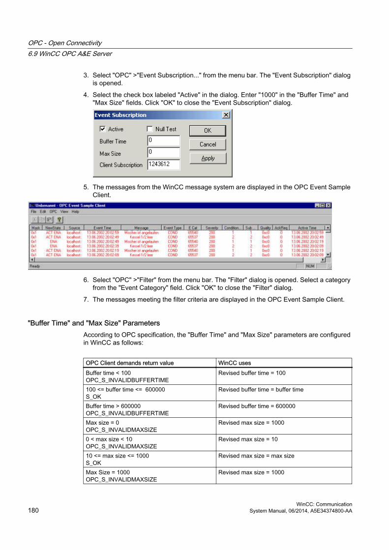
3. Select "OPC" >"Event Subscription..." from the menu bar. The "Event Subscription" dialog is opened.
4. Select the check box labeled "Active" in the dialog. Enter "1000" in the "Buffer Time" and "Max Size" fields. Click "OK" to close the "Event Subscription" dialog.
5. The messages from the WinCC message system are displayed in the OPC Event Sample Client.
6. Select "OPC" >"Filter" from the menu bar. The "Filter" dialog is opened. Select a category from the "Event Category" field. Click "OK" to close the "Filter" dialog.
7. The messages meeting the filter criteria are displayed in the OPC Event Sample Client.
"Buffer Time" and "Max Size" ParametersAccording to OPC specification, the "Buffer Time" and "Max Size" parameters are configured in WinCC as follows:
OPC Client demands return value WinCC usesBuffer time < 100OPC_S_INVALIDBUFFERTIME
Revised buffer time = 100
100 <= buffer time <= 600000S_OK
Revised buffer time = buffer time
Buffer time > 600000OPC_S_INVALIDBUFFERTIME
Revised buffer time = 600000
Max size = 0OPC_S_INVALIDMAXSIZE
Revised max size = 1000
0 < max size < 10OPC_S_INVALIDMAXSIZE
Revised max size = 10
10 <= max size <= 1000S_OK
Revised max size = max size
Max Size = 1000OPC_S_INVALIDMAXSIZE
Revised max size = 1000
OPC - Open Connectivity6.9 WinCC OPC A&E Server
WinCC: Communication180 System Manual, 06/2014, A5E34374800-AA

Parameters may be set while creating a subscription. However, you cannot change an existing subscription using SetState() after the fact.
For more information, refer to http://www.opcfoundation.org.
See alsowww.opcfoundation.org (http://www.opcfoundation.org)
6.9.5 OPC A&E server with hierarchical access
6.9.5.1 Functionality of the OPC A&E server
Introduction The OPC-A&E server uses DCOM services for transferring messages between OPC-capable applications. The OPC A&E server supports the specification OPC Alarm&Event 1.10.
The following chapter explains the mapping of the WinCC message system on OPC A&E with hierarchical access and the attributes supported by the OPC A&E server. This documentation includes an overview of the specific information. For more information, refer to the "OPC Alarms & Events 1.10" specification.
Principle of operationThe OPC-A&E client receives WinCC messages via subscription. You can use the subscription filter to reduce the number of events that will be transferred with a subscription. The OPC-A&E client can be set for every event category that displays message attributes.
InstallationThe WinCC OPC A&E server can be selected during the installation of WinCC. After installation, the WinCC OPC A&E server is immediately available for use without any additional configuration.
As of WinCC V6.2, the WinCC OPC A&E server can be used on a WinCC server and a WinCC client.
LicensingIn order to operate the OPC A&E server, one of the following licenses must be installed on each computer running an OPC A&E server:
● A valid RT license for WinCC
● WinCC Option Connectivity Pack
OPC - Open Connectivity6.9 WinCC OPC A&E Server
WinCC: CommunicationSystem Manual, 06/2014, A5E34374800-AA 181

Event typesThe OPC-A&E server with hierarchical access supports conditional events, simple events and tracking events.
Condition related events With a condition related event, the event is associated with a condition. A condition might, for example, be a limit value violation of a tag. This limit violation generates a message that is shown as an alarm with OPC A&E.
Simple events Simple events are messages that inform the OPC A&E client about events. Simple events include, for example, starting or exiting programs.
Note
Note the following when using redundant systems:
Simple events interconnected to internal tags are sent twice when tags are updated.
The first message is triggered by the master, the second by the standby.
Tracking eventsA tracking event is sent with a operator input message to the OPC A&E client. An operator input message is triggered by manual intervention in the process.
OPC A&E clientAll OPC A&E clients conforming to the OPC Alarms & Events 1.10 specification can access the OPC A&E server. You can also create the OPC A&E client yourself. By creating proprietary OPC clients, most user-specific requirements can be met. An OPC A&E client, for example, may be used for analysis and joint archiving of alarms from different OPC A&E servers. The acknowledgement of archived messages is not possible; only current alarms and events can be acknowledged.
NoteDocumentation on OPC
You can find additional information on OPC in the Chapter "Interfaces > OPC - OLE for Process Control".
OPC - Open Connectivity6.9 WinCC OPC A&E Server
WinCC: Communication182 System Manual, 06/2014, A5E34374800-AA

6.9.5.2 OPC A&E Server of WinCC V6.2 SP2 or higher
Differences between OPC A&E and OPC A&E with hierarchical access
Displaying messages with OPC A&EThe OPC A&E server supports "conditional events" and "simple events" for accessing the message system. With "conditional events", the message numbers are shown for each source. Since an WinCC server can hold many more message numbers, it is difficult to maintain an overview of the messages.
The following figure shows an example of the display in an OPC browser:
Displaying the messages with OPC A&E and hierarchical accessThe OPC A&E server with hierarchical access supports the event types, conditional events, simple events and tracking events.
The user text block 2 determines the source of the messages for "conditional events". With the default setting, user text block 2 corresponds to the fault location. In order to present messages hierarchically, they must be combined in user-defined group messages in alarm logging messages. The structure of group messages is determined by the areas in OPC A&E.
Tracking events occur when operator input messages are triggered in the system.
The following figure shows an example of the display of conditional events in an OPC browser. The "Condition" is shown in addition to "Area" and "Source":
OPC - Open Connectivity6.9 WinCC OPC A&E Server
WinCC: CommunicationSystem Manual, 06/2014, A5E34374800-AA 183

RecommendationUse an OPC A&E server with hierarchical access when creating a new project.
After a project upgrade to WinCC V6.2 SP2 or higher, OPC A&E Server can be used as before, or be converted for hierarchical access. The conversion can be undone again without any loss of data. For further information, refer to "How to upgrade OPC A&E to WinCC V6.2 SP2 or higher".
How to upgrade OPC A&E to WinCC V6.2 SP2 or higher
IntroductionOPC A&E for WinCC V6.2 SP2 or higher was enhanced with functions for hierarchical access to the message system. The OPC-A&E server with non-hierarchical access remains the standard.
Upgrading from OPC A&EIf you are using the OPC A&E with hierarchical access and want to use all functions, you may need to adapt the OPC A&E client currently used.
Starting with the WinCC version of your project, possible upgrade scenarios are described for OPC A&E:
● Upgrading the project from WinCC V6.2 to WinCC V6.2 SP2
● The project is created in WinCC V6.2 SP2 or higher.
OPC - Open Connectivity6.9 WinCC OPC A&E Server
WinCC: Communication184 System Manual, 06/2014, A5E34374800-AA

Upgrading from WinCC V6.2 to WinCC V6.2 SP2You can upgrade a project with WinCC V6.2 to WinCC V6.2 SP2 in regard to OPC A&E as follows:
Retaining previous OPC A&E without hierarchical accessIf you want to continue to work with the previously used OPC A&E server, the following scenarios are possible:
● If you have not changed the standard "CcAeProvider.ini" file, you do not need to make any other settings.
● If you have changed the standard "CcAeProvider.ini" file and want to keep these changes, proceed as follows:
– Save the "CcAeProvider.ini" file from the WinCC installation path in the "OPC\AlarmEvent\bin" folder.If you are working on a distributed system or a system integrated in STEP 7, save the file from the project on the WinCC client or on the OS.
– Following the upgrade, copy the file into the WinCC project directory.If you are working on a distributed system or a system integrated in STEP 7, copy the file on the WinCC server or on the ES into the project directory of the client projects or OS projects.
● If you have changed the standard "CcAeProvider.ini" file and want to replace it with the standard "CcAeProvider.ini" file supplied with the product, before the upgrade delete these files on the servers and clients or on the ES computers and OS computers. The project folder is located in "wincproj" sub-folder on the ES.
Switching to OPC A&E with hierarchical accessIf you want to work with the OPC A&E server with hierarchical access, proceed as follows:
1. After upgrading, copy the "CcAeProvider.ini" file to the project folder. The file is located in the WinCC installation path in the folder "OPC\AlarmEvent\Hierarchical-Access".
2. Update the clients or perform a complete download for the OS servers.
Creating a project in WinCC V6.2 SP2 or higherNew projects created in WinCC V6.2 SP2 or higher still use OPC A&E Server without hierarchical access. You do not have to make any additional settings.
If you want to work with the OPC A&E server with hierarchical access, proceed as follows:
1. After upgrading, copy the "CcAeProvider.ini" file to the project folder of the ES projects. You can find the file in the "OPC\AlarmEvent\Hierarchical-Access" folder below the installation path of WinCC.
2. Update the clients or perform a complete download for the OS servers.
OPC - Open Connectivity6.9 WinCC OPC A&E Server
WinCC: CommunicationSystem Manual, 06/2014, A5E34374800-AA 185

6.9.5.3 Mapping the WinCC Message System on OPC A&E
Mapping the WinCC message system
IntroductionThe WinCC message system resulting from the configuration defines which event in the process will generate a message. This message is shown as an event notification in OPC A&E.
Mapping the WinCC message system on OPC A&E with hierarchical accessThe OPC source of the WinCC user text block "2" and the OPC message of WinCC user text block "1" are used in WinCC as a default setting for mapping the WinCC message systems.
OverviewThe following table shows the most important attributes of the event notifications and the respective information from the WinCC message system.
The events that use the configured attributes are shown in the third column of the table:
● "S" means a simple event
● "C" means a conditional event
● "T" means a tracking event
OPC WinCC message system Event typeArea The structure of the group messages determine the areas in OPC A&E. If there is no
group message configured for the message, only the OPC area corresponding to the server prefix is available.
S, C, T
Source Indicates the source of a message. The source has the format "<server prefix>::Area\user text block 2". The server prefix of a local computer is "@LOCALMACHINE". The server prefix always shows the top Areas in the hierarchy of the server.
S, C, T
Time Issues a time stamp for received, sent and acknowledged messages. Issues a time stamp in UTC (Universal Time Coordinated).
S, C, T
Type Indicates whether the event is a simple, tracking or conditional event. S, C, TSeverity Returns the priority of the message. S, C, TEventCategory Indicates the message class. "Event Category" is made up of the "CategoryID" and
the "Category Description". "CategoryID" corresponds to the internal ID of the message class. "Category Description" corresponds to the name of the message class.
S, C, T
Message Indicates the message text of the corresponding message number. S, C, TCondition Indicates the message type. CSub-condition Corresponds with the "Condition" parameter. CChangeMask Specifies the change of the condition. For more information, refer to "Acknowledgment
Theory".C
NewState Indicates the current status of the condition. For more information, refer to "Acknowledgment Theory".
C
ConditionQuality Returns the quality of the message. For more information, refer to "Quality codes". C
OPC - Open Connectivity6.9 WinCC OPC A&E Server
WinCC: Communication186 System Manual, 06/2014, A5E34374800-AA

OPC WinCC message system Event typeAckRequired Indicates whether the message requires acknowledgment. CEventAttribute Lists the attributes required for the respective message. For more information, refer
to "Attributes of the WinCC message system".C
Quality Returns the quality code of the message. CCookie Does not include any usable information for the client CActorID Indicates which user acknowledged the message. T
Note
If text without wild cards are specified as a filter for the area, only the messages of the area are returned. If you want to include sources that are located in areas outside the specified area, you need to use wild cards.
Note
The message classes and message types must be configured identically on the connected OS servers, if you run the OPC A&E server as follows:● On a WinCC Client● On a Connectivity station
If the OS server is not configured identically, the employed OPC client must access the respective OS server directly.
Mapping the message priority
IntroductionThe priority of messages is mapped by the OPC A&E server to the attribute "Severity".
When configuring alarms in the messaging system, you can configure a priority between "0" and "16". The OPC A&E specification defines a value range of "1" to "1000" for the severity. In this case, "1" stands for the lowest and "1000" for the highest severity.
Therefore, the values of the priority are suitably displayed to the OPC severity. In the standard mapping, priority "0" is assigned to OPC severity "1" and priority "16" to OPC severity "1000". All other priority values are interpolated linearly between "0" and "1000".
Attributes of the WinCC Message System
IntroductionThe following table lists the OPC attributes of the WinCC message system. The attributes are configured in the WinCC message system. Some attributes are intended for internal use in
OPC - Open Connectivity6.9 WinCC OPC A&E Server
WinCC: CommunicationSystem Manual, 06/2014, A5E34374800-AA 187

WinCC only and are therefore not relevant to an OPC A&E client. These attributes are not contained in the table.
Attributes
OPC attributes WinCC message system Data typeCLASSNAME Outputs the message class name. VT_BSTRTYPENAME Outputs the message type name. VT_BSTRFORECOLOR Outputs the text color for activated, deactivated and acknowledged
messages.VT_I4
BACKCOLOR Outputs the background color for activated, deactivated and acknowledged messages.
VT_I4
FLASHCOLOR Outputs the flash color. VT_I4FLAGS Indicates mandatory message acknowledgment VT_I4TEXT01 Outputs the content of UserTextBlock01. VT_BSTRTEXT02 Outputs the content of UserTextBlock02. VT_BSTRTEXT03 Outputs the content of UserTextBlock03. VT_BSTRTEXT04 Outputs the content of UserTextBlock04. VT_BSTRTEXT05 Outputs the content of UserTextBlock05. VT_BSTRTEXT06 Outputs the content of UserTextBlock06. VT_BSTRTEXT07 Outputs the content of UserTextBlock07. VT_BSTRTEXT08 Outputs the content of UserTextBlock08. VT_BSTRTEXT09 Outputs the content of UserTextBlock09. VT_BSTRTEXT10 Outputs the content of UserTextBlock10. VT_BSTRPROCESSVALUE01 Outputs the content of ProcessValueBlock01. VT_VARIANTPROCESSVALUE02 Outputs the content of ProcessValueBlock02. VT_VARIANTPROCESSVALUE03 Outputs the content of ProcessValueBlock03. VT_VARIANTPROCESSVALUE04 Outputs the content of ProcessValueBlock04. VT_VARIANTPROCESSVALUE05 Outputs the content of ProcessValueBlock05. VT_VARIANTPROCESSVALUE06 Outputs the content of ProcessValueBlock06. VT_VARIANTPROCESSVALUE07 Outputs the content of ProcessValueBlock07. VT_VARIANTPROCESSVALUE08 Outputs the content of ProcessValueBlock08. VT_VARIANTPROCESSVALUE09 Outputs the content of ProcessValueBlock09. VT_VARIANTPROCESSVALUE10 Outputs the content of ProcessValueBlock10. VT_VARIANTSTATETEXT Outputs the status message. VT_BSTRINFOTEXT Outputs the message infotext. VT_BSTRLOOPINALARM Indicates whether LoopInAlarm was configured. VT_I4CLASSID Outputs the message class ID. VT_I4TYPEID Outputs the message type ID. VT_I4MODIFYSTATE Outputs the value of the status tag of the message. VT_I4AGNR Outputs the number of the AS that generated the message. VT_I2CPUNR Outputs the number of the CPU that generated the message. VT_I2DURATION Outputs the interval between the activation, deactivation and
acknowledgment of a message.VT_I4
OPC - Open Connectivity6.9 WinCC OPC A&E Server
WinCC: Communication188 System Manual, 06/2014, A5E34374800-AA

OPC attributes WinCC message system Data typeCOUNTER Outputs the number of messages after the start of Runtime. VT_I4QUITSTATETEXT Indicates whether the message has been acknowledged. VT_BSTRQUITCOUNT Outputs the number of active, unacknowledged messages. VT_I4PARAMETER Outputs the message parameter. (image of the message configuration). VT_BSTRBLOCKINFO Outputs the current content of the message block. VT_BSTRALARMCOUNT Outputs the number of messages pending. VT_I4LOCKCOUNT Outputs the number of locked messages. VT_I4PRIORITY Indicates the message priority configured. VT_I4APPLICATION Outputs the application which triggered the message. VT_BSTRCOMPUTER Outputs the name of the computer which processed the message. VT_BSTRUSER Outputs the name of the user who processed the message. VT_BSTRCOMMENT Outputs the message comment. VT_BSTRHIDDEN-COUNT Outputs the number of hidden messages. VT_I4BIG COUNTER Outputs the number of messages after the start of Runtime. VT_CYOS-HIDDEN Outputs the hidden status of the message. VT_BOOLOS-EVENTID Outputs the message ID configured for the message. VT_I4
Acknowledgement Theory
IntroductionThe acknowledgment policy in WinCC is how a message from "came in" to "went out" is displayed and processed . On the OPC A&E server, this message status is displayed in the "ChangeMask" and "NewState" parameters.
Conditional events, simple events and tracking eventsMessages from the system are sent to the client as conditional events with acknowledgment.
In order for a message to be handled as a simple event, the message class of the message must meet the following conditions:
● "Acknowledgment came in" is not activated.
● "Message without status went out" is activated.
In WinCC, messages of message class "System, does not require acknowledgment" with "Operator input message" message type are transferred as tracking events.
Note
Messages with "System, does not require acknowledgment" message class and "Process control system" message type are transferred as simple events with the "System message" event category.
OPC - Open Connectivity6.9 WinCC OPC A&E Server
WinCC: CommunicationSystem Manual, 06/2014, A5E34374800-AA 189
ChangeMaskThe "ChangeMask" parameter keeps track of where the message status was changed.
Parameter values:● OPC_CHANGE_ACTIVE_STATE
● OPC_CHANGE_ENABLE_STATE
● OPC_CHANGE_ACK_STATE
NewStateThe "NewState" parameter indicates the message status after a change.
Parameter values:● OPC_CONDITION_ACTIVE
● OPC_CONDITION_ENABLED
● OPC_CONDITION_ACKED
Overview
WinCC NewState ChangeStateReceived message OPC_CONDITION_ACTIVE
OPC_CONDITION_ENABLEDOPC_CHANGE_ACTIVE_STATE
Went out message with acknowledgment
OPC_CONDITION_ACTIVEOPC_CONDITION_ENABLED
OPC_CHANGE_ACTIVE_STATE
Went out message without acknowledgment
OPC_CONDITION_ENABLED OPC_CHANGE_ACTIVE_STATE
Acknowledged messages (message pending)
OPC_CONDITION_ACTIVEOPC_CONDITION_ACKEDOPC_CONDITION_ENABLED
OPC_CHANGE_ACK_STATE
Acknowledged messages (message no longer pending)
OPC_CONDITION_ACTIVEOPC_CONDITION_ENABLED
OPC_CHANGE_ACK_STATE
Locked message -------------------------------------- OPC_CHANGE_ENABLED_STATE
Unlocked message OPC_CONDITION_ENABLED OPC_CHANGE_ENABLED_STATE
Came in, acknowledged message
OPC_CONDITION_ACTIVEOPC_CONDITION_ACKEDOPC_CONDITION_ENABLED
OPC_CHANGE_ACTIVE_STATE
Came in, went out message with acknowledgment
OPC_CONDITION_ACTIVEOPC_CONDITION_ENABLED
OPC_CHANGE_ACK_STATE
Came in, went out message without acknowledgment
OPC_CONDITION_ENABLED OPC_CHANGE_ACK_STATE
Message acknowledged by the system (message pending)
OPC_CONDITION_ACTIVEOPC_CONDITION_ACKEDOPC_CONDITION_ENABLED
OPC_CHANGE_ACK_STATE
OPC - Open Connectivity6.9 WinCC OPC A&E Server
WinCC: Communication190 System Manual, 06/2014, A5E34374800-AA

WinCC NewState ChangeStateMessage acknowledged by the system (message no longer pending)
OPC_CONDITION_ACTIVEOPC_CONDITION_ENABLED
OPC_CHANGE_ACK_STATE
Emergency-acknowledged message (message pending)
OPC_CONDITION_ACTIVEOPC_CONDITION_ACKEDOPC_CONDITION_ENABLED
OPC_CHANGE_ACK_STATE
Emergency-acknowledged message (message no longer pending)
OPC_CONDITION_ACTIVEOPC_CONDITION_ENABLED
OPC_CHANGE_ACK_STATE
Note
Historical alarms and events are not acknowledged. The OPC A&E historical events interface only has read access.
6.9.5.4 Quality Codes for OPC A&E
Introduction Quality codes are used to evaluate the status and quality of a message. The quality codes for OPC are described under "6.8 OPC Quality flags" of the "Data Access Custom Interface Standard Version 3.00" specifications.
Quality codes
Code Quality Status0xC0 OPC_GOOD OK0x40 OPC_UNCERTAIN Returned in cases of uncertainty, for
example in the event of delayed acknowledgment (receipt).
0x00 OPC_BAD Returned if the connection to the source is interrupted.
OPC - Open Connectivity6.9 WinCC OPC A&E Server
WinCC: CommunicationSystem Manual, 06/2014, A5E34374800-AA 191

6.9.6 Reading archived messages
6.9.6.1 Accessing archived events
IntroductionYou can access the archived messages via the OPC A&E server using an OPC client. Two methods are supported for accessing archived messages:
● Output archived messages from a time period in the past
● Output archived messages from a time period in the past without mentioning end of period. After the output of archived messages, all other newly generated messages are automatically sent to the OPC client.
Note
After reading archived messages, you cannot use the returned "ActiveTime" of a message for acknowledging the message or tracing transitions of the message. To ensure this, the OPC A&E client must check the "EventType" of a message with the extra flag "OPC_HAE_HISTORICAL_EVENTFLAG". The "ActiveTime" is incorrect on archived messages. You can find information on the additional flag under "Identifying archived messages".
Querying the "Historic Alarms and Events" functionalitiesIn addition to the standard filters, the following filters are offered with the expanded OPC A&E server of WinCC:
Filter Filter Values DescriptionOPC_HAE_FILTER_BY_TIMEFRAME 0x80000000 Matches "ReadRaw" function for OPC
historical data accessOPC_HAE_FILTER_BY_STARTTIME 0x40000000 Matches "AdviseRaw" function for OPC
historical data access
Source filter and historical alarm requestTo request the archive messages, the OPC client must support the "SetFilter" to a subscription functionality. The OPC server will also send archived messages if you also insert keyword "OPCHAEServer" the array of the "Source Filter" of a subscription. In addition to this keyword, you can use other parameters to define which messages are to be read:
● Method
● Time period
● With or without limits
The lists of sources that are assigned in the filter can include other source names besides the "OPCHAEServer" source. In such a case, the subscription delivers only the historic events of the given sources. The sequence of the source names is inconsequential.
OPC - Open Connectivity6.9 WinCC OPC A&E Server
WinCC: Communication192 System Manual, 06/2014, A5E34374800-AA

After configuring the source filter, the selected time period can be called up from the client with a "Refresh" call.
6.9.6.2 Syntax for accessing archived messages using OPC
SyntaxOPCHAEServer hMode=(read|advise) htStartTime=szTime [hEndTime=szTime] [bBounds=(TRUE|FALSE)]
Parameter
hMode = [read|advise]This parameter is required. Defines how the archived messages and events are to be read.
Read: Outputs archived messages and events of a definite period from the past (comparable to ReadRaw in case of OPC Historical Data Access).
The following is an example for setting a filter for reading over the last 30 minutes:
OPCHAEServer hMode=read htStartTime=NOW-30M bBounds=TRUE Advise: Outputs archived messages and events from a definite period, After receiving all archived messages, new messages are sent in the same way as in the case of an active subscription (comparable to AdviseRaw in case of OPC historical data access).
In the following example, the messages of the last 30 minutes are read (subscription must be active):
OPCHAEServer hMode=advise htStartTime=NOW-30M
Note
The following notation is supported for parameters "htStartTime" and "htEndTime":● Relative notations, for example NOW● Symbolic values, for example NOW, YEAR, MONTH● Specification of absolute UTC data/time values according to XML notation:
2006-09-01T10:00:00.000Z
Using the symbolic notation corresponds to the syntax from OPC historical data access.
htStartTime = This parameter is required. Defines the time from when the messages and events are to be read from the archive.
htEndTime = This parameter is optional. Defines the time up to which the messages and events are to be read from the archive. With "hMode = read", the default setting "NOW" is used.
OPC - Open Connectivity6.9 WinCC OPC A&E Server
WinCC: CommunicationSystem Manual, 06/2014, A5E34374800-AA 193

bBounds = [TRUE|FALSE]This parameter is optional. Defines how messages close to the start and end time are to be handled. The function is identical to OPC historical data access.
bBounds=FALSE:
● The time stamp of the first transferred message >= htStartTime
● The time stamp of the last transferred message >= htEndTime
bBounds=TRUE:
● The time stamp of the first transferred message <= htStartTime
● The time stamp of the last transferred message >= hEndTime
Default setting is FALSE.
6.9.6.3 Read methods for archived messages
IntroductionYou can use one of the two read modes to read archived messages:
● Read
● Advise
"Read" mode"Read" mode is used to read archived messages from a defined period in the past. The sequence of read messages is always read from the alarms in chronological sequence in reference to each OS server. By setting the start and end time, you can specify whether the last message is to be read first or last. If the start time is earlier than the end time, the last message is last in the output.
To use the "read" mode, you need to run the following functions on the subscription:
1. SetFilter
2. Refresh
"SetFilter" during "Refresh" will be rejected. Activating the subscription during "Refresh" does not have any effect on refresh.
The historic events continue to be transferred with the Refresh flag.
The newly generated events are transferred according to the standard reaction of an active subscription:
● Taking into account the set filter values with the exception of "historic" source "OPCHAEServer"
● Without the Refresh flag
The client can therefore distinguish between the received events based on the Refresh flag. An event package never contains historic and new events at the same time.
OPC - Open Connectivity6.9 WinCC OPC A&E Server
WinCC: Communication194 System Manual, 06/2014, A5E34374800-AA

● Event packages with Refresh flag only contain historic events. These events can also be in queue.
● Event packages without the Refresh flag only contain newly generated events.
"Advise" mode"Advise" mode is used to read archived messages from a defined period onwards in the past. After reading all archived messages, new messages are sent in the same way as for an active subscription. The archived messages are transferred in chronological sequence in reference to each OS server: The archived messages from a start time onwards are transmitted. Thereafter, the newly archived messages transferred.
Note that you should not define an end time for "advise".
An active subscription is used for "advise" mode. If you run the "SetFilter" function on an active subscription, the historical alarms are transferred immediately.
If you run "SetFilter" function on an inactive subscription, the archived messages are only sent after activating the subscription. If you want to use "advise" read mode with an inactive subscription, proceed as follows:
1. SetFilter
2. Set subscription to active using SetState
The transmission is interrupted if you deactivate the subscription.
The transmission is ended if you set the subscription to "inactive". "SetFilter" is rejected when the subscription is active.
A "Refresh" on an active "historic" subscription in the "advise" mode functions in the same way as for a standard subscription:
All queued condition related events are transferred to packages with Refresh flag. The last package also contains an additional flag "Last Refresh".
A "Refresh" call has no influence on reading historical alarms in "advise" mode.
6.9.6.4 Identifying archived messages
General procedureArchived messages are distinguished using an additional flag in EventType. This flag is linked to the real EventType via a OR link.
Name EventType EventType (archived message)OPC_SIMPLE_EVENT 0x01 0x81OPC_CONDITION_EVENT 0x04 0x84OPC_TRACKING_EVENT 0x02 0x82OPC_HAE_HISTORICAL_EVENTFLAG 0x80
OPC - Open Connectivity6.9 WinCC OPC A&E Server
WinCC: CommunicationSystem Manual, 06/2014, A5E34374800-AA 195

Examples
Example 1The following source filter is used to output archived messages and events of the last 30 minutes in "read" mode. The oldest message for each OS server is output as the first one. The low limit value is also sent.
OPCHAEServer hMode=read htStartTime=NOW-30M bBounds=TRUE
Example 2The following source filter is used to output archived events on September 1, 2006 from 10:00 to 12:00 hours in "read" mode. The newest message for each OS server is output as the first one. The limits for this time period are also sent.
OPCHAEServer hMode=read htStartTime=2006-09-01T12:00:00.000Z htEndTime=2006-09-01T10:00:00.000Z bBounds=TRUE
Example 3The following source filter is used to output archived messages and events of the last 30 minutes in "advise" mode. After reading the archived messages, newly generated messages are sent in the same way as for an active subscription.
OPCHAEServer hmode=advise htStartTime=NOW-30M
OPC - Open Connectivity6.9 WinCC OPC A&E Server
WinCC: Communication196 System Manual, 06/2014, A5E34374800-AA

6.10 WinCC OPC UA Server
6.10.1 Principle of operation the WinCC OPC UA Server
How it works The WinCC OPC UA Server provides the following values:
● Process values
● Values from tag archives
● WinCC messages
The WinCC OPC UA server is installed as Windows service and started automatically. The WinCC OPC UA server supports only the "UA-TCP UA-SC UA Binary" communication profile. The used port number is adjustable.
Supported specifications OPC Unified Architecture is a specification for the transmission of process values, archive data and messages. The WinCC OPC UA server supports OPC UA Specification 1.02. For additional information about supported UA functions, refer to "Supported OPC UA services and profiles (Page 204)".
InstallationAfter WinCC is installed, the WinCC OPC UA server can be used immediately without the need for any further configuration.The WinCC OPC UA server can be used on a WinCC server or a WinCC client.
URL of the WinCC OPC UA server You access the WinCC OPC UA server via the following URL:
● "opc.tcp://[HostName]:[Port]"
Parameter DescriptionHostName Placeholder for the computer name. Is used automaticallyPort Port number. The default setting is "4862".
Discovery Server The "Discovery Server" is available by the OPC foundation. The "Discovery Server" is by default installed on the HMI device as Windows service.
On the "Discovery Server" via OPC UA server UA clients information is available that is registered on the "Discovery Server".
OPC - Open Connectivity6.10 WinCC OPC UA Server
WinCC: CommunicationSystem Manual, 06/2014, A5E34374800-AA 197

Depending on the configuration, the WinCC OPC UA server registers on no, on one or on multiple configured and available "Discovery servers" upon runtime startup. Registration is then repeated cyclically. If you end Runtime, the WinCC OPC UA server is automatically logged off from the "Discovery server".
Supported languages in the WinCC address areaThe WinCC OPC A&E Server supports the WinCC address area in the following languages:
● German
● English
● French
● Italian
● Spanish
6.10.2 Security concept of OPC UA
IntroductionThe OPC UA security concept is based largely on:
● Authentication and authorization of applications and users involved
● Ensuring the integrity and confidentiality of messages exchanged between the applications
Certificates Certificates are the method used for authentication of the OPC UA applications. Each application has its own instance certificate with which it identifies itself in the public key infrastructure.
The certificates used by the WINCC OPC UA server are stored in the settings in the "OpcUaServerWinCC.xml" configuration file:
OPC - Open Connectivity6.10 WinCC OPC UA Server
WinCC: Communication198 System Manual, 06/2014, A5E34374800-AA

Instance certificate of the WinCC OPC UA Server For secure operation, each WinCC OPC UA server requires its own instance certificate with a private key. The certificate is only valid on the corresponding computer and may only be used by the WINCC OPC UA server installed on that computer.
When the server is installed, a self-signed instance certificate for the server is generated and stored both in the server certificate folder and in the certificate memory of the operating system.
The private key for the certificate is only stored in the certificate folder. You must restrict access to the folder with the private key to:
● the server itself
● the system administrator
NOTICE
Access to the folder with the private key
For security reasons, no other users or applications apart from the server and the system administrator may have access to the private key of the WINCC OPC UA server.
The instance certificate generated upon installation and the corresponding private key can be replaced by the administrator of the system. In accordance with the applicable security concept for the system, the new instance certificate can be either self-signed or issued by a certification authority.
The storage location for the instance certificate of the WinCC OPC UA server is defined in the settings for the server configuration file. If necessary, the storage location can be changed by the system administration:
Parameter Value MeaningStoreType Directory Type of certificate storage. The storage
location must be "Directory".StorePath [ApplicationPath]\PKI\WINCC-OPC-
UA-ServerThe certificate and the private key are stored under this folder.
Example of instance certificate configuration
In this case, the instance certificate of the server is stored in the "…PKI\WINCC-OPC-UA-Server\Certs" directory and the private key in the "…PKI\WINCC-OPC-UA-Server\Private" directory.
OPC - Open Connectivity6.10 WinCC OPC UA Server
WinCC: CommunicationSystem Manual, 06/2014, A5E34374800-AA 199

Trusted client certificates The WinCC OPC UA server supports secure communication with trusted clients only. A client is trusted:
● If the client has a valid self-signed certificate which is stored in the trusted certificates certificate memory of the WinCC OPC UA server
● or if the valid client certificate was issued by a certification authority. The valid certificate from the certification authority must be located in the trusted certificates certificate memory of the WinCC OPC UA server. In this case, only the certificate from the certification authority is required. The client instance certificate does not need to be located in the trusted certificates certificate memory.
You specify storage settings for trusted certificates using the WINCC OPC UA server configuration file:
Parameter MeaningStoreType Type of certificate storage. The storage location can be either
"Directory" or "Windows".StorePath The certificates of trusted clients are stored under this folder.
Example of configuration with "Directory" storage
In this case, the WINCC OPC UA server trusts all clients whose instance certificates are located in the "…PKI\TrustList\Certs" folder.
Example of configuration with "Windows" storage
For this storage option, the instance certificates of the clients must be located in the certificate memory of the operating system under "<Local computer>\UA applications".
Certificates from certification authorities that are required for verifying a client certificate chain are stored in the certificate memory of the certification authorities. Here too, you specify storage settings using the WINCC OPC UA server configuration file:
Parameter MeaningStoreType Type of certificate storage. The storage location can be either
"Directory" or "Windows".StorePath The certificates of trusted certification authorities are stored
under this folder.
OPC - Open Connectivity6.10 WinCC OPC UA Server
WinCC: Communication200 System Manual, 06/2014, A5E34374800-AA

NoteCertificates from the memory of the certification authorities are not automatically trusted.
For a certification authority to be trusted, its certificate must be located in the memory for trusted certificates.
Example of configuration with "Directory" storage
The certificates of trusted certification authorities are in this case located in the "…\PKI\CA\Certs" folder.
Example of configuration with "Windows" storage
The "StorePath" parameter is not relevant. The certificates from certification authorities must be stored in the Windows certificate memory in accordance with the operating system requirements.
Certificates are trusted if they are located in one of these two locations:
● <Local computer>\Trusted root certification authorities
● <Local computer>\Third-party root certification authorities
NoteImportant for storage● The storage location for the server certificate must be "Directory".● The two storage locations for trusted client certificates and for certificates from certification
authorities must have the same StoreType, i.e. both must either be "Directory" or "Windows".
Client certificates not acceptedIf a UA client accesses the WINCC OPC UA server without a trusted certificate, the WINCC OPC UA server does not allow secure communication and copies the client certificate to the folder for rejected certificates.
You specify storage settings for rejected certificates using the WINCC OPC UA server configuration file, for example
OPC - Open Connectivity6.10 WinCC OPC UA Server
WinCC: CommunicationSystem Manual, 06/2014, A5E34374800-AA 201

Note
Here too, only the StoreType "Directory" is supported.
To enable secured communication with this client, you will have to move the rejected certificate to the certificate memory for trusted certificates.
6.10.3 Configuring the security mechanisms
IntroductionThe following is ensured at the communication level:
● UA application authenticity
● The confidentiality of messages exchanged
● The integrity of messages exchanged
The security mechanisms used, for example algorithms for encrypting and signing, are set in standardized security policies.
The security policies supported by the WinCC OPC UA server are set using the server configuration file in "ServerConfiguration" and "SecuredApplication".
ServerConfigurationThe XML element "SecurityPolicies" under "ServerConfiguration" contains the list of all available "Security Profile" and "Message Security Mode" combinations for the server.
Security Profile Message Security Mode Descriptionhttp://opcfoundation.org/UA/SecurityPolicy#None None Unsecured communicationhttp://opcfoundation.org/UA/SecurityPolicy#Basic128Rsa15 Sign or SignAndEncrypt Secure communication,
signed or encrypted and signed messages
http://opcfoundation.org/UA/SecurityPolicy#Basic256 Sign or SignAndEncrypt Secure communication, signed or encrypted and signed messages
NoteEnsuring secure communication
Secure communication requires instance certificates for server and client and a correctly configured certificate memory.
OPC - Open Connectivity6.10 WinCC OPC UA Server
WinCC: Communication202 System Manual, 06/2014, A5E34374800-AA

Example of a configuration file with maximum functional scope
SecuredApplicationIn accordance with the OPC UA specification, the security mechanisms and explicitly enabled and disabled with the "SecurityProfileUris" element under "SecuredApplication".
The diagram below shows a SecuredApplication in which unsecured communication is disabled:
The WinCC OPC UA server therefore supports the two security strategies "Basic128Rsa15" and "Basic256" in runtime. With "Message Security Modes Sign" and "SignAndEncrypt", but not unsecured communication. When communication is established, the UA clients select the required Policy from this list.
OPC - Open Connectivity6.10 WinCC OPC UA Server
WinCC: CommunicationSystem Manual, 06/2014, A5E34374800-AA 203

User identityAs well as the security mechanisms for the communication level, the WINCC OPC UA server also supports user authentication for the client applications using UserTokenPolicy "UserName". The client application must provide a valid combination of user name and password when communication is established. The WinCC OPC UA server verifies the combination in the user management of the operating system.
The UserTokenPolicy is set in the configuration file of the WINCC OPC UA server.
With this configuration, the WINCC OPC UA server supports both anonymous users and the Policy "UserName".
6.10.4 Supported OPC UA services and profiles
OPC UA services The WinCC OPC A&E Server supports the following described functionality.
The following table sets out the functionality supported by OPC UA server 1.0.2:
OPC UA Service Sets Services CommentDiscovery Service Set FindServers
GetEndpoints-
Secure Channel ServiceSession Service Set
All -
View Service Set BrowseBrowseNextRegisterNodesUnregisterNodes
Detection of WinCC data mapped: Process values and archived data
Attribute Service Set ReadWriteHistoryReadHistoryUpdate*)
only WinCC tagsonly WinCC tagsOnly archived tagsOnly archived tags
OPC - Open Connectivity6.10 WinCC OPC UA Server
WinCC: Communication204 System Manual, 06/2014, A5E34374800-AA
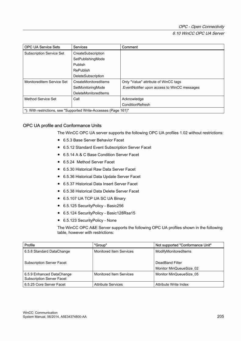
OPC UA Service Sets Services CommentSubscription Service Set CreateSubscription
SetPublishingModePublishRePublishDeleteSubscription
MonitoredItem Service Set CreateMonitoredItemsSetMonitoringModeDeleteMonitoredItems
Only "Value" attribute of WinCC tags.EventNotifier upon access to WinCC messages
Method Service Set Call AcknowledgeConditionRefresh
*): With restrictions, see "Supported Write-Accesses (Page 161)"
OPC UA profile and Conformance Units The WinCC OPC UA server supports the following OPC UA profiles 1.02 without restrictions:
● 6.5.3 Base Server Behavior Facet
● 6.5.12 Standard Event Subscription Server Facet
● 6.5.14 A & C Base Condition Server Facet
● 6.5.24 Method Server Facet
● 6.5.30 Historical Raw Data Server Facet
● 6.5.36 Historical Data Update Server Facet
● 6.5.37 Historical Data Insert Server Facet
● 6.5.38 Historical Data Delete Server Facet
● 6.5.107 UA TCP UA SC UA Binary
● 6.5.125 SecurityPolicy - Basic256
● 6.5.124 SecurityPolicy - Basic128Rsa15
● 6.5.123 SecurityPolicy - None
The WinCC OPC A&E Server supports the following OPC UA profiles shown in the following table, however with restrictions:
Profile "Group" Not supported "Conformance Unit"6.5.8 Standard DataChange Subscription Server Facet
Monitored Item Services ModifyMonitoredItems DeadBand FilterMonitor MinQueueSize_02
6.5.9 Enhanced DataChange Subscription Server Facet
Monitored Item Services Monitor MinQueueSize_05
6.5.25 Core Server Facet Attribute Services Attribute Write Index
OPC - Open Connectivity6.10 WinCC OPC UA Server
WinCC: CommunicationSystem Manual, 06/2014, A5E34374800-AA 205

Profile "Group" Not supported "Conformance Unit"6.5.26 Data Access Server Facet Data Access Data Access Analog
Data Access MultistateData Access PercentDeadBandData Access Semantic ChangesData Access Two State
6.5.35 Standard UA Server Attribute Services Attribute Write StatusCode & TimeStamp6.5.47 Standard UA Server Profile Attribute Services Attribute Write StatusCode & Timestamp
6.10.5 Name area of the WinCC OPC UA server
IntroductionThe WinCC OPC UA server provides OPC UA clients with a hierarchical name area and access to the following runtime data:
● Process values (WinCC tags and WinCC tag groups)
● Data log inclusive logging tags
● WinCC messages
The name area of the WinCC OPC UA server is attached in the "Objects" default folder.
The following screen shows the name area of the WinCC OPC UA server of an active WinCC project on the local PC ("@LOCALMACHINE::"):
OPC - Open Connectivity6.10 WinCC OPC UA Server
WinCC: Communication206 System Manual, 06/2014, A5E34374800-AA
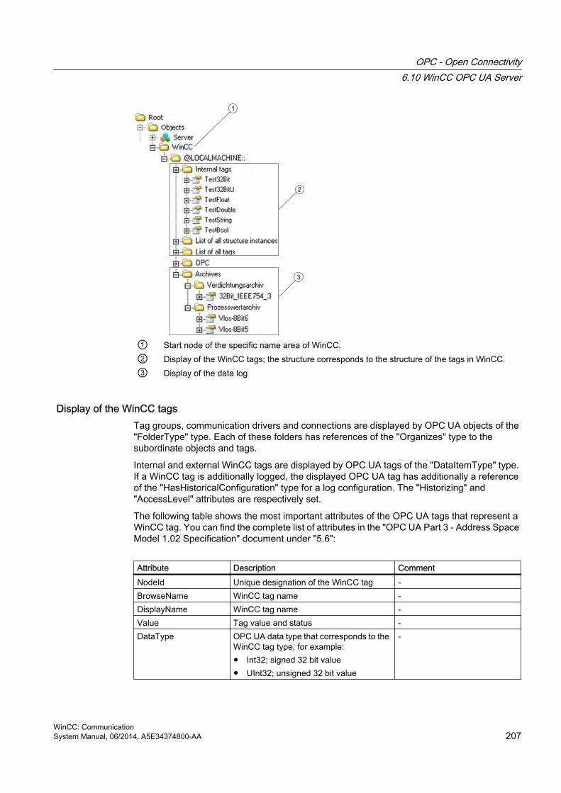
1
2
3
① Start node of the specific name area of WinCC. ② Display of the WinCC tags; the structure corresponds to the structure of the tags in WinCC. ③ Display of the data log
Display of the WinCC tags Tag groups, communication drivers and connections are displayed by OPC UA objects of the "FolderType" type. Each of these folders has references of the "Organizes" type to the subordinate objects and tags.
Internal and external WinCC tags are displayed by OPC UA tags of the "DataItemType" type. If a WinCC tag is additionally logged, the displayed OPC UA tag has additionally a reference of the "HasHistoricalConfiguration" type for a log configuration. The "Historizing" and "AccessLevel" attributes are respectively set.
The following table shows the most important attributes of the OPC UA tags that represent a WinCC tag. You can find the complete list of attributes in the "OPC UA Part 3 - Address Space Model 1.02 Specification" document under "5.6":
Attribute Description CommentNodeId Unique designation of the WinCC tag -BrowseName WinCC tag name -DisplayName WinCC tag name -Value Tag value and status -DataType OPC UA data type that corresponds to the
WinCC tag type, for example:● Int32; signed 32 bit value● UInt32; unsigned 32 bit value
-
OPC - Open Connectivity6.10 WinCC OPC UA Server
WinCC: CommunicationSystem Manual, 06/2014, A5E34374800-AA 207

Attribute Description CommentAccessLevel "CurrentRead" / "CurrentWrite"
"HistoryRead" / "HistoryWrite" correspondingly to the WinCC tag configuration
ValueRank Always "Scalar" -
Display of the logging tags Process values and compressed logs are displayed by OPC UA objects of the "FolderType" type. Each of these folders has references of the "Organizes" type to the related logging tags.
Logging tags from process value or compressed logs are displayed by OPC UA tags of the "BaseDateVariableType" type. A logging tag always has a reference of the "HasHistoricalConfiguration" type for a log configuration.
The following table shows the most important attributes of the OPC UA tags that represent a WinCC logging tag. You can find the complete list of attributes in the "OPC UA Part 3 - Address Space Model 1.01 Specification" document under "5.6":
Attribute Description CommentNodeId Unique designation of a logging tag -BrowseName Name of the archive tag -DisplayName Name of the archive tag -Description Node description -Value Not available For a logging tag, this attribute
cannot be read nor changed. DataType OPC UA data type that corresponds to the
WinCC tag type, for example:● Double; 64-bit floating point number● UInt32; unsigned 32 bit value
-
AccessLevel "HistoryRead" / "HistoryWrite" -ValueRank Always "Scalar" -
Access to WinCC messagesThe start node of the WinCC name area is an Event Notifier which allows the OPC UA clients to receive status changes for WinCC messages in runtime via Subscriptions .
6.10.6 OPC UA Data AccessInternal and external WinCC tags are displayed by OPC UA tags of the "DataItemType" type. Other DataAccess tag types as "AnalogItem" or "DiscreteType" are not supported.
The WinCC OPC A&E Server supports the reading access on the OPC UA tag attributes as "DataType" or "AccessLevel". Writing access and subscriptions are only supported for the "Value" attribute.
OPC - Open Connectivity6.10 WinCC OPC UA Server
WinCC: Communication208 System Manual, 06/2014, A5E34374800-AA

6.10.7 OPC UA Log Access
Introduction "OPC Historical Access" enables access to archives and includes the "Historical Data" and "Historical Events" services. The WinCC OPC UA server supports only the "Historical Data" service.
The WinCC OPC UA Server offers the OPC clients access to the raw data of tag archives via "Services".
● HistoryRead (READRAW)
● HistoryUpdate (INSERTDATA, REPLACEDATA, UPDATEDATA, DELETE_RAW)
You can read and limitedly write with an OPC UA client the values of archive tags in the tag archives. Depending on the configuration of the tag archive, the archive tag can contain either raw data or already processed process values.
Characteristics of archive tagsA process tag in WinCC can be located in multiple tag archives. In this case the process tag is linked to one of the corresponding archive tags.
Properties / Properties of archive configurationsThe following table shows the Properties of an OPC UA tag configuration of the "HistoricalConfigurationType" type: In the "Description" property, the archive tag comment configured in WinCC is displayed. You can find the complete list of properties in the "OPC UA Part 11 - Historical Access 1.02 Specification" document under "5.2.2":
Property Description / Value CommentDefinition WinCC process tag name For a process value archiveStepped True -
The following optional Properties are not supported:
● MaxTimeInterval
● MinTimeInterval
● ExceptionDeviation
● ExceptionDeviationFormat
Limitations for Service "HistoryUpdate"You can use the Service "HistoryUpdate" only on process value archives.
The following table lists the functions supported by the WinCC OPC UA server: Which functions are supported depends on the configuration of the WinCC OPC UA server as well as the process value archive configuration. You will find additional information in the "OPC UA Part 11 - Historical Access 1.00 Specification" document under "§5.5":
OPC - Open Connectivity6.10 WinCC OPC UA Server
WinCC: CommunicationSystem Manual, 06/2014, A5E34374800-AA 209

Service Function DescriptionHistoryUpdate INSERTDATA Insert new archive values REPLACEDATA Replace existing archive values UPDATEDATA Replace of insert archive values DELETE_RAW Delete archive values
6.10.8 OPC UA alarm & conditions
IntroductionThe OPC UA server provides access to the messages of the WinCC message system as of WinCC 7.3.
The OPC UA server forwards WinCC message status changes to OPC UA clients with WinCC-Event-Notifications via Subscriptions and Monitored Event Items but does not maintain a Condition instance in its name area. The Event Notifier node to be used is the start node of the WinCC name area. The UA client can filter the messages and define the list of message attributes returned.
The OPC UA server supports the "OPC UA Alarms & Conditions 1.02" specification.
The following section outlines the mapping of the WinCC message system to OPC UA. You can find additional information in the specification in "Part 9: Alarms and Conditions 1.02 Specification".
WinCC message system mapping to UA event typesWinCC messages are mapped to the following OPC UA event types:
WinCCEventTypeThis type is based on "BaseEventType" and maps "simple" WinCC messages with the following acknowledgment theory:
● "Message without status went out" is activated
● "Acknowledgment came in" is not activated
Examples of this type of message are starting and stopping motors.
WinCCAlarmConditionTypeThis type is based on "AlarmConditionType" and maps all messages which cannot be mapped on WinCCEventType, for example acknowledgeable messages and messages with the status "came in" and "went out".
The event for messages of the "WinCCAlarmConditionType" type is linked to a condition. For example, WinCC generates a message as soon as a tag limit is violated. This message in OPC UA is equivalent to an Alarm Condition.
OPC - Open Connectivity6.10 WinCC OPC UA Server
WinCC: Communication210 System Manual, 06/2014, A5E34374800-AA

WinCC message attributesThe two Event types add WinCC-specific message attributes to the basic type. The attributes are mapped 1:1 as UA Event Properties and are described in more detail in "Attributes of the WinCC message system".
Message class and message typeThe WinCC message system informs the user of disturbances and operating conditions in the process. A WinCC message always belongs to a specific message class and message type, which are specified in the "CLASSID", "TYPEID", "CLASSNAME" and "TYPENAME" attributes of the corresponding UA Events.
PriorityWhen configuring messages in the WinCC message system, you can configure a priority of between "0" and "16". The OPC UA specification defines a value range of "1" to "1000" for the Severity. "1" stands for the lowest and "1000" for the highest Severity.
The values of the priority must therefore be suitably mapped to the OPC severity. In standard mapping, a priority of "0" is assigned to OPC-Severity "1" and a priority of "16" to OPC-Severity "1000". All other values are interpolated linearly between "0" and "1000".
OPC UA mapping rulesDuring the configuration of the WinCC message system, settings are made to determine which process events generate a message. This message is generally shown as an Event in OPC UA.
The following table shows the most important Properties of an Events and how the WinCC message system provides the information.
OPC UA property Mapping in the WinCC message systemFor all event types: EventID Unique message designationEventType Event type: Node ID of the WinCCAlarmConditionType node
or WinCCEventType nodeSourceNode IrrelevantSourceName Indicates the source of the message. Mapping is described
in more detail below.Message Message text for the corresponding message number.Time Time of the event. The time stamp is given in UTCSeverity Priority of the WinCC message Only with WinCCAlarmConditionType: ConditionName Set text that is output as well as the message. The text output
depends on the mapping rule set:● "Mode 1" and "Mode 2": Message number● "Mode 3": Message class, for example "Process control
message"
OPC - Open Connectivity6.10 WinCC OPC UA Server
WinCC: CommunicationSystem Manual, 06/2014, A5E34374800-AA 211

OPC UA property Mapping in the WinCC message systemQuality Returns the quality of the messageConditionClassId Node ID of the "ProcessConditionClassType" nodeConditionClassName "ProcessConditionClassType"Retain "TRUE" with pending messagesNodeId ConditionId: unique designation for a UA-Condition, for
example an alarm. Required for acknowledgment, even if no Condition instances are supported
EnabledState "TRUE" is the message has been enabledActiveState/Id "TRUE" is the message has come inAckedState/Id "TRUE" is the message has been acknowledgedClientUserId Indicates the user that is logged on
Note
The following OPC UA Condition and Alarm Properties are not supported by the OPC UA server:● BranchId● LastSeverity● InputNode● ConfirmedState● SuppressedState● ShelvingState● SuppressedOrShelved● MaxTimeShelved
Message statuses / acknowledgment statusesThe following table shows WinCC message status mapping to the corresponding WinCCAlarmConditionType - Properties:
Message status EnabledState/Id ActiveState/Id AckedState/IdLocked message FALSE - -Enabled message TRUE Received message TRUE TRUE FALSESent message with acknowledgment
TRUE FALSE TRUE
Sent message without acknowledgment
TRUE FALSE FALSE
Acknowledged messages (message pending)
TRUE TRUE TRUE
Acknowledged messages (message no longer pending)
TRUE FALSE TRUE
Received, acknowledged message
TRUE TRUE TRUE
OPC - Open Connectivity6.10 WinCC OPC UA Server
WinCC: Communication212 System Manual, 06/2014, A5E34374800-AA

Message status EnabledState/Id ActiveState/Id AckedState/IdReceived, sent message with acknowledgment
TRUE FALSE TRUE
Received, sent message without acknowledgment
TRUE FALSE FALSE
Message acknowledged by the system (message pending)
TRUE TRUE TRUE
Message acknowledged by the system (message no longer pending)
TRUE FALSE TRUE
Emergency-acknowledged message (message pending)
TRUE TRUE TRUE
Emergency-acknowledged message (message no longer pending)
TRUE FALSE TRUE
Settings for mapping the WinCC message systemThe configuration of the OPC UA server also applies to the OPC UA server as regards the mapping of the Properties "SourceName" and "Message" of a message.
● With OPC A&E server with hierarchical access:
SourceName Indicates the source of a message. The Source has the format "<Server prefix>::Area\UserTextBlock 2". The server prefix of the local computer is "@LOCALMACHINE".
Message Returns the message text of the corresponding message number
● With OPC A&E server without hierarchical access:
SourceName Indicates the source of a message. The Source has the format "<Server prefix>::localhost::". The server prefix of the local computer is "@LOCALMACHINE".
Message Returns the message text of the corresponding message number
Alarm groupsIn WinCC 7.3, the WinCC alarm groups are not displayed in the name area.
Supported event methods
AcknowledgmentA WinCC message is acknowledged using the "Acknowledge" method of the "AcknowledgeableConditionType" node in the standard OPC UA info model.
Only messages of the "WinCCAlarmConditionType" type can be acknowledged.
ConditionRefreshMessages still pending are established using the "ConditionRefresh" method of the "ConditionType" node in the standard OPC UA info model.
OPC - Open Connectivity6.10 WinCC OPC UA Server
WinCC: CommunicationSystem Manual, 06/2014, A5E34374800-AA 213

FiltersThe OPC UA client can defined a filter for Monitored Event Items .
The following operators are, however, not supported by the OPC UA server:
● FilterOperator_Cast
● FilterOperator_BitwiseAnd
● FilterOperator_BitwiseOr
● FilterOperator_RelatedTo
● FilterOperator_InView
See alsoAttributes of the WinCC message system (Page 214)
6.10.9 Attributes of the WinCC message system
OverviewThe following table lists the configurable attributes of the WinCC message system. The attributes are mapped 1:1 as UA Event Properties .
WinCC message attribute Meaning Data typeCLASSNAME Name of message class StringTYPENAME Name of message type StringFORECOLOR Foreground color for incoming, outgoing and
acknowledged messages.Int32
BACKCOLOR Background color for incoming, outgoing and acknowledged messages.
Int32
FLASHCOLOR Flash color Int32FLAGS Indicates mandatory message acknowledgment Int32TEXT01…TEXT10 Content of user text block #1....#10 StringPROCESSVALUE01…PROCESSVALUE10 Content of process value block #1....#10 STATETEXT Status message StringINFOTEXT Information text for the message StringLOOPINALARM Indicates whether LoopInAlarm was configured Int32CLASSID Message class ID Int32TYPEID Message type ID Int32MODIFYSTATE Value of message status tag Int32AGNR Outputs the number of the automation system that
generated the messageInt16
OPC - Open Connectivity6.10 WinCC OPC UA Server
WinCC: Communication214 System Manual, 06/2014, A5E34374800-AA

WinCC message attribute Meaning Data typeCPUNR Outputs the number of the CPU that generated the
messageInt16
DURATION Outputs the time period between the incoming state, outgoing state and acknowledgment of a message
Int32
COUNTER Number of messages after the start of runtime Int32QUITSTATETEXT Indicates whether the message has been
acknowledgedString
QUITCOUNT Number of open, unacknowledged messages Int32PARAMETER Configuration parameter of the message Int32BLOCKINFO Current content of the message block StringALARMCOUNT Number of pending messages Int32LOCKCOUNT Number of locked messages Int32PRIORITY Priority of the message Int32APPLICATION Outputs the application which triggered the
messageString
COMPUTER Outputs the name of the computer which processed the message
String
USER Outputs the name of the user who processed the message
String
COMMENT Message comment StringHIDDEN-COUNT Number of hidden messages Int32OS-HIDDEN Indicates that the message is hidden BooleanOS_EVENTID WinCC message number Int32BIG_COUNTER Message counter Int64
See alsoOPC UA alarm & conditions (Page 210)
6.10.10 Configuring the WinCC OPC UA server
6.10.10.1 Configuration file
IntroductionThe WinCC OPC UA server is configured using the configuration file "OPCUAServerWinCC.xml". This chapter describes the layout of the configuration file. The chapter "How to configure the OPC UA server (Page 217)" describes how you configure the WinCC OPC UA server.
OPC - Open Connectivity6.10 WinCC OPC UA Server
WinCC: CommunicationSystem Manual, 06/2014, A5E34374800-AA 215

File locationThe project-specific configuration file "OPCUAServerWinCC.xml" is stored in the WinCC project folder under:
"<WinCC project folder>\OPC\UAServer"
LayoutThe configuration file is broken down into multiple sections.
Section <Secured Application>In this section, the OPC UA application security is set in compliance with OPC UA Specification / Part 6 / § "Security Settings Management".
<Secured Application> <BaseAddresses> <...></...> </BaseAddresses>.
Configuration of the URL of the WinCC OPC UA server.For additional information about the URL, refer to "Security concept of OPC UA (Page 198)".
<SecurityProfileUris> <SecurityProfile> <...></...> </SecurityProfile> ... </SecurityProfileUris>
Configuration of the supported security policiesUse the "none" setting only for test and diagnostics purposesFor more information about security policies, refer to "Security concept of OPC UA (Page 198)".
<ApplicationCertificate> <TrustedCertificateStore> <TrustedCertificates> <...>
Revision of the default certificate configuration according to OPC UA Specification / Part 6.(optional)
</Secured Application>
Section <Server Configuration>In this section you can set further server-specific parameters.
<Server Configuration> <SecurityPolicies> <SecurityPolicy> <...></...> </SecurityPolicy> ... </SecurityPolicies>
Configuration of the message security modes. Use the "none" setting only for test and diagnostics purposesFor more information about message security modes, refer to "Security concept of OPC UA (Page 198)".
<UserTokenPolicies> <UserTokenPolicy> <...></...> </UserTokenPolicy> ... </UserTokenPolicies>
Configuration of user identificationUse the "Anonymous" setting only for test and diagnostics purposesFor more information about message security modes, refer to "Security concept of OPC UA (Page 198)".
OPC - Open Connectivity6.10 WinCC OPC UA Server
WinCC: Communication216 System Manual, 06/2014, A5E34374800-AA

<FastInsert> <Users> <...></...> </Users> <Clients> <...></...> <Clients> </FastInsert>
Configuration of the optimized WinCC archive write access
<Server Configuration
6.10.10.2 How to configure the OPC UA server
RequirementA WinCC project·has been created.
Opening the configuration file 1. Open Windows Explorer.·Navigate to the directory "<WinCC project folder>OPC
\UAServer".
2. Open the "OPCUAServerWinCC.xml" configuration file. For more information, refer to "Configuration file (Page 215)"
OPC - Open Connectivity6.10 WinCC OPC UA Server
WinCC: CommunicationSystem Manual, 06/2014, A5E34374800-AA 217

Changing the port number of the WinCC OPC UA server1. If necessary, change the port number 4862 under <BaseAdresses>.
Do not use a port number that is already assigned to another application. The parameter [HostName] is the placeholder for the computer name and is determined during runtime. Example:<BaseAdresses><ua:String>opc.tcp://[HostName]:5210</ua:String><BaseAdresses>
Specifying security settings 1. Specify the security settings for communication.·For additional information, refer to
"Security concept of OPC UA (Page 198)"
2. Under <SecurityProfileUris>, you configure the supported "Security Policies".
– Enable the setting with "true".
– Disable the setting with "false".Example:<SecurityProfile> <ProfileUri>http://opcfoundation.org/UA/SecurityPolicy#None</ProfileUri> <Enabled>false</Enabled></SecurityProfile>
3. Under <SecurityPolicies>, you configure the associated "Message·security·modes". To deactivate a setting, delete the entire entry <SecurityPolicy>... </Security Policy>.Example:<SecurityPolicy> <ProfileUri>http://opcfoundation.org/UA/SecurityPolicy#None</ProfileUri> <MessageSecurityModes>None</MessageSecurityModes></SecurityPolicy>
NoteUnsecured communication between client and server
Use the "none" setting only for test and diagnostics purposes.
For secure client/server communication·in production mode, you need to use at least the following settings:● SecurityPolicy:·Basic128Rsa15
Message·Security·Mode:·Sign
OPC - Open Connectivity6.10 WinCC OPC UA Server
WinCC: Communication218 System Manual, 06/2014, A5E34374800-AA

Specifying user identification1. Specify the user identification for setting up the connection under
<UserTokenPolicies>. For more information, refer to "Security concept of OPC UA (Page 198)"To deactivate a setting, delete the entire entry.Example<UserTokenPolicy><TokenType>Anonymous</TokenType></UserTokenPolicy>
Configuring optimized WinCC archive write access1. If necessary, configure optimized WinCC archive write access under <FastInsert>.
– Set "true" to activate the optimized write access to WinCC archives for all OPC UA clients.
– Set "false" to set optimized WinCC archive write access for specific Windows users or OPC UA clients.You specify the Windows users under <Users>. You specify the OPC UA clients under <Clients>. Use the "Common Name" that is entered in the client certificate as ClientName. Example:<EnabledByDefault>false</EnabledByDefault><Users> <User>domain\user1</User></Users><Clients> <Client>ClientName1</Client></Clients>
OPC - Open Connectivity6.10 WinCC OPC UA Server
WinCC: CommunicationSystem Manual, 06/2014, A5E34374800-AA 219

6.11 Trace
IntroductionThe "Trace" function can be used to log tag values and function calls for purposes of testing and error analysis.
The entries are stored in a trace file. The trace shows the step-by-step progress of the establishment of the connection, thus making it easier to identify the source of a connection problem.
SettingsTrace output must be set in the registry of the operating system. For more information, refer to the SIMATIC Customer Support.
OPC - Open Connectivity6.11 Trace
WinCC: Communication220 System Manual, 06/2014, A5E34374800-AA

PROFIBUS FMS 77.1 WinCC channel "PROFIBUS FMS"
IntroductionThe "PROFIBUS FMS" communication driver makes the connection between a WinCC station and automation systems such as S5 or S7.
This chapter describes
● how to configure data transfer with the "PROFIBUS FMS" channel
● how to configure a connection and a tag.
Channel UnitThe communication driver has a channel unit. This provides the following capability:
● Channel unit PROFIBUS FMS for SIMATIC NET PROFIBUS (communication module DP 5613).
Note
The configuration of the logical connection can take place in configuration mode as well as in runtime. Both methods are explained.
Only WinCC can request data from the connected AS with the "PROFIBUS FMS" channel. Sending from the AS is not possible.
WinCC: CommunicationSystem Manual, 06/2014, A5E34374800-AA 221

7.2 Data type of the tags
IntroductionDefine the required tags for a logical connection. From the WinCC viewpoint, you can access the following data types:
● Binary tag
● Unsigned 8-bit value
● Signed 8-bit value
● Unsigned 16-bit value
● Signed 16-bit value
● Unsigned 32-bit value
● Signed 32-bit value
● Floating-point number 32-bit IEEE 754
● Text tag, 8-bit character set.
● Raw data type
PROFIBUS FMS7.2 Data type of the tags
WinCC: Communication222 System Manual, 06/2014, A5E34374800-AA

7.3 Configuring the Channel
7.3.1 Configuring a connection
7.3.1.1 Configuring a connection
IntroductionThe automation system must be connected to PROFIBUS with a suitable communication processor. The PROFIBUS FMS protocol must be supported by the hardware / software.
In automation systems S5-115U, S5-135U and S5-155U, communication processor CP 5431 FMS is used for instance.
in WinCC system, the communication module CP 5613 and software SIMATIC NET must be installed.
When configuring the connection, the following situations are handled differently:
● Configuring in configuration mode
● Configuring in Runtime
7.3.1.2 Configuring the connection in configuration mode
Procedure1. In the navigation area of the tag management, select the channel unit "PROFIBUS FMS"
in the tree of the communication driver "PROFIBUS FMS".
2. Select the entry "New Connection" in the shortcut menu of the channel unit.
3. Enter the name of the connection.
PROFIBUS FMS7.3 Configuring the Channel
WinCC: CommunicationSystem Manual, 06/2014, A5E34374800-AA 223

4. Select the entry "Connection parameters" from the shortcut menu of the connection.A dialog with the connection name as its title is displayed
5. Enter the name or the index of the logical connection in the "Name/Index" field.The Name/Index of the logical connection must be configured in the local communication relationship list (CRL).
6. If access authorization has been assigned for the logical connection, please select the "With Authorization" field.
PROFIBUS FMS7.3 Configuring the Channel
WinCC: Communication224 System Manual, 06/2014, A5E34374800-AA

7. The "Attributes" button opens the "Access Authorization" dialog:
8. Now you can enter the password for the logical connection. Close the dialog by clicking on the "OK" button.
9. Define the required parameter in the "Tag addressing" area. Close the dialog by clicking "OK".
Note
To configure the Name or Index of the connection, you must access the communication relationship list, which can be created with SIMATIC NCM PC or STEP 7.
PROFIBUS FMS7.3 Configuring the Channel
WinCC: CommunicationSystem Manual, 06/2014, A5E34374800-AA 225

7.3.1.3 How to configure the connection in Runtime
Procedure1. Select the connection and open the dialog window "Connection properties" in the shortcut
menu.
2. Click the "Properties" button. A dialog with the connection name as its title is displayed.
3. The configured connections from the communication relationship list (CRL) are shown in the "List of connections (communication relationship list)" area. Select whether the connection should be used with the respective index or name in the "Name/Index" field in the "Connection" area.
4. If access authorization has been assigned for the logical connection, please select the "With Authorization" field.
PROFIBUS FMS7.3 Configuring the Channel
WinCC: Communication226 System Manual, 06/2014, A5E34374800-AA
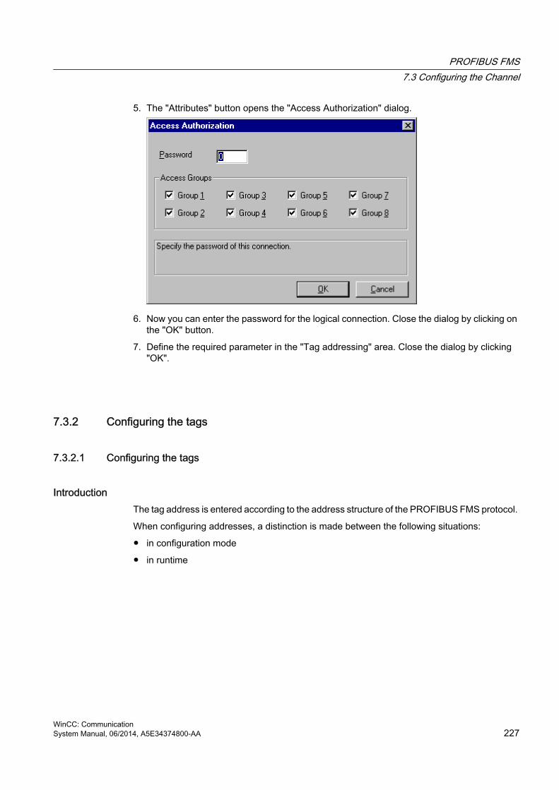
5. The "Attributes" button opens the "Access Authorization" dialog.
6. Now you can enter the password for the logical connection. Close the dialog by clicking on the "OK" button.
7. Define the required parameter in the "Tag addressing" area. Close the dialog by clicking "OK".
7.3.2 Configuring the tags
7.3.2.1 Configuring the tags
IntroductionThe tag address is entered according to the address structure of the PROFIBUS FMS protocol.
When configuring addresses, a distinction is made between the following situations:
● in configuration mode
● in runtime
PROFIBUS FMS7.3 Configuring the Channel
WinCC: CommunicationSystem Manual, 06/2014, A5E34374800-AA 227

7.3.2.2 Configuring the address of the tags in configuration mode
Procedure1. Select the required data type for the tags (e.g. signed 16-bit value) in the field "Data type".
2. Open the "Properties" dialog.For this purpose, click in the "Address" field and then on the button.
3. Enter the name or index of the tag from the remote automation system in the "Name/Index" field.
4. If the tag is a structured tag (structure or array), you must also enter - in the field "Subindex" - which part of the tag (structure component or array element) should be read or written.
Note
The name or index and the Subindex must match the name or index in the Object List for the logical connection of the external automation system. Otherwise it will not be possible to access the tag in Runtime.
PROFIBUS FMS7.3 Configuring the Channel
WinCC: Communication228 System Manual, 06/2014, A5E34374800-AA

7.3.2.3 How to configure the address of the tags in runtime
Procedure1. Select the required data type for the tags (e.g. signed 16-bit value) in the field "Data type".
2. Open the "Properties" dialog.For this purpose, click in the "Address" field and then on the button.
3. The tags that can be accessed through the selected connection are listed in the "List of Remote Tags" area. Select whether the tag should be chosen using its index or its name in the "Remote tag" area.
4. In the "List of the Remote Tags", double click on the desired tag to select it.
5. The selected tag will be displayed in the "Name/Index" field in the "Remote Tag" area.
6. If the tag is a structured tag (structure or array), you must also enter - in the field "Subindex" - which part of the tag (structure component or array element) should be read or written.
PROFIBUS FMS7.3 Configuring the Channel
WinCC: CommunicationSystem Manual, 06/2014, A5E34374800-AA 229


S5 Ethernet Layer 4 88.1 WinCC Channel "SIMATIC S5 Ethernet Layer 4"
IntroductionThe communication driver is used e.g. to connect automation systems SIMATIC S5-115U/H, SIMATIC S5-135U and SIMATIC S5-155U/H with the ISO transport protocol or the TCP/IP protocol.
Depending on the communication protocol that is used, the following communication partners will be used.
Communication protocol WinCC side SIMATIC S5 sideISO transport protocol CP1612 (3Com-compatible)
CP1613CP1623
CP1430 TF
TCP/IP (conforming with RFC1006) CP1612 (3Com-compatible)CP1613 CP1623
CP1430 TCP
When using this channel, no local database is required.
Channel unitsThe communication driver has two channel units "CP1413-x" which can operate a maximum of two CP 1612, CP1613 or CP1623. The functionality of the channel unit is identical. They differ only in the logical device names of the two CPs. CP1623 is identical to CP1613, but is operated via PCI Express.
Communication can be established via the TCP/IP protocol with a CP1612, CP1613 or CP1623 using the third channel unit "TCP/IP".
The logical device name can be changed in the system parameters of a channel unit. Here, it is also possible to set the parameters for the protocol used.
The following application capabilities exist:
● Channel unit "S5-Transport (CP 1413-1)" for the communication modules for SIMATIC Industrial Ethernet (CP 1612/1613/1623).
● Channel unit "S5-Transport (CP 1413-2)" for the communication modules for SIMATIC Industrial Ethernet (CP 1612/1613/1623).
● Channel unit "S5-Transport (TCP/IP)" for the communication modules for SIMATIC Industrial Ethernet (CP 1612/1613/1623).
WinCC: CommunicationSystem Manual, 06/2014, A5E34374800-AA 231

8.2 Data type of the tags
IntroductionDefine the required tags for a logical connection. From the WinCC viewpoint, you can access the following data types:
● Binary tag
● Unsigned 8-bit value
● Signed 8-bit value
● Unsigned 16-bit value
● Signed 16-bit value
● Unsigned 32-bit value
● Signed 32-bit value
● Floating-point number 32-bit IEEE 754
● Text tag, 8-bit character set
● Raw data type
S5 Ethernet Layer 48.2 Data type of the tags
WinCC: Communication232 System Manual, 06/2014, A5E34374800-AA

8.3 Configuring the Channel
8.3.1 Configuring the channel "SIMATIC S5 Ethernet Layer 4"
IntroductionThe following steps are required for configuring the channel "SIMATIC S5 Ethernet Layer 4".
1. Configuring the connection
2. Configuring the tags
3. System parameter configuration
8.3.2 How to configure the connection
IntroductionThe connection parameters are almost identical for all protocols used. In the following example, communication is described using the ISO transport protocol with a channel unit "CP1413-x".
When implementing the TCP/IP protocol, the IP address of the AS is entered instead of the Ethernet address. The IP address consists of four numerical values, separated by dots. The numerical values must be within the range of 0-255.
For a logical connection, WinCC establishes one connection in the transport layer for reading ("READ function" area) and one for writing ("WRITE function" area). The address parameters for both functions are defined in the dialog. Only if both connections are established is the logical connection also indicated as being "established".
Allocations for the READ function
WinCC side SIMATIC S5 sideFETCH-Active(Request "READ-Active")
READ-Passive(Request "READ-Passive")
FETCH-Passive(Request "WRITE-Passive")
WRITE-Active(Request "WRITE-Active")
S5 Ethernet Layer 48.3 Configuring the Channel
WinCC: CommunicationSystem Manual, 06/2014, A5E34374800-AA 233

Note
It is not possible to write binary or byte variables in the data area of the AS, if the data from the AS is sent active, i.e. the READ function is set to "FETCH Passive" in the connections parameters.
A FETCH Passive connections is only assigned the "OK" status if at least one telegram has been sent from AS to WinCC.
Allocations for the WRITE function
WinCC side SIMATIC S5 sideRequest "WRITE Active" Request "WRITE Passive"
Procedure1. Select the entry "Connection parameters" from the shortcut menu of the connection.
The "Connection properties" dialog opens.
2. Enter the station address of the SIMATIC S5 on the industrial Ethernet bus in the field "Ethernet Address AG". When the TCP/IP protocol is being implemented, the IP address is entered here in the IP address AG" field.
S5 Ethernet Layer 48.3 Configuring the Channel
WinCC: Communication234 System Manual, 06/2014, A5E34374800-AA

3. Define the parameters for the READ function in the WinCC system. These are independent of the request used in the SIMATIC S5.
4. Then, enter the value in the allocated field "Own TSAP" that was configured in the "Remote parameter" as "TSAP" while configuring the CP1430 TF.
5. Now, enter the value in the allocated field "Remote TSAP" that was configured in the "Local parameter" as "TSAP" while configuring the CP1430 TF.
6. Define the parameters "Own TSAP" and "Remote TSAP" for the WRITE function accordingly.
Note
In the entries for "TSAP", you must not use any spaces.
8.3.3 Configuring the tags
8.3.3.1 Configuring the tags
IntroductionFor a connection between WinCC and the AS via channel "SIMATIC S5 Ethernet Layer 4", tags of different data types can be created in WinCC. The following describes how to configure a tag of these data types.
● Addresses of tags
● Configuring a tag with bit by bit access
● Configuring a tag with byte by byte access
● Configuring a tag with word by word access
● Configuring a raw data tag
8.3.3.2 Addresses of tags
IntroductionThe tag address is entered according to the address structure of the SIMATIC S5.
Depending on the tag type, the access to memory areas in the AS is bit by bit, byte by byte or word by word. For this purpose, the addressed memory area is read from the AS for every
S5 Ethernet Layer 48.3 Configuring the Channel
WinCC: CommunicationSystem Manual, 06/2014, A5E34374800-AA 235

single write request and the corresponding bits and/or bytes are modified. Afterwards, the data is written back to the AS's memory.
Note
Changes that have been made by the AS in a read data area are overwritten when writing back into the data area.
It is not possible to write binary or byte variables in the data area of the AS, if the data from the AS is sent active, i.e. the READ function is set to "FETCH Passive" in the connections parameters.
Configuring the address of a tag is done independent of the tag type:
● With tags of type "binary" or 8 bit value", first the "Bits-/Bytes-tag" dialog is opened, in which the bitwise or byte-wise access to the memory area of the AS is defined. Afterwards, the address of the tag in the AS memory is defined in the "Address properties" dialog.
● For word-oriented tags, the address of the tag in the AS memory is defined in the "Address properties" dialog. The dialog "Bits-/Bytes-tag" is not opened, since the access to the AS memory is word by word.
S5 Ethernet Layer 48.3 Configuring the Channel
WinCC: Communication236 System Manual, 06/2014, A5E34374800-AA

8.3.3.3 How to Configure a Tag with Bit by Bit Access
Procedure1. Select the connection and open the dialog window "Bit/Byte tag" in the shortcut menu.
For this purpose, click in the "Address" field and then on the button.
2. Click the "Select" button. The "Bit/Byte tag" dialog is opened.
3. Use the check box to define whether access should be enabled for reading and writing certain bits in the memory area.
4. Select the addressing methods for the AS memory in the selection field e.g. "Word" or "Byte".
5. Select the number of bits to be changed in the selection field.
6. Use the "Selection" button to open the "Address properties" dialog for defining the tag address in AS.
S5 Ethernet Layer 48.3 Configuring the Channel
WinCC: CommunicationSystem Manual, 06/2014, A5E34374800-AA 237

Note
With the S5, flags, inputs and outputs can be addressed byte by byte; data blocks (DB, DX) are addressed word by word.
Activating the check box "Access a bit" affects the display of the fields of the "Address properties" dialog.
For word-oriented tags, the described "Bit-/Byte-tag" is not opened because the address of the tags and therefore the access to PLC memory is by word.
8.3.3.4 How to Configure a Tag with Byte by Byte Access
Procedure1. Select the tag and select the data type "Unsigned 8-bit value" or "Signed 8-bit value" in the
"Data type" field.
2. Select the connection and open the dialog window "Bit/Byte tag" in the shortcut menu.For this purpose, click in the "Address" field and then on the button.
3. Click the "Select" button. The "Bit/Byte tag" dialog is opened.
4. Use the check box to define whether access should be enabled for reading and writing certain bytes in the memory area.
S5 Ethernet Layer 48.3 Configuring the Channel
WinCC: Communication238 System Manual, 06/2014, A5E34374800-AA

5. Only "Word" is shown as the AS memory addressing type in the selection field.
6. Select the number of bytes to be changed in the selection field.
7. Use the "Selection" button to open the "Address properties" dialog for defining the tag address in AS.
Note
With the S5, flags, inputs and outputs can be addressed byte by byte; data blocks (DB, DX) are addressed word by word.
Selecting the check box "Access a byte" affects the display of the fields of the "Address properties" dialog.
For word-oriented tags, the described "Bit-/Byte-tag" is not opened because the address of the tags and therefore the access to PLC memory is by word.
8.3.3.5 How to Configure a Tag with Word by Word Access
IntroductionThe addresses of tags in AS are defined with the dialog that is described here.
● With tags of type "binary" or 8 bit value", first the "Bits-/Bytes-tag" dialog is opened, in which the bitwise or byte-wise access to the memory area of the AS is defined.
● For word-oriented tags, the "Bit-/Byte-tag" dialog is not opened because the address of the tags and therefore the access to AS memory is by word.
S5 Ethernet Layer 48.3 Configuring the Channel
WinCC: CommunicationSystem Manual, 06/2014, A5E34374800-AA 239

Procedure1. Select the tag and select the required data type for the tags (e.g. signed 16-bit value) in
the field "Data type".
2. Open the "Address properties" dialog.For this purpose, click in the "Address" field and then on the button.
3. Choose whether the tag is located in a data block, the flag area, an input area or an output area in the "Data Area" field of the "Address" tab.
4. If the tag is in a data block, the "DB No." field is also shown. Here, you enter the number of the data block.
5. The type of addressing is entered in the "Addressing" field. Normally, you can use the default definition.
6. Enter the address in the respective field (e.g. "DW ").
Note
For tags of type "binary" or "8 bit value", displaying the fields of this dialog depends on the selection made for "Access to bits/bytes" in the "Bits-/Bytes-tag" dialog.
If the tag of a word-oriented data area is to be written, the start address must be in the left byte and the length of the tags must be an even number.
S5 Ethernet Layer 48.3 Configuring the Channel
WinCC: Communication240 System Manual, 06/2014, A5E34374800-AA

8.3.3.6 How to configure a raw data tag
IntroductionThe following is a description of how the address of a raw data tag is defined.
Note
If the tag of a word-oriented data area is to be written, the start address must be in the left byte and the length of the tags must be an even number.
Procedure1. Select the tag and select the entry "Raw data type" in the field "Data type".
2. Open the "Address properties" dialog.For this purpose, click in the "Address" field and then on the button.
3. Choose whether the tag is located in a data block, a flag, an input area or an output area in the "Data Area" field.
4. If the tag is in a data block, the "DB No." field is also shown. Here, you enter the number of the data block.
5. The type of addressing is entered in the "Addressing" field. Normally, the default definition can be used.
S5 Ethernet Layer 48.3 Configuring the Channel
WinCC: CommunicationSystem Manual, 06/2014, A5E34374800-AA 241

6. Enter the data address in the field underneath. The label on the field depends on the entry in the "Addressing" field, e.g. "DBW" for Word addressing.
7. Enter the length of the raw data block in bytes in the Length field.
8. Define which type of raw data tag is concerned in the "Raw data type" area.
8.3.4 System parameters
8.3.4.1 System parameters of the channel unit
IntroductionIf you require a configuration that deviates from the standard WinCC settings, you can make all the required changes using the "System Parameter" dialog of the channel unit.
The system parameters are almost identical for all protocols used. When implementing the TCP/IP protocol, only the device name given during the installation is different.
The following individual points can be changed:
● the device name
● the transport parameter
Note
The system parameters apply for all CPs in the AS.
Device NameCommunication between WinCC and the automation system takes place via logical device names. These names are assigned during the installation of the communication module and are unit-specific. The device name represents the logical device name. The logical device name is given the name "/CP_H1_1:/ SCP" with the ISO transport protocol and "/TCP_IP:/SCP" with the TCP/IP protocol as a default definition.
Note
When using the TCP/IP protocol, you must check whether the device name in WinCC matches the "Access point of the application" in the "Set PG/PC interface" dialog. The device name must also be changed in "Set PG/PC interface".
Transport ParameterSpecific settings for the channel unit are made in the transport parameters, e.g. PDU size, setup attempts, etc.
S5 Ethernet Layer 48.3 Configuring the Channel
WinCC: Communication242 System Manual, 06/2014, A5E34374800-AA

8.3.4.2 How to Change the Device Name
IntroductionParameters of the channel unit are set with the system parameters, e.g. the logical device name or the transport parameters.
The system parameters are almost identical for all protocols used.
In the following example, communication is described using the ISO transport protocol with a channel unit "CP1413-x".
When implementing the TCP/IP protocol, only the device name given during the installation is different.
Procedure1. Select the channel unit and open dialog window "System parameters" with the context
menu.
2. Select the "Device Name" Tab.
3. Now, you can select the device name shown in bold print with the mouse and change it with a mouse click in the name field for the device name.
S5 Ethernet Layer 48.3 Configuring the Channel
WinCC: CommunicationSystem Manual, 06/2014, A5E34374800-AA 243

Note
The device name is defined during the installation of the hardware driver. Only if you have defined another name there, which is not recommended, will you have to change the device name here as well.
8.3.4.3 How to change the transport parameter
Procedure1. Select the channel unit and open dialog window "System parameters" with the context
menu.
2. Select the "Transport parameter" tab.
3. Set the value for "PDU size" to the value that was configured on the communication module CP 1430.
4. Define how often a connection establishment should be attempted in the "Setup attempt" filed.
S5 Ethernet Layer 48.3 Configuring the Channel
WinCC: Communication244 System Manual, 06/2014, A5E34374800-AA

5. Select "Infinite" in the "Duration of Send Repetitions" area.
6. Enter value e.g. 30 in the "Acknowledgement time" field so that you are informed of the tag status after 30 seconds at the most, if the communication partner has not responded within this time (e.g. AS in "Stop" status).
S5 Ethernet Layer 48.3 Configuring the Channel
WinCC: CommunicationSystem Manual, 06/2014, A5E34374800-AA 245

8.4 Appendix
8.4.1 Appendix
IntroductionAdded information on the channel "SIMATIC S5 Ethernet Layer 4" is provided in the appendix.
8.4.2 Internal error codes and constants
8.4.2.1 Internal error codes and constants
IntroductionThe following tables contain the most important error codes and constants. The information is intended for "insiders". Therefore, we have not gone into more detail on the meanings of the codes and constants.
● Error codes during connection disturbances
● iNA960 messages
● SCI messages
8.4.2.2 Error codes during connection disturbances
IntroductionThe most important error codes are listed in this section. If an error with an error code that is not in the table occurs, please call the WinCC hotline.
Fehler_0002-INVALID_RQFaulty request block.
Fehler_0004-NO_RESOURCESNo resources free in CP.
Fehler_0006-UNKNOWN_REFERENCEIncorrect OPEN reference defined.
S5 Ethernet Layer 48.4 Appendix
WinCC: Communication246 System Manual, 06/2014, A5E34374800-AA

Fehler_0008-BUFFER_TOO_SHORTUser buffer too short.
Fehler_0010-BUFFER_TOO_LONGUser buffer too long.
Fehler_0012-ILLEGAL_REQIncorrect "negot_options" defined.
Fehler_0014-REM_ABORTConnection aborted by remote station.
Fehler_0016-LOC_TIMEOUTTimeout.
Fehler_0018-UNKNOWN_CONN_CLASSUnknown connection class.
Fehler_0020-DUP_REQConnection already established.
Fehler_0022-CONN_REJECTConnection request rejected by remote.
Fehler_0024-NEGOT_FAILEDConnection abort faulty "negot-option".
Fehler_0026-ILLEGAL_ADDRESSFaulty transport address.
Fehler_0028-NETWORK_ERRORBus or CP disrupted.
Fehler_0030-PROTOCOL_ERRProtocol error.
S5 Ethernet Layer 48.4 Appendix
WinCC: CommunicationSystem Manual, 06/2014, A5E34374800-AA 247

Fehler_0032-ILLEGAL_RB_LENGTHIncorrect request block length.
Fehler_0784-E_NO_HWNo communication hardware found.
● Communication module defective.
● Communication module not installed correctly.
● Wrong port address defined.
Fehler_0786-E_CNFDriver configured incorrectly or invalid parameter in the registry.
Fehler_0787-E_BAUDRATEIncorrect baudrate or incorrect interrupt vector defined.
Fehler_0788-E_HSAIncorrect HSA (Highest Station Address) defined.
Fehler_0789-E_TSThe defined local participant number (TS_ADR) is already assigned.
Fehler_0791-E_INT_NOT_PROVThe defined interrupt vector (IRQ) is not available on the communication module.
Fehler_0792-E_INT_BUSYThe defined interrupt vector (IRQ) is already occupied on the communication module.
Fehler_0800-E_NO_FILEThe selected communication driver cannot be loaded; the file was not found.
● Communication driver not installed correctly.
Fehler_0897-E_LOGDEVThe logical device is not defined in the registry.
● Communication driver not installed correctly.
● Entry damaged or deleted in the registry.
S5 Ethernet Layer 48.4 Appendix
WinCC: Communication248 System Manual, 06/2014, A5E34374800-AA

● Check the setting of the logical device name with the "Set PG/PC interface" program.
● Check the setting for the logical device name in the "System parameter - Device" mask.
Fehler_0898-E_L2DRIVERThe entry "L2DRIVER" is missing in the registry.
● Module error or module installed incorrectly.
Fehler_0900-E_L4DRIVERThe entry "L4DRIVER" is missing in the registry.
● Module error or module installed incorrectly.
Fehler_30000-EC_WATCHDOGWatchdog error.
Fehler_30001-EC_PDUERRORPDU not expected.
Fehler_30005-EC_ONLERRORFault loading the S7-Online-DLL.
8.4.2.3 iNA960 messages
General iNA960 messages
OK_RESP 1 0x01 Request executed with no errorsOK_EOM_RESP 3 0x03 Data block received with no errorsOK_DECIDE_REQ_RESP 5 0x05 Request executed with no errorsOK_CLOSED_RESP 7 0x07 Connection aborted by local user
iNA960 error messages
INVALID_REQ 2 0x02 Faulty request blockNO_RESOURCES 4 0x04 No resources free in CPUNKNOWN_REFERENCE 6 0x06 Incorrect OPEN reference definedBUFFER_TOO_SHORT 8 0x08 User buffer too shortBUFFER_TOO_LONG 10 0x0A User buffer too long
S5 Ethernet Layer 48.4 Appendix
WinCC: CommunicationSystem Manual, 06/2014, A5E34374800-AA 249

ILLEGAL_REQ 12 0x0C Incorrect "negot_options" definedREM_ABORT 14 0x0E Connection aborted by remote stationLOC_TIMEOUT 16 0x10 TimeoutUNKNOWN_CONN_CLASS 18 0x12 Unknown connection classDUP_REQ 20 0x14 Connection already establishedCONN_REJECT 22 0x16 Connection request rejected by remoteNEGOT_FAILED 24 0x18 Connection abort faulty negot-optionILLEGAL_ADDRESS 26 0x1A Faulty transport addressNETWORK_ERROR 28 0x1C Bus or CP disruptedPROTOCOL_ERR 30 0x1E Protocol errorILLEGAL_RB_LENGTH 32 0x20 Incorrect request block length
8.4.2.4 SCI messagesSee description in the "SINEC Communication Interface SCI" manual (A/5-15).
SCI messages
SCP_OK 0 0x00 No errorSCP_INCONS 201 0xC9 Minor device number is not 00SCP_RESOURCE 202 0xCA DPRAM request invalidSCP_CONFIG 203 0xCB Configuration error (NUM_PROCS)SCP_NOCONFIG 204 0xCC SCP driver not configuredSCP_PARAM 206 0xCE Incorrect modeSCP_DEVOPEN 207 0xCF Open already performedSCP_BOARD 208 0xD0 Board not inserted/recognizedSCP_SOFTWARE 209 0xD1 IRQ error or software not foundSCP_MEM 210 0xD2 Low memory in DPRAMSCP_MODE 211 0xD3 Download process not yet endedSCP_LOADER 212 0xD4 No response from loaderSCP_SIGNAL 213 0xD5 Process started asynchronouslySCP_NOMESS 215 0xD7 No message arrived for the processSCP_USERMEM 216 0xD8 length_of_buffer too smallSCP_WINDOW 217 0xD9 Too many SEND callsSCP_TIMEOUT 219 0xDB Timeout on SCPSCP_ATTACH 220 0xDC Reset not executed/Channel still activeSCP_ILLEGAL_REQUEST 221 0xDD Illegal requestSCP_ERECOVERF 223 0xDF Buffer not retrieved with scp_receive SCP_ECLOSED 224 0xE0 All buffers assigned for the connectionEUSERMAX 225 0xE1 SCP_EINTR 226 0xE2 SCP_BOARD_OPEN 231 0xE7
S5 Ethernet Layer 48.4 Appendix
WinCC: Communication250 System Manual, 06/2014, A5E34374800-AA

SCP_NO_WIN_SERV 233 0xE9 EPROTECT 234 0xEA License not found
SCI messages
SCP_DB_FILE_DOES_NOT_EXIST 240 0xF0SCP_DB_FILE_CLOSE_NOT_OK 241 0xF1SCP_SEND_NOT_SUCCESSFUL 242 0xF2SCP_RECEIVE_NOT_SUCCESSFUL 243 0xF3SCP_NO_DEVICE_AVAILABLE 244 0xF4SCP_ILLEGAL_SUBSYSTEM 245 0xF5SCP_ILLEGAL_OPCODE 246 0xF6SCP_BUFFER_TOO_SHORT 247 0xF7SCP_BUFFER_1_TOO_SHORT 248 0xF8SCP_ILLEGAL_PROTOCOL_SEQUENCE 249 0xF9SCP_ILLEGAL_PDU_ARRIVED 250 0xFASCP_REQUEST_ERROR 251 0xFBSCP_NO_LICENSE 252 0xFC
Additional online DLL messages on the SCP interface
E_TIMER_INIT 768 0x0300 WIN Set-timer request unsuccessfulE_INIT_COM 769 0x0301 E_NO_HW 784 0x0310 MPI module not foundE_HW_DEFEKT 785 0x0311 Problem with the hardwareE_CNF 786 0x0312 Incorrect configuration parameterE_BAUDRATE 787 0x0313 Incorrect baudrate/incorrect IntVectorE_HSA 788 0x0314 Incorrect HSA configuredE_TS 789 0x0315 Configured address already assignedE_OCC 790 0x0316 HW_Device already assignedE_INT_NOT_PROV 791 0x0317 Interrupt not availableE_INT_BUSY 792 0x0318 Interrupt occupiedE_SAP 793 0x0319 SAP deactivate: SAP not occupiedE_UNPLUGGED 794 0x031a No remote station foundE_SYNI 795 0x031b Syni Error occurredE_AMPRO 796 0x031c AMPRO 2 reported a system errorE_BUFFSIZE 797 0x031d No buffer of this size createdE_NO_FILE 800 0x0320 DLL/VxD File not found or entries in registry destroyed E_NO_ENTRY 801 0x0321 Address does not exist in DLLE_VERSION 816 0x0330 Version conflict between SMC driver and SMC firmwareE_COMCNF 817 0x0331 Problem with the COM port configurationE_NO_SMC 818 0x0332 SMC no longer responds
S5 Ethernet Layer 48.4 Appendix
WinCC: CommunicationSystem Manual, 06/2014, A5E34374800-AA 251

E_COMMBADID 819 0x0333 COM port is not configuredE_COMMOPEN 820 0x0334 COM port is not available E_SMCBUSY 821 0x0335 Serial driver is currently in use with another
configurationE_SMCMODEM 822 0x0336 No connection exists to a PC/MPI cableE_SMCNOLEG 823 0x0337 PC/MPI cable rejects request, necessary authorization
is missingE_ONLINE 896 0x0380 Internal error at the IOCTL interfaceE_LOGDEV 897 0x0381 Logical device not in registryE_L2DRIVER 898 0x0382 L2DRIVER entry is missing in the registryE_L4DRIVER 900 0x0384 L4DRIVER entry is missing in the registryE_SYSERROR 1023 0x03FF System error
Channel-specific error codes
EC_WATCHDOG 30000 0x7530 Watchdog errorEC_PDUERROR 30001 0x7531 PDU not expectedEC_ONLERROR 30005 0x7535 Fault loading the S7-Online-DLL
S5 Ethernet Layer 48.4 Appendix
WinCC: Communication252 System Manual, 06/2014, A5E34374800-AA

S5 PROFIBUS FDL 99.1 WinCC channel "SIMATIC S5 Profibus FDL"
IntroductionThe channel "SIMATIC S5 Profibus FDL" is used for communication between WinCC Station and a SIMATIC S5 automation system. The PROFIBUS (Process Field Bus) network type and protocol FDL (Field Data Link) are used in this case.
PROFIBUS is the network for small to medium sized data quantities. A broad spectrum of automation tasks can be completed with a maximum of 127 possible participants.
Reading/writing tags via PROFIBUS, using the FDL protocol, is done using request and response telegrams. The request telegram is sent to the automation device from WinCC. The AS answers with the response telegram.
An FDL connection is specified with the local and remote connection end point (Service Access Point).
This chapter describes
● how to configure the data transfer with the "SIMATIC S5 Profibus FDL" channel.
● how to create a sample project
Channel unit FDL (CP5412/A2-1)Independent of the communication processor used, CP 5613 or CP 5614, connection can be made to the SIMATIC S5 via the channel unit "FDL (CP5412/A2-1)". This channel unit supports
WinCC: CommunicationSystem Manual, 06/2014, A5E34374800-AA 253

up to a maximum of 24 connections. In order for the channel to function, a channel unit and a connection must be set up.
Service Access PointSAPs are local data interfaces within a PROFIBUS node. The SAPs must be configured in WinCC and on the AS. A unique identification is defined with the Service Access Point. This unique identification is required for communication between the WinCC and the AS.
Active connectionAn active connection is also called a Fetch connection. This is a connection, with which an active partner retrieves data with a communication partner. The communication partner that the data is retrieved from is designated as a passive partner.
Passive connectionA passive connection exists if the active AS sends data to the passive WinCC partner asynchronously without a request telegram.
S5 PROFIBUS FDL9.1 WinCC channel "SIMATIC S5 Profibus FDL"
WinCC: Communication254 System Manual, 06/2014, A5E34374800-AA

9.2 Supported data types and data ranges
IntroductionOnly certain data types and data ranges are supported for communication from SIMATIC S5 via PROFIBUS FDL.
Supported data types
WinCC Data type SIMATIC S5 data typeBinary tag BITSigned 8-bit value non-existent in the SIMATIC S5Unsigned 8-bit value BYTESigned 16-bit value WORDUnsigned 16-bit value WORDSigned 32-bit value DWORDUnsigned 32-bit value DWORDFloating-point number 32-bit IEEE 754 DWORDFloating-point number 64-bit IEEE 754 non-existent in the SIMATIC S5Text tag, 8-bit character set ARRAY OF BYTEText tag, 16-bit character set non-existent in the SIMATIC S5Raw data type ARRAY OF BYTE
Access to SIMATIC S5 tagsThe access to SIMATIC S5 tags is done word by word to data block DB or extended data blocks DX. This allows read and write access.
Access to a SIMATIC S5 tag of data type BITSIMATIC S5 tags of data type BIT only allow read access. This restriction applies for active or passive connections.
Access to a SIMATIC S5 tag of data type BYTESIMATIC S5 tags of data type BYTE only allow read access.
To configure a byte tag, the "left byte" or "right byte" of a 16 bit data word must be selected for addressing.
Access to a SIMATIC S5 tag of data type ARRAY OF BYTESIMATIC S5 tags of data type ARRAY OF BYTE only allow read access.
S5 PROFIBUS FDL9.2 Supported data types and data ranges
WinCC: CommunicationSystem Manual, 06/2014, A5E34374800-AA 255

9.3 Features of the WinCC channel "SIMATIC S5 Profibus FDL"
IntroductionThe capabilities of communication, from WinCC via the communication driver for PROFIBUS, are listed in the following section. All supported data types and the respective capabilities for format adaptation are also listed.
Note
Features for writing tags: When configuring in WinCC, make sure that every tag is transferred individually when writing more than one tag into data areas of the automation system.
This behavior is especially important when writing more than one tag to a script with function "SetTagMultiWait". Since this function is only executed at the end of a transfer of all the tags sent to it, noticeable waiting times can occur with a greater number of tags.
Check for whether the utilization of the "Wait" function is required for a larger amount of tags. In this case, the use of a raw data tag may also be a good idea, especially if the data is sequential in the AS data area.
Type conversionA format adaptation is then required if a certain value range or a conversion e.g. of decimal to BCD ("Unsigned 8 bit value" converted to "ByteToBCDWord") if necessary. No format adaptation is performed as standard procedure.
The following table lists the supported WinCC data types and the respective format adaptation capabilities.
WinCC Data type Type conversionBinary tag NoSigned 8-bit value non-existent in the S5Unsigned 8-bit value YesSigned 16-bit value YesUnsigned 16-bit value YesSigned 32-bit value YesUnsigned 32-bit value YesFloating-point number 32-bit IEEE 754 YesFloating-point number 64-bit IEEE 754 non-existent in the S5Text tag, 8-bit character set NoText tag, 16-bit character set non-existent in the S5Raw data type No
S5 PROFIBUS FDL9.3 Features of the WinCC channel "SIMATIC S5 Profibus FDL"
WinCC: Communication256 System Manual, 06/2014, A5E34374800-AA

WinCC sideThe communication driver SIMATIC S5 Profibus FDL supports the communication with the following communication processors:
Communications processor Bus typeCP5613 PCICP5614 PCI
AS sideAutomation devices can generally be connected to the PROFIBUS network in two different ways. The connection can be done via the integrated interface on the central module or with special communication modules.
System ModulesS5-90U, S5-95U, S5-100U CPU95US5-115U, S5-135U, S5-155U CP5431 FMS/DP
Note
With connection to S5-95U with L2-SS, no Fetch connections are possible since WinCC can only be a passive partner.
S5 PROFIBUS FDL9.3 Features of the WinCC channel "SIMATIC S5 Profibus FDL"
WinCC: CommunicationSystem Manual, 06/2014, A5E34374800-AA 257

9.4 Configuring the Channel
9.4.1 How to configure the channel "SIMATIC S5 Profibus FDL"
IntroductionThe steps in configuring the channel "SIMATIC S5 Profibus FDL" are described in this and the following sections.
This section shows how the channel "SIMATIC S5 Profibus FDL" is configured.
Procedure1. In the navigation area of the tag management, select the entry "Add new driver" in the
shortcut menu of node "Tag Management".
2. Select the driver "SIMATIC S5 Profibus FDL". The channel is created and the communication driver is displayed in the tag management.
9.4.2 Channel unit "FDL (CP5412/A2-1)"
IntroductionThe communication driver "SIMATIC S5 Profibus FDL" only contains the channel unit "FDL (CP5412/A2-1)".
The communication between the WinCC and the SIMATIC S5 automation device occurs via the channel unit "FDL (CP5412/A2-1)". A maximum of 24 connections can be created within a channel unit. Special connection parameters are to be defined for every configured connection. Every configured tag must be defined with tag parameters.
Note
The name of the channel unit "FDL (CP5412/A2-1)" is bound to the communication driver, "SIMATIC S5 Profibus FDL.CHN", and is independent of the communication processor used. As communication processors, e.g. CP5613 and CP5614 can be used.
Tag parameterThe following tag parameters must be defined for every configured tag:
● Data area (e.g DB)
● Data block number
S5 PROFIBUS FDL9.4 Configuring the Channel
WinCC: Communication258 System Manual, 06/2014, A5E34374800-AA

● Addressing (e.g. "left byte")
● Start address (e.g. DL 0, if "left byte" has been selected for addressing)
Connection parametersThe following connection parameters must be defined for every configured connection:
● The station address of the AS
● The priority
● Own and foreign SAPs (Service Access Point) must be defined for the read and write function
For the read function, configuring whether it should be an active or a passive connection is also necessary. For an active read connection, the values are requested from the WinCC station. For a passive connection, the transfer of the values to the WinCC station is initiated by the AS.
9.4.3 How to configure a connection
Requirements● The channel "SIMATIC S5 Profibus FDL" must be integrated in the project.
Procedure1. Select the channel unit "FDL (CP5412/A2-1)".
2. Select the entry "New Connection" in the shortcut menu of the channel unit.
3. Enter the name of the connection.
S5 PROFIBUS FDL9.4 Configuring the Channel
WinCC: CommunicationSystem Manual, 06/2014, A5E34374800-AA 259

4. Select the entry "Connection parameters" from the shortcut menu of the connection.The "Connection properties" dialog opens.
5. Enter the unique address of the AS in the "PLC Station Address" field.
6. The "Priority" option button must always be set to "Low" for an FDL connection.
7. The function of the WinCC station is defined with fields "OS active, WinCC is the active partner" or "OS passive, WinCC is the passive partner". Activate the required option button.
8. Enter the SAP addresses configured for the reading and writing access in the fields "Own SAP" and "Foreign SAP". The SAPs value range is between 2 and 54.
9. Click "OK" to close all open dialogs.
10.Choose the "New Tag" option from the shortcut menu for the connection. The "Tag Properties" dialog opens. Configure the tag.
11.Click "OK" to close all open dialogs.
S5 PROFIBUS FDL9.4 Configuring the Channel
WinCC: Communication260 System Manual, 06/2014, A5E34374800-AA

9.4.4 Configuring the tags
9.4.4.1 Configuring the tags
IntroductionFor a connection between WinCC and the AS via channel "SIMATIC S5 Profibus FDL", data types binary, byte and word can be defined within WinCC. The following describes how to configure a tag of these data types.
9.4.4.2 How to Configure a Tag with Bit by Bit Access
IntroductionThis section shows you how to configure a tag for bit by bit access for the address area in the AS.
Note
The bit by bit access to a tag is only read access.
Requirements1. The channel "SIMATIC S5 Profibus FDL" must be integrated in the project.
2. A connection must be defined in the channel unit "FDL (CP5412/A2-1)".
Procedure1. Select the connection for which a tag is to be configured.
2. Click the "Tags" tab below the table area.
3. Click in the top free cell of the "Name" column.Enter the name for the tag.
4. Set the "Binary tag" data type in the "Data Type" field.
S5 PROFIBUS FDL9.4 Configuring the Channel
WinCC: CommunicationSystem Manual, 06/2014, A5E34374800-AA 261

5. Open the "Address properties" dialog.For this purpose, click in the "Address" field and then on the button.
6. Enter the byte address in field "D" and the bit address in field "Bit". The label on the left field depends on the entry in the Data Area field, for e.g. "D" for data area "DB" and binary tag as the data type of the tag.
7. Click "OK" to close all open dialogs.
Note
You cannot change the "Bit" entry in the Addressing field because it is defined by the Binary tag data type of the WinCC tag.
9.4.4.3 How to Configure a Tag with Byte by Byte Access
IntroductionThis section shows you how to configure a tag for byte by byte access for the address area in the AS.
Note
The byte-wise access to a tag is only read access.
Requirements1. The channel "SIMATIC S5 Profibus FDL" must be integrated in the project.
2. A connection must be defined in the channel unit "FDL (CP5412/A2-1)".
S5 PROFIBUS FDL9.4 Configuring the Channel
WinCC: Communication262 System Manual, 06/2014, A5E34374800-AA

Procedure1. Select the connection for which a tag is to be configured.
2. Click the "Tags" tab below the table area.
3. Click in the top free cell of the "Name" column.Enter the name for the tag.
4. In the "Data Type" field, set the data type to "Unsigned 8-bit value".
5. Open the "Address properties" dialog.For this purpose, click in the "Address" field and then on the button.
6. You can choose between "Left byte" and "Right byte" in the "Addressing" field.
7. Enter the byte address in the "DL" field. The label on the field depends on the entry in the "Addressing" field, e.g. "DL" for "Left byte" addressing.
8. Click "OK" to close all open dialogs.
9.4.4.4 How to configure a tag with word by word access
IntroductionThis section shows you how to configure a tag for word-wise access for the address area in the AS.
Note
The word by word access to a tag is read and/or write access.
Requirements1. The channel "SIMATIC S5 Profibus FDL" must be integrated in the project.
2. A connection must be defined in the channel unit "FDL (CP5412/A2-1)".
S5 PROFIBUS FDL9.4 Configuring the Channel
WinCC: CommunicationSystem Manual, 06/2014, A5E34374800-AA 263

Procedure1. Select the connection for which a tag is to be configured.
2. Click the "Tags" tab below the table area.
3. Click in the top free cell of the "Name" column.Enter the name for the tag.
4. In the "Data Type" field, set the data type to "Unsigned 16-bit value".
5. Open the "Address properties" dialog.For this purpose, click in the "Address" field and then on the button.
6. Enter the word address in the field below. The label on the field depends on the entry in the "Addressing" field, e.g. "DW" for "Word" addressing.
7. Click "OK" to close all open dialogs.
Note
You cannot change the "Word" entry in the "Addressing" field because it is defined by the "Unsigned 16-bit value" data type of the WinCC tag.
9.4.5 System parameters
9.4.5.1 System parameters of the channel unit
IntroductionIf you require a configuration that deviates from the standard WinCC settings, you can make all the required changes using the "System Parameter" dialog of the channel unit.
The following individual points can be changed:
● the device name
● the Write/Read monitoring time
S5 PROFIBUS FDL9.4 Configuring the Channel
WinCC: Communication264 System Manual, 06/2014, A5E34374800-AA

Device NameCommunication between WinCC and the automation system takes place via logical device names. These names are assigned during the installation of the communication module and are unit-specific. The device name represents the logical device name. This field is defined with the entry "/CP_L2_1:/SCP" as default.
Write/Read monitoring timeThe write/read monitoring time is the maximum waiting time in seconds for write/read responses of the AS. If no response is made by the AS within the defined time, the connection is broken. This field is assigned a waiting time value of 30 seconds as default
Note
The system parameters apply for all CPs in the AS.
9.4.5.2 How to Change the Device Name
Requirements● The channel "SIMATIC S5 Profibus FDL" must be integrated in the project.
Procedure1. In the channel unit shortcut menu, select "System parameters". The "System Parameters"
dialog opens.
2. Enter the name of the access point in the "Device name" field. This name must match the setting that you have made under Windows via "Start" "Settings" "Control panel"
"Set PG/PC interface".
3. Close the dialog by clicking the "OK" button.
Note
The changes only take effect after WinCC is restarted.
S5 PROFIBUS FDL9.4 Configuring the Channel
WinCC: CommunicationSystem Manual, 06/2014, A5E34374800-AA 265
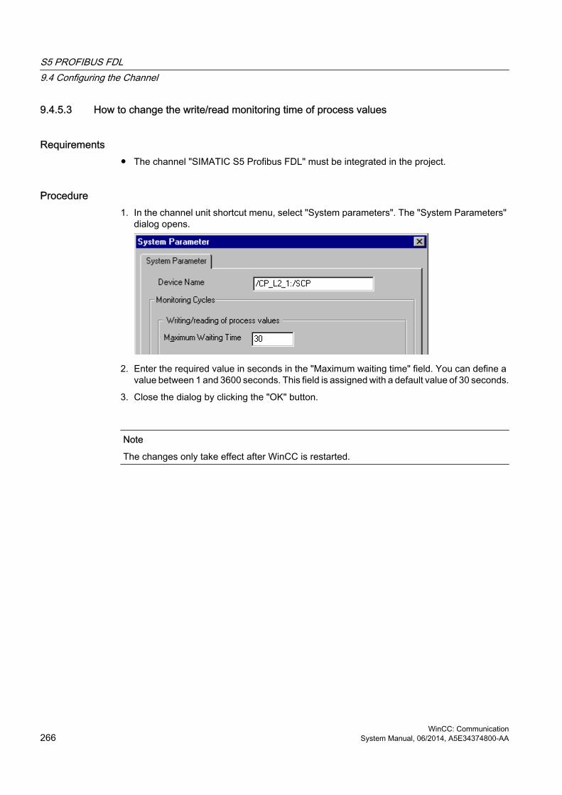
9.4.5.3 How to change the write/read monitoring time of process values
Requirements● The channel "SIMATIC S5 Profibus FDL" must be integrated in the project.
Procedure1. In the channel unit shortcut menu, select "System parameters". The "System Parameters"
dialog opens.
2. Enter the required value in seconds in the "Maximum waiting time" field. You can define a value between 1 and 3600 seconds. This field is assigned with a default value of 30 seconds.
3. Close the dialog by clicking the "OK" button.
Note
The changes only take effect after WinCC is restarted.
S5 PROFIBUS FDL9.4 Configuring the Channel
WinCC: Communication266 System Manual, 06/2014, A5E34374800-AA

9.5 Special Functions
9.5.1 Special functions of the "SIMATIC S5 Profibus FDL" Channel
IntroductionThe "SIMATIC S5 Profibus FDL" channel has some special functions, the functionality of which is described in this chapter.
9.5.2 Raw data tags of the "SIMATIC S5 Profibus FDL" channel
9.5.2.1 Raw data tags of the "SIMATIC S5 Profibus FDL" channel
Introduction A tag of the type "raw data type" is a data telegram.
Raw data tags are required for transferring user data blocks from/to the AS
A raw data tag used by SIMATIC S5 Profibus FDL can be a maximum of 220 bytes in length.
Raw data tag as byte arrayA raw data tag as byte array is handled like a normal process tag that is addressed via the address and length of the data block (for e.g. DB 100, DW 20, length 40 Byte).
Writing raw data tags using scriptsIf a raw data tag, which is longer than the tag length configured in WinCC, is written to S5 using a VB script, the write process is aborted.
Instead write the raw data tag via a C script using the "SetTagRaw" function. For this function, specify the length of the tags that are to be written.
9.5.2.2 How to configure raw data tags
Requirements1. The channel "SIMATIC S5 Profibus FDL" must be integrated in the project.
2. A connection must be defined in the channel unit "FDL (CP5412/A2-1)".
S5 PROFIBUS FDL9.5 Special Functions
WinCC: CommunicationSystem Manual, 06/2014, A5E34374800-AA 267

Procedure1. Select the connection for which a tag is to be configured.
2. Click the "Tags" tab below the table area.
3. Click in the top free cell of the "Name" column.Enter the name for the tag.
4. Select "Raw Data Type" in the "Data type" field.
5. Click the "Select" button to open the "Address properties" dialog.Open the "Address properties" dialog.For this purpose, click in the "Address" field and then on the button.
6. Mark the "Raw Data" check box.
7. Enter the length of the raw data block (in bytes) in the "Length" field.
8. In the "Data area" set the data area of the PLC where the data is located. If you select "DB" as data area, enter the number of the data block in the enabled "DB No." field.
9. Set up the addressing type in the "Addressing" field. The entries "Left byte", "Right byte", "Word" and "Double word" are possible for data type "Raw data type" of the WinCC tag.
10.Enter the value of the start address in the underlying field. The label on the left field depends on the entry in the Data Area and Addressing field, for e.g. "DW" for data area "DB" "Word" for addressing type.
11.Click "OK" to close all open dialogs.
9.5.3 Configuring the communication types
9.5.3.1 Configuring the communication types
IntroductionAn FDL connection can be configured so that WinCC runs as an active or passive partner.
If WinCC is configured as an active partner, the values are requested by the WinCC station.
S5 PROFIBUS FDL9.5 Special Functions
WinCC: Communication268 System Manual, 06/2014, A5E34374800-AA

If WinCC is configured as a passive partner, the transfer of values to the WinCC station is initiated by the AS.
9.5.3.2 How to configure an active data transfer
IntroductionThis section shows you how to configure an active data transfer to the address area in the AS.
Note
If more than one connection is configured, note that an SAP can only be assigned one time.
Requirements1. The channel "SIMATIC S5 Profibus FDL" must be integrated in the project.
2. A connection must be defined in the channel unit "FDL (CP5412/A2-1)".
3. You must know the SAP address defined by the AS.
S5 PROFIBUS FDL9.5 Special Functions
WinCC: CommunicationSystem Manual, 06/2014, A5E34374800-AA 269

Procedure1. Select the entry "Connection parameters" from the shortcut menu of the connection.
2. Enter the station address of the AS in the "PLC Station Address" field on the "Connection" tab.
3. The following settings must be made in the "READ - Function" area:
4. Activate the option "OS active, WinCC is the active partner".
5. Enter the SAP-ID of the WinCC station in the "Own SAP" field.
6. Enter the SAP-ID of the AS in the "Foreign SAP" field.
7. The following settings must be made in the "WRITE - Function" area:
8. Enter the SAP-ID of the WinCC station in the "Own SAP" field.
9. Enter the SAP-ID of the AS in the "Foreign SAP" field.
10.Click "OK" to close all open dialogs.
S5 PROFIBUS FDL9.5 Special Functions
WinCC: Communication270 System Manual, 06/2014, A5E34374800-AA
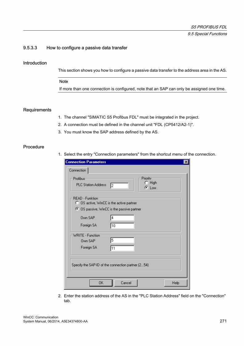
9.5.3.3 How to configure a passive data transfer
IntroductionThis section shows you how to configure a passive data transfer to the address area in the AS.
Note
If more than one connection is configured, note that an SAP can only be assigned one time.
Requirements1. The channel "SIMATIC S5 Profibus FDL" must be integrated in the project.
2. A connection must be defined in the channel unit "FDL (CP5412/A2-1)".
3. You must know the SAP address defined by the AS.
Procedure1. Select the entry "Connection parameters" from the shortcut menu of the connection.
2. Enter the station address of the AS in the "PLC Station Address" field on the "Connection" tab.
S5 PROFIBUS FDL9.5 Special Functions
WinCC: CommunicationSystem Manual, 06/2014, A5E34374800-AA 271

3. The following settings must be made in the "READ - Function" area:
4. Activate the option "OS passive, WinCC is the passive partner".
5. Enter the SAP-ID of the WinCC station in the "Own SAP" field.
6. Enter the SAP-ID of the AS in the "Foreign SAP" field.
7. The following settings must be made in the "WRITE - Function" area:
8. Enter the SAP-ID of the WinCC station in the "Own SAP" field.
9. Enter the SAP-ID of the AS in the "Foreign SAP" field.
10.Click "OK" to close all open dialogs.
S5 PROFIBUS FDL9.5 Special Functions
WinCC: Communication272 System Manual, 06/2014, A5E34374800-AA

9.6 Example of configuring the "SIMATIC S5 Profibus FDL" channel
9.6.1 Example of configuring the "SIMATIC S5 Profibus FDL" channel
IntroductionIn this example, you will configure an I/O Field in the Graphics Designer and assign the necessary values to the data handling blocks in the AS.
9.6.2 How to configure the data handling blocks in the AS
IntroductionIn this section, you will configure the standard function blocks OB 21 (L2ANLAUF) and OB 1 (L2SNDRCV) in the AS.
By default, the data traffic for the SIMATIC S5 connection by means of PROFIBUS FDL is handled by means of the following blocks.
Within the example, the following SAP numbers are used:
WinCC Automation deviceSAP number for the READ function
12 6
SAP number for the WRITE function
11 4
Blocks
Function BlockFor the startup OB 20, 21, 22 FB-L2ANLAUF (FB 9)For cyclic operation OB 1 FB-L2SNDRCV (FB 10)As internal work DBs for both FBs DB-L2DBVC3 (DB 10)
DB-L2DBVC4 (DB 11)DB-L2DBVC5 (DB 12)
Startup blocksThe communication parameters are defined in the startup blocks, the work DBs are logged in and the communication processor is synchronized. These work steps are executed by calling function block FB9 L2ANLAUF, for example.
S5 PROFIBUS FDL9.6 Example of configuring the "SIMATIC S5 Profibus FDL" channel
WinCC: CommunicationSystem Manual, 06/2014, A5E34374800-AA 273

Cyclic blockThe telegram traffic is handled in the cyclic FB. Received telegrams are entered in the destination data blocks. Should an error occur while this is being done, the telegram is rejected and an error message is issued. Telegrams that have to be sent will be specified by the user in a similar manner to the standard data handling blocks. An acknowledgement is sent when the transfer has been completed.
S5 PROFIBUS FDL9.6 Example of configuring the "SIMATIC S5 Profibus FDL" channel
WinCC: Communication274 System Manual, 06/2014, A5E34374800-AA

Requirements● The data handling blocks SYNCHRON, CONTROL, SEND and RECEIVE must be available
on the automation system.
Procedure1. The startup block (OB 20, 21, 22) is created in STEP5 by choosing the menu option "Editor"
"STEP5 Block" "in the program file". The program block is called "L2ANLAUF" in the example.
2. The following parameters must be preassigned:
– Interface number (SSNR) of the CP (e.g. the CP5431)
– The PROFIBUS address (RADR) of communication processor CP 5613 on the WinCC computer. This number must be unique in the network.
– The connection parameters of the request types being used, for example, are the parameters RVC4 (for write) and RVC5 (for read), which specify the SAPs of the WinCC station. These SAPs are created when the connection is being set up in WinCC.
– The request numbers (ANR4 and ANR5), which are set when the FDL connections are being configured for the communication processor are
– numbers of the work data blocks, DBX4 (for write) and DBX5 (for read)
3. An OB 1(cyclic operation) is created in the STEP5 software by choosing the menu option "Editor" "STEP5 Block" "in the program file". The program block is called "L2SNDRCV" in the example.
S5 PROFIBUS FDL9.6 Example of configuring the "SIMATIC S5 Profibus FDL" channel
WinCC: CommunicationSystem Manual, 06/2014, A5E34374800-AA 275

4. Communication with WinCC is performed by means of communication processor CP5431 and function block FB10 L2SNDRCV. When WinCC sends data and has to request data, only two applicable transfer parameters have to be specified for this purpose. These are the parameters DBX4 (for write) and DBX5 (for read), which specify the numbers of the two work data blocks for the request types being used. These SAPs are created when the connection is being set up in WinCC.
5. Load the STEP5 program into the automation device.This is done in STEP5 by choosing the menu option "Object" "Blocks" "Transfer"
"PLC file". Select the option "All blocks" in the "Selection" field to load all previously created blocks onto the automation system.
9.6.3 How to configure an I/O Field
IntroductionYou will configure an I/O Field in this section.
S5 PROFIBUS FDL9.6 Example of configuring the "SIMATIC S5 Profibus FDL" channel
WinCC: Communication276 System Manual, 06/2014, A5E34374800-AA

Requirements● The channel "SIMATIC S5 Profibus FDL" must be integrated in the project.
Procedure1. Choose the "New Connection" option from the shortcut menu of the channel unit "FDL
(CP5412/A2-1)" and set up a connection called "TestFDL".
2. Select the entry "Connection parameters" from the shortcut menu of the connection.The "Connection properties" dialog opens.Enter the station address of the AS in the "PLC Station Address" field.You can configure an FDL connection in such a way that WinCC is either an active or passive partner. If WinCC is configured as an active partner, the values are requested by the WinCC station. If WinCC is configured as a passive peer, the transfer of values to the WinCC station is initiated by the AS.Close all opened dialogs by clicking "OK"
3. Click the "Tags" tab below the table area.
4. Click in the top free cell of the "Name" column.Enter "FDLWord1_Test" as name.
5. In the "Data Type" field, set the data type to "Unsigned 16-bit value".
6. Open the "Address properties" dialog.For this purpose, click in the "Address" field and then on the button.
7. In the "Data area" set the data area of the PLC where the data is located. If you select "DB" as data area, enter the number of the data block in the enabled "DB No." field. Enter the byte address in the "DW" field.
8. Click "OK" to close all open dialogs.
9. You must integrate the smart object "I/O field" into a picture within Graphics Designer.
10.Connect the "I/O field" to a configured tag.
11.Activate the project by clicking the "Activate Runtime" button in the toolbar or by selecting "Activate Runtime" in the "File" menu. All changes to the configured tag are displayed in the "I/O field" in Runtime.
S5 PROFIBUS FDL9.6 Example of configuring the "SIMATIC S5 Profibus FDL" channel
WinCC: CommunicationSystem Manual, 06/2014, A5E34374800-AA 277


S5 Programmers Port AS511 1010.1 WinCC channel "SIMATIC S5 Programmers Port AS511"
IntroductionThe communication driver "SIMATIC S5 Programmers Port AS511" is utilized for the serial connection through a TTY interface to the SIMATIC S5 automation system.
This chapter describes
● how to configure the data transfer with the "SIMATIC S5 Programmers Port AS511" channel.
● how to configure a connection and a tag.
Channel UnitThe communication driver has one channel unit for controlling a COM port for the serial connection.
The following capability is available:
● Channel unit S5-AS511 for serial communication via a "Siemens-specific" protocol.
WinCC: CommunicationSystem Manual, 06/2014, A5E34374800-AA 279

10.2 Data type of the tags
IntroductionDefine the required tags for a logical connection. From the WinCC viewpoint, you can access the following data types:
● Binary tag
● Unsigned 8-bit value
● Signed 8-bit value
● Unsigned 16-bit value
● Signed 16-bit value
● Unsigned 32-bit value
● Signed 32-bit value
● Floating-point number 32-bit IEEE 754
● Text tag, 8-bit character set
● Raw data type
S5 Programmers Port AS51110.2 Data type of the tags
WinCC: Communication280 System Manual, 06/2014, A5E34374800-AA

10.3 Configuring the Channel
10.3.1 Configuring the "SIMATIC S5 Programmers Port AS511" channel
IntroductionThe following steps are required for configuring the channel "SIMATIC S5 Programmers Port AS511".
● Configuring the connection
● Configuring the tags
10.3.2 How to configure the connection
IntroductionThe process connection using a serial connection is possible with the SIMATIC S5 automation system. The AS 511 communication processor is used in the automation system.
No additional communication module is required in WinCC. Communication is set up via either the TTY port on a PG 760 or a COM Port that is part of the system's standard equipment. In the later case, an additional port converter is required V.24/V.28 <---> TTY.
This serial link supports transmission rates of up to 19200 baud.
The following procedure can be used to assign one of the PC's serial ports to the AS511-NT drivers.
Note
During communication between WinCC and a S5 automation system via the "AS511" channel, data blocks may not be transferred, created or deleted in the AS. The memory in the S5 may also not be compressed. This last restriction is the result of the absolute addressing of memory in the S5. If changes are necessary, the link to WinCC must be disconnected.
S5 Programmers Port AS51110.3 Configuring the Channel
WinCC: CommunicationSystem Manual, 06/2014, A5E34374800-AA 281

Procedure1. Select the connection under the channel unit "S5-AS511".
2. Select the entry "Connection parameters" from the shortcut menu of the connection.
3. In the "Port" field, select the port to be used for the serial link.
S5 Programmers Port AS51110.3 Configuring the Channel
WinCC: Communication282 System Manual, 06/2014, A5E34374800-AA

10.3.3 Configuring the tags
10.3.3.1 Configuring the tags
IntroductionFor a connection between WinCC and the AS via channel "SIMATIC S5 Programmers Port AS511", tags of different data types can be created within WinCC. This is described in the following section.
Note
Addresses of the tags are not checked for plausibility in WinCC. If an address is used, which is not available in the AS, the status "Addressing error" will be set.
In DB and DX data blocks, reads and writes can only be made up to address 255.
Times cannot be written.
10.3.3.2 How to configure the address of a tag
IntroductionThe tag address is entered according to the address structure of the SIMATIC S5.
Procedure1. Select the connection for which a tag is to be configured.
2. Click the "Tags" tab below the table area and select the tag.
3. Select the required data type (e.g. signed 8-bit value) from the "General" tab.
S5 Programmers Port AS51110.3 Configuring the Channel
WinCC: CommunicationSystem Manual, 06/2014, A5E34374800-AA 283

4. Open the "Address properties" dialog.For this purpose, click in the "Address" field and then on the button.Select the "SYSVAR" tab.
5. Click on the selection field to choose whether the tag should transfer the "PLC Type", the current status ("PLC Status") or other data ("PLC Data").
S5 Programmers Port AS51110.3 Configuring the Channel
WinCC: Communication284 System Manual, 06/2014, A5E34374800-AA

6. Only if you have selected "PLC data" will you have to click on the "Address" tab to define the S5 address of the tag.
7. Choose whether the tag is located in a data block, in an extended data block, in a flag area, an input range or an output range in the "Data Area" field.
8. If the tag is in a data block, the "DB No." field is also shown. Here, you enter the number of the data block.
9. The type of addressing is entered in the "Addressing" field. Normally, the default definition can be used.
10.Enter the address in the respective field (e.g. "DW ").
Frequently, the memory in the PLC can only be accessed by byte or word. When using binary and "8 Bit" tags, dialog "Bit-Byte-tag" is opened in addition to dialog "Address properties" and this can be used to change individual bits in the memory of the PLC as well. For this purpose, the addressed memory area is read from the PLC for every single write request and the
S5 Programmers Port AS51110.3 Configuring the Channel
WinCC: CommunicationSystem Manual, 06/2014, A5E34374800-AA 285

corresponding bits and/or bytes are modified. Afterwards, the data is written back to the PLC's memory.
Note
Changes that have been made by the PLC in a read data area are overwritten when writing back into the data area.
Depending on the type of tag, you can access the automation system's memory bit-wise or byte-wise.
Addresses of the tags are not checked for plausibility in WinCC. If an address is used, which is not available in the AS, the status "Addressing error" will be set.
In DB and DX data blocks, reads and writes can only be made up to address 255.
Times cannot be written.
10.3.3.3 How to configure a tag with bit-wise access
Procedure1. Select the connection for which a tag is to be configured.
2. Click the "Tags" tab below the table area.
3. Click in the top free cell of the "Name" column.Enter the name for the tag.
4. Set the "Binary tag" data type in the "Data Type" field.
S5 Programmers Port AS51110.3 Configuring the Channel
WinCC: Communication286 System Manual, 06/2014, A5E34374800-AA

5. Open the "Bit/Byte tag" dialog.For this purpose, click in the "Address" field and then on the button.
6. Click the "Select" button. The "Address properties" dialog is opened.
7. Select the addressing type of the PLC memory in the selection field.
8. Select the number of bit to be changed in the selection field.
10.3.3.4 How to Configure a Tag with Byte by Byte Access
Procedure1. Select the connection for which a tag is to be configured.
2. Click the "Tags" tab below the table area.
3. Click in the top free cell of the "Name" column.Enter the name for the tag.
4. In the field "Data Type", set the data type to "Unsigned 8-bit value" or "Signed 8-bit value".
S5 Programmers Port AS51110.3 Configuring the Channel
WinCC: CommunicationSystem Manual, 06/2014, A5E34374800-AA 287

5. Open the "Bit/Byte tag" dialog.For this purpose, click in the "Address" field and then on the button.
6. Click the "Select" button. The "Address properties" dialog is opened.
7. Select the addressing type of the PLC memory in the selection field.
8. Select the number of byte to be changed in the selection field.
S5 Programmers Port AS51110.3 Configuring the Channel
WinCC: Communication288 System Manual, 06/2014, A5E34374800-AA

S5 Serial 3964R 1111.1 WinCC channel "SIMATIC S5 Serial 3964R"
IntroductionThe communication driver "SIMATIC S5 Serial 3964R" is implemented for the serial link between a WinCC station and a SIMATIC S5 automation system.
This chapter describes
● how to configure the data transfer with the "SIMATIC S5 Serial 3964R" channel.
● how to configure a connection and a tag.
Channel UnitThe communication driver has one channel unit for controlling a COM port for the serial link.
The following capability is available:
● Channel unit S5-RK512 (3964R) for serial communication via the 3964R or 3964 protocol.
WinCC: CommunicationSystem Manual, 06/2014, A5E34374800-AA 289

11.2 Data type of the tags
IntroductionDefine the required tags for a logical connection. From the WinCC viewpoint, you can access the following data types:
● Binary tag
● Unsigned 8-bit value
● Signed 8-bit value
● Unsigned 16-bit value
● Signed 16-bit value
● Unsigned 32-bit value
● Signed 32-bit value
● Floating-point number 32-bit IEEE 754
● Text tag, 8-bit character set
● Raw data type
S5 Serial 3964R11.2 Data type of the tags
WinCC: Communication290 System Manual, 06/2014, A5E34374800-AA

11.3 Configuring the Channel
11.3.1 Configuring the "SIMATIC S5 Serial 3964R" channel
IntroductionThe following steps are required for configuring the channel "SIMATIC S5 Serial 3964R".
11.3.2 How to configure the connection
IntroductionThe process connection using a serial connection is possible with the SIMATIC S5 automation system. On the automation system, the communication processor CP 544 or a second, plug-in serial port is used on the CPU module (module receptacle SI2).
No additional communication module is required in WinCC. Communication takes place by means of the default COM ports available on the system.
This serial link supports transmission rates of up to 19200 baud.
Note
When the SIMATIC S5 is actively sending with job type "Pseudowrite", the message length must not exceed 64 words.
S5 Serial 3964R11.3 Configuring the Channel
WinCC: CommunicationSystem Manual, 06/2014, A5E34374800-AA 291

Procedure1. Select a connection and select "Connection parameters" from the shortcut menu.
2. Select the Serial 3964R tab.
3. Select the communications port (COM1 or COM2) for the connection in the "Port" field.
4. Set the data transfer speed to the value used in the "Baud rate" field of the "Procedure parameters" area. The priority in the case of an initiation conflict (simultaneous line bid by WinCC and the automation system) is set in the "Priority" field. The set priority must be different from that set in SIMATIC S5.
5. In the "Procedure data" area, select either the "3964" or "3964R" line protocol. You should only change the default values for the procedure data (such as acknowledgment time, character delay time, etc.) in exceptional cases. Make sure that they match the parameters on the automation system.
S5 Serial 3964R11.3 Configuring the Channel
WinCC: Communication292 System Manual, 06/2014, A5E34374800-AA

6. Now select the "Options" tab.
7. You can disable cyclic life beat monitoring and disable the automatic reconnection on the "Options" tab.
11.3.3 Configuring the tags
11.3.3.1 Configuring the tags
IntroductionFor a connection between WinCC and the AS via channel "SIMATIC S5 3964R", data types binary and byte can be defined within WinCC. The following describes how to configure a tag of these data types.
11.3.3.2 How to configure the address of the tag
IntroductionThe tag address is entered according to the address structure of the SIMATIC S5.
S5 Serial 3964R11.3 Configuring the Channel
WinCC: CommunicationSystem Manual, 06/2014, A5E34374800-AA 293
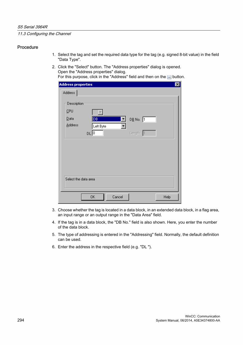
Procedure1. Select the tag and set the required data type for the tag (e.g. signed 8-bit value) in the field
"Data Type".
2. Click the "Select" button. The "Address properties" dialog is opened.Open the "Address properties" dialog.For this purpose, click in the "Address" field and then on the button.
3. Choose whether the tag is located in a data block, in an extended data block, in a flag area, an input range or an output range in the "Data Area" field.
4. If the tag is in a data block, the "DB No." field is also shown. Here, you enter the number of the data block.
5. The type of addressing is entered in the "Addressing" field. Normally, the default definition can be used.
6. Enter the address in the respective field (e.g. "DL ").
S5 Serial 3964R11.3 Configuring the Channel
WinCC: Communication294 System Manual, 06/2014, A5E34374800-AA

Note
Only read access is possible to the Inputs, Outputs, Timers and Counters address areas. Read and write access is possible to data blocks (DB, DX).
Do not use data word addresses which are greater than 255. Due to a system characteristic of the RK512, only data word addresses 0 to 255 are permissible.It is possible to configure larger addresses, but this leads to data corruption on all configured tags of this connection.
Frequently, the memory in the PLC can only be accessed by byte or word. When using binary and "8 Bit" tags, dialog "Bit-Byte-tag" is opened in addition to dialog "Address properties" and this can be used to change individual bits in the memory of the PLC as well. For this purpose, the addressed memory area is read from the PLC for every single write request and the corresponding bits and/or bytes are modified. Afterwards, the data is written back to the PLC's memory.
Note
Changes that have been made by the PLC in a read data area are overwritten when writing back into the data area.
Depending on the type of tag, you can access the automation system's memory bit-wise or byte-wise.
11.3.3.3 How to configure a tag with bit-wise access
Procedure1. Select the tag and set the "Binary tag" data type in the "Data Type" field.
2. Open the "Address properties" dialog.For this purpose, click in the "Address" field and then on the button.
3. Click the "Select" button. The "Bit/Byte tag" dialog is opened.
S5 Serial 3964R11.3 Configuring the Channel
WinCC: CommunicationSystem Manual, 06/2014, A5E34374800-AA 295

4. Select the "Access to a bit" check box and define the addressing for the bit.
5. Click the "Select" button. The "Address properties" dialog is opened.
6. Select the addressing type of the PLC memory in the selection field.
7. Select the number of bit to be changed in the selection field.
Note
With the S5, flags, inputs and outputs can be addressed byte by byte; data blocks (DB, DX) are addressed word by word.Only read access is possible to the Inputs, Outputs, Timers and Counters address areas. Read and write access is possible to data blocks (DB, DX).
S5 Serial 3964R11.3 Configuring the Channel
WinCC: Communication296 System Manual, 06/2014, A5E34374800-AA

11.3.3.4 How to Configure a Tag with Byte by Byte Access
Procedure1. Select the tag and set the data type in the "Data Type" field to "Unsigned 8-bit value" or
"Signed 8-bit value".
2. Open the "Address properties" dialog.For this purpose, click in the "Address" field and then on the button.
3. Click the "Select" button. The "Bit/Byte tag" dialog is opened.
4. Select the "Access to a byte" check box and define the addressing for the byte.
5. Click the "Select" button. The "Address properties" dialog is opened.
6. Select the addressing type of the PLC memory in the selection field.
7. Select the number of byte to be changed in the selection field.
Note
With the S5, flags, inputs and outputs can be addressed byte by byte; data blocks (DB, DX) are addressed word by word.Only read access is possible to the Inputs, Outputs, Timers and Counters address areas. Read and write access is possible to data blocks (DB, DX).
S5 Serial 3964R11.3 Configuring the Channel
WinCC: CommunicationSystem Manual, 06/2014, A5E34374800-AA 297


SIMATIC S7 Protocol Suite 1212.1 "SIMATIC S7 Protocol Suite" Channel
ContentThe "SIMATIC S7 Protocol Suite" channel supports communication between a WinCC station and the SIMATIC S7 automation systems. The suite supports a variety of protocols and types of networks.
This section shows you
● how to configure various connections and tags for the channel
● how to create a sample project
● how to use the channel's special functions such as the AR_SEND function, raw data tags and software redundancy
WinCC: CommunicationSystem Manual, 06/2014, A5E34374800-AA 299

12.2 WinCC Channel "SIMATIC S7 Protocol Suite"
Function principle The Channel "SIMATIC S7 Protocol Suite" is used to link SIMATIC S7-300 and SIMATIC S7-400 automation systems.
Depending on the communication hardware used, the system supports connections via the following channel units:
● Industrial Ethernet and Industrial Ethernet (II): For communication via a communication processor (such as CP 1612; CP1613) with SIMATIC NET Industrial Ethernet.
● MPI: For communication via the external MPI port of a programming device (e.g. PG 760/PC RI45), via an MPI communications processor or a communications module (e.g. CP 5511, CP 5613).
● Named Connections: to communicate with STEP 7 via a symbolic connection. These symbolic connections are configured using STEP 7 and are needed e.g. to provide high-availability communication with the PLC S7-400 in conjunction with the redundancy in H/F systems.
● PROFIBUS and PROFIBUS (II): For communication via a communication processor (such as CP 5613) with SIMATIC NET PROFIBUS.
● Slot-PLC: to communicate with a Slot PLC (e.g. WinAC Pro) that is installed as a PC card in the WinCC computer.
● Soft-PLC: to communicate with a Software PLC (e.g. WinAC Basis), that is installed as an application on the WinCC computer.
● TCP/IP: to communicate with networks using the TCP/IP protocol.
For more information regarding the diagnosis of channels and tags, refer to "Communication Diagnostics".
Detailed proceduresAdditional information and detailed examples of channel configuration can be found in the "WinCC V6 Communication Manual":
● http://support.automation.siemens.com/WW/view/en/21320307 (http://support.automation.siemens.com/WW/view/en/21320307)
For more information regarding diagnostics of channels and tags, refer to the "WinCC V7.2: Communication" manual, "Communication - Diagnostics":
● http://support.automation.siemens.com/WW/view/en/73568736 (http://support.automation.siemens.com/WW/view/en/73568736)
See alsoSoftware Redundancy - Connection-specific internal tags (Page 379)
"SIMATIC S7 Protocol Suite" Channel - Configuration (Page 307)
SIMATIC S7 Protocol Suite12.2 WinCC Channel "SIMATIC S7 Protocol Suite"
WinCC: Communication300 System Manual, 06/2014, A5E34374800-AA

Overview of the supported data types (Page 306)
Channel unit selection (Page 302)
Diagnosis of Channels and Tags (Page 463)
http://support.automation.siemens.com/WW/view/en/21320307 (http://support.automation.siemens.com/WW/view/en/21320307)
http://support.automation.siemens.com/WW/view/en/73568736 (http://support.automation.siemens.com/WW/view/en/73568736)
SIMATIC S7 Protocol Suite12.2 WinCC Channel "SIMATIC S7 Protocol Suite"
WinCC: CommunicationSystem Manual, 06/2014, A5E34374800-AA 301

12.3 Channel unit selection
IntroductionTo setup a communication link to an existing or planned network, a selection must be made for:
● one of the channel's channel units
● a suitable communication processor for the WinCC station
● a suitable communication module for a specific automation system
This section provides an overview of the various options.
There are two different types of communication processors for WinCC:
● Communication processors for the so-called Hardnet. They have their own microprocessors and reduce the load on the system's CPU. It is possible to use two different protocols at the same time (multi-protocol operation).
● Communication processors for the so-called Softnet. They do not have their own microprocessors. Only one protocol can be used at a time (mono-protocol operation).
Channel Unit AssignmentThe table below presents the assignment of the channel units of the Channel "SIMATIC S7 Protocol Suite" to networks and automation systems.
Channel unitof the channel
Communication Network
Automationsystem
MPI MPI S7-300 and S7-400PROFIBUS and PROFIBUS (II): PROFIBUS S7-300 and S7-400Industrial Ethernet + Industrial Ethernet (II)
Industrial Ethernet S7-300 and S7-400
TCP/IP Industrial Ethernetvia TCP/IP
S7-300 and S7-400
Named Connections Industrial Ethernet orPROFIBUS
S7-400 H/F Systems
Slot PLC "Soft K-Bus" (internal) PC (internal)Soft PLC "Soft K-Bus" (internal) PC (internal)
MPIFor communication with the S7-300 and S7-400 PLCs via MPI, Channel "SIMATIC S7 Protocol Suite" includes the "MPI" channel unit.
The MPI network corresponds in largest part to the PROFIBUS network with preset parameters and limitations with regard to the number of subscribers and the transfer rate. The same communication processors and modules are used for communication via MPI as for the PROFIBUS network. The same communication protocols are also used.
SIMATIC S7 Protocol Suite12.3 Channel unit selection
WinCC: Communication302 System Manual, 06/2014, A5E34374800-AA

Automation System Communication LinksThe S7-300 and S7-400 programmable controllers can communicate via a MPI network using their internal MPI port or a suitable communication module. The table shows the recommended components.
System CPU or Communication Module (recommended)S7-300 CPU 31x
CP 342-5CP 343-5
S7-400 CPU 41xCP 443-5 Ext.CP 443-5 Basic
Communication Processors for WinCCThe following table shows the communication processors recommended for connecting a WinCC station to a MPI network. Only one communication processor per WinCC computer can be used for the MPI communication. Each card must also have a driver suitable for the respective communication protocol.
Communication Processor (WinCC) Assembly/TypeCP 5613 PCI Card/ HardnetCP 5511 PCMCIA Card/ SoftnetCP 5611 PCI Card/ Softnet
PROFIBUSFor communication with the S7-300 and S7-400 PLCs via PROFIBUS, Channel "SIMATIC S7 Protocol Suite" includes the "PROFIBUS" and "PROFIBUS II" channel units.
The channel units support communication via the Hardnet and Softnet modules.
Automation System Communication LinksThe S7-300 and S7-400 programmable controllers can communicate via a PROFIBUS network using their internal port or a suitable communication module. The table shows the recommended components.
System CPU or Communication ModuleS7-300 CPU 31x
CP 342-5CP 343-5
S7-400 CPU 41xCP 443-5 Ext.CP 443-5 Basic
SIMATIC S7 Protocol Suite12.3 Channel unit selection
WinCC: CommunicationSystem Manual, 06/2014, A5E34374800-AA 303

Communication Processors for WinCCThe following table shows the communication processors recommended for connecting a WinCC station to the PROFIBUS. The "PROFIBUS" channel unit supports communication via Hardnet and Softnet cards. A WinCC station supports the use of up to two of these modules. Each communication processor must also have a driver suitable for the respective communication protocol.
Communication Processor (WinCC) Assembly/TypeCP 5613 PCI Card/ HardnetCP 5511 PCMCIA Card/ SoftnetCP 5611 PCI Card/ Softnet
Industrial Ethernet and TCP/IPIn WinCC, the Channel "SIMATIC S7 Protocol Suite" supports multiple channel units for communication via Industrial Ethernet:
● "Industrial Ethernet" and "Industrial Ethernet (II)" Channel Units for "ISO" Protocol with S7 Functions
● "TCP/IP" Channel Unit for "ISO-on-TCP" Protocol with S7 Functions
The channel units support communication via the Hardnet and Softnet modules.
Automation System Communication ModulesIf the S7-300 or S7-400 PLC should communicate via an Industrial Ethernet using the "ISO" or "ISO-on-TCP" protocol, it must be equipped with a suitable communication module. The table shows the recommended components.
System Communication modulefor Industrial Ethernet
Communication modulefor TCP/IP-Protocol
S7-300 CP 343-1 CP 343-1 TCPS7-400 CP 443-1 CP 443-1 TCP
CP 443-1 IT
Communication Processors for WinCCA WinCC station uses Industrial Ethernet to communicate via the "ISO" or "ISO-on-TCP" protocol with one of the communication processors recommended in the table below.
Each communication processor also has a driver suitable for each of the respective communication protocols.
SIMATIC S7 Protocol Suite12.3 Channel unit selection
WinCC: Communication304 System Manual, 06/2014, A5E34374800-AA

Communication Processor (WinCC) Assembly/TypeCP 1612 PCI Card/ SoftnetCP 1613 PCI Card/ HardnetCP 1512 PCMCIA Card/ Softnet
SIMATIC S7 Protocol Suite12.3 Channel unit selection
WinCC: CommunicationSystem Manual, 06/2014, A5E34374800-AA 305

12.4 Overview of the supported data types
IntroductionFor configuring a tag, you need to define data type and type conversion according to the data format in AS.
The table shows the data types supported by the channel and the use of type conversions.
Supported data types
Data Types Type conversionBinary tag NoSigned 8-bit value YesUnsigned 8-bit value YesSigned 16-bit value YesUnsigned 16-bit value YesSigned 32-bit value YesUnsigned 32-bit value YesFloating-point number 32-bit IEEE 754 YesText tag, 8-bit font NoRaw data type No
You will find additional information about type conversion in the "Communication" section.
SIMATIC S7 Protocol Suite12.4 Overview of the supported data types
WinCC: Communication306 System Manual, 06/2014, A5E34374800-AA

12.5 Configuring the Channel
12.5.1 "SIMATIC S7 Protocol Suite" Channel - Configuration
IntroductionThis section will show you how to configure the "SIMATIC S7 Protocol Suite" channel.
1. Installing the Channel
2. Channel unit selection
3. Configuring a connection
4. Tag configuration
System parameter configuration
Further information regarding the diagnosis of the channel, connection and tags can be found under "Communication Diagnosis".
See alsoSystem Parameters of the Channel Unit (Page 331)
Configuring the tags (Page 325)
Channel units of the "SIMATIC S7 Protocol Suite" channel (Page 308)
Diagnosis of Channels and Tags (Page 463)
12.5.2 How to configure the "SIMATIC S7 Protocol Suite" channel
IntroductionThis section will show you how to install the "SIMATIC S7 Protocol Suite" channel.
1. Installing the Channel
2. Channel unit selection
3. Creating a connection
4. Inserting a tag
5. Configuring the system parameters in a customized WinCC installation
Prerequisites:● The communication module is built in.
● The hardware driver has been installed.
● Cable connection to AS exists.
SIMATIC S7 Protocol Suite12.5 Configuring the Channel
WinCC: CommunicationSystem Manual, 06/2014, A5E34374800-AA 307

Procedure1. In the navigation area of the tag management, select the entry "Add new driver" in the
shortcut menu of node "Tag Management".
2. Select the driver "SIMATIC S7 Protocol Suite". The channel is set up and the communication driver is displayed in the tag management along with the channel units.
3. Select the desired channel unit and select the "New Connection" entry in the shortcut menu.
4. Enter the name of the connection.
5. Click the "Tags" tab below the table area.
6. Click in the top free cell of the "Name" column.Enter the name for the tag.
7. Select the desired data type in the "Data Type" field.You have the option of defining a start value and a substitute value for the tags in the "Properties" area.For a detailed description of configuring the tags for connecting a specific channel unit, close the dialog and continue with the topic "Configuring tags" within the respective channel unit.
8. Open the "Address properties" dialog.For this purpose, click in the "Address" field and then on the button.
9. Close both of the dialogs by clicking the "OK" button.
10.If your WinCC system and the communication hardware is non-standard, you also need to set the system parameters to the non-standard values. Additional information on this topic may be found under "System parameters".
12.5.3 Channel units
12.5.3.1 Channel units of the "SIMATIC S7 Protocol Suite" channel
IntroductionThe following chapters describe how to configure the channel units and a corresponding connection. There can be multiple connections in the same channel unit.
See also"TCP/IP" channel unit (Page 322)
"Soft PLC" channel unit (Page 321)
"Slot PLC" channel unit (Page 319)
Channel Units "PROFIBUS (I + II)" (Page 317)
"Named Connections" channel unit (Page 314)
SIMATIC S7 Protocol Suite12.5 Configuring the Channel
WinCC: Communication308 System Manual, 06/2014, A5E34374800-AA

"MPI" channel unit (Page 312)
Channel Units "Industrial Ethernet" + "Industrial Ethernet (II)" (Page 309)
12.5.3.2 "Industrial Ethernet (I+II)" channel units"
Channel Units "Industrial Ethernet" + "Industrial Ethernet (II)"
Principle of OperationThe channel unit "Industrial Ethernet" is used to connect WinCC to the S7 automation systems via the Industrial Ethernet. Communication is possible via the communications modules (CP), e.g. in the case of automation system S7-300 via CP 343-1 and in the case of S7-400 via CP 443-1.
In WinCC different communications processors can be used, e.g. CP 1613. Via the channel unit "Industrial Ethernet (II)" a second communications processor can be addressed. Because communication takes place via the "ISO" transport protocol, it is not necessary to configure the logical connection in the local database.
The function and configurations regarding these channel units are identical.
Typical unit terminology
Communications processorA communications processor (CP) is a module that supports communication between the WinCC computer and a specific network.
"ISO" transport protocolISO transport is a layer of the ISO-OSI reference model and offers services related to the transfer of data via connections. The transport layer handles data flow control, blocking and acknowledgment tasks.
The protocol defines the structure of the data traffic with regards to content on the physical line. It defines, among other things, the mode of operation, the procedure when establishing a connection, data backup or the transmission speed.
Industrial EthernetThe Industrial Ethernet is the most efficient subnet in the industrial environment. It is suitable for the factory and cell levels and facilitates the exchange of large data volumes over large distances between a large number of participants.
The Industrial Ethernet is an open communications network and is standardized in accordance with IEEE 802.3. Its prime advantages are its speed, simple extendibility and openness as well as high availability and worldwide utilization. The configuration process requires a minimum of effort.
SIMATIC S7 Protocol Suite12.5 Configuring the Channel
WinCC: CommunicationSystem Manual, 06/2014, A5E34374800-AA 309

See alsoConfiguring the tags (Page 325)
How to configure a "Industrial Ethernet" channel unit connection (Page 310)
How to configure a "Industrial Ethernet" channel unit connection
IntroductionIn addition to the channel unit, WinCC also requires a logical connection to communicate with the PLC. All the specific parameters are defined while establishing a logical connection.
For S7 automation systems, a communications module, e.g. a CP 343-1 in the S7-300 or a CP 443-1 in the S7-400, is used for the communication.
A communications processor, for example CP 1613, is used in WinCC. A second communications processor can be addressed/increased via the "Industrial Ethernet II" channel unit.
Further information regarding the diagnostics of the channel, connection and tags can be found under "Communication Diagnostics".
Requirements● The Channel "SIMATIC S7 Protocol Suite" must be integrated into the project.
Procedure1. Select the entry "New Connection" in the shortcut menu of the channel unit "Industrial
Ethernet". A new connection is created.
2. Enter a connection name, for example, "Test_Ind_Eth".
SIMATIC S7 Protocol Suite12.5 Configuring the Channel
WinCC: Communication310 System Manual, 06/2014, A5E34374800-AA

3. Select the "Connection parameters" connection from the shortcut menu.The "Connection properties - Industrial Ethernet" dialog opens.
4. Enter the station address of the automation system on the bus in the field "Ethernet Address".
5. Enter the number of the rack in which the CPU that is to be addressed is located in the "Rack Number" field.
6. The CPU's slot number in the specified rack must be entered in the corresponding field "Slot Number".
7. Activate the check box "Send/Receive Raw Data Block" if you wish to transfer BSEND/BRCV data blocks via the connection. If the check box is active, the field "Connection Resource" can be edited. Enter the hexadecimal value for the connection resource. This connection resource will be assigned by STEP7 when the connection is configured in the PLC.
8. Close both of the dialogs by clicking the "OK" button.
Note
When using an S7-300 or S7-400 with an external communications module, you must enter the Rack/Slot number of the CPU.
If the wrong Rack or Slot Number is entered, the communications link will not be established!
See alsoConfiguring the tags (Page 325)
How to configure the "SIMATIC S7 Protocol Suite" channel (Page 307)
Diagnosis of Channels and Tags (Page 463)
SIMATIC S7 Protocol Suite12.5 Configuring the Channel
WinCC: CommunicationSystem Manual, 06/2014, A5E34374800-AA 311

12.5.3.3 "MPI" channel unit
"MPI" channel unit
Principle of OperationThe MPI channel unit is used to connect WinCC to the SIMATIC S7-300 and S7-400 automation systems via MPI.
This can be done in WinCC via
● the internal MPI interface of the programming devices such as PG 760/PC RI45
● a communication processor such as CP 5613 (PCI card)
The so-called MPI module (ISA card) is also suitable - it exists but is hard to get. It was replaced by the communication processors.
In PLC, linking is done via the MPI interface of the CPU or a corresponding communication module.
Typical unit terminology
MPIMPI means Multi Point Interface and is a communication link where there can be multiple participants. The connection to the communication network takes place as follows:
● In PLC via the MPI interface of the CPU or a communication module,
● In WinCC via the built-in MPI interface, for e.g., of a programming device or a communication processor (network card).
Communications processorA communications processor (CP) is a module that supports communication between the WinCC computer and a specific network.
See alsoConfiguring the tags (Page 325)
How to configure a "MPI" channel unit connection (Page 312)
How to configure a "MPI" channel unit connection
IntroductionIn addition to the channel unit, WinCC also requires a logical connection to communicate with the PLC. All the specific parameters are defined while establishing a logical connection.
S7-300 and S7-400 PLCs either use the internal MPI interface or a communication module such as CP 342-5 (SIMATIC S7-300) or CP 443-5 (SIMATIC S7-400).
SIMATIC S7 Protocol Suite12.5 Configuring the Channel
WinCC: Communication312 System Manual, 06/2014, A5E34374800-AA

If WinCC is installed on a PG 760/PC RI45, the internal MPI interface can be used; otherwise, you need to have a built-in MPI module. Alternately, you can also use a communication module such as CP 5511 (PCMCIA card).
Further information regarding the diagnostics of the channel, connection and tags can be found under "Communication Diagnostics".
Requirements● The "SIMATIC S7 Protocol Suite" (communication) driver must be integrated into the
project.
Procedure1. Select the entry "New Connection" in the shortcut menu of the channel unit "MPI".
A new connection is created.
2. Enter "Test_MPI" as connection name.
3. Select the "Connection parameters" connection from the shortcut menu.The "Connection parameters - MPI" dialog opens.
4. Enter the station address in the Station Address field of the automation system on the bus in the appropriate field.
5. The field "Segment ID" is currently not supported. The value must remain at "0".
6. Enter the number of the rack in which the CPU that is to be addressed is located in the "Rack Number" field.
7. Enter the "Slot Number" of the CPU in the specified rack.
SIMATIC S7 Protocol Suite12.5 Configuring the Channel
WinCC: CommunicationSystem Manual, 06/2014, A5E34374800-AA 313

8. Activate the check box "Send/Receive Raw Data Block" if you wish to transfer BSEND/BRCV data blocks via the connection. If the check box is flagged, the field "Connection Resource" will also be active. Enter the hexadecimal value for the connection resource. This connection resource will be assigned by STEP7 when the connection is configured in the PLC.
9. Close both of the dialogs by clicking the "OK" button.
Note
When using an S7-300 or S7-400 with an external communications processor, you must enter the Rack/Slot number of the CPU.
If the wrong Rack or Slot Number is entered, the communications link will not be established!
While using a S7-300, for the link via the internal MPI interface of the CPU, the rack/ slot number = 0 must be given.
See alsoConfiguring the tags (Page 325)
How to configure the "SIMATIC S7 Protocol Suite" channel (Page 307)
12.5.3.4 "Named Connections" channel unit
"Named Connections" channel unit
Principle of OperationThis channel unit is used for setting up a symbolic connection configured using STEP 7. WinCC can thus access redundant and non-redundant connection via a symbolic connection name. The symbolic connections are required, for e.g., for high availability communication using S7-400 PLC in connection with redundancy in H/F systems.
The symbolic connection names are configured in STEP 7 using the NETPRO application. The connection names, connection parameters and the application names are stored in a database (*.XDB). This databased is automatically stored by the PLC/OS Engineering Tool "Mapper" in the corresponding WinCC project directory; however, it can also be copied outside this directory, for e.g. if you are not using the "Mapper".
Note
There should only be one XDB file per communication participant in the WinCC system. Hence, a XDB file should not be copied and used on multiple WinCC computers.
You have the following options to activate this database in WinCC:
SIMATIC S7 Protocol Suite12.5 Configuring the Channel
WinCC: Communication314 System Manual, 06/2014, A5E34374800-AA

● If the XDB file is located outside the project directory (for e.g. because the Mapper tool is not used), you need to enter the path and name of the XDB file in the "Set PG/PC interface" (Control Panel) in the STEP 7 Configuration tab before starting WinCC.
On starting WinCC, this XDB file is read from this external directory provided no file exists within the project directory. This procedure is helpful when multiple projects have to use the same centrally stored database.
● If the Mapper tool is used, it automatically copies the XDB file to the WinCC project directory. On starting WinCC and opening the project, the data is read from the S7 channel and entered in the registration database of Windows.
Thereafter, a connection can be configured in WinCC by assigning one of the symbolic connection names to the selected application name.
Note
The application and connection name can also be entered manually, for e.g. if an XDB file does not exist for the symbolic connection name or if the project is to be transferred to another computer. It is necessary to check the correct writing of the name in STEP 7 because there is no name validation in the CS mode.
Typical unit terminology
Communications processorA communications processor (CP) is a module that supports communication between the PLC and a specific network.
See alsoConfiguring the tags (Page 325)
How to configure a "Named Connections" channel unit connection (Page 315)
How to configure a "Named Connections" channel unit connection
IntroductionIn addition to the channel unit, WinCC also requires a logical connection to communicate with the S7-400 PLC via a symbolic connection.
For setting up a logical connection, one of the symbolic connection names listed in the "Connection name" field is assigned to a selected application name.
The symbolic connection names and application names are configured in STEP 7.
Further information regarding the diagnostics of the channel, connection and tags can be found under "Communication Diagnostics".
SIMATIC S7 Protocol Suite12.5 Configuring the Channel
WinCC: CommunicationSystem Manual, 06/2014, A5E34374800-AA 315

Requirements● The Channel "SIMATIC S7 Protocol Suite" must be integrated into the project.
Procedure1. Select the entry "New Connection" in the shortcut menu of the channel unit "Named
Connections". A new connection is created.
2. Enter a connection name, for example, "Test_NC".
3. Select the "Connection parameters" connection from the shortcut menu.The "Connection parameters - Named Connections" dialog opens.
4. In the Application name field, enter the application name that has been configured in STEP 7. Default value is WinCC.
5. In the Connection name field, enter the symbolic connection name that has been configured in STEP 7.
6. Close both of the dialogs by clicking the "OK" button.
Note
The application and connection name can also be entered manually, for e.g. if an XDB file does not exist for the symbolic connection name or if the project is to be transferred to another computer. It is necessary to check the correct writing of the name in STEP 7 because there is no name validation in the CS mode.
See alsoConfiguring the tags (Page 325)
How to configure the "SIMATIC S7 Protocol Suite" channel (Page 307)
SIMATIC S7 Protocol Suite12.5 Configuring the Channel
WinCC: Communication316 System Manual, 06/2014, A5E34374800-AA

12.5.3.5 "PROFIBUS (I+II)" channel units
Channel Units "PROFIBUS (I + II)"
Principle of OperationThe channel unit is used to connect WinCC to the SIMATIC S7-300 and S7-400 automation systems via a PROFIBUS network.
For the S7 automation systems, a communications module is used, e.g. a CP 342-5 in a S7-300 or a CP 443-5 in a S7-400.
A communications processor, for example CP 5613, is used in WinCC.
A second communications processor can be addressed via the "PROFIBUS II" channel unit. In this manner, the maximum number of connections is increased.
Typical unit terminology
PROFIBUSThe PROFIBUS is an open, nonproprietary communications system for the cell and field levels and has been designed for a maximum of 127 participants. The PROFIBUS is based on the European Standard EN 50170, Volume 2, PROFIBUS. PROFIBUS uses token passing with an underlying master/slave access procedure.
Communications processorA communications processor (CP) is a module that supports communication between the WinCC computer and a specific network.
See alsoConfiguring the tags (Page 325)
How to configure a "PROFIBUS" channel unit connection (Page 317)
How to configure a "PROFIBUS" channel unit connection
IntroductionIn addition to the channel unit, WinCC must also have a logical connection to communicate with the PLC. All the specific parameters are defined while establishing a logical connection.
For S7 automation systems, a communications module is used, e.g. a CP 342-5 in a S7-300 or a CP 443-5 in a S7-400.
A communications processor, for example CP 5613, is used in WinCC. A second communications processor can be addressed via the "PROFIBUS II" channel unit.
Further information regarding the diagnostics of the channel, connection and tags can be found under "Communication Diagnostics".
SIMATIC S7 Protocol Suite12.5 Configuring the Channel
WinCC: CommunicationSystem Manual, 06/2014, A5E34374800-AA 317

Requirements● The Channel "SIMATIC S7 Protocol Suite" must be integrated into the project.
Procedure1. Select the entry "New Connection" in the shortcut menu of the channel unit "PROFIBUS".
A new connection is created.
2. Enter "Test_PROFIBUS" as connection name.
3. Select the "Connection parameters" connection from the shortcut menu.The "Connection parameters - PROFIBUS" dialog opens.
4. Enter the "Station Address" of the automation system on the bus in the appropriate field.
5. The field "Segment ID" is currently not supported. The value must remain at "0".
6. Enter the "rack number" in which the CPU that is to be addressed is located.
7. Enter the "Slot Number" of the CPU in the specified rack.
8. Activate the check box "Send/Receive Raw Data Block" if you wish to transfer BSEND/BRCV data blocks via the connection. If the check box is flagged, the field "Connection Resource" will also be active. Enter the hexadecimal value for the connection resource. This connection resource will be assigned by STEP7 when the connection is configured in the PLC.
9. Close both of the dialogs by clicking the "OK" button.
SIMATIC S7 Protocol Suite12.5 Configuring the Channel
WinCC: Communication318 System Manual, 06/2014, A5E34374800-AA

Note
When starting up the PROFIBUS communication, PROFIBUS errors can occur if the communication processor was connected to the PROFIBUS while the WinCC computer was ON. Therefore, it is recommended that the computer be switched OFF before connecting it to the PROFIBUS. Otherwise, (in accordance with the PROFIBUS standard) multiple tokens may be generated on the bus, which will cause a bus error.
When using an S7-300 or S7-400 with an external communications module, you must enter the Rack/Slot number of the CPU.
If the wrong Rack or Slot Number is entered, the communications link will not be established!
See alsoConfiguring the tags (Page 325)
How to configure the "SIMATIC S7 Protocol Suite" channel (Page 307)
12.5.3.6 "Slot PLC" channel unit
"Slot PLC" channel unit
Principle of OperationChannel unit "Slot PLC" serves the communication between WinCC and up to four Slot PLC (WinAC Pro) installed in the WinCC computer. Since the Slot PLC has an integrated interface, no additional communication hardware is required for the connection between WinCC and Slot PLC.
See alsoConfiguring the tags (Page 325)
How to Configure a "Slot PLC" Channel Unit Connection (Page 319)
How to Configure a "Slot PLC" Channel Unit Connection
IntroductionIn order to communicate with the installed SPS cards, WinCC requires a logical connection in addition to the channel unit. All the specific parameters are defined while establishing a logical connection.
SIMATIC S7 Protocol Suite12.5 Configuring the Channel
WinCC: CommunicationSystem Manual, 06/2014, A5E34374800-AA 319

Further information regarding the diagnostics of the channel, connection and tags can be found under "Communication Diagnostics".
Requirements● The Channel "SIMATIC S7 Protocol Suite" must be integrated into the project.
● If several Slot PLC are to be configured, Slot PLC Version 3.4 is required.
Procedure1. Select the entry "New connection" in the shortcut menu of the channel unit "Slot PLC".
A new connection is created.
2. Enter a connection name, for example, "Test_SPLC".
3. Select the "Connection parameters" connection from the shortcut menu.The "Connection parameters - Slot PLC" dialog opens.
4. In the field "Station address", enter the station address of the Slot PLC on the Soft K-Bus.
5. In the field "Slot No.", enter the number of the slot in which the Slot PLC is installed.
6. Activate the check box "Send/Receive Raw Data Block" if you wish to transfer BSEND/BRCV data blocks via the connection.
7. If the check box is flagged, the field "Connection Resource" will also be active. Enter the hexadecimal value for the connection resource. This connection resource will be assigned by STEP 7 when the connection is configured within the PLC.
8. Close both of the dialogs by clicking the "OK" button.
Note
Connection parameters "Station Address" and "Slot No." must be identical for several installed Slot PLCs and must start with "Slot No." "3".
SIMATIC S7 Protocol Suite12.5 Configuring the Channel
WinCC: Communication320 System Manual, 06/2014, A5E34374800-AA

See alsoConfiguring the tags (Page 325)
How to configure the "SIMATIC S7 Protocol Suite" channel (Page 307)
12.5.3.7 "Soft PLC" channel unit
"Soft PLC" channel unit
Principle of OperationChannel unit "Slot PLC" serves the communication between WinCC and a Soft PLC (WinAC Basic) installed in the WinCC computer. No other communication hardware is required for connecting WinCC to the Soft PLC.
See alsoConfiguring the tags (Page 325)
How to configure a connection on the "Soft PLC" channel unit (Page 321)
How to configure a connection on the "Soft PLC" channel unit
IntroductionIn addition to the channel unit, WinCC must also have a logical connection to communicate with the Soft PLC. All the specific parameters are defined while establishing a logical connection.
Further information regarding the diagnostics of the channel, connection and tags can be found under "Communication Diagnostics".
Requirements● The Channel "SIMATIC S7 Protocol Suite" must be integrated into the project.
Procedure1. Select the entry "New connection" in the shortcut menu of the channel unit "Soft PLC".
A new connection is created.
2. Enter a connection name, for example, "Test_SOFTPLC".
SIMATIC S7 Protocol Suite12.5 Configuring the Channel
WinCC: CommunicationSystem Manual, 06/2014, A5E34374800-AA 321

3. Select the "Connection parameters" connection from the shortcut menu.The "Connection parameters - Slot PLC" dialog opens.
4. In the field "Station address", enter the station address of the Soft PLC on the Soft K-Bus.
5. In the field "Slot No.", enter the number of the slot. The slot number is configured in the hardware configuration of Soft PLC and is required when you want to use multiple Soft PLC in the same WinCC computer.
6. Activate the check box "Send/Receive Raw Data Block" if you wish to transfer BSEND/BRCV data blocks via the connection.
7. If the check box is flagged, the field "Connection Resource" will also be active. Enter the hexadecimal value for the connection resource. This connection resource will be assigned by STEP 7 when the connection is configured within the PLC.
8. Close both of the dialogs by clicking the "OK" button.
See alsoConfiguring the tags (Page 325)
How to configure the "SIMATIC S7 Protocol Suite" channel (Page 307)
12.5.3.8 "TCP/IP" channel unit
"TCP/IP" channel unit
Principle of OperationThe channel unit "TCP/IP" is used to connect WinCC to the automation systems SIMATIC S7-300 and S7-400 via an Industrial Ethernet with protocol "ISO-on-TCP Transport".
The protocol corresponds to the standard TCP/IP with the extension RFC 1006. This extension is necessary, since TCP/IP uses communication where there is no blocking of data.
SIMATIC S7 Protocol Suite12.5 Configuring the Channel
WinCC: Communication322 System Manual, 06/2014, A5E34374800-AA
In the case of the automation system S7-300, communication takes place via a communications module, e.g. CP 343-1 TCP, and via CP 443-1 TCP or CP 443-1 IT in the case of S7-400.
In WinCC a communications processor such as CP 1613 is used.
Because communication takes place via the ISO-on-TCP transport protocol, it is not necessary to configure the logical connection in the local database.
Typical unit terminology
Communications processorA communications processor (CP) is a module that supports communication between the WinCC computer and a specific network.
ISO transport protocolISO transport is a layer of the ISO-OSI reference model and offers services related to the transfer of data via connections. The transport layer handles data flow control, blocking and acknowledgment tasks.
The protocol defines the structure of the data traffic with regards to content on the physical line. It defines, among other things, the mode of operation, the procedure when establishing a connection, data backup or the transmission speed.
Industrial EthernetThe Industrial Ethernet is the most efficient subnet in the industrial environment. It is suitable for the factory and cell levels and facilitates the exchange of large data volumes over large distances between a large number of participants.
The Industrial Ethernet is an open communications network and is standardized in accordance with IEEE 802.3. Its prime advantages are its speed, simple extendibility and openness as well as high availability and worldwide utilization. The configuration process requires a minimum of effort.
See alsoConfiguring the tags (Page 325)
How to configure a "TCP/IP" channel unit connection (Page 323)
How to configure a "TCP/IP" channel unit connection
IntroductionIn addition to the channel unit, WinCC also requires a logical connection to communicate with the PLC. All the specific parameters are defined while establishing a logical connection.
In the case of the S7-300 automation system, communication takes place via a communications module, e.g. CP 343-1 TCP, and via CP 443-1 TCP or CP 443-1 IT in the case of S7-400.
In WinCC a communications processor such as CP 1613 is used.
SIMATIC S7 Protocol Suite12.5 Configuring the Channel
WinCC: CommunicationSystem Manual, 06/2014, A5E34374800-AA 323

Further information regarding the diagnostics of the channel, connection and tags can be found under "Communication Diagnostics".
Requirements● The Channel "SIMATIC S7 Protocol Suite" must be integrated into the project.
Procedure1. Select the entry "New Connection" in the shortcut menu of the "TCP/IP" channel unit.
A new connection is created.
2. Enter "Test_TCP" as connection name.
3. Select the "Connection parameters" connection from the shortcut menu.The "Connection parameters - TCP/IP" dialog opens.
4. Enter the Internet protocol address of the automation system on the bus in the field "IP Address".
5. Enter the number of the rack in which the CPU that is to be addressed is located in the "Rack Number" field.
6. The CPU's slot number in the specified rack must be entered in the corresponding field "Slot Number".
7. Activate the check box "Send/Receive Raw Data Block" if you wish to transfer BSEND/BRCV data blocks via the connection. If the check box is flagged, the field "Connection Resource" will also be active. Enter the hexadecimal value for the connection resource. This connection resource will be assigned by STEP7 when the connection is configured in the PLC.
8. Close both of the dialogs by clicking the "OK" button.
SIMATIC S7 Protocol Suite12.5 Configuring the Channel
WinCC: Communication324 System Manual, 06/2014, A5E34374800-AA

Note
When using an S7-300 or S7-400 with an external communications module, you must enter the Rack/Slot number of the CPU.
If the wrong Rack or Slot Number is entered, the communications link will not be established!
See alsoConfiguring the tags (Page 325)
How to configure the "SIMATIC S7 Protocol Suite" channel (Page 307)
12.5.4 Configuring the tags
12.5.4.1 Configuring the tags
IntroductionThe following sections describe how to configure the tags. It is different in the way the data area in the PLC is accessed and the data type of the WinCC tags.
Further information regarding the diagnosis of the channel, connection and tags can be found under "Communication Diagnosis".
See alsoHow to Configure a Text Tag (Page 329)
How to Configure a Tag with Word by Word Access (Page 328)
How to Configure a Tag with Byte by Byte Access (Page 327)
How to Configure a Tag with Bit by Bit Access (Page 325)
12.5.4.2 How to Configure a Tag with Bit by Bit Access
IntroductionThis section shows you how to configure a tag for bit by bit access for the address area in PLC.
SIMATIC S7 Protocol Suite12.5 Configuring the Channel
WinCC: CommunicationSystem Manual, 06/2014, A5E34374800-AA 325

Requirements● The Channel "SIMATIC S7 Protocol Suite" must be integrated into the project.
● A connection e.g. "Test_Ind_Eth" must be created in a channel unit, e.g. "Industrial Ethernet".
Procedure1. Select the connection "Test_Ind_Eth".
2. Click the "Tags" tab below the table area.
3. Click in the top free cell of the "Name" column.In the "Name" field, enter "ETH_Var1_bit" as the name for the tag.
4. Set the "Binary tag" data type in the "Data Type" field.
5. Open the "Address properties" dialog.For this purpose, click in the "Address" field and then on the button.In the "Data area" field, set the data area of the automation system where the data are located. If you select "DB" as data area, enter the number of the data block in the enabled "DB No." field.
6. You cannot change the "Bit" entry in the Addressing field because it is defined by the Binary Variable data type of the WinCC tag.
7. Enter the byte and bit address in the two fields below it. The label on the left field depends on the entry in the Data Area field, for e.g. "D" for data area "DB" and Binary Variable as type.
8. Check the quality code check-box if the tag is with quality code that is to be used in WinCC. For this, the code must also exist in the PLC. The check-box is enables only if the data area is selected as "DB".
9. Close both of the dialogs by clicking the "OK" button.
See alsoHow to configure the "SIMATIC S7 Protocol Suite" channel (Page 307)
SIMATIC S7 Protocol Suite12.5 Configuring the Channel
WinCC: Communication326 System Manual, 06/2014, A5E34374800-AA

12.5.4.3 How to Configure a Tag with Byte by Byte Access
IntroductionThis section shows you how to configure a tag for byte by byte access for the address area in PLC.
Requirements● The Channel "SIMATIC S7 Protocol Suite" must be integrated into the project.
● A connection e.g. "Test_Ind_Eth" must be created in a channel unit, e.g. "Industrial Ethernet".
Procedure1. Select the connection "Test_Ind_Eth".
2. Click the "Tags" tab below the table area.
3. Click in the top free cell of the "Name" column.In the "Name" field, enter "ETH_Var1_byte" as the name for the tag.
4. In the "Data Type" field, set the data type to "Unsigned 8-bit value".
5. Open the "Address properties" dialog.For this purpose, click in the "Address" field and then on the button.In the "Data area" field, set the data area of the automation system where the data are located. If you select "DB" as data area, enter the number of the data block in the enabled "DB No." field.
6. You cannot change the "Bit" entry in the Addressing field because it is defined by the "Unsigned 8-bit value" data type of the WinCC tag.
7. Enter the byte address in the field below. The label on the left field depends on the entry in the Data Area field, for e.g. "D" for data area "DB" and "Unsigned 8-bit value" as type.
SIMATIC S7 Protocol Suite12.5 Configuring the Channel
WinCC: CommunicationSystem Manual, 06/2014, A5E34374800-AA 327

8. Check the quality code check-box if the tag is with quality code that is to be used in WinCC. For this, the code must also exist in the PLC. The check-box is enables only if the data area is selected as "DB".
9. Close both of the dialogs by clicking the "OK" button.
See alsoHow to configure the "SIMATIC S7 Protocol Suite" channel (Page 307)
12.5.4.4 How to Configure a Tag with Word by Word Access
IntroductionThis section shows you how to configure a tag for word by word access for the address area in PLC.
This procedure is also applicable for tags with length of 4 byte ("double word") and more.
Requirements● The Channel "SIMATIC S7 Protocol Suite" must be integrated into the project.
● A connection e.g. "Test_Ind_Eth" must be created in a channel unit, e.g. "Industrial Ethernet".
Procedure1. Select the connection "Test_Ind_Eth".
2. Click the "Tags" tab below the table area.
3. Click in the top free cell of the "Name" column.In the "Name" field, enter "ETH_Var3_word" as the name for the tag.
4. In the "Data Type" field, set the data type to "Unsigned 16-bit value".
SIMATIC S7 Protocol Suite12.5 Configuring the Channel
WinCC: Communication328 System Manual, 06/2014, A5E34374800-AA

5. Open the "Address properties" dialog.For this purpose, click in the "Address" field and then on the button.In the "Data area" field, set the data area of the automation system where the data are located. If you select "DB" as data area, enter the number of the data block in the enabled "DB No." field.
6. You cannot change the "Word" entry in the Addressing field because it is defined by the "Unsigned 16-bit value" data type of the WinCC tag.
7. Enter the numeric value of the address in the Addressing field. The label on the left field depends on the entry in the Data Area field, for e.g. "DBW" for "Unsigned 16-bit value" as type.
8. Check the quality code check-box if the tag is with quality code that is to be used in WinCC. For this, the code must also exist in the PLC. The check-box is enables only if the data area is selected as "DB".
9. Click "OK" to close all open dialogs.
See alsoHow to configure the "SIMATIC S7 Protocol Suite" channel (Page 307)
12.5.4.5 How to Configure a Text Tag
IntroductionThis section show you how to configure a text tag.
For a text tag in the SIMATIC S7 Protocol Suite channel, WinCC only supports S7 string type consisting of a control word and the actual user data of the string:
SIMATIC S7 Protocol Suite12.5 Configuring the Channel
WinCC: CommunicationSystem Manual, 06/2014, A5E34374800-AA 329

● To configure a text tag in WinCC, enter the address of the control word that exists in the PLC memory before the user data. The first byte of the control word contains the customized maximum length of the string, the second byte the actual length.
● To insert the data structure in the PLC memory, you must note that the length of the text tag configured in WinCC is extended by 2 bytes of the control word. If the data structures of the text tag are inserted in the memory directly one after the other, then the subsequent data will get overwritten.
● New mapping is required for switching the PCS-7 version from V4.01 to V5.0 SP1 because in the versions before V5.0 the address of the user data was also mentioned while configuring the text tags; from version V5.0 onwards the address of the control word is to be given.
● While reading, the control word is read along with the user data and the current length is evaluated in the second byte. Only the user data according to the current length included in the second control byte is transferred at the text tags of WinCC.
● While writing, the actual length of the string is ascertained ("0" character) and the control byte with the current length is sent to the PLC along with the user data.
Requirements● The Channel "SIMATIC S7 Protocol Suite" must be integrated into the project.
● A connection e.g. "Test_Ind_Eth" must be created in a channel unit, e.g. "Industrial Ethernet".
Procedure1. Select the connection "Test_Ind_Eth".
2. Click the "Tags" tab below the table area.
3. Click in the top free cell of the "Name" column.In the "Name" field, enter "ETH_Var3_Text" as the name for the tag.
4. In the Data Type field, set "Text tag, 8-bit font" as the data type.
SIMATIC S7 Protocol Suite12.5 Configuring the Channel
WinCC: Communication330 System Manual, 06/2014, A5E34374800-AA

5. Open the "Address properties" dialog.For this purpose, click in the "Address" field and then on the button.In the "Data area" set the data area of the PCL where the data is located. If you select "DB" as data area, enter the number of the data block in the enabled "DB No." field.
6. The entry in the Addressing field can only be changed to Byte or Word because it is defined by the "Text tag, 8-bit font" data type of the WinCC tag.
7. Enter the numeric value of the address in the Addressing field. Mention the address of the control word. The label on the left field depends on the entry in the Data Area field, for e.g. "DBW" for Word as type.
8. Check the quality code check-box if the tag is with quality code that is to be used in WinCC. For this, the code must also exist in the PLC. The check-box is enables only if the data area is selected as "DB".
9. Click "OK" to close all open dialogs.
See alsoHow to configure the "SIMATIC S7 Protocol Suite" channel (Page 307)
12.5.5 System parameters
12.5.5.1 System Parameters of the Channel Unit
IntroductionIf you require a configuration that deviates from the WinCC standard settings, you will therefore be able to make all the required changes using the "System Parameter" dialog of the channel unit.
The following can be modified:
● the logical device name
● the use of the cyclic read service in the AS
SIMATIC S7 Protocol Suite12.5 Configuring the Channel
WinCC: CommunicationSystem Manual, 06/2014, A5E34374800-AA 331

Logical Device NameCommunication between WinCC and the automation system takes place via logical device names. These names are assigned during the installation of the communications card and are unit-specific. This field will be filled with a default unit-specific entry, e.g. "MPI" in the case of channel unit "MPI".
Using cyclic reading services in the PLCIt is possible to specify whether or not the cyclic read services of S7-PLC (also referred to as cyclic tag services) should be used. These cyclic read services group the tags that are to be read cyclically into individual request and transfer these to the PLC. The PLC will transfer the required data immediately on receipt of the request and will also transfer the data each time the cycle time elapses.
When the cyclic read services are activated, modification transfers can also be used. The data will then only be transferred when the values have changed. The function must be supported by the PLC.
Note
The system parameters on the SIMATIC S7 and Unit tabs are unit-specific and can thus be set separately for each channel unit of the channel.
See alsoHow to Change the Logical Device Name (Page 335)
How to Configure the System Parameters (Page 333)
Cyclic read services in PLC (Page 332)
12.5.5.2 Cyclic read services in PLC
IntroductionIn the system parameters of the "SIMATIC S7 Protocol Suite" channel, it is also possible to specify whether or not the cyclic read services of the S7-AS(also referred to as cyclic tag services) should be used. These cyclic read services group the tags that are to be read cyclically into individual request and transfer these to the PLC. The PLC will transfer the required data immediately on receipt of the request and will also transfer the data each time the cycle time elapses. When the requested data is no longer required, e.g. in the case of a screen change, WinCC will delete the cyclic read service in the PLC.
In normal cases, use should be made of the cyclic read services in the PLC. For this reason, the corresponding check box is already activated (default setting) in the system parameters of the channel unit. This setting should only be changed if you do not wish to use the cyclic services.
Modification transfers can only be used when the cyclic read services are activated. The data will then only transferred from the AS when a value has changed and only once per AS cycle. The function must be supported by the PLC.
SIMATIC S7 Protocol Suite12.5 Configuring the Channel
WinCC: Communication332 System Manual, 06/2014, A5E34374800-AA

The use of the cyclic read services and modification transfers relieves both the AS and AS-OS communication, since read requests need not be continually sent to the AS and processed there.
In the case of acyclic read services, the tags that are to be read are combined in an individual request and transferred to the PLC. The PLC only sends the required data once. The formation of the cycle for the request is carried out by WinCC.
The number of cyclic read services in a CPUThe number of cyclic read services will depend on the resources that are available in the S7-PLC. A maximum of four cyclic services are available for an S7-300 max. and a maximum of 32 for an S7-416 or 417. This number applies for all participants communicating with the PLC, i.e. if several WinCC systems are communicating with an S7-PLC, they will have to share the resources that are available. If the maximum number of resources is exceeded, access to a further cyclic read service will be refused. WinCC will then have to request this data using acyclic read requests and will also have to execute cycle formation.
Requesting external tags in scriptsThe utilization of the cyclic read service has no influence on the initial update once a picture has been opened if the picture that has been selected does not contain any scripts that request external tags using the function "GetTagWord()". If scripts are executed with "GetTagWord()" when a picture is opened, the incorrect configuration of this script could result in new tag requests being sent to this channel repeatedly following a picture change. If external tags are required in a script, "Tag" should be entered as a trigger event.
12.5.5.3 How to Configure the System Parameters
IntroductionIn this section, we will show you how to configure the system parameters of the Channel "SIMATIC S7 Protocol Suite".
The "System Parameters" dialog comprises two tabs:
● SIMATIC S7 tab
● Unit tab
The system parameters on the SIMATIC S7 and Unit tabs are unit-specific and can thus be set separately for each channel unit of the channel.
These tabs are identical for all channel units of the S7 channel. Consequently, the dialog for the channel unit "MPI" is used in all examples.
Any changes that are made to the parameter values will only take effect after WinCC has been restarted.
Note
When copying the project to another computer, the settings on the Unit tab will be retained, the settings on the SIMATIC S7 tab, however, will not.
SIMATIC S7 Protocol Suite12.5 Configuring the Channel
WinCC: CommunicationSystem Manual, 06/2014, A5E34374800-AA 333

Requirements● The Channel "SIMATIC S7 Protocol Suite" must be integrated into the project.
Procedure1. Select the Channel "SIMATIC S7 Protocol Suite" in Tag Management. Open the dialog
"System Parameters" using the pop-up menu of the desired channel unit.
2. Select the SIMATIC S7 tab. Place a tick in the check boxes "by AS" and "with modification transfer", if you want to activate cyclic reading of tags by the channel and the use of modification transfers. If available, the cyclic services in the PLC will be used here. Further information can be found under "PLC Cyclic Read Services".
3. Activate the check box "Enable" in the "Lifebeat Monitoring" area if you wish to use this function. In the Interval field enter the time interval in seconds for transferring the lifebeat telegrams.In the Monitoring Time field enter the seconds value for monitoring the response to a lifebeat telegram.
4. If WinCC should indicate that communication is faulty when the S7-CPU is in the Stop status, activate the check box "Enable" in the "CPU Stop Monitoring" area.
SIMATIC S7 Protocol Suite12.5 Configuring the Channel
WinCC: Communication334 System Manual, 06/2014, A5E34374800-AA

5. Select the Unit tab. A name, which will depend on the communications processor installed, will be displayed in the field "Logical Device Name". You should only change this name if you have selected a different name when installing the communications processor. Further information can be found under "Changing Logical Device Names".
6. If only one communications processor has been installed for this communication type, activate the check box "Set Automatically", if the device name should be set automatically when Runtime is started.
7. Activate the check box "Write with Priority", if the processing of write requests should take priority over the processing of read requests.
8. Close the dialog with the "OK" button.
See alsoHow to Change the Logical Device Name (Page 335)
Cyclic read services in PLC (Page 332)
12.5.5.4 How to Change the Logical Device Name
IntroductionCommunication with the S7 takes place via logical device names. These names are assigned during the installation of the communications processor and are unit-specific.
Certain presettings have now been established for the device names depending on the communications processor that has been installed. These are listed in the table "Default Device Names" below.
The tabs for all units of the S7 channel are identical and, for this reason, the dialog for the channel unit "MPI" is shown in the description.
SIMATIC S7 Protocol Suite12.5 Configuring the Channel
WinCC: CommunicationSystem Manual, 06/2014, A5E34374800-AA 335

Default Device Names
Channel Unit Default Device NameIndustrial Ethernet CP_H1_1:Industrial Ethernet (II) CP_H1_2:MPI MPINamed Connections VM/PROFIBUS CP_L2_1:PROFIBUS (II) CP_L2_2:Slot PLC SLOT_PLCSoft PLC SOFT_PLCTCP/IP CP-TCPIP
Requirements● The Channel "SIMATIC S7 Protocol Suite" must be integrated into the project.
● A connection must be created to a channel unit e.g. "MPI".
Procedure1. Select the desired channel unit in Tag Management.
2. Open the dialog window "System Parameters" using the pop-up menu.
3. Select the Unit tab.
4. Specify a device name in the field "Logical Device Name". You can either select an entry from the selection list or enter a new name manually.All possible names will be determined by the "Configure PG/PC Interface" (Control Panel) tool. If this has not been installed, only the device name that is currently set will be displayed. If you specify a different logical device name, a message will be displayed.Manual entries should only be made if the target station uses a communications card which is not installed on the configuring station.
5. Close the dialog by clicking the "OK" button.
Note
Logical devices names must be exactly the same - to the letter - as in the device settings. This being the case, the default logical device names for the "Industrial Ethernet"and "PROFIBUS" have, for example, a colon at the end of the name.
Any changes that are made to the parameter values will only take effect after WinCC has been restarted.
SIMATIC S7 Protocol Suite12.5 Configuring the Channel
WinCC: Communication336 System Manual, 06/2014, A5E34374800-AA

12.6 Special functions
12.6.1 Special functions of the "SIMATIC S7 Protocol Suite" Channel
IntroductionThe SIMATIC S7 Protocol Suite contains some special functions; their functionality is described in this chapter.
See alsoSoftware Redundancy (Page 377)
Raw data tags of the Channel "SIMATIC S7 Protocol Suite" (Page 369)
Data exchange with the S7 function block AR_SEND (Page 337)
12.6.2 Data exchange with the S7 function block AR_SEND
12.6.2.1 Data exchange with the S7 function block AR_SEND
IntroductionThe S7 function block AR_SEND in the S7-400 AS is used to transfer process values to the process value archives.
Principle of OperationTo transfer PLC process values to a process value archive in WinCC, the S7-400 PLC has an integrated function component called SFB 37 "AR_SEND".
The basic function of AR_SEND component can supply data to archive tag. Data can be supplied to multiple tags if the AR_ID-Subnumber is used. If AR_SEND component is used, the process values are not sent individually to the archive; they are first collect in PLC and transferred as a package. This reduces the load on the used network.
In a PLC, you can use a CPI-dependent number of AR_SEND components (for e.g. CPU 416 max. 32 AR_SEND). A AR_ID can in turn be assigned to aach AR_SEND component. The sub-number is used to increase the amount of transferable process data because up to 4095 sub-numbers are possible for each AR_ID.In reality, the number of archive tags per AR_SEND component is limited by the maximum length of the data area to be transferred. For more information about "The Structure and Parameters of Data Block Structures", please see the description of the "Number of Process Values" parameter.
AR_ID and AR_ID-Subnumber establish the assignment between data in the PLC and the archive tags and are defined using other parameters while configuring the data structure in
SIMATIC S7 Protocol Suite12.6 Special functions
WinCC: CommunicationSystem Manual, 06/2014, A5E34374800-AA 337

the databases in the PLC.This assignment is configured in WinCC where as the other parameters are evaluated automatically.
SFB 37 "AR_SEND" must have first been configured in the PLC and the data block structure must have been done because configuration in WinCC is based on these values in the PLC. For information about configuring the AR_SEND function component can be found in the S7-400 PLC documentation.
Overview of AR_SEND Variants
Variants: AR_SEND for ...
Number of process-controlled archive tags for each AR_SEND
Intended use
an archive tag a For transferring process values for an archive tag where the process values can also be read in very small time intervals.
multiple archive tags corresponds to the number AR_ID-Subnumbers
For transferring process values for multiple archive tags where the process values can also be read in very small time intervals.
multiple archive tags (optimized)
corresponds to the number AR_ID-Subnumbers
For cyclic data supply to maximum number of archive tags each one value each at one time
See alsoAR_SEND variant for multiple archive tags (Page 350)
How to configure the AR _SEND variant for multiple archive tags (Page 367)
How to configure the AR _SEND variant for an archive tag (Page 364)
AR_SEND variant for multiple archive tags (optimized) (Page 362)
AR_SEND variant for an archive tag (Page 345)
12.6.2.2 Data Block - Structure and Parameters
IntroductionBefore data is transferred from a PLC with the "AR_SEND" function block, it is first organized as one or more data blocks. The structure of a data block depends on various parameters, e.g. whether a time stamp or the process value's data type is appended to the AR_SEND variant used.
The parameters used in data blocks are described below. The individual parameter values are set in the data block in the AS and in the "AR_SEND" function block parameters.
The parameters are checked when the data block is evaluated in WinCC. If WinCC detects an error in the structure of the data block or if the archive tag configuration does not match the received data, an entry with the following structure will be recorded in the WinCC Diagnosis logbook:
SIMATIC S7 Protocol Suite12.6 Special functions
WinCC: Communication338 System Manual, 06/2014, A5E34374800-AA

"Date, Time, 1003080 ,4 ,user name, computer name, NRMS7PMC, PdeReceive: Unknown parameter AR_SEND from connection connectionname ...+ additional information for error description"
If the message system has been configured with the WinCC System Messages, this diagnosis entry will also trigger the OS process control message numbered 1003080. The text of the logbook entry will be found in this message's comment.
Structure of a Data BlockEach data block consists of a header and a user data area:
● The header contains information about the process values and their cycle, and possibly a time stamp.
● The user data area contains the actual process values.
One or more data blocks form the data area to be transferred.
Note
In the data blocks, each line represents two bytes. Process values can be one or more bytes long, depending on their data type. Further information can be found in the description of the "Number of Process Values" parameter.
Description of parameters
Header TypeThe Header Type defines the type of information that is contained in the header.
SIMATIC S7 Protocol Suite12.6 Special functions
WinCC: CommunicationSystem Manual, 06/2014, A5E34374800-AA 339
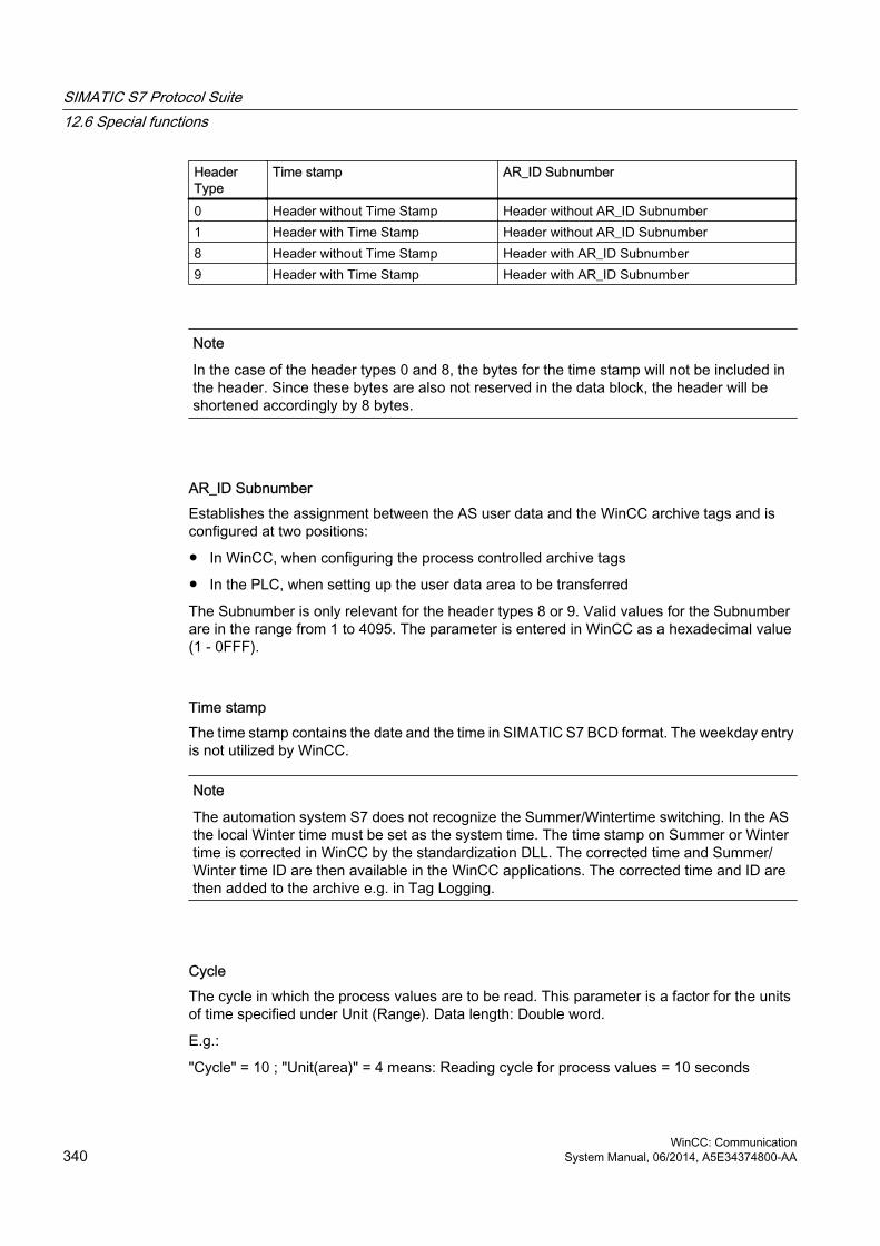
Header Type
Time stamp AR_ID Subnumber
0 Header without Time Stamp Header without AR_ID Subnumber1 Header with Time Stamp Header without AR_ID Subnumber8 Header without Time Stamp Header with AR_ID Subnumber9 Header with Time Stamp Header with AR_ID Subnumber
Note
In the case of the header types 0 and 8, the bytes for the time stamp will not be included in the header. Since these bytes are also not reserved in the data block, the header will be shortened accordingly by 8 bytes.
AR_ID SubnumberEstablishes the assignment between the AS user data and the WinCC archive tags and is configured at two positions:
● In WinCC, when configuring the process controlled archive tags
● In the PLC, when setting up the user data area to be transferred
The Subnumber is only relevant for the header types 8 or 9. Valid values for the Subnumber are in the range from 1 to 4095. The parameter is entered in WinCC as a hexadecimal value (1 - 0FFF).
Time stampThe time stamp contains the date and the time in SIMATIC S7 BCD format. The weekday entry is not utilized by WinCC.
Note
The automation system S7 does not recognize the Summer/Wintertime switching. In the AS the local Winter time must be set as the system time. The time stamp on Summer or Winter time is corrected in WinCC by the standardization DLL. The corrected time and Summer/Winter time ID are then available in the WinCC applications. The corrected time and ID are then added to the archive e.g. in Tag Logging.
CycleThe cycle in which the process values are to be read. This parameter is a factor for the units of time specified under Unit (Range). Data length: Double word.
E.g.:
"Cycle" = 10 ; "Unit(area)" = 4 means: Reading cycle for process values = 10 seconds
SIMATIC S7 Protocol Suite12.6 Special functions
WinCC: Communication340 System Manual, 06/2014, A5E34374800-AA

Unit (Type)Specifies the type of time information and modifies the parameter "Number of Process Values".
No. Meaning1 The process values are read at equal intervals.
Start time is mentioned in the timestamp of the header and is mandatory. The time interval between the process values is defined by the time units in the "Units (Range)" and the factor "Cycle".
2 Each process value has a timestampA time stamp given perhaps in the header will not be evaluated. The format corresponds to the time stamp in the header with a length of 8 bytes.
3 Each process value has a relative time difference in units of time with a data length of 2 words.The absolute time is the sum of the time stamp in the header (= start time) and the relative time difference in the time unit set in "Unit(Range)". A time stamp entry in the header is mandatory.
4 Each process value contains the AR_ID-Subnumber.The time stamp given in the header applies for the process value. A time stamp entry in the header is mandatory.
Units (Range)Specifies the units of time used for Unit (Type) = 1 or 3.
No. Meaning1 Reserved2 Reserved3 Milliseconds4 Seconds5 Minutes6 Hours7 Days
Process Data - Data TypeThe process values are stored directly in the S7 format.
No. S7 data type WinCC Data Type0 BYTE BYTE1 WORD WORD2 INT SWORD3 DWORD DWORD4 DINT SDWORD5 REAL FLOAT
SIMATIC S7 Protocol Suite12.6 Special functions
WinCC: CommunicationSystem Manual, 06/2014, A5E34374800-AA 341

Number of process valuesDepending on the entry in "Unit (Type)", the transferred data area can contain a specific number of process values. The number is limited by the maximum length of the transferred data area - 16 Kbytes.
Please note the resource restrictions when using the S7 functions "AR_SEND" and "BSEND/BRCV" to communicate with a S7-400, i.e. no more than 16 Kbytes of data can be simultaneously sent by the AS to WinCC using AR_SEND and/or BSEND/BRCV.
Note
In the case of the AR_SEND variant "Multiple Archive Tags", the following limitation applies for this parameter:
The data blocks for the various archive tags must always begin on a word boundary. Therefore, in the case of the combination "Data Type Process Value" = 0 (BYTE) and "Unit (Type)" = 1 (Process value with equally spaced time intervals) an even number of process values (=Bytes) must be entered for the parameter "Number of Process Values". This restriction only applies for this AR_SEND variant and this combination of data type and "Unit (Type)".
Example:
1x BSEND with a max. of 16 Kbytes
or 1x AR_SEND with 8 Kbytes + 1x BSEND with 8 Kbytes
or 1x AR_SEND with 10 Kbytes + 1x AR_SEND with 2 Kbytes + 1x BSEND with 4 Kbytes
Unit(Type)
The meaning of the number of process values
1 Reading process values at equal time intervals:8000 process values of the data type WORD or INT or 4000 values of data type DWORD, DINT or REAL can be transferred.
2 Process values with timestamp:Each element of the user data area consists of a timestamp (8 bytes) and a value. Therefore, 1600 process values of the data type WORD or INT or 1333 values of data type DWORD, DINT or REAL can be transferred.
3 Process values with time difference:Each element of the user data area consists of a timestamp (4 bytes) and a value. Therefore, 2666 process values of the data type WORD or INT or 2000 values of data type DWORD, DINT or REAL can be transferred.
4 Process value contains AR_ID-Subnumber (AR-SEND with multiple variables - optimized)In Type 4 , the process value consists of one word with the AR_ID-Subnumber (Value range: 1 - 0x0FFF) and one value. Thus, the user data area consists of an array of process values preceded by AR_ID Subnumbers. Therefore, 3992 process values of the data type WORD or INT or 2660 values of data type DWORD, DINT or REAL can be transferred.
SIMATIC S7 Protocol Suite12.6 Special functions
WinCC: Communication342 System Manual, 06/2014, A5E34374800-AA
Note
The AR_ID Subnumbers given in the data blocks must all be configured in WinCC. WinCC will stop interpreting the user data, if a not-configured subnumber is found.
The data blocks for the various archive tags must always begin on a word boundary. Therefore, with the data type BYTE and "Unit (Type)" = 1 (Process value with equally spaced time intervals), an even number of process values (=Bytes) must be entered for the parameter "Number of Process Values". This restriction only applies for this AR_SEND variant and this combination of data type and "Unit (Type)".
See alsoHow to configure the AR _SEND variant for multiple archive tags (Page 367)
How to configure the AR _SEND variant for an archive tag (Page 364)
AR_SEND variant for multiple archive tags (optimized) (Page 362)
AR_SEND variant for multiple archive tags (Page 350)
AR_SEND variant for an archive tag (Page 345)
12.6.2.3 Overview of the properties of the AR_SEND variants
IntroductionOn the basis of examples, the tables show the properties and possible parameter values for different AR_SEND variants.
The tables do not display all of the possible combinations.
The columns "Header Type" to "Process Value Data Type" are presented in the order that they appear in the header.
Note
The values for AR_ID and AR_ID Subnumber are set together with those of the other parameters while configuring the function block "AR_SEND" and the data structure in the data block in the AS.
SIMATIC S7 Protocol Suite12.6 Special functions
WinCC: CommunicationSystem Manual, 06/2014, A5E34374800-AA 343

Variants for an Archive Tag
Example /Property
E.g.-No.
Header type
Date / Time(Timestampt in header)
Cycle factor
Unit(Type)
Units(range)
AR_ID-Subno.
Data typeof process val.
max. numberof proc.val.
Process value structurein the e.g.
Each process value (byte) with its own time stamp
1 0 does not exist
0 2 0 0 01; 23; 4; 5
320016001333
8 byte time stamp + 1 Byte process value
Process value with equally spaced time stamp
2 1 Relevant >=1 1 3 to 7 0 01; 23; 4; 5
1600080004000
1 word process value
Each process value (word) with its own time stamp
3 1 not relevant
0 2 0 0 01; 23; 4; 5
320016001333
8 byte time stamp + 1 word process value
Each process value with time difference
4 1 Relevant >=1 3 3 to 7
0 01; 23; 4; 5
533226662000
8 byte time stamp+ 1 Byte process value
Variants for Multiple Archive Tags
Example /Property
E.g.-No.
Header type
Date / Time(Timestampt in header)
Cycle factor
Unit(Type)
Units(range)
AR_ID-Subno.
Data typeof process val.
max. numberof proc.val.
Process Value structure in the e.g.
Each process value (byte) with its own time stamp
5 8 does not exist
0 2 0 1 to 4095
01; 23; 4; 5
320016001333
8 byte time stamp + 1 Byte process value
Process value with equally spaced time stamp
6 9 Relevant >=1 1 3 to 7 1 to 4095
01; 23; 4; 5
1600080004000
1 word process value
SIMATIC S7 Protocol Suite12.6 Special functions
WinCC: Communication344 System Manual, 06/2014, A5E34374800-AA

Example /Property
E.g.-No.
Header type
Date / Time(Timestampt in header)
Cycle factor
Unit(Type)
Units(range)
AR_ID-Subno.
Data typeof process val.
max. numberof proc.val.
Process Value structure in the e.g.
Each process value (word) with its own time stamp
7 9 not relevant
0 2 0 1 to 4095
01; 23; 4; 5
320016001333
8 byte time stamp + 1 word process value
Each process value with time difference
8 9 Relevant 0 3 3 to 7
1 to 4095
01; 23; 4; 5
533226662000
8 byte time stamp+ 1 Byte process value
Variants for Multiple Archive Tags - Optimized
Example /Property
E.g.-No.
Header type
Date / Time(Timestampt in header)
Cycle factor
Unit(Type)
Units(range)
AR_ID-Subno.
Data typeof process val.
max. numberof proc.val.
Process value structurein the e.g.
Each process value with an AR_ID Subnumber
9 1 Relevant 0 4 0 0 1; 23; 4; 5
39922660
1 Word Subnumber+ 1 Word process value
See alsoAR_SEND variant for multiple archive tags (optimized) (Page 362)
AR_SEND variant for multiple archive tags (Page 350)
AR_SEND variant for an archive tag (Page 345)
12.6.2.4 AR_SEND variant for an archive tag
IntroductionThis variant can be used to supply an archive tag with process values. It can also be used with older versions of WinCC (prior to V5.0).
SIMATIC S7 Protocol Suite12.6 Special functions
WinCC: CommunicationSystem Manual, 06/2014, A5E34374800-AA 345

The properties of this variant:● The Header Type must be 0 or 1, i.e. without AR_ID Subnumber and with/without time
stamp.
● The AR_ID Subnumber in the header will not be evaluated.
● In WinCC, the archive tag name does not contain an AR_ID Subnumber, since only the process values for an archive tag will be transferred.
An example of the data area's structureThe data area to be transferred consists of one data block.
See alsoExample 4 for data block structure: An archive tag; each process value with relative time stamp (time difference) (Page 349)
Example 3 for data block structure: An archive tag; each process value has its own time stamp (Page 348)
Example 2 for data block structure: One archive tag; equally spaced time stamp (Page 347)
Example 1 for data block structure: An archive tag; each process value has a time stamp (Page 347)
Overview of the properties of the AR_SEND variants (Page 343)
SIMATIC S7 Protocol Suite12.6 Special functions
WinCC: Communication346 System Manual, 06/2014, A5E34374800-AA

12.6.2.5 Example 1 for data block structure: An archive tag; each process value has a time stamp
IntroductionIn this example, the process values are transferred for one archive tag only. There is no time stamp in the header and the corresponding number of bytes are also not reserved. Hence, each process value (1byte) is preceded by a time stamp (8byte).
Data type of the process values is BYTE.
Data block structure in the data component
See alsoData Block - Structure and Parameters (Page 338)
12.6.2.6 Example 2 for data block structure: One archive tag; equally spaced time stamp
IntroductionIn this example, the process values are transferred for one archive tag.
SIMATIC S7 Protocol Suite12.6 Special functions
WinCC: CommunicationSystem Manual, 06/2014, A5E34374800-AA 347

The equally spaced time stamp of one second is formed using the parameters "Cycle" = 1 and "Unit (Range)" = 4 (= seconds).
Data type of the process values is WORD.
Data block structure in the data component
See alsoData Block - Structure and Parameters (Page 338)
12.6.2.7 Example 3 for data block structure: An archive tag; each process value has its own time stamp
IntroductionIn this example, the process values are transferred for one archive tag only. The time stamp in the header is not important. Hence, each process value (1Word) is preceded by a time stamp (8byte).
Data type of the process values is SWORD.
SIMATIC S7 Protocol Suite12.6 Special functions
WinCC: Communication348 System Manual, 06/2014, A5E34374800-AA

Data block structure in the data component
See alsoData Block - Structure and Parameters (Page 338)
12.6.2.8 Example 4 for data block structure: An archive tag; each process value with relative time stamp (time difference)
IntroductionIn this example, the process values are transferred for one archive tag with time stamp.
The parameter "Unit(Type)" = 3 gives each process value a time difference (4Byte) for the time stamp in the header. The unit of time difference is set by the parameter "Unit(range)" = 4 in seconds.
Data type of the process values is DWORD.
SIMATIC S7 Protocol Suite12.6 Special functions
WinCC: CommunicationSystem Manual, 06/2014, A5E34374800-AA 349

Data block structure in the data component
See alsoData Block - Structure and Parameters (Page 338)
12.6.2.9 AR_SEND variant for multiple archive tags
IntroductionWith this variant, you can supply process values to one or more archive tags. For each archive tag, an AR_ID Subnumber will be assigned and a data block will be created in the data area to be transferred.
"x" process values can be transferred for each AR_ID Subnumber. For more information about "The Structure and Parameters of Data Block Structures", please see the description of the "Number of Process Values" parameter.
The time stamp for the value of an archive tag is taken or derived from the data area to be transferred in accordance with the given "Unit (Type)" and "Unit (Range)". It is then sent on to the WinCC process value archive.
SIMATIC S7 Protocol Suite12.6 Special functions
WinCC: Communication350 System Manual, 06/2014, A5E34374800-AA

The properties of this variant:● The Header Type must be 8 or 9 (with/without time stamp and with AR_ID Subnumber).
● For every AR_ID Subnumber, a data block must be created in the data area to be transferred.
● The AR_ID Subnumber in each data block must be greater than zero.
● In WinCC, the archive tag name has an AR_ID Subnumber.
Note
The AR_ID Subnumbers given in the data blocks must all be configured in WinCC. WinCC will stop interpreting the user data, if a not-configured subnumber is found.
The data blocks for the various archive tags must always begin on a word boundary. Therefore, in the case of the combination "Data Type Process Value" = 0 (BYTE) and "Unit (Type)" = 1 (Process values with equally spaced time intervals) an even number of process values (=Bytes) must be entered for the "Number of Process Values" parameter. This restriction only applies for this AR_SEND variant and this combination of data type and "Unit (Type)".
SIMATIC S7 Protocol Suite12.6 Special functions
WinCC: CommunicationSystem Manual, 06/2014, A5E34374800-AA 351

An example of the data area's structureThe data area to be transferred consists of one or more data blocks corresponding to the number of archive tags to be supplied.
SIMATIC S7 Protocol Suite12.6 Special functions
WinCC: Communication352 System Manual, 06/2014, A5E34374800-AA

SIMATIC S7 Protocol Suite12.6 Special functions
WinCC: CommunicationSystem Manual, 06/2014, A5E34374800-AA 353

See alsoExample 8 for data block structure: Multiple archive tags; process values with relative time stamp (time difference) (Page 360)
Example 7 for data block structure: Multiple archive tags; each process value has its own time stamp (Page 358)
Example 6 for data block structure: Multiple archive tags; equally spaced time stamp (Page 356)
Example 5 for data block structure: Multiple archive tags; each process value has its own time stamp (Page 354)
Overview of the properties of the AR_SEND variants (Page 343)
12.6.2.10 Example 5 for data block structure: Multiple archive tags; each process value has its own time stamp
IntroductionIn this example, process values are transferred for multiple archive tags.
The data blocks for the different archive tags are located one after the other in the data component. A different AR_ID-Subnumber is entered in each data block.
There is no time stamp in the header and the corresponding number of bytes for it are also not reserved. Hence, each process value (1byte) is preceded by a time stamp (8byte).
Data type of the process values is BYTE.
SIMATIC S7 Protocol Suite12.6 Special functions
WinCC: Communication354 System Manual, 06/2014, A5E34374800-AA

Data block structure in the data component
See alsoData Block - Structure and Parameters (Page 338)
SIMATIC S7 Protocol Suite12.6 Special functions
WinCC: CommunicationSystem Manual, 06/2014, A5E34374800-AA 355
12.6.2.11 Example 6 for data block structure: Multiple archive tags; equally spaced time stamp
IntroductionIn this example, process values are transferred for multiple archive tags. The data blocks for the different archive tags are located one after the other in the data component. A different AR_ID-Subnumber is entered in the header in each data block.
The equally spaced time stamp of one second is formed using the parameters "Cycle" = 1 and "Unit (Range)" = 4 (= seconds).
Data type of the process values is WORD.
SIMATIC S7 Protocol Suite12.6 Special functions
WinCC: Communication356 System Manual, 06/2014, A5E34374800-AA

Data block structure in the data component
See alsoData Block - Structure and Parameters (Page 338)
SIMATIC S7 Protocol Suite12.6 Special functions
WinCC: CommunicationSystem Manual, 06/2014, A5E34374800-AA 357

12.6.2.12 Example 7 for data block structure: Multiple archive tags; each process value has its own time stamp
IntroductionIn this example, process values are transferred for multiple archive tags. The data blocks for the different archive tags are located one after the other in the data component. A different AR_ID-Subnumber is entered in each data block.
The time stamp in the header is not important. Hence, each process value (1Word) is preceded by a time stamp (8byte).
Data type of the process values is SWORD.
SIMATIC S7 Protocol Suite12.6 Special functions
WinCC: Communication358 System Manual, 06/2014, A5E34374800-AA

Data block structure in the data component
SIMATIC S7 Protocol Suite12.6 Special functions
WinCC: CommunicationSystem Manual, 06/2014, A5E34374800-AA 359

See alsoData Block - Structure and Parameters (Page 338)
12.6.2.13 Example 8 for data block structure: Multiple archive tags; process values with relative time stamp (time difference)
IntroductionIn this example, the process values are transferred for one archive tag with time stamp.
The data blocks for the different archive tags are located one after the other in the data component. A different AR_ID-Subnumber is entered in each data block.
The parameter "Unit(Type)" = 3 gives each process value a time difference (4Byte) for the time stamp in the header. The unit of time difference is individually defined by the "Unit(Range)" parameter for each archive tag and hence for each data block.
Data type of the process values is DWORD.
SIMATIC S7 Protocol Suite12.6 Special functions
WinCC: Communication360 System Manual, 06/2014, A5E34374800-AA

Data block structure in the data component
See alsoData Block - Structure and Parameters (Page 338)
SIMATIC S7 Protocol Suite12.6 Special functions
WinCC: CommunicationSystem Manual, 06/2014, A5E34374800-AA 361

12.6.2.14 AR_SEND variant for multiple archive tags (optimized)
IntroductionThis variant is to be used when the maximum number of archive tags should each be supplied a process value at one time. In this case, the data area to be transferred consists of just one data block and each process value has just its AR_ID Subnumber and its associated value.
The data type is the same for the process values of all of the archive tags in this data block.
The properties of this variant:● The Header Type must be 1 (with time stamp and without AR_ID Subnumber).
● The AR_ID Subnumbers for the associated process values in the data block must be greater than zero. The AR_ID Subnumber in the header will not be evaluated.
● The "Unit (Type)" parameter must be 4, i.e. the process value has an AR_ID Subnumber.
● The "Units (Range)" parameter must be 0, i.e. the time stamp in the Header is valid for all process values and there are no relative times.
● In WinCC, the archive tag name has an AR_ID Subnumber.
Note
If a process value has an AR_ID Subnumber for which no WinCC archive tag is found, this will result in an entry in the WinCC Diagnosis Log. The remaining process values will then continue to be processed.
SIMATIC S7 Protocol Suite12.6 Special functions
WinCC: Communication362 System Manual, 06/2014, A5E34374800-AA
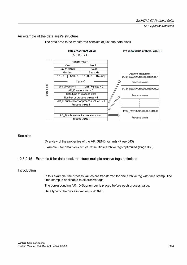
An example of the data area's structureThe data area to be transferred consists of just one data block.
See alsoOverview of the properties of the AR_SEND variants (Page 343)
Example 9 for data block structure: multiple archive tags;optimized (Page 363)
12.6.2.15 Example 9 for data block structure: multiple archive tags;optimized
IntroductionIn this example, the process values are transferred for one archive tag with time stamp. The time stamp is applicable to all archive tags.
The corresponding AR_ID-Subnumber is placed before each process value.
Data type of the process values is WORD.
SIMATIC S7 Protocol Suite12.6 Special functions
WinCC: CommunicationSystem Manual, 06/2014, A5E34374800-AA 363

Data block structure in the data component
See alsoData Block - Structure and Parameters (Page 338)
12.6.2.16 How to configure the AR _SEND variant for an archive tag
IntroductionThere are a number of variants for using the AR_SEND function to exchange data. For the "One Archive Tag" variant, only the AR_ID is used. The AR_ID Subnumber is not used.
The AR_ID is used to establish the assignment of the data in the AS to the archive tags and is configured together with other parameters while configuring the data blocks and the SFB 37 "AR_SEND" function block in the AS.
In WinCC, this allocation is performed in the properties for the process controlled tag. This assignment is the only configuration that is necessary in WinCC and will be described in this section.
SIMATIC S7 Protocol Suite12.6 Special functions
WinCC: Communication364 System Manual, 06/2014, A5E34374800-AA

The other parameters in WinCC need not be configured, since they are evaluated automatically.
Note
To use this variant with just the AR_ID, the Header Type must be configure as 0 or 1. The AR_ID Subnumber must be set to zero.
Since they do not have an AR_ID Subnumber, all of the archive tags, which were configured before WinCC Version V5.0, can be used with this variant.
Since WinCC Version 5.1 Hotfix 4 it has been possible to specify an alias for the archive tag name with process-controlled tags or to use the internal names generated by the system. The name generated by the system contains the name of the assigned raw data tag instead of the raw data ID from Version V5.1 HF4. In projects migrated to a version from V5.1 HF4, the archive tag names can be used in their original format or can be converted. The names are converted by once opening and closing the properties dialog box of the process-controlled archive tags. An alias does not have to be assigned.
If in a project all external tags are remapped using the "AS-OS-Transfer" function, the archive tag name must therefore be converted once to the new structure! The new structure is then maintained.
Requirements● The "AR_SEND" function block and the data block structure must first be configured in the
AS and this configuration information must be available during the following procedure.
● The Channel "SIMATIC S7 Protocol Suite" must be integrated into the project.
● A connection e.g. "Test_Ind_Eth" must be created in a channel unit, e.g. "Industrial Ethernet".
● A process value archive must be configured in the "Tag Logging" editor.
Procedure1. In the channel "SIMATIC S7 Protocol Suite", select the connection which should be used
for the data transfer.
2. Click the "Tags" tab below the table area.
3. Click in the top free cell of the "Name" column.Enter the name "Var_raw_arsend" for the tag. The name can be no longer than 24 characters. The raw data tag name becomes part of the archive tag name during the configuration of the process-controlled tag and is therefore limited to this length.
4. Select "Raw Data Type" in the "Data type" field.
5. Open the "Address properties" dialog.For this purpose, click in the "Address" field and then on the button.
SIMATIC S7 Protocol Suite12.6 Special functions
WinCC: CommunicationSystem Manual, 06/2014, A5E34374800-AA 365

6. Mark the "Raw Data" check box. In the "Raw Data Type" area select the type "Archive Data Link". Click "OK" to close all open dialogs.
7. Open the "Tag Logging" editor and in the shortcut menu of a process value archive select "New Process Controlled Tag". The "Properties of process controlled tag" dialog will open.
8. Click on "Select" to open a selection dialog and then select the raw data tag that should be used to supply the archive tags. In this example, that is "VAR_raw_arsend". Close the dialog by clicking "OK".
9. In the "Conversion DLL" field, set the entry "nrms7pmc.nll". Click on "Options". An input dialog opens.
10.Enter the AR_ID as a hexadecimal value. The value is defined through the configuration in the AS.Clear the check box "Subnumber" because there is no subnumber used in this AR_SEND variant.Close the dialog by clicking "OK".
11.The "Internal Archive Tag Name" field shows the internal archive tag name generated by the system. It contains the name of the assigned raw data tag and the AR_ID. In the "Archive Tag Name" field, if required, you can define an alias for this archive tag. If no alias is entered, the internal archive tag name is used for management in the process value archive and for addressing the archive tag in WinCC.
SIMATIC S7 Protocol Suite12.6 Special functions
WinCC: Communication366 System Manual, 06/2014, A5E34374800-AA

12.Close the dialog by clicking "OK".
13.Save your changes and close Tag Logging.
12.6.2.17 How to configure the AR _SEND variant for multiple archive tags
IntroductionThere are a number of variants for using the AR_SEND function to transfer data for multiple archive tags.
● Use the "Multiple Archive Tags" variant to supply multiple values to multiple archive tags at various times.
● Use the "Multiple Archive Tags - optimized" variant to supply one value each to the maximum number of archive tags at one time.
The AR_ID and AR_ID Subnumber are used in both of these variants.
AR_ID and AR_ID-Subnumber establish the assignment between the data in the AS and the archive tag. They are defined in the AS with other parameters when configuring the data blocks and the function module SFB 37 "AR_SEND".
In WinCC, this allocation is performed in the properties for the process controlled tag. This assignment is the only configuration that is necessary in WinCC and will be described in this section. The other parameters in WinCC need not be configured, since they are evaluated automatically.
Note
To use the AR_ID Subnumber, the Header Type must be configured as 8 or 9.
Archive tags configured in WinCC Version V5.0 have no AR_ID Subnumber and can therefore only be used in the "One Tag" variant.
Since WinCC Version 5.1 Hotfix 4 it has been possible to specify an alias for the archive tag name with process-controlled tags or to use the internal names generated by the system. The name generated by the system contains the name of the assigned raw data tag instead of the raw data ID from Version V5.1 HF4. In projects migrated to a version from V5.1 HF4, the archive tag names can be used in their original format or can be converted. The names are converted by once opening and closing the properties dialog box of the process-controlled archive tags. An alias does not have to be assigned.
If in a project all external tags are remapped using the "AS-OS-Transfer" function, the archive tag name must therefore be converted once to the new structure! The new structure is then maintained.
SIMATIC S7 Protocol Suite12.6 Special functions
WinCC: CommunicationSystem Manual, 06/2014, A5E34374800-AA 367

Requirements● The "AR_SEND" function block and the data block structure must first be configured in the
AS and this configuration information must be available during the following procedure.
● The Channel "SIMATIC S7 Protocol Suite" must be integrated into the project.
● A connection e.g. "Test_Ind_Eth" must be created in a channel unit, e.g. "Industrial Ethernet".
● A process value archive must be configured in the "Tag Logging" editor.
Procedure1. In the channel "SIMATIC S7 Protocol Suite", select the connection which should be used
for the data transfer.
2. Click the "Tags" tab below the table area.
3. Click in the top free cell of the "Name" column.Enter the name "Var_raw_arsend" for the tag. The name can be no longer than 24 characters. The raw data tag name becomes part of the archive tag name during the configuration of the process-controlled tag and is therefore limited to this length.
4. Select "Raw Data Type" in the "Data type" field.
5. In the channel "SIMATIC S7 Protocol Suite", select the connection which should be used for the data transfer. Choose the "New Tag" option from the shortcut menu for the connection. The "Tag Properties" dialog opens.
6. Enter "Var_raw_arsend" as the name of the tag in the "Name" field. The name can be no longer than 24 characters. The raw data tag name becomes part of the archive tag name during the configuration of the process-controlled tag and is therefore limited to this length.
7. Open the "Address properties" dialog.For this purpose, click in the "Address" field and then on the button.
8. Mark the "Raw Data" check box. In the "Raw Data Type" area select the type "Archive Data Link". Click "OK" to close all open dialogs.
9. Open the "Tag Logging" editor and in the shortcut menu of a process value archive select "New Process Controlled Tag". The "Properties of process controlled tag" dialog will open.
SIMATIC S7 Protocol Suite12.6 Special functions
WinCC: Communication368 System Manual, 06/2014, A5E34374800-AA

10.Click on "Select" to open a selection dialog and then select the raw data tag that should be used to supply the archive tags. In this example, that is "VAR_raw_arsend". Close the dialog by clicking "OK".
11.In the "Conversion DLL" field, set the entry "nrms7pmc.nll". Click on "Options". An input dialog opens.
12.Enter the AR_ID as a hexadecimal value. The value is defined through the configuration in AS.Activate the "Subnumber" check box. Enter the AR_ID Subnumber as a hexadecimal value. The value is also specified by the configuration in AS.Close the dialog by clicking "OK".
13.The "Internal Archive Tag Name" field shows the internal archive tag name generated by the system. It contains the name of the assigned raw data tag, the AR_ID and the AR_ID Subnumber. In the "Archive Tag Name" field, if required, you can define an alias for this archive tag. If no alias is entered, the internal archive tag name is used for management in the process value archive and for addressing the archive tag in WinCC.
14.Close the dialog by clicking "OK".
15.Save your changes and close Tag Logging.
12.6.3 Raw data tags of the Channel "SIMATIC S7 Protocol Suite"
12.6.3.1 Raw data tags of the Channel "SIMATIC S7 Protocol Suite"
Introduction● A tag of the type raw data type is a data telegram on a transport level. The contents of the
raw data tag are not fixed and therefore only the sender and the receiver can interpret the transmitted data. There are no format changes in WinCC for this data type. Maximum length is 65535 Byte.
● WinCC distinguishes between two types of raw data tags: Raw data tag for free application use and raw data tag for handling S7 functions.
SIMATIC S7 Protocol Suite12.6 Special functions
WinCC: CommunicationSystem Manual, 06/2014, A5E34374800-AA 369

Raw data tag for free application useRaw data tags for free application use are used for transferring user data blocks between WinCC and PLC and handle only user data. It distinguishes between:
Raw data tag as byte array
Raw data tag for BSEND/BRCV functions
Raw data tag for handling S7 functionsThese raw data tags do not have any channel-specific header and are normally used by the message system and for process data entry in WinCC.
No further description is needed here as these are tags and functions internal to the channel.
See alsoRaw data tag for BSEND/BRCV functions of S7 communication (Page 373)
Raw data tag as byte array (Page 370)
12.6.3.2 Raw data tag as byte array
IntroductionRaw data tags as byte array are used for transferring user data blocks between WinCC and PLC and handle only user data.
A raw data tag as byte array is handled in the channel like a normal process tag that is addressed via the address and length of the data area (for e.g. DB 100, DW 20, length 40 Byte).
The raw data length is limited to one transferable data block and must be fully transferable uisng a PDU (Protocol Data Unit). The maximum length of the data blocks that can be transferred using the communication driver depends on the PDU length negotiated while establishing the connection minus the header and additional information. The PDU lengths normally used in SIMATIC S7 thus result in the following maximum lengths:
● S7-300: PDU length 240 Byte, max. data block length 208 Byte
● S7-400: PDU length 480 Byte, max. data block length 448 Byte
Data must be blocked if larger data blocks are to be transferred. In PLC, the S7 software forms the blocks; in WinCC through scripts.
How to Configure a Raw Data Tag as Byte ArrayThe raw data tags for transferring data blocks are configured as raw data of "Send/receive block" type with one address and one length detail.
The following illustration shows a configuration example for a data area with length of 40 bytes in the data component 100 from data word 20:
SIMATIC S7 Protocol Suite12.6 Special functions
WinCC: Communication370 System Manual, 06/2014, A5E34374800-AA
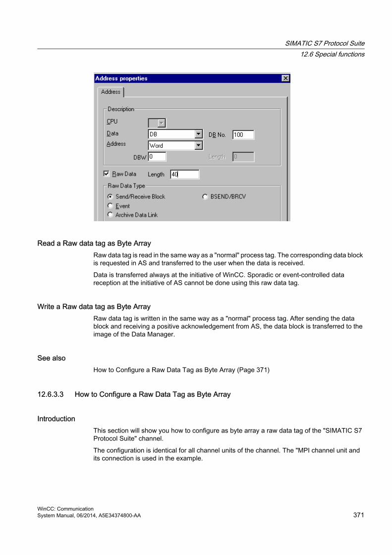
Read a Raw data tag as Byte ArrayRaw data tag is read in the same way as a "normal" process tag. The corresponding data block is requested in AS and transferred to the user when the data is received.
Data is transferred always at the initiative of WinCC. Sporadic or event-controlled data reception at the initiative of AS cannot be done using this raw data tag.
Write a Raw data tag as Byte ArrayRaw data tag is written in the same way as a "normal" process tag. After sending the data block and receiving a positive acknowledgement from AS, the data block is transferred to the image of the Data Manager.
See alsoHow to Configure a Raw Data Tag as Byte Array (Page 371)
12.6.3.3 How to Configure a Raw Data Tag as Byte Array
IntroductionThis section will show you how to configure as byte array a raw data tag of the "SIMATIC S7 Protocol Suite" channel.
The configuration is identical for all channel units of the channel. The "MPI channel unit and its connection is used in the example.
SIMATIC S7 Protocol Suite12.6 Special functions
WinCC: CommunicationSystem Manual, 06/2014, A5E34374800-AA 371
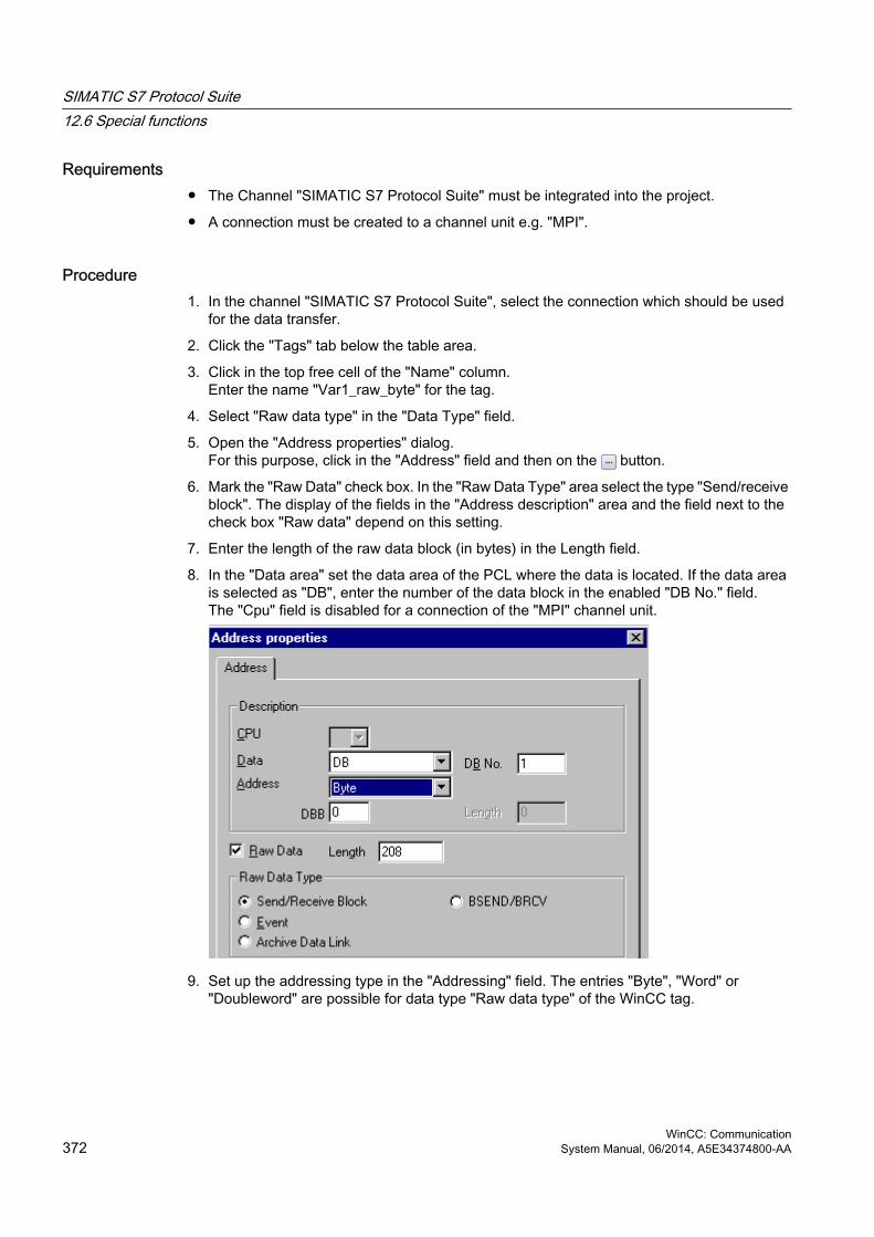
Requirements● The Channel "SIMATIC S7 Protocol Suite" must be integrated into the project.
● A connection must be created to a channel unit e.g. "MPI".
Procedure1. In the channel "SIMATIC S7 Protocol Suite", select the connection which should be used
for the data transfer.
2. Click the "Tags" tab below the table area.
3. Click in the top free cell of the "Name" column.Enter the name "Var1_raw_byte" for the tag.
4. Select "Raw data type" in the "Data Type" field.
5. Open the "Address properties" dialog.For this purpose, click in the "Address" field and then on the button.
6. Mark the "Raw Data" check box. In the "Raw Data Type" area select the type "Send/receive block". The display of the fields in the "Address description" area and the field next to the check box "Raw data" depend on this setting.
7. Enter the length of the raw data block (in bytes) in the Length field.
8. In the "Data area" set the data area of the PCL where the data is located. If the data area is selected as "DB", enter the number of the data block in the enabled "DB No." field.The "Cpu" field is disabled for a connection of the "MPI" channel unit.
9. Set up the addressing type in the "Addressing" field. The entries "Byte", "Word" or "Doubleword" are possible for data type "Raw data type" of the WinCC tag.
SIMATIC S7 Protocol Suite12.6 Special functions
WinCC: Communication372 System Manual, 06/2014, A5E34374800-AA

10.Enter the value of the start address in the underlying field. The label on the left field depends on the entry in the Data Area and Addressing field, for e.g. "DBB" for data area "DB" "Byte" for addressing type.
11.Click "OK" to close all open dialogs.
Note
The raw data length is limited to one transferable data block and must be fully transferable using a PDU (Protocol Data Unit). The maximum length of the data block that can be transferred using the communication driver depends on the PDU length negotiated while establishing the connection minus the header and additional information. The PDU lengths normally used in SIMATIC S7 thus result in the following maximum lengths:● S7-300: PDU length 240 Byte, max. data block length 208 Byte● S7-400: PDU length 480 Byte, max. data block length 448 Byte
Wrong length will cause the read/write job to be rejected with a display.
12.6.3.4 Raw data tag for BSEND/BRCV functions of S7 communication
Introduction Raw data tags for "BSEND/BRCV" functions are used for transferring user data blocks between WinCC and AS and handle only user data.
This raw data type can be used to access the "BSEND/BRCV" functions of S7 communication. The functions are available for the following automation systems:
● S7-400
● S7-300
– CPU319-3 PN/DP as of V2.5
– CPU317-2 PN/DP as of V2.6
– CPU315-2 PN/DP as of V3.1
Firmware version V3.x or higher is recommended for S7-300 controllers.
● WinAC RTX 2010
The initiative of data transfer always lies with the sending partner; hence "BSEND/BRCV" functions can also be used to implement event-controlled or sporadic data block transfers.
For resource reasons, it is advisable to keep the number of BSEND/BRCV raw data tags low.
Resource limitation for the use of S7 functions "AR_SEND" and "BSEND/BRCV" The maximum data volume that can be sent simultaneously using AR_SEND and/or BSEND/BRCV functions from AS to WinCC is limited:
SIMATIC S7 Protocol Suite12.6 Special functions
WinCC: CommunicationSystem Manual, 06/2014, A5E34374800-AA 373

● To 16 KB for the S7-400
● To 8 KB for the S7-300
Examples with the S7-400:
● 1x BSEND with a max. of 16 Kbytes
● 1x AR_SEND with 8 kBytes + 1x BSEND with 8 kBytes
● 1x AR_SEND with 10 Kbytes + 1x AR_SEND with 2 Kbytes + 1x BSEND with 4 Kbytes
Note
If the data block of a write job is transferred to AS and has not yet been deleted or fully deleted from the receiving buffer, then the next write job will be rejected with an error message. During such an error display, write jobs with R_ID > 0x8000 0000 are written to a connection-specific queue and the system tries to repeat the write job for 6 seconds.
The responsibility for time co-ordination for transfer rests with the user and needs to be noted as shorter time intervals for write jobs.
Configuring a PBK Connection for Using "BSEND/BRCV" functions"BSEND/BRCV" functions can only be used via a "hard-configured connection", a so-called PBK connection (programmed component communication). To configure a hard-configured connection, you must mention a connection resource (hex: 10 ... DF) in the connection parameters. This connection resource will be assigned by STEP 7 when the connection is configured within the PLC. The connection must be configured as passive connection end-point in the automation system.
A hard-configured connection can also be used to handle "normal" read and write jobs. If very large data areas are to be transferred via the connection, then the data blocks are transferred in multiple PDUs. For performance reasons, it would therefore be better to create a separate connection for "BSEND/BRCV" functions.
SIMATIC S7 Protocol Suite12.6 Special functions
WinCC: Communication374 System Manual, 06/2014, A5E34374800-AA

Configuring Raw data tag for BSEND/BRCV functionsRaw data tags for transferring "BSEND/BRCV" data blocks are configured as raw data of type "BSEND/BRCV" with a "R_ID". The data length is derived implicitly from the sent or received data volume.
"R_ID" ParameterFor the "BSEND/BRCV" functionality, you must specify a 32-bit long R_ID as hexadecimal number. The R_ID is assigned at the time of configuration in AS and is used for distinguishing multiple data block transfers over one connection. The send and receive calls are always notified with reference to this R_ID in the underlying communication sub-system (SIMATIC Device Drivers). A raw data tag is thus assigned to one unique R_ID.
Sending a "BSEND/BRCV" raw data tagSending a "BSEND/BRCV" raw data tag takes place in the same way as writing a "normal" process tag. After sending the data block and receiving a positive acknowledgment from AS, the data block is transferred to the image of the Data Manager.
Receiving a "BSEND/BRCV" raw data tag"BSEND/BRCV" raw data is sporadically sent to the channel on the initiative of the AS. Hence it is not possible to explicitly read S7 raw data tags.
The BSEND/BRCV mechanisms do not include any synchronization functions. If no user has logged in to receive the data during the start-up phase, the data blocks sent by AS will bounce
SIMATIC S7 Protocol Suite12.6 Special functions
WinCC: CommunicationSystem Manual, 06/2014, A5E34374800-AA 375

on the receiver side. Hence, the user has to take care of the synchronization and, for e.g., release the sending direction on the AS by setting a flag with a data word.
See alsoHow to Configure a Raw Data Tag for ""BSEND/BRCV" functions (Page 376)
12.6.3.5 How to Configure a Raw Data Tag for ""BSEND/BRCV" functions
IntroductionThis section will show you how to configure a raw data tag of the "SIMATIC S7 Protocol Suite" channel for "BSEND/BRCV" functions.
The configuration is identical for all channel units of the channel. The "MPI channel unit and its connection is used in the example.
Requirements● The Channel "SIMATIC S7 Protocol Suite" must be integrated into the project.
● A connection must be created to a channel unit e.g. "MPI".
Procedure1. In the channel "SIMATIC S7 Protocol Suite", select the connection which should be used
for the data transfer.
2. Click the "Tags" tab below the table area.
3. Click in the top free cell of the "Name" column.Enter the name "Var2_raw_bsend" for the tag.
4. Select "Raw data type" in the "Data Type" field.
5. Open the "Address properties" dialog.For this purpose, click in the "Address" field and then on the button.
6. Mark the "Raw Data" check box. In the "Raw Data Type" area select the type "BSEND/BRCV". The display of the fields of the "Address description" area is now deactivated.
SIMATIC S7 Protocol Suite12.6 Special functions
WinCC: Communication376 System Manual, 06/2014, A5E34374800-AA

7. Enter the hexadecimal value of the ID in the "R_ID" field. The R_ID is assigned in AS at the time of configuration
8. Close both of the dialogs by clicking the "OK" buttons.
12.6.4 Software Redundancy
12.6.4.1 Software Redundancy
IntroductionThe software redundancy offers a cost-effective option for monitoring the safety-related parts of the system that do not have time criticality through a redundant connection of two automation systems S7-300 or S7-400.
Note
The software redundancy of this channel does not have the same functions as the H Layer Redundancy of SIMATIC S7-400 H.
Configurations in AS and in WinCC are required for functioning.
SIMATIC S7 Protocol Suite12.6 Special functions
WinCC: CommunicationSystem Manual, 06/2014, A5E34374800-AA 377
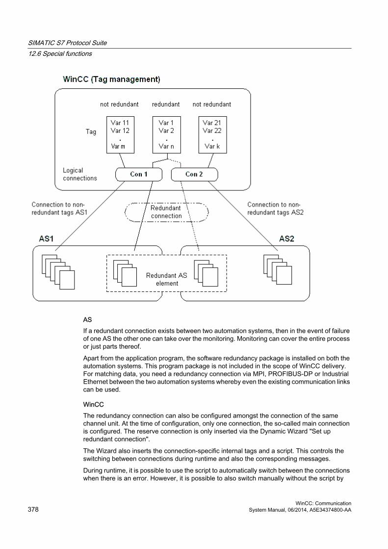
ASIf a redundant connection exists between two automation systems, then in the event of failure of one AS the other one can take over the monitoring. Monitoring can cover the entire process or just parts thereof.
Apart from the application program, the software redundancy package is installed on both the automation systems. This program package is not included in the scope of WinCC delivery. For matching data, you need a redundancy connection via MPI, PROFIBUS-DP or Industrial Ethernet between the two automation systems whereby even the existing communication links can be used.
WinCCThe redundancy connection can also be configured amongst the connection of the same channel unit. At the time of configuration, only one connection, the so-called main connection is configured. The reserve connection is only inserted via the Dynamic Wizard "Set up redundant connection".
The Wizard also inserts the connection-specific internal tags and a script. This controls the switching between connections during runtime and also the corresponding messages.
During runtime, it is possible to use the script to automatically switch between the connections when there is an error. However, it is possible to also switch manually without the script by
SIMATIC S7 Protocol Suite12.6 Special functions
WinCC: Communication378 System Manual, 06/2014, A5E34374800-AA

describing the connection-specific internal tags "@<connectionname>@ForceConnectionAddress".
For AS2, you need a second fixed configuration connection if data is to be used from the non-redundant part of AS2 in WinCC.
The use of software redundancy does not means that the hard configured connections can only be used for the redundancy. Each single connection can also be used without redundance.
See alsoHow to Clear a Software Redundancy in WinCC (Page 386)
How To Configure a Software Redundancy (Page 383)
Software Redundancy - Connection-specific internal tags (Page 379)
12.6.4.2 Software Redundancy - Connection-specific internal tags
IntroductionConnection-specific internal tags are used to control the redundant connections. These tags are setup using the Dynamic Wizard "Redundant Connection Configuration" and are gathered in a Tag Group called "@<connectionname>" in the associated connection.
These tags can be used to determine the connection status and to control the establishment of a connection. Thus, they can also be used to implement other applications, e.g. the addressing of multiple PLCs via a single connection. However, if these tags are to be used without the Software Redundancy package, they must be created manually.
Name FormatThe name of a connection-specific internal tag is composed of the name of the associated connection and an identifier.
"@<connectionname>@<identifier>"
The connection name is prefixed by a "@" to identify it as a system tag. The identifier is placed as a separator before the connection name.
Example: "@CPU_3@ConnectionState"
<connectionname> = CPU_3
<identifier> = ConnectionState
SIMATIC S7 Protocol Suite12.6 Special functions
WinCC: CommunicationSystem Manual, 06/2014, A5E34374800-AA 379

Note
Connection-specific internal tags are counted as external tags (eight external tags per connection).
WinCC's data manager only permits access to external tags when the associated connection is ready. The connection-specific internal tags can, however, be written and read regardless of the connection status.
In Runtime, the current values of some of the connection-specific internal tags may be called using the "WinCC Channel Diagnosis" tool. When the main connection is selected, the tags will be displayed in the "Counters" column. In addition, in WinCC Explorers' Tag Management, it is possible to display the tag's current value as a tooltip.
An Overview of the TagsThe following identifiers are available for the internal tags of Software Redundancy:
ConnectionState
Meaning Connection StatusThis tag can be used to find out the current connection status.
Type DWORDAccess ReadDefault value 0 = "faulty"Values 0 = Connection faulty
1 = Connection ready-to-use2 = Connection redundant (only in case of redundancy in H systems)
ConnectionError
Meaning Cause of faultThe tag contains a description of the cause for the fault. Default = 0, i.e. connection not yet established or without error. When establishing a connection, the tag is loaded with 0 (no error) again. The error code is interpreted in a channel-specific manner. The S7 channel passes the SIMATIC Device Driver's error code in this tag.
Type DWORDAccess ReadDefault value 0 = "No error"Values 0 = No error
<> 0 = S7 Error codes
SIMATIC S7 Protocol Suite12.6 Special functions
WinCC: Communication380 System Manual, 06/2014, A5E34374800-AA

ConnectionErrorString
Meaning Cause of fault as stringThe tag contains the reason for the connection error as string. The string is put out in the language currently selected. Default = ", i.e. connection not yet established or without error. In S7 channel, the following text is output in "English" regardless of the selected language.
Type TEXT8 [128]Access ReadDefault value "" = "No error"Values "No Error"
"Error hhhh" = Error hhhh has occurred (whereby hhhh = S7 error code hexadezimal)
ConnectionErrorCount
Meaning Counter for connection errorThe value of this tag is incremented by 1 every time there is a connection error. When there is an overflow, the counting starts back at 0.
Type DWORDAccess ReadDefault value 0
ConnectionEstablishMode
Meaning Connection Establish ModeThis tag can be used to set the automatic mode to establish a connection. If enabled, the S7 channel attempts to reestablish a failed connection at intervals of approx. 4 seconds. If the value in this tag = 0, there will be no attempt after every 4 seconds to reestablish the connection after a fault; rather it will remain disconnected.
Type DWORDAccess WriteDefault value 1 Values A Write to the tag brings about the following actions:
0 = Manual connection establish modeAction: Deactivate automatic connection establishment<>0 = Automatic connection establishment modeAction: Activate automatic connection establishment mode
SIMATIC S7 Protocol Suite12.6 Special functions
WinCC: CommunicationSystem Manual, 06/2014, A5E34374800-AA 381

ForceConnectionState
Meaning Preferred connection statusThis tag can be used to inform the channel about the preferred connection status. Usually this tag has the value 1, i.e. the channel attempts to establish the connection (at regular intervals of approx. 4 seconds, if applicable). If the value 0 is written to this tag, the channel interrupts the connection.
Type DWORDAccess WriteDefault value 1Values Any write to the tag has the following effects:
0 = preferred connection status: Connection brokenAction: if connection established, initiate disconnection1 = Preferred Connection Status: Connection brokenAction: if connection disconnected, initiate establishment of connection
ForceConnectionAddress
Meaning Select the connection addressThis tag defines which of the connection addresses is to be used to establish the connection.
Type DWORDAccess WriteDefault value 0 Values If ConnectionEstablishMode is set to "Automatic", the connection will be
setup automatically to the corresponding address.A Write to the tag brings about the following actions:0 = Connection via configured connection parametersAction: If @ForceConnectionAddress has been earlier set to 1, then initiate disconnection.1 = Connection via alternative connection parametersAction: If @ForceConnectionAddress previously on 0, then initiate disconnect.
SIMATIC S7 Protocol Suite12.6 Special functions
WinCC: Communication382 System Manual, 06/2014, A5E34374800-AA

AlternateConnectionAddress
Meaning Alternative Connection AddressIn this tag, you can enter the alternative connection address string. The string is the same as the one that will be displayed as the connection parameter in WinCC Explorer. The string is channel-specific. Upon system startup (Runtime), the configured address is entered here as default for the S7 channel. If an address has not been configured yet, the text "Illegal Address" is entered for the S7 channel.Example of address detail for a S7-AS with station address 3 via MPI: "MPI,3 0,,0,0,02"
Type TEXT8 [255]Access WriteDefault value "..." = "configured addressValues Writing to this tag gives rise to the following actions:
- If the address changes due to the write process, then the connection is disconnected fro the setting "Connection via alternative connection parameter".- If connection mode is set to "automatic", then the connection is automatically established with the address that has just been written.
12.6.4.3 How To Configure a Software Redundancy
IntroductionThis section describes how to configure the software redundancy for connections of the Channel "SIMATIC S7 Protocol Suite" in WinCC. The PLC must also be configured to use this function, but this will not be described in this document.
Requirements1. The Channel "SIMATIC S7 Protocol Suite" must be integrated into the project.
2. A connection must be created in one of this channel's channel-units to which a redundant connection should be configured.
Procedure1. In the computer's startup parameters, activate the "Global Script Runtime", "Alarm Logging
Runtime" and "Graphics Runtime" modules.For further information, please see "Checking startup parameters".
2. Load WinCC's system messages into Alarm Logging. These system messages include messages about software redundancy.You can find additional information about the topic under "Read WinCC system messages in Alarm Logging".
SIMATIC S7 Protocol Suite12.6 Special functions
WinCC: CommunicationSystem Manual, 06/2014, A5E34374800-AA 383

3. Open a picture in Graphics Designer. In the "Dynamic Wizard" window select the "System Functions" tab. Double-click to start the Dynamic Wizard "Setup Redundant Connection".
4. The procedure for using the wizard is described briefly in the "Welcome". Click "Next" to open the "Set Options" dialog.
5. Select the connection that should be used as the main connection and then click on "Next".The wizard will now create the connection-specific internal tags and will save them in a tag group "@" under the main connection.
SIMATIC S7 Protocol Suite12.6 Special functions
WinCC: Communication384 System Manual, 06/2014, A5E34374800-AA

6. Enter the address of the PLC to which the reserve connection should be established in the "Parameter" field.Mark the "Automatic Switching" check box to have the wizard generate a script for automatically switching connections. Click "Next"A graphic of the redundancy - showing a MPI connection to two PLCs - will appear in the picture:
7. All of the settings made will be displayed once more in the "Finished!" dialog. If you want to make any corrections, simply click on "Back". Click "Finish".The Wizard will now generate a script and save it under "@<connectionname>.pas" in the directory "C-Editor \ Actions \ Actions : <computername> of the Global Script Editor.
Note
In the following procedure, the "Setup redundant connection" wizard will be used. This wizard generates - when Step 6 is completed - the connection-specific internal variables. If the wizard is canceled at this point or the procedure is not completed by clicking on "Finish", these tags will remain unchanged.
See alsoHow To Load WinCC's system messages into Alarm Logging (Page 387)
How to Check the WinCC Startup Parameters (Page 386)
SIMATIC S7 Protocol Suite12.6 Special functions
WinCC: CommunicationSystem Manual, 06/2014, A5E34374800-AA 385

12.6.4.4 How to Clear a Software Redundancy in WinCC
IntroductionThis section describes how to delete the software redundancy for connections of the Channel "SIMATIC S7 Protocol Suite" in WinCC. The PLC must also be configured to use this function to return to non-redundant connections, but this is not described in this document.
Requirements● The WinCC project must be deactivated.
ProcedureA software redundancy is deleted in two steps:
● Delete the tag group "@<computername" including its tags in "Tag Management".
● Delete the script "@<connectionname>.pas" in "Global Script".
Procedure1. In the Tag Management, select the connection that should be configured as the main
connection for the software redundancy. It contains a tag group "@<connectionname" with the software redundancy's connection-specific internal tags. Delete this tag group.
2. Delete the script for the Action "@<connectionname>.pas". To do this, open the C-Editor in "Global Script". Several subdirectories will be displayed.
3. Select the "Actions \ Action : " directory. <computername>". In the data window, delete the script "@<connectionsname>.pas" for the "Actions" type.
4. Close the "Global Script" editor.
12.6.4.5 How to Check the WinCC Startup Parameters
Procedure1. In WinCC Explorer, select "Computer".
2. Open the shortcut menu and select "Properties".
3. The "Computer List Properties" dialog is opened. Click the "Properties" button.
4. The "Computer Properties" dialog is opened.
5. Click the "Startup" tab and check the entries. If necessary, activate or deactivate Runtime modules or add other applications to the startup list.
6. Close the open dialogs.
SIMATIC S7 Protocol Suite12.6 Special functions
WinCC: Communication386 System Manual, 06/2014, A5E34374800-AA

12.6.4.6 How To Load WinCC's system messages into Alarm Logging
IntroductionIn this section you will see how you can load the WinCC system messages into the project.
Procedure1. Open Alarm Logging.
2. Select the "System Messages" node in the navigation area.
3. You can activate the "Used" option for system messages that you use either in the table area or in the Properties area.
4. Select the command "Update used" from the shortcut menu of the "System Messages" node.
12.6.4.7 Error codes during connection disturbancesDocumentation of Error Codes
SIMATIC S7 Protocol Suite12.6 Special functions
WinCC: CommunicationSystem Manual, 06/2014, A5E34374800-AA 387


SIMATIC S7-1200, S7-1500 Channel 1313.1 "SIMATIC S7-1200, S7-1500 Channel" channel
IntroductionThe "SIMATIC S7-1200, S7-1500 Channel" is used for communication between a WinCC station and the automation systems S7-1200 and S7-1500. The TCP/IP protocol is used for the communication.
Channel unitThe "SIMATIC S7-1200, S7-1500 Channel" comes with the "OMS+" channel unit.
Recommended communications processorsThe following communications processors are recommended for the communication of a WinCC station with the automation systems S7-1200 or S7-1500:
● CP 1612 A2
● CP 1613 A2
● CP 1623
● CP 1628
WinCC: CommunicationSystem Manual, 06/2014, A5E34374800-AA 389

13.2 Overview of the supported data types
IntroductionThe data type and the format adaptation to the data format in the automation system (AS) are specified when the tag is configured.
The table shows the data types supported by the channel and the use of type conversions.
Supported data types
Data Types Type conversionBinary tag NoSigned 8-bit value YesUnsigned 8-bit value YesSigned 16-bit value YesUnsigned 16-bit value YesSigned 32-bit value YesUnsigned 32-bit value YesFloating-point number 32-bit IEEE 754 YesFloating-point number 64-bit IEEE 754 YesText tag, 8-bit font NoText tag, 16-bit character set NoDate/time Yes
SIMATIC S7-1200, S7-1500 Channel13.2 Overview of the supported data types
WinCC: Communication390 System Manual, 06/2014, A5E34374800-AA
13.3 Configuring the channel
13.3.1 Configuration of the "SIMATIC S7-1200, S7-1500 Channel" channel
IntroductionWinCC needs a logical connection for communication of WinCC with the automation system. This section describes how to configure the "SIMATIC S7-1200, S7-1500 Channel".
When using the TCP/IP protocol, you must define the IP address of the automation system for the logical connection. The IP address consists of four numerical values, separated by dots. The numerical values must be within the range "0-255".
NoteTimeout Behavior
Interrupted connections are not detected immediately when using the TCP/IP protocol. The check-back message can take up to a minute.
Configuring the tagsFor a connection between WinCC and the automation system via the "SIMATIC S7-1200, S7-1500 Channel", tags of different data types can be created in WinCC.
The configuration of the tags differs by the addressing of the data area in the automation system.
Note
You can only change the configuration of the automation system in the TIA Portal.
13.3.2 How to configure a connection
IntroductionThe following steps are required for configuring the "SIMATIC S7-1200, S7-1500 Channel":
1. Configuring a connection
2. Configuring tags
SIMATIC S7-1200, S7-1500 Channel13.3 Configuring the channel
WinCC: CommunicationSystem Manual, 06/2014, A5E34374800-AA 391

Requirements● The communication driver for "SIMATIC S7-1200, S7-1500 Channel" is installed and
integrated into the project.
● The SIMATIC project is configured and is available in the automation system.
Procedure1. Open the menu structure for the "SIMATIC S7-1200, S7-1500 Channel" communication
driver in the "Tag Management" editor of the WinCC Explorer.
2. Select the entry "New connection" from the shortcut menu of the channel unit "OMS+".
3. Enter the name of the connection.
4. Select the entry "Connection parameters" from the shortcut menu of the connection.The "New Connection" dialog opens.
5. Enter the IP address of the automation system.
6. Select an "Access point".
7. Select an automation system from the "product family".
8. If you want to use password protection, click "Options".
9. Enter the password for access protection.
10.Close both of the dialogs by clicking the "OK" button.
13.3.3 How to configure a tag without optimized block access
IntroductionThis section shows you how to configure a tag in WinCC without optimized block access to the address area in the automation system.
Requirement● The property "Optimized block access" is deactivated for the data block in the TIA Portal.
● The "SIMATIC S7-1200, S7-1500 Channel" must be integrated into the project.
● A connection must be created in the "OMS+" channel unit.
Procedure1. Select the required connection.
2. Click the "Tags" tab below the table area.
3. Click in the top free cell of the "Name" column. Enter a name for the tag. Configure the following settings in the table area or on the right-hand side in the "Properties - Tags" data area.
SIMATIC S7-1200, S7-1500 Channel13.3 Configuring the channel
WinCC: Communication392 System Manual, 06/2014, A5E34374800-AA

4. Select one of the supported data types.
5. Click the button in the "Address" column.
6. Enter the tag address.
7. Select the "Quality code" check box if the tag is with quality code and you wish to use it in WinCC. The code must also exist in the automation system. The check box can only be activated if the "DB" data area is selected.
8. Close the dialog by clicking "OK".
The figure below shows the tag management after tag configuration without optimized block access.
Notes on the configuration of an 8-bit text tagFor an 8-bit text tag in the "SIMATIC S7-1200, S7-1500 Channel", WinCC only supports the S7 string type consisting of a control word and the user data of the string:
● To configure an 8-bit text tag in WinCC, enter the address of the control word that exists in the automation system (AS) memory before the user data. The first byte of the control word contains the customized maximum length of the string, the second byte the actual length.
● With respect to creating the data structure in the automation system memory, you must note that the length of the 8-bit text tag configured in WinCC is extended by 2 bytes of the control word. If the data structures of the 8-bit text tags are created directly one after the other in the memory, the subsequent data is overwritten.
● While reading, the control word is read along with the user data and the current length is evaluated in the second byte. Only the user data according to the current length contained in the second control byte is transferred to the 8-bit text tags of WinCC.
● While writing, the actual length of the string is ascertained ("0" characters) and the control byte with the current length is sent to the automation system along with the user data.
SIMATIC S7-1200, S7-1500 Channel13.3 Configuring the channel
WinCC: CommunicationSystem Manual, 06/2014, A5E34374800-AA 393

13.3.4 How to configure a tag with optimized block access
IntroductionThis section shows you how to configure a tag in WinCC with optimized block access to the address area in the automation system.
Requirement● The property "Optimized block access" is activated for the data block in the TIA Portal.
● The "SIMATIC S7-1200, S7-1500 Channel" must be integrated into the project.
● A connection must be created in the "OMS+" channel unit.
● The connection must be established in Runtime.
SIMATIC S7-1200, S7-1500 Channel13.3 Configuring the channel
WinCC: Communication394 System Manual, 06/2014, A5E34374800-AA

Procedure1. Select the required connection.
2. Select "AS Symbols > Read from AS" from the shortcut menu.All available controller data are loaded into the "AS Symbols" tab in the table area.
3. The AS symbols are not automatically included in tag management. To transfer the required AS symbols to the "Tags" tab, activate the respective check box in the "Access" column.The selected tags are now available in the tag management.
SIMATIC S7-1200, S7-1500 Channel13.3 Configuring the channel
WinCC: CommunicationSystem Manual, 06/2014, A5E34374800-AA 395

How to edit AS symbols without controller connectionYou can configure the controller offline without being connected to it. To do so, you save the loaded AS symbols in a file.
1. Select the required connection.
2. Select "AS Symbols > Save to file" from the shortcut menu of the connection.
You can then load the AS symbols to the tag management in the offline project.
1. Select the required connection.
2. Select "AS Symbols > Load from file" from the shortcut menu of the connection.
SIMATIC S7-1200, S7-1500 Channel13.3 Configuring the channel
WinCC: Communication396 System Manual, 06/2014, A5E34374800-AA

SIMATIC TI Ethernet Layer 4 1414.1 WinCC channel "SIMATIC TI Ethernet Layer 4"
IntroductionThe communication driver "SIMATIC TI Ethernet Layer 4" handles the link between a WinCC station and a SIMATIC TI505 automation system via Industrial Ethernet. The communication is handled with the ISO transport protocol.
This chapter describes
● how to configure the data transfer with the "SIMATIC TI Ethernet Layer 4" channel.
● how to configure a connection and a tag.
Channel unitsIT has two channel units to run a maximum of two CP 1613. The functionality of the channel unit is identical. They differ only in the logical device names of the two CP 1613.
The logical device name can be changed via the system parameters of the channel unit. Here, it is also possible to set the parameters for the ISO transport protocol.
The following application capabilities exist:
● Channel unit 505 Ethernet (CP 1413-1) for the communication modules for SIMATIC Industrial Ethernet (e.g. CP 1613).
● Channel unit 505 Ethernet (CP 1413-2) for the communication modules for SIMATIC Industrial Ethernet (e.g. CP 1613).
WinCC: CommunicationSystem Manual, 06/2014, A5E34374800-AA 397

14.2 Data type of the tags
IntroductionDefine the required tags for a logical connection. From the WinCC viewpoint, you can access the following data types:
● Binary tag
● Unsigned 8 bit value (is only supported by VMS addressing)
● Signed 8 bit value (is only supported by VMS addressing)
● Unsigned 16-bit value
● Signed 16-bit value
● Unsigned 32-bit value
● Signed 32-bit value
● Floating-point number 32-bit IEEE 754
● Raw data type
SIMATIC TI Ethernet Layer 414.2 Data type of the tags
WinCC: Communication398 System Manual, 06/2014, A5E34374800-AA

14.3 Configuring the Channel
14.3.1 Configuring the channel "SIMATIC TI Ethernet Layer 4"
IntroductionThe following steps are required for configuring the channel "SIMATIC TI Ethernet Layer 4".
14.3.2 How to configure the connection
IntroductionThe process connection via Industrial Ethernet is possible with the SIMATIC TI505 automation system. Communication module CP 1434 TF is used in the automation system. The communication is handled with the ISO transport protocol.
The communication module CP 1613 is used in the WinCC system. Because communication takes place via the ISO transport protocol, it is not necessary to configure the logical connection in the local database.
For a logical connection, WinCC establishes one connection in the transport layer for reading (READ) and one for writing (WRITE). Only if both connections are established is the logical connection also indicated as being established.
Parameters for the READ functionWhen configuring the connection, parameters are defined for the READ function in WinCC. These are independent of the request used in the SIMATIC TI.
WinCC side SIMATIC TI sideFETCH-Active(Request "READ-Active")
READ-Passive(Request "READ-Passive")
FETCH-Passive(Request "WRITE-Passive")
WRITE-Active(Request "WRITE-Active")
Parameters "Own TSAP-ID" and "External TSAP-ID" for the WRITE function
WinCC side SIMATIC TI sideRequest "WRITE Active" Request "WRITE Passive"
SIMATIC TI Ethernet Layer 414.3 Configuring the Channel
WinCC: CommunicationSystem Manual, 06/2014, A5E34374800-AA 399

Procedure1. Select the required connection and select "Connection parameters" from the shortcut menu.
The "Connection properties" dialog opens.
2. Enter the station address of the SIMATIC TI on the industrial Ethernet bus in the field "Ethernet Address".
3. Now, define the parameters for the READ function in the WinCC system. These are independent of the request used in the SIMATIC TI.
4. Then, enter the value in the allocated field "Own TSAP-ID" that was configured in the "Remote parameter" area as "TSAP" while configuring the CP 1434 TF.
5. Now, enter the value in the allocated field "External TSAP-ID" that was configured in the "Local parameter" as "TSAP" while configuring the CP1434 TF.
6. Define the parameters "Own TSAP-ID" and "External TSAP-ID" for the WRITE function accordingly.
SIMATIC TI Ethernet Layer 414.3 Configuring the Channel
WinCC: Communication400 System Manual, 06/2014, A5E34374800-AA

14.3.3 Configuring the tags
14.3.3.1 Configuring the tags
IntroductionFor a connection between WinCC and the AS via channel "SIMATIC TI Ethernet Layer 4", tags of different data types can be created in WinCC. The following describes how to configure a tag of these data types.
14.3.3.2 How to configure the address of a tag
IntroductionThe tag address is entered according to the address structure of the SIMATIC TI505.
Procedure1. Select the tag
2. Select the desired data type in the "Data Type" field.
3. If it is a "Binary" or "8-Bit" tag, the "Bit/Byte tag" option is available in the "Properties" area. Tick the corresponding check box "Access a Bit/Byte", if data should be written to the AS memory.
SIMATIC TI Ethernet Layer 414.3 Configuring the Channel
WinCC: CommunicationSystem Manual, 06/2014, A5E34374800-AA 401

4. Open the "Address properties" dialog.For this purpose, click in the "Address" field and then on the button.
5. Select the location of the tag in the automation system in the "Address type" field. Depending the selected address type, more definitions have to be made (e.g. "V-tag memory" for address type in the "Data element" field).
6. In the field "Read-Only Tag", you can specify that the tag cannot be written by WinCC.
Note
Structure tags are not supported.
A description of address types may be found in the SIMATIC TI505 Technical Documentation.
Write access to memory areas in the AS can only performed bit-wise or byte-wise in channel "TI Ethernet Layer 4". When using binary and "8 Bit" tags, dialog "Bit-Byte-tag" is opened in addition to dialog "Address properties" and this can be used to define write access to individual bits or bytes. For this purpose, the addressed memory area is read from the AS for every single write request and the corresponding bits and/or bytes are modified. Afterwards, the data is written back to the AS's memory.
Note
Changes that have been made by the AS in a read data area are overwritten when writing back into the data area.
Depending on the type of tag, you can access the memory in the AS bit-wise or byte-wise.
SIMATIC TI Ethernet Layer 414.3 Configuring the Channel
WinCC: Communication402 System Manual, 06/2014, A5E34374800-AA

14.3.3.3 How to configure a tag with bit-wise access
IntroductionWrite access to memory areas in the AS can only performed bit-wise or byte-wise in channel "TI Ethernet Layer 4". When using binary and "8 Bit" tags, dialog "Bit-Byte-tag" is opened in addition to dialog "Address properties" and this can be used to define write access to individual bits or bytes. For this purpose, the addressed memory area is read from the AS for every single write request and the corresponding bits and/or bytes are modified. Afterwards, the data is written back to the AS's memory.
Note
Changes that have been made by the AS in a read data area are overwritten when writing back into the data area.
Procedure1. Select the tag.
2. Set the "Binary tag" data type in the "Data Type" field.
3. Open the "Bit/Byte tag" dialog.For this purpose, click in the "Address" field and then on the button.
4. Select the "Access to a bit" check box and define the addressing for the bit.
SIMATIC TI Ethernet Layer 414.3 Configuring the Channel
WinCC: CommunicationSystem Manual, 06/2014, A5E34374800-AA 403

5. Click the "Select" button. The "Address properties" dialog is opened.
6. Select the addressing type of the PLC memory in the "Address type" selection field.
7. From the list below, select the number of the element to be changed.
Note
A description of address types may be found in the SIMATIC TI505 Technical Documentation.
14.3.3.4 How to Configure a Tag with Byte by Byte Access
IntroductionWrite access to memory areas in the AS can only performed bit-wise or byte-wise in channel "TI Ethernet Layer 4". When using binary and "8 Bit" tags, dialog "Bit-Byte-tag" is opened in addition to dialog "Address properties" and this can be used to define write access to individual bits or bytes. For this purpose, the addressed memory area is read from the AS for every single write request and the corresponding bits and/or bytes are modified. Afterwards, the data is written back to the AS's memory.
Note
Changes that have been made by the AS in a read data area are overwritten when writing back into the data area.
Procedure1. Select the tag.
2. In the "Data Type" field, set the data type to "Unsigned 8-bit value" or "Signed 8-bit value".
3. Open the "Bit/Byte tag" dialog.For this purpose, click in the "Address" field and then on the button.
SIMATIC TI Ethernet Layer 414.3 Configuring the Channel
WinCC: Communication404 System Manual, 06/2014, A5E34374800-AA

4. Select the "Access to a byte" check box and define the addressing for the byte.
5. Click the "Select" button. The "Address properties" dialog is opened.
6. Select the addressing type of the PLC memory in the "Address type" selection field.
7. From the list below, select the number of the element to be changed.
Note
A description of address types may be found in the SIMATIC TI505 Technical Documentation.
14.3.4 System parameters
14.3.4.1 System parameters of the channel unit
IntroductionIf you require a configuration that deviates from the standard WinCC settings, you can make all the required changes using the "System parameters" dialog of the channel unit.
The following individual points can be changed:
SIMATIC TI Ethernet Layer 414.3 Configuring the Channel
WinCC: CommunicationSystem Manual, 06/2014, A5E34374800-AA 405

● the device name
● the transport parameter
Device NameCommunication between WinCC and the automation system takes place via logical device names. These names are assigned during the installation of the communication module and are unit-specific. The device name represents the logical device name. The logical device name is initially defined as "/CP_H1_1:/SCP" as default.
Transport ParameterSpecific settings for the channel unit are made in the transport parameters, e.g. PDU size, setup attempts, etc.
Note
The system parameters apply for all CPs in the AS.
14.3.4.2 How to Change the Device Name
IntroductionThe process connection via Industrial Ethernet is possible with the SIMATIC TI505 automation system. Communication module CP 1434 TF is used in the automation system. The communication is handled with the ISO transport protocol.
The communication module CP 1613 is used in the WinCC system. Because communication takes place via the ISO transport protocol, it is not necessary to configure the logical connection in the local database.
SIMATIC TI Ethernet Layer 414.3 Configuring the Channel
WinCC: Communication406 System Manual, 06/2014, A5E34374800-AA

Requirements● The channel "SIMATIC TI Ethernet Layer 4" must be integrated in the project.
Procedure1. Select the channel unit and open dialog window "System parameters" with the context
menu.
2. Select the "Device Name" Tab.
3. Now, you can select the logical device name shown in bold print with the mouse and change it with a mouse click in the name field. The logical device name is defined as "/CP_H1_1:/SCP" as default during the hardware driver installation. Only if you have defined another name there, which is not recommended, will you have to change the device name here as well.
14.3.4.3 How to change the transport parameter
IntroductionThe process connection via Industrial Ethernet is possible with the SIMATIC TI505 automation system. Communication module CP 1434 TF is used in the automation system. The communication is handled with the ISO transport protocol.
SIMATIC TI Ethernet Layer 414.3 Configuring the Channel
WinCC: CommunicationSystem Manual, 06/2014, A5E34374800-AA 407

The communication module CP 1613 is used in the WinCC system. Because communication takes place via the ISO transport protocol, it is not necessary to configure the logical connection in the local database.
Requirements● The channel "SIMATIC TI Ethernet Layer 4" must be integrated in the project.
Procedure1. Select the channel unit and open dialog window "System parameters" with the context
menu.
2. Select the "Transport parameter" tab.
3. Set the value for "PDU size" to the value that was configured on the CP 1434 TF.
4. Define how often a connection establishment should be attempted in the "Setup attempt" filed.
5. Select "Infinite" in the "Duration of Send Repetitions" area.
6. Enter value 30 in the "Acknowledgement time" field so that you are informed of the tag status after 30 seconds at the most, if the communication partner has not responded within this time (e.g. AS in "Stop" status).
SIMATIC TI Ethernet Layer 414.3 Configuring the Channel
WinCC: Communication408 System Manual, 06/2014, A5E34374800-AA

SIMATIC TI Serial 1515.1 WinCC channel "SIMATIC TI Serial"
IntroductionThe communication driver "SIMATIC TI Serial" is used for establishing a serial link between WinCC station and an SIMATIC TI505 automation device.
This chapter describes
● how to configure the data transfer with the "SIMATIC TI Serial" channel.
● how to configure a connection and a tag.
Channel unitsThe communication driver has one channel unit for controlling a COM port for the serial connection.
The following capability is available:
● Channel unit "505 Serial Unit #1" for serial communication, either via the TBP protocol or the NITP protocol.
Note
It is possible to run more than one logical connections (with different COM ports) through one channel unit.
WinCC: CommunicationSystem Manual, 06/2014, A5E34374800-AA 409

15.2 Data type of the tags
IntroductionDefine the required tags for a logical connection. From the WinCC viewpoint, you can access the following data types:
● Binary tag
● Unsigned 8 bit value (is only supported by VMS addressing)
● Signed 8 bit value (is only supported by VMS addressing)
● Unsigned 16-bit value
● Signed 16-bit value
● Unsigned 32-bit value
● Signed 32-bit value
● Floating-point number 32-bit IEEE 754
● Raw data type
SIMATIC TI Serial15.2 Data type of the tags
WinCC: Communication410 System Manual, 06/2014, A5E34374800-AA

15.3 Configuring the Channel
15.3.1 Configuring the "SIMATIC TI Serial" channel
IntroductionThe following steps are required for configuring the channel "SIMATIC TI Serial".
15.3.2 How to configure the connection
IntroductionThe process connection using a serial connection is possible with the SIMATIC TI505 automation system. The serial interface on the CPU module is used in the automation system.
No additional communication module is required in WinCC. Communication can take place by means of the default COM ports available on the system.
SIMATIC TI Serial15.3 Configuring the Channel
WinCC: CommunicationSystem Manual, 06/2014, A5E34374800-AA 411

Procedure1. Select the required connection and select "Connection parameters" from the shortcut menu.
The "Connection properties" dialog opens.
2. Select the communications interface (e.g. COM1, COM2 or a configured port) for the serial link in the "Serial port" field.
3. Select the field "Detect automatically" when the data transfer speed and the protocol used by the PLC are required to be detected automatically by the channel unit.
4. Set the data transfer rate and the protocol being used in the fields "Baud rate" and "Protocol".
5. By selecting the field "Optimized Requests," you can optimize data transfer to transfer several tags with one request.
6. If you select the "Deactivate connection" field, the logical connection is deactivated. This is often a good idea during commissioning to temporarily deactivate the connection.
SIMATIC TI Serial15.3 Configuring the Channel
WinCC: Communication412 System Manual, 06/2014, A5E34374800-AA

15.3.3 Configuring the tags
15.3.3.1 Configuring the tags
IntroductionFor a connection between WinCC and the PLC via channel "SIMATIC TI Serial", tags of different data types can be created within WinCC. This is described in the following section.
15.3.3.2 How to configure the address of a tag
IntroductionThe tag address is entered according to the address structure of the SIMATIC TI505.
Procedure1. Select the tag.
2. Set the required data type in the "Data Type" field (e.g. signed 16-bit value).
3. If it is a "Binary" or "8-Bit" tag, the "Bit/Byte tag" option is available in the "Properties" area. Tick the corresponding check box "Access a Bit/Byte", if data should be written to the AS memory.
4. Open the "Address properties" dialog.For this purpose, click in the "Address" field and then on the button.
SIMATIC TI Serial15.3 Configuring the Channel
WinCC: CommunicationSystem Manual, 06/2014, A5E34374800-AA 413

5. Select the location of the tag in the automation system in the "Address type" field. Depending the selected address type, more definitions have to be made (e.g. "V-tag memory" for address type in the "Data Element Number" field).
6. In the field "Read-Only Tag", you can specify that the tag cannot be written by WinCC.
Note
Structure tags are supported in address areas V, K, X, Y and C.
A description of address types may be found in the SIMATIC TI505 Technical Documentation.
Write access to memory areas in the AS can only performed bit-wise or word-wise in channel "TI Serial". When using binary and "8 Bit" tags, dialog "Bit-Byte-tag" is opened in addition to dialog "Address properties" and this can be used to define write access to individual bits or bytes. For this purpose, the addressed memory area is read from the AS for every single write request and the corresponding bits and/or bytes are modified. Afterwards, the data is written back to the AS's memory.
Depending on the type of tag, you can access the memory in the AS bit-wise or byte-wise.
15.3.3.3 How to configure a tag with bit-wise access
IntroductionWrite access to memory areas in the AS can only performed bit-wise or byte-wise in channel "SIMATIC TI Serial". When using binary and "8 Bit" tags, dialog "Bit-Byte-tag" is opened in addition to dialog "Address properties" and this can be used to define write access to individual bits or bytes. For this purpose, the addressed memory area is read from the AS for every single write request and the corresponding bits and/or bytes are modified. Afterwards, the data is written back to the AS's memory.
Note
Changes that have been made by the AS in a read data area are overwritten when writing back into the data area.
Procedure1. Select the tag.
2. Set the "Binary tag" data type in the "Data Type" field.
3. Open the "Bit/Byte tag" dialog.For this purpose, click in the "Address" field and then on the button.
SIMATIC TI Serial15.3 Configuring the Channel
WinCC: Communication414 System Manual, 06/2014, A5E34374800-AA

4. Select the "Access to a bit" check box and define the addressing for the bit.
5. Click the "Select" button. The "Address properties" dialog is opened.
6. Select the addressing type of the PLC memory in the selection field.
7. Select the number of bit to be changed in the selection field.
Note
With the S5, flags, inputs and outputs can be addressed byte by byte; data blocks (DB, DX) are addressed word by word.
15.3.3.4 How to Configure a Tag with Byte by Byte Access
IntroductionWrite access to memory areas in the AS can only performed bit-wise or byte-wise in channel "SIMATIC TI Serial". When using binary and "8 Bit" tags, dialog "Bit-Byte-tag" is opened in addition to dialog "Address properties" and this can be used to define write access to individual bits or bytes. For this purpose, the addressed memory area is read from the AS for every single
SIMATIC TI Serial15.3 Configuring the Channel
WinCC: CommunicationSystem Manual, 06/2014, A5E34374800-AA 415

write request and the corresponding bits and/or bytes are modified. Afterwards, the data is written back to the AS's memory.
Note
Changes that have been made by the AS in a read data area are overwritten when writing back into the data area.
Procedure1. Select the tag.
2. In the "Data Type" field, set the data type to "Unsigned 8-bit value" or "Signed 8-bit value".
3. Open the "Bit/Byte tag" dialog.For this purpose, click in the "Address" field and then on the button.
4. Select the "Access to a byte" check box and define the addressing for the byte.
5. Click the "Select" button. The "Address properties" dialog is opened.
6. Select the addressing type of the PLC memory in the selection field
7. Select the number of byte to be changed in the selection field.
SIMATIC TI Serial15.3 Configuring the Channel
WinCC: Communication416 System Manual, 06/2014, A5E34374800-AA

SIMOTION 1616.1 WinCC channel "SIMOTION"
Introduction The "SIMOTION" channel connects a WinCC station with a SIMOTION automation system. The connection is established via Industrial Ethernet using the TCP/IP protocol.
SIMOTION is a system platform for automation and drive solutions with an emphasis on motion control applications and technology tasks.
The SIMOTION modular system consists of the SIMOTION SCOUT Engineering System and a common runtime system for various hardware platforms.
Export the project from SIMOTION SCOUT to access the data of a SIMOTION SCOUT project.. Then create a WinCC project from the exported files with the Simotion Mapper.
You can configure certain changes to the configuration of the SIMOTION automation system, e.g. change an IP address, later in WinCC. Further changes must be configured in SIMOTION SCOUT, exported again and transferred with the Simotion Mapper.
Note
You must be familiar with the SIMOTION SCOUT Engineering System and the configuration of WinCC to configure the "SIMOTION" channel in WinCC.
WinCC: CommunicationSystem Manual, 06/2014, A5E34374800-AA 417

16.2 Overview of the supported data types
Introduction The data type and the format adaptation to the data format in the automation system are determined in the configuration of a tag.
The table shows the data types supported by the channel and the application of format adaptations.
Supported data types
Data Types Type conversionBinary tag NoSigned 8-bit value YesUnsigned 8-bit value YesSigned 16-bit value YesUnsigned 16-bit value YesSigned 32-bit value YesUnsigned 32-bit value YesFloating-point number 32-bit IEEE 754 YesText tag, 8-bit font NoRaw data type No
SIMOTION16.2 Overview of the supported data types
WinCC: Communication418 System Manual, 06/2014, A5E34374800-AA

16.3 Configuring the channel
16.3.1 Configuration of the "SIMOTION" channel
Introduction This chapter describes how to configure the "SIMOTION" channel.
Note
You must be familiar with the SIMOTION SCOUT Engineering System and the configuration of WinCC to configure the "SIMOTION" channel.
Proceed as follows to configure the "SIMOTION" channel:
1. Export the SIMOTION SCOUT project from SIMOTION SCOUT.
2. Create WinCC project with the Simotion Mapper.
3. Open WinCC project.
4. Configure system parameters.
Further information about the diagnosis of the channel, the connection and the tags can be found in the "Diagnosis 'SIMOTION' channel" chapter.
16.3.2 How to export a SIMOTION SCOUT project
Introduction This section describes how to export tags and message definitions from SIMOTION SCOUT.
Requirements:● You are familiar with the SIMOTION SCOUT Engineering System.
● You have access to the SIMOTION SCOUT project to be exported.
Procedure1. Open the SIMOTION SCOUT project to be exported in SIMOTION SCOUT.
2. Select "Export OPC Data" under "Tools."
SIMOTION16.3 Configuring the channel
WinCC: CommunicationSystem Manual, 06/2014, A5E34374800-AA 419

3. Select version "SIMATIC NET V6.4", the desired scope and at least the "OPC-Alarm/Event" option for the export.
Note
Simotion Mapper does not process other export versions than "SIMATIC NET V6.4".
4. Select the destination directory.
5. Select the communication interface.The project is exported.
6. Enter the routing information if you are using routing.
The SIMOTION SCOUT project is exported. The "OPC_Data.sti" and "OPC_AE.xml" files are saved in the destination directory.
16.3.3 How to create a WinCC project with Simotion Mapper
Introduction This section describes how to create a WinCC project from the exported SIMOTION SCOUT project with the Simotion Mapper.
Note
If a WinCC project was already created for an older version of the SIMOTION SCOUT project, only the SIMOTION parameters are changed in a transmission. All other configuration settings in the WinCC project (such as archiving) remain the same.
Requirements:● You have access to the export files "OPC_Data.sti" and "OPC_AE.xml" of the
SIMOTION SCOUT project.
● You have access rights to the WinCC installation directory.
Note
In the SIMOTION SCOUT programming environment, the tags to be exported can be filtered using the watch tables. Use the watch tables to keep the number of tags in the WinCC project low. More information on the watch tables can be found in the SIMOTION SCOUT online help.
Procedure1. Launch the "SimotionMapper.exe" program in the WinCC installation directory.
2. Click "Open". Navigate to the directory with the files "OPC_Data.sti" and "OPC_AE.xml".The data is read and displayed in Simotion Mapper.
SIMOTION16.3 Configuring the channel
WinCC: Communication420 System Manual, 06/2014, A5E34374800-AA

3. In the Simotion Mapper Explorer, select the groups and tags you need in your WinCC project.
4. Select "Create new WinCC project".
5. If you want to change the "WinCC connection name", click on the name displayed and enter the new name.
6. Specify the "First TA message number" for the technological alarm. The value must be selected in such a way that it does not lead to collisions with messages of other communication channels. The default value is 100.The Simotion Mapper creates one message and a total of six template messages for each Simotion connection starting from the number specified.
7. Click "Start mapping". Select the destination folder for the WinCC project.The WinCC project is created. The progress bar indicates the progress of the procedure.
8. Close Simotion Mapper.
The WinCC project is created and can now be opened and edited in WinCC.
Note
You may have to set the system parameters of the "SIMOTION" channel in WinCC to use the created WinCC project.
16.3.4 How to change a WinCC project with Simotion Mapper
Introduction This section describes how to add an exported SIMOTION SCOUT project to an existing WinCC project with the Simotion Mapper. In this way, you can use the same Simotion project several times in one WinCC project, for example.
Note
If a WinCC project was already created for an older version of the SIMOTION SCOUT project, only the SIMOTION parameters are changed in a transmission. All other configuration settings in the WinCC project (such as archiving) remain the same.
SIMOTION16.3 Configuring the channel
WinCC: CommunicationSystem Manual, 06/2014, A5E34374800-AA 421

Requirements:● You have access to the export files "OPC_Data.sti" and "OPC_AE.xml" of the
SIMOTION SCOUT project.
● You have access rights to the WinCC installation directory.
Note
In the SIMOTION SCOUT programming environment, the tags to be exported can be filtered using the watch tables. Use the watch tables to limit the number of tags in the WinCC project. More information on the watch tables can be found in the SIMOTION SCOUT online help.
Procedure1. Open the WinCC project to be edited.
2. Launch the "SimotionMapper.exe" program in the WinCC installation directory.
3. Click "Open". Navigate to the directory with the files "OPC_Data.sti" and "OPC_AE.xml".The data is read and displayed in Simotion Mapper.
4. In the Simotion Mapper Explorer, select the groups and tags you need in your WinCC project.
5. Select "Add to the open project".
6. If you want to re-add a group or tag that has already been created, you must change the "WinCC connection name" by clicking on the name displayed.
7. If you do not want to transfer any messages, groups or tags for a connection, unselect "WinCC connection name".
8. Specify whether tags should be overwritten.
9. Specify the "First TA message number" for the technological alarm. The value must be selected in such a way that it does not lead to collisions with messages of other communication channels. The default value is 100.The Simotion Mapper creates one message and a total of six template messages for each Simotion connection starting from the number specified.
Note
Please do change any "First TA message number" that has already been mapped. If you do, you may experience unpredictable message behavior.
10.Click "Start mapping". Select the destination folder for the WinCC project.The SIMOTION SCOUT project is added to the open WinCC project. The progress bar indicates the progress of the procedure.
11.Close Simotion Mapper.
The WinCC project was expanded by the SIMOTION SCOUT project and saved with your settings.
SIMOTION16.3 Configuring the channel
WinCC: Communication422 System Manual, 06/2014, A5E34374800-AA

16.3.5 How to change the connection parameters
Introduction In this section, you will learn how to change the connection parameters of the SIMOTION network address.
Note
Change only the connection parameters listed here. Do not create new connection for the "SIMOTION" channel. Incorrectly set connections may result in control errors in the PLC. Configure new connections according to the description in the section "Configuration of the "SIMOTION" channel (Page 419)".
Requirements● The SIMOTION communication driver is integrated in the WinCC project.
● A connection must be created in the "SIMOTION" channel unit.
Procedure1. Open the directory structure for the "SIMOTION" communication driver in the "Tag
Management" editor.
2. Select the entry "Connection parameters" from the shortcut menu of a connection of the "Simotion" channel unit.The "Connection parameters - SIMOTION" dialog opens.
SIMOTION16.3 Configuring the channel
WinCC: CommunicationSystem Manual, 06/2014, A5E34374800-AA 423

3. Change the connection parameters for the SIMOTION network address in the respective fields.
4. Close each open dialog box by clicking "OK."
16.3.6 How to change the tag address
Introduction This section describes how to change a tag address in the "SIMOTION" channel.
Note
You must have very good knowledge of the use of ANY pointers to change the tag address in the "SIMOTION" channel. No communication connection may be established if the tag address is entered incorrectly.
Requirements● The "SIMOTION" channel in integrated into the WinCC project.
● A connection with tags has been created in the "SIMOTION" channel unit.
Procedure1. Open the "SIMOTION tag address" dialog.
For this purpose, click in the "Address" field and then on the button.
2. Change the tag address.
SIMOTION16.3 Configuring the channel
WinCC: Communication424 System Manual, 06/2014, A5E34374800-AA

16.3.7 System parameter configuration
16.3.7.1 System Parameters of the Channel Unit
Introduction If you require a different configuration than the WinCC default settings, make these settings in the "System Parameters" dialog box.
You can change the following system parameters:
● Logical device name
● The channel uses cyclic read services in the AS
Logical device nameWinCC and the PLC communicate by means of logical device names that are assigned when the communications processor is installed in the PLC.
The channel uses cyclic read services in the ASThe PLC cyclic read services group the tags that are to be read cyclically into individual requests and transfer these to the PLC. The PLC sends the requested data the first time on receipt of the request and then again each time the cycle time elapses.
When cyclic read services are enabled, you can use the change-driven transfer function. If the PLC supports change-driven transfer, the data are then transferred only when values are changed.
16.3.7.2 How to Configure the System Parameters
Introduction This section shows how to configure the system parameters of the "SIMOTION" channel.
The "System Parameters" dialog comprises two tabs:
● "SIMOTION" tab
● "Unit" tab
Note
When the project is copied to another computer, the settings in the "Unit" tab are retained. The settings on the "SIMOTION" tab are deleted on the other hand.
SIMOTION16.3 Configuring the channel
WinCC: CommunicationSystem Manual, 06/2014, A5E34374800-AA 425

Requirements● The "SIMOTION" channel in integrated into the WinCC project.
Procedure1. Select the "SIMOTION" channel in the variable management. Open the "System
Parameters" dialog box in the shortcut menu of the "Simotion" channel unit.
2. Select the "SIMOTION" tab.
3. To enable cyclic reading of tags and change-driven transfer, select "by PLC" and "Change-driven transfer."
Note
The "cycle management", "lifebeat monitoring" and "stop monitoring" functions are not supported by the integrated SINAMICS servo control. The "SIMOTION" channel therefore ignores corresponding settings for connections to SINAMICS servo controls. The channel determines whether the AS supports the respective function when establishing the connection.
4. Select the "Lifebeat monitoring" function if required.Determine the interval in seconds for sending lifebeat monitoring messages. Determine the monitoring time in seconds for monitoring the response to a lifebeat monitoring message.
5. Enable "CPU Stop Monitoring" if you want WinCC to signal a fault in the communication when the SIMOTION CPU is in the stopped state.
SIMOTION16.3 Configuring the channel
WinCC: Communication426 System Manual, 06/2014, A5E34374800-AA

6. Select the "Unit" tab."S7ONLINE" is displayed as a default for "logical device name". You must change the device name if a different name was selected when installing the used communications processor.
7. To set the device name automatically at the start of runtime, select "Set automatically."
8. To give write jobs higher priority than read jobs during processing, select "Write with priority."
9. Close the dialog by clicking "OK."
Note
Setting changes only take effect after WinCC is restarted.
16.3.7.3 How to Change the Logical Device Name
Introduction WinCC and SIMOTION communicate through logical device names. These logical device names are assigned when the communications processor is installed.
Requirements● The "SIMOTION" channel in integrated into the project.
● A connection has been created in the "SIMOTION" channel unit.
SIMOTION16.3 Configuring the channel
WinCC: CommunicationSystem Manual, 06/2014, A5E34374800-AA 427

Procedure1. Select the SIMOTION channel in Tag Management.
2. Open the "System Parameters" dialog box in the shortcut menu.
3. Select the "Unit" tab.
4. Enter the device name in the "Logical device name" field. You can select an entry from the list or enter a new name.The device names are determined by the "Set PG/PC interface" tool. You call the tool in the system control. Only the currently set device name is displayed if it is not installed. If you specify a different logical device name, a message is displayed. Only enter a name if the communications processor being used on the target station is not installed on the configuring system.
5. Close the dialog by clicking "OK."
Note
Setting changes only take effect after WinCC is restarted.
SIMOTION16.3 Configuring the channel
WinCC: Communication428 System Manual, 06/2014, A5E34374800-AA

16.4 Diagnosis "SIMOTION" channel
16.4.1 Diagnosis possibilities of the "SIMOTION" channelThe following possibilities exist for the diagnosis and error detection of the "SIMOTION" channel and its tags.
Checking the Communication Processor ConfigurationAfter checking the access point, the communication processor can be tested with the "Set PG/PC interface" application. The communication processor can be checked under SIMATIC NET in the same way.
Checking the Configuration of the Connection and TagsThere may be errors in the configuration of the system and connection parameters. An incorrect tag addressing may also be responsible for wrong tag values.
Diagnosis of the Channel with "Channel Diagnosis" You can query the status of the channel and the connection in runtime with "Channel Diagnosis". Errors are displayed by "Error Codes".
Diagnosis of the Channel TagsYou can query the current value, the current quality code and the last change time of the tag in runtime in the tag management.
16.4.2 Description of Log File Entries
Introduction The channel enters important status changes and errors in the logfile. The entries support the analysis of communication faults.
Every entry in the file contains a date and time stamp with the following flag names and description.
Example of a logbook entry:2009-10-28 12:10:11,467 INFO Log starting ...
2009-10-28 12:10:11,483 INFO | LogFileName : D:\SIEMENS\WINCC\Diagnosis\Simotion_01.LOG
2009-10-28 12:10:11,483 INFO | LogFileCount : 3
SIMOTION16.4 Diagnosis "SIMOTION" channel
WinCC: CommunicationSystem Manual, 06/2014, A5E34374800-AA 429

2009-10-28 12:10:11,483 INFO | LogFileSize : 1400000
2009-10-28 12:10:11,483 INFO | TraceFlags : fa000000
2009-10-28 12:10:11,498 INFO SIMOTION channel DLL started!
2009-10-28 12:10:11,498 INFO SIMOTION channel with own cycle creation!
2009-10-28 12:10:11,967 INFO Connection "D445": StartRegisterEvVariable for dwVariableCount = 89
2009-10-28 12:10:11,967 INFO Connection "D445": RegisterEvVariable for Variable "@D445@CheckSum"!
...
2009-10-28 12:10:11,983 INFO Connection "D445": EndRegisterEvVariable
2009-10-28 12:10:12,436 INFO S7DOS release: @(#)TIS-Block Library DLL Version R8.0.0.0-REL-BASIS
2009-10-28 12:10:12,436 INFO S7DOS version: V8.0 / 0
2009-10-28 12:10:12,436 INFO SIMOTION version: V6.0 / Sep 15 2009 / 08:06:43
2009-10-28 12:10:12,436 INFO SIMOTION channel unit "Simotion" activated!
2009-10-28 12:10:12,451 ERROR Cannot connect to "SINAMICS_Integrated": Errorcode 0xFFDF 42C2!
2009-10-28 12:10:12,451 ERROR Cannot connect to "D445": Errorcode 0xFFDF 42C2!
Description of the Most Important Entries for the "INFO" Flag
Message text MeaningLogFileName : C:\ Siemens\ WinCC\ Diagnose\ "channel_name".LOG
Name of the log file with path
LogFileCount : "n" Number of log files of the channelLogFileSize : "x" Size of the individual log files in bytesTraceFlags : c4000000 Displays the flags used by the Trace function as a
hexadecimal numberSIMOTION channel DLL started! Start messageSIMOTION channel DLL terminated! End message
SIMOTION16.4 Diagnosis "SIMOTION" channel
WinCC: Communication430 System Manual, 06/2014, A5E34374800-AA

Description of the Most Important Entries for the "ERROR" Flag
Message text MeaningCannot connect to <connectionname>:Errorcode 0x0000 7<xxx>!
Communication errorCommunication to SIMOTION could not be established immediately after activating WinCC.<connectionname> = Name of connection<xxx> 1...fffThe channel has received all other error codes as the result of a function call of S7DOS, a lower layer or from the AS.
Connectionerror <nnn> <connectionname>:Errorcode 0x0000 7xxx!
Communication errorCommunication to SIMOTION could not be established after activating WinCC. The connection was broken.<nnn> = Number of connection terminations for this connection<connectionname> = Name of connection<xxx> 1...fffThe channel has received all other error codes as the result of a function call of S7DOS, a lower layer or from the AS.
Channel API error: errorstring Channel API errorThe channel passed the error string 'errorstring' to WinCC Explorer. The error string is displayed in an information box depending on the error relevance. See API error texts for a description of the error strings.
Max. count of API errors reached - API logbook deactivated
Channel API errorDepending on the error and function, errors can occur cyclically on the API. To avoid filling the logbook file with these error messages, a maximum of 32 messages are output for an API error.
Cannot write storage data! Cannot read storage data / use default dataStorage data illegal or destroyed / use default data!No storage data / use default data!
General Channel Error Messages
Devicename in unit "unitname" changed from "old devicename" to "new devicename"
Initialization message
Note
The error codes of the "SIMOTION" channel correspond to those of the "SIMATIC S7 Protocol Suite" channel. You will find the description of the error code in the "Error codes for connection fault" chapter in the help for the "SIMATIC S7 Protocol Suite" channel.
In addition, SIMOTION reports the error code 0x000 7301 if the consistency check failed. The reason for the error message is that the data exported from SIMOTION SCOUT for the AS entered checksum do not match the checksum in the connected device.
SIMOTION16.4 Diagnosis "SIMOTION" channel
WinCC: CommunicationSystem Manual, 06/2014, A5E34374800-AA 431


System Info 1717.1 "System Info" Channel
ContentsThe "System Info" channel is used to evaluate system information such as the time, date, disk capacity and provides functions such as timers and counters.
This chapter will show you
● configure the channel, connection and tags
● display system information in a process picture
● use system information to trigger and display a message
● display system information graphically
● display the system information from several servers in a multi-user system
WinCC: CommunicationSystem Manual, 06/2014, A5E34374800-AA 433

17.2 WinCC System Info Channel
PrincipleThe System Info channel is used to evaluate system information such as the time, date, disk capacity and provides functions such as timers and counters.
Possible applications are:
● Display of the time, date and day of the week in process pictures
● Triggering of events through evaluation of system information in scripts
● Display of the CPU load in a trend
● Display and monitoring of the available drive space on different servers of a client system
● Monitoring of the available disk capacity and triggering of a message
The channel requires no hardware, since it directly accesses the system information of the computer on which it has been installed. In order for the channel to function, a connection must be set up. Additional connections are possible, but not required for the proper operation.
For more information regarding the diagnosis of channels and tags, refer to "Communication Diagnostics".
NoteLicensing
The process tags required for the System Info channel need no licenses. Thus, the tags are not entered in the license count.User Rights
If you have no administrator rights, you must be a member of the superusers of the "System Monitor User" group in order to use the System Info channel.
Communication ManualThe communication manual contains additional information and extensive examples for the channel configuration. This manual is available for download on the Internet:
● http://support.automation.siemens.com/
Search by item number:
● A5E00391327
See alsoUse in Multi-User and Client Systems (Page 456)
How To Call Up and Evaluate System Information (Page 443)
How to Configure the System Info Channel (Page 442)
Differences to Other Software Components (Page 441)
System Info17.2 WinCC System Info Channel
WinCC: Communication434 System Manual, 06/2014, A5E34374800-AA

Overview of the Supported System Information (Page 436)
Diagnosis of Channels and Tags (Page 463)
System Info17.2 WinCC System Info Channel
WinCC: CommunicationSystem Manual, 06/2014, A5E34374800-AA 435

17.3 Overview of the Supported System Information
IntroductionIn the "Function" field in the "System Info" dialog, you can specify the system information to be assigned to a WinCC tag. The display format is set in the "Format" field.
System Info Channel Supported System Information - Overview
Function Data type Format PreviewDate Text tag
8-bit character setDD.MM.YYYYDD.MM.YYMM-DD-YYYYMM-DD-YYMM/DD/YY
21.10.199921.10.9910-21-199910-21-9910/21/99
Day Unsigned 16-bit value
DD 1...31
Month Unsigned 16-bit value
MM 1...12
Year Unsigned 16-bit value
YYYY 2000
System Info17.3 Overview of the Supported System Information
WinCC: Communication436 System Manual, 06/2014, A5E34374800-AA

Function Data type Format PreviewWeekday Unsigned
16-bit valueText tag8-bit character set
Text: 1 forMonday to7 for Sunday Text: Mon,Tue,Wed, Thu,Fri,Sat,Sun
1...7 Mon ... Sun
Time Text tag8-bit character set; length = 10 bytesLength = 12 bytes
HH:MM:SSHH:MMHH:MM AM,PMHH:MM:SS AM,PM
23:45:3723:4523:45 PM23:45:37 PM
Hour Unsigned 16-bit value
HH 0...23
Minute Unsigned 16-bit value
MM 0...59
Second Unsigned 16-bit value
SS 0...59
Milliseconds Unsigned 16-bit value
MSC 0...999
Counter Signed 32-bit value
ZZZZ 0...9999
CPU load Floating-point number 32-bit IEEE 754
Total load in %idle load in %process load in %
0...100%
Timer Signed 32-bit value
TTTT 0...9999
Free main memory Floating-point number 32-bit IEEE 754
Free capacity in kBFree in %Free in bytes
0...n kB0...100%0...n B
Freedisk capacity(local disks)
Floating-point number 32-bit IEEE 754
Free in MBFree in %
0...n MB0...100%
Printer monitoring Unsigned 32-bit value
Filled capacity of spooler disk Printer statusJob statusFree spooler diskarea in kBFree PRT_OUT-Disk areas in kBSize of spooler directory in kBSize of PRT_OUT directory in kB
0...n %
0...n0...n0...n kB
0...n kB
0...n kB
0...n kBStatus of swap file
Floating-point number 32-bit IEEE 754
Used in kBUsed in %Available in kB
0...n kB0...100%0...n kB
CounterThis function is useable for test purposes in scripts.
System Info17.3 Overview of the Supported System Information
WinCC: CommunicationSystem Manual, 06/2014, A5E34374800-AA 437

TimerWhen this function is selected, the "System Info" dialog is extended with fields "Limits from" and "to".
After every second, the timer is incremented or decremented. The direction in which the changes are made is determined by the starting and ending values in the fields "Limits from" and "to". If the start value is smaller than the end value, the timer is incremented. If the start value is greater than the end value, the timer is decremented.
If in Runtime, a value is entered in the I/O field linked to the timer, the start and current timer values is set to this value. Example: timer configured from 0 to 60. If "0" is written in Runtime, the timer is reset.
After the deactivation, the original start value is reapplied.
CPU loadFor the formats "Total load in %" and "Idle load in %" in connection with multiprocessor PCs enter the CPU number beginning with "0".For the format "Process load in %" enter the instance number, if there are several instances of a process.
Free disk capacityThe system can only determine the space available on a local hard disk or diskette.
Printer monitoringWith the "Printer status" and "Job status" formats the server name must be entered in the "Printer" field. The printers in use must support this status information to be able to use this system information.
In order to analyze the printer status, please observe the following:
● The port monitor is responsible for the transmission of the printer status to the spooler. Depending on the selected printer port, different port monitor DLLs are installed. From the port monitors supplied with Windows, only "TCPMON.DLL" is capable of transmitting the printer status using the TCP/IP port. "LOCALMON.DLL" using the LPT port does not communicate the printer status.
● The printer status is assessed only after a print job has been submitted, but not during polling of the status at the port.
In the case of the "Free PRT_OUT drive space" and "PRT_OUT Directory Size" formats, the channel automatically determines the path for the "Directory" field.
Error codes for the "Printer status" format
Status Error codePRINTER_STATUS_PAUSED 0x00000001PRINTER_STATUS_ERROR 0x00000002PRINTER_STATUS_PENDING_DELETION 0x00000004
System Info17.3 Overview of the Supported System Information
WinCC: Communication438 System Manual, 06/2014, A5E34374800-AA

Status Error codePRINTER_STATUS_PAPER_JAM 0x00000008PRINTER_STATUS_PAPER_OUT 0x00000010PRINTER_STATUS_MANUAL_FEED 0x00000020PRINTER_STATUS_PAPER_PROBLEM 0x00000040PRINTER_STATUS_OFFLINE 0x00000080PRINTER_STATUS_IO_ACTIVE 0x00000100PRINTER_STATUS_BUSY 0x00000200PRINTER_STATUS_PRINTING 0x00000400PRINTER_STATUS_OUTPUT_BIN_FULL 0x00000800PRINTER_STATUS_NOT_AVAILABLE 0x00001000PRINTER_STATUS_WAITING 0x00002000PRINTER_STATUS_PROCESSING 0x00004000PRINTER_STATUS_INITIALIZING 0x00008000PRINTER_STATUS_WARMING_UP 0x00010000PRINTER_STATUS_TONER_LOW 0x00020000PRINTER_STATUS_NO_TONER 0x00040000PRINTER_STATUS_PAGE_PUNT 0x00080000PRINTER_STATUS_USER_INTERVENTION 0x00100000PRINTER_STATUS_OUT_OF_MEMORY 0x00200000PRINTER_STATUS_DOOR_OPEN 0x00400000PRINTER_STATUS_SERVER_UNKNOWN 0x00800000PRINTER_STATUS_POWER_SAVE 0x01000000
Error codes for the "Job status" format
Status Error codeJOB_STATUS_PAUSED 0x00000001JOB_STATUS_ERROR 0x00000002JOB_STATUS_DELETING 0x00000004JOB_STATUS_SPOOLING 0x00000008JOB_STATUS_PRINTING 0x00000010JOB_STATUS_OFFLINE 0x00000020JOB_STATUS_PAPEROUT 0x00000040JOB_STATUS_PRINTED 0x00000080JOB_STATUS_DELETED 0x00000100JOB_STATUS_BLOCKED_DEVQ 0x00000200JOB_STATUS_USER_INTERVENTION 0x00000400JOB_STATUS_RESTART 0x00000800
System Info17.3 Overview of the Supported System Information
WinCC: CommunicationSystem Manual, 06/2014, A5E34374800-AA 439

Note
The error codes of the "Printer status" and "Job status" formats corresponds to the values in the Visual C-referenced file "Winspool.h" .
System Info17.3 Overview of the Supported System Information
WinCC: Communication440 System Manual, 06/2014, A5E34374800-AA

17.4 Differences to Other Software Components
IntroductionSome of the System Info channel system information can also be evaluated or displayed by WinCC using ActiveX controls.
Once fundamental difference to ActiveX controls can be seen in the fact that the System Info channel system information is assigned to a WinCC tag. The continued evaluation (e.g. of messages, limit values) can be carried out repeatedly and is then configured individually. The ActiveX controls are intended for use in the specified applications and may also be used for multi-user or client systems.
For the following system information, differences between the ActiveX control and the channel exist:
TimeThe ActiveX control "WinCC Digital/Analog Clock Control" is used to display the time in WinCC. This control also supports an analog display of the time. The control does not require the System Info channel even when if it is used in the process control system options. Using the control, it is possible to display a WinCC client's time in its process picture. This is not possible with the System Info channel, since this always displays the server's system time.
Free disk capacityThe ActiveX control "IX Diskspace" is supplied to display the disk space available in WinCC. This ActiveX control can also display the space available on network drives and supports other configuration options such as the setting of multiple limit values directly in the control.
System Info17.4 Differences to Other Software Components
WinCC: CommunicationSystem Manual, 06/2014, A5E34374800-AA 441

17.5 Configuring the Channel
17.5.1 How to Configure the System Info Channel
IntroductionThis section illustrates how to configure the System Info channel.
Procedure1. In the navigation area of the tag management, select the entry "Add new driver" in the
shortcut menu of node "Tag Management".
2. Select the "System Info" driver. The channel is created and the communication driver is displayed in the tag management.
3. Select the associated System Info channel unit and call up the shortcut menu. In this shortcut menu, select "New Connection".
4. Enter the name of the connection.
5. Click the "Tags" tab below the table area.
6. Click in the top free cell of the "Name" column.Enter the name for the tag.If you want to use examples for this channel, continue with the topic "How to Configure a Tag".
7. Select the desired data type in the "Data Type" field.
System Info17.5 Configuring the Channel
WinCC: Communication442 System Manual, 06/2014, A5E34374800-AA

17.6 Examples of Evaluating and Displaying System Information
17.6.1 How To Call Up and Evaluate System InformationThis section uses examples to illustrate how system information can be displayed and evaluated in a variety of ways.
See alsoHow to Display the Printer Status in a Status Display (Page 452)
How to Configure a Message Regarding Free Disk Capacity (Page 448)
How to Display the CPU Load in a Trend Window (Page 447)
How to Display the Free Disk Capacity in a Bar Graph (Page 446)
How to Display the Time in an I/O Field (Page 444)
How to Configure a Tag in the System Info Channel (Page 443)
17.6.2 How to Configure a Tag in the System Info Channel
IntroductionThis section illustrates how to configure tags in the System Info channel. These tags are used in the examples.
RequirementsInstall the "SystemInfo.chn" channel.
Table of the Data Types UsedThe table below shows the tag types and formats used in the System Info channel.
Example System Information Tag name Data type FormatI/O field Time Sysinfo_Time Text tag
8-bit character setHours: minutes:seconds(HH:MM:SS)
Bar,message
Free drivecapacity(drive: C)
Sysinfo_Drive_C Floating-point number 32-bit IEEE 754
0-100%(free in %)
Trends CPU load Sysinfo_CPU Floating-point number32-bit IEEE 754
0-100%(total load in %)
Printer status
Printer monitoring Sysinfo_Printerstate
Unsigned 32-bit value
0-n (hex)(printer status)
System Info17.6 Examples of Evaluating and Displaying System Information
WinCC: CommunicationSystem Manual, 06/2014, A5E34374800-AA 443

Procedure1. In the shortcut menu of the associated System Info channel unit, select the entry "New
Connection" and create a connection named "Testinfo".
2. Click the "Tags" tab below the table area.
3. Click in the top free cell of the "Name" column.Enter the name for the tag.
4. Open the "System Info" dialog.For this purpose, click in the "Address" field and then on the button.
5. In the "Data Type" field, set the tag's data type in accordance with the table.
6. Set the system information and display format in accordance with the information in the table.
7. Close the dialog.
See alsoHow to Configure a Message Regarding Free Disk Capacity (Page 448)
How to Configure the System Info Channel (Page 442)
How to Display the Printer Status in a Status Display (Page 452)
How to Display the CPU Load in a Trend Window (Page 447)
How to Display the Free Disk Capacity in a Bar Graph (Page 446)
How to Display the Time in an I/O Field (Page 444)
17.6.3 How to Display the Time in an I/O Field
RequirementsConfigure a "Sysinfo_Time" tag with data type "Text tag 8-bit character set". This tag must be assigned the "Time" system information with display format "HH:MM:SS".
System Info17.6 Examples of Evaluating and Displaying System Information
WinCC: Communication444 System Manual, 06/2014, A5E34374800-AA

Procedure1. Start Graphics Designer and open a picture.
2. Add an I/O field to the picture. Select the "I/O field" object from the object list under "Smart Objects". The "I/O Field Configuration" dialog is opened.
3. In the "Tag" field, enter the name "Sysinfo_Time".
4. Set the update to "1 s".
5. Set the field type to "Output". Close the dialog.
6. Click "Properties" in the I/O field's shortcut menu to open the "Object Properties" dialog.
7. On the "Properties" tab, select "Output/Input". Set the "Data Format" attribute to "String".
8. Close the dialog and save the picture.
9. Click the appropriate button in the Graphics Designer toolbar to activate Runtime.
Note
The update cycle should be chosen with careful consideration, as it affects the load on the computer. Therefore, updating a time display every 250 ms is detrimental to the system performance.
See alsoHow to Start Runtime (Page 455)
How to Insert an I/O Field (Page 455)
How to Configure a Tag in the System Info Channel (Page 443)
System Info17.6 Examples of Evaluating and Displaying System Information
WinCC: CommunicationSystem Manual, 06/2014, A5E34374800-AA 445

17.6.4 How to Display the Free Disk Capacity in a Bar Graph
RequirementsConfigure a tag "Sysinfo_Drive_C" with data type "Floating-point number 32-bit IEEE754". This tag must be assigned the "Free Disk Space" system information for drive "C" with display format "Free capacity in %".
Procedure1. Start Graphics Designer and open a picture.
2. Insert a bar graph into the picture. For this purpose, select the object "Bar" from "Smart Objects" in the object palette. The "Bar Configuration" dialog is opened.
3. In the "Tag" field, enter the name "Sysinfo_Drive_C".
4. Set the update to "5 s".
5. Set the maximum value to "100" and the minimum value to "0". Close the dialog.
6. Click on "Properties" in the bar graph shortcut menu to open the "Object Properties" dialog.
7. On the "Properties" tab, select "Axis". Set the attribute "Decimal Places" to "0".
8. Close the dialog and save the picture.
9. Click the appropriate button in the Graphics Designer toolbar to activate Runtime.
Note
The update cycle should be chosen with careful consideration, as it affects the load on the computer. Therefore, updating an available drive space display every second is detrimental to the system performance.
System Info17.6 Examples of Evaluating and Displaying System Information
WinCC: Communication446 System Manual, 06/2014, A5E34374800-AA

See alsoHow to Start Runtime (Page 455)
How to Insert a Bar Graph (Page 454)
How to Configure a Tag in the System Info Channel (Page 443)
17.6.5 How to Display the CPU Load in a Trend Window
RequirementsConfigure a tag named "Sysinfo_CPU" with data type "Floating-point number 32-bit IEEE754". This tag must be assigned the "CPU Load" system information with display format "Total load in %".
Procedure1. Start Graphics Designer and open a picture.
2. Insert a trend display into the picture. You can accomplish this by selecting the "WinCC Online Trend Control" object from the "Controls" object palette. The "Properties of WinCC Online Trend Control" dialog is opened.
3. On the "General" tab, enter the name "Trend1" in the "Window Title" field.
4. In the "Data Source" field, select "Online Tags".
5. Click the "Trends" tab and then the "Selection" button to open the "Tag Configuration" dialog.
System Info17.6 Examples of Evaluating and Displaying System Information
WinCC: CommunicationSystem Manual, 06/2014, A5E34374800-AA 447

6. Enter "Sysinfo_CPU" as the name of the tag and then select a cycle time of "2 s". Close the dialog.
7. Close the "Properties of WinCC Online Trend Control" dialog and save the picture.
8. Click the appropriate button in the Graphics Designer toolbar to activate Runtime.
Note
The update cycle should be chosen with careful consideration, as it affects the load on the computer. Therefore, updating a CPU load display every 500 ms is detrimental to the system performance.
See alsoHow to Start Runtime (Page 455)
How to Configure a Tag in the System Info Channel (Page 443)
17.6.6 How to Configure a Message Regarding Free Disk Capacity
RequirementsConfigure a tag "Sysinfo_Drive_C" with data type "Floating-point number 32-bit IEEE754". This tag must be assigned the "Free Disk Space" system information for drive "C" with display format "Free capacity in %".
System Info17.6 Examples of Evaluating and Displaying System Information
WinCC: Communication448 System Manual, 06/2014, A5E34374800-AA

Procedure1. Open the "Alarm Logging" editor and create a new message.
2. In the "Properties" area, define:
– the text "Memory space" as "Message text"
– the text "Hard disk" as "Point of error"
3. In the Alarm Logging navigation area, select the "Analog Alarm" node.
4. Create a new analog alarm for the tag "Sysinfo_Drive_C".
5. Activate the option "Shared message". In the "Message Number" field, enter the number of the newly created message.
System Info17.6 Examples of Evaluating and Displaying System Information
WinCC: CommunicationSystem Manual, 06/2014, A5E34374800-AA 449

6. Select "Analog Alarm" in the navigation window. Select the entry "Sysinfo_Drive_C" in the data window. Click "New" in the shortcut menu to open the "Properties" dialog. Click the radio button "Lower Limit" and enter the value "30" in the "Limit value or tag" field.
7. Close the dialog. Save and exit Alarm Logging.
See alsoHow to Configure a Tag in the System Info Channel (Page 443)
How to Display a Message regarding the Available Disk Capacity (Page 450)
17.6.7 How to Display a Message regarding the Available Disk Capacity
Requirements● A tag "Sysinfo_Drive_C" with data type "Floating-point number 32-bit IEEE754". The tag
must be assigned the "Free Disk Space" system information for drive "C" with the display format "Free mem in %".
● A message text and the lower limit value for the limit value monitoring of this tag.
● "Alarm Logging Runtime" must be set in the computer's startup parameters.
System Info17.6 Examples of Evaluating and Displaying System Information
WinCC: Communication450 System Manual, 06/2014, A5E34374800-AA

Procedure1. Start Graphics Designer and open a picture.
2. Insert a message window into the picture. Select the "WinCC Alarm Control" object from the "Controls" object palette and place it in the picture.Close the quick configuration dialog without making any further changes.
3. Double-click the inserted control to open the "WinCC Alarm Control Properties" dialog.
4. Select the "User Text Blocks" entry from the "Type" field on the "Message Blocks" tab. Under "Selection", select the check boxes "Message Text" and "Point of Error".
5. Click the "Message Line" tab. In the "Available Message Blocks" field, mark the entries "Message Text" and "Point of Error" and then click the "Right Arrow" button to transfer them to the "Elements of message line" field. Close the dialog.
6. Save the picture.
7. Click the appropriate button in the Graphics Designer toolbar to activate Runtime.
System Info17.6 Examples of Evaluating and Displaying System Information
WinCC: CommunicationSystem Manual, 06/2014, A5E34374800-AA 451

See alsoHow to Check the WinCC Startup Parameters (Page 454)
How to Start Runtime (Page 455)
How to Configure a Tag in the System Info Channel (Page 443)
17.6.8 How to Display the Printer Status in a Status Display
IntroductionThis example shows a possible evaluation of the "Printer monitoring" system information based on the "Printer status" display format. The printer or job status could also be evaluated by configuring messages that are triggered by single bits in the printer or job status.
Requirements● Configure a "Sysinfo_Printerstate" tag with data type "Unsigned 32-bit value". This tag must
be assigned to the "Printer monitoring" system information with the "Printer status" display format.
● The printers in use must support these status displays to be able to use this system information.
System Info17.6 Examples of Evaluating and Displaying System Information
WinCC: Communication452 System Manual, 06/2014, A5E34374800-AA

Procedure1. Start Graphics Designer and open a picture.
2. Insert a status display into the picture. Select the "Status display" object from the object palette under "Smart Objects". The "Status Display Configuration" dialog is opened.
3. In the "Tag" field, enter the name "Sysinfo_Printerstate".
4. Set the update to "1 s".
5. Select the value "0" in the "Status" column. Assign this status an icon from the "Picture Selection" area which, for example, represents a printer. Select the desired icon, drag it to the "0" line with the mouse and drop it in the "Basic Picture" column. If no picture or a picture other than the desired picture is shown in the "Picture Selection" area, a selection dialog can be opened by clicking the "Browse..." button.
6. If you wish you can add additional bit positions with the "Add" button and assign another picture to these statuses.
7. Close the dialog and save the picture.
8. Click the appropriate button in the Graphics Designer toolbar to activate Runtime.
System Info17.6 Examples of Evaluating and Displaying System Information
WinCC: CommunicationSystem Manual, 06/2014, A5E34374800-AA 453

In Runtime, a printer ready for use is displayed with the icon assigned the status "0" in step 5. No picture is shown if there is an error in the printer or if you have not run step 6. If you assigned icons to the other bit positions in step 6, they are shown accordingly.
Note
The update cycle should be chosen with careful consideration, as it affects the load on the computer. Therefore, updating a time display every 250 ms is detrimental to the system performance.
See alsoHow to Configure a Tag in the System Info Channel (Page 443)
How to Start Runtime (Page 455)
17.6.9 How to Check the WinCC Startup Parameters
Procedure1. In WinCC Explorer, select "Computer".
2. Open the shortcut menu and select "Properties".
3. The "Computer List Properties" dialog is opened. Click the "Properties" button.
4. The "Computer Properties" dialog is opened.
5. Click the "Startup" tab and check the entries. If necessary, activate or deactivate Runtime modules or add other applications to the startup list.
6. Close the open dialogs.
17.6.10 How to Insert a Bar Graph
Procedure1. Start Graphics Designer and open a picture.
2. In the "Standard" object palette under "Smart Objects", select the object "Bar".
3. Insert a bar graph into the picture. To do this, point the mouse on the location in the working area where you want the bar graph to be placed. While keeping the mouse button pressed, drag the object to the desired size.
4. After you release the mouse button, the "Bar Configuration" dialog is opened. In this dialog, enter the name of a WinCC tag and set the update specifications and limit. Additionally, you can use the "Bar Direction" to set the orientation of the displayed bar.
5. Close the dialog.
System Info17.6 Examples of Evaluating and Displaying System Information
WinCC: Communication454 System Manual, 06/2014, A5E34374800-AA

17.6.11 How to Insert an I/O Field
Procedure1. Start Graphics Designer and open a picture.
2. In the "Standard" object palette under "Smart Objects", select the object "I/O Field".
3. Insert the I/O field into the picture. To do this, position the mouse on the location in the working area where you want the I/O field to be placed. While keeping the mouse button pressed, drag the object to the desired size.
4. After you release the mouse button, the "I/O Field Configuration" dialog is opened. In this dialog, enter the name of a WinCC tag and set the update and field type settings. Additionally, you can also select the "Font" to be used to display the value.
5. Close the dialog.
17.6.12 How to Start Runtime
RequirementsA startup picture must be defined before Runtime is activated.
Procedure1. Save and close all files that may be open in an editor.
2. Select WinCC Explorer.
3. Activate the project by clicking the "Activate" button in the toolbar or by selecting "Activate" in the "File" menu.
System Info17.6 Examples of Evaluating and Displaying System Information
WinCC: CommunicationSystem Manual, 06/2014, A5E34374800-AA 455

17.7 Special Functions
17.7.1 Use in Multi-User and Client Systems
17.7.1.1 Use in Multi-User and Client Systems
IntroductionIn multi-user and client systems, the System Info channel can be used to process the system information from a server on a client system. In a client system, it is thus possible for a single WinCC client to monitor several servers.
See alsoMonitoring the system information of several servers on a WinCC client (Page 456)
17.7.2 Example of monitoring system information from multiple servers
17.7.2.1 Monitoring the system information of several servers on a WinCC client
IntroductionIn this example, two servers are monitored by a single WinCC client. The monitored system information such as available disk space and CPU load is displayed in a process picture on the WinCC client.
This requires the following configurations:
Configuration of first server
Configuration of second server
Import of tags on the WinCC client
Configuration of the process picture on the WinCC client
Activation of the project
RequirementsThe server and the WinCC client must be connected through a Windows network.
System Info17.7 Special Functions
WinCC: Communication456 System Manual, 06/2014, A5E34374800-AA

See alsoHow to Activate the Project (Page 461)
How to Configure the Process Picture on the WinCC Client (Page 460)
How to Import the Tags to the WinCC Client (Page 459)
How to Configure the Second Server (Page 458)
How to Configure the First Server (Page 457)
17.7.2.2 How to Configure the First Server
IntroductionThis section presents the configuration of the first server, which is necessary for this example.
1. Configure the tags of the "System Info" channel to display available drive space and CPU load.
2. Generation of a package.
Table of the Data Types UsedThe tag names and formats used in this "System Info" channel example are listed in the following table.
Tag Function Data type FormatSysvar_1_Drive_C
Free drivecapacity
Floating-point number32-bit IEEE 754
0-100% (free in %)
Sysvar_1_CPU CPU load Floating-point number32-bit IEEE 754
0-100% (total load in %)
Procedure1. Create a multi-user project named "Testinfo_1" on the first server. Install the "System Info"
driver in the project.
2. In the shortcut menu of the associated "System Info" channel unit, select the entry "New Connection" and create a connection named "Connection1".
3. Click the "Tags" tab below the table area.
4. Click in the top free cell of the "Name" column.Enter the name "Sysvar_1_Drive_C" for the tag.
5. Set the "Data Type" to "Floating-point number 32-bit IEEE 754".
6. Open the "System Info" dialog.For this purpose, click in the "Address" field and then on the button.
7. Set the "Function" field to "Available Drive Space", the "Drive" to "C" and "Format" to "Free capacity in %". Close the dialog.
System Info17.7 Special Functions
WinCC: CommunicationSystem Manual, 06/2014, A5E34374800-AA 457

8. Click in the top free cell of the "Name" column.Enter the name "Sysvar_1_CPU" for the tag.
9. Set the "Data Type" to "Floating-point number 32-bit IEEE 754".
10.Open the dialog "System Info".For this purpose, click in the "Address" field and then on the button.
11.Set the value in the "Function" field to "CPU Load" and the value in "Format" to "Total load in %". Close the dialog.
12.Create a package. Proceed by selecting "Server data" in the navigation window and opening the shortcut menu. Select the menu item "Create". Acknowledge the message stating that the package was created.
See alsoHow to Configure the Second Server (Page 458)
17.7.2.3 How to Configure the Second Server
IntroductionThis section presents the configuration of the second server, which is necessary for this example.
1. Configure the tags of the "System Info" channel to display available drive space and CPU load.
2. Generation of a package.
Table of the Data Types UsedThe tag names and formats used in this "System Info" channel example are listed in the following table.
Tag Function Data type FormatSysvar_2_Drive_C
Free drivecapacity
Floating-point number 32-bit IEEE 754
0-100% (free in %)
Sysvar_2_CPU CPU load Floating-point number 32-bit IEEE 754
0-100% (total load in %)
Procedure1. Create a multi-user project named "Testinfo_2" on the second server. Install the "System
Info" driver in the project.
2. In the shortcut menu for the associated "System Info" channel unit, select the entry "New Connection" and create a connection named "Connection2".
3. Click the "Tags" tab below the table area.
System Info17.7 Special Functions
WinCC: Communication458 System Manual, 06/2014, A5E34374800-AA

4. Click in the top free cell of the "Name" column.Enter the name "Sysvar_2_Drive_C" for the tag.
5. Set the "Data Type" to "Floating-point number 32-bit IEEE 754".
6. Open the "System Info" dialog.For this purpose, click in the "Address" field and then on the button.
7. Set the "Function" field to "Available Drive Space", the "Drive" to "C" and "Format" to "Free capacity in %". Close all open dialogs.
8. Click in the top free cell of the "Name" column.Enter "Sysvar_2_CPU" as the name of the tag.
9. In the connection shortcut menu, select "New Tag".
10.Set the "Data Type" to "Floating-point number 32-bit IEEE 754".
11.Open the dialog "System Info".For this purpose, click in the "Address" field and then on the button.
12.Set the value in the "Function" field to "CPU Load" and the value in "Format" to "Total load in %". Close all open dialogs.
13.Create a package. Proceed by selecting "Server data" in the navigation window and opening the shortcut menu. Select the menu item "Create". Acknowledge the message stating that the package was created.
See alsoHow to Import the Tags to the WinCC Client (Page 459)
17.7.2.4 How to Import the Tags to the WinCC Client
IntroductionThis section presents the configuration of the WinCC client, which is necessary for this example.
1. Loading the package of the first sever project.
2. Loading the package of the second sever project.
RequirementsThis example requires the use of two server project packages.
Server Project Package1 Testinfo_1 Testinfo_1_<computer_name>2 Testinfo_2 Testinfo_2_<computer_name>
System Info17.7 Special Functions
WinCC: CommunicationSystem Manual, 06/2014, A5E34374800-AA 459

Procedure1. Create a client project named "mc_info" on the WinCC client.
2. In the server data shortcut menu, select "Load". The "Open" dialog is opened.
3. Select the computer on which the first server project "Testinfo_1" is located.
4. Select the package "Testinfo_1_<computer_name>.pck" in the "<project_name> \ <computer_name> \ Packages" directory.
5. Click the "Open" button and acknowledge the message after the package has opened.
6. Load the package "Testinfo_2_<computer_name>.pck" on the second server. For this purpose, repeat steps 2 to 5 with the appropriate settings and names for the second project from the "Requirements" table.
See alsoHow to Configure the Process Picture on the WinCC Client (Page 460)
17.7.2.5 How to Configure the Process Picture on the WinCC Client
IntroductionThis section illustrates the configuration of the WinCC client, which is required in this example to display the server system information in a process picture on a WinCC client.
1. Configuration of the system information display of the first server
2. Configuration of the system information display of the second server
RequirementsThis example requires that the server project packages are loaded in the client project.
Package Project TagTestinfo_1_<computer_name> Testinfo_1 Sysvar_1_Drive_CTestinfo_1_<computer_name> Testinfo_1 Sysvar_1_CPUTestinfo_2_<computer_name> Testinfo_2 Sysvar_2_Drive_CTestinfo_2_<computer_name> Testinfo_2 Sysvar_2_CPU
Procedure1. On the WinCC client, start Graphics Designer and create a picture named "p_serverinfo".
2. Add an I/O field to the picture. Select the "I/O field" object from the object list under "Smart Objects". The "I/O Field Configuration" dialog is opened.
3. Click the button for tag selection. The "Tags" dialog is opened.
System Info17.7 Special Functions
WinCC: Communication460 System Manual, 06/2014, A5E34374800-AA

4. Select the tag "Sysvar_1_Drive_C" of the first server project "Testinfo_1". For this purpose, open the directory structure under the package "Testinfo_1_<computer_name>". Close the dialog.
5. In the "I/O Field Configuration" dialog, set the update to "5 s".
6. Set the field type to "Output". Close the dialog.
7. Insert a second I/O field into the picture and configure it for the tag "Sysvar_1_CPU" of the same project. For this purpose, repeat the steps 2 to 6 with the appropriate settings taken from the "Requirements" table.
8. Repeat steps 2 to 7 to configure the tags of the second server project "Testinfo_2".
9. Close the dialogs and save the picture.
Note
The update cycle should be chosen with careful consideration, as it affects the load on the computer. Therefore, updating a date display every second is detrimental to the system performance.
See alsoHow to Activate the Project (Page 461)
17.7.2.6 How to Activate the Project
IntroductionThis section shows how to activate the projects on the servers and the WinCC client.
1. Create a startup picture in the server project "Testinfo_1" and activate the project.
2. Create a startup picture in the server project "Testinfo_2" and activate the project.
3. Define the startup picture in the project "mc_info" on the WinCC client and activate the project.
Procedure1. In the navigation window in the project "Testinfo_1" on server 1, select Graphics Designer
and use the shortcut menu to create a new picture.
2. Set this picture as the startup picture. To do this, select "Set as startup picture" from the shortcut menu.
3. Click the "Activate" button in the toolbar to activate the project.
4. In the navigation window in the project "Testinfo_2" on server 2, select Graphics Designer and use the shortcut menu to create a new picture.
System Info17.7 Special Functions
WinCC: CommunicationSystem Manual, 06/2014, A5E34374800-AA 461

5. Set this picture as the startup picture. To do this, select "Set as startup picture" from the shortcut menu.
6. Click the "Activate" button in the toolbar to activate the project.
7. On the WinCC client in the navigation window in the project "mc_info", select Graphics Designer. The process picture "p_serverinfo" is displayed in the data window.
8. Set this picture as the startup picture. To do this, select "Set as startup screen" from the shortcut menu.
9. Click the "Activate" button in the toolbar to activate the project.
System Info17.7 Special Functions
WinCC: Communication462 System Manual, 06/2014, A5E34374800-AA

Communication - Diagnostics 1818.1 Diagnosis of Channels and Tags
This section describes the diagnosis of channels and their tags, as well as of internal tags. This diagnosis can be used for example in the event of communication problems or unexpected tag values.
See alsoDiagnostic Options for the "SIMATIC S5 PROFIBUS FDL" Channel (Page 489)
Quality Codes of Tags (Page 508)
Monitoring Tag Status Using Global Actions (Page 516)
Using the Tag Status to Monitor Connection Status (Page 515)
How to Check an Internal Tag (Page 517)
Channel diagnosis (Page 465)
General Information about Error Detection (Page 464)
Possibilities for Diagnosing the "OPC" Channel (Page 498)
"SIMATIC S7 Protocol Suite" Channel - Diagnostic Options (Page 478)
"System Info" Channel - Diagnostic Options (Page 473)
WinCC: CommunicationSystem Manual, 06/2014, A5E34374800-AA 463

18.2 General Information about Error DetectionA fault or error in establishing a communication link is generally first detected in Runtime.
Objects dynamized using WinCC tags, which cannot be supplied with current process values, are displayed in the process picture as inactive. These could be e.g. I/O fields, slider objects or bar graphs.
If the fault does not affect some of a connection's WinCC tags, this indicates that one of the WinCC tags is the source of the trouble. In this case, you should for example check the addressing of the tags as well as their spelling when used in Graphics Designer.
If the fault affects all of a connection's WinCC tags, this indicates a fault in the connection itself.
The following sections describe which measures and means can be used to pinpoint the source of the error.
Communication - Diagnostics18.2 General Information about Error Detection
WinCC: Communication464 System Manual, 06/2014, A5E34374800-AA

18.3 Channel Diagnosis
18.3.1 Channel diagnosisThe following functions are available to support the diagnosis of channels and their connections:
● "Status - Logical Connections" Function
● WinCC "Channel Diagnosis"
See alsoHow to Use the "Status - Logical Connections" Function to Check a Channel (Page 465)
"Status - Logical Connections" Function (Page 465)
Principle of Channel Diagnosis (Page 467)
18.3.2 "Status - Logical Connections" FunctionWith the "Status - Logical Connections" function, WinCC Explorer offers a simple way to display the current status of all configured connections. However, the status can only be displayed in Runtime.
The function is started in WinCC Explorer via the "Tools" menu.
Note
Detailed data regarding the connection status can be obtained with "WinCC Channel Diagnosis".
18.3.3 How to Use the "Status - Logical Connections" Function to Check a Channel
IntroductionThis section describes how to use the "Status - Logical Connections" function to display the current status of all configured connections.
Communication - Diagnostics18.3 Channel Diagnosis
WinCC: CommunicationSystem Manual, 06/2014, A5E34374800-AA 465

Requirements● Configure a channel and create a tag in this channel.
Procedure1. Click the appropriate button in the WinCC Explorer toolbar to activate Runtime.
2. In the WinCC Explorer "Tools", select option "Status of Driver Connections". The "Status - Logical Connections" dialog opens.
3. In the "Update" area, you can specify that an update is to be done cyclically. Otherwise, you can start an update of the display manually by clicking the "Update" button.
4. The configured connections are displayed in the "Name" column. The "Status" column displays the status of the respective connection.
5. Check the entries in the "Status" column. The "Disconnected" status indicates either a configuration or hardware error.Further information can be found under "Channel Diagnosis" for the associated channel.
Communication - Diagnostics18.3 Channel Diagnosis
WinCC: Communication466 System Manual, 06/2014, A5E34374800-AA

18.3.4 Diagnosis of Channels with Channel Diagnosis
18.3.4.1 Principle of Channel Diagnosis
IntroductionThe WinCC Channel Diagnosis enables WinCC users to gain a quick overview of the status of the active connections in Runtime. On the one hand, "Channel Diagnosis" provides status and diagnostic information regarding channel units and, on the other hand, it serves as a user interface for the configuration of the diagnostic output:
● The output of statistics or information on the status of the communication e.g. in a process picture
● Text output in a logbook file for fault analysis and correction by Service.
● Text output in a trace file to assist the Hotline in pinpointing the cause of communication problems.
The Diagnostic module can be inserted into a process picture as an ActiveX control or be started as an independent application from the Windows Start menu. The module only displays status information for channels that support diagnosis.
The diagnosis of a channel's tag can be found in the description of the channel-specific diagnosis.
Logbook fileChannel Diagnosis creates a logbook file named <Channel_name.log> for every configured WinCC channel. The system records important information and errors in these. The exact text content depends on the channel.
The creation of the file and the output text cannot be configured.
The logbook files contain information such as the start and end messages, version information and information regarding communication errors.
Each entry in the file consists of a data and time stamp, the flag name and a description. The file is always saved immediately after an entry to ensure that e.g., in the event of a voltage drop, all of the information possible is available.
Trace FileA trace file named <Channel_name.trc> can be created to hold error messages and any additional information for every configured WinCC channel. You can select in Runtime whether to use a trace file. When the trace function is activated, a message will be displayed warning that the link's propagation time is affected.
Each entry in a trace file has a time stamp followed by a flag name and description.
When the trace function is enabled all information recorded in the logbook is also written to the trace file.
Communication - Diagnostics18.3 Channel Diagnosis
WinCC: CommunicationSystem Manual, 06/2014, A5E34374800-AA 467

The information recorded in a trace file is intended to assist the Hotline in pinpointing the cause of communication problems.
Note
The trace and logbook file entries are only recorded in English.
Both files are saved in the "Diagnostics" directory in the WinCC directory structure.
The current counter values are not recorded in these files.
See alsoChannel Diagnosis with ActiveX Control (Page 468)
How to Check a Channel with Channel Diagnosis as an ActiveX Control (Page 468)
Diagnosing a Channel with "Channel Diagnosis" (Page 469)
How to Check a Channel with Channel Diagnosis (Page 470)
How to Configure the Trace Function of a Channel (Page 471)
How to Start Runtime (Page 472)
18.3.4.2 Channel Diagnosis with ActiveX Control
IntroductionThe status information for a channel can also be displayed in a process picture by the "WinCC Channel Diagnosis Control" ActiveX control.
The ActiveX control is found in the "Controls" object palette in Graphics Designer and is simply inserted in a picture. The user can thus create e.g. a diagnostics process picture, in which he can view the status of the communication and other information in Runtime, without needing to reconfigure this arrangement every time.
18.3.4.3 How to Check a Channel with Channel Diagnosis as an ActiveX Control
IntroductionThis section shows how to configure the diagnosis of a channel using the "WinCC Channel Diagnosis Control" ActiveX control.
Communication - Diagnostics18.3 Channel Diagnosis
WinCC: Communication468 System Manual, 06/2014, A5E34374800-AA

Requirements● Configure a channel and create a tag in this channel.
Procedure1. Start Graphics Designer and open a picture.
2. Insert the "WinCC Channel Diagnosis Control" ActiveX control into the picture. This is accomplished by selecting the ActiveX control from the "Controls" object palette, inserting it into the picture and dragging it to the desired size.
3. Save the picture.
4. Click the appropriate button in the Graphics Designer toolbar to activate Runtime.
5. Select the picture into which you have inserted the ActiveX control. The status information for the channels appears in the "Channel Diagnosis" application window on the "Channels/Connection" tab.
6. Click the "Configuration" tab. Select one of the displayed channels and configure which error messages are to be recorded in the associated log file.
7. More information about the activation of the Trace function can be found under "Configuring a Channel's Trace Function".
Note
Channel Diagnosis only displays status information for channels that support channel diagnosis.
See alsoHow to Configure the Trace Function of a Channel (Page 471)
18.3.4.4 Diagnosing a Channel with "Channel Diagnosis"
IntroductionIndependent of WinCC, Channel Diagnosis can also be started as an application from the Windows Start menu.
Channel Diagnosis is thus always available and not dependent on the selection of a process picture, as is the case with WinCC Channel Diagnosis Control. The status information is only displayed by Channel Diagnosis when WinCC is in Runtime.
Communication - Diagnostics18.3 Channel Diagnosis
WinCC: CommunicationSystem Manual, 06/2014, A5E34374800-AA 469

18.3.4.5 How to Check a Channel with Channel Diagnosis
IntroductionThis section describes how to start Channel Diagnosis as an application from the Windows Start menu.
Requirements● Configure a channel and create a tag in this channel.
Procedure1. In the Windows Start menu, select the entry "Channel Diagnosis" in the "Simatic/WinCC/
Tools" group.
2. The Channel Diagnosis application window opens. If no WinCC project is currently in Runtime, message "No connection to WinCC" is displayed.
3. Click the appropriate button in the WinCC Explorer toolbar to activate Runtime.
4. Select the picture into which you have inserted the ActiveX control. The status information for the channels appears in the Channel Diagnosis application window on the "Channels/Connection" tab.
5. Click the "Configuration" tab. Select one of the displayed channels and configure which error messages are to be recorded in the associated log file.
6. More information about the activation of the Trace function can be found under "Configuring a Channel's Trace Function".
Note
Channel Diagnosis only displays status information for channels that support channel diagnosis.
See alsoHow to Configure the Trace Function of a Channel (Page 471)
How to Start Runtime (Page 472)
Communication - Diagnostics18.3 Channel Diagnosis
WinCC: Communication470 System Manual, 06/2014, A5E34374800-AA

18.3.4.6 How to Configure the Trace Function of a Channel
IntroductionThis section describes how to configure and activate a Trace function of a channel in Runtime. Additional information regarding errors and the status of the communication is recorded in the Trace file.
Note
The information recorded in a trace file is intended to assist the Hotline in pinpointing the cause of communication problems. For this reason, the evaluation of the data in the file is not further described here.
Requirements● Configure a channel plus a connection and a tag.
● Activate the WinCC project.
Standard Flags - Overview
Flag DescriptionFatal Error Serious error (requires user action)Error Error (frame error, etc.)Warning Warning (checksum error, etc.)Information Information (function call, etc.)Success Successful execution (completion of function call, etc.)Check User Flags Enables the "User Flags" check boxes
Procedure1. Start the WinCC Channel Diagnosis from the Start menu.
2. On the "Configuration" tab, select the desired channel.
3. Under "Flags", activate the status and error messages to be recorded in the Trace file. A description of the standard flags can be found in the "Default Flags - Overview" table.
4. Select the "Check User Flags" check box, if the "User Flags" are to be recorded in the Trace file. The number and significance of the "User Flags" is depending on the channel.
5. Select the check boxes of the desired "User Flags". By clicking the "Set" or "Reset" buttons, you can set or reset all "User Flags".
6. In the "Trace File" section, select the "Enable" check box. This activates the other fields in this area.
7. In the "max. Files" field, enter the maximum number of Trace files.
8. In the "max. Size" field, set the size of the individual Trace files.
Communication - Diagnostics18.3 Channel Diagnosis
WinCC: CommunicationSystem Manual, 06/2014, A5E34374800-AA 471

9. Activate the "Overwrite" field, if the channel's existing Trace files are to be overwritten - beginning with the oldest - after the maximum number of files and file size has been reached.
10.Click "Save" to save the settings and activate the changes.
18.3.4.7 How to Start Runtime
RequirementsA startup picture must be defined before Runtime is activated.
Procedure1. Save and close all files that may be open in an editor.
2. Select WinCC Explorer.
3. Activate the project by clicking the "Activate" button in the toolbar or by selecting "Activate" in the "File" menu.
See alsoHow to Check a Channel with Channel Diagnosis (Page 470)
Communication - Diagnostics18.3 Channel Diagnosis
WinCC: Communication472 System Manual, 06/2014, A5E34374800-AA

18.4 Diagnosis of "System Info" Channel
18.4.1 "System Info" Channel - Diagnostic OptionsThe following options for the diagnosis of the "System Info" channel or one of its tags are available:
Diagnosis of the Channel with "Channel Diagnosis""Channel Diagnosis" can query the status of the channel and connection in Runtime. Any errors that occur are displayed using "Error Codes".
Diagnosis of the Channel TagsIn tag management in Runtime, you can query the current value, the current quality code and the last time that the tag was changed.
See alsoHow to Check a Tag (Page 476)
How to Check the Channel and the Connection (Page 474)
18.4.2 Description of Log File Entries
IntroductionThe channel records errors and important status changes in the log file. These entries can be used to analyze a communication problem.
Each entry in the file has a date and time stamp followed by a flag name and description.
Example of a logbook entry:2000-03-10 12:00:21,050 INFO Log starting ...
2000-03-10 12:00:21,050 INFO | LogFileName : C:\Siemens\WinCC\Diagnose\SYSTEM_INFO_01.LOG
2000-03-10 12:00:21,050 INFO | LogFileCount : 3
2000-03-10 12:00:21,050 INFO | LogFileSize : 1400000
2000-03-10 12:00:21,050 INFO | TraceFlags : fa000001
2000-03-10 12:00:21,050 INFO start timer
2000-03-10 12:00:21,360 ERROR Illegal tag type! tag: "Format_0" correct type: "Text Tag 8-Bit Character Set"!
Communication - Diagnostics18.4 Diagnosis of "System Info" Channel
WinCC: CommunicationSystem Manual, 06/2014, A5E34374800-AA 473

Entries for "INFO" Flag
Message text DescriptionLog starting ... Start messageLogFileName : C:\ Siemens\ WinCC\ Diagnose\ "channel_name".LOG
Name of the log file with path
LogFileCount : "n" Number of log files of the channelLogFileSize : "x" Size of the individual log files in bytesTraceFlags : fa000001 Flags used by the channel in hexadecimal formatstart timer Start message
Entries for "ERROR" Flag
Message text DescriptionIllegal tag type! tag: "tag" correct type: "data type"!
Incorrect data type of a tag tag= Name of tag with incorrect data type data type = Correct data type
18.4.3 Determining the Cause of Incorrect Tag Values
18.4.3.1 How to Determine the Cause of Incorrect TagsIf an unexpected tag value occurs in Runtime, proceed as follows to determine the cause:
1. Check the channel and connections
2. Check the tags of the channel
See alsoHow to Check a Tag (Page 476)
How to Check the Channel and the Connection (Page 474)
18.4.3.2 How to Check the Channel and the Connection
IntroductionThis section describes how to check the "System Info" channel and its connection in Runtime.
Requirements● Configure a connection and tag for the "System Info" channel.
● Activate the WinCC project.
Communication - Diagnostics18.4 Diagnosis of "System Info" Channel
WinCC: Communication474 System Manual, 06/2014, A5E34374800-AA

Overview of Status Messages
Icon DescriptionChannel / connection unconditionally readyChannel / connection ready with some restrictionsChannel / no statement possible regarding connection statusChannel / connection failed
Procedure1. Start the WinCC Channel Diagnosis from the Start menu.
2. The Channel Diagnosis application window opens. The status information for all installed channels and their connections is displayed on the left on the "Channels/Connections" tab.
3. Check the icons in front of the channel named "System Info" and its connection. If the status of the channel and connection are OK, a green check mark is displayed in front of each respective entry. For information on the significance of the individual icons refer to the "Overview of Status Messages" table.
4. If there is no green check mark in front of the channel's name and the connection, select the connection in the window on the left. In the window on the right, check the counter values for "Address Error", Size Error" and "Type Error". These values indicate the errors detected.
Communication - Diagnostics18.4 Diagnosis of "System Info" Channel
WinCC: CommunicationSystem Manual, 06/2014, A5E34374800-AA 475

5. Check the channel-specific log file. To do this, use a text editor to open the file in the directory "Siemens\WinCC\Diagnose". Check the latest entries with the "ERROR" flag. For more information on this topic, refer to "Description of Log File Entries".
6. If you are still unable to pinpoint the error after checking the log file, please activate the Trace function and contact Customer Support.For more information on this topic, refer to "Configuring a Trace Function of a Channel".
See alsoHow to Configure the Trace Function of a Channel (Page 471)
Description of Log File Entries (Page 473)
How to Check a Tag (Page 476)
18.4.3.3 How to Check a Tag
IntroductionIf an external tag does not have the expected value in Runtime, you can use the following procedure to check the tag.
Requirements● Configure a connection and tag for the "System Info" channel.
● Activate the WinCC project.
Procedure1. In WinCC Explorer in the tag management, select the "System Info" channel.
2. In the data window, select the external tag that you wish to check. To do this, open the directory structure until the tag is displayed in the table area.
3. Move the mouse pointer over the tag to be checked. A tooltip window opens showing the current tag value, the quality code and the last time that the value changed.
4. Check the quality code. If value "80" is displayed, the tag value is OK. A description of the other values can be found under "Tag quality codes".
5. If the quality code is not equal to "80", select the tag in the tag management and click "Properties" in the shortcut menu to open the "Tag Properties" dialog.
6. Check whether values have been configured for the high or low limits, the start or substitute values on the "Limits/Reporting" tab. These values can affect the display.
7. If the tag value is affected by one of the configured values, deactivate the project and change the limit or substitute value.
Communication - Diagnostics18.4 Diagnosis of "System Info" Channel
WinCC: Communication476 System Manual, 06/2014, A5E34374800-AA

Note
Tag values, quality codes etc. are only displayed in Runtime.
See alsoQuality Codes of Tags (Page 508)
Communication - Diagnostics18.4 Diagnosis of "System Info" Channel
WinCC: CommunicationSystem Manual, 06/2014, A5E34374800-AA 477

18.5 Diagnosis of the "SIMATIC S7 Protocol Suite" Channel
18.5.1 "SIMATIC S7 Protocol Suite" Channel - Diagnostic OptionsThe following options for the detection of errors and the diagnosis of the "SIMATIC S7 Protocol Suite" channel or one of its tags are available:
Checking the Communication Processor ConfigurationBesides checking the access point, the communication processor can be tested with the "Set PG/PC Interface" application. The communication processor can be checked under SIMATIC NET in the same way.
Checking the Configuration of the Connection and TagsThere may be errors in the configuration of the system and connection parameters. Invalid tag values may also result from improperly addressing the tag in the AS.
Diagnosis of the Channel with "Channel Diagnosis""Channel Diagnosis" can query the status of the channel and connection in Runtime. Any errors that occur are displayed using "Error Codes".
Diagnosis of the Channel TagsIn tag management in Runtime, you can query the current value, the current quality code and the last time that the tag was changed.
See alsoHow to Check a Tag (Page 487)
How to Check the Channel and the Connection (Page 485)
How to Check the Configuration of the Connection and Tags (Page 484)
Checking the Communication Processor under SIMATIC NET (Page 483)
How to Check the Configuration of the Communication Processor (Page 481)
18.5.2 Description of Log File Entries
IntroductionThe channel records errors and important status changes in the log file. These entries can be used to analyze a communication problem.
Each entry in the file has a date and time stamp followed by a flag name and description.
Communication - Diagnostics18.5 Diagnosis of the "SIMATIC S7 Protocol Suite" Channel
WinCC: Communication478 System Manual, 06/2014, A5E34374800-AA

Example of a logbook entry:1999-04-01 12:00:24,524 INFO Log starting ...
1999-04-01 12:00:24,524 INFO LogFileName : C:\Siemens\WinCC\Diagnose\SIMATIC_S7_Protocol_Suite_01.LOG
1999-04-01 12:00:24,524 INFO LogFileCount : 3
1999-04-01 12:00:24,524 INFO LogFileSize : 1400000
1999-04-01 12:00:24,524 INFO TraceFlags : c4000000
1999-04-01 12:00:24,524 INFO S7 channel DLL started!
1999-04-01 12:00:26,096 ERROR Illegal tag address "nCPU3_1"!
1999-04-01 12:00:27,428 INFO S7DOS release: @(#)TIS-Block Library DLL Version C5.0.17.3-REL5,0,17,47,3-BASIS
1999-04-01 12:00:27,428 INFO S7DOS version: V5.0 / 0
1999-04-01 12:00:27,428 INFO S7CHN version: V5.0 / Mar 1 1999 / 22:36:40
1999-04-01 12:00:27,428 INFO S7 channel unit "Industrial Ethernet" activated!
1999-04-01 12:00:27,468 ERROR Cannot connect to "CPU_4": Errorcode 0xFFDF 42C2!
1999-04-01 12:00:27,538 INFO S7 channel unit "MPI" activated!
Description of the Most Important Entries for the "INFO" Flag
Message text DescriptionLogFileName : C:\ Siemens\ WinCC\ Diagnose\ "channel_name".LOG
Name of the log file with path
LogFileCount : "n" Number of log files of the channelLogFileSize : "x" Size of the individual log files in bytesTraceFlags : c4000000 Displays the flags used by the Trace function as a
hexadecimal numberS7 channel DLL started! Start messageS7 channel DLL terminated! End messageS7 channel unit "unitname" activated! Channel unit activatedS7 channel unit "unitname" deactivated! Channel unit deactivatedS7DOS version: versionsstring Version informationS7CHN version: versionsstring Version information
Communication - Diagnostics18.5 Diagnosis of the "SIMATIC S7 Protocol Suite" Channel
WinCC: CommunicationSystem Manual, 06/2014, A5E34374800-AA 479

Description of the Most Important Entries for the "ERROR" Flag
Message text DescriptionCannot connect to "connectionname":Errorcode 0xhhhh ffff!
Communication errorCould not establish a connection to the AS immediately after activating WinCC. If the connection could be established without error at least once, the following message is output in the event of a later error.nnn = Number of disconnects for this connectionconnectionname = Name of the connection hhh = 1st error code in hex S7DOS / SAPI-S7ffff = 2nd error code in hex S7DOS / SAPI-S7
Cannot connect to "connectionname":Errorcode 0xhhhh ffff!
Communication errorCould not establish a connection to the AS immediately after activating WinCC. The connection was established at least once without error.
Channel API error: errorstring Channel API errorThe channel passed the error string 'errorstring' to WinCC Explorer. Depending on the significance of the error, the error string may or may not be displayed in a notice box. For a description of the error strings, please see the API Error Text.
Max. count of API errors reached - API logbook deactivated
Channel API errorDepending on the error and function, errors can occur cyclically on the API. To avoid filling the logbook file with these error messages, a maximum of 32 messages are output for an API error.
Cannot write storage data! Cannot read storage data / use default dataStorage data illegal or destroyed / use default data!No storage data / use default data!
General Channel Error Messages
Devicename in unit "unitname" changed from "old devicename" to "new devicename"
Initialization message
Max. logbooksize reached - Logbook deactivated
Message sent when log file has exceeded its maximum length.The logbook output is monitored for length. If the specified length is reached, the logbook is deactivated. The message is only output, when message output causes the max. file length to be exceeded. No message be output, if the file length is changed with an editor or the maximum file length is reduced in the INI file!
Communication - Diagnostics18.5 Diagnosis of the "SIMATIC S7 Protocol Suite" Channel
WinCC: Communication480 System Manual, 06/2014, A5E34374800-AA

18.5.3 Determining the Cause of Incorrect Tag Values
18.5.3.1 How to Determine the Cause of Incorrect TagsIf an unexpected tag value occurs in Runtime, proceed as follows to determine the cause:
1. Checking the Configuration of the Communication Processor
2. Checking the Communication Processor under SIMATIC NET
3. Checking the Configuration of the Connection and Tags
4. Check the channel and connections
5. Check the tags of the channel
See alsoHow to Check a Tag (Page 487)
How to Check the Channel and the Connection (Page 485)
How to Check the Configuration of the Connection and Tags (Page 484)
Checking the Communication Processor under SIMATIC NET (Page 483)
How to Check the Configuration of the Communication Processor (Page 481)
18.5.3.2 How to Check the Configuration of the Communication Processor
IntroductionThis section describes how to use the "PG/PC Port" program to check a communication processor. In this example, a "CP 5613" type processor is used for the PROFIBUS communication.
Requirements● Install the CP 5613.
● Install the associated communication driver.
● Configure the CP 5613.
Communication - Diagnostics18.5 Diagnosis of the "SIMATIC S7 Protocol Suite" Channel
WinCC: CommunicationSystem Manual, 06/2014, A5E34374800-AA 481

Procedure1. On the Control Panel, click the "Set PG/PC Port" icon. The "Set PG/PC Port" dialog is
opened.
2. Check the entry for the access point. The access point "CP_L2_1:" for Profibus connection is automatically added when a CP 5613 is installed. Select the entry for this access point. Click "Properties" to open the "Properties - CP5613_5614(PROFIBUS)" dialog.
3. Check the entry on the "PROFIBUS" tab.
4. Click the "Operational State" tab. Click the "Test" button to execute a function test on the CP 5613. The test results is shown in the output field below. Depending on the test results, you can click the "Restart" button to perform a reset and a complete restart of the CP 5613.
5. Click "OK" to close all open dialogs.
See alsoHow to Check the Configuration of the Connection and Tags (Page 484)
Checking the Communication Processor under SIMATIC NET (Page 483)
Communication - Diagnostics18.5 Diagnosis of the "SIMATIC S7 Protocol Suite" Channel
WinCC: Communication482 System Manual, 06/2014, A5E34374800-AA

18.5.3.3 Checking the Communication Processor under SIMATIC NET
IntroductionThis section explains how to check a communication processor using the "Set PC Station" program in the SIMATIC NET software.
In this example, the "CP 5613" for the PROFIBUS communication is used to the "SIMATIC S7 Protocol Suite" channel.
Requirements● Install the CP 5613.
● Install the SIMATIC NET software. For Windows 2000, a version from V6.0 SP5 is required, with Windows XP a version from V6.1 must be installed.
● Configure the CP 5613 under SIMATIC NET.
Procedure1. Activate the Windows Start menu, open "SIMATIC / SIMATIC NET / Settings" and select
menu item "Set PC Station". The "Configurations Console PC Station" dialog opens.
2. Check the entry for the access point. Select the "Access Point" directory in the navigation window. The existing access points are listed in the data window. Upon installation of the CP 5613, access point "CP_L2_1:" for PROFIBUS communication is added automatically. Select this access point in the data window. Use the "Properties" menu item from the shortcut menu to open the "Properties of CP_L2_1:" dialog.
3. Check the entry in the "Assigned Interface Parameters" field. In the case of a CP5613 in a PROFIBUS network, select entry "CP5613_5614(PROFIBUS)".
4. Open the navigation window, select the "Components" directory and then the "CP5613/CP5614" subdirectory.
5. Select the "Network Diagnosis" directory. Click the "Test" button to execute a function test on the CP 5613. The result is displayed in the output window. Depending on the test results, click the "Restart" button in the "General" directory to perform a reset and then a complete restart of the CP 5613.
6. Check the list of participants connected to PROFIBUS in the list in the "Bus Participants" directory. Based on the display, it is possible to determine the function and status of your own station as well as other participants which are connected.
7. Close the dialog.
8. If a fault is detected in the configuration of the communication processor, modifications can only be made to the configuration using SIMATIC NET tools. Further information is available under SIMATIC NET.
See alsoHow to Check the Configuration of the Connection and Tags (Page 484)
Communication - Diagnostics18.5 Diagnosis of the "SIMATIC S7 Protocol Suite" Channel
WinCC: CommunicationSystem Manual, 06/2014, A5E34374800-AA 483
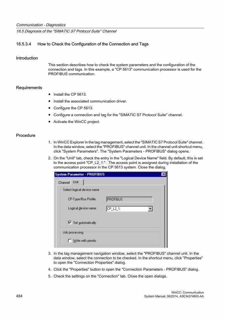
18.5.3.4 How to Check the Configuration of the Connection and Tags
IntroductionThis section describes how to check the system parameters and the configuration of the connection and tags. In this example, a "CP 5613" communication processor is used for the PROFIBUS communication.
Requirements● Install the CP 5613.
● Install the associated communication driver.
● Configure the CP 5613.
● Configure a connection and tag for the "SIMATIC S7 Protocol Suite" channel.
● Activate the WinCC project.
Procedure1. In WinCC Explorer in the tag management, select the "SIMATIC S7 Protocol Suite" channel.
In the data window, select the "PROFIBUS" channel unit. In the channel unit shortcut menu, click "System Parameters". The "System Parameters - PROFIBUS" dialog opens.
2. On the "Unit" tab, check the entry in the "Logical Device Name" field. By default, this is set to the access point "CP_L2_1:" . The access point is assigned during installation of the communication processor in the CP 5613 system. Close the dialog.
3. In the tag management navigation window, select the "PROFIBUS" channel unit. In the data window, select the connection to be checked. In the shortcut menu, click "Properties" to open the "Connection Properties" dialog.
4. Click the "Properties" button to open the "Connection Parameters - PROFIBUS" dialog.
5. Check the settings on the "Connection" tab. Close the open dialogs.
Communication - Diagnostics18.5 Diagnosis of the "SIMATIC S7 Protocol Suite" Channel
WinCC: Communication484 System Manual, 06/2014, A5E34374800-AA

6. In the navigation window, select the checked connection. In the data window, select the tag to be checked. In the shortcut menu, click "Properties" to open the "Tag Properties" dialog. Check the values in the "Type Conversion" and "Data Type" fields.
7. Click the "Select" button to open the "Address properties" dialog. Check the settings for addressing the tag in the AS.
8. Click "OK" to close all open dialogs.
See alsoHow to Check the Channel and the Connection (Page 485)
18.5.3.5 How to Check the Channel and the Connection
IntroductionThis section describes how to check the "SIMATIC S7 Protocol Suite" channel and its connection in Runtime.
Requirements● Install a communication processor in a WinCC computer, for example the CP 5613 for
PROFIBUS communication.
● Install the associated communication driver.
● Configure the CP 5613.
● Create a STEP7 project.
● Configure a connection and tag for the "SIMATIC S7 Protocol Suite" channel.
● Activate the WinCC project.
Overview of Status Messages
Icon DescriptionChannel / connection unconditionally readyChannel / connection ready with some restrictionsChannel / no statement possible regarding connection statusChannel / connection failed
Communication - Diagnostics18.5 Diagnosis of the "SIMATIC S7 Protocol Suite" Channel
WinCC: CommunicationSystem Manual, 06/2014, A5E34374800-AA 485

Procedure1. Start the WinCC Channel Diagnosis from the Start menu.
2. The Channel Diagnosis application window opens. The status information for all installed channels and their connections is displayed on the left on the "Channels/Connections" tab.
3. Check the icon in front of the channel named "SIMATIC S7 Protocol Suite" and the connection. If the channel and connection are OK, a green check mark is displayed in front of each respective entry. For information on the significance of the individual icons refer to the "Overview of Status Messages" table.
4. If there is no green check mark in front of the channel's name and the connection, select the connection in the window on the left. In the window on the right, check the entries for the counters "First Error Code" and "Last Error Code". These values indicate the errors detected. You can access Direct Help by clicking the shortcut menu of the value display.
5. On the "Configuration" tab, select the status and error messages, which are to be output to the log file. This is done by selecting "SIMATIC S7 Protocol Suite" and configuring the error display. For more information, please refer to "Configuring the Log File of a Channel".
6. Check the channel-specific log file. To do this, use a text editor to open the file in the directory "Siemens\WinCC\Diagnose". Check the latest entries with the "ERROR" flag. For more information on this topic, please see "Description of Log File Entries".
7. If you are still unable to pinpoint the error after checking the log file, please activate the Trace function and contact Customer Support.For more information on this topic, refer to "Configuring a Trace Function of a Channel".
Communication - Diagnostics18.5 Diagnosis of the "SIMATIC S7 Protocol Suite" Channel
WinCC: Communication486 System Manual, 06/2014, A5E34374800-AA

See alsoHow to Configure the Trace Function of a Channel (Page 471)
Description of Log File Entries (Page 478)
How to Check a Tag (Page 487)
18.5.3.6 How to Check a Tag
IntroductionIf an external tag does not have the expected value in Runtime, you can use the following procedure to check the tag.
In a "SIMATIC S7 Protocol Suite" channel, you can also use connection-specific internal tags. This procedure can also be used to check these tags.
Requirements● Install a communication module on a WinCC computer, for example the CP 5613 for MPI
communication.
● Install the associated communication driver.
● Configure the CP 5613.
● Create a STEP7 project.
● Configure a connection and tag for the "SIMATIC S7 Protocol Suite" channel.
● Activate the WinCC project.
Procedure1. In WinCC Explorer in the tag management, select the "SIMATIC S7 Protocol Suite" channel.
2. In the data window, select the external tag that you wish to check. To do this, open the directory structure until the tag is displayed in the table area.
3. Move the mouse pointer over the tag to be checked. A tooltip window opens showing the current tag value, the quality code and the last time that the value changed.
4. Check the quality code. If value "80" is displayed, the tag value is OK. A description of the other values can be found under "Tag quality codes".
5. If the quality code is not equal to "80", select the tag in the tag management and click "Properties" in the shortcut menu to open the "Tag Properties" dialog.
6. Check whether values have been configured for the high or low limits, the start or substitute values on the "Limits/Reporting" tab. These values can affect the display.
7. If the tag value is affected by one of the configured values, deactivate the project and change the limit or substitute value.
Communication - Diagnostics18.5 Diagnosis of the "SIMATIC S7 Protocol Suite" Channel
WinCC: CommunicationSystem Manual, 06/2014, A5E34374800-AA 487

Note
In Runtime, the current values of the connection-specific internal tags can be viewed in detail with "WinCC Channel Diagnostics". When the main connection is selected, the tags is shown in the "Counter" column.
Tag values, quality codes etc. are only displayed in Runtime.
See alsoQuality Codes of Tags (Page 508)
Communication - Diagnostics18.5 Diagnosis of the "SIMATIC S7 Protocol Suite" Channel
WinCC: Communication488 System Manual, 06/2014, A5E34374800-AA

18.6 Diagnosis of the "SIMATIC S5 Profibus FDL" Channel
18.6.1 Diagnostic Options for the "SIMATIC S5 PROFIBUS FDL" ChannelThe following options for the detection of errors and the diagnosis of the "SIMATIC S5 PROFIBUS FDL" channel or one of its tags:
Checking the Communication Processor ConfigurationBesides checking the access point, the communication processor can be tested with the "Set PG/PC Interface" application. The communication processor can be checked under SIMATIC NET in the same way.
Checking the Configuration of the Connection and TagsThere may be errors in the configuration of the system and connection parameters. Invalid tag values may also result from improperly addressing the tag in the AS.
Diagnosis of the Channel with "Channel Diagnosis""Channel Diagnosis" can query the status of the channel and connection in Runtime. Any errors that occur are displayed using "Error Codes".
Diagnosis of the Channel TagsIn tag management in Runtime, you can query the current value, the current quality code and the last time that the tag was changed.
See alsoHow to Check a Tag (Page 497)
How to Check the Channel and the Connection (Page 495)
How to Check the Configuration of the Connection and Tags (Page 493)
Checking the Communication Processor under SIMATIC NET (Page 492)
How to Check the Configuration of the Communication Processor (Page 491)
18.6.2 Description of Log File Entries
IntroductionThe channel records errors and important status changes in the log file. These entries can be used to analyze a communications problem.
Each entry in the file has a date and time stamp followed by a flag name and description.
Communication - Diagnostics18.6 Diagnosis of the "SIMATIC S5 Profibus FDL" Channel
WinCC: CommunicationSystem Manual, 06/2014, A5E34374800-AA 489

Example of a logbook entry:2000-05-03 14:43:48,733 INFO Log starting ...
2000-05-03 14:43:48,733 INFO | LogFileName : d:\Siemens\WinCC\Diagnose\SIMATIC_S5_PROFIBUS_FDL_01.LOG
2000-05-03 14:43:48,733 INFO | LogFileCount : 3
2000-05-03 14:43:48,733 INFO | LogFileSize : 1400000
2000-05-03 14:43:48,733 INFO | TraceFlags : fa017fff
Description of the "INFO" Flag Entries
Message text DescriptionLog starting ... Start messageLogFileName : C:\ Siemens\ WinCC\ Diagnose\ "channel_name".LOG
Name of the log file with path
LogFileCount : "n" Number of log files of the channelLogFileSize : "x" Size of the individual log files in bytesTraceFlags : fa017fff Displays the flags used by the Trace function as a
hexadecimal number
18.6.3 Determining the Cause of Incorrect Tag Values
18.6.3.1 How to Determine the Cause of Incorrect TagsIf an unexpected tag value occurs in Runtime, proceed as follows to determine the cause:
1. Check the configuration of the communication processor
2. Check the communication processor under SIMATIC NET
3. Check the configuration of the connection and tags
4. Check the channel and connections
5. Check the tags of the channel
See alsoHow to Check the Configuration of the Connection and Tags (Page 493)
How to Check a Tag (Page 497)
How to Check the Channel and the Connection (Page 495)
Checking the Communication Processor under SIMATIC NET (Page 492)
How to Check the Configuration of the Communication Processor (Page 491)
Communication - Diagnostics18.6 Diagnosis of the "SIMATIC S5 Profibus FDL" Channel
WinCC: Communication490 System Manual, 06/2014, A5E34374800-AA

18.6.3.2 How to Check the Configuration of the Communication Processor
IntroductionThis section describes how to use the "PG/PC Port" program to check a communication processor. In this example, a "CP 5613" type processor is used for the PROFIBUS communication.
Requirements● Install the CP 5613.
● Install the associated communication driver.
● Configure the CP 5613.
Procedure1. On the Control Panel, click the "Set PG/PC Port" icon. The "Set PG/PC Port" dialog is
opened.
2. Check the entry for the access point. The access point "CP_L2_1:/SCP" is automatically added for the PROFIBUS connection when a CP 5613 is installed. Select the entry for this access point. Click "Properties" to open the "Properties - CP5613_5614(PROFIBUS)" dialog.
Communication - Diagnostics18.6 Diagnosis of the "SIMATIC S5 Profibus FDL" Channel
WinCC: CommunicationSystem Manual, 06/2014, A5E34374800-AA 491

3. Check the entry on the "PROFIBUS" tab.
4. Click the "Operational State" tab. Click the "Test" button to execute a function test on the CP 5613. The test results is shown in the output field below. Depending on the test results, you can click the "Restart" button to perform a reset and a complete restart of the CP 5613.
5. Click "OK" to close all open dialogs.
See alsoHow to Check the Configuration of the Connection and Tags (Page 493)
Checking the Communication Processor under SIMATIC NET (Page 492)
18.6.3.3 Checking the Communication Processor under SIMATIC NET
IntroductionThis section explains how to check a communication processor using the "Set PC Station" program in the SIMATIC NET software.
In this example, the "CP 5613" type is used for the PROFIBUS communication to channel "SIMATIC S5 PROFIBUS FDL".
Requirements● Install the CP 5613.
● Install the SIMATIC NET software. For Windows 2000, a version from V6.0 SP5 is required, with Windows XP a version from V6.1 must be installed.
● Configure the CP 5613 under SIMATIC NET.
Procedure1. Activate the Windows Start menu, open "SIMATIC / SIMATIC NET / Settings" and select
menu item "Set PC Station". The "Configurations Console PC Station" dialog opens.
2. Check the entry for the access point. Select the "Access Point" directory in the navigation window. The existing access points are listed in the data window. Upon installation of the CP 5613, access point "CP_L2_1:" for PROFIBUS communication is added automatically. Select this access point in the data window. Use the "Properties" menu item from the shortcut menu to open the "Properties of CP_L2_1:" dialog.
3. Check the entry in the "Assigned Interface Parameters" field. In the case of a CP5613 in a PROFIBUS network, select entry "CP5613_5614(PROFIBUS)".
4. Open the navigation window, select the "Components" directory and then the "CP5613/CP5614" subdirectory.
5. Select the "Network Diagnosis" directory. Click the "Test" button to execute a function test on the CP 5613. The result is displayed in the output window. Depending on the test results, click the "Restart" button in the "General" directory to perform a reset and then a complete restart of the CP 5613.
Communication - Diagnostics18.6 Diagnosis of the "SIMATIC S5 Profibus FDL" Channel
WinCC: Communication492 System Manual, 06/2014, A5E34374800-AA

6. Check the list of participants connected to PROFIBUS in the list in the "Bus Participants" directory. Based on the display, it is possible to determine the function and status of your own station as well as other participants which are connected.
7. Close the dialog.
8. If a fault is detected in the configuration of the communication processor, modifications can only be made to the configuration using SIMATIC NET tools. Further information is available under SIMATIC NET.
See alsoHow to Check the Configuration of the Connection and Tags (Page 493)
18.6.3.4 How to Check the Configuration of the Connection and Tags
IntroductionThis section describes how to check the system parameters and the configuration of the connection and tags.
Requirements● Install the CP 5613.
● Install the communication driver.
● Configure the CP 5613.
● Configure a connection and tag for the "SIMATIC S5 PROFIBUS FDL" channel.
● Activate the WinCC project.
Communication - Diagnostics18.6 Diagnosis of the "SIMATIC S5 Profibus FDL" Channel
WinCC: CommunicationSystem Manual, 06/2014, A5E34374800-AA 493

Procedure1. Click the plus sign in front of the "SIMATIC S5 PROFIBUS FDL" icon in WinCC Explorer
navigation window. In the context menu of the "FDL(CP5412/A2-1)" icon, click "System Parameters". The "System Parameters" dialog opens.
2. Check the entry in the "Device Name" field. By default, this is set to access point "CP_L2_1:/SCP". The access point is assigned during installation of the communication processor in the CP 5613 system. Close the dialog.
3. Click the plus sign in front of the FDL(CP5412/A2-1)" icon. In the context menu of the tag to be tested, select the "Properties" entry. The "Connection Properties" dialog is opened.
4. In the "Connection Properties" dialog, click the "Properties" button. The "Connection Parameters" dialog opens.
Communication - Diagnostics18.6 Diagnosis of the "SIMATIC S5 Profibus FDL" Channel
WinCC: Communication494 System Manual, 06/2014, A5E34374800-AA

5. Check the settings on the "Connection" tab. Close the open dialogs.
6. Click the plus sign in front of the icon of the connection. In the context menu of the tag to be tested, click the "Properties" entry. The "Tag Properties" dialog opens. Check the entries in the "Type Conversion" and "Data Type" fields.
7. In the "Tag Properties" dialog, click the "Select" button. The "Address Properties" dialog opens. Check the settings.
8. Click "OK" to close all open dialogs.
See alsoHow to Check the Channel and the Connection (Page 495)
18.6.3.5 How to Check the Channel and the Connection
IntroductionThis section describes how to check the "SIMATIC S5 PROFIBUS FDL" channel and its connection in Runtime.
Requirements● Install the CP 5613.
● Install the communication driver.
● Configure the CP 5613.
● Create a STEP5 project.
● Configure a connection and tag for the "SIMATIC S5 PROFIBUS FDL" channel.
● Activate the WinCC project.
Overview of Status Messages
Icon DescriptionChannel / connection unconditionally readyChannel / connection ready with some restrictionsChannel / no statement possible regarding connection statusChannel / connection failed
Communication - Diagnostics18.6 Diagnosis of the "SIMATIC S5 Profibus FDL" Channel
WinCC: CommunicationSystem Manual, 06/2014, A5E34374800-AA 495

Procedure1. Start the WinCC Channel Diagnosis from the Start menu.
2. The Channel Diagnosis application window opens. The status information for all installed channels and their connections is displayed on the left on the "Channels/Connections" tab.
3. Check the icon in front of the channel name "SIMATIC S5 PROFIBUS FDL" and the connection. If the status of the channel and connection are OK, a green check mark is displayed in front of each respective entry. For information on the significance of the individual icons refer to the "Overview of Status Messages" table.
4. If there is no green check mark in front of the channel's name and the connection, select the connection in the window on the left. In the window on the right, check the entries for the counters "State", "Error Count", "Error Reason", "Send" and "Receive". These values indicate the errors detected.
5. Check the channel-specific log file. To do this, use a text editor to open the file in the directory "Siemens\WinCC\Diagnose". Check the latest entries with the "ERROR" flag. For more information on this topic, please see "Description of Log File Entries".
6. If you are still unable to pinpoint the error after checking the log file, please activate the Trace function and contact Customer Support.For more information on this topic, refer to "Configuring a Trace Function of a Channel".
See alsoHow to Configure the Trace Function of a Channel (Page 471)
Description of Log File Entries (Page 489)
How to Check a Tag (Page 497)
Communication - Diagnostics18.6 Diagnosis of the "SIMATIC S5 Profibus FDL" Channel
WinCC: Communication496 System Manual, 06/2014, A5E34374800-AA

18.6.3.6 How to Check a Tag
IntroductionIf an external tag does not have the expected value in Runtime, you can use the following procedure to check the tag.
Requirements● Install the CP 5613.
● Install the communication driver.
● Configure the CP 5613.
● Create a STEP5 project.
● Configure a connection and tag for the "SIMATIC S5 PROFIBUS FDL" channel.
● Activate the WinCC project.
Procedure1. In WinCC Explorer in tag management, select the "SIMATIC S5 PROFIBUS FDL" channel.
2. In the data window, select the external tag that you wish to check. To do this, open the directory structure until the tag is displayed in the table area.
3. Move the mouse pointer over the tag to be checked. A tooltip window opens showing the current tag value, the quality code and the last time that the value changed.
4. Check the quality code. If value "80" is displayed, the tag value is OK. A description of the other values can be found under "Tag quality codes".
5. If the quality code is not equal to "80", select the tag in the tag management and click "Properties" in the shortcut menu to open the "Tag Properties" dialog.
6. Check whether values have been configured for the high or low limits, the start or substitute values on the "Limits/Reporting" tab. These values can affect the display.
7. If the tag value is affected by one of the configured values, deactivate the project and change the limit or substitute value.
Note
Tag values, quality codes etc. are only displayed in Runtime.
See alsoQuality Codes of Tags (Page 508)
Communication - Diagnostics18.6 Diagnosis of the "SIMATIC S5 Profibus FDL" Channel
WinCC: CommunicationSystem Manual, 06/2014, A5E34374800-AA 497

18.7 Diagnosis of the "OPC" Channel
18.7.1 Possibilities for Diagnosing the "OPC" ChannelThere are the following possibilities for detecting errors and diagnosing the "OPC" channel or one of its tags:
Checking the Configuration of the Connection and TagsThere may be errors in the configuration of the system and connection parameters. Invalid tag values may also result from improperly addressing the tag in the AS.
Diagnosis of the Channel with "Channel Diagnosis""Channel Diagnosis" can query the status of the channel and connection in Runtime. Any errors that occur are displayed using "Error Codes".
Diagnosis of the Channel TagsIn tag management in Runtime, you can query the current value, the current quality code and the last time that the tag was changed.
See alsoHow to Check a Tag (Page 505)
How to Check the Channel and the Connection (Page 503)
How to Check the Configuration Data (Page 502)
18.7.2 Description of Log File Entries
18.7.2.1 Description of Log File Entries
IntroductionThe channel records errors and important status changes in the log file. The following sections cover only the most important entries. These entries can be used to analyze a communications problem.
A distinction must be made between two types of entries:
● INFO
● ERROR
Communication - Diagnostics18.7 Diagnosis of the "OPC" Channel
WinCC: Communication498 System Manual, 06/2014, A5E34374800-AA

Structure of an Entry
Examples of entries in a logbook2000-03-24 10:43:18,756 INFO Log starting ...
2000-03-24 10:43:18,756 INFO | LogFileName : C:\Siemens\WinCC\Diagnose\OPC.LOG
2000-03-24 10:43:18,756 INFO | LogFileCount : 3
2000-03-24 10:43:18,756 INFO | LogFileSize : 1400000
2000-03-24 10:43:18,756 INFO | TraceFlags : fa000007
000-03-24 10:43:18,756 INFO Process attached at 2000-03-24 09:43:18,746 UTC
2000-03-23 10:46:18,756 INFO Process detached at 2000-03-2410:46:18,746UTC
2000-03-27 13:22:43,390 ERROR ..FOPCData::InitOPC CoCreateInstanceEx- ERROR 800706ba
2000-03-27 13:22:43,390 ERROR - ChannelUnit::SysMessage("[OPC Groups (OPCHN Unit #1)]![OPC_No_Machine]: CoCreateInstance for server "OPCServer.WinCC" on machine OPC_No_Machine failed, Error=800706ba (HRESULT = 800706ba - RPC_S_SERVER_UNAVAILABLE (Der RPC-Server ist nicht verfügbar.))")
See alsoEntries for "ERROR" Flag (Page 500)
Entries for "INFO" Flag (Page 499)
18.7.2.2 Entries for "INFO" Flag
IntroductionEach entry in the file has a date and time stamp followed by a flag name and description.
Examples of entries in a logbook2000-03-24 10:43:18,756 INFO Log starting ...
2000-03-24 10:43:18,756 INFO | LogFileName : C:\Siemens\WinCC\Diagnose\OPC.LOG
2000-03-24 10:43:18,756 INFO | LogFileCount : 3
2000-03-24 10:43:18,756 INFO | LogFileSize : 1400000
Communication - Diagnostics18.7 Diagnosis of the "OPC" Channel
WinCC: CommunicationSystem Manual, 06/2014, A5E34374800-AA 499

2000-03-24 10:43:18,756 INFO | TraceFlags : fa000007
000-03-24 10:43:18,756 INFO Process attached at 2000-03-24 09:43:18,746 UTC
2000-03-23 10:46:18,756 INFO Process detached at 2000-03-2410:46:18,746UTC
Description of the Mst Iportant Logbook Entries
Message text DescriptionLog starting ... Start messageLogFileName : C:\ Siemens\ WinCC\ Diagnose\ "channel_name".LOG
Name of the log file with path
LogFileCount : "n" Number of log files of the channelLogFileSize : "x" Size of the individual log files in bytesTraceFlags : fa000007 Displays the flags used by the Trace function as a
hexadecimal numberProcess attached at 2000-03-24 09:43:18,746 UTC
The channel was loaded by the WinCC Data Manager.
Process detached at 2000-03-2410:46:18,746 UTC
The channel was unloaded by the WinCC Data Manager.
IOPCChnShutdown::ShutdownRequest was called... Reason: system going down" IOPCChnShutdown::ShutdownRequest
The WinCC OPC Server WinCC project was deactivated. The WinCC OPC clients are requested to disconnect from the WinCC OPC server.
18.7.2.3 Entries for "ERROR" Flag
IntroductionEach entry in the file has a date and time stamp followed by a flag name and description. In the case of the "Error" flag, the description consists of a message text, error code and the text of the error message. Some error codes do not have text for an error message.
Examples of entries in a logbook2000-03-27 13:22:43,390 ERROR ..FOPCData::InitOPC CoCreateInstanceEx- ERROR 800706ba
2000-03-27 13:22:43,390 ERROR - ChannelUnit::SysMessage("[OPC Groups (OPCHN Unit #1)]![OPC_No_Machine]: CoCreateInstance for server "OPCServer.WinCC" on machine OPC_No_Machine failed, Error=800706ba (HRESULT = 800706ba - RPC_S_SERVER_UNAVAILABLE (RPC server not available.))")
Communication - Diagnostics18.7 Diagnosis of the "OPC" Channel
WinCC: Communication500 System Manual, 06/2014, A5E34374800-AA

Description of the Most Important Logbook Entries
Error Code Error Message Text Possible Causesc0040004 Conversion between the
"canonicalDatatype" and the "requestedDatatype" is not supported by the server.
Access to the WinCC tag on the OPC server failed.Conversion is possible but failed.The WinCC tag is not on the server or the configured data type does not match.
c0040007 The name does not exist in the name space of the server.
The error code is always returned by the server if the OPC client is accessed with a tag name that does not exist in the name space of the server. Examples: Browse, read tag, write tag, insert tag in a subscription.
00000001 AddItems Access to the WinCC tag on the OPC server failed. The WinCC tag is not on the server or the configured data type does not match.Data Type WinCC Tag OPC Server = Data Type WinCC Tag OPC Client.
80004005 Could not resolve Server Name The computer that is used as the WinCC OPC Server is not available in the network.The WinCC OPC server, which was accessed by the "OPC" channel, was not available.
80040154 Class not registered The WinCC OPC Server is not properly registered in the system.The WinCC OPC Server's WinCC project is not activated.
80070057 Parameter wrong The WinCC tag is not on the OPC Server, or the configured data type does not match.
800706ba The RPC Server is not available.
The computer on which the OPC Server is to be started could not be found in the network.
18.7.3 Determining the Cause of Incorrect Tag Values
18.7.3.1 How to Determine the Cause of Invalid TagsIf an unexpected tag value occurs in Runtime, proceed as follows to determine the cause:
1. Check the configuration data
2. Check connection
3. Check the tags of the channel
See alsoHow to Check a Tag (Page 505)
How to Check the Channel and the Connection (Page 503)
How to Check the Configuration Data (Page 502)
Communication - Diagnostics18.7 Diagnosis of the "OPC" Channel
WinCC: CommunicationSystem Manual, 06/2014, A5E34374800-AA 501

18.7.3.2 How to Check the Configuration Data
Requirements● A computer as WinCC OPC Client with a WinCC Project.
● The "OPC" channel must be integrated in the OPC client's WinCC project.
● Configure a WinCC tag in the OPC server's WinCC project.
● On the OPC client configure a connection and a WinCC tag, which communicates with the created server tags.
● Activate the WinCC project on the OPC Server and Client.
Procedure1. Click the plus sign in front of the "OPC" icon in WinCC Explorer navigation window on the
OPC client. Click the "plus sign in front of the icon "OPC Groups (OPCHN Unit#1)".
2. In the shortcut menu of the tag to be tested, select the "Properties" entry. The "Connection Properties" dialog is opened. Click the "OPC Group" tab.
3. In the field "OPC Server Name", check the ProgID of the OPC server.In the case of a connection to a server with WinCC V 5.0 or higher, you must enter "OPCServer.WinCC".In the case of a server running WinCC V4.x, you must enter "OE.Groups".
4. Enter the name of the computer to serve as the OPC Server in the "Start the server on this computer" field. Click the "Test Server" button to test the connection to the OPC Server. Close the dialog.
5. Click the plus sign in front of the icon of the connection. In the context menu of the tag to be tested, click the "Properties" entry. The "Tag Properties" dialog opens.
6. The same "Data Type" must be entered for this tag as for the tag on the OPC Server.
7. In the "Tag Properties" dialog, click the "Select" button. The "Address Properties" dialog opens.
8. Check the entries in the fields "Item Name" and "Data Type". The "Item Name" must match the tag name on the OPC Server. The "Data Type" must match the data type of the tag on the OPC Server.
9. Check the channel-specific log file. To do this, use a text editor to open the file in the directory "Siemens\WinCC\Diagnose". Check the latest entries with the "ERROR" flag. For more information on this topic, refer to "Description of Log File Entries".
10.If you are still unable to pinpoint the error after checking the log file, please activate the Trace function and contact Customer Support.For more information on this topic, refer to "Configuring a Trace Function of a Channel".
Communication - Diagnostics18.7 Diagnosis of the "OPC" Channel
WinCC: Communication502 System Manual, 06/2014, A5E34374800-AA

See alsoHow to Configure the Trace Function of a Channel (Page 471)
Description of Log File Entries (Page 498)
How to Check the Channel and the Connection (Page 503)
18.7.3.3 How to Check the Channel and the Connection
IntroductionThis section describes how to check the "OPC" channel and its connection in Runtime.
Requirements● A computer as WinCC OPC Client with a WinCC Project.
● The "OPC" channel must be integrated in the OPC client's WinCC project.
● Configure a WinCC tag in the OPC server's WinCC project.
● On the OPC client configure a connection and a WinCC tag, which communicates with the created server tags.
● Activate the WinCC project on the OPC Server and Client.
Overview of Status Messages
Icon DescriptionChannel / connection unconditionally readyChannel / connection ready with some restrictionsChannel / no statement possible regarding connection statusChannel / connection failed
Communication - Diagnostics18.7 Diagnosis of the "OPC" Channel
WinCC: CommunicationSystem Manual, 06/2014, A5E34374800-AA 503

Procedure1. Start the WinCC Channel Diagnosis from the Start menu.
2. The Channel Diagnosis application window opens. The status information for all installed channels and their connections is displayed on the left on the "Channels/Connections" tab.
3. Check the icons in front of the OPC connection. If the status of the connection is OK, a green check mark is displayed in front of the respective entry. For information on the significance of the individual icons refer to the "Overview of Status Messages" table.
4. If there is no green check mark in front of the name of the connection, select the connection in the window on the left. In the window on the right, check the entries for the counters "AddItemFailures", "Server Status", "Last Error" and "Last Error Name". These values indicate the errors detected.
5. Check the channel-specific log file. To do this, use a text editor to open the file in the directory "Siemens\WinCC\Diagnose". Check the latest entries with the "ERROR" flag. For more information on this topic, refer to "Description of Log File Entries".
6. If you are still unable to pinpoint the error after checking the log file, please activate the Trace function and contact Customer Support.For more information on this topic, refer to "Configuring a Trace Function of a Channel".
See alsoHow to Configure the Trace Function of a Channel (Page 471)
Description of Log File Entries (Page 498)
How to Check a Tag (Page 505)
Communication - Diagnostics18.7 Diagnosis of the "OPC" Channel
WinCC: Communication504 System Manual, 06/2014, A5E34374800-AA

18.7.3.4 How to Check a Tag
IntroductionIf an external tag does not have the expected value in Runtime, you can use the following procedure to check the tag.
Requirements● A computer as WinCC OPC Client with a WinCC Project.
● The "OPC" channel must be integrated in the OPC client's WinCC project.
● Configure a WinCC tag in the OPC server's WinCC project.
● On the OPC client configure a connection and a WinCC tag, which communicates with the created server tags.
● Activate the WinCC project on the OPC Server and Client.
Procedure1. In WinCC Explorer in tag management, select the "OPC" channel.
2. In the data window, select the external tag that you wish to check. To do this, open the directory structure until the tag is displayed in the table area.
3. Move the mouse pointer over the tag to be checked. A tooltip window opens with the current tag value, the quality value and the time of the most recent change.
4. Check the quality value. If the value "C0" is displayed, the tag value is OK. A description of the other values can be found under "Tag quality codes".
5. If the quality code is not equal to "C0", select the tag in tag management and click "Properties" in the shortcut menu to open the "Tag Properties" dialog.
6. Check whether values have been configured for the high or low limits, the start or substitute values on the "Limits/Reporting" tab. These values can affect the display.
7. If the tag value is affected by one of the configured values, deactivate the project and change the limit or substitute value.
Note
Tag values, quality codes etc. are only displayed in Runtime.
See alsoQuality Codes of Tags (Page 508)
Communication - Diagnostics18.7 Diagnosis of the "OPC" Channel
WinCC: CommunicationSystem Manual, 06/2014, A5E34374800-AA 505

18.8 Quality of Tags
18.8.1 Quality of Tags
IntroductionIn WinCC, there are two quality indicators that allow you to evaluate the quality of tags. These two indicators are tag status and quality code.
The tag status is formed in WinCC and informs of the quality of configuration settings within the OS. The tag status informs additionally of the connection status to the WinCC communication partner. This may be an automated system or the server computer.
The quality code contains the same information as the tag status. In addition to this information, the quality status contains quality statements on partners which assess or process tags. Possible partners are:
● Automation systems
● Automation systems with field devices
● OPC server
● OPC server with subordinate automation systems
Therein the quality code is forwarded within the processing chain. If at one point in the processing chain several quality codes are pending for a tag, the worst code is forwarded.
The quality code informs of the quality of a tag independent of where this code was formed.
Communication - Diagnostics18.8 Quality of Tags
WinCC: Communication506 System Manual, 06/2014, A5E34374800-AA

Cascading of Quality CodeBy using the example of an automation system with field device connected, the cascading of quality codes shall be outlined.
The automation system reads the quality codes generated by the field device. Using an analysis logic, quality codes pending for the same tag concurrently are evaluated by priority. The quality code with the worst status is assigned to the tag. This quality code must be saved in a data block directly behind the associated tag value.
You may initiate the analysis logic using the channel modules of the PCS7 Library. If the PCS7 Library is not available to you, you must configure the analysis logic in the automation system yourself.
Using one of the communication drivers, WinCC reads the tags from the automation device in Runtime, including the associated quality codes. For each tag, the tag status is formed in the data manager. It contains, for example, violations of configured measurement range limits as well as the status of linkage between WinCC and the automation device.
Using the analysis logic in the data manager, the quality code is generated from the tag status of the data manager and the quality code of the automation device. Here too, the code with the worst status is passed on and saved as quality code by WinCC. For tags that do not have a quality code in the automation system, the quality code is always identical with the tag status.
Communication - Diagnostics18.8 Quality of Tags
WinCC: CommunicationSystem Manual, 06/2014, A5E34374800-AA 507

18.8.2 Quality Codes of Tags
Introduction The quality code is needed to check status and quality of a tag. The displayed quality code summarizes the quality of the entire value transmission and value processing for the respective tag. Thus with the quality code you can for example see whether the current value is a start value or a substitute value.
The quality codes are prioritized. If several codes occur at the same time, the code with the worst status is displayed.
Evaluation of Quality CodesQuality codes can be evaluated in a number of different ways:
● Evaluation with VB scripts
● Evaluation with C scripts
● Evaluation through the dynamic dialog
● Evaluation of the "Quality Code Change Tag" result of an I/O field
Note
In order to include the entire value transfer and value processing in the quality code for a process tag, the connected automation system must support the quality code. When configuring the tags in the AS, make sure there is enough memory space for the quality code. In an AS from the S7 family, for example, the quality code needs an additional byte that is appended to the process value. To prevent errors, this byte must be taken into account when configuring a tag, for instance at the end of a data block.
Display of Quality Codes in Tag ManagementYou can view the quality code of a tag in Tag Management.
Requirements:
● The WinCC project is activated.
● The "Quality Code" column in the Tag Management data area is displayed.
Communication - Diagnostics18.8 Quality of Tags
WinCC: Communication508 System Manual, 06/2014, A5E34374800-AA

Display of Quality Codes in Process PicturesFor the display of tag values in graphic objects with process connection, the quality code may affect the display. If the quality code has a value of 0x80 (good) or 0x4C (initial value), the display of the tag value is not grayed out. For all other values, the display is grayed out. In addition, a yellow warning triangle is displayed for the following objects depending on the set WinCC design:
● I/O field
● Bar, 3D bar
● Check box, radio box
● Group display, status display
● Slider object
StructureThe quality code has the following binary structure:
QQSSSSLLQ: Quality
S: Substatus of the quality
Communication - Diagnostics18.8 Quality of Tags
WinCC: CommunicationSystem Manual, 06/2014, A5E34374800-AA 509

L: Limits. This value is optional.
Note
The quality codes shown in the "Quality" table are basic values of the quality stages. Making use of the substatus and limit elements gives rise to intermediate values over and above the quality stage concerned.
QualityThe first two digits specify the quality of the tag.
Q Q S S S S L L 2
726
25
24
23
22
21
20
Bad - The value is not useful 0 0 - - - - - -Uncertain - The quality of the value is less than normal, but the value may still be useful.
0 1 - - - - - -
Good (non-cascade) - The quality of the value is good. Possible alarm conditions may be indicated by the sub-status.
1 0 - - - - - -
Good (cascade) - The value may be used in control. 1 1 - - - - - -
SubstatusThe quality alone is not enough. Individual qualities are divided into substatuses. The quality code is binary coded. In order to analyze quality codes their values must be converted into their hexadecimal representation.
Quality Codes of TagsPossible quality codes are listed in the following table. At the top of the list, you find the poorest quality code, while the best quality code is shown at the bottom of the list. The best quality code is assigned the lowest priority, while the poorest quality code is assigned the highest priority. If several statuses occur for one tag in the process, the poorest code is passed on.
Code (Hex)
Quality Q Q S S S S L L
0x23 Bad Device passivated - Diagnostic alerts inhibited 0 0 1 0 0 0 1 10x3F Bad Function check - Local override 0 0 1 1 1 1 1 10x1C Bad Out of Service - The value is not reliable because the block is
not being evaluated, and may be under construction by a configuration planner. Set if the block mode is O/S.
0 0 0 1 1 1 - -
0x73 Uncertain Simulated value - Start 0 1 1 1 0 0 1 10x74 Uncertain Simulated value - End 0 1 1 1 0 1 - -0x84 Good
(non-cascade)
Active Update event - Set if the value is good and the block has an active Update event.
1 0 0 0 0 1 - -
Communication - Diagnostics18.8 Quality of Tags
WinCC: Communication510 System Manual, 06/2014, A5E34374800-AA

Code (Hex)
Quality Q Q S S S S L L
0x24 Bad Maintenance alarm - More diagnostics available. 0 0 1 0 0 1 - -0x18 Bad No Communication, with no usable value - Set if there has
never been any communication with this value since it was last "Out of Service".
0 0 0 1 1 0 - -
0x14 Bad No Communication, with last usable value - Set if this value had been set by communication, which has now failed.
0 0 0 1 0 1 - -
0x0C Bad Device failure - Set if the source of the value is affected by a device failure.
0 0 0 0 1 1 - -
0x10 Bad Sensor failure 0 0 0 1 0 0 - -0x08 Bad Not Connected - Set if this input is required to be connected
and is not connected.0 0 0 0 1 0 - -
0x04 Bad Configuration error - Set if the value is not useful because there is some inconsistency regarding the parameterization or configuration, depending on what a specific manufacturer can detect.
0 0 0 0 0 1 - -
0x00 Bad Non-specific - There is no specific reason why the value is bad. Used for propagation.
0 0 0 0 0 0 - -
0x28 Bad Process related - Substitute value 0 0 1 0 1 0 - -0x2B Bad Process related - No maintenance 0 0 1 0 1 0 1 10x68 Uncertain Maintenance demanded 0 1 1 0 1 0 - -0x60 Uncertain Simulated value - Set when the process value is written by
the operator while the block is in manual mode.0 1 1 0 0 0 - -
0x64 Uncertain Sensor calibration 0 1 1 0 0 1 - -0x5C Uncertain Configuration error 0 1 0 1 1 1 - -0x58 Uncertain Subnormal 0 1 0 1 1 0 - -0x54 Uncertain Engineering unit range violation - Set if the value lies outside
of the set of values defined for this parameter. The limits define which direction has been exceeded.
0 1 0 1 0 1 - -
0x50 Uncertain Sensor conversion not accurate 0 1 0 1 0 0 - -0x4B Uncertain Substitute (constant) 0 1 0 0 1 0 1 10x78 Uncertain Process related - No maintenance 0 1 1 1 1 0 - -0x4C Uncertain Initial value - Value of volatile parameters during and after
reset of the device or of a parameter.0 1 0 0 1 1 - -
0x48 Uncertain Substitute value - Predefined value is used instead of the calculated one. This is used for fail safe handling.
0 1 0 0 1 0 - -
0x44 Uncertain Last usable value - Whatever was writing this value has stopped doing so. This is used for fail safe handling.
0 1 0 0 0 1 - -
0x40 Uncertain Non-specific - There is no specific reason why the value is uncertain.
0 1 0 0 0 0 - -
0xE0 Good(cascade)
Initiate fail safe (IFS) - The value is from a block that wants its downstream output block (e.g. AO) to go to fail safe.
1 1 1 0 0 0 - -
0xD8 Good(cascade)
Local override (LO) - The value is from a block that has been locked out by a local key switch or is a Complex AO/DO with interlock logic active. The failure of normal control must be propagated to a function running in a host system for alarm and display purposes. This also implies "Not Invited".
1 1 0 1 1 0 - -
Communication - Diagnostics18.8 Quality of Tags
WinCC: CommunicationSystem Manual, 06/2014, A5E34374800-AA 511

Code (Hex)
Quality Q Q S S S S L L
0xD4 Good(cascade)
Do not select (DNS) - The value is from a block which should not be selected, due to conditions in or above the block.
1 1 0 1 0 1 - -
0xCC Good(cascade)
Not invited (NI) - The value is from a block which does not have a target mode that would use this input.
1 1 0 0 1 1 - -
0xC8 Good(cascade)
Initialization request (IR) - The value is an initialization value for a source (back calculation input parameter), because the lower loop is broken or the mode is wrong.
1 1 0 0 1 0 - -
0xC4 Good(cascade)
Initialization acknowledge (IA) - The value is an initialized value from a source (cascade input, remote-cascade in, and remote-output in parameters).
1 1 0 0 0 1 - -
0xC0 Good(cascade)
OK - No error or special condition is associated with this value. 1 1 0 0 0 0 - -
0xA0 Good(non-cascade)
Initiate fail safe 1 0 1 0 0 0 - -
0x98 Good(non-cascade)
Unacknowledged critical alarm - Set if the value is good and the block has an unacknowledged alarm with a priority greater than or equal to 8.
1 0 0 1 1 0 - -
0x94 Good(non-cascade)
Unacknowledged advisory alarm - Set if the value is good and the block has an unacknowledged alarm with a priority less than 8.
1 0 0 1 0 1 - -
0x90 Good(non-cascade)
Unacknowledged update event - Set if the value is good and the block has an unacknowledged update event.
1 0 0 1 0 0 - -
0x8C Good(non-cascade)
Active critical alarm - Set if the value is good and the block has an active alarm with a priority greater than or equal to 8.
1 0 0 0 1 1 - -
0x88 Good(non-cascade)
Active advisory alarm - Set if the value is good and the block has an active alarm with a priority less than 8.
1 0 0 0 1 0 - -
0xA8 Good(non-cascade)
Maintenance demanded 1 0 1 0 1 0 - -
0xA4 Good(non-cascade)
Maintenance required 1 0 1 0 0 1 - -
0xBC Good(non-cascade)
Function check - Local override 1 0 1 1 1 1 - -
0x80 Good(non-cascade)
OK - No error or special condition is associated with this value. 1 0 0 0 0 0 - -
Communication - Diagnostics18.8 Quality of Tags
WinCC: Communication512 System Manual, 06/2014, A5E34374800-AA

LimitQuality codes can be further subdivided by limits. Limits are optional.
Q Q S S S S L LO.K. - The value is free to move. - - - - - - 0 0Low limited - The value has acceded its low limits. - - - - - - 0 1High limited - The value has acceded its high limits. - - - - - - 1 0Constant (high and low limited) - The value cannot move, no matter what the process does.
- - - - - - 1 1
Quality Codes in Communication with OPCIn the communication via the "OPC" channel, the quality codes that the OPC does not support are converted.
Quality Code in WinCC Quality Code in OPC0x48 0x400x4C 0x400x5C 0x400x60 0x400x80...0xD4 0xC00xD8 0xC0
18.8.3 Tag Status
IntroductionThe tag status of individual WinCC tags can be monitored in Runtime. The tag status contains, among other information, data regarding violations of the configured measurement range limits as well as the status of linkage between WinCC and automation device.
The quality code informs of the quality of a tag independent of where this code was formed. Thereby, the status of the entire value transfer and value processing are taken into consideration.
For example, if a violation occurs of the measurement range at the lower limit, quality code "0x55" is communicated. This violation of the measurement range might have occurred in the WinCC data manager or in the field device. The tag status allows you to find out if this measurement range violation occurred in WinCC or prior to passing the value to WinCC.
For example, if the tag status reports a limit violation with code 0x0010, it indicates that the values remained below the lower range limit configured in WinCC. If the tag status does not report any limit violation, the quality code passed on to WinCC already contained the limit violation.
Communication - Diagnostics18.8 Quality of Tags
WinCC: CommunicationSystem Manual, 06/2014, A5E34374800-AA 513

Evaluation of Quality CodesQuality codes can be evaluated in a number of different ways:
● Evaluation with C scripts
● Evaluation through the dynamic dialog
● Evaluation of the "Quality Code Change Tag" result of an I/O field
WinCC Status FlagsPossible tag statuses are contained in the following table.
Name of flag Value Description 0x000
0No error
DM_VARSTATE_NOT_ESTABLISHED
0x0001
Connection to partner not established
DM_VARSTATE_HANDSHAKE_ERROR
0x0002
Handshake error
DM_VARSTATE_HARDWARE_ERROR
0x0004
Network module defective
DM_VARSTATE_MAX_LIMIT 0x0008
Configured upper limit exceeded
DM_VARSTATE_MIN_LIMIT 0x0010
Configured lower limit exceeded
DM_VARSTATE_MAX_RANGE 0x0020
Format upper limit exceeded
DM_VARSTATE_MIN_RANGE 0x0040
Format lower limit exceeded
DM_VARSTATE_CONVERSION_ERROR
0x0080
Display conversion error (in connection with format limit xxx exceeded)
DM_VARSTATE_STARTUP_VALUE 0x0100
Tag initialization value
DM_VARSTATE_DEFAULT_VALUE 0x0200
Tag replacement value
DM_VARSTATE_ADDRESS_ERROR
0x0400
Channel addressing error
DM_VARSTATE_INVALID_KEY 0x0800
Tag not found / not available
DM_VARSTATE_ACCESS_FAULT 0x1000
Access to tag not permitted
DM_VARSTATE_TIMEOUT 0x2000
Timeout / no check-back message from the channel
DM_VARSTATE_SERVERDOWN 0x4000
Server not available.
Communication - Diagnostics18.8 Quality of Tags
WinCC: Communication514 System Manual, 06/2014, A5E34374800-AA

18.8.4 Using the Tag Status to Monitor Connection Status
IntroductionThe status of individual WinCC tags can be monitored in Runtime, providing information about the status of the associated connection.
The monitoring is configured in Graphics Designer as an object property. One possibility for monitoring would be to use the "Text" property of a static text.
In the shortcut menu of the "Dynamic" dialog for the desired property, select "Dynamic Dialog" to open the "Dynamic value ranges" dialog.
The following settings are specified here:
● Tag to be monitored
● For tag value: assignment of validity range and status display
Communication - Diagnostics18.8 Quality of Tags
WinCC: CommunicationSystem Manual, 06/2014, A5E34374800-AA 515

● The activation of the tag status evaluation
● For the status: assignment of validity range and corresponding status text
In Runtime, one of the entered status texts, which corresponds to the tag's current status, is displayed in the configured object.
18.8.5 Monitoring Tag Status Using Global Actions
IntroductionOne way to monitor the status of a tag is to make use the internal functions "GetTagState" and "GetTagStateWait" in the Global Script editor. In contrast to the "GetTag" and "GetTagWait" functions, these not only return the tag's value but also its status. This status value can be evaluated and then used to trigger various events. It can also be used to assess the status of the associated connection.
In the global action, the status value of the monitored tag is determined using the "GetTagState" function for this tag type. There is such a function for each tag type. The status value "0" indicates a good connection with no errors. This status can now be evaluated as desired.
Example:This example illustrates the monitoring of a WinCC tag of the type "Signed 16-Bit Value". The "GetTagSWordState" function is used to determine the status of this tag. The first function parameter is the name of the WinCC tag to be monitored. The second parameter gives where the returned status value is to be written.
Communication - Diagnostics18.8 Quality of Tags
WinCC: Communication516 System Manual, 06/2014, A5E34374800-AA

The tag status is output in the internal tag BINi_E_CONNECTION. In the event of an error, the value of this tag is set to TRUE. In the error handling, the tag can, for example, be used to trigger an alarm or display an error message.
18.8.6 How to Check an Internal Tag
IntroductionIf an internal tag does not have the expected value in Runtime, you can use the following procedure to check the tag.
Requirements● An internal tag has been configured.
● The WinCC project is activated.
Procedure1. Open Tag Management in the WinCC Explorer.
2. Select the entry "Internal tags" and the tag to be checked in the navigation area.
3. To display the "Quality Code" and "Value" columns in the data area, you may have to go to "Show" and select these columns in the shortcut menu of a column header.
4. Check the quality code. If the value "80" is displayed, the tag value is OK. A description of the other values can be found under "Tag Quality Codes".
5. If the quality code is not equal to "80", check the settings under properties on the right.
6. Check whether values have been configured for the upper and lower limits or start value. These values can affect the display.
7. If the tag value is affected by one of the configured values, deactivate the project and change the limit or substitute value.
Communication - Diagnostics18.8 Quality of Tags
WinCC: CommunicationSystem Manual, 06/2014, A5E34374800-AA 517

Note
The tag value and the quality codes are only displayed in Runtime.
See alsoQuality Codes of Tags (Page 508)
Communication - Diagnostics18.8 Quality of Tags
WinCC: Communication518 System Manual, 06/2014, A5E34374800-AA

Index
A&E server
Mapping WinCC message classes and message types, 186
as ActiveX Control, 468 Connecting WinCC - OPC A&E client
Example of OPC A&E , 178 OPC A&E server , 173, 186 Testing, 465
""MPI" channel unit, 312
Configuring the connection, 312"Slot PLC" channel unit, 319
Configuring the connection, 319"System Info" channel, 473
Diagnostic option, 473
5505-Ethernet (CP 1413-x)
Channel Unit, 397
AA&E server, 171, 172, 181, 183, 186
Condition Related Event, 171Conditional event, 181Mapping the WinCC message system, 186Simple event, 181Tracking event, 171, 181
A&E ServerHierarchical access, 183Mapping of the WinCC message system, 172
Acknowledgement theory, 176Acknowledgment policy, 189Adding a tag, 81, 89
Example of OPC DA, 138Adding new drivers, 258Address properties, 93, 108, 261, 262, 263, 267
Example for S5 Profibus FDL, 276Address type
Mitsubishi Ethernet, 64Addresses of tags, 401
TI Ethernet Layer 4, 401AR_SENDAR_SEND-FunctioninWinCC , 337AR_SEND-Function in WinCC
Configuring Variants for an Archive Tag, 364Configuring Variants for Multiple Archive Tags, 367Data Block,Structure and Parameters, 338Example for Data Block Structure, 347, 348, 349, 354, 356, 358, 360, 363Overview of the properties of the variants, 343Variants for an Archive Tag, 345Variants for Multiple Archive Tags, 350Variants for Multiple Archive Tags (optimized), 362
AS data type, 17Type conversion, 27
AS511, 279Automation device, 256
BBar
Example of System Info, 446BinWrite Mechanism, 35
General Procedure, 35Bit by bit access, 35, 237, 325
S5 AS511, 286S5 Ethernet Layer 4, 237S5 Profibus FDL, 261S5 Serial 3964R, 295S7 Protocol Suite, 325TI Ethernet Layer 4, 403TI Serial, 414
Bit/Byte access, 35Bit-/Byte-tag, 37Block, 273
Cyclic block, 273Bounding values, 155Buffer time, 179Byte array, 267Byte by byte access, 35, 238, 325
S5 AS511, 287S5 Ethernet Layer 4, 238S5 Profibus FDL, 262S5 Serial 3964R, 297S7 Protocol Suite, 327TI Ethernet Layer 4, 404TI Serial, 415
WinCC: CommunicationSystem Manual, 06/2014, A5E34374800-AA 519

CChannel, 15, 231, 289, 300, 503
check, 474, 485, 495Configuring SIMATIC S5 PROFIBUS FDL, 258Diagnosis of channels, 465Example for S5 PROFIBUS FDL, 273Mitsubishi Ethernet, (See Mitsubishi Ethernet)PROFIBUS FMS, 221SIMATIC S5 Ethernet Layer 4, 231SIMATIC S5 Programmers Port AS511, 279SIMATIC S5 Serial 3964R, 289SIMATIC S7 Protocol Suite, 300SIMATIC TI Ethernet Layer 4, 397Status - Logical Connections function , 465Testing, 503TI Serial, 409
Channel , 221Channel diagnosis, 467
"System Info" channel, 473Chanel with , 468, 470Channel diagnosis, 467, 468, 469Channel diagnosis as Windows application , 469Channel diagnosis with , 468Channel diagonsis, 465Channel with Status - Logical Connections function , 465Checking configuration data, 502Checking connection, 503Checking internal tags, 517Checking the configuration of the communication processor, 481, 483, 491, 492Configuring a the Trace function of a channel, 471Connection parameters, 493Diagnostic option, 473, 478, 489, 498ERROR flag of logbook entry, 473, 478Example, 516Function , 465INFO flag of logbook entry, 473, 478, 489, 498Log file, 473, 478, 489, 498Monitoring of tag status in dynamic dialog, 515Monitoring of tag status with global actions, 516OPC channel, 498Overview of status messages, 503PROFIBUS system parameters, 484Properties - CP5613, 481, 483, 491, 492SIMATIC S5 PROFIBUS FDL channel, 489SIMATIC S7 Protocol Suite channel, 478Standard flags of the Trace function, 471Status - Logical Connections, 465
System parameters, 493Testing channel, 503WinCC channel diagnosis, 503
Channel DiagnosisChannel diagnosis with , 467Checking connection, 474, 485, 495Overview of status messages, 474, 485, 495Testing channel, 474, 485, 495WinCC channel diagnosis, 474, 485, 495
Channel diagnosis channel Testing, 468, 470
Channel diagnosis Channel DiagnoseChannel diagnosis Channel Diagnose , 469Channel diagnosis with Channel Diagnose , 468
Channel Diagnosis trace file , 467Channel diagnostics
Checking tag, 476, 487, 497, 505Channel unit
Connection parameters, 399S5 Transport (CP1413-x), 233S5 Transport (TCP/IP), 233S5-AS511, 281
Channel Unit, 15, 231, 258, 302505 Serial Unit #1, 409505-Ethernet (CP 1413-x), 397FDL (CP5412/A2-1), 258Industrial Ethernet, 309MPI, 312Named Connections, 314PROFIBUS, 317PROFIBUS-FMS, 223S5-AS511, 279S5-RK512 (3964R), 289Selection for SIMATICS7ProtocolSuiteS7 Protocol Suite channel:Selecting the channel unit, 302Slot PLC, 319Soft PLC, 321System parameters, 242, 264, 331, 405, 406TCP/IP, 322
Channel unit FDL (CP5412/A2-1), 253, 258Channel Unit Industrial Ethernet, 309
Configuring the connection, 310Channel units
Mitsubishi Ethernet, (See Mitsubishi Ethernet)Commissioning, 220Communication, 13
Addressing in the automation system, 17AS data type, 20, 27Basis, 13BinWrite Mechanism, 35Bit-/Byte-access, 35
Index
WinCC: Communication520 System Manual, 06/2014, A5E34374800-AA

Bit-/Byte-tag, 37Channel Unit, 15Communication between WinCC and Automation systems, 15Communication driver, 15Configuring a tag with BinWrite, 37Configuring powertags, 20Connection, 15Connection properties, 19Creating a new connection, 19Data type, 17, 27Length definition for text tags, 17Linear scaling of numerical tag types, 17PowerTag, 17Principle of the BinWrite-Mechanism, 35Principle of WinCC communication, 15Sorting format adaptation by AS data type, 27Sorting format adaptation by WinCC data type, 21Tag Properties, 20Type conversion, 27Type Conversion, 17Value range, 27WinCC data types, 17WinCC process communication, 15WinCC Type Conversion, 17
Communication driver, 15, (See channel)Communication processor, 481, 483, 491, 492
Checking the configuration of the communication processor, 481, 483, 491, 492
Communication type, 268Configuring, 268
Compatibility, 125Configuration data, 502Configuration file
File location, 216Layout, 216Port number, 216Security settings, 216URL of the WinCC OPC UA server, 216User identification, 216WinCC archive write access, 216
Configure bit by bit accessTag, 403
Configure byte by byte accessTag, 404
configuringOptimized WinCC archive write access, 219Port number, 218Security settings, 218User identification, 219WinCC OPC UA Server, 217
ConfiguringTag, 401TI Ethernet Layer 4, 399
Configuring a tagTI Ethernet Layer 4, 401
Configuring a tag with bit by bit accessTI Ethernet Layer 4, 403
Configuring a tag with byte by byte accessTI Ethernet Layer 4, 404
Connecting WinCC - OPC A&E client, 178Connection, 15, 308, 503
Active connection, 253check, 474, 485, 495Configuring, 259, 310, 312, 315, 317, 319, 321, 323Creating a connection, 81Creating a new connection, 19Passive connection, 253Testing, 503Testing configuration of connection, 484, 493
Connection Monitoring, 86Connection parameters, 15, 233, 258, 259, 269, 271, 308, 493
Channel unit, 399PROFIBUS FMS, 221S5 AS511, 279, 281S5 Ethernet Layer 4, 231S7 Protocol Suite, 300SIMATIC S5 Serial 3964R, 289TI Ethernet Layer 4, 397, 399TI Serial, 409
Connection properties, 19, 259, 269, 271Counter, 436CP1434 TF, 406, 407CPU load, 436
Example of System Info, 447Cyclic Read Services, 332
DData area, 255Data transmission, 268
Configuring a passive data transfer, 271Configuring an active data transfer, 269
Data type, 17, 85, 306, 390, 436Data types used, 436, 443Mitsubishi Ethernet, 60, 64S5 AS511, 280S5 Profibus FDL, 255S5 Serial 3964R, 290S7 Protocol Suite, 306SIMATIC S7-1200, S7-1500 Channel, 390
Index
WinCC: CommunicationSystem Manual, 06/2014, A5E34374800-AA 521

Supported WinCC data types, 85Supported WinCC data types overview, 85TI Ethernet Layer 4, 398Type conversion, 27
Data Types, 17, 232PROFIBUS FMS, 221, 222S5 Ethernet Layer 4, 232TI Ethernet Layer 4, 398
Date, 436Daylight Saving/Standard Time, 338Defining new tag, 145
Example of OPC DA, 145Device Name, 242, 264, 405
change, 265TI Ethernet Layer 4, 405
DiagnosisChannels, 429
Diagnostic option, 473, 478, 489, 498"System Info" channel, 473OPC channel, 498SIMATIC S5 PROFIBUS FDL channel, 489SIMATIC S7 Protocol Suite channel, 478
Disk capacity, 436Example of System Info, 446Free dive capacity, 436, 441
EERROR flag, 473, 478E-server
Functionality of WinCC OPC A&OPC, 129Example:, 516
FFilter criteria, 89Functionality of the OPC A&E server
Conditional event, 181Simple event, 181Tracking event, 181
Functionality of the WinCC OPC A&E serverSimple event, 171
II/O field
Example for S5 Profibus FDL, 276Example of System Info, 444
I/O field configuration, 138Example of OPC DA, 138
INFO flag, 473, 478, 489, 498
Item handle, 155Item ID, 155
LLife beat monitoring for channel S5Seral3964R
Life beat monitoring , 291Log file, 473, 478, 489, 498Logbook entry, 473, 478, 489, 498Logbook file, 467Logical Device Name, 331
modify, 335
MMax size, 179MELSEC FX3U series, (See Mitsubishi Ethernet)MELSEC Q series, (See Mitsubishi Ethernet)Message
Example of System Info, 448, 450Message classes on OPC A&E servers, 186Message text, 448Message types on OPC A&E servers, 186Mitsubishi Ethernet, 59
Address types, 64Channel units, 59, 61, 63Configure connections, 61Configuring a tag, 61, 64, 66Configuring connections, 61, 63Controllers that are supported, 61Data types, 60, 64Tag, 66
Multi-user system, 456Use of channel , 456
NNamed Connections channel unit, 314
Configuring the connection, 315Network, 13New connection, 89New user, 128Numerical tag type, 17
Linear Scaling, 17
OOPC
Access to tag, 87Adding a tag, 81, 89
Index
WinCC: Communication522 System Manual, 06/2014, A5E34374800-AA

Address properties, 93, 108Channel diagnosis, 498Communications concept, 126Compatibility, 125Configuring access to a WinCC archive tag using the HDA server browser, 165Configuring access to a WinCC tag with the OPC Item Manager, 89Configuring access to a WinCC tag without the OPC Item Manager, 93, 108Configuring access to the WinCC message system, 179Configuring an OPC channel on a WinCC OPC DA client, 88Configuring structure, 96Configuring structure tag, 96Creating a connection, 81Error handling in event of disturbed OPC communication, 98, 118Example, 141, 142, 143, 145, 148, 149, 150, 152Example:, 137, 138, 163Filter criteria, 89Functionality of the OPC A&E server, 181Functionality of the WinCC OPC A&E server, 171Functionality of the WinCC OPC DA Client, 86Functionality of the WinCC OPC DA server, 134Functionality of the WinCC OPC HDA server, 154Functionality of the WinCC OPC UA client, 111Functionality of the WinCC OPC XML client, 103Functionality of WinCC OPC XML server, 129HDA server browser, 164New connection, 89New user, 128OPC in WinCC, 79, 126OPC Item Manager, 81OPC1, 93, 108OPCServer.WinCC-(DPC_4001), 89Overview of OPC Item Manager functions, 81Principle of operation of the WinCC OPC UA Server , 197ProgID, 136Querying of ProgID, 81Setting up user account on the OPC computers, 128Specifications, 125Structure properties, 96Supported WinCC data types, 85Supported WinCC data types overview, 85Tag selection, 81Trace, 220Using Multiple OPC DA Servers, 135
Using structures on a WinCC OPC DA client, 95, 97WinCC as an OPC DA client, 79, 98WinCC as OPC UA client, 118WinCC as OPC XML client, 79
OPC A&E ClientExample of OPC A&E , 178
OPC A&E server, 171, 178, 181, 183Quality codes, 191
OPC A&E Server, 179Configuring access to the WinCC message system, 179Quality codes, 178
OPC A&E servers, 129OPC A&Raw Data, 178OPC channel, 498
Configuring an OPC channel on a WinCC OPC DA client, 88Diagnostic option, 498
OPC communication, 98, 118Error handling in the event of disturbed OPC DA communication, 98Handling errors in OPC UA communication, 118
OPC DA client, 86Functionality of the WinCC OPC DA Client, 86
OPC DA server, 134Functionality of the WinCC OPC DA server, 134Using multiple OPC DA servers, 135
OPC HDA server, 154Assemblies, 157Attributes, 156Bounding values, 155Data structure, 155, 156Item handle, 155Item ID, 155Principle of operation, 154Quality codes, 160, 178Raw data, 154Supported functions, 158Time Format of a WinCC OPC HDA server, 158Write Accesses, 161
OPC Item Manager, 81, 89, 136Overview of OPC Item Manager functions, 81
OPC UA Display of the WinCC tags, 207Access to tag, 111Conformance units, 205Display of the logging tags, 208Profile, 205
OPC UA client, 111Functionality of the WinCC OPC UA client, 111
OPC UA Data Access, 208
Index
WinCC: CommunicationSystem Manual, 06/2014, A5E34374800-AA 523

OPC UA Historical Access, 209OPC UA Server
Communication profile, 197Configuration file, 215How it works, 197Instance certificate, 199Security concept, 198supported specifications, 197Trusted client certificates, 200URL, 197
OPC XML, 132Access to tag, 104Security settings in IIS, 132Testing installation, 132
OPC XML client, 103Functionality of the WinCC OPC XML client, 103
OPC XML server, 129Installation, 130
OPC1, 93, 108OPCScout new project1
Example of OPC DA, 145OPCServer.WinCC-(DPC_4001), 89
PPoint of error, 448Printer monitoring, 436
Example of System Info, 452Process picture
Example of System Info, 460PROFIBUS Channel Unit, 317
Configuring the connection, 317PROFIBUS FMS, 221
Addresses of tags, 228, 229Configuring a tag, 227, 228, 229Connection parameters, 223Data Types, 222PROFIBUS FMS channel unit, 226PROFIBUS FMS Channel Unit, 223
PROFIBUS FMS communication driverPROFIBUSFMS , 221
PROFIBUS system parameters, 484ProgID, 81
Querying, 136Querying of ProgID, 81
ProjectExample of OPC DA, 138
Properties - CP5613, 481, 483, 491, 492
QQuality codes, 160, 178, 191Quality codes of tags, 506, 508
RRaw data, 154Raw Data Tag, 267, 369
as byte array, 267, 370Configuring, 267Configuring as a byte array, 371Configuring for BSEND/BRCV functions, 376for BSEND/BRCV functions, 373
SS5 AS511, 281
Configuring, 281Configuring a tag, 283Configuring a tag with bit by bit access, 286Data Types, 280Defining a tag with byte by byte access, 287Tag address, 283
S5 Ethernet Layer 4, 231Configuring, 233Configuring a tag, 235Configuring a tag with bit by bit access, 237Configuring a tag with byte by byte access, 238Configuring a tag with word by word access, 239Connection parameters, 233Data Types, 232Device Name, 242, 243Error codes during connection disturbances, 246iNA960 messages, 249Internal error codes and constants, 246Raw Data Tag, 241SCI messages, 250System parameters of the channel unit, 242Tag address, 235Transport Parameter, 242, 244
S5 Profibus FDL, 253Access to a S5 tag of data type ARRAY OF BYTE, 255Access to a S5 tag of data type BIT, 255Access to a S5 tag of data type BYTE, 255Access to S5 tags, 255Active connection, 253Adding new drivers, 258Address properties, 261, 262, 263, 267
Index
WinCC: Communication524 System Manual, 06/2014, A5E34374800-AA

Block, 273Changing the device name, 265Changing write/read monitoring time, 266Channel diagnosis, 489Channel unit FDL (CP5412/A2-1), 253Configuring a passive data transfer, 271Configuring a raw data tag, 267Configuring a tag, 261Configuring a tag with bit by bit access, 261Configuring a tag with byte by byte access, 262Configuring a tag with word by word access, 263Configuring an active data transfer, 269Configuring channel SIMATIC S5 Profibus FDL, 258Configuring data handling blocks, 273Configuring SIMATIC S5 Profibus FDL, 258Configuring the communication type, 268Configuring the connection, 259Connection parameters, 258, 259, 269, 271Connection properties, 259, 269, 271Cyclic block, 273Data area, 255Data type, 255Device Name, 264Example, 273, 276Features of the channel, 256Passive connection, 253Raw data tag as byte array, 267Service Access Point, 253Special function, 267Startup block, 273supported data type, 255System parameters, 265, 266System parameters of the channel unit, 264Tag parameter, 258Tag Properties, 261, 262, 263, 267Type conversion, 256Write/Read monitoring time, 264
S5 Serial 3964R, 289Configuring, 291Configuring a tag, 293Configuring a tag with bit by bit access, 295Configuring a tag with byte by byte access, 297Data type of the tags, 290
S5 tag, 255Access to a S5 tag of data type ARRAY OF BYTE, 255Access to a S5 tag of data type BIT, 255Access to a tag of data type byte, 255Access to S5 tags, 255
S7 Protocol Suite, 300AR_SEND variant for an archive tag, 345
AR_SEND variant for multiple archive tags, 350AR_SEND variant for multiple archive tags (optimized), 362Changing logical device names, 335Channel diagnosis, 478Channel Unit, 302, 308Configuring, 307Configuring a raw data tag as a byte array, 371Configuring a tag with bit by bit access, 325Configuring a tag with byte by byte access, 327Configuring a tag with word by word access, 328Configuring a text tag, 329Configuring an AR_SEND variant for an archive tag, 364Configuring an AR_SEND variant for multiple archive tags, 367Configuring software redundancy, 383Configuring system parameters, 333Configuring the connection, 310, 312, 315, 317, 319, 321, 323Configuring the raw data tag for the BSEND/BRCV functions, 376Cyclic Read Services, 332Data exchange with FB S7ProtocolSuite:AR_SEND variants , 337Data type, 306Delete Software Redundancy in WinCC, 386Error codes during connection disturbances, 387Example for Data Block Structure AR_SEND, 347, 348, 349, 354, 356, 358, 360, 363Overview of the properties of the AR_SEND variants, 343Raw Data Tag, 369Raw data tag as byte array, 370Raw data tag for BSEND/BRCV functions, 373Software Redundancy, 377Software Redundancy - Connection-specific internal tags, 379Structure and Parameter of Data Block in AR_SEND Function, 338supported data type, 306System parameters, 331
Service Access Point, 253SIMATIC S5 Profibus FDL, 253
Raw Data Tag, 267S5 Profibus FDL, 253Special function, 267
SIMATIC S5 PROFIBUS FDL channel, 489Diagnostic option, 478
SIMATIC S5 Programmers Port AS511, 279SIMATIC S5 Serial 3964R, 289SIMATIC S5 Serial 3964R , 291
Index
WinCC: CommunicationSystem Manual, 06/2014, A5E34374800-AA 525

SIMATIC S7 Protocol Suite, 300SIMATIC S7 Protocol Suite channel, 478
Diagnostic option, 478SIMATIC S7-1200, S7-1500 Channel
Configuration, 391Configuring the connection, 391Data type, 390
SIMATIC TI Ethernet Layer 4, 397Channel, 397Transport Parameter, 405
SIMOTION channel, 417Configuring, 419, 420, 421, 423, 424Data types, 418Diagnosis, 429System parameters, 425, 427
Soft PLC channel unit, 321Configuring the connection, 321
Software Redundancy, 377configure in WinCC, 383Connection-specific internal tags, 379delete in WinCC, 386
Special function, 267Standard flag, 471Startup block, 273Status - Logical Connections functionStatus - Logical Connection, 465Status display, 474, 485, 495, 503
Example of System Info, 452Structure
Configuring structure, 96Using structures on a WinCC OPC DA client, 95Using WinCC OPC client, 97
Structure properties, 96Structure tag, 96
Configuring structure tag, 96Supported system information, 436
Overview, 436System Info, 434
Bar configuration, 446Channel diagnosis, 473Configuring, 442Data types used, 443, 457Differences to other software components, 441Example, 443, 457, 458, 460, 461Example:, 444, 446, 447, 448, 450, 452, 459Free dive capacity, 436I/O field configuration, 444Message text, 448Overview of supported system information, 436Overview of the Supported System Information, 436Point of error, 448
Status display configuration, 452Tag to be monitored, 448
System Info System informationUse in multi-user system , 456
System parameters, 15, 242, 331, 425, 427, 493Channel Unit, 405, 406Configuring, 333, 335S5 Ethernet Layer 4, 231S5 Profibus FDL, 253SIMATIC S7 Protocol Suite, 300TI Ethernet Layer 4, 397, 405, 406, 407
TTag, 17, 235, 443, 505, 506
Adding a tag, 81Addressing external tags in the automation system, 17Check, 476, 487, 497, 505Checking internal tags, 517Configure bit by bit access, 237, 261, 295, 325, 403, 414Configure byte by byte access, 238, 262, 297, 327, 404, 415Configuring, 227, 228, 229, 235, 261, 401, 413Configuring a tag with BinWrite, 37Configuring a text tag, 20Configuring external tags, 20Configuring HDA server browser, 165Configuring linear scaling, 20Configuring OPC Item Manager, 89, 93Configuring PC Item Manager, 108Configuring powertags, 20Configuring tag addresses, 293Configuring word by word access, 239, 263, 328Example of OPC DA, 145, 148, 152Example of OPC HDA, 165, 166Example of System Info, 443, 459External, 17HDA server browser, 164Length definition for text tags, 17OPC Item Manager, 89PowerTag, 17Quality, 506Quality code, 506Quality codes, 508Status, 506, 513Tag selection, 81Testing configuration of tags, 484, 493
Tag address, 235PROFIBUS FMS, 221, 222, 228, 229S5 Ethernet Layer 4, 231
Index
WinCC: Communication526 System Manual, 06/2014, A5E34374800-AA

TI Serial, 409Tag Properties, 20, 261, 262, 263, 267
Example for S5 Profibus FDL, 276Tag status, 506, 513, 515, 516
Monitoring of tag status in dynamic dialog, 515Monitoring of tag status with global actions, 516
Tag to be monitored, 448TCP/IP channel unit, 322
Configuring the connection, 323Text Tag, 17, 325
Configuring, 20, 329TI Ethernet Layer 4, 397
Addresses of tags, 401Bit by bit access, 403Byte by byte access, 404Configuring, 399Configuring a tag, 401Configuring a tag with bit by bit access, 403Configuring a tag with byte by byte access, 404Connection parameters, 397, 399Data type, 398Data Types, 398Device Name, 405System parameters, 397, 405, 406, 407Transport Parameter, 405
TI Serial, 409Addresses of tags, 413Configuring, 411Configuring a tag, 413Configuring a tag with bit by bit access, 414Configuring a tag with byte by byte access, 415Connection parameters, 411Data Types, 410Tag address, 413
Time, 436, 441Example of System Info, 444
Time stamp, 338Timer, 436Trace function, 471
Configuring, 471Transferring Changes, 332Transport Parameter, 15, 242
SIMATIC S5 Ethernet Layer 4, 242SIMATIC TI Ethernet Layer 4, 405TI Ethernet Layer 4, 405
TTY interface, 279Type conversion, 27, 256Type Conversion, 17
UURL
OPC UA Server, 197User account, 128
Making OPC computers known, 128
VValue range, 27Variable, 325
WWinAC Basis, 321WinAC Pro, 319WinCC
as OPC DA client, 79, 98as OPC UA client, 118as OPC XML client, 79OPC in WinCC, 79, 98, 118, 126
WinCC - Microsoft Excel Connection, 149Example of OPC DA, 149
WinCC - OPC HDA client connection, 163Example of OPC HDA, 163
WinCC - SIMATIC NET FMS OPC server connection, 141
Example of OPC DA, 141WinCC - SIMATIC NET S7 OPC server connection, 143
Example of OPC DA, 143WinCC - WinCC connection, 137
Example of OPC DA, 137WinCC channel diagnosis, 474, 485, 495, 503WinCC Communication, 15
General Procedure, 15WinCC Data type, 17, 21
Type conversion, 21, 27WinCC Data type, 21
WinCC Explorer-OPC_Client.MPC, 136WinCC message system
Attributes, 174, 187Configuring access to the WinCC message system, 179Mapping WinCC Message Classes and Message Types, 173, 174on OPC A&OPC-A&WinCC message system, 172WinCC Message Classes on OPC A&E Server, 173
Index
WinCC: CommunicationSystem Manual, 06/2014, A5E34374800-AA 527

WinCC OPC A&E serverHierarchical access, 183
WinCC OPC UA Server, 197configuring, 217Discovery Server, 197
WinCC process communication, 15WinCC Type Conversion, 17Word by word access, 325
S7 Protocol Suite, 328Write/Read monitoring time, 264, 266
change, 266
Index
WinCC: Communication528 System Manual, 06/2014, A5E34374800-AA


