Shulamit Moed Vertex 2004, Como, September 2004 1page
EndCap Module Production of the ATLAS semiconductor tracker (SCT)
• ATLAS SCT layout and specifications
• module production
• integration and system test results
• summary
Shulamit Moed, Geneva University
On behalf of the ATLAS SCT collaboration
Shulamit Moed Vertex 2004, Como, September 2004 2page
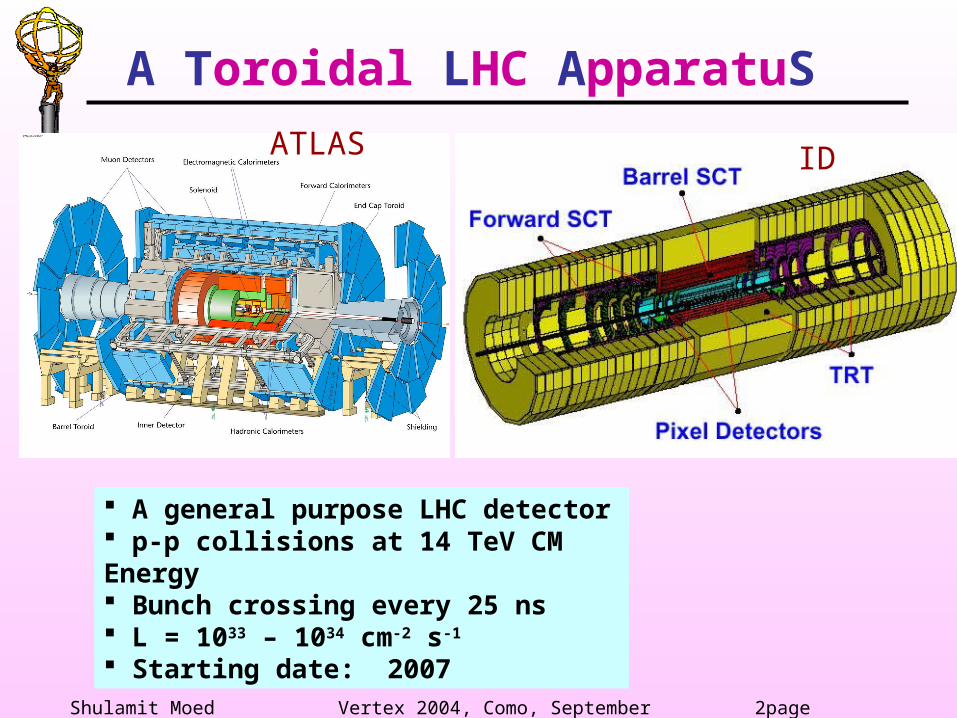
ATLAS ID
A general purpose LHC detector p-p collisions at 14 TeV CM Energy Bunch crossing every 25 ns L = 1033 – 1034 cm-2 s-1
Starting date: 2007
A Toroidal LHC ApparatuS
Shulamit Moed Vertex 2004, Como, September 2004 3page
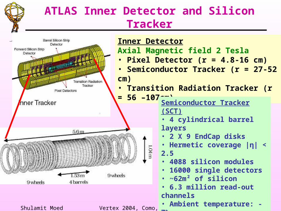
Inner DetectorAxial Magnetic field 2 Tesla• Pixel Detector (r = 4.8-16 cm)• Semiconductor Tracker (r = 27-52 cm)• Transition Radiation Tracker (r = 56 –107cm)
Semiconductor Tracker (SCT)• 4 cylindrical barrel layers • 2 X 9 EndCap disks• Hermetic coverage |η| < 2.5• 4088 silicon modules• 16000 single detectors• ~62m² of silicon• 6.3 million read-out channels• Ambient temperature: -70 • Resolution: - σ (Rφ) = 16 μm - σ (z) = 500 μm
ATLAS Inner Detector and Silicon Tracker
Shulamit Moed Vertex 2004, Como, September 2004 4page
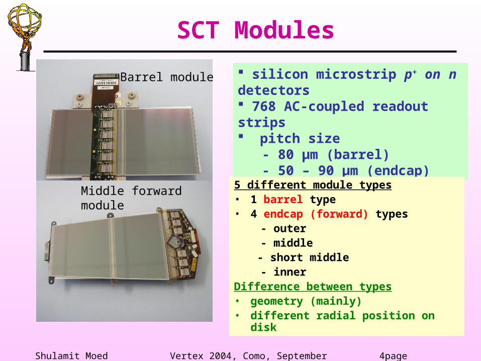
silicon microstrip p+ on n detectors 768 AC-coupled readout strips pitch size - 80 μm (barrel) - 50 – 90 μm (endcap)5 different module types• 1 barrel type• 4 endcap (forward) types - outer - middle
- short middle - inner Difference between types• geometry (mainly)• different radial position on disk
Barrel module
Middle forward module
SCT Modules
Shulamit Moed Vertex 2004, Como, September 2004 5page
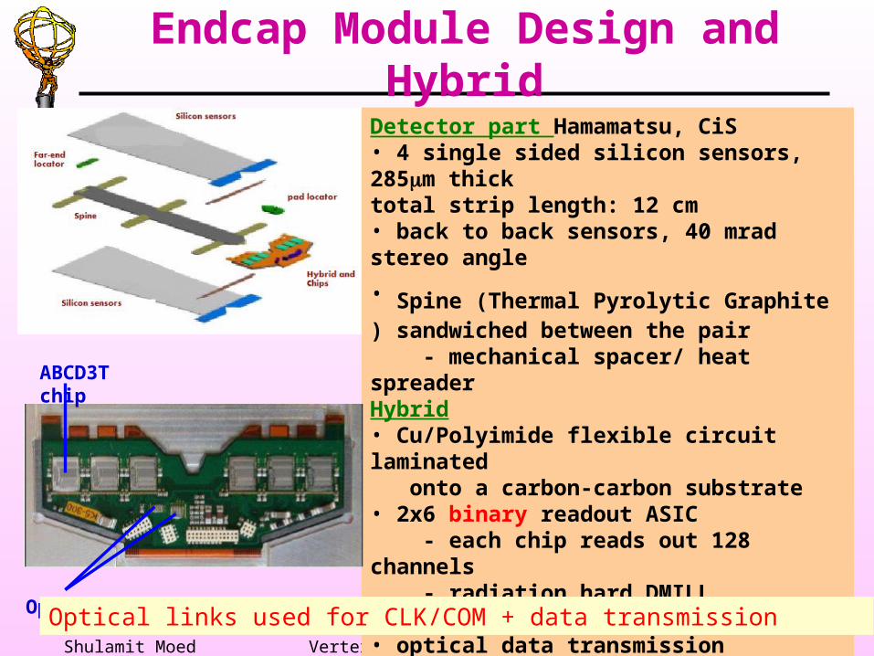
Detector part Hamamatsu, CiS• 4 single sided silicon sensors, 285m thicktotal strip length: 12 cm• back to back sensors, 40 mrad stereo angle
• Spine (Thermal Pyrolytic Graphite ) sandwiched between the pair - mechanical spacer/ heat spreaderHybrid• Cu/Polyimide flexible circuit laminated onto a carbon-carbon substrate• 2x6 binary readout ASIC - each chip reads out 128 channels - radiation hard DMILL technology• optical data transmission• temperature sensors
Opto chip
ABCD3T chip
Optical links used for CLK/COM + data transmission
Endcap Module Design and Hybrid
Shulamit Moed Vertex 2004, Como, September 2004 6page
• Production of the 4088 modules takes place at several sites worldwide– 4 barrel module assembly sites in Japan, Scandinavia,
UK and USA– 7 forward module assembly sites in Australia,
Germany, Netherlands, Spain, Switzerland and the UK • Modules must satisfy many criteria and tolerances – e.g.
– a range of mechanical tolerances, some < 5 m– module leakage current < 80 A at 350V– noise per channel < 1500 ENC (non-irradiated)– average noise occupancy at 1 fC threshold < 5 x 10⁻⁴
– < 1% bad channels
Module Production
Extensive quality assurance
Shulamit Moed Vertex 2004, Como, September 2004 7page
Geneva: Production of ~630 outer EndCap modules (to be shipped to CERN for quality assurance).
Lab with clean room facilities and infrastructure - controlled access - temperature and humidity control - personnel: smocks, hairnets, (antistatic) slippers,
face mask - antistatic stations (floor and bench mats) - clean room with temperature (21±1)º and humidity
(40±5)% control, class 1000
Classify the modules (according to specifications) as: - good/pass/fail/hold - rework (wire bonds defects, chips replacement etc)
Production in Geneva (1)
Shulamit Moed Vertex 2004, Como, September 2004 8page
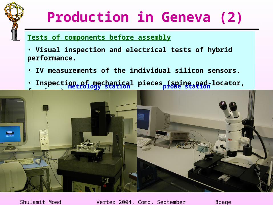
Tests of components before assembly
• Visual inspection and electrical tests of hybrid performance.
• IV measurements of the individual silicon sensors.
• Inspection of mechanical pieces (spine,pad-locator, fan-ins…)
probe station
Production in Geneva (2)
metrology station
Shulamit Moed Vertex 2004, Como, September 2004 9page
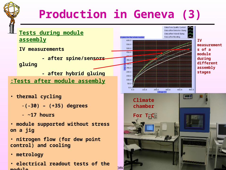
Tests during module assembly
IV measurements
- after spine/sensors gluing
- after hybrid gluing
- after wire bondingTests after module assembly:
• thermal cycling
-(-30) – (+35) degrees
- ~17 hours
• module supported without stress on a jig
• nitrogen flow (for dew point control) and cooling
• metrology
• electrical readout tests of the module
IV measurements of a module during different assembly stages
Climate chamber
For T.C
Production in Geneva (3)
Shulamit Moed Vertex 2004, Como, September 2004 10page
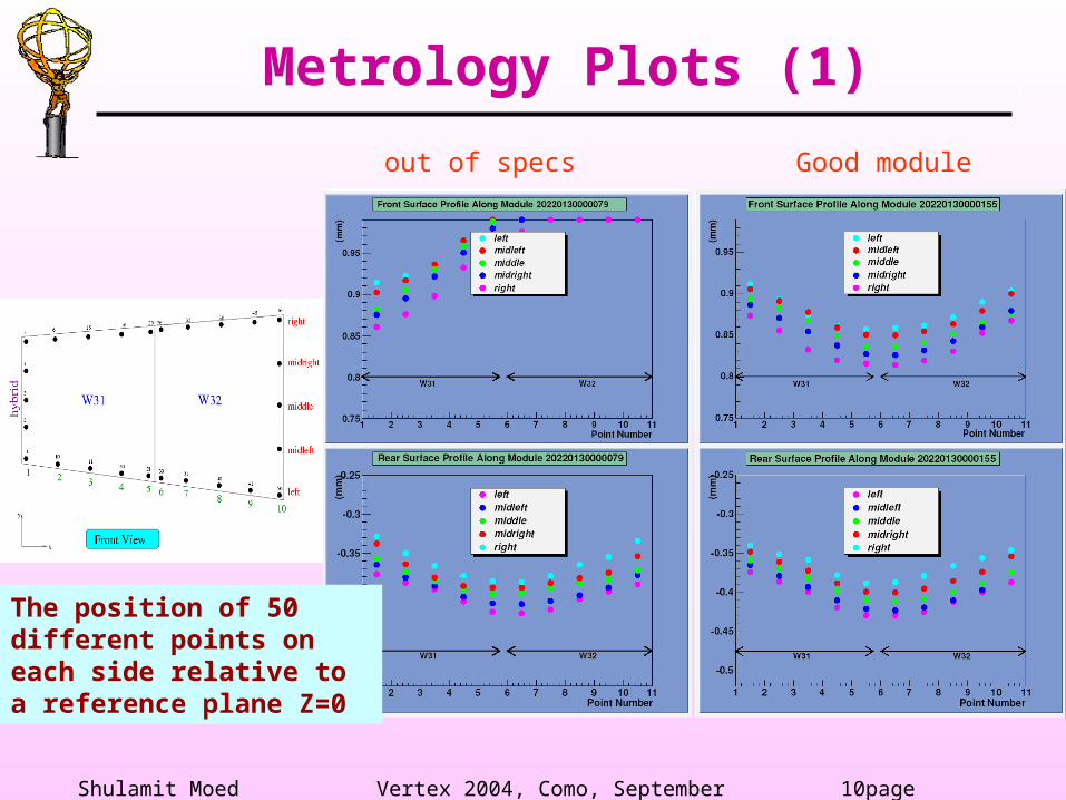
Metrology Plots (1)
The position of 50 different points on each side relative to a reference plane Z=0
out of specs Good module
Shulamit Moed Vertex 2004, Como, September 2004 11page
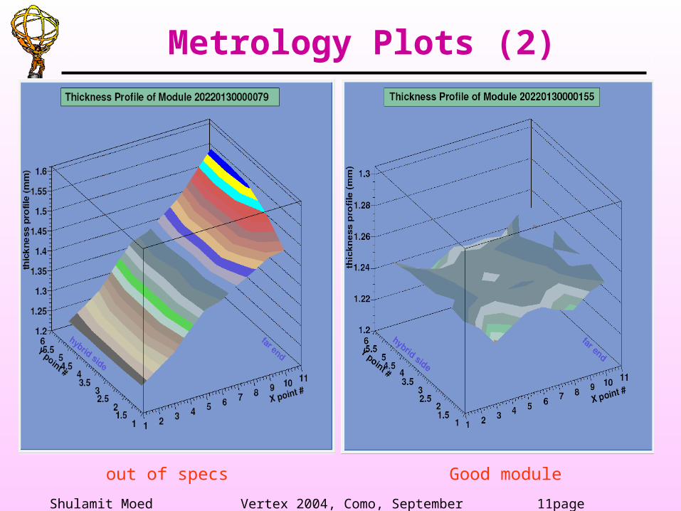
Metrology Plots (2)
Good moduleout of specs

Shulamit Moed Vertex 2004, Como, September 2004 12page
Z profile distributions:
• thickness
• rear Z (50 points)
• front Z (50 points)
Metrology Plots (3)
Well Within Specifications!
Summary of modules produced so far
Shulamit Moed Vertex 2004, Como, September 2004 13page
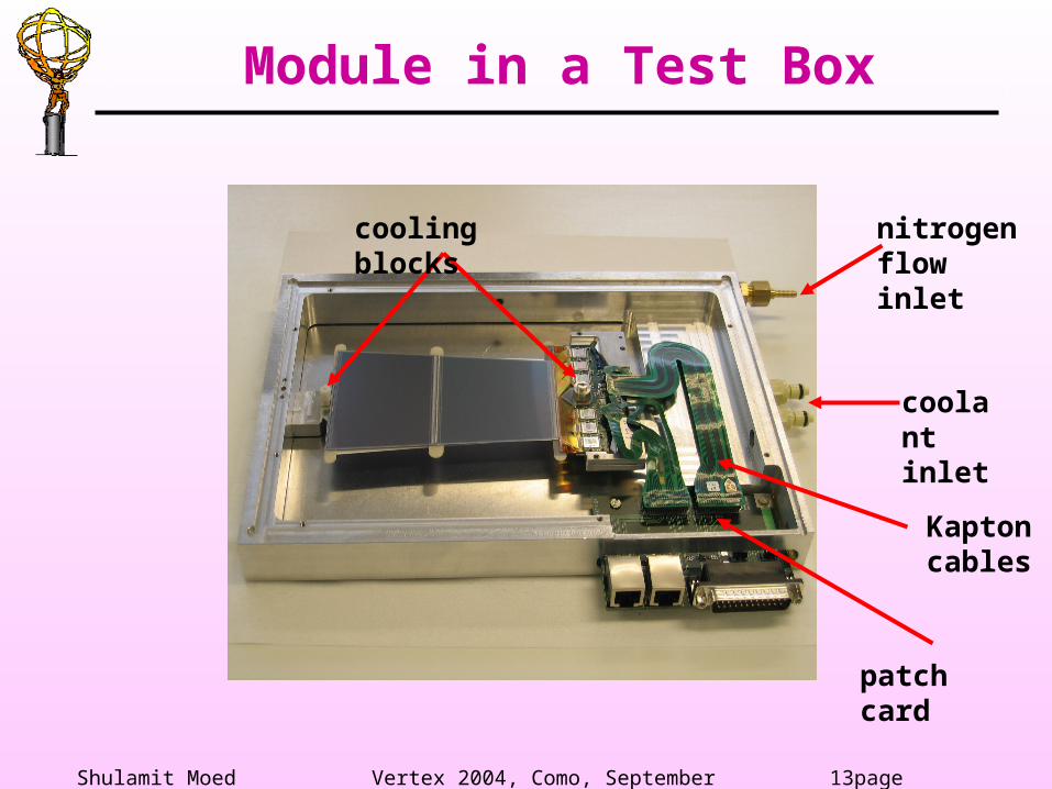
nitrogen flow inlet
coolant inlet
Kapton cables
patch card
cooling blocks
Module in a Test Box
Shulamit Moed Vertex 2004, Como, September 2004 14page
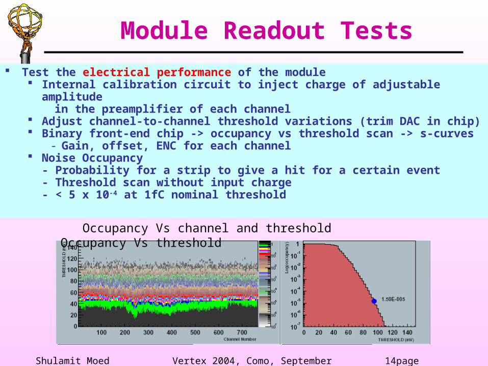
Test the electrical performance of the module Internal calibration circuit to inject charge of adjustable amplitude in the preamplifier of each channel Adjust channel-to-channel threshold variations (trim DAC in chip) Binary front-end chip -> occupancy vs threshold scan -> s-curves
- Gain, offset, ENC for each channel Noise Occupancy
- Probability for a strip to give a hit for a certain event- Threshold scan without input charge- < 5 x 10⁻⁴ at 1fC nominal threshold
Occupancy Vs channel and threshold Occupancy Vs threshold
Module Readout Tests
Shulamit Moed Vertex 2004, Como, September 2004 15page
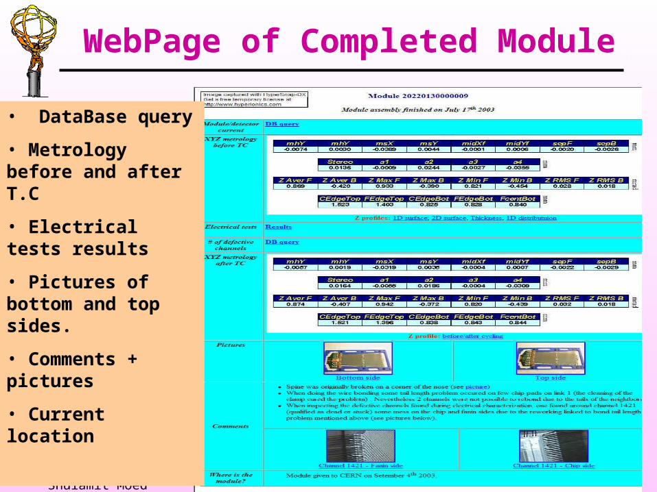
• DataBase query
• Metrology before and after T.C
• Electrical tests results
• Pictures of bottom and top sides.
• Comments + pictures
• Current location
WebPage of Completed Module
Shulamit Moed Vertex 2004, Como, September 2004 16page
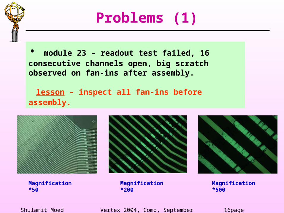
Problems (1)
• module 23 – readout test failed, 16 consecutive channels open, big scratch observed on fan-ins after assembly.
lesson – inspect all fan-ins before assembly.
Magnification *50
Magnification *200
Magnification *500
Shulamit Moed Vertex 2004, Como, September 2004 17page
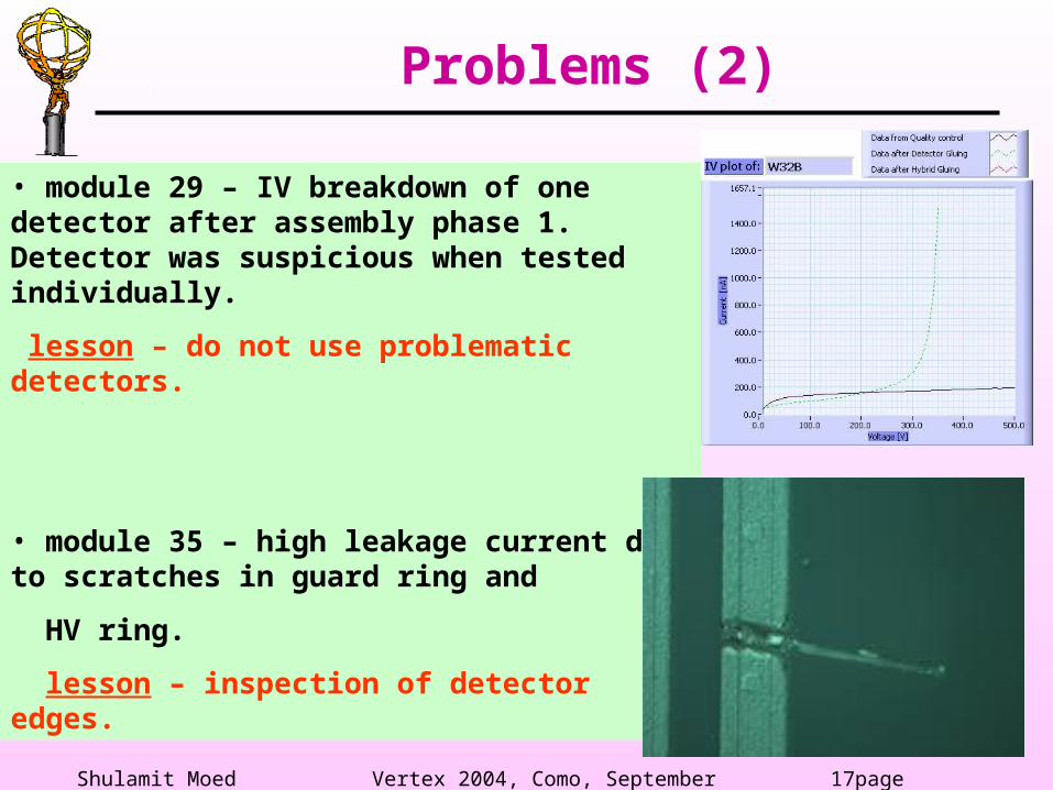
Problems (2)
• module 29 – IV breakdown of one detector after assembly phase 1. Detector was suspicious when tested individually.
lesson – do not use problematic detectors.
• module 35 – high leakage current due to scratches in guard ring and
HV ring.
lesson – inspection of detector edges.
Shulamit Moed Vertex 2004, Como, September 2004 18page
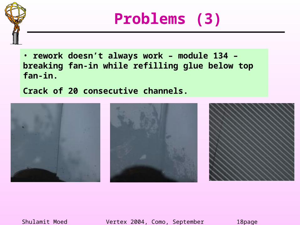
Problems (3)
• rework doesn’t always work – module 134 – breaking fan-in while refilling glue below top fan-in.
Crack of 20 consecutive channels.
Shulamit Moed Vertex 2004, Como, September 2004 19page
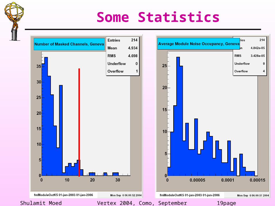
Some Statistics
Shulamit Moed Vertex 2004, Como, September 2004 20page
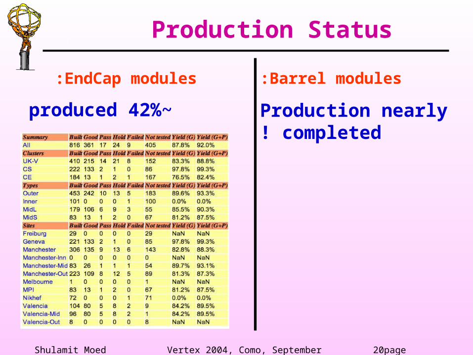
Production Status
Barrel modules:
Production nearly completed!
EndCap modules:
~42% produced
Shulamit Moed Vertex 2004, Como, September 2004 21page
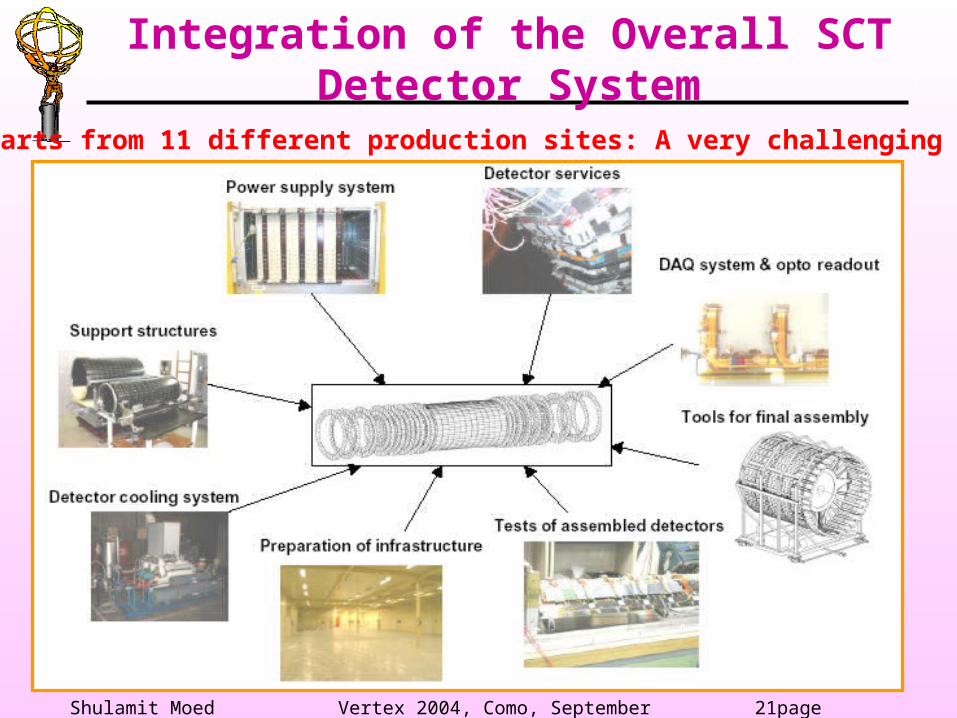
Integration of the Overall SCT Detector System
Parts from 11 different production sites: A very challenging task!
Shulamit Moed Vertex 2004, Como, September 2004 22page
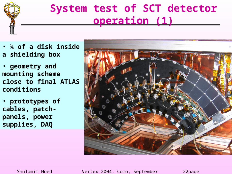
System test of SCT detector operation (1)
• ¼ of a disk inside a shielding box
• geometry and mounting scheme close to final ATLAS conditions
• prototypes of cables, patch-panels, power supplies, DAQ
Shulamit Moed Vertex 2004, Como, September 2004 23page
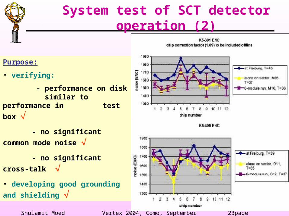
System test of SCT detector operation (2)
Purpose:
• verifying:
- performance on disk similar to
performance in test
box
- no significant
common mode noise
- no significant cross-
talk • developing good grounding
and shielding
Shulamit Moed Vertex 2004, Como, September 2004 24page
Summary
• The ATLAS SCT will be a substantial part of the ATLAS inner detector.
• Production and tests so far have demonstrated that the mechanical precisions can be met with sufficient yield.
• The electrical performance of modules in our production is according to the design specifications.
• Production is almost completed for barrel modules and is well underway for the EndCap modules.
• Electrical tests of the completed barrels and disks and the integration into the ID is still a major effort.
Shulamit Moed Vertex 2004, Como, September 2004 25page
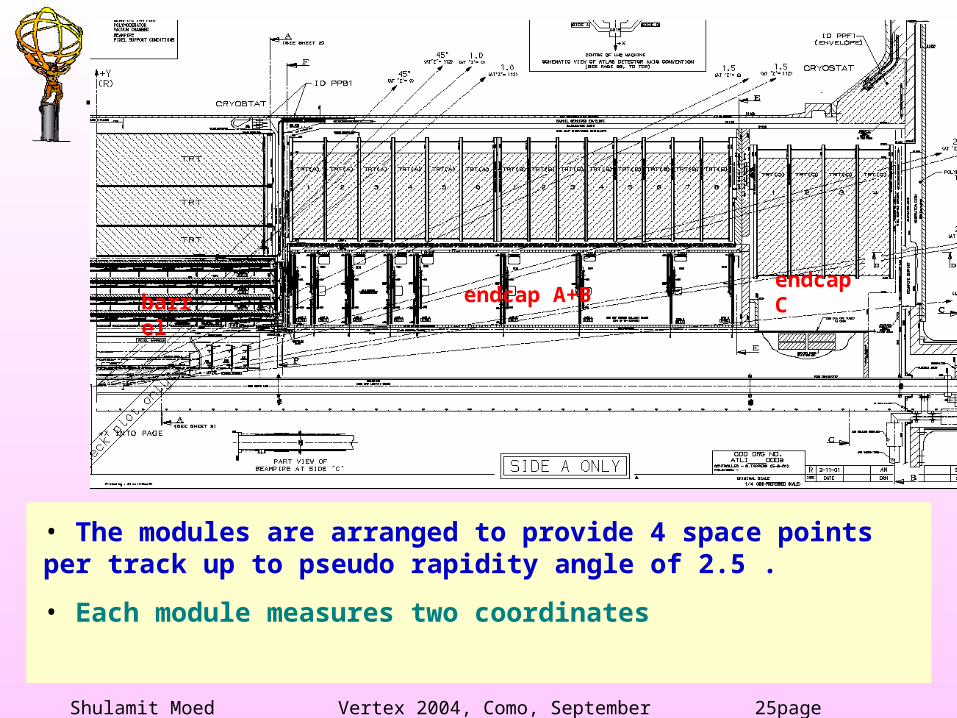
• The modules are arranged to provide 4 space points per track up to pseudo rapidity angle of 2.5 .
• Each module measures two coordinates
barrel endcap A+Bendcap C
Shulamit Moed Vertex 2004, Como, September 2004 26page
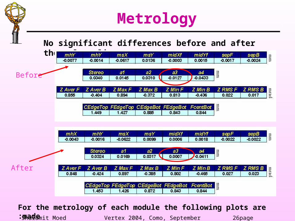
No significant differences before and after thermal cycling
Before
After
For the metrology of each module the following plots are made:
Metrology
Shulamit Moed Vertex 2004, Como, September 2004 27page
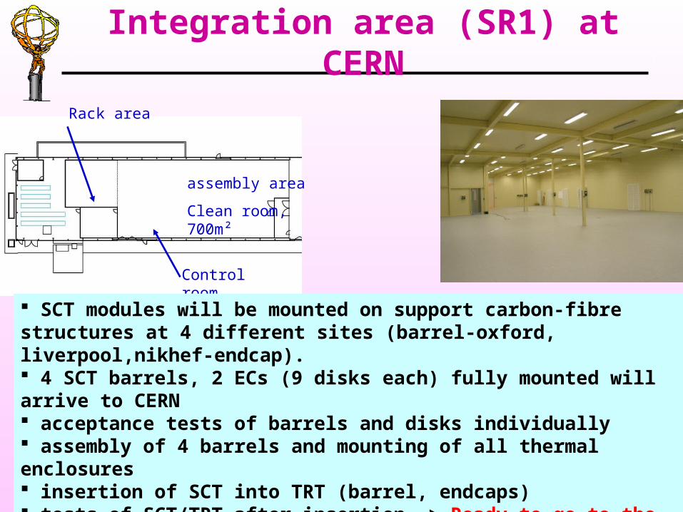
Integration area (SR1) at CERN
assembly area
Clean room, 700m²
Rack area
Control room
SCT modules will be mounted on support carbon-fibre structures at 4 different sites (barrel-oxford, liverpool,nikhef-endcap). 4 SCT barrels, 2 ECs (9 disks each) fully mounted will arrive to CERN acceptance tests of barrels and disks individually assembly of 4 barrels and mounting of all thermal enclosures insertion of SCT into TRT (barrel, endcaps) tests of SCT/TRT after insertion -> Ready to go to the pit!
Shulamit Moed Vertex 2004, Como, September 2004 28page
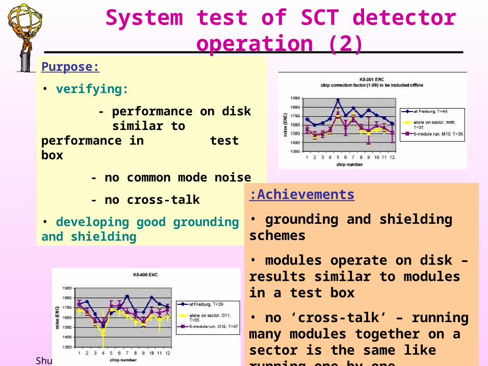
System test of SCT detector operation (2)
Purpose:
• verifying:
- performance on disk similar to performance
in test box
- no common mode noise
- no cross-talk
• developing good grounding and shielding
Achievements:
• grounding and shielding schemes
• modules operate on disk – results similar to modules in a test box
• no ‘cross-talk’ – running many modules together on a sector is the same like running one by one.
Shulamit Moed Vertex 2004, Como, September 2004 29page
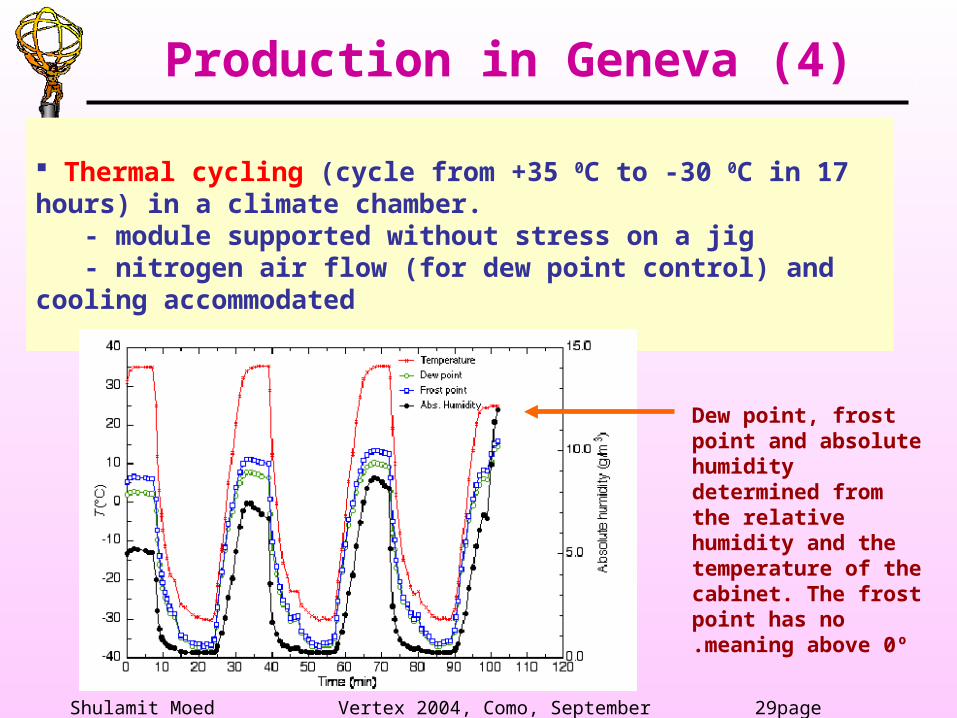
Thermal cycling (cycle from +35 0C to -30 0C in 17 hours) in a climate chamber. - module supported without stress on a jig - nitrogen air flow (for dew point control) and cooling accommodated
Production in Geneva (4)
Dew point, frost point and absolute humidity determined from the relative humidity and the temperature of the cabinet. The frost point has no meaning above 0º.

Shulamit Moed Vertex 2004, Como, September 2004 30page
The Integration timescale
Shulamit Moed Vertex 2004, Como, September 2004 31page
Extensive QA tests on all components- before module assembly- after module assembly (module QA)
Green light for production from the SCT steering group requires: pre-qualification procedure (2 pre-qual. modules, results on web) qualification procedure (5 qual. modules, results on web and SCT database)
The QA procedures are well documented Qualified EndCap production sites: (Freiburg, Geneva/CERN, MPI Munich/Prague, NIKHEF, UK north, Valencia)
Quality Assurance
Shulamit Moed Vertex 2004, Como, September 2004 32page
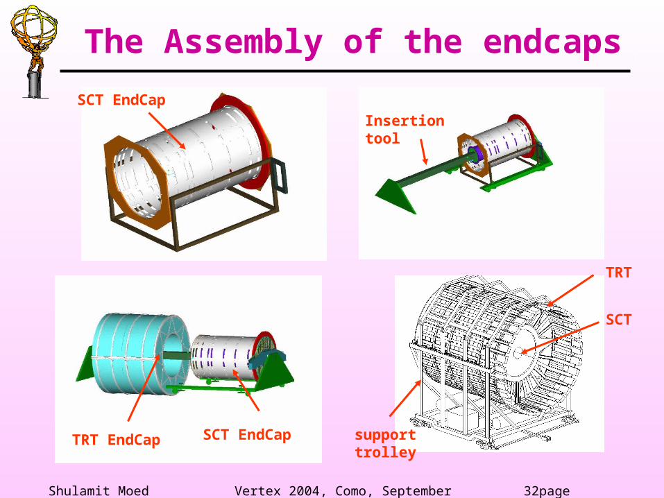
The Assembly of the endcaps
TRT EndCap
SCT EndCap support trolley
SCT
TRT
Insertion toolSCT EndCap


