Shotcrete Rehabilitation of a Vancouver, BC Historic
by R. Heere, D.R. Morgan, N. McAskill,
and T. Knowlton
10
High Rise Building A heritage high-rise building in Vancouver,
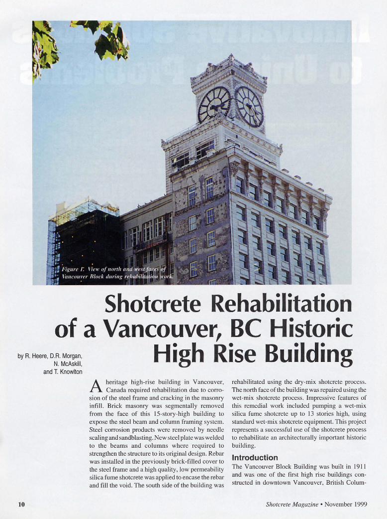
Canada required rehabilitation due to corrosion of the steel frame and cracking in the masonry infill. Brick masonry was segmentally removed from the face of this 15-story-high building to expose the steel beam and column framing system. Steel corrosion products were removed by needle scaling and sandblasting. New steel plate was welded to the beams and columns where required to strengthen the structure to its original design. Rebar was installed in the previously brick-filled cover to the steel frame and a high quality, low permeability silica fume shotcrete was applied to encase the rebar and fill the void. The south side of the building was
rehabilitated using the dry-mix shotcrete process. The north face of the building was repaired using the wet-mix shotcrete process. Impressive features of this remedial work included pumping a wet-mix silica fume shotcrete up to 13 stories high, using standard wet-mix shotcrete equipment. This project represents a successful use of the shotcrete process to rehabilitate an architecturally important historic building.
Introduction The Vancouver Block Building was built in 1911 and was one of the first high rise buildings constructed in downtown Vancouver, British Colum-
Shotcrete Magazine • November 1999

bia, Canada. It is a steel-framed structure with stucco c lad brick masonry walls on the north and south sides of the building, and architectural terracotta hollow brick cladding on the east and west sides of the building. The building has an H-shaped footprint of approximately 22m by 30m (72ft by 98ft). With 15 floors and a central clock tower, the building rises to approx imately 65 m (213ft) above ground level. The building serves as an office building. Figure l shows the north and west elevations of the building.
Deficiencies In earl y 1997, while preparing for paint work, cracks were discovered in the stucco and some terra-cotta elements, which warranted a more detailed investi gation of the building envelope. The owner decided to investigate the causes of the cracking. During the course of thi s investigation, it became apparent that during decades of exposure to wind-driven rain and long periods of high ambient humidity, water had penetrated the stucco and brick masonry. Where such moisture remained in prolonged contact with the structural stee l columns and beams, extensive corrosion occurred. The volume increase of the structural steel elements due to the corrosion widened cracks, which aggravated the moisture penetration problem.
Exploratory removal of brick cladding in selected locations confirmed non-uniform corrosion activity across the facades. While the investigators encountered pristine steel with undisturbed mill sca le on the surface of beams and columns in some locations, in other locations severe corrosion pitting, knife edging, and even complete loss ofl-beam flanges to corrosion was recorded. The overall degree of corrosion was sufficientl y severe to warrant hi ring of a structural consultant to plan the retrofit procedures. Figure 2 shows an example of severe corrosion in a steel column.
Rehabilitation Measures The owner wanted the building to be rehabilitated to a structurally sound and aestheticall y pleasing condition. Chall enging for designer and contractor was the requirement to perform all repair work from the exterior of the building because the structure, which serves as an office building, could not be evacuated during rehabilitat ion. As a consequence, the contractor erected building-high scaffolding covering most areas of the facade on which the work was to be carried out at any given time. Access to areas which were unsuitable for the erection of scaffolding was provided by swing stages.
After erecting the scaffolding and installing the swing stages, work commenced by expos ing the structural stee l. This required removing brick infill where it covered steel columns and beams. The condition of some steel columns warranted temporary shorings in order to reduce the loads during the
Shotcrete Magazine • November 1999
Figure 2. View of corrosion in a steel column prior to repair.
time they were prepared for reinforcement. Figure 3 shows the removal of brick masonry on the south side of the building.
The requirement to conduct all repair work from the outside ofthe building required some innovative designs and construction technology for reinforcing the structural steel elements. In brief, after exposing the structural steel elements and removing corrosion products by needle scaling and sandblasting, customi zed steel profiles were welded to the webs of those beams and columns in need of reinforcement. Figure 4 shows a prepared column with installed new steel plates and rebar prepared for shotcreting.
The initial repair specification for the project
Figure 3. Installed scaffolding and removal of brick masonry on a column line on South face o.l building
11
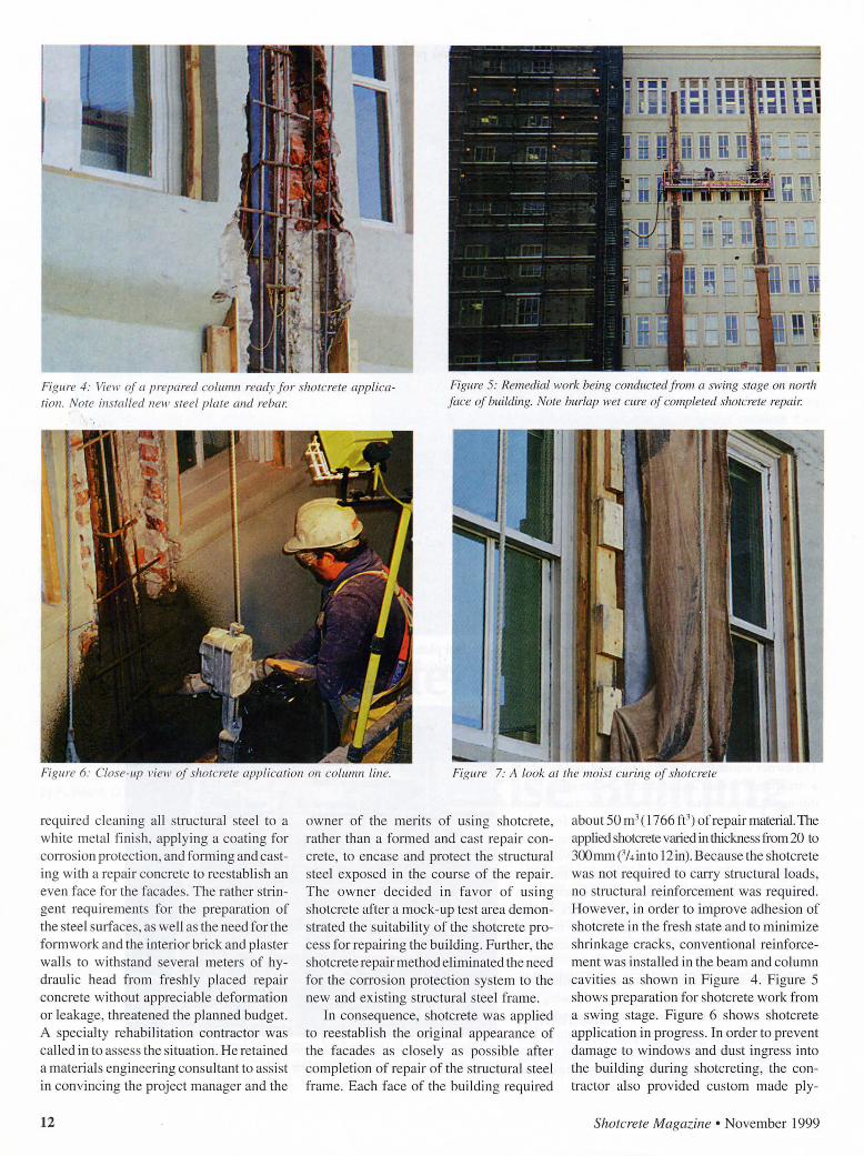
Figure 4: Vie11 · of a prepared column ready for shotcrete application. Note installed new steel plate and rebat:
Figure 5: Remedial work being conductedji'Oin a swing stage on north face of building. Note burlap wet cure of completed shot crete repai1:
Figure 6: Close-up view of shotcrete application on column line. Figure 7: A look at the moist curing of shotcrete
required cleani ng all structural steel to a whi te meta l fi nish, applying a coating for corrosion protection , and forming and casting with a repair concrete to reestabli sh an even face for the facades . The rather stringent requirements for the preparation of the steel sUifaces, as well as the need for the form work and the interior brick and plaster walls to withstand several meters of hydrauli c head fro m freshly placed repair concrete without appreciable deformation or leakage, threatened the planned budget. A specialty rehabilitati on contractor was called in to assess the situation. He retained a materi als engi neering consultant to ass ist in convincing the project manager and the
12
owner of the merits of using shotcrete, rather than a formed and cast repair concrete, to encase and protect the structural steel exposed in the course of the repair. T he owner dec ided in favo r of using shotcrete after a mock-up test area demonstrated the suitability of the shotcrete process for repairing the building. Further, the shotcrete repair method eliminated the need for the corros ion protection system to the new and existing structural steel frame.
In consequence, shotcrete was applied to reestablish the original appearance of the facades as closely as possible after completion of repair of the structural steel frame. Each face of the building required
about 50m3 ( 1766 ft3) of repair mate1ial. The applied shotcrete vmied in thickness from 20 to 300 mm ('14 in to 12 in). Because the shotcrete was not required to carry structural loads, no structural reinfo rcement was required. However, in order to improve adhesion of shotcrete in the fresh state and to minimize shrinkage cracks, conventional reinfo rcement was installed in the beam and column cavities as shown in Figure 4 . Figure 5 shows preparation for shotcrete work from a swing stage. Figure 6 shows shotcrete application in progress . In order to prevent damage to windows and dust ingress into the building during shotcreting, the contractor also provided custom made ply-
Shotcrete Magazine • November 1999
wood shutters for all windows situated in the repair zone.
The initial choice of shotcreting methods was the dry-mix process for its inherent advantages over the wet-mix process, such as greater ease of operation in the stop-and-go mode and lighter equipment to move up and down the scaffolding. The south face of the building was successfully repaired with thi s method. However, the amount of rebound inherent in the dry-mix shotcrete process became a nuisance, because it required frequent removal from the scaffolding. Furthermore, the repair on the north face involved working over a neighboring property which needed to be protected from contamination by shotcrete rebound and overspray.
To address thi s problem, the shotcrete work on the north face was executed using th e wet-mix shotcrete proces s. The shotcrete contractor chose small-line wetmix shotcreting equipment capable of pumping shotcrete the required 15 stories high (50 m) and over approximately 70 m (230ft) horizontally. An adjacent 3-story high parking structure provided a suitable elevated working position for the pump, reducing some of the challenges of delivering shotcrete to all floors of thi s high-rise structure. The wet-mix shotcrete process produced significantly less dust and rebound compared to the dry-mix process employed previously . The use of drybagged premixed shotcrete and careful attention to work preparation and scheduling helped overcome the reduced flexibility of the site mi xed wet-mi x shotcrete method in thi s repair application , which required a stop-and-go procedure.
After cutting and trimming to line and grade and receiving a final trowel finish, the shotcrete sUiface texture blended well into the texture of the surrounding existing stucco finish. Quality control testing by the materials engineering consultant confirmed exce llent hardened properties in the shotcrete. The shotcrete achieved 28-day compressive strengths of between 40 and 50 MPa (5800 and 7250 psi) and values of 4% boiled absorption and 9% volume of permeable voids in testing conducted to ASTM C692. Due to a good moist curing regime with saturated burlap, the shotcrete repairs remained mostly crack-free, though some hairline cracks appeared at shotcretebrick interfaces. Figure 7 shows shotcrete in co lumn moist curing under burlap. This shotcrete is expected to have excellent long
Shotcrete Magazine • November 1999
term durability and provide good corrosion protection to the. rehabilitated structural steel frame.
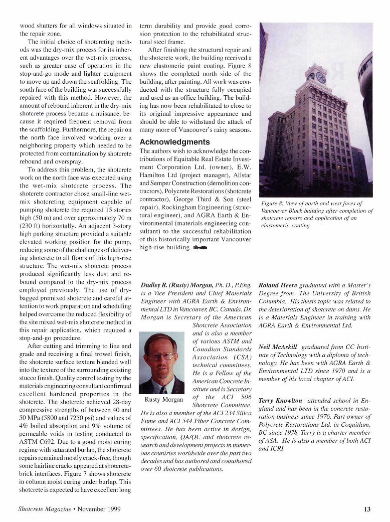
After finishing the structural repair and the shotcrete work , the building received a new elastomeric paint coating. Figure 8 shows the completed north side of the building, after painting. All work was conducted with the structure fully occupied and used as an office building. The building has now been rehabilitated to close to its original impress ive appearance and should be able to withstand the attack of many more of Vancouver's rainy seasons.
Acknowledgments The authors wish to ack nowledge the contributions of Equitable Real Estate Investment Corporation Ltd . (owner) , E.W. Hamilton Ltd (project manager), Allstar and Semper Construction (demolition contractors), Polycrete Restorations (shotcrete contractor) , George Third & Son (steel repair), Rockingham Engineering (structural eng ineer) , and AGRA Earth & Environmental (materi a ls engineering consultant) to the successful rehabilitation of this hi storically important Vancouver hi gh-ri se buildin g.~~
Dudley R. (Rusty) Morgan, Ph. D. , P Eng. is a Vice President and Chief Materials Engineer with AGRA Earth & Environmental LTD in Vancouver, BC, Canada. Dr. Morgan is Secretary of the American
Shotcrete Association and is also a member of various ASTM and Canadian Standards Association (CSA) technical committees. He is a Fellow of the American Concrete Institute and is Secretary
Rusty Morgan of the ACI 506 Shotcrete Committee.
He is also a member of the AC/234 Silica Fume and ACI 544 Fiber Concrete Committees. He has been active in design, specification, QA!QC and shotcrete research and development projects in numerous countries worldwide over the past two decades and has authored and coauthored over 60 shotcrete publications.
Figure 8: View of north and west fa ces of Vancouver Block building after completion of shotcrete repairs and application of an elastomeric coating.
Roland Heere graduated with a Master 's Degree f rom The University of British Columbia. His thesis topic was related to the deterioration of shotcrete on dams. He is a Materials Engineer in training with AGRA Earth & Environmental Ltd.
Neil McAskill graduated from CC Institute ofTechnology with a diploma of technology. He has been with AGRA Earth & Environmental LTD since 1970 and is a member of his local chapter ofAC/.
Terry Knowlton attended school in England and has been in the concrete restoration business since 1976. Part owner of Polycrete Restorations Ltd. in Coquitlam, BC since 1978, Terry is a charter member of ASA. He is also a member of both ACI and ICR!.
13


