Shippensburg University 1871 Old Main Drive
Shippensburg, PA 17257
Central Chilled Water System Evaluation
June 10, 2010
Professional: Entech Engineering, Inc. 4 South Fourth Street P.O. Box 32 Reading, PA 19603 Telephone: 610-373-6667 Fax: 610-373-7537 www.entecheng.com Entech Project #: 2184.32
Shippensburg University Central Chilled Water System
Evaluation
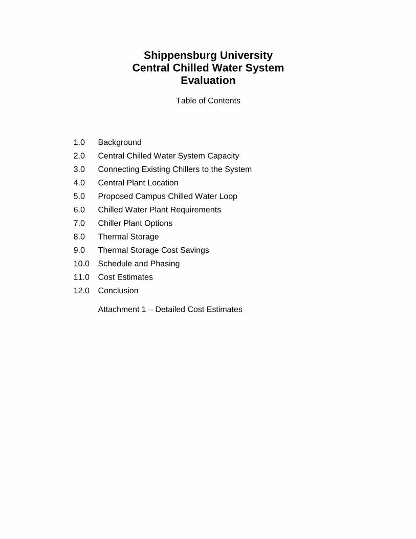
Table of Contents
1.0 Background 2.0 Central Chilled Water System Capacity 3.0 Connecting Existing Chillers to the System 4.0 Central Plant Location 5.0 Proposed Campus Chilled Water Loop 6.0 Chilled Water Plant Requirements 7.0 Chiller Plant Options 8.0 Thermal Storage 9.0 Thermal Storage Cost Savings 10.0 Schedule and Phasing 11.0 Cost Estimates 12.0 Conclusion
Attachment 1 – Detailed Cost Estimates
Entech Engineering, Inc. Page 1
Shippensburg University Central Chilled Water System
1.0 BACKGROUND In 2008, a Utility Master Plan for Shippensburg University was developed as part of the overall Campus Master Plan. One of the more significant recommendations presented in the Campus Master Plan was to replace the existing residence halls with new, air conditioned buildings constructed over a period of three years. The Campus Master Plan also emphasized the importance of implementing energy and environmentally friendly practices. The Utility Master Plan then evaluated various strategies for providing heating and cooling to the campus into the future. Several strategies for providing air conditioning to campus buildings into the future were explored, including the following: Air Conditioning Options
• Continue with “distributed” air conditioning equipment at each building. • Central chilled water. • Ground-source heat pumps for heating and cooling the new residence halls.
In the Utility Master Plan, the Central Chilled Water system was presented as the recommended cooling option for the following reasons: Benefits of Central Chilled Water
• There is economy of scale with larger chilled water equipment. The new residence halls will require substantial cooling equipment which can be more economically installed if it is installed as a central plant rather than cooling equipment installed at each building.
• Building mechanical rooms’ size and cost can be reduced in the proposed residence halls. Cooling tower pumps are located at one site versus having plumes all over Campus.
• Equipment noise and vibration from chillers and cooling towers will be located at the central plant, not within the housing area.
• The central chilled water plant will have back-up equipment, and is therefore more reliable.
• The central plant will have very efficient equipment, reducing energy costs and greenhouse gas emissions.
• It is easier to implement electric load limiting or curtailments with central cooling. • With proper piping design, existing chillers in campus buildings can be connected
to the cooling loop to help provide chilled water to other campus buildings. • With system diversity, the connected cooling equipment in a central cooling
system will be less than what would be installed if each building had its own individual chiller.
• With proper planning, future buildings and renovated buildings can be easily connected to the central cooling system for lower cost.
• Thermal storage, an option for moving cooling and electrical load to off-peak periods, can be more easily installed on a central chilled water system.
Entech Engineering, Inc. Page 2
This study further investigates the feasibility of adding a central chilled water system for the campus. A preliminary design has been prepared to illustrate the recommended system, identify proposed equipment sizes, and develop opinions of probable cost. The option of adding thermal storage is also explored.
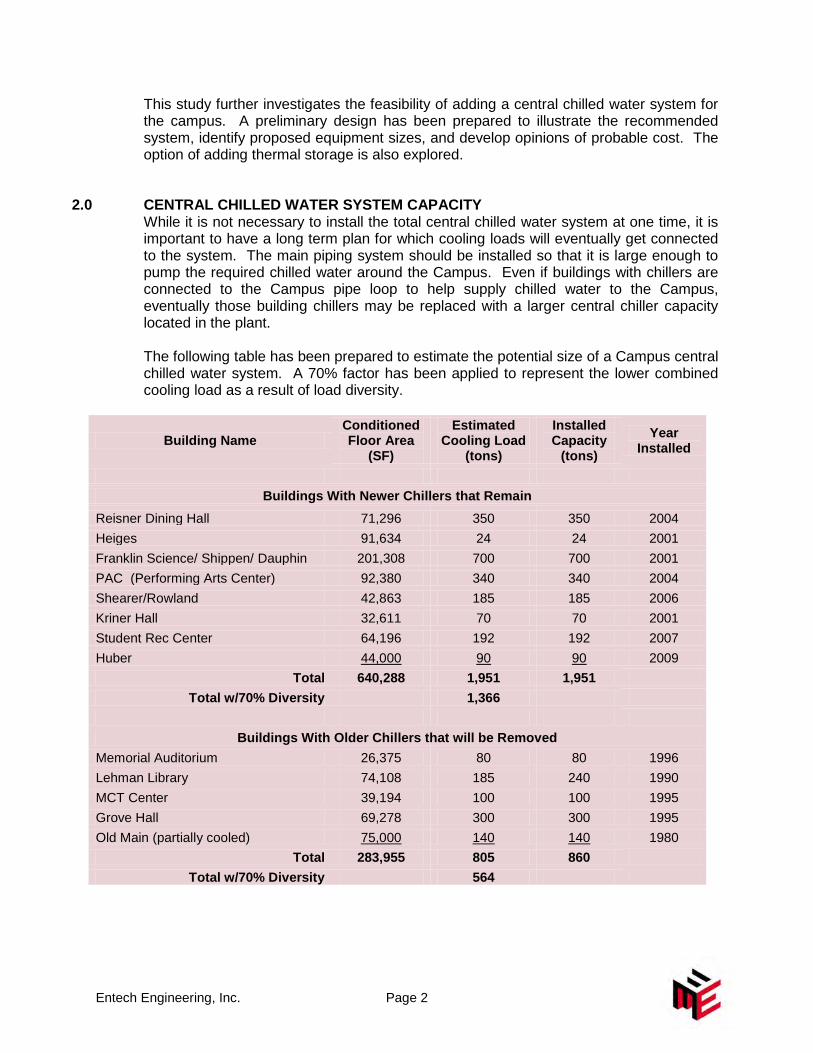
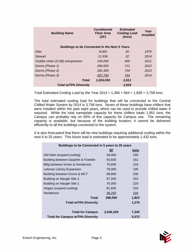
2.0 CENTRAL CHILLED WATER SYSTEM CAPACITY While it is not necessary to install the total central chilled water system at one time, it is important to have a long term plan for which cooling loads will eventually get connected to the system. The main piping system should be installed so that it is large enough to pump the required chilled water around the Campus. Even if buildings with chillers are connected to the Campus pipe loop to help supply chilled water to the Campus, eventually those building chillers may be replaced with a larger central chiller capacity located in the plant. The following table has been prepared to estimate the potential size of a Campus central chilled water system. A 70% factor has been applied to represent the lower combined cooling load as a result of load diversity.
Building Name Conditioned Floor Area
(SF)
Estimated Cooling Load
(tons)
Installed Capacity
(tons)
Year Installed
Buildings With Newer Chillers that Remain
Reisner Dining Hall 71,296 350 350 2004 Heiges 91,634 24 24 2001 Franklin Science/ Shippen/ Dauphin 201,308 700 700 2001 PAC (Performing Arts Center) 92,380 340 340 2004 Shearer/Rowland 42,863 185 185 2006 Kriner Hall 32,611 70 70 2001 Student Rec Center 64,196 192 192 2007 Huber 44,000 90 90 2009
Total 640,288 1,951 1,951 Total w/70% Diversity 1,366
Buildings With Older Chillers that will be Removed
Memorial Auditorium 26,375 80 80 1996 Lehman Library 74,108 185 240 1990 MCT Center 39,194 100 100 1995 Grove Hall 69,278 300 300 1995 Old Main (partially cooled) 75,000 140 140 1980
Total 283,955 805 860 Total w/70% Diversity 564
Entech Engineering, Inc. Page 3
Building Name Conditioned Floor Area
(SF)
Estimated Cooling Load
(tons)
Year Installed
Buildings to be Connected in the Next 5 Years
Etter 9,000 20 1976 Stewart 11,936 32 2014 Ceddia Union (CUB) w/expansion 140,000 400 2011 Dorms (Phase 1) 284,000 711 2012 Dorms (Phase 2) 281,400 704 2013 Dorms (Phase 3) 297,700 744 2014
Total 1,024,036 2,611 Total w/70% Diversity 1,818
Total Estimated Cooling Load by the Year 2014 = 1,366 + 564 + 1,828 = 3,758 tons. The total estimated cooling load for buildings that will be connected to the Central Chilled Water System by 2014 is 3,758 tons. Seven of these buildings have chillers that were installed within the past eight years, which can be used to provide chilled water if required. While the total nameplate capacity for these chillers totals 1,951 tons, the Campus can probably rely on 60% of this capacity for Campus use. The remaining capacity is available, but because of the building location, it cannot be delivered efficiently to all the buildings connected to the system. It is also forecasted that there will be nine buildings requiring additional cooling within the next 5 to 25 years. This future load is estimated to be approximately 1,432 tons.
Buildings to be Connected in 5 years to 25 years SF tons Old Main (expand cooling) 39,000 240 Building between Dauphin & Franklin 55,600 161 Bldg between Kriner & Henderson 75,600 218 Lehman Library Expansion 78,000 195 Building between Grove & MCT 68,800 200 Building on Naugle Site-1 87,200 252 Building on Naugle Site-1 76,000 220 Heiges (expand cooling) 81,600 233 Henderson 36,250 104
Total 398,050 1,823 Total w/70% Diversity 1,276
Total for Campus 2,546,329 7,245
Total for Campus w/70% Diversity 5,072
Entech Engineering, Inc. Page 4
Based on this chilled water load summary, the total Central Chilled Water System should be sized to handle approximately 5,072 tons (3,744 tons + 1,328 tons). The target sizing for the plant is 4,800 tons with the residual amount to be supported/ offset by Campus building chillers as needed. The mains coming out of the plant are intended to be 20”, which can handle approximately 5,000 tons at a 12°F temperature differential and even more at higher ΔT’s. If the main chilled water pipe is 20-inch, then the chilled water flow can be as high as 10,000 gpm.
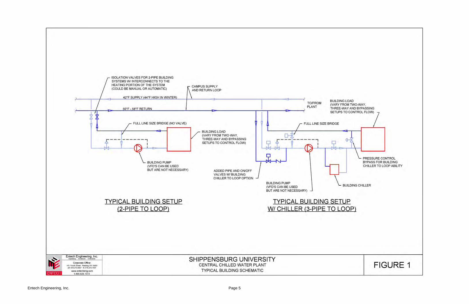
3.0 CONNECTING EXISTING CHILLERS TO THE SYSTEM With proper piping design, it is possible to connect existing building chillers to the chilled water pipe loop that will be installed on the Campus. In order for a building chiller to be able to supply chilled water to the campus loop, three pipes must be installed between the building and the pipe loop. The simple flow diagram, Figure 1 found on the following page, illustrates a typical bridge arrangement for all the buildings, and it also shows the added third pipe needed to incorporate a building chiller that could “export” chilled water to the central loop. Because the chilled water supplied by the chillers must enter the Campus supply pipe before it reaches the buildings with the cooling load, it is best to have the building chillers that supply chilled water to the loop be located as close to the central plant as possible. If it is located further away, the equipment cannot be relied upon to provide the total chiller capacity to other buildings where the cooling load is located. The CUB chiller is not included on this list. Because the timing on the Central Chilled Water System is close to the completion of the CUB Renovation Project, a new 500 ton air-cooled chiller is being installed at CUB on a temporary basis until the central plant is operational. The CUB chiller can then be relocated to the Central Chilled Water Plant. The CUB chiller will be an air cooled chiller that can later provide the smaller amount of chilled water needed during periods of colder weather when tower freezing is a problem for water cooled chillers.
Entech Engineering, Inc. Page 5
Entech Engineering, Inc. Page 6
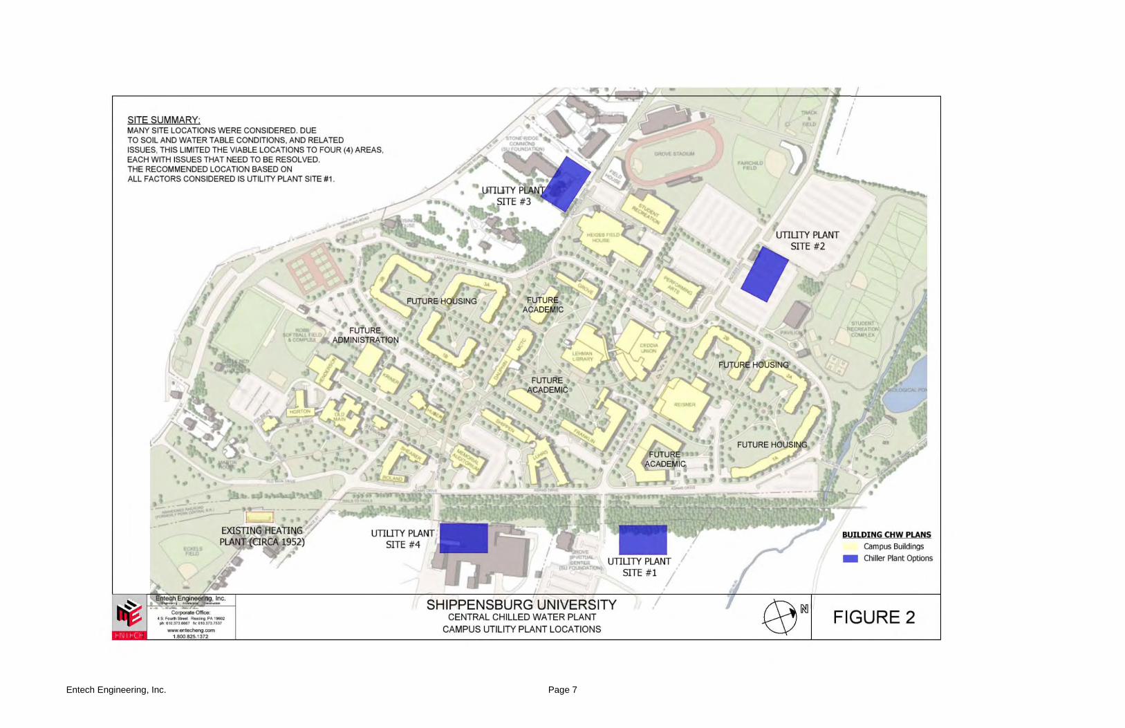
4.0 CENTRAL PLANT LOCATION Various site locations for the proposed Central Chilled Water Plant have been evaluated. The central plant will contain the main chillers and pumps for the system. Factors that must be considered when selecting a plant location are as follows:
• The plant should be located as close to the Campus chilled water loads as possible in order to reduce piping costs and minimize pumping costs.
• Because the plant will contain large, noisy equipment, it should be located away from other buildings as much as possible.
• There are benefits if the chilled water plant is located adjacent to the Campus heating plant. The existing plant is not ideal from a distance standpoint, and would add significant construction costs, and of course add to the pumping costs. The existing plant does not have the space to accommodate chillers and construction in the area is limited. If together, the plant operators could more easily supervise both heating and cooling operations. Also, building spaces (shops, storage, chemical storage, loading/unloading, etc.) can serve both heating and cooling operations rather than having duplicate spaces if the operations are split.
• Because the plant will require truck traffic (plant deliveries, maintenance trucks, etc) it is better to locate the facility outside of the Campus, away from heavy pedestrian traffic.
• There must be sufficient space to locate cooling towers. As discussed later in this report, there is also an opportunity to use thermal storage for the chilled water system. Consequently, there must be space to be able to erect a large, pad-mounted storage tank.
• The site must be available for this function.
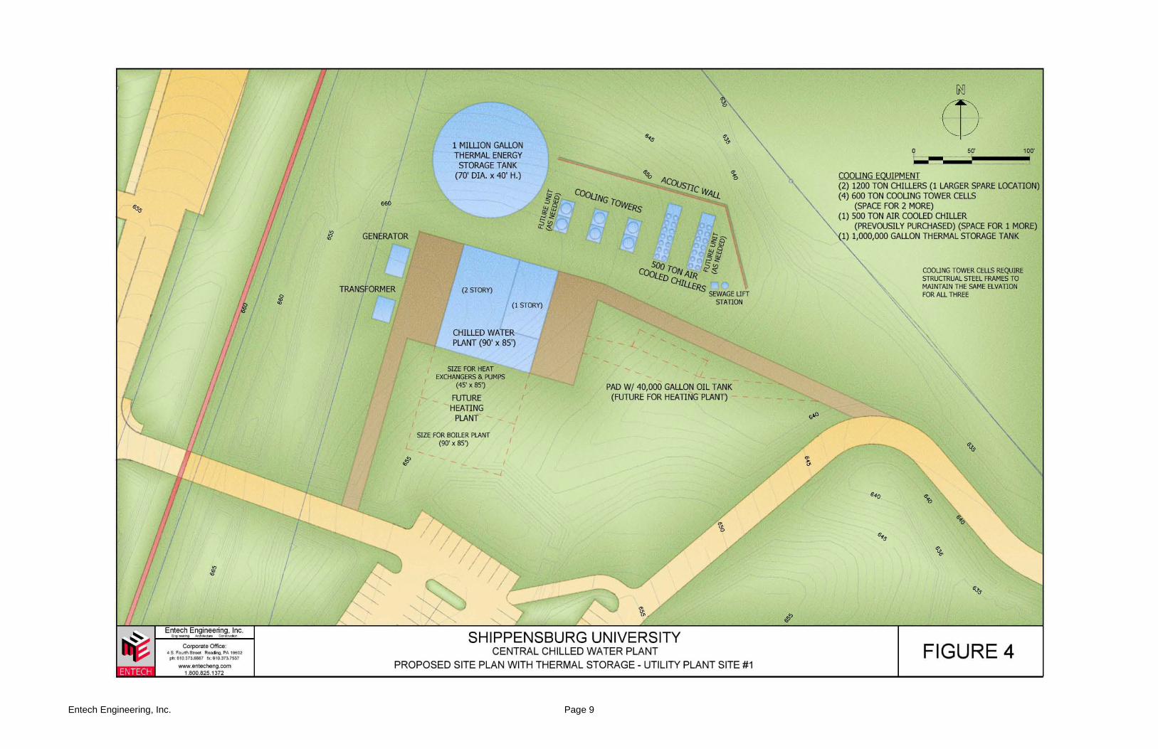
A number of possible plant locations were evaluated on campus. The possible plant locations investigated are shown in Figure 2 on the following page. However, based on the factors described above, the recommended location for the central plant is on the wooded area located across from the Spiritual Center. This land is presently owned by the Foundation. The site plan on the next page, Figure 3, identifies the preferred building location. Figure 4 is the same area layout with a thermal energy storage (TES) tank.
Entech Engineering, Inc. Page 7

Entech Engineering, Inc. Page 8
Entech Engineering, Inc. Page 9
Entech Engineering, Inc. Page 10
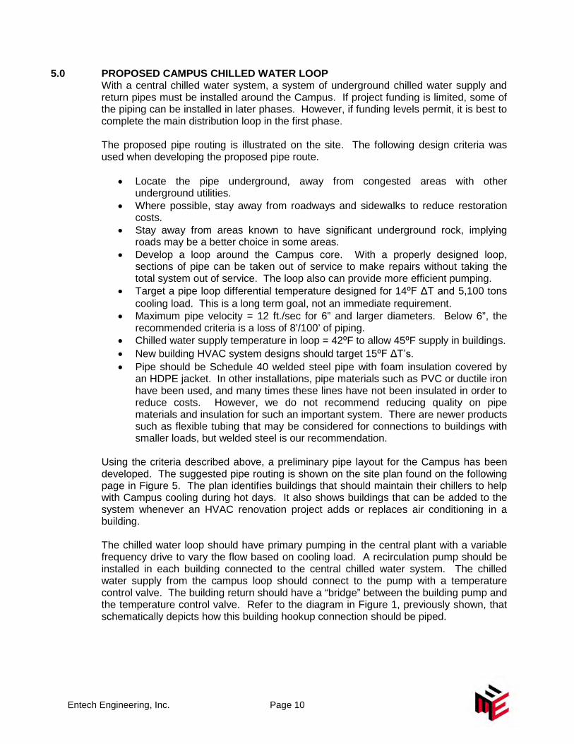
5.0 PROPOSED CAMPUS CHILLED WATER LOOP With a central chilled water system, a system of underground chilled water supply and return pipes must be installed around the Campus. If project funding is limited, some of the piping can be installed in later phases. However, if funding levels permit, it is best to complete the main distribution loop in the first phase. The proposed pipe routing is illustrated on the site. The following design criteria was used when developing the proposed pipe route.
• Locate the pipe underground, away from congested areas with other underground utilities.
• Where possible, stay away from roadways and sidewalks to reduce restoration costs.
• Stay away from areas known to have significant underground rock, implying roads may be a better choice in some areas.
• Develop a loop around the Campus core. With a properly designed loop, sections of pipe can be taken out of service to make repairs without taking the total system out of service. The loop also can provide more efficient pumping.
• Target a pipe loop differential temperature designed for 14⁰F ΔT and 5,100 tons cooling load. This is a long term goal, not an immediate requirement.
• Maximum pipe velocity = 12 ft./sec for 6” and larger diameters. Below 6”, the recommended criteria is a loss of 8’/100’ of piping.
• Chilled water supply temperature in loop = 42⁰F to allow 45⁰F supply in buildings. • New building HVAC system designs should target 15⁰F ΔT’s. • Pipe should be Schedule 40 welded steel pipe with foam insulation covered by
an HDPE jacket. In other installations, pipe materials such as PVC or ductile iron have been used, and many times these lines have not been insulated in order to reduce costs. However, we do not recommend reducing quality on pipe materials and insulation for such an important system. There are newer products such as flexible tubing that may be considered for connections to buildings with smaller loads, but welded steel is our recommendation.
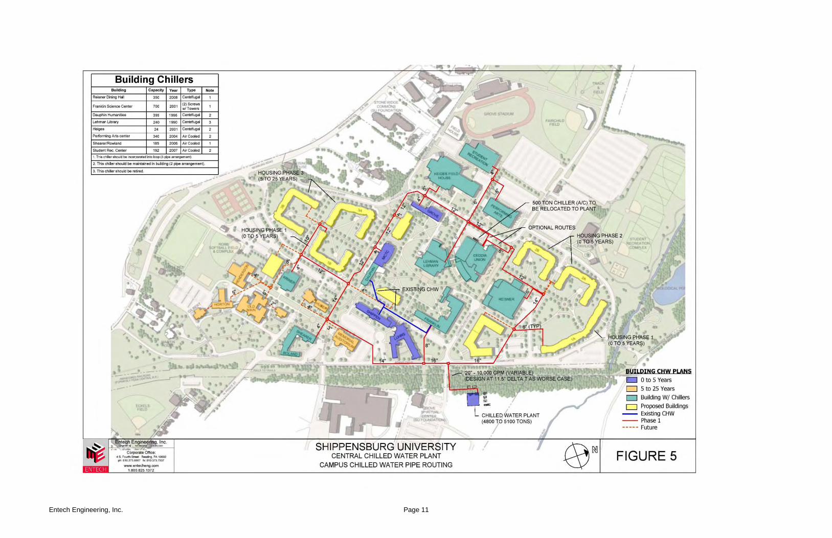
Using the criteria described above, a preliminary pipe layout for the Campus has been developed. The suggested pipe routing is shown on the site plan found on the following page in Figure 5. The plan identifies buildings that should maintain their chillers to help with Campus cooling during hot days. It also shows buildings that can be added to the system whenever an HVAC renovation project adds or replaces air conditioning in a building. The chilled water loop should have primary pumping in the central plant with a variable frequency drive to vary the flow based on cooling load. A recirculation pump should be installed in each building connected to the central chilled water system. The chilled water supply from the campus loop should connect to the pump with a temperature control valve. The building return should have a “bridge” between the building pump and the temperature control valve. Refer to the diagram in Figure 1, previously shown, that schematically depicts how this building hookup connection should be piped.
Entech Engineering, Inc. Page 11
Entech Engineering, Inc. Page 12
The proposed concept incorporates existing underground PVC piping between the Franklin and Shippen/Dauphin buildings. It is assumed that the existing piping is capable of handling 150 psig pressure and this piping should be hydrotested at some point to confirm this. The campus building automation system (BAS) can be expanded to control the chilled water operations. With a web based BAS, the system can be monitored and controlled from almost any location. In most buildings, there should be a central panel for monitoring temperature and flows so Btu’s can be measured at each building. In this time where energy efficiency is critical, measuring energy consumption is vital. If chilled water storage is implemented, understanding and predicting chilled water use and matching it to the chilled water available in the tank will be necessary.
6.0 CHILLED WATER PLANT REQUIREMENTS Should the University proceed with constructing a new heating plant, the building for the central chilled water plant should be combined with the new heating plant building. However, it is possible to construct the chilled water plant as a stand-alone facility. The building should include the following:
• Three electrical driven chillers with space for a fourth (future) chiller. The total plant capacity should be sized for an eventual 4,800 to 5100 tons of cooling. Water cooled centrifugal chillers will see some variable flow.
• Relocate the 500 ton air-cooled chiller from CUB to a pad located outside the chiller building. This will be a lower load, winter use chiller that would likely be brought on last otherwise.
• Space should be provided for an additional 500 ton air-cooled chiller to provide additional cooling in the future.
• The plant should use variable, primary pumping. Primary/secondary piping is more traditional, but not necessary with today’s chillers and control schemes with VFD’s on pumps and chillers.
• Use cooling towers with VFD’s on the tower fans. The towers can be mounted on the building roof or on a slab on-grade. Towers with corrosion resistant materials should be used. Provisions for controlling tower noise should be implemented. VFD’s on condenser water pumps are not necessary.
• The building should include the following: o Sound attenuation o Overhead doors to access and replace large equipment, such as chillers o Control room o Water treatment room o Chemical storage o Maintenance area o Parts storage o Lunch/conference room o Rest rooms o Structure sized to handle plant piping o Electric switchgear room
Entech Engineering, Inc. Page 13
• The building size required is estimated to be approximately 12,000 SF, including second floor offices, etc.
• The electrical distribution service must be upgraded to serve both the new residence halls and the chiller plant. The present plan described in the campus master plan calls for Feeders 1201 and 1202 to be relocated outside of the footprint of the new buildings and the older cable replaced with larger cable to serve the new residence halls and the chiller/boiler plant. The total electric feeder upgrade cost is estimated to be $1.8 million. $1 million is portioned into the cost estimates for the new chiller plant at this time.
7.0 CHILLER PLANT OPTIONS Two options for constructing the first phase of the proposed chilled water plant have been evaluated. The first option is to construct a standard chilled water plant. The second option is to construct a chiller plant with a thermal storage tank. The chillers will produce chilled water during off-peak periods at night when the electric rates are lower and the chiller and cooling tower operate more efficiently. During the day, the tank helps supply chilled water to the campus. In periods of milder weather, it may be possible to provide most of the chilled water from the thermal storage tank during the day.
Option 1 – Standard Chiller Plant
• Two (2) 1,200 ton centrifugal chillers. • One (1) 500 ton air-cooled chiller (relocated from CUB). • Space for one future 1,500 ton chiller. • Space for one future 500 ton air-cooled chiller.
Option 2 – Chiller Plant with Thermal Storage
• Two (2) 900 ton centrifugal chillers. • One (1) 500 ton air-cooled chiller (relocated from CUB). • One (1) 1 million gallon thermal storage tank (800-1,000 ton equivalent). • Space for one future 1,500 ton chiller inside the building. • Space for one future 500 ton air-cooled chiller.
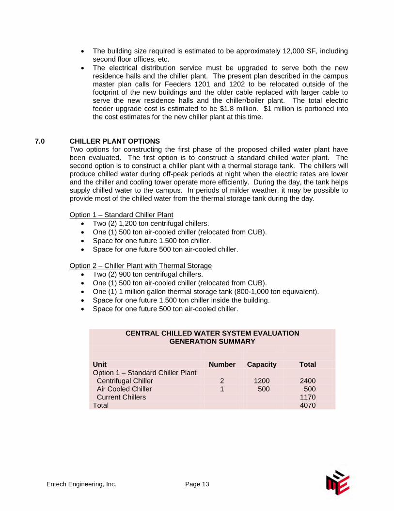
CENTRAL CHILLED WATER SYSTEM EVALUATION GENERATION SUMMARY
Unit Number Capacity Total Option 1 – Standard Chiller Plant Centrifugal Chiller 2 1200 2400 Air Cooled Chiller 1 500 500 Current Chillers 1170 Total 4070
Entech Engineering, Inc. Page 14
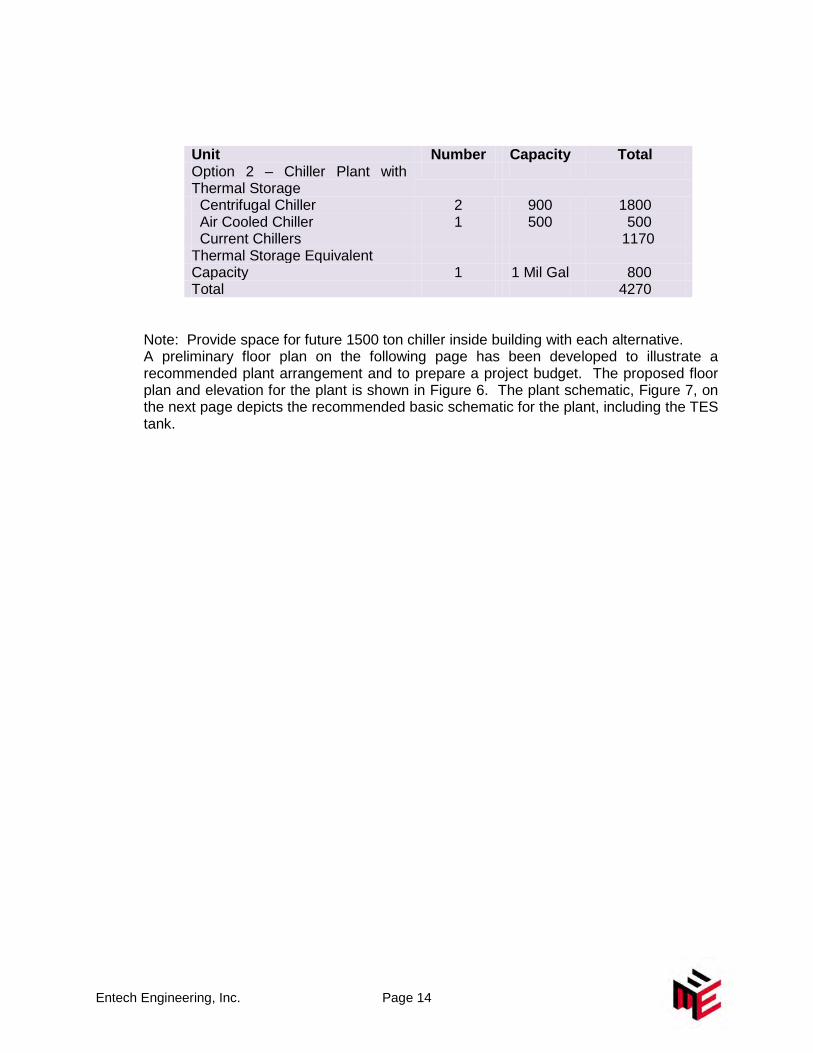
Unit Number Capacity Total Option 2 – Chiller Plant with Thermal Storage
Centrifugal Chiller 2 900 1800 Air Cooled Chiller 1 500 500 Current Chillers 1170 Thermal Storage Equivalent Capacity 1 1 Mil Gal 800 Total 4270
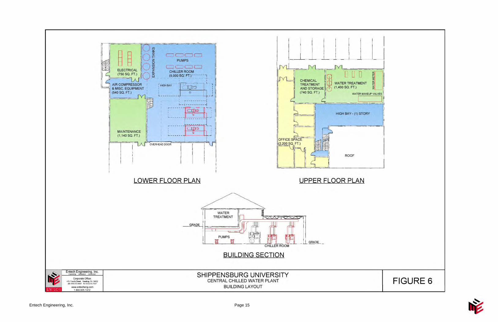
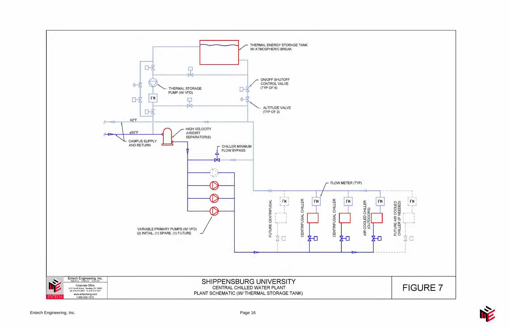
Note: Provide space for future 1500 ton chiller inside building with each alternative. A preliminary floor plan on the following page has been developed to illustrate a recommended plant arrangement and to prepare a project budget. The proposed floor plan and elevation for the plant is shown in Figure 6. The plant schematic, Figure 7, on the next page depicts the recommended basic schematic for the plant, including the TES tank.
Entech Engineering, Inc. Page 15
Entech Engineering, Inc. Page 16
Entech Engineering, Inc. Page 17
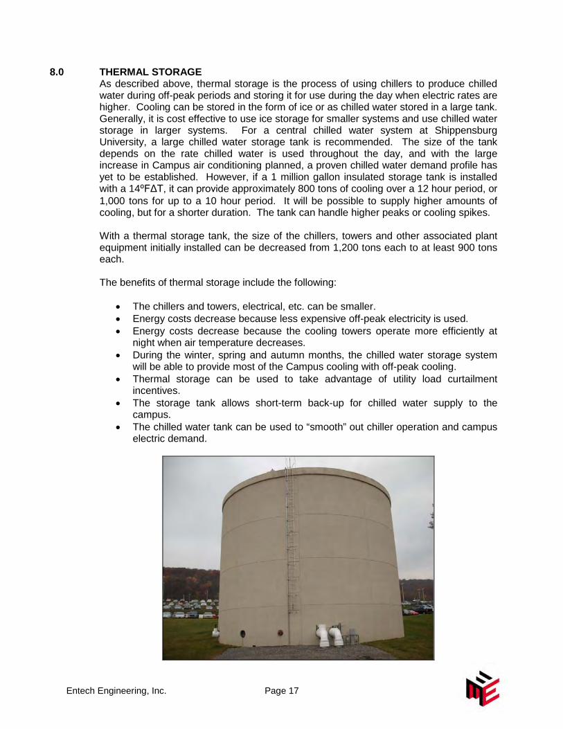
8.0 THERMAL STORAGE As described above, thermal storage is the process of using chillers to produce chilled water during off-peak periods and storing it for use during the day when electric rates are higher. Cooling can be stored in the form of ice or as chilled water stored in a large tank. Generally, it is cost effective to use ice storage for smaller systems and use chilled water storage in larger systems. For a central chilled water system at Shippensburg University, a large chilled water storage tank is recommended. The size of the tank depends on the rate chilled water is used throughout the day, and with the large increase in Campus air conditioning planned, a proven chilled water demand profile has yet to be established. However, if a 1 million gallon insulated storage tank is installed with a 14⁰FΔT, it can provide approximately 800 tons of cooling over a 12 hour period, or 1,000 tons for up to a 10 hour period. It will be possible to supply higher amounts of cooling, but for a shorter duration. The tank can handle higher peaks or cooling spikes. With a thermal storage tank, the size of the chillers, towers and other associated plant equipment initially installed can be decreased from 1,200 tons each to at least 900 tons each. The benefits of thermal storage include the following:
• The chillers and towers, electrical, etc. can be smaller. • Energy costs decrease because less expensive off-peak electricity is used. • Energy costs decrease because the cooling towers operate more efficiently at
night when air temperature decreases. • During the winter, spring and autumn months, the chilled water storage system
will be able to provide most of the Campus cooling with off-peak cooling. • Thermal storage can be used to take advantage of utility load curtailment
incentives. • The storage tank allows short-term back-up for chilled water supply to the
campus. • The chilled water tank can be used to “smooth” out chiller operation and campus
electric demand.

Entech Engineering, Inc. Page 18
9.0 THERMAL STORAGE COST SAVINGS As mentioned above, the thermal storage tank allows the campus chillers to shift some of the load to night time periods when electric rates are lower and ambient temperatures cooler. By maximizing the use of the thermal storage tank, we estimate the billing demand will be reduced as follows:
Month kW Reduction January 0 February 0 March 200 April 500 May 1,000 June 1,000 July 1,000 August 1,000 September 1,000 October 1,000 November 500 December 200 Total 7,400
After the rate caps are eliminated in 2011, we estimate the billing demand charge will be approximately $8.30/kW. At this cost rate, the demand savings is expected to be $61,420. The chillers will also operate at night when the tank is being recharged. Because the condensers are operating at a cooler temperature, we expect a 15% improvement in efficiency. Over the course of the year, we estimate the performance improvement will decrease electric consumption by approximately 300,000 kWh/yr. Using a projected electric rate of $0.104/kWh after the rate caps are removed, the savings will be $31,650. Therefore, the total electric savings in the first year will be $93,000 ($61,000 + $ 32,000). With electric power deregulation in Pennsylvania, the University will have more opportunity for reducing its electric bill by controlling power consumption using techniques such as thermal storage. It is anticipated the cost savings using the storage tank will increase, perhaps significantly, in coming years, and the payback period will decrease.
Entech Engineering, Inc. Page 19
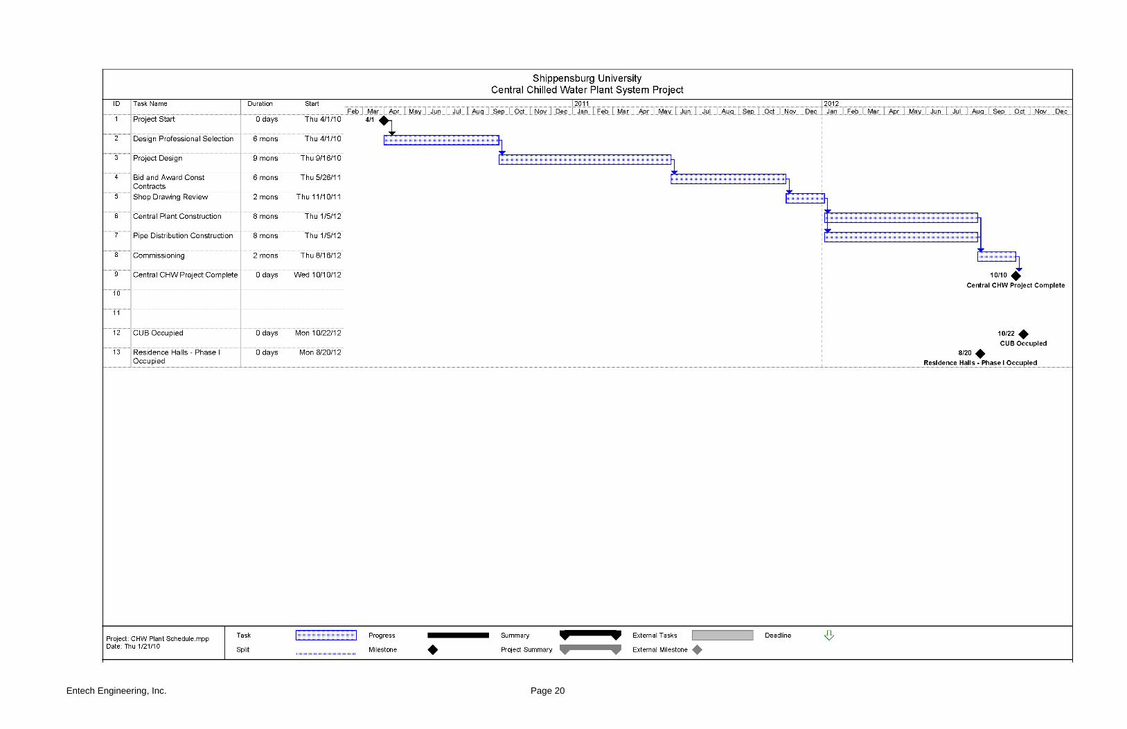
10.0 SCHEDULE AND PHASING
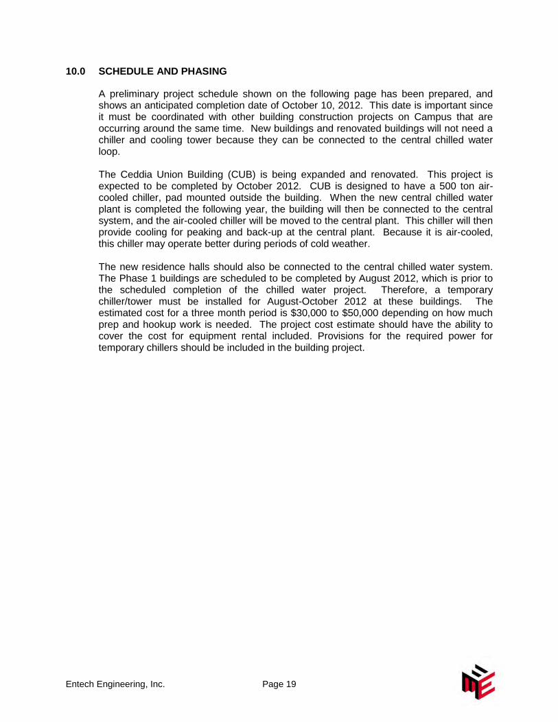
A preliminary project schedule shown on the following page has been prepared, and shows an anticipated completion date of October 10, 2012. This date is important since it must be coordinated with other building construction projects on Campus that are occurring around the same time. New buildings and renovated buildings will not need a chiller and cooling tower because they can be connected to the central chilled water loop. The Ceddia Union Building (CUB) is being expanded and renovated. This project is expected to be completed by October 2012. CUB is designed to have a 500 ton air-cooled chiller, pad mounted outside the building. When the new central chilled water plant is completed the following year, the building will then be connected to the central system, and the air-cooled chiller will be moved to the central plant. This chiller will then provide cooling for peaking and back-up at the central plant. Because it is air-cooled, this chiller may operate better during periods of cold weather. The new residence halls should also be connected to the central chilled water system. The Phase 1 buildings are scheduled to be completed by August 2012, which is prior to the scheduled completion of the chilled water project. Therefore, a temporary chiller/tower must be installed for August-October 2012 at these buildings. The estimated cost for a three month period is $30,000 to $50,000 depending on how much prep and hookup work is needed. The project cost estimate should have the ability to cover the cost for equipment rental included. Provisions for the required power for temporary chillers should be included in the building project.
Entech Engineering, Inc. Page 20
Entech Engineering, Inc. Page 21
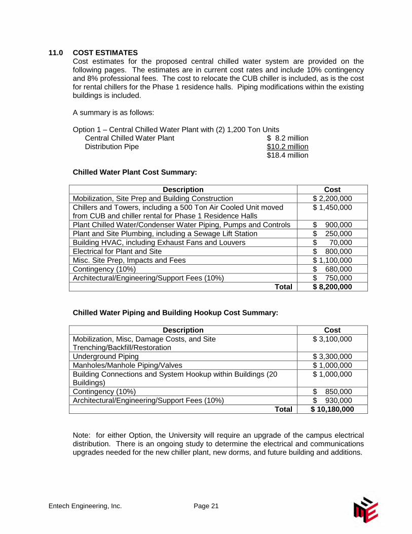
11.0 COST ESTIMATES Cost estimates for the proposed central chilled water system are provided on the following pages. The estimates are in current cost rates and include 10% contingency and 8% professional fees. The cost to relocate the CUB chiller is included, as is the cost for rental chillers for the Phase 1 residence halls. Piping modifications within the existing buildings is included. A summary is as follows: Option 1 – Central Chilled Water Plant with (2) 1,200 Ton Units
Central Chilled Water Plant $ 8.2 million Distribution Pipe $10.2 million
$18.4 million Chilled Water Plant Cost Summary:
Description Cost Mobilization, Site Prep and Building Construction $ 2,200,000 Chillers and Towers, including a 500 Ton Air Cooled Unit moved from CUB and chiller rental for Phase 1 Residence Halls
$ 1,450,000
Plant Chilled Water/Condenser Water Piping, Pumps and Controls $ 900,000 Plant and Site Plumbing, including a Sewage Lift Station $ 250,000 Building HVAC, including Exhaust Fans and Louvers $ 70,000 Electrical for Plant and Site $ 800,000 Misc. Site Prep, Impacts and Fees $ 1,100,000 Contingency (10%) $ 680,000 Architectural/Engineering/Support Fees (10%) $ 750,000 Total $ 8,200,000 Chilled Water Piping and Building Hookup Cost Summary:
Description Cost Mobilization, Misc, Damage Costs, and Site Trenching/Backfill/Restoration
$ 3,100,000
Underground Piping $ 3,300,000 Manholes/Manhole Piping/Valves $ 1,000,000 Building Connections and System Hookup within Buildings (20 Buildings)
$ 1,000,000
Contingency (10%) $ 850,000 Architectural/Engineering/Support Fees (10%) $ 930,000 Total $ 10,180,000 Note: for either Option, the University will require an upgrade of the campus electrical distribution. There is an ongoing study to determine the electrical and communications upgrades needed for the new chiller plant, new dorms, and future building and additions.
Entech Engineering, Inc. Page 22
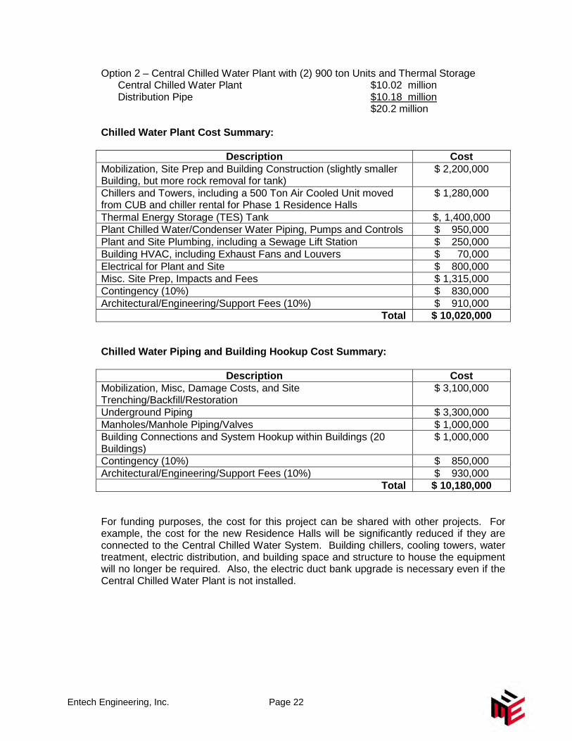
Option 2 – Central Chilled Water Plant with (2) 900 ton Units and Thermal Storage Central Chilled Water Plant $10.02 million Distribution Pipe $10.18 million
$20.2 million Chilled Water Plant Cost Summary:
Description Cost Mobilization, Site Prep and Building Construction (slightly smaller Building, but more rock removal for tank)
$ 2,200,000
Chillers and Towers, including a 500 Ton Air Cooled Unit moved from CUB and chiller rental for Phase 1 Residence Halls
$ 1,280,000
Thermal Energy Storage (TES) Tank $, 1,400,000 Plant Chilled Water/Condenser Water Piping, Pumps and Controls $ 950,000 Plant and Site Plumbing, including a Sewage Lift Station $ 250,000 Building HVAC, including Exhaust Fans and Louvers $ 70,000 Electrical for Plant and Site $ 800,000 Misc. Site Prep, Impacts and Fees $ 1,315,000 Contingency (10%) $ 830,000 Architectural/Engineering/Support Fees (10%) $ 910,000 Total $ 10,020,000 Chilled Water Piping and Building Hookup Cost Summary:
Description Cost Mobilization, Misc, Damage Costs, and Site Trenching/Backfill/Restoration
$ 3,100,000
Underground Piping $ 3,300,000 Manholes/Manhole Piping/Valves $ 1,000,000 Building Connections and System Hookup within Buildings (20 Buildings)
$ 1,000,000
Contingency (10%) $ 850,000 Architectural/Engineering/Support Fees (10%) $ 930,000 Total $ 10,180,000 For funding purposes, the cost for this project can be shared with other projects. For example, the cost for the new Residence Halls will be significantly reduced if they are connected to the Central Chilled Water System. Building chillers, cooling towers, water treatment, electric distribution, and building space and structure to house the equipment will no longer be required. Also, the electric duct bank upgrade is necessary even if the Central Chilled Water Plant is not installed.
Entech Engineering, Inc. Page 23
12.0 CONCLUSION
Because the University is proceeding with a large residence hall building project that requires air conditioning, there is a great opportunity to construct a central chilled water plant for the campus. This type of system will more efficiently provide chilled water for air conditioning to all the campus buildings. The system should be more reliable, easier to maintain than distributed equipment, and remove large equipment from campus buildings. Two options have been presented in this study which should provide flexibility as the campus continues to grow and change. The second option uses thermal storage, a technology which should provide many benefits as the energy market continues to change. The information contained in this report will help guide the University if this project is implemented. Many factors will determine the final design and layout of the system. In the end, the campus should have the infrastructure for providing reliable cooling to the campus for many years.

ATTACHMENT 1
Detailed Cost Estimates
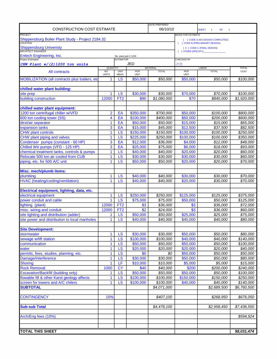
DATE PREPARED
CONSTRUCTION COST ESTIMATE 06/10/10 SHEET 1 OF 1
PROJECT BASIS FOR ESTIMATE
Shippensburg Boiler Plant Study - Project 2184.32 [ ] CODE A (NO DESIGN COMPLETED)LOCATION [ ] CODE B (PRELIMINARY DESIGN)
Shippensburg Univeristy [ X ] CODE C (FINAL DESIGN)ARCHITECT ENGINEER [ ] OTHER (SPECIFY)_________________
Entech Engineering, Inc. file: plant-jed-2-1200Project Estimated: ESTIMATOR CHECKED BY
CHW Plant w/(2)1200 ton units JED JCEQUANTITY MATERIAL LABOR TOTAL
All contracts NO. UNIT PER TOTAL PER TOTAL COSTUNITS MEAS. UNIT UNIT
MOBILIZATION (all contracts plus trailers, etc 1 LS $50,000 $50,000 $50,000 $50,000 $100,000
chilled water plant building:site prep 1 LS $30,000 $30,000 $70,000 $70,000 $100,000building construction 12000 FT2 $90 $1,080,000 $70 $840,000 $1,920,000
chilled water plant equipment:1200 ton centrifugal chiller w/VFD 2 EA $350,000 $700,000 $50,000 $100,000 $800,000600 ton cooling tower (SS) 4 EA $100,000 $400,000 $50,000 $200,000 $600,000dirst/air separator 1 EA $50,000 $50,000 $15,000 $15,000 $65,000expansion tanks 3 EA $15,000 $45,000 $12,500 $37,500 $82,500CHW plant controls 1 LS $150,000 $150,000 $100,000 $100,000 $250,000CHW plant piping and valves 1 LS $225,000 $250,000 $100,000 $100,000 $350,000Condenser pumps (constant - 60 HP) 3 EA $12,000 $36,000 $4,000 $12,000 $48,000Chilled Wtr pumps (VFD - 125 HP) 3 EA $25,000 $75,000 $6,000 $18,000 $93,000chemical treatment tanks, controls & pumps 1 LS $40,000 $40,000 $20,000 $20,000 $60,000Relocate 500 ton air cooled from CUB 1 LS $30,000 $30,000 $30,000 $30,000 $60,000piping, etc. for 500 A/C unit 1 LS $50,000 $50,000 $20,000 $20,000 $70,000
Misc. mech/plumb items:plumbing 1 LS $40,000 $40,000 $30,000 $30,000 $70,000HVAC (heating/cooling/ventilation) 1 LS $40,000 $40,000 $20,000 $30,000 $70,000
Electrical equipment, lighting, data, etc.electrical equipment 1 LS $250,000 $250,000 $125,000 $125,000 $375,000power conduit and cable 1 LS $75,000 $75,000 $50,000 $50,000 $125,000lighting (plant) 12000 FT2 $3 $36,000 $3 $36,000 $72,000misc. wiring and conduit 12000 FT2 $2 $24,000 $3 $36,000 $60,000site lighting and distribution (adder) 1 LS $50,000 $50,000 $25,000 $25,000 $75,000site power and distribution to local manholes 1 LS $40,000 $40,000 $40,000 $40,000 $80,000
Site Development:stormwater 1 LS $30,000 $30,000 $50,000 $50,000 $80,000sewage w/lift station 1 LS $100,000 $100,000 $40,000 $40,000 $140,000communication 1 LS $50,000 $50,000 $50,000 $50,000 $100,000water 1 LS $20,000 $20,000 $20,000 $20,000 $40,000permits, fees, studies, planning, etc. 1 LS $0 $0 $50,000 $50,000 $50,000Damage/interference 1 LS $30,000 $30,000 $50,000 $50,000 $80,000Shoring 1 LF $10,000 $10,000 $5,000 $5,000 $15,000Rock Removal 1000 CY $40 $40,000 $200 $200,000 $240,000Excavation/Backfill (building only) 1 LS $50,000 $50,000 $50,000 $50,000 $100,000flowable fill & other Karst geology affects 1 LS $100,000 $100,000 $150,000 $150,000 $250,000screen for towers and A/C chilers 1 LS $100,000 $100,000 $40,000 $40,000 $140,000SUBTOTAL $4,071,000 $2,689,500 $6,760,500
CONTINGENCY 10% $407,100 $268,950 $676,050
Sub-sub Total $4,478,100 $2,958,450 $7,436,550
Arch/Eng fees (10%) $594,924
TOTAL THIS SHEET $8,031,474
DATE PREPARED
CONSTRUCTION COST ESTIMATE 06/10/10 SHEET 1 OF 1
PROJECT BASIS FOR ESTIMATE
Shippensburg Boiler Plant Study - Project 2184.32 [ ] CODE A (NO DESIGN COMPLETED)LOCATION [ ] CODE B (PRELIMINARY DESIGN)
Shippensburg Univeristy [ X ] CODE C (FINAL DESIGN)ARCHITECT ENGINEER [ ] OTHER (SPECIFY)_________________
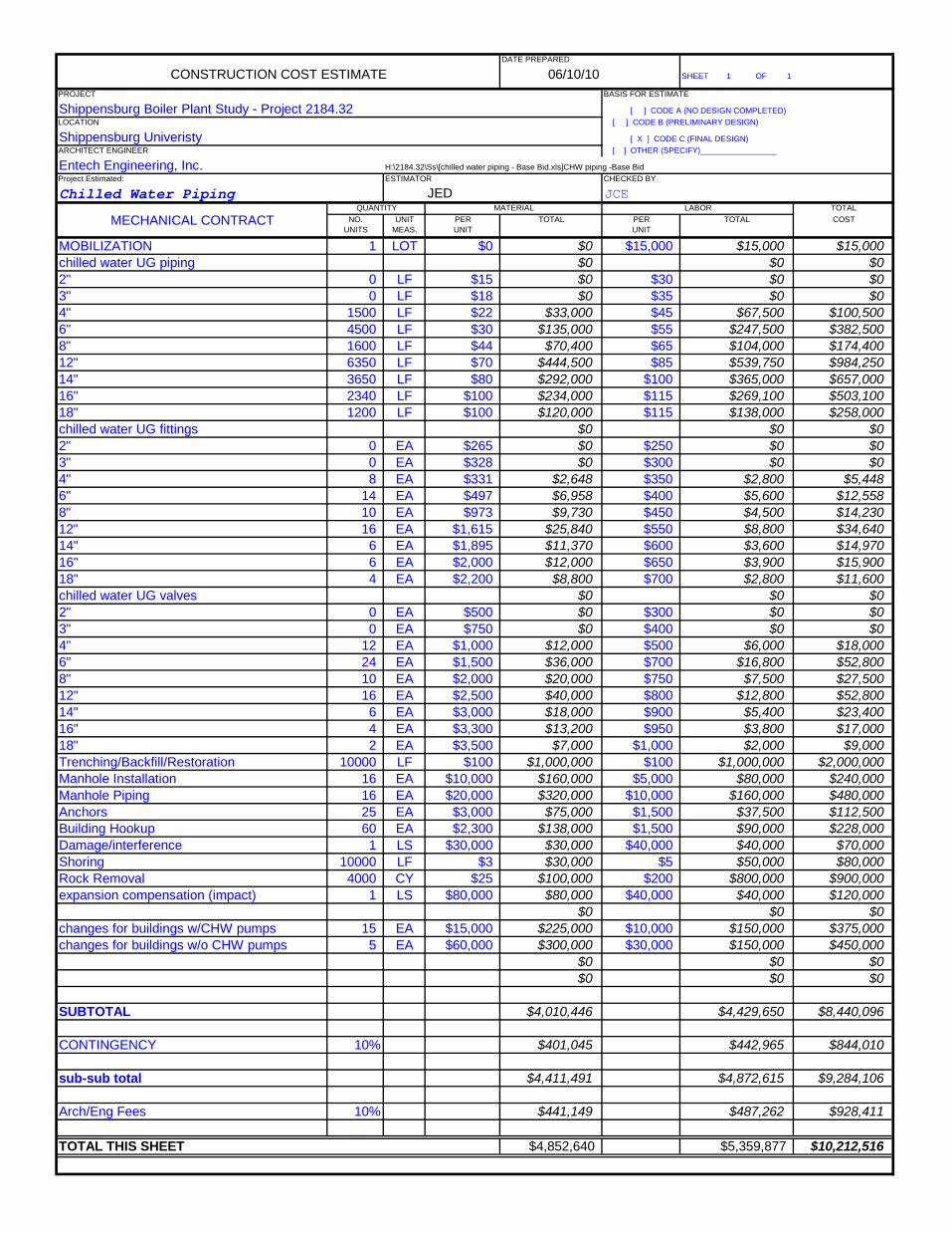
Entech Engineering, Inc. H:\2184.32\Ss\[chilled water piping - Base Bid.xls]CHW piping -Base BidProject Estimated: ESTIMATOR CHECKED BY
Chilled Water Piping JED JCEQUANTITY MATERIAL LABOR TOTAL
MECHANICAL CONTRACT NO. UNIT PER TOTAL PER TOTAL COSTUNITS MEAS. UNIT UNIT
MOBILIZATION 1 LOT $0 $0 $15,000 $15,000 $15,000chilled water UG piping $0 $0 $02" 0 LF $15 $0 $30 $0 $03" 0 LF $18 $0 $35 $0 $04" 1500 LF $22 $33,000 $45 $67,500 $100,5006" 4500 LF $30 $135,000 $55 $247,500 $382,5008" 1600 LF $44 $70,400 $65 $104,000 $174,40012" 6350 LF $70 $444,500 $85 $539,750 $984,25014" 3650 LF $80 $292,000 $100 $365,000 $657,00016" 2340 LF $100 $234,000 $115 $269,100 $503,10018" 1200 LF $100 $120,000 $115 $138,000 $258,000chilled water UG fittings $0 $0 $02" 0 EA $265 $0 $250 $0 $03" 0 EA $328 $0 $300 $0 $04" 8 EA $331 $2,648 $350 $2,800 $5,4486" 14 EA $497 $6,958 $400 $5,600 $12,5588" 10 EA $973 $9,730 $450 $4,500 $14,23012" 16 EA $1,615 $25,840 $550 $8,800 $34,64014" 6 EA $1,895 $11,370 $600 $3,600 $14,97016" 6 EA $2,000 $12,000 $650 $3,900 $15,90018" 4 EA $2,200 $8,800 $700 $2,800 $11,600chilled water UG valves $0 $0 $02" 0 EA $500 $0 $300 $0 $03" 0 EA $750 $0 $400 $0 $04" 12 EA $1,000 $12,000 $500 $6,000 $18,0006" 24 EA $1,500 $36,000 $700 $16,800 $52,8008" 10 EA $2,000 $20,000 $750 $7,500 $27,50012" 16 EA $2,500 $40,000 $800 $12,800 $52,80014" 6 EA $3,000 $18,000 $900 $5,400 $23,40016" 4 EA $3,300 $13,200 $950 $3,800 $17,00018" 2 EA $3,500 $7,000 $1,000 $2,000 $9,000Trenching/Backfill/Restoration 10000 LF $100 $1,000,000 $100 $1,000,000 $2,000,000Manhole Installation 16 EA $10,000 $160,000 $5,000 $80,000 $240,000Manhole Piping 16 EA $20,000 $320,000 $10,000 $160,000 $480,000Anchors 25 EA $3,000 $75,000 $1,500 $37,500 $112,500Building Hookup 60 EA $2,300 $138,000 $1,500 $90,000 $228,000Damage/interference 1 LS $30,000 $30,000 $40,000 $40,000 $70,000Shoring 10000 LF $3 $30,000 $5 $50,000 $80,000Rock Removal 4000 CY $25 $100,000 $200 $800,000 $900,000expansion compensation (impact) 1 LS $80,000 $80,000 $40,000 $40,000 $120,000
$0 $0 $0changes for buildings w/CHW pumps 15 EA $15,000 $225,000 $10,000 $150,000 $375,000changes for buildings w/o CHW pumps 5 EA $60,000 $300,000 $30,000 $150,000 $450,000
$0 $0 $0$0 $0 $0
SUBTOTAL $4,010,446 $4,429,650 $8,440,096
CONTINGENCY 10% $401,045 $442,965 $844,010
sub-sub total $4,411,491 $4,872,615 $9,284,106
Arch/Eng Fees 10% $441,149 $487,262 $928,411
TOTAL THIS SHEET $4,852,640 $5,359,877 $10,212,516
DATE PREPARED
CONSTRUCTION COST ESTIMATE 06/10/10 SHEET 1 OF 1
PROJECT BASIS FOR ESTIMATE
Shippensburg Boiler Plant Study - Project 2184.32 [ ] CODE A (NO DESIGN COMPLETED)LOCATION [ ] CODE B (PRELIMINARY DESIGN)
Shippensburg Univeristy [ X ] CODE C (FINAL DESIGN)ARCHITECT ENGINEER [ ] OTHER (SPECIFY)_________________
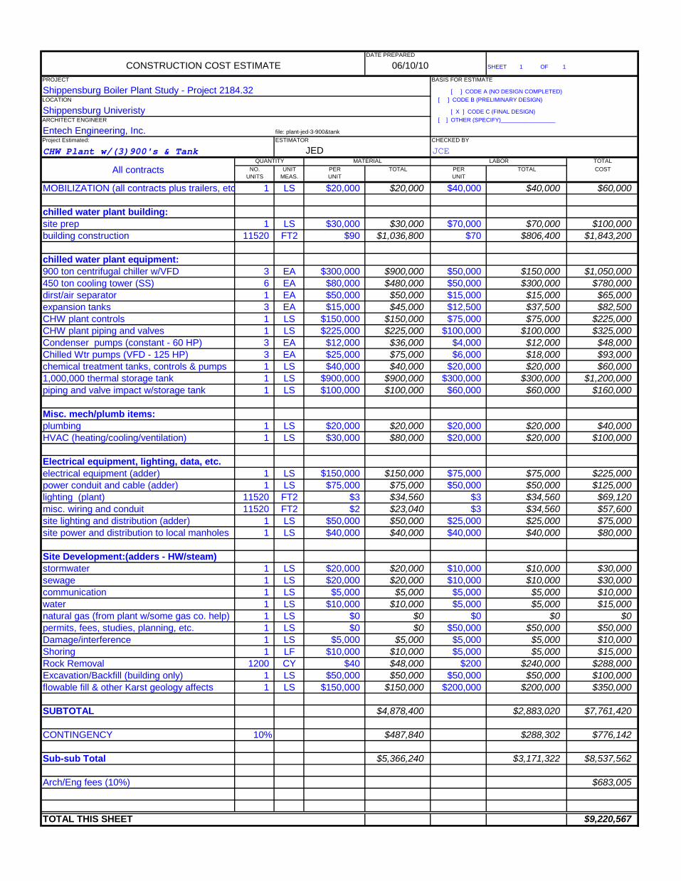
Entech Engineering, Inc. file: plant-jed-3-900&tankProject Estimated: ESTIMATOR CHECKED BY
CHW Plant w/(3)900's & Tank JED JCEQUANTITY MATERIAL LABOR TOTAL
All contracts NO. UNIT PER TOTAL PER TOTAL COSTUNITS MEAS. UNIT UNIT
MOBILIZATION (all contracts plus trailers, etc 1 LS $20,000 $20,000 $40,000 $40,000 $60,000
chilled water plant building:site prep 1 LS $30,000 $30,000 $70,000 $70,000 $100,000building construction 11520 FT2 $90 $1,036,800 $70 $806,400 $1,843,200
chilled water plant equipment:900 ton centrifugal chiller w/VFD 3 EA $300,000 $900,000 $50,000 $150,000 $1,050,000450 ton cooling tower (SS) 6 EA $80,000 $480,000 $50,000 $300,000 $780,000dirst/air separator 1 EA $50,000 $50,000 $15,000 $15,000 $65,000expansion tanks 3 EA $15,000 $45,000 $12,500 $37,500 $82,500CHW plant controls 1 LS $150,000 $150,000 $75,000 $75,000 $225,000CHW plant piping and valves 1 LS $225,000 $225,000 $100,000 $100,000 $325,000Condenser pumps (constant - 60 HP) 3 EA $12,000 $36,000 $4,000 $12,000 $48,000Chilled Wtr pumps (VFD - 125 HP) 3 EA $25,000 $75,000 $6,000 $18,000 $93,000chemical treatment tanks, controls & pumps 1 LS $40,000 $40,000 $20,000 $20,000 $60,0001,000,000 thermal storage tank 1 LS $900,000 $900,000 $300,000 $300,000 $1,200,000piping and valve impact w/storage tank 1 LS $100,000 $100,000 $60,000 $60,000 $160,000
Misc. mech/plumb items:plumbing 1 LS $20,000 $20,000 $20,000 $20,000 $40,000HVAC (heating/cooling/ventilation) 1 LS $30,000 $80,000 $20,000 $20,000 $100,000
Electrical equipment, lighting, data, etc.electrical equipment (adder) 1 LS $150,000 $150,000 $75,000 $75,000 $225,000power conduit and cable (adder) 1 LS $75,000 $75,000 $50,000 $50,000 $125,000lighting (plant) 11520 FT2 $3 $34,560 $3 $34,560 $69,120misc. wiring and conduit 11520 FT2 $2 $23,040 $3 $34,560 $57,600site lighting and distribution (adder) 1 LS $50,000 $50,000 $25,000 $25,000 $75,000site power and distribution to local manholes 1 LS $40,000 $40,000 $40,000 $40,000 $80,000
Site Development:(adders - HW/steam)stormwater 1 LS $20,000 $20,000 $10,000 $10,000 $30,000sewage 1 LS $20,000 $20,000 $10,000 $10,000 $30,000communication 1 LS $5,000 $5,000 $5,000 $5,000 $10,000water 1 LS $10,000 $10,000 $5,000 $5,000 $15,000natural gas (from plant w/some gas co. help) 1 LS $0 $0 $0 $0 $0permits, fees, studies, planning, etc. 1 LS $0 $0 $50,000 $50,000 $50,000Damage/interference 1 LS $5,000 $5,000 $5,000 $5,000 $10,000Shoring 1 LF $10,000 $10,000 $5,000 $5,000 $15,000Rock Removal 1200 CY $40 $48,000 $200 $240,000 $288,000Excavation/Backfill (building only) 1 LS $50,000 $50,000 $50,000 $50,000 $100,000flowable fill & other Karst geology affects 1 LS $150,000 $150,000 $200,000 $200,000 $350,000
SUBTOTAL $4,878,400 $2,883,020 $7,761,420
CONTINGENCY 10% $487,840 $288,302 $776,142
Sub-sub Total $5,366,240 $3,171,322 $8,537,562
Arch/Eng fees (10%) $683,005
TOTAL THIS SHEET $9,220,567


