
Seismic Modeling, Migration and VelocityInversion
Full Waveform Inversion
Bee Bednar
Panorama Technologies, Inc.14811 St Marys Lane, Suite 150
Houston TX 77079
May 30, 2014
Bee Bednar (Panorama Technologies) Seismic Modeling, Migration and Velocity Inversion May 30, 2014 1 / 53

Outline
1 Prestack Inversion
2 Full Waveform InversionThe Basic Idea
3 The Math
4 Marmousi ExampleEstimating the Initial ModelFWI
Bee Bednar (Panorama Technologies) Seismic Modeling, Migration and Velocity Inversion May 30, 2014 2 / 53

Prestack Inversion
Outline
1 Prestack Inversion
2 Full Waveform InversionThe Basic Idea
3 The Math
4 Marmousi ExampleEstimating the Initial ModelFWI
Bee Bednar (Panorama Technologies) Seismic Modeling, Migration and Velocity Inversion May 30, 2014 3 / 53

Prestack Inversion
AVA Based ”Inversion”
Prestack inversion is sometimes based on minimizing
F (IP , IS, ρ) = α∑i,j
[Sdata
ij − Sij (IP , IS, ρ)]2
+∑
ij
‖ Rij (IP , IS, ρ) ‖
+∑
j
[‖ I low
P − I lowP ‖ + ‖ I low
S − I lowS ‖ + ‖ ρlow − ρlow ‖
]subject to
IPmin ≤ IP ≤ IPmax
ISmin ≤ IS ≤ ISmax
ρmin ≤ ρ ≤ ρmax (1)
Bee Bednar (Panorama Technologies) Seismic Modeling, Migration and Velocity Inversion May 30, 2014 4 / 53

Prestack Inversion
AVA Based ”Inversion”
Notes:IP , IS, are P and S impedance and ρ is density in timei is the angle-stack indexj is the sample indexRij (IP , IS, ρ) is the angle-dependent PP reflectivitySdata
ij is the measured AVA amplitude
Sij (IP , IS, ρ) is the 1D numerically simulated synthetic seismic dataVariables with low superscripts designate low-frequency components ofP-impedance, S-impedance, and density respectively.
Bee Bednar (Panorama Technologies) Seismic Modeling, Migration and Velocity Inversion May 30, 2014 5 / 53

Prestack Inversion
AVA Based ”Inversion”
This is not Full Waveform Inversion
Bee Bednar (Panorama Technologies) Seismic Modeling, Migration and Velocity Inversion May 30, 2014 6 / 53

Full Waveform Inversion
Outline
1 Prestack Inversion
2 Full Waveform InversionThe Basic Idea
3 The Math
4 Marmousi ExampleEstimating the Initial ModelFWI
Bee Bednar (Panorama Technologies) Seismic Modeling, Migration and Velocity Inversion May 30, 2014 7 / 53

Full Waveform Inversion The Basic Idea
Full Waveform Inversion
For a given modelFor each observed shot, synthesize data to match the real acquisition
Use a full two-way modeling algorithmSave a trace at each model node
Compute the difference between the shot and the real dataThese data are called the residuals
Back propagated the residuals into the modelUse a full two-way modeling algorithmSave a trace at each model node
Preform a shot-profile migration of the residualsThe shot is the forward-propagated syntheticThe receiver traces are the back-propagated residualsDivide the back by the forward propagated traces
Normalize the image above by the velocity squaredAdd the normalized image to the current modelRepeat the previous steps until the norm of the model difference is small
FWI is really a iterative migration scheme
Bee Bednar (Panorama Technologies) Seismic Modeling, Migration and Velocity Inversion May 30, 2014 8 / 53

The Math
Outline
1 Prestack Inversion
2 Full Waveform InversionThe Basic Idea
3 The Math
4 Marmousi ExampleEstimating the Initial ModelFWI
Bee Bednar (Panorama Technologies) Seismic Modeling, Migration and Velocity Inversion May 30, 2014 9 / 53
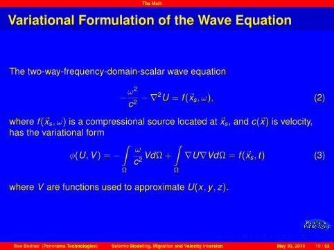
The Math
Variational Formulation of the Wave Equation
The two-way-frequency-domain-scalar wave equation
−ω2
c2 −∇2U = f (~xs, ω), (2)
where f (~xs, ω) is a compressional source located at ~xs, and c(~x) is velocity,has the variational form
φ(U,V ) = −∫Ω
ω
c2 VdΩ +
∫Ω
∇U∇VdΩ = f (~xs, t) (3)
where V are functions used to approximate U(x , y , z).
Bee Bednar (Panorama Technologies) Seismic Modeling, Migration and Velocity Inversion May 30, 2014 10 / 53

The Math
The Matrix Form
Given a family, Vk , of approximating functions s we can approximate U, and f
by u(~x) =n∑
k=1Uk Vk (~x) and f (~xs, ω) =
n∑k=1
fk Vk (~x) so that the variational form
in equation (3)n∑
k=1
Ukφ(Vk ,Vj ) =n∑
k=1
fk∫Ω
Vk VjdΩ (4)
can be expressed in matrix form as
S~U = M~f (5)
Here S is called the complex impedance matrix and M the stiffness matrix.
Bee Bednar (Panorama Technologies) Seismic Modeling, Migration and Velocity Inversion May 30, 2014 11 / 53

The Math
Notes
S~U = M~f is a single frequency equation.The matrix M does not depend on Uk . Its more like a new source term.With proper choice of Vk we can arrange for M = I.For our purposes here and to simplify notation,
S~U = ~f (6)
We assume that S is square, symmetric, and invertible.The inverse, S−1, of S is a modeling ”operator”Thus
~U = S−1~f (7)
Bee Bednar (Panorama Technologies) Seismic Modeling, Migration and Velocity Inversion May 30, 2014 12 / 53

The Math
Full Waveform Inversion
Full waveform inversion begins with a suitably chosen objective function whichfor the classical case is
E =‖ J(~D, ~U) ‖=‖ ~D − ~U ‖ . (8)
where ‖ · ‖ is the usual least squares norm, ~D is the observed seismic dataand ~U = S−1~f is synthetic data corresponding to the current velocity modelestimate.
Bee Bednar (Panorama Technologies) Seismic Modeling, Migration and Velocity Inversion May 30, 2014 13 / 53

The Math
The Inversion Scheme
Given an initial velocity model, we can consider two update schemes:Move in the negative direction of the gradient of E .Use the full Newton method (Lines and Treitel 1984) to update the currentmodel.
Choosing the second means that our updating scheme immediately takes theform
~c n = ~c n−1 − H−1∇~c n−1E (9)
Thus, we must calculated the gradient of E and also invert the Hessian matrixH.
Bee Bednar (Panorama Technologies) Seismic Modeling, Migration and Velocity Inversion May 30, 2014 14 / 53

The Math
The Inversion Scheme cont’d
Finding the gradient of the objective function E requires that we find thegradient of ~U = S−1~f with respect to the sampled velocity model ck Thus,
∂S∂ck
~U + S∂~U∂ck
= 0 (10)
∂~U∂ck
= S−1~Pk (11)
and~Pk = − ∂S
∂ck
~U (12)
where the middle equation defines what is normally called the partialderivative wave field, and the bottom equation defines the so called virtualsource vector required to perturb k -th velocity element.
Bee Bednar (Panorama Technologies) Seismic Modeling, Migration and Velocity Inversion May 30, 2014 15 / 53

The Math
The Inversion Scheme cont’d
From the objective function
∂E∂ck
= Re
8>>>>>>>>>>>><>>>>>>>>>>>>:
»∂U1
∂ck
∂U2
∂ck· · · ∂Unr
∂ck· · · ∂Unn
∂ck
–26666666666664
(U1 − D1)(U2 − D2)
...(Unr − Dnr )
0...0
37777777777775
9>>>>>>>>>>>>=>>>>>>>>>>>>;(13)
and from the partial derivative wave field
∂E∂ck
= Ren
(~Pk )T S−1~r
o(14)
where~r =
h(U1 − D1), (U2 − D2), · · · (Unr − Dnr ), 0, · · · , 0
iT(15)
Bee Bednar (Panorama Technologies) Seismic Modeling, Migration and Velocity Inversion May 30, 2014 16 / 53

The Math
The Inversion Scheme cont’d
Finally, we approximate the Hessian via ~Pk so that for each k, the updatingscheme is
c l+1k = c l
k + α∑ω
Re
(~Pk )T S−1~r
Re
(~Pk )T ~Pk + λ
(16)
Bee Bednar (Panorama Technologies) Seismic Modeling, Migration and Velocity Inversion May 30, 2014 17 / 53
Marmousi Example
Outline
1 Prestack Inversion
2 Full Waveform InversionThe Basic Idea
3 The Math
4 Marmousi ExampleEstimating the Initial ModelFWI
Bee Bednar (Panorama Technologies) Seismic Modeling, Migration and Velocity Inversion May 30, 2014 18 / 53

Marmousi Example Estimating the Initial Model
Marmousi MVA
(a) Gather Picks (b) Semblance Picks (c) NMO’d Gather
Typical Marmousi gather with picks, a semblance panel with picks, and theNMO corrected gather.
Bee Bednar (Panorama Technologies) Seismic Modeling, Migration and Velocity Inversion May 30, 2014 19 / 53

Marmousi Example Estimating the Initial Model
Marmousi MVA
(d) Marmousi Time-RMS model (e) Marmousi Depth-Interval model
Initial stacking velocity models in time-RMS (left) and interval-depth (right).
Bee Bednar (Panorama Technologies) Seismic Modeling, Migration and Velocity Inversion May 30, 2014 20 / 53

Marmousi Example Estimating the Initial Model
Marmousi MVA
First iteration Marmousi stacking velocity based Kirchhoff migration.
Bee Bednar (Panorama Technologies) Seismic Modeling, Migration and Velocity Inversion May 30, 2014 21 / 53

Marmousi Example Estimating the Initial Model
Marmousi MVA
(f) Marmousi Time-RMS model (g) Marmousi Depth-Interval model
Second Kirchhoff based MVA models in time-RMS (left) and interval-depth(right).
Bee Bednar (Panorama Technologies) Seismic Modeling, Migration and Velocity Inversion May 30, 2014 22 / 53

Marmousi Example Estimating the Initial Model
Marmousi MVA
Second iteration Marmousi Kirchhoff based MVA Kirchhoff migration.
Bee Bednar (Panorama Technologies) Seismic Modeling, Migration and Velocity Inversion May 30, 2014 23 / 53

Marmousi Example Estimating the Initial Model
Marmousi MVA
(h) Marmousi Time-RMS model (i) Marmousi Depth-Interval model
Second Kirchhoff based MVA models in time-RMS (left) and interval-depth(right).
Bee Bednar (Panorama Technologies) Seismic Modeling, Migration and Velocity Inversion May 30, 2014 24 / 53

Marmousi Example Estimating the Initial Model
Marmousi MVA
Third iteration Kirchhoff based MVA Kirchhoff migration.
Bee Bednar (Panorama Technologies) Seismic Modeling, Migration and Velocity Inversion May 30, 2014 25 / 53

Marmousi Example Estimating the Initial Model
Marmousi MVA
Fourth iteration Kirchhoff MVA based velocity model.
Bee Bednar (Panorama Technologies) Seismic Modeling, Migration and Velocity Inversion May 30, 2014 26 / 53

Marmousi Example Estimating the Initial Model
Marmousi MVA
Fourth iteration Kirchhoff MVA based Kirchhoff migration.
Bee Bednar (Panorama Technologies) Seismic Modeling, Migration and Velocity Inversion May 30, 2014 27 / 53

Marmousi Example Estimating the Initial Model
Marmousi MVA
Bottom horizon for constant velocity analysis.
Bee Bednar (Panorama Technologies) Seismic Modeling, Migration and Velocity Inversion May 30, 2014 28 / 53

Marmousi Example Estimating the Initial Model
Marmousi MVA
Fourth iteration Kirchhoff MVA based model with bottom horizon 4000meter/second velocity flood.
Bee Bednar (Panorama Technologies) Seismic Modeling, Migration and Velocity Inversion May 30, 2014 29 / 53

Marmousi Example Estimating the Initial Model
Marmousi MVA
Fourth iteration Kirchhoff MVA based model with bottom horizon 4000meter/second velocity flood migration.
Bee Bednar (Panorama Technologies) Seismic Modeling, Migration and Velocity Inversion May 30, 2014 30 / 53

Marmousi Example Estimating the Initial Model
Marmousi MVA
Fourth iteration Kirchhoff MVA based model with bottom horizon 5000meter/second velocity flood migration.
Bee Bednar (Panorama Technologies) Seismic Modeling, Migration and Velocity Inversion May 30, 2014 31 / 53

Marmousi Example Estimating the Initial Model
Marmousi MVA
The true Marmousi model.
Bee Bednar (Panorama Technologies) Seismic Modeling, Migration and Velocity Inversion May 30, 2014 32 / 53
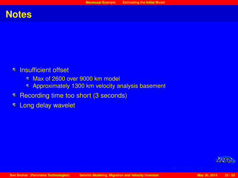
Marmousi Example Estimating the Initial Model
Notes
Insufficient offsetMax of 2600 over 9000 km modelApproximately 1300 km velocity analysis basement
Recording time too short (3 seconds)Long delay wavelet
Bee Bednar (Panorama Technologies) Seismic Modeling, Migration and Velocity Inversion May 30, 2014 33 / 53

Marmousi Example FWI
Marmousi Inversion
Estimated Marmousi velocity model from the iterative Migration VelocityAnalysis above.
Bee Bednar (Panorama Technologies) Seismic Modeling, Migration and Velocity Inversion May 30, 2014 34 / 53

Marmousi Example FWI
Marmousi MVA
Kirchhoff migration using fourth iteration MVA.
Bee Bednar (Panorama Technologies) Seismic Modeling, Migration and Velocity Inversion May 30, 2014 35 / 53

Marmousi Example FWI
Marmousi Inversion
Estimated Marmousi velocity model. This model was obtained throughiterative Migration Velocity Analysis.
Bee Bednar (Panorama Technologies) Seismic Modeling, Migration and Velocity Inversion May 30, 2014 36 / 53

Marmousi Example FWI
Marmousi Inversion
Estimated Marmousi velocity model after 6 iterations
Bee Bednar (Panorama Technologies) Seismic Modeling, Migration and Velocity Inversion May 30, 2014 37 / 53

Marmousi Example FWI
Marmousi Inversion
Estimated Marmousi velocity model after 12 iterations
Bee Bednar (Panorama Technologies) Seismic Modeling, Migration and Velocity Inversion May 30, 2014 38 / 53

Marmousi Example FWI
Marmousi Inversion
Estimated Marmousi velocity model after 18 iterations
Bee Bednar (Panorama Technologies) Seismic Modeling, Migration and Velocity Inversion May 30, 2014 39 / 53

Marmousi Example FWI
Marmousi Inversion
Estimated Marmousi velocity model after 24 iterations
Bee Bednar (Panorama Technologies) Seismic Modeling, Migration and Velocity Inversion May 30, 2014 40 / 53

Marmousi Example FWI
Marmousi Inversion
Estimated Marmousi velocity model after 30 iterations
Bee Bednar (Panorama Technologies) Seismic Modeling, Migration and Velocity Inversion May 30, 2014 41 / 53

Marmousi Example FWI
Marmousi Inversion
Estimated Marmousi velocity model after 42 iterations
Bee Bednar (Panorama Technologies) Seismic Modeling, Migration and Velocity Inversion May 30, 2014 42 / 53

Marmousi Example FWI
Marmousi Inversion
Estimated Marmousi velocity model after 48 iterations
Bee Bednar (Panorama Technologies) Seismic Modeling, Migration and Velocity Inversion May 30, 2014 43 / 53

Marmousi Example FWI
Marmousi Inversion
Estimated Marmousi velocity model after 54 iterations
Bee Bednar (Panorama Technologies) Seismic Modeling, Migration and Velocity Inversion May 30, 2014 44 / 53

Marmousi Example FWI
Marmousi Inversion
Estimated Marmousi velocity model after 60 iterations
Bee Bednar (Panorama Technologies) Seismic Modeling, Migration and Velocity Inversion May 30, 2014 45 / 53

Marmousi Example FWI
Marmousi Inversion
True Marmousi model.
Bee Bednar (Panorama Technologies) Seismic Modeling, Migration and Velocity Inversion May 30, 2014 46 / 53

Marmousi Example FWI
Marmousi Inversion
(j) After 100 iterations (k) After 600+ iterations
(l) Velocity error (600+ iterations) (m) The RMS error
Marmousi Full Waveform InversionBee Bednar (Panorama Technologies) Seismic Modeling, Migration and Velocity Inversion May 30, 2014 47 / 53

Marmousi Example FWI
Marmousi Inversion
Log extraction locations.
Bee Bednar (Panorama Technologies) Seismic Modeling, Migration and Velocity Inversion May 30, 2014 48 / 53

Marmousi Example FWI
Marmousi Inversion
Inverted Versus True Logs at the locations specified in the previous slide.
Bee Bednar (Panorama Technologies) Seismic Modeling, Migration and Velocity Inversion May 30, 2014 49 / 53

Marmousi Example FWI
Process Review
The true modelNine km by three km (depth)
The observed dataNine km offsetBroadband wavelet from .3 HZ to 50 HZ
Low frequency and long offsets are the key
Five second recording timeModel grid was 16m X 16m
Bee Bednar (Panorama Technologies) Seismic Modeling, Migration and Velocity Inversion May 30, 2014 50 / 53

Marmousi Example FWI
The observed data
Marmousi Synthetic Data
Bee Bednar (Panorama Technologies) Seismic Modeling, Migration and Velocity Inversion May 30, 2014 51 / 53

Marmousi Example FWI
The inversion process
We started with a MVA modelVirtually no reflectionsReasonably accurate shallowFirst iteration essentially muted the first breaksFirst iteration is exactly equivalent to migrating with our initial model
Lailly: Migration is the first step in inversion
We calculated a new velocity model from residuals and a synthetic shotWe shot a new synthetic data setWe imaged the residualsWe repeated the exercise until model differences became negligibleIn this case the model is as good as can be expected
This kind of inversion is theoretically valid for all Earth Models.
Bee Bednar (Panorama Technologies) Seismic Modeling, Migration and Velocity Inversion May 30, 2014 52 / 53

Marmousi Example FWI
Questions?
Bee Bednar (Panorama Technologies) Seismic Modeling, Migration and Velocity Inversion May 30, 2014 53 / 53


