1© KEMET Electronics Corporation • P.O. Box 5928 • Greenville, SC 29606 • 864-963-6300 • www.kemet.com A4031_ALS30_31 • 3/24/2017One world. One KEMET
Benefits
• Compact size• Long life, up to 20,000 hours at +85°C (VR, IR applied)• High ripple current• Excellent surge voltage capability• Optimized designs available upon request
Overview
KEMET's ALS30/31 Series of screw terminal capacitors covers a wide range of case sizes and voltage ratings featuring high ripple currents and long-life performance. They are ideally suited for industrial and commercial applications demanding high reliability and long-life expectancy such as frequency converters, uninterruptible power supply (UPS) systems and switch mode power supplies (SMPS).
Applications
Typical applications for KEMET's ALS30/31 Series of capacitors include smoothing, energy storage or pulse operation in telecommunication demanding power supplies, process control, AC motor control, traction, welding, and measuring.
Screw Terminal Aluminum Electrolytic Capacitors
ALS30/31 Series, +85°C
Part Number System
ALS3 0 A 153 DA 025
Series Stud Option TerminationCapacitance Code
(µF)Size Code Rated Voltage (VDC)
Screw Terminal Aluminum
Electrolytic
0 = Plain Can 1 = Threaded mounting stud
See Termination Table
First two digits represent significant
figures. Third digit specifies number
of zeros.
See Dimension Table
025 = 25 040 = 40 063 = 63 100 = 100 200 = 200 250 = 250
350 = 350 400 = 400 415 = 415 450 = 450 500 = 500
2© KEMET Electronics Corporation • P.O. Box 5928 • Greenville, SC 29606 • 864-963-6300 • www.kemet.com A4031_ALS30_31 • 3/24/2017
Screw Terminal Aluminum Electrolytic Capacitors – ALS30/31 Series, +85°C
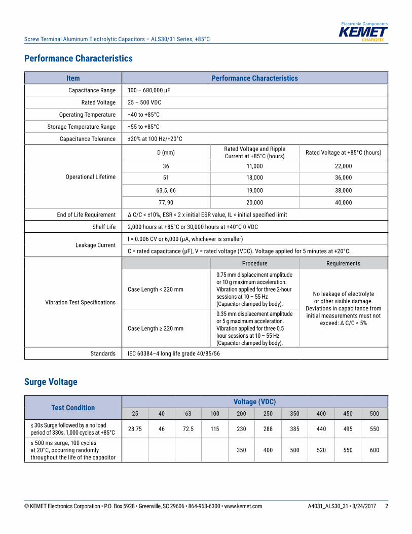
Performance Characteristics
Item Performance CharacteristicsCapacitance Range 100 – 680,000 µF
Rated Voltage 25 – 500 VDC
Operating Temperature −40 to +85°C
Storage Temperature Range −55 to +85°C
Capacitance Tolerance ±20% at 100 Hz/+20°C
Operational Lifetime
D (mm) Rated Voltage and Ripple Current at +85°C (hours) Rated Voltage at +85°C (hours)
36 11,000 22,000
51 18,000 36,000
63.5, 66 19,000 38,000
77, 90 20,000 40,000
End of Life Requirement ∆ C/C < ±10%, ESR < 2 x initial ESR value, IL < initial specified limit
Shelf Life 2,000 hours at +85°C or 30,000 hours at +40°C 0 VDC
Leakage CurrentI = 0.006 CV or 6,000 (µA, whichever is smaller)
C = rated capacitance (µF), V = rated voltage (VDC). Voltage applied for 5 minutes at +20°C.
Vibration Test Specifications
Procedure Requirements
Case Length < 220 mm
0.75 mm displacement amplitude or 10 g maximum acceleration.Vibration applied for three 2-hour sessions at 10 – 55 Hz(Capacitor clamped by body).
No leakage of electrolyte or other visible damage.
Deviations in capacitance from initial measurements must not
exceed: ∆ C/C < 5%Case Length ≥ 220 mm
0.35 mm displacement amplitude or 5 g maximum acceleration.Vibration applied for three 0.5 hour sessions at 10 – 55 Hz(Capacitor clamped by body).
Standards IEC 60384–4 long life grade 40/85/56
Surge Voltage
Test ConditionVoltage (VDC)
25 40 63 100 200 250 350 400 450 500
≤ 30s Surge followed by a no load period of 330s, 1,000 cycles at +85°C 28.75 46 72.5 115 230 288 385 440 495 550
≤ 500 ms surge, 100 cycles at 20°C, occurring randomly throughout the life of the capacitor
350 400 500 520 550 600
3© KEMET Electronics Corporation • P.O. Box 5928 • Greenville, SC 29606 • 864-963-6300 • www.kemet.com A4031_ALS30_31 • 3/24/2017
Screw Terminal Aluminum Electrolytic Capacitors – ALS30/31 Series, +85°C
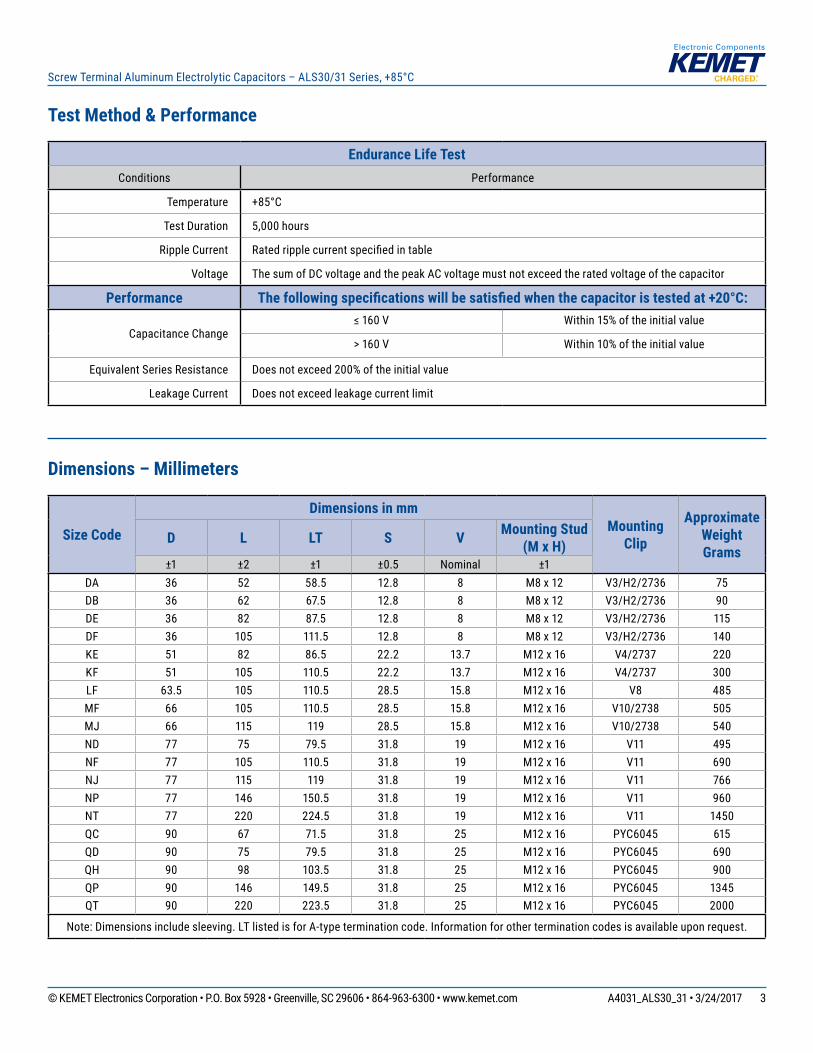
Test Method & Performance
Endurance Life TestConditions Performance
Temperature +85°C
Test Duration 5,000 hours
Ripple Current Rated ripple current specified in table
Voltage The sum of DC voltage and the peak AC voltage must not exceed the rated voltage of the capacitor
Performance The following specifications will be satisfied when the capacitor is tested at +20°C:
Capacitance Change≤ 160 V Within 15% of the initial value
> 160 V Within 10% of the initial value
Equivalent Series Resistance Does not exceed 200% of the initial value
Leakage Current Does not exceed leakage current limit
Dimensions – Millimeters
Size Code
Dimensions in mmMounting
Clip
Approximate Weight Grams
D L LT S V Mounting Stud (M x H)
±1 ±2 ±1 ±0.5 Nominal ±1DA 36 52 58.5 12.8 8 M8 x 12 V3/H2/2736 75DB 36 62 67.5 12.8 8 M8 x 12 V3/H2/2736 90DE 36 82 87.5 12.8 8 M8 x 12 V3/H2/2736 115DF 36 105 111.5 12.8 8 M8 x 12 V3/H2/2736 140KE 51 82 86.5 22.2 13.7 M12 x 16 V4/2737 220KF 51 105 110.5 22.2 13.7 M12 x 16 V4/2737 300LF 63.5 105 110.5 28.5 15.8 M12 x 16 V8 485MF 66 105 110.5 28.5 15.8 M12 x 16 V10/2738 505MJ 66 115 119 28.5 15.8 M12 x 16 V10/2738 540ND 77 75 79.5 31.8 19 M12 x 16 V11 495NF 77 105 110.5 31.8 19 M12 x 16 V11 690NJ 77 115 119 31.8 19 M12 x 16 V11 766NP 77 146 150.5 31.8 19 M12 x 16 V11 960NT 77 220 224.5 31.8 19 M12 x 16 V11 1450QC 90 67 71.5 31.8 25 M12 x 16 PYC6045 615QD 90 75 79.5 31.8 25 M12 x 16 PYC6045 690QH 90 98 103.5 31.8 25 M12 x 16 PYC6045 900QP 90 146 149.5 31.8 25 M12 x 16 PYC6045 1345QT 90 220 223.5 31.8 25 M12 x 16 PYC6045 2000
Note: Dimensions include sleeving. LT listed is for A-type termination code. Information for other termination codes is available upon request.
4© KEMET Electronics Corporation • P.O. Box 5928 • Greenville, SC 29606 • 864-963-6300 • www.kemet.com A4031_ALS30_31 • 3/24/2017
Screw Terminal Aluminum Electrolytic Capacitors – ALS30/31 Series, +85°C
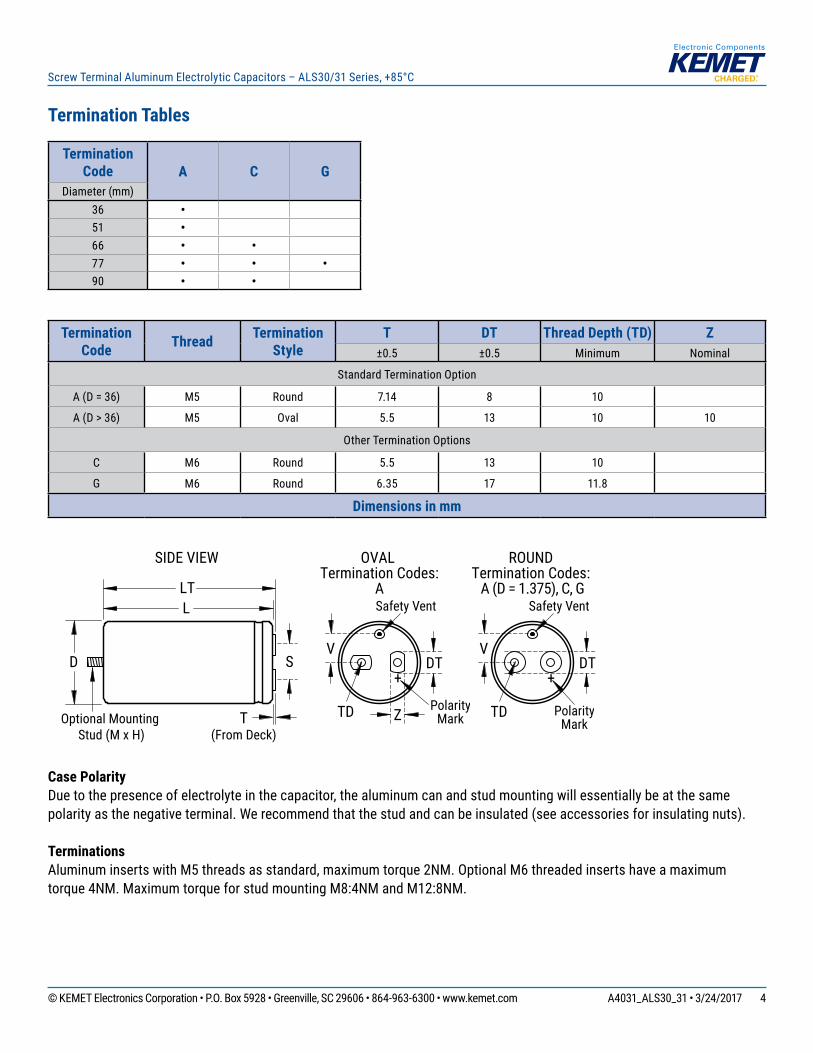
Termination Tables
Termination Code A C G
Diameter (mm)36 •51 •66 • •77 • • •90 • •
Termination Code Thread Termination
StyleT DT Thread Depth (TD) Z
±0.5 ±0.5 Minimum Nominal
Standard Termination Option
A (D = 36) M5 Round 7.14 8 10
A (D > 36) M5 Oval 5.5 13 10 10
Other Termination Options
C M6 Round 5.5 13 10
G M6 Round 6.35 17 11.8
Dimensions in mm
L
SIDE VIEW OVAL Termination Codes:
A
D
Optional Mounting Stud (M x H)
+DT
V
Safety Vent
TD PolarityMark
ROUND Termination Codes:
A (D = 1.375), C, G LT
S
T(From Deck)
+DT
V
Safety Vent
PolarityMarkZTD
Case PolarityDue to the presence of electrolyte in the capacitor, the aluminum can and stud mounting will essentially be at the same polarity as the negative terminal. We recommend that the stud and can be insulated (see accessories for insulating nuts).
TerminationsAluminum inserts with M5 threads as standard, maximum torque 2NM. Optional M6 threaded inserts have a maximum torque 4NM. Maximum torque for stud mounting M8:4NM and M12:8NM.
5© KEMET Electronics Corporation • P.O. Box 5928 • Greenville, SC 29606 • 864-963-6300 • www.kemet.com A4031_ALS30_31 • 3/24/2017
Screw Terminal Aluminum Electrolytic Capacitors – ALS30/31 Series, +85°C
Shelf Life
The capacitance, ESR and impedance of a capacitor will not change significantly after extended storage periods, however the leakage current will very slowly increase. KEMET products are particularly stable and allow a shelf life in excess of three years at 40°C. See sectional specification under each product series for specific data.
Re-age (Reforming) Procedure
Apply the rated voltage to the capacitor at room temperature for a period of one hour, or until the leakage current has fallen to a steady value below the specified limit. During re-aging a maximum charging current of twice the specified leakage current or 5 mA (whichever is greater) is suggested.
Reliability
The reliability of a component can be defined as the probability that it will perform satisfactorily under a given set of conditions for a given length of time. In practice, it is impossible to predict with absolute certainty how any individual component will perform; thus, we must utilize probability theory. It is also necessary to clearly define the level of stress involved (e.g. operating voltage, ripple current, temperature and time). Finally, the meaning of satisfactory performance must be defined by specifying a set of conditions which determine the end of life of the component. Reliability as a function of time, R(t), is normally expressed as: R(t)=e-λt where R(t) is the probability that the component will perform satisfactorily for time t, and λ is the failure rate.
Failure Rate
The failure rate is the number of components failing per unit time. The failure rate of most electronic components follows the characteristic pattern:
• Early failures are removed during the manufacturing process. • The operational life is characterized by a constant failure rate.• The wear out period is characterized by a rapidly increasing failure rate. The failures in time (FIT) are given with a 60% confidence level for the various type codes. By convention, FIT is expressed as 1 x 10⁻⁹ failures per hour. Failure rate is also expressed as a percentage of failures per 1,000 hours.e.g., 100 FIT = 1 x 10⁻⁷ failures per hour = 0.01%/1,000 hours
End of Life Definition Catastrophic Failure: short circuit, open circuit or safety vent operationParametric Failure:• Change in capacitance > ±10%• Leakage current > specified limit• ESR > 2 x initial ESR value
6© KEMET Electronics Corporation • P.O. Box 5928 • Greenville, SC 29606 • 864-963-6300 • www.kemet.com A4031_ALS30_31 • 3/24/2017
Screw Terminal Aluminum Electrolytic Capacitors – ALS30/31 Series, +85°C
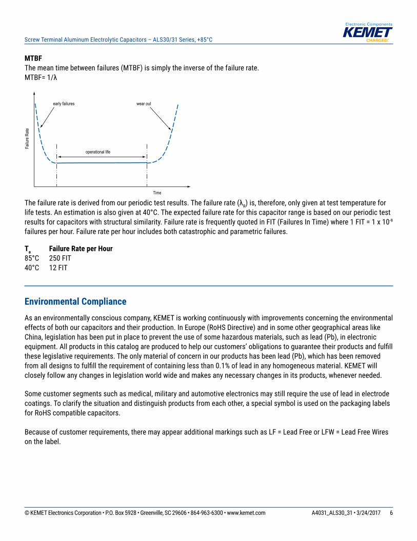
MTBFThe mean time between failures (MTBF) is simply the inverse of the failure rate. MTBF= 1/λ
wear outearly failures
operational life
Failu
re R
ate
Time
The failure rate is derived from our periodic test results. The failure rate (λR) is, therefore, only given at test temperature for life tests. An estimation is also given at 40°C. The expected failure rate for this capacitor range is based on our periodic test results for capacitors with structural similarity. Failure rate is frequently quoted in FIT (Failures In Time) where 1 FIT = 1 x 10⁻⁹ failures per hour. Failure rate per hour includes both catastrophic and parametric failures.
Ta Failure Rate per Hour85°C 250 FIT40°C 12 FIT
Environmental ComplianceAs an environmentally conscious company, KEMET is working continuously with improvements concerning the environmental effects of both our capacitors and their production. In Europe (RoHS Directive) and in some other geographical areas like China, legislation has been put in place to prevent the use of some hazardous materials, such as lead (Pb), in electronic equipment. All products in this catalog are produced to help our customers’ obligations to guarantee their products and fulfill these legislative requirements. The only material of concern in our products has been lead (Pb), which has been removed from all designs to fulfill the requirement of containing less than 0.1% of lead in any homogeneous material. KEMET will closely follow any changes in legislation world wide and makes any necessary changes in its products, whenever needed.
Some customer segments such as medical, military and automotive electronics may still require the use of lead in electrode coatings. To clarify the situation and distinguish products from each other, a special symbol is used on the packaging labels for RoHS compatible capacitors.
Because of customer requirements, there may appear additional markings such as LF = Lead Free or LFW = Lead Free Wires on the label.
7© KEMET Electronics Corporation • P.O. Box 5928 • Greenville, SC 29606 • 864-963-6300 • www.kemet.com A4031_ALS30_31 • 3/24/2017
Screw Terminal Aluminum Electrolytic Capacitors – ALS30/31 Series, +85°C
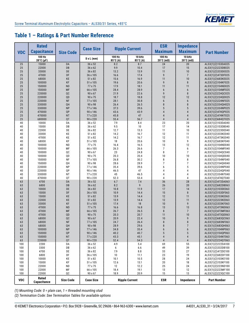
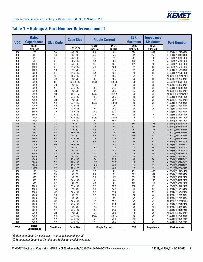
Table 1 – Ratings & Part Number Reference
(1) Mounting Code: 0 = plain can, 1 = threaded mounting stud(2) Termination Code: See Termination Tables for available options
VDCRated
Capacitance Size CodeCase Size Ripple Current ESR
MaximumImpedance Maximum Part Number
100 Hz 20°C (µF) D x L (mm) 100 Hz
85°C (A) 10 kHz
85°C (A)100 Hz
20°C (mΩ)10 kHz
20°C (mΩ)25 15000 DA 36 x 52 8.2 8.7 24 20 ALS3(1)(2)153DA02525 22000 DB 36 x 62 9.9 10.4 17 15 ALS3(1)(2)223DB02525 33000 DE 36 x 82 13.2 13.9 11 10 ALS3(1)(2)333DE02525 47000 DF 36 x 105 16.6 17.4 9 7 ALS3(1)(2)473DF02525 68000 KE 51 x 82 15.6 16.9 11 10 ALS3(1)(2)683KE02525 100000 KF 51 x 105 19.6 20.6 9 8 ALS3(1)(2)104KF02525 150000 ND 77 x 75 17.9 18.1 11 11 ALS3(1)(2)154ND02525 150000 MF 66 x 105 28.4 28.9 6 6 ALS3(1)(2)154MF02525 220000 QC 90 x 67 21.9 22.6 9 8 ALS3(1)(2)224QC02525 220000 QD 90 x 75 18.7 18.8 12 12 ALS3(1)(2)224QD02525 220000 NF 77 x 105 28.1 30.8 6 6 ALS3(1)(2)224NF02525 330000 QH 90 x 98 26.4 26.5 8 8 ALS3(1)(2)334QH02525 330000 NP 77 x 146 37.3 39.6 5 5 ALS3(1)(2)334NP02525 470000 QP 90 x 146 43.6 43.9 4 4 ALS3(1)(2)474QP02525 470000 NT 77 x 220 45.8 47 4 4 ALS3(1)(2)474NT02525 680000 QT 90 x 220 55.4 56.7 4 4 ALS3(1)(2)684QT02540 10000 DA 36 x 52 7.9 8.4 23 20 ALS3(1)(2)103DA04040 15000 DB 36 x 62 9.5 10 17 14 ALS3(1)(2)153DB04040 22000 DE 36 x 82 12.7 13.3 11 10 ALS3(1)(2)223DE04040 33000 KE 51 x 82 14.2 16.7 12 11 ALS3(1)(2)333KE04040 47000 KE 51 x 82 14.2 16.7 12 11 ALS3(1)(2)473KE04040 68000 KF 51 x 105 18 20.6 10 9 ALS3(1)(2)683KF04040 100000 ND 77 x 75 16.4 16.5 13 12 ALS3(1)(2)104ND04040 100000 MF 66 x 105 26.3 26.6 7 6 ALS3(1)(2)104MF04040 100000 QC 90 x 67 23 24.8 8 7 ALS3(1)(2)104QC04040 100000 QD 90 x 75 20.3 20.4 10 10 ALS3(1)(2)104QD04040 150000 NF 77 x 105 26.8 30.2 8 8 ALS3(1)(2)154NF04040 150000 QH 90 x 98 28.6 28.9 7 7 ALS3(1)(2)154QH04040 220000 NP 77 x 146 35.4 39.6 6 5 ALS3(1)(2)224NP04040 220000 QP 90 x 146 46.5 47 4 4 ALS3(1)(2)224QP04040 330000 NT 77 x 220 45 46.5 4 4 ALS3(1)(2)334NT04040 470000 QT 90 x 220 52.3 53.4 4 4 ALS3(1)(2)474QT04063 4700 DA 36 x 52 6.7 7.4 36 28 ALS3(1)(2)472DA06363 6800 DB 36 x 62 8.2 9 26 20 ALS3(1)(2)682DB06363 10000 DE 36 x 82 10.8 11.9 17 14 ALS3(1)(2)103DE06363 15000 DF 36 x 105 10.9 14.4 15 8 ALS3(1)(2)153DF06363 15000 KE 51 x 82 13.9 14.4 12 11 ALS3(1)(2)153KE06363 22000 KE 51 x 82 13.9 14.4 12 11 ALS3(1)(2)223KE06363 33000 KF 51 x 105 17.4 18 10 9 ALS3(1)(2)333KF06363 47000 ND 77 x 75 16.6 16.8 13 13 ALS3(1)(2)473ND06363 47000 MF 66 x 105 26.7 26.5 8 7 ALS3(1)(2)473MF06363 47000 QD 90 x 75 20.3 20.7 11 10 ALS3(1)(2)473QD06363 68000 QC 90 x 67 20.9 22.4 10 9 ALS3(1)(2)683QC06363 68000 NF 77 x 105 24.7 26.4 8 8 ALS3(1)(2)683NF06363 68000 QH 90 x 98 28.9 29.6 8 7 ALS3(1)(2)683QH06363 100000 NP 77 x 146 34.8 35.4 6 6 ALS3(1)(2)104NP06363 150000 QP 90 x 146 40.2 40.7 5 5 ALS3(1)(2)154QP06363 150000 NT 77 x 220 43.3 45.1 4 4 ALS3(1)(2)154NT06363 220000 QT 90 x 220 52.4 54.3 4 4 ALS3(1)(2)224QT063
100 2200 DA 36 x 52 4.9 5.4 69 55 ALS3(1)(2)222DA100100 3300 DB 36 x 62 6 6.6 49 39 ALS3(1)(2)332DB100100 4700 DE 36 x 82 7.9 8.8 33 27 ALS3(1)(2)472DE100100 6800 DF 36 x 105 10 11.1 23 19 ALS3(1)(2)682DF100100 10000 KE 51 x 82 10.1 10.5 28 24 ALS3(1)(2)103KE100100 15000 KF 51 x 105 12.6 13.1 20 18 ALS3(1)(2)153KF100100 22000 ND 77 x 75 12 12.2 25 24 ALS3(1)(2)223ND100100 22000 MF 66 x 105 18.4 19.1 13 12 ALS3(1)(2)223MF100100 22000 QC 90 x 67 18.9 20.9 15 13 ALS3(1)(2)223QC100
VDC Rated Capacitance Size Code Case Size Ripple Current ESR Impedance Part Number
8© KEMET Electronics Corporation • P.O. Box 5928 • Greenville, SC 29606 • 864-963-6300 • www.kemet.com A4031_ALS30_31 • 3/24/2017
Screw Terminal Aluminum Electrolytic Capacitors – ALS30/31 Series, +85°C
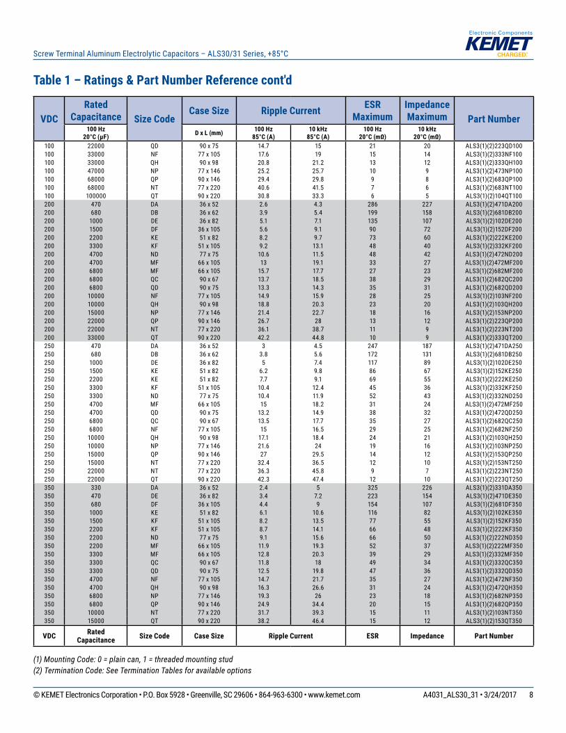
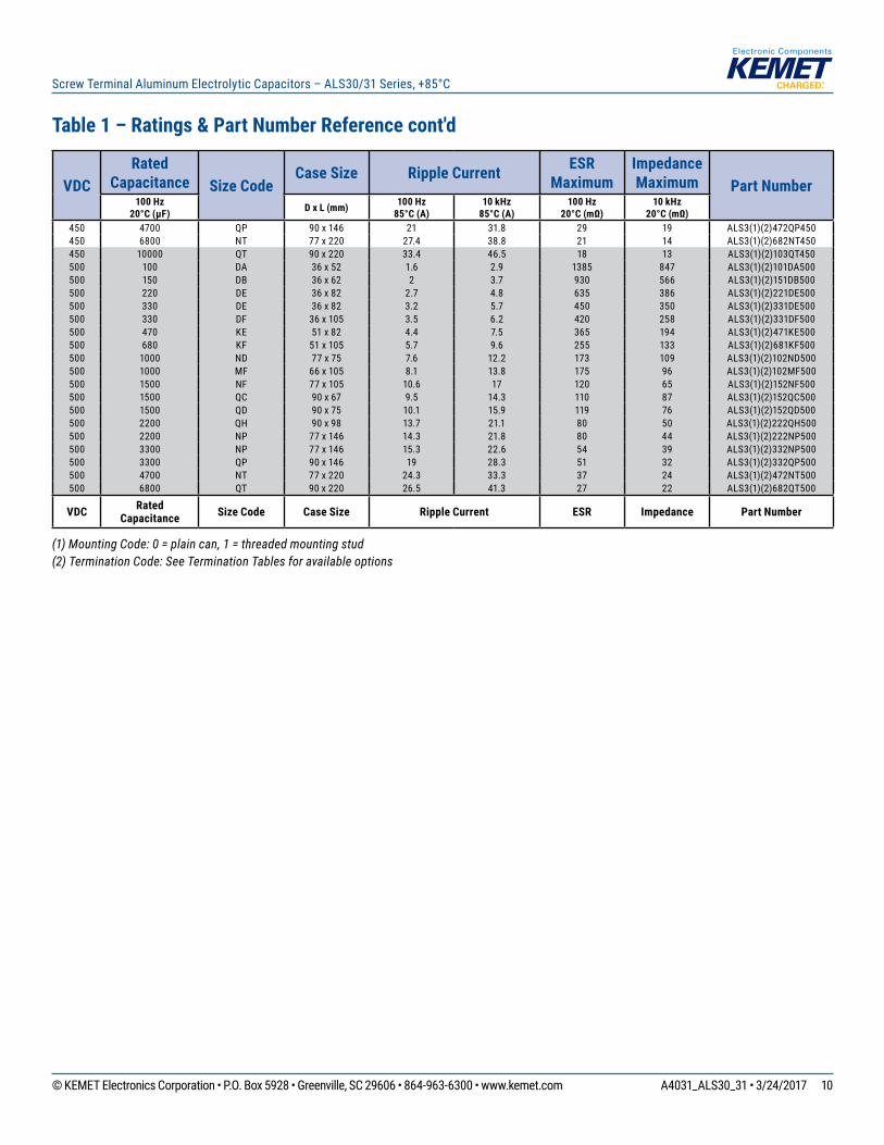
Table 1 – Ratings & Part Number Reference cont'd
(1) Mounting Code: 0 = plain can, 1 = threaded mounting stud(2) Termination Code: See Termination Tables for available options
VDCRated
Capacitance Size CodeCase Size Ripple Current ESR
MaximumImpedance Maximum Part Number
100 Hz 20°C (µF) D x L (mm) 100 Hz
85°C (A) 10 kHz
85°C (A)100 Hz
20°C (mΩ)10 kHz
20°C (mΩ)100 22000 QD 90 x 75 14.7 15 21 20 ALS3(1)(2)223QD100100 33000 NF 77 x 105 17.6 19 15 14 ALS3(1)(2)333NF100100 33000 QH 90 x 98 20.8 21.2 13 12 ALS3(1)(2)333QH100100 47000 NP 77 x 146 25.2 25.7 10 9 ALS3(1)(2)473NP100100 68000 QP 90 x 146 29.4 29.8 9 8 ALS3(1)(2)683QP100100 68000 NT 77 x 220 40.6 41.5 7 6 ALS3(1)(2)683NT100100 100000 QT 90 x 220 30.8 33.3 6 5 ALS3(1)(2)104QT100200 470 DA 36 x 52 2.6 4.3 286 227 ALS3(1)(2)471DA200200 680 DB 36 x 62 3.9 5.4 199 158 ALS3(1)(2)681DB200200 1000 DE 36 x 82 5.1 7.1 135 107 ALS3(1)(2)102DE200200 1500 DF 36 x 105 5.6 9.1 90 72 ALS3(1)(2)152DF200200 2200 KE 51 x 82 8.2 9.7 73 60 ALS3(1)(2)222KE200200 3300 KF 51 x 105 9.2 13.1 48 40 ALS3(1)(2)332KF200200 4700 ND 77 x 75 10.6 11.5 48 42 ALS3(1)(2)472ND200200 4700 MF 66 x 105 13 19.1 33 27 ALS3(1)(2)472MF200200 6800 MF 66 x 105 15.7 17.7 27 23 ALS3(1)(2)682MF200200 6800 QC 90 x 67 13.7 18.5 38 29 ALS3(1)(2)682QC200200 6800 QD 90 x 75 13.3 14.3 35 31 ALS3(1)(2)682QD200200 10000 NF 77 x 105 14.9 15.9 28 25 ALS3(1)(2)103NF200200 10000 QH 90 x 98 18.8 20.3 23 20 ALS3(1)(2)103QH200200 15000 NP 77 x 146 21.4 22.7 18 16 ALS3(1)(2)153NP200200 22000 QP 90 x 146 26.7 28 13 12 ALS3(1)(2)223QP200200 22000 NT 77 x 220 36.1 38.7 11 9 ALS3(1)(2)223NT200200 33000 QT 90 x 220 42.2 44.8 10 9 ALS3(1)(2)333QT200250 470 DA 36 x 52 3 4.5 247 187 ALS3(1)(2)471DA250250 680 DB 36 x 62 3.8 5.6 172 131 ALS3(1)(2)681DB250250 1000 DE 36 x 82 5 7.4 117 89 ALS3(1)(2)102DE250250 1500 KE 51 x 82 6.2 9.8 86 67 ALS3(1)(2)152KE250250 2200 KE 51 x 82 7.7 9.1 69 55 ALS3(1)(2)222KE250250 3300 KF 51 x 105 10.4 12.4 45 36 ALS3(1)(2)332KF250250 3300 ND 77 x 75 10.4 11.9 52 43 ALS3(1)(2)332ND250250 4700 MF 66 x 105 15 18.2 31 24 ALS3(1)(2)472MF250250 4700 QD 90 x 75 13.2 14.9 38 32 ALS3(1)(2)472QD250250 6800 QC 90 x 67 13.5 17.7 35 27 ALS3(1)(2)682QC250250 6800 NF 77 x 105 15 16.5 29 25 ALS3(1)(2)682NF250250 10000 QH 90 x 98 17.1 18.4 24 21 ALS3(1)(2)103QH250250 10000 NP 77 x 146 21.6 24 19 16 ALS3(1)(2)103NP250250 15000 QP 90 x 146 27 29.5 14 12 ALS3(1)(2)153QP250250 15000 NT 77 x 220 32.4 36.5 12 10 ALS3(1)(2)153NT250250 22000 NT 77 x 220 36.3 45.8 9 7 ALS3(1)(2)223NT250250 22000 QT 90 x 220 42.3 47.4 12 10 ALS3(1)(2)223QT250350 330 DA 36 x 52 2.4 5 325 226 ALS3(1)(2)331DA350350 470 DE 36 x 82 3.4 7.2 223 154 ALS3(1)(2)471DE350350 680 DF 36 x 105 4.4 9 154 107 ALS3(1)(2)681DF350350 1000 KE 51 x 82 6.1 10.6 116 82 ALS3(1)(2)102KE350350 1500 KF 51 x 105 8.2 13.5 77 55 ALS3(1)(2)152KF350350 2200 KF 51 x 105 8.7 14.1 66 48 ALS3(1)(2)222KF350350 2200 ND 77 x 75 9.1 15.6 66 50 ALS3(1)(2)222ND350350 2200 MF 66 x 105 11.9 19.3 52 37 ALS3(1)(2)222MF350350 3300 MF 66 x 105 12.8 20.3 39 29 ALS3(1)(2)332MF350350 3300 QC 90 x 67 11.8 18 49 34 ALS3(1)(2)332QC350350 3300 QD 90 x 75 12.5 19.8 47 36 ALS3(1)(2)332QD350350 4700 NF 77 x 105 14.7 21.7 35 27 ALS3(1)(2)472NF350350 4700 QH 90 x 98 16.3 26.6 31 24 ALS3(1)(2)472QH350350 6800 NP 77 x 146 19.3 26 23 18 ALS3(1)(2)682NP350350 6800 QP 90 x 146 24.9 34.4 20 15 ALS3(1)(2)682QP350350 10000 NT 77 x 220 31.7 39.3 15 11 ALS3(1)(2)103NT350350 15000 QT 90 x 220 38.2 46.4 15 12 ALS3(1)(2)153QT350
VDC Rated Capacitance Size Code Case Size Ripple Current ESR Impedance Part Number
9© KEMET Electronics Corporation • P.O. Box 5928 • Greenville, SC 29606 • 864-963-6300 • www.kemet.com A4031_ALS30_31 • 3/24/2017
Screw Terminal Aluminum Electrolytic Capacitors – ALS30/31 Series, +85°C
Table 1 – Ratings & Part Number Reference cont'd
(1) Mounting Code: 0 = plain can, 1 = threaded mounting stud(2) Termination Code: See Termination Tables for available options
VDCRated
Capacitance Size CodeCase Size Ripple Current ESR
MaximumImpedance Maximum Part Number
100 Hz 20°C (µF) D x L (mm) 100 Hz
85°C (A) 10 kHz
85°C (A)100 Hz
20°C (mΩ)10 kHz
20°C (mΩ)400 220 DA 36 x 52 2.1 4.4 570 387 ALS3(1)(2)221DA400400 330 DB 36 x 62 2.7 5.5 382 260 ALS3(1)(2)331DB400400 470 DE 36 x 82 3.5 7.1 267 182 ALS3(1)(2)471DE400400 680 DF 36 x 105 4.4 8.8 185 126 ALS3(1)(2)681DF400400 1000 KE 51 x 82 5.8 10.3 139 98 ALS3(1)(2)102KE400400 1500 KF 51 x 105 7.8 13.1 92 65 ALS3(1)(2)152KF400400 1500 ND 77 x 75 8.3 14.7 97 70 ALS3(1)(2)152ND400400 2200 KF 51 x 105 8.4 13.5 78 56 ALS3(1)(2)222KF400400 2200 MF 66 x 105 11.2 18.8 62 44 ALS3(1)(2)222MF400400 2200 QD 90 x 75 10.7 18.9 69 50 ALS3(1)(2)222QD400400 3300 LF 63.5 X 10⁵ 11.81 20.54 54 36 ALS3(1)(2)332LF400400 3300 QC 90 x 67 11.7 17.1 53 38 ALS3(1)(2)332QC400400 3300 NF 77 x 105 13.4 21.3 49 36 ALS3(1)(2)332NF400400 3300 QH 90 x 98 14.9 25.3 45 32 ALS3(1)(2)332QH400400 3900 MJ 66 x 115 12.98 21.02 50 35 ALS3(1)(2)392MJ400400 4700 NF 77 x 105 14.6 20.9 38 26 ALS3(1)(2)472NF400400 4700 QH 90 x 98 17.1 25.4 36 26 ALS3(1)(2)472QH400400 4700 NJ 77 X 115 15.25 23.20 38 26 ALS3(1)(2)472NJ400400 4700 NP 77 x 146 18 26 33 24 ALS3(1)(2)472NP400400 6800 NP 77 x 146 19.5 26.9 27 20 ALS3(1)(2)682NP400400 6800 QP 90 x 146 23.2 32.9 24 17 ALS3(1)(2)682QP400400 6800 NT 77 x 220 29 40.7 22 15 ALS3(1)(2)682NT400400 10000 NT 77 X 220 31.50 42.00 19 14 ALS3(1)(2)103NT400400 10000 QT 90 x 220 35.7 49.4 17 12 ALS3(1)(2)103QT400415 220 DA 36 x 52 2.1 4.4 555 368 ALS3(1)(2)221DA415415 330 DB 36 x 62 2.7 5.6 372 247 ALS3(1)(2)331DB415415 470 DE 36 x 82 3.5 7.2 261 173 ALS3(1)(2)471DE415415 680 DF 36 x 105 4.5 9 180 120 ALS3(1)(2)681DF415415 1000 KE 51 x 82 5.7 10.4 136 94 ALS3(1)(2)102KE415415 1500 KF 51 x 105 7.6 13.1 90 62 ALS3(1)(2)152KF415415 1500 ND 77 x 75 8.1 14.7 96 68 ALS3(1)(2)152ND415415 2200 MF 66 x 105 11 18.9 61 42 ALS3(1)(2)222MF415415 2200 QC 90 x 67 10.5 17.5 71 49 ALS3(1)(2)222QC415415 2200 QD 90 x 75 11.1 18.9 68 49 ALS3(1)(2)222QD415415 3300 NF 77 x 105 13.4 21.3 48 36 ALS3(1)(2)332NF415415 3300 QH 90 x 98 14.6 25.3 45 32 ALS3(1)(2)332QH415415 4700 NP 77 x 146 17.6 25.9 33 24 ALS3(1)(2)472NP415415 6800 QP 90 x 146 22.7 32.8 23 17 ALS3(1)(2)682QP415415 6800 NT 77 x 220 28.5 40.1 21 15 ALS3(1)(2)682NT415415 10000 QT 90 x 220 35.2 48.7 17 12 ALS3(1)(2)103QT415450 150 DA 36 x 52 1.8 4.1 735 485 ALS3(1)(2)151DA450450 220 DB 36 x 62 2.4 5.1 502 332 ALS3(1)(2)221DB450450 330 DE 36 x 82 3.1 6.7 335 221 ALS3(1)(2)331DE450450 470 DF 36 x 105 4 8.4 235 155 ALS3(1)(2)471DF450450 680 KE 51 x 82 4.9 9.9 175 117 ALS3(1)(2)681KE450450 1000 KF 51 x 105 6.5 12.6 118 79 ALS3(1)(2)102KF450450 1500 ND 77 x 75 8.7 14.9 95 65 ALS3(1)(2)152ND450450 1500 MF 66 x 105 9.5 17.4 81 52 ALS3(1)(2)152MF450450 2200 QC 90 x 67 9.6 15.4 74 46 ALS3(1)(2)222QC450450 2200 QD 90 x 75 11.5 19 67 47 ALS3(1)(2)222QD450450 2200 MF 66 x 105 11.1 19.3 67 47 ALS3(1)(2)222MF450450 2200 NF 77 x 105 12.2 21.1 59 41 ALS3(1)(2)222NF450450 3300 QD 90 x 75 12.6 17.9 53 33 ALS3(1)(2)332QD450450 3300 NF 77 x 105 13.8 21.2 40 30 ALS3(1)(2)332NF450450 3300 QH 90 x 98 15.6 25.5 44 30 ALS3(1)(2)332QH450450 4700 NJ 77 X 115 14.93 22.76 30 20 ALS3(1)(2)472NJ450450 3300 NP 77 x 146 16.1 25.1 39 27 ALS3(1)(2)332NP450450 4700 NP 77 x 146 17.1 25.2 36 26 ALS3(1)(2)472NP450
VDC Rated Capacitance Size Code Case Size Ripple Current ESR Impedance Part Number
10© KEMET Electronics Corporation • P.O. Box 5928 • Greenville, SC 29606 • 864-963-6300 • www.kemet.com A4031_ALS30_31 • 3/24/2017
Screw Terminal Aluminum Electrolytic Capacitors – ALS30/31 Series, +85°C
VDCRated
Capacitance Size CodeCase Size Ripple Current ESR
MaximumImpedance Maximum Part Number
100 Hz 20°C (µF) D x L (mm) 100 Hz
85°C (A) 10 kHz
85°C (A)100 Hz
20°C (mΩ)10 kHz
20°C (mΩ)450 4700 QP 90 x 146 21 31.8 29 19 ALS3(1)(2)472QP450450 6800 NT 77 x 220 27.4 38.8 21 14 ALS3(1)(2)682NT450450 10000 QT 90 x 220 33.4 46.5 18 13 ALS3(1)(2)103QT450500 100 DA 36 x 52 1.6 2.9 1385 847 ALS3(1)(2)101DA500500 150 DB 36 x 62 2 3.7 930 566 ALS3(1)(2)151DB500500 220 DE 36 x 82 2.7 4.8 635 386 ALS3(1)(2)221DE500500 330 DE 36 x 82 3.2 5.7 450 350 ALS3(1)(2)331DE500500 330 DF 36 x 105 3.5 6.2 420 258 ALS3(1)(2)331DF500500 470 KE 51 x 82 4.4 7.5 365 194 ALS3(1)(2)471KE500500 680 KF 51 x 105 5.7 9.6 255 133 ALS3(1)(2)681KF500500 1000 ND 77 x 75 7.6 12.2 173 109 ALS3(1)(2)102ND500500 1000 MF 66 x 105 8.1 13.8 175 96 ALS3(1)(2)102MF500500 1500 NF 77 x 105 10.6 17 120 65 ALS3(1)(2)152NF500500 1500 QC 90 x 67 9.5 14.3 110 87 ALS3(1)(2)152QC500500 1500 QD 90 x 75 10.1 15.9 119 76 ALS3(1)(2)152QD500500 2200 QH 90 x 98 13.7 21.1 80 50 ALS3(1)(2)222QH500500 2200 NP 77 x 146 14.3 21.8 80 44 ALS3(1)(2)222NP500500 3300 NP 77 x 146 15.3 22.6 54 39 ALS3(1)(2)332NP500500 3300 QP 90 x 146 19 28.3 51 32 ALS3(1)(2)332QP500500 4700 NT 77 x 220 24.3 33.3 37 24 ALS3(1)(2)472NT500500 6800 QT 90 x 220 26.5 41.3 27 22 ALS3(1)(2)682QT500
VDC Rated Capacitance Size Code Case Size Ripple Current ESR Impedance Part Number
Table 1 – Ratings & Part Number Reference cont'd
(1) Mounting Code: 0 = plain can, 1 = threaded mounting stud(2) Termination Code: See Termination Tables for available options
11© KEMET Electronics Corporation • P.O. Box 5928 • Greenville, SC 29606 • 864-963-6300 • www.kemet.com A4031_ALS30_31 • 3/24/2017
Screw Terminal Aluminum Electrolytic Capacitors – ALS30/31 Series, +85°C
Mechanical Data
Polarity and Reversed VoltageAluminium Electrolytic capacitors manufactured for use in DC applications contain an anode foil and a cathode foil. As such, they are polarized devices and must be connected with the +ve to the anode foil and the -ve to the cathode foil. If this were to be reversed then the electrolytic process that took place in forming the oxide layer on the anode would be recreated in trying to form an oxide layer on the cathode. In forming the cathode foil in this way, heat would be generated and gas given off within the capacitor, usually leading to catastrophic failure. The cathode foil already possesses a thin stabilized oxide layer. This thin oxide layer is equivalent to a forming voltage of approximately 2 V. As a result, the capacitor can withstand a voltage reversal of up to 2 V for short periods. Above this voltage, the formation process will commence. Aluminium Electrolytic capacitors can also be manufactured for use in intermittent AC applications by using two anode foils in place of one anode and one cathode.
Mounting PositionThe capacitor can be mounted in any position as long as the safety vent can operate. It is possible for some electrolyte to be expelled. As this is a conducting liquid, suitable precautions should be initiated by the system designer to avoid secondary short circuits.The capacitors are designed to be mounted in free air and are not suitable for submersion in liquid. Low Inductance VersionA low inductance version of the ALS30/31 capacitors can be designed upon request, typically reducing the inductance by up to 40% of the standard capacitor's inductance. It is available in 77 & 90 mm diameters.
Insulating Resistance≥ 100 MΩ at 100 VDC across insulating sleeve. UL recognized sleeving is available for custom parts in this range, upon request. (UL No. E358957) Voltage Proof≥ 2,500 VDC across insulating sleeve Safety VentA safety vent for overpressure is featured on terminal deck. This is in the form of a rubber plug designed to relieve build-up of internal pressure due to overstress or catastrophic failure.
12© KEMET Electronics Corporation • P.O. Box 5928 • Greenville, SC 29606 • 864-963-6300 • www.kemet.com A4031_ALS30_31 • 3/24/2017
Screw Terminal Aluminum Electrolytic Capacitors – ALS30/31 Series, +85°C
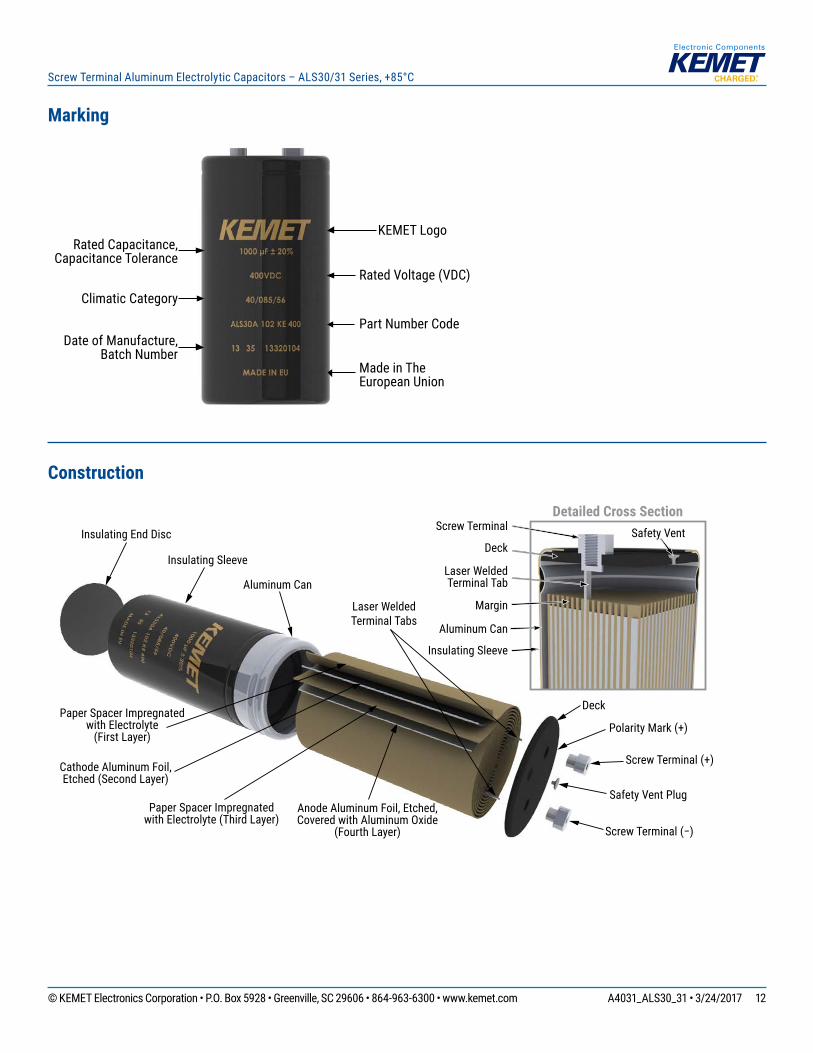
Marking
KEMET LogoRated Capacitance,
Capacitance ToleranceRated Voltage (VDC)
Climatic Category
Part Number Code
Made in The European Union
Date of Manufacture, Batch Number
Construction
Detailed Cross Section
Margin
Safety VentScrew Terminal
Laser Welded Terminal Tab
Aluminum Can
Insulating Sleeve
Deck
Insulating Sleeve
Aluminum Can
Laser Welded Terminal Tabs
Deck
Screw Terminal (+)
Screw Terminal (−)
Polarity Mark (+)
Safety Vent Plug
Insulating End Disc
Anode Aluminum Foil, Etched, Covered with Aluminum Oxide
(Fourth Layer)
Cathode Aluminum Foil, Etched (Second Layer)
Paper Spacer Impregnatedwith Electrolyte
(First Layer)
Paper Spacer Impregnated with Electrolyte (Third Layer)
13© KEMET Electronics Corporation • P.O. Box 5928 • Greenville, SC 29606 • 864-963-6300 • www.kemet.com A4031_ALS30_31 • 3/24/2017
Screw Terminal Aluminum Electrolytic Capacitors – ALS30/31 Series, +85°C
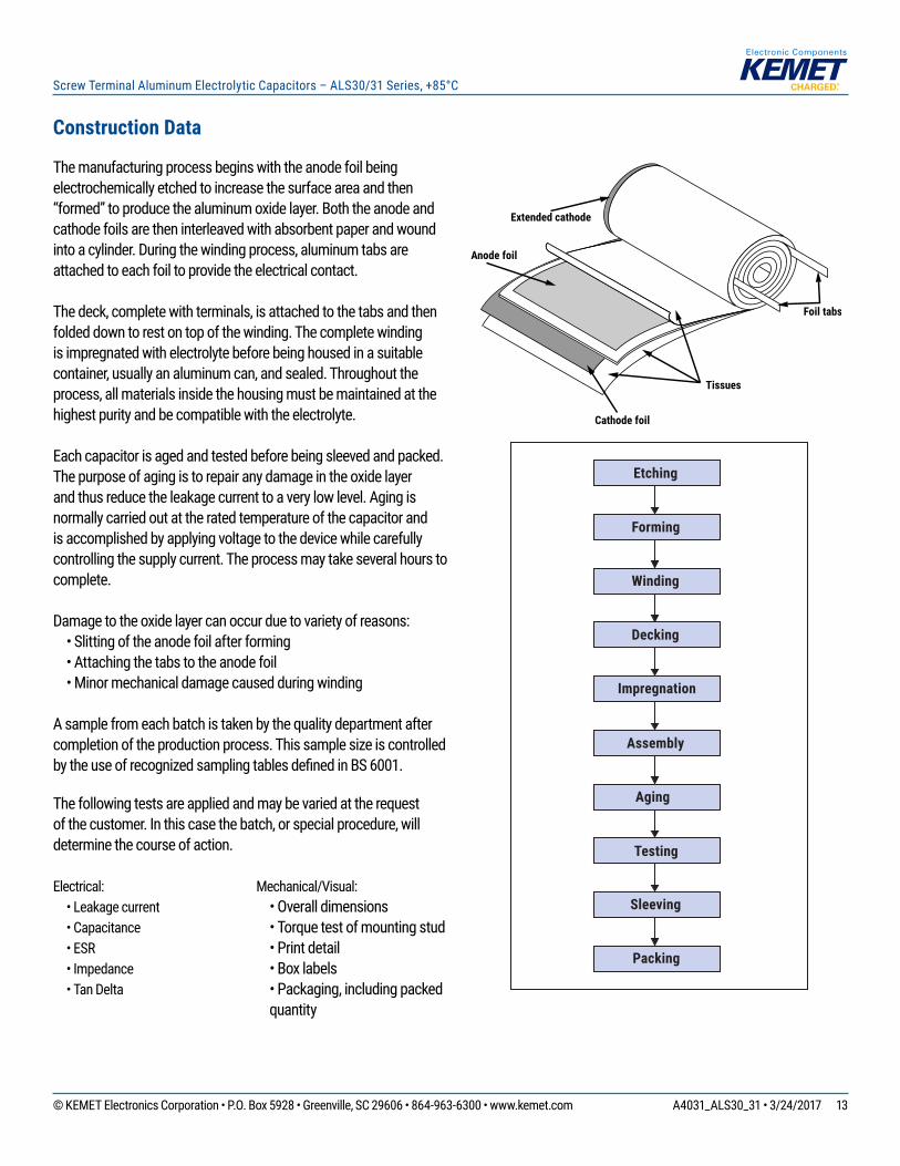
Extended cathode
Anode foil
Cathode foil
Tissues
Foil tabs
Aging
Etching
Forming
Winding
Decking
Impregnation
Assembly
Testing
Sleeving
Packing
Construction Data
The manufacturing process begins with the anode foil being electrochemically etched to increase the surface area and then “formed” to produce the aluminum oxide layer. Both the anode and cathode foils are then interleaved with absorbent paper and wound into a cylinder. During the winding process, aluminum tabs are attached to each foil to provide the electrical contact.
The deck, complete with terminals, is attached to the tabs and then folded down to rest on top of the winding. The complete winding is impregnated with electrolyte before being housed in a suitable container, usually an aluminum can, and sealed. Throughout the process, all materials inside the housing must be maintained at the highest purity and be compatible with the electrolyte.
Each capacitor is aged and tested before being sleeved and packed. The purpose of aging is to repair any damage in the oxide layer and thus reduce the leakage current to a very low level. Aging is normally carried out at the rated temperature of the capacitor and is accomplished by applying voltage to the device while carefully controlling the supply current. The process may take several hours to complete.
Damage to the oxide layer can occur due to variety of reasons: • Slitting of the anode foil after forming • Attaching the tabs to the anode foil • Minor mechanical damage caused during winding
A sample from each batch is taken by the quality department after completion of the production process. This sample size is controlled by the use of recognized sampling tables defi ned in BS 6001.
The following tests are applied and may be varied at the request of the customer. In this case the batch, or special procedure, will determine the course of action.
Electrical: • Leakage current • Capacitance • ESR • Impedance • Tan Delta
Mechanical/Visual: • Overall dimensions • Torque test of mounting stud • Print detail • Box labels • Packaging, including packed
quantity
14© KEMET Electronics Corporation • P.O. Box 5928 • Greenville, SC 29606 • 864-963-6300 • www.kemet.com A4031_ALS30_31 • 3/24/2017
Screw Terminal Aluminum Electrolytic Capacitors – ALS30/31 Series, +85°C
KEMET Electronic Corporation Sales Offi ces
For a complete list of our global sales offi ces, please visit www.kemet.com/sales.
DisclaimerAll product specifi cations, statements, information and data (collectively, the “Information”) in this datasheet are subject to change. The customer is responsible for checking and verifying the extent to which the Information contained in this publication is applicable to an order at the time the order is placed.
All Information given herein is believed to be accurate and reliable, but it is presented without guarantee, warranty, or responsibility of any kind, expressed or implied.
Statements of suitability for certain applications are based on KEMET Electronics Corporation’s (“KEMET”) knowledge of typical operating conditions for such applications, but are not intended to constitute – and KEMET specifi cally disclaims – any warranty concerning suitability for a specifi c customer application or use. The Information is intended for use only by customers who have the requisite experience and capability to determine the correct products for their application. Any technical advice inferred from this Information or otherwise provided by KEMET with reference to the use of KEMET’s products is given gratis, and KEMET assumes no obligation or liability for the advice given or results obtained.
Although KEMET designs and manufactures its products to the most stringent quality and safety standards, given the current state of the art, isolated component failures may still occur. Accordingly, customer applications which require a high degree of reliability or safety should employ suitable designs or other safeguards (such as installation of protective circuitry or redundancies) in order to ensure that the failure of an electrical component does not result in a risk of personal injury or property damage.
Although all product–related warnings, cautions and notes must be observed, the customer should not assume that all safety measures are indicted or that other measures may not be required.
KEMET is a registered trademark of KEMET Electronics Corporation.


