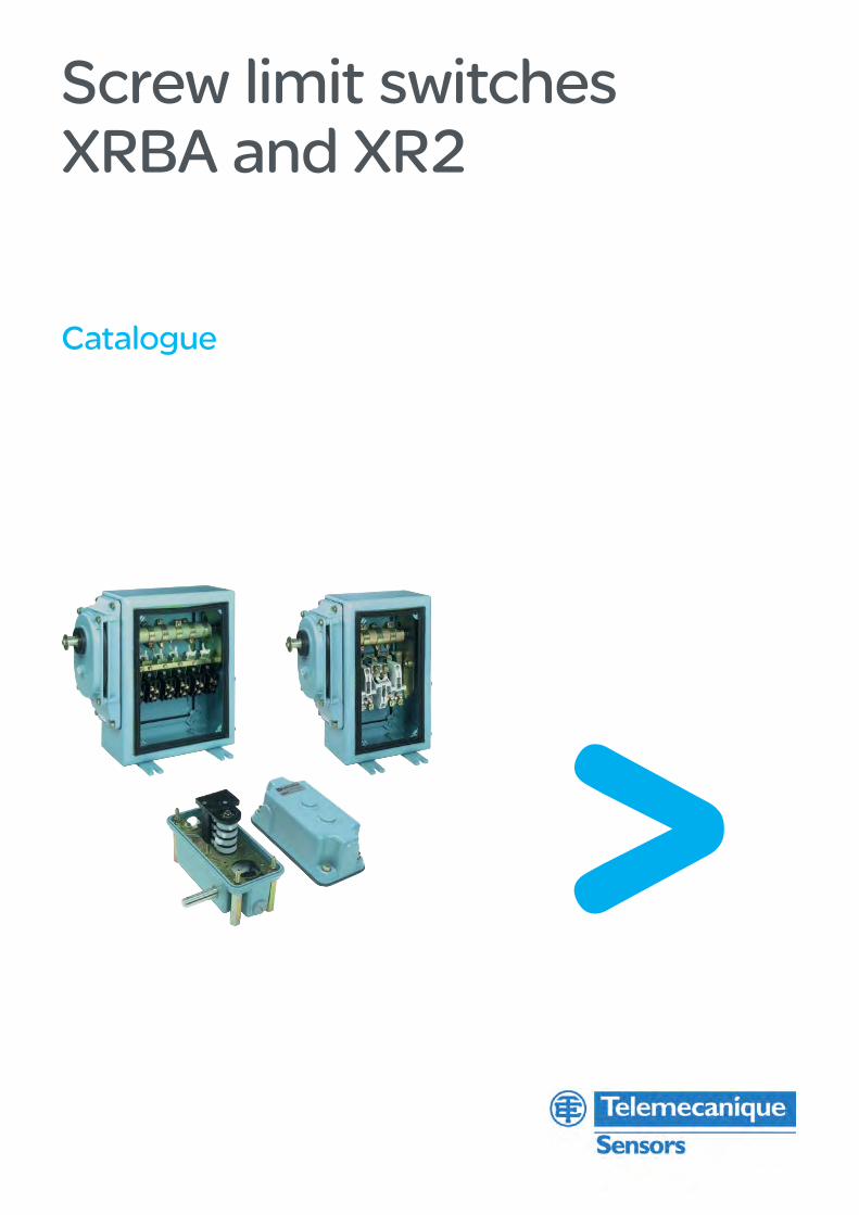
Screw limit switchesXRBA and XR2
Catalogue

1
Screw limit switchesXRBA and XR2
Selection guide . . . . . . . . . . . . . . . . . . . . . . . . . . . . . . . . . . . . . . . . . . . . . . page 2
■ Screw limit switches for standard duty: XRBA □ Presentation . . . . . . . . . . . . . . . . . . . . . . . . . . . . . . . . . . . . . . . . . . . . . . page 4 □ Characteristics . . . . . . . . . . . . . . . . . . . . . . . . . . . . . . . . . . . . . . . . . . . . . page 5 □ References . . . . . . . . . . . . . . . . . . . . . . . . . . . . . . . . . . . . . . . . . . . . . . . page 6 □ Order form . . . . . . . . . . . . . . . . . . . . . . . . . . . . . . . . . . . . . . . . . . . . . . . . page 7 □ Screw limit switch selection example . . . . . . . . . . . . . . . . . . . . . . pages 8 and 9 □ Dimensions . . . . . . . . . . . . . . . . . . . . . . . . . . . . . . . . . . . . . . . . . . . . . . page 18
■ Screw limit switches for heavy duty: XR2 □ Presentation . . . . . . . . . . . . . . . . . . . . . . . . . . . . . . . . . . . . . . . . . . . . . page 10 □ Characteristics . . . . . . . . . . . . . . . . . . . . . . . . . . . . . . . . . . . . . pages 11 and 12 □ References . . . . . . . . . . . . . . . . . . . . . . . . . . . . . . . . . . . . . . . . .pages 13 to 15 □ Dimensions . . . . . . . . . . . . . . . . . . . . . . . . . . . . . . . . . . . . . . . . . . . . . . page 18
■ Differential drive units □ Presentation and references . . . . . . . . . . . . . . . . . . . . . . . . . . . . . . . . . page 17 □ Dimensions and mounting . . . . . . . . . . . . . . . . . . . . . . . . . . . . . . . . . . . page 19
Contents
2
1
3
4
5
6
7
8
9
10
2
1
3
4
5
6
7
8
9
10
2
Screw limit switches
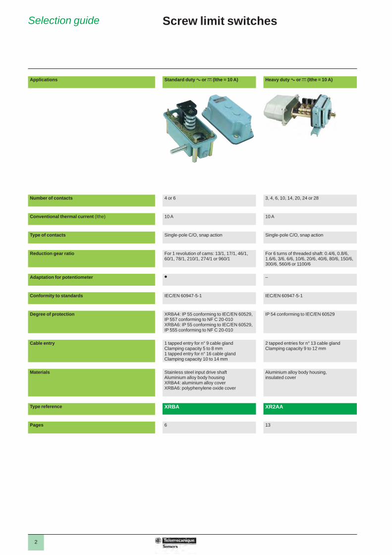
Applications Standard duty a or c (Ithe = 10 A) Heavy duty a or c (Ithe = 10 A)
Number of contacts 4 or 6 3, 4, 6, 10, 14, 20, 24 or 28
Conventional thermal current (Ithe) 10 A 10 A
Type of contacts Single-pole C/O, snap action Single-pole C/O, snap action
Reduction gear ratio For 1 revolution of cams: 13/1, 17/1, 46/1, 60/1, 78/1, 210/1, 274/1 or 960/1
For 6 turns of threaded shaft: 0.4/6, 0.8/6, 1.6/6, 3/6, 6/6, 10/6, 20/6, 40/6, 80/6, 150/6, 300/6, 560/6 or 1100/6
Adaptation for potentiometer p –
Conformity to standards IEC/EN 60947-5-1 IEC/EN 60947-5-1
Degree of protection XRBA4: IP 55 conforming to IEC/EN 60529, IP 557 conforming to NF C 20-010XRBA6: IP 55 conforming to IEC/EN 60529, IP 555 conforming to NF C 20-010
IP 54 conforming to IEC/EN 60529
Cable entry 1 tapped entry for n° 9 cable glandClamping capacity 5 to 8 mm1 tapped entry for n° 16 cable glandClamping capacity 10 to 14 mm
2 tapped entries for n° 13 cable glandClamping capacity 9 to 12 mm
Materials Stainless steel input drive shaft Aluminium alloy body housingXRBA4: aluminium alloy coverXRBA6: polyphenylene oxide cover
Aluminium alloy body housing, insulated cover
Type reference XRBA XR2AA
Pages 6 13
Selection guide
3
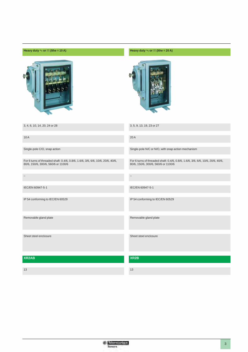
Heavy duty a or c (Ithe = 10 A) Heavy duty a or c (Ithe = 20 A)
3, 4, 6, 10, 14, 20, 24 or 28 3, 5, 9, 13, 19, 23 or 27
10 A 20 A
Single-pole C/O, snap action Single-pole N/C or N/O, with snap action mechanism
For 6 turns of threaded shaft: 0.4/6, 0.8/6, 1.6/6, 3/6, 6/6, 10/6, 20/6, 40/6, 80/6, 150/6, 300/6, 560/6 or 1100/6
For 6 turns of threaded shaft: 0.4/6, 0.8/6, 1.6/6, 3/6, 6/6, 10/6, 20/6, 40/6, 80/6, 150/6, 300/6, 560/6 or 1100/6
– –
IEC/EN 60947-5-1 IEC/EN 60947-5-1
IP 54 conforming to IEC/EN 60529 IP 54 conforming to IEC/EN 60529
Removable gland plate Removable gland plate
Sheet steel enclosure Sheet steel enclosure
XR2AB XR2B
13 13
4
Screw limit switchesStandard duty, XRBA
Functions
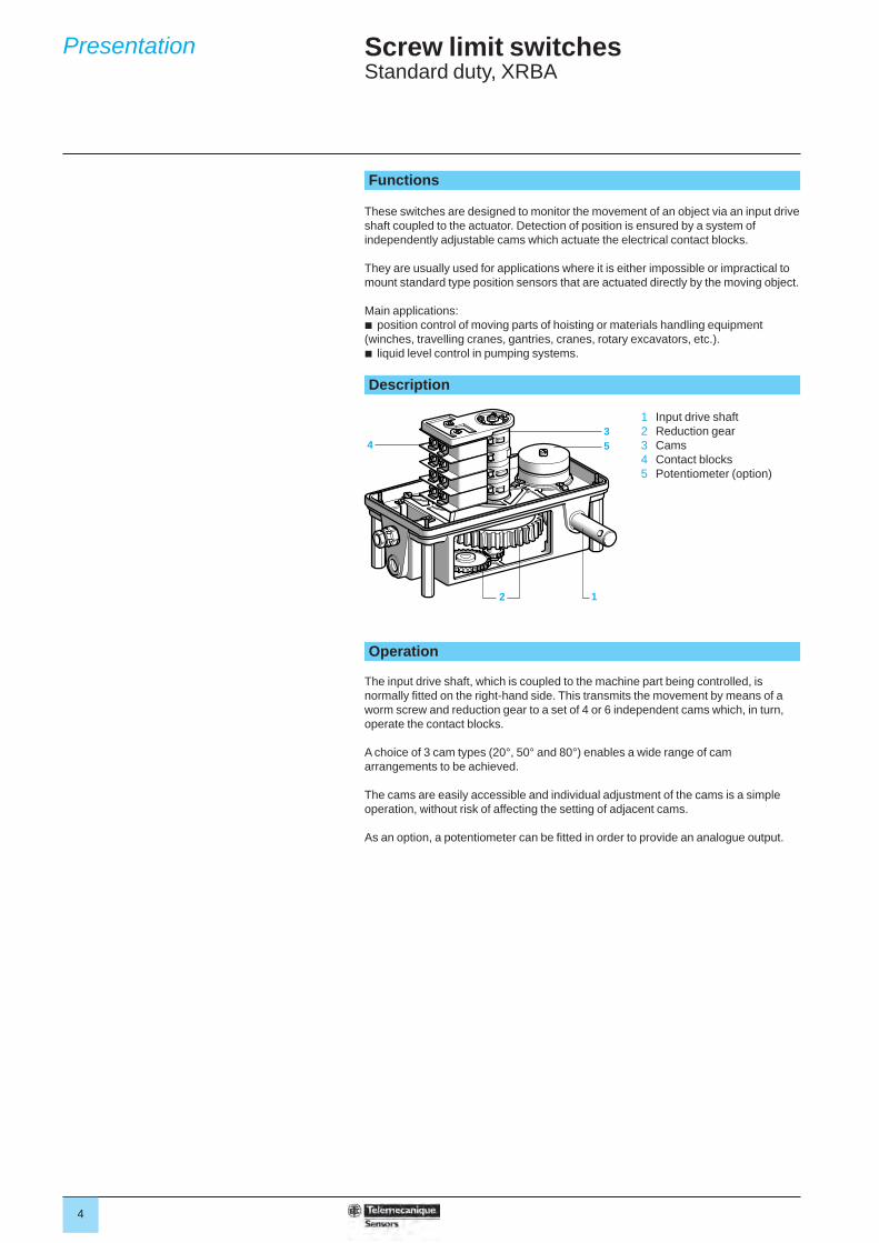
These switches are designed to monitor the movement of an object via an input drive shaft coupled to the actuator. Detection of position is ensured by a system of independently adjustable cams which actuate the electrical contact blocks.
They are usually used for applications where it is either impossible or impractical to mount standard type position sensors that are actuated directly by the moving object.
Main applications:b position control of moving parts of hoisting or materials handling equipment (winches, travelling cranes, gantries, cranes, rotary excavators, etc.).b liquid level control in pumping systems. Description
1 Input drive shaft2 Reduction gear3 Cams4 Contact blocks5 Potentiometer (option)
Operation
The input drive shaft, which is coupled to the machine part being controlled, is normally fi tted on the right-hand side. This transmits the movement by means of a worm screw and reduction gear to a set of 4 or 6 independent cams which, in turn, operate the contact blocks.
A choice of 3 cam types (20°, 50° and 80°) enables a wide range of cam arrangements to be achieved.
The cams are easily accessible and individual adjustment of the cams is a simple operation, without risk of affecting the setting of adjacent cams.
As an option, a potentiometer can be fi tted in order to provide an analogue output.
543
2 1
Presentation
5
Screw limit switchesStandard duty, XRBA
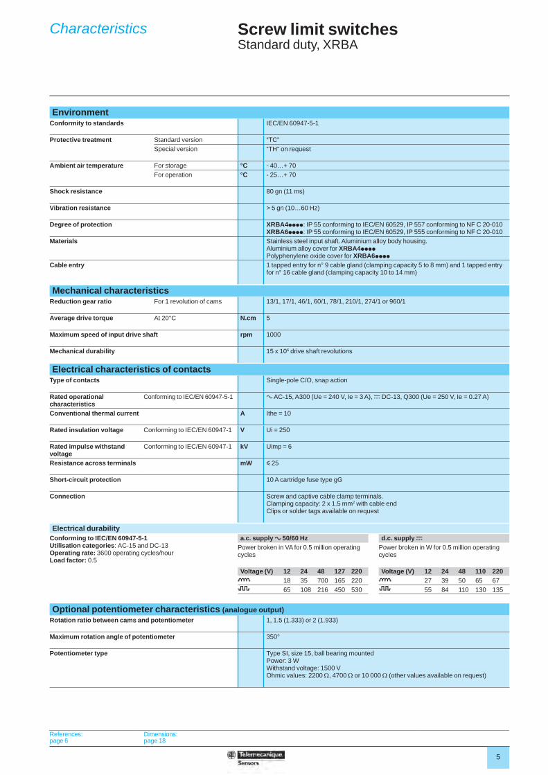
EnvironmentConformity to standards IEC/EN 60947-5-1
Protective treatment Standard version “TC”Special version “TH” on request
Ambient air temperature For storage °C - 40…+ 70 For operation °C - 25…+ 70
Shock resistance 80 gn (11 ms)
Vibration resistance > 5 gn (10…60 Hz)
Degree of protection XRBA4pppp: IP 55 conforming to IEC/EN 60529, IP 557 conforming to NF C 20-010XRBA6pppp: IP 55 conforming to IEC/EN 60529, IP 555 conforming to NF C 20-010
Materials Stainless steel input shaft. Aluminium alloy body housing.Aluminium alloy cover for XRBA4ppppPolyphenylene oxide cover for XRBA6pppp
Cable entry 1 tapped entry for n° 9 cable gland (clamping capacity 5 to 8 mm) and 1 tapped entry for n° 16 cable gland (clamping capacity 10 to 14 mm)
Mechanical characteristicsReduction gear ratio For 1 revolution of cams 13/1, 17/1, 46/1, 60/1, 78/1, 210/1, 274/1 or 960/1
Average drive torque At 20°C N.cm 5
Maximum speed of input drive shaft rpm 1000
Mechanical durability 15 x 106 drive shaft revolutions
Electrical characteristics of contactsType of contacts Single-pole C/O, snap action
Rated operational characteristics
Conforming to IEC/EN 60947-5-1 a AC-15, A300 (Ue = 240 V, Ie = 3 A), c DC-13, Q300 (Ue = 250 V, Ie = 0.27 A)
Conventional thermal current A Ithe = 10
Rated insulation voltage Conforming to IEC/EN 60947-1 V Ui = 250
Rated impulse withstand voltage
Conforming to IEC/EN 60947-1 kV Uimp = 6
Resistance across terminals mW y 25
Short-circuit protection 10 A cartridge fuse type gG
Connection Screw and captive cable clamp terminals. Clamping capacity: 2 x 1.5 mm2 with cable endClips or solder tags available on request
Electrical durabilityConforming to IEC/EN 60947-5-1Utilisation categories: AC-15 and DC-13Operating rate: 3600 operating cycles/hourLoad factor: 0.5
a.c. supply a 50/60 Hz d.c. supply c
Power broken in VA for 0.5 million operating cycles
Power broken in W for 0.5 million operating cycles
Voltage (V) 12 24 48 127 220 Voltage (V) 12 24 48 110 220o 18 35 700 165 220 o 27 39 50 65 678 65 108 216 450 530 8 55 84 110 130 135
Optional potentiometer characteristics (analogue output)Rotation ratio between cams and potentiometer 1, 1.5 (1.333) or 2 (1.933)
Maximum rotation angle of potentiometer 350°
Potentiometer type Type SI, size 15, ball bearing mountedPower: 3 WWithstand voltage: 1500 VOhmic values: 2200 , 4700 or 10 000 (other values available on request)
References:page 6
Dimensions:page 18
Characteristics
6
Screw limit switchesStandard duty, XRBA
Screw limit switchesDescription Number of
contactsBasic reference, to be completed (1)
Weight
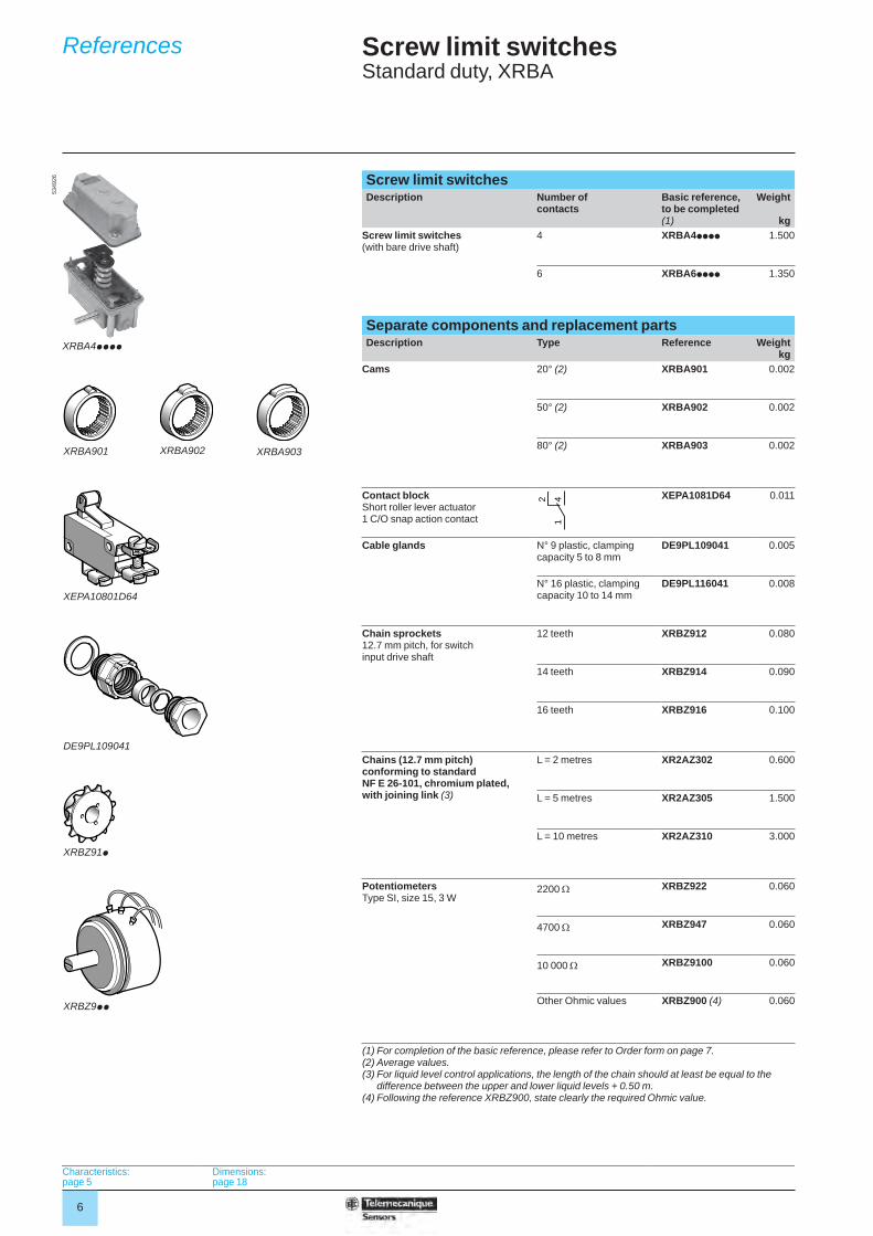
kgScrew limit switches (with bare drive shaft)
4 XRBA4pppp 1.500
6 XRBA6pppp 1.350
Separate components and replacement partsDescription Type Reference Weight
kgCams 20° (2) XRBA901 0.002
50° (2) XRBA902 0.002
80° (2) XRBA903 0.002
Contact blockShort roller lever actuator1 C/O snap action contact
XEPA1081D64 0.011
Cable glands N° 9 plastic, clamping capacity 5 to 8 mm
DE9PL109041 0.005
N° 16 plastic, clamping capacity 10 to 14 mm
DE9PL116041 0.008
Chain sprockets 12.7 mm pitch, for switch input drive shaft
12 teeth XRBZ912 0.080
14 teeth XRBZ914 0.090
16 teeth XRBZ916 0.100
Chains (12.7 mm pitch) conforming to standard NF E 26-101, chromium plated, with joining link (3)
L = 2 metres XR2AZ302 0.600
L = 5 metres XR2AZ305 1.500
L = 10 metres XR2AZ310 3.000
Potentiometers Type SI, size 15, 3 W
2200 XRBZ922 0.060
4700 XRBZ947 0.060
10 000 XRBZ9100 0.060
Other Ohmic values XRBZ900 (4) 0.060
(1) For completion of the basic reference, please refer to Order form on page 7.(2) Average values.(3) For liquid level control applications, the length of the chain should at least be equal to the
difference between the upper and lower liquid levels + 0.50 m.(4) Following the reference XRBZ900, state clearly the required Ohmic value.
XRBA4pppp
5349
26
XRBA901 XRBA902 XRBA903
142
XEPA10801D64
DE9PL109041
XRBZ91p
XRBZ9pp
Characteristics:page 5
Dimensions:page 18
References
7
Screw limit switchesStandard duty, XRBA
Customer Schneider ElectricCompany Order N° Delivery date Sales Offi ce - Subsidiary Co. Order N°
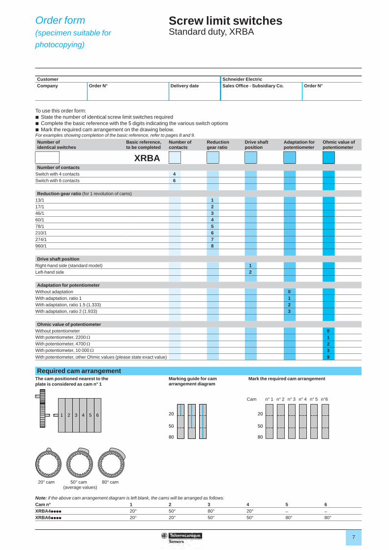
To use this order form:b State the number of identical screw limit switches requiredb Complete the basic reference with the 5 digits indicating the various switch optionsb Mark the required cam arrangement on the drawing below.For examples showing completion of the basic reference, refer to pages 8 and 9.Number of identical switches
Basic reference, to be completed
Number of contacts
Reduction gear ratio
Drive shaft position
Adaptation for potentiometer
Ohmic value of potentiometer
XRBANumber of contacts
Switch with 4 contacts 4Switch with 6 contacts 6
Reduction gear ratio (for 1 revolution of cams)13/1 117/1 246/1 360/1 478/1 5210/1 6274/1 7960/1 8
Drive shaft positionRight-hand side (standard model) 1Left-hand side 2
Adaptation for potentiometerWithout adaptation 0With adaptation, ratio 1 1With adaptation, ratio 1.5 (1.333) 2With adaptation, ratio 2 (1.933) 3
Ohmic value of potentiometerWithout potentiometer 0With potentiometer, 2200 1With potentiometer, 4700 2With potentiometer, 10 000 3With potentiometer, other Ohmic values (please state exact value) 9
Required cam arrangementThe cam positioned nearest to the plate is considered as cam n° 1
Marking guide for cam arrangement diagram
Mark the required cam arrangement
Note: if the above cam arrangement diagram is left blank, the cams will be arranged as follows:Cam n° 1 2 3 4 5 6XRBA4pppp 20° 50° 80° 20° _ _
XRBA6pppp 20° 20° 50° 50° 80° 80°
1 6542 3 20
50
80
20
50
80
Cam n° 1 n° 2 n° 3 n° 4 n° 5 n°6
20° cam 50° cam 80° cam(average values)
Order form(specimen suitable for photocopying)
8
Screw limit switchesStandard duty, XRBA
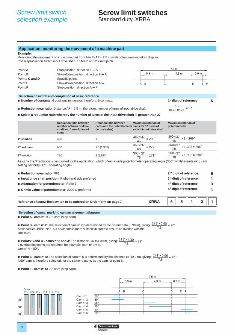
Application: monitoring the movement of a machine partExample:Monitoring the movement of a machine part from A to F (AF = 7.5 m) with potentiometer linked display.Chain sprocket on switch input drive shaft: 16 teeth on 12.7 mm pitch.
Point A Stop position, direction F V APoint B Slow-down position, direction F V APoints C and D Specifi c pointsPoint E Slow-down position, direction A V FPoint F Stop position, direction A V F
Selection of switch and completion of basic referenceb Number of contacts: 6 positions to monitor, therefore, 6 contacts. 1st digit of reference: 6
b Reduction gear ratio: Distance AF = 7.5 m, therefore, number of turns of input drive shaft:
b Select a reduction ratio whereby the number of turns of the input drive shaft is greater than 37
Reduction ratio between number of turns of drive shaft and 1 revolution of cams
Rotation ratio between cams and the potentiometer (actual value)
Maximum rotation of cams for 37 turns of switch input drive shaft
Maximum rotation of potentiometer
1st solution 46/1 1
2nd solution 60/1 1.5 (1,333)
3rd solution 78/1 2 (1.933)
Assume the 3rd solution is best suited for the application, which offers a wide potentiometer operating angle (330°) whilst maintaining cam setting fl exibility (171° operating angle).
b Reduction gear ratio: 78/1 2nd digit of reference: 5b Input drive shaft position: Right-hand side preferred 3rd digit of reference: 1b Adaptation for potentiometer: Ratio 2 4th digit of reference: 3b Ohmic value of potentiometer: 2200 preferred 5th digit of reference: 1
Reference of screw limit switch to be entered on Order form on page 7 XRBA 6 5 1 3 1
Selection of cams, marking cam arrangement diagramb Point A - cam n° 1: 20° cam (stop cam).
b Point B - cam n° 2: The selection of cam n° 2 is determined by the distance BA (0.90 m), giving: A 20° cam could be used, but a 50° cam is more suitable in order to ensure an overlap with the stop cam.
b Points C and D - cams n° 3 and 4: The distance CD = 4.30 m, giving: 2 overlapping cams are required, for example: cam n° 3 = 50°, cam n° 4 = 80°.
b Point E - cam n° 5: The selection of cam n° 5 is determined by the distance EF (0.9 m), giving: A 50° cam is therefore selected, for the same reasons as the cam for point B.
b Point F - cam n° 6: 20° cam (stop cam).
A B C D E F
0,9 m 0,9 m4,3 m
7,5 m
A B C D E F
0,9 m 0,9 m4,3 m
7,5 m
20˚
50˚
80˚
Cam n° 1 20°Cam n° 2 50°Cam n° 3 50°Cam n° 4 80°Cam n° 5 50°Cam n° 6 20°
Camsn° 1 n° 2 n° 3 n° 4 n° 5 n° 6
Screw limit switch selection example
7.516×0.0127 = 37
360×37 46 = 289°
360×37 60 = 222°
360×37 78 = 171°
360×37 46 ×1= 269°
360×37 60 ×1.333 = 296°
360×37 78 ×1.933 = 330°
171°×0.90 7.5 ≈ 20°
171°×4.30 7.5 ≈ 98°
171°×0.90 7.5 ≈ 20°
9
Screw limit switchesStandard duty, XRBA
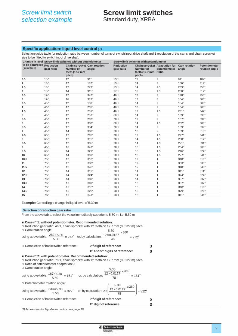
Specifi c application: liquid level control (1)Selection guide table for reduction ratio between number of turns of switch input drive shaft and 1 revolution of the cams and chain sprocket size to be fi tted to switch input drive shaft.Change in level to be controlled (in metres)
Screw limit switches without potentiometer Screw limit switches with potentiometerReduction gear ratio
Chain sprocket Number of teeth (12.7 mm pitch)
Cam rotation angle
Reduction gear ratio
Chain sprocket Number of teeth (12.7 mm pitch)
Adaptation for potentiometer Ratio
Cam rotation angle
Potentiometer rotation angle
0.5 13/1 12 91° 13/1 12 2 91° 182°1 13/1 12 182° 13/1 14 2 156° 312°1.5 13/1 12 273° 13/1 14 1.5 233° 350°2 13/1 14 311° 17/1 16 1.5 208° 312°2.5 17/1 12 347° 46/1 12 2 128° 256°3 17/1 16 313° 46/1 12 2 154° 308°3.5 46/1 12 180° 46/1 14 2 154° 308°4 46/1 12 205° 46/1 16 2 154° 308°4.5 46/1 12 231° 46/1 12 1.5 231° 347°5 46/1 12 257° 60/1 14 2 169° 338°5.5 46/1 12 282° 78/1 12 2 167° 334°6 46/1 12 308° 60/1 14 1.5 202° 303°6.5 46/1 12 334° 78/1 14 2 169° 339°7 46/1 14 308° 78/1 16 2 159° 318°7.5 60/1 12 295° 78/1 12 1.5 227° 341°8 60/1 12 315° 78/1 14 1.5 208° 312°8.5 60/1 12 335° 78/1 14 1.5 221° 331°9 46/1 16 347° 78/1 16 1.5 204° 306°9.5 60/1 14 321° 78/1 16 1.5 216° 324°10 60/1 14 337° 78/1 16 1.5 227° 341°10.5 78/1 12 318° 78/1 12 1 318° 318°11 78/1 12 333° 78/1 12 1 333° 333°11.5 78/1 12 348° 78/1 12 1 348° 348°12 78/1 14 311° 78/1 14 1 311° 311°12.5 78/1 14 324° 78/1 14 1 324° 324°13 78/1 14 337° 78/1 14 1 337° 337°13.5 78/1 16 307° 78/1 16 1 307° 307°14 78/1 16 318° 78/1 16 1 318° 318°14.5 78/1 16 329° 78/1 16 1 329° 329°15 78/1 16 341° 78/1 16 1 341° 341°
Example: Controlling a change in liquid level of 5.30 m
Selection of reduction gear ratioFrom the above table, select the value immediately superior to 5.30 m, i.e. 5.50 m
b Case n° 1: without potentiometer. Recommended solution:v Reduction gear ratio: 46/1, chain sprocket with 12 teeth on 12.7 mm (0.0127 m) pitch.v Cam rotation angle:
using above table: or, by calculation:
v Completion of basic switch reference: 2nd digit of reference: 34th and 5th digits of reference: 0
b Case n° 2: with potentiometer. Recommended solution:v Reduction gear ratio: 78/1, chain sprocket with 12 teeth on 12.7 mm (0.0127 m) pitch.v Ratio of potentiometer adaptation: 2v Cam rotation angle:
using above table: or, by calculation:
v Potentiometer rotation angle:
using above table: or, by calculation:
v Completion of basic switch reference: 2nd digit of reference: 54th digit of reference: 3
(1) Accessories for liquid level control: see page 16.
Screw limit switch selection example
= 272°282×5.30 5.50 = 272°
5.3012×0.0127
×360
46
= 161°
5.3012×0.0127
×360
78= 161°167×5.30 5.50
= 322°334×5.30 5.50 = 322°
5.3012×0.0127
×360
782×
10
Screw limit switchesHeavy duty, XR2
Functions
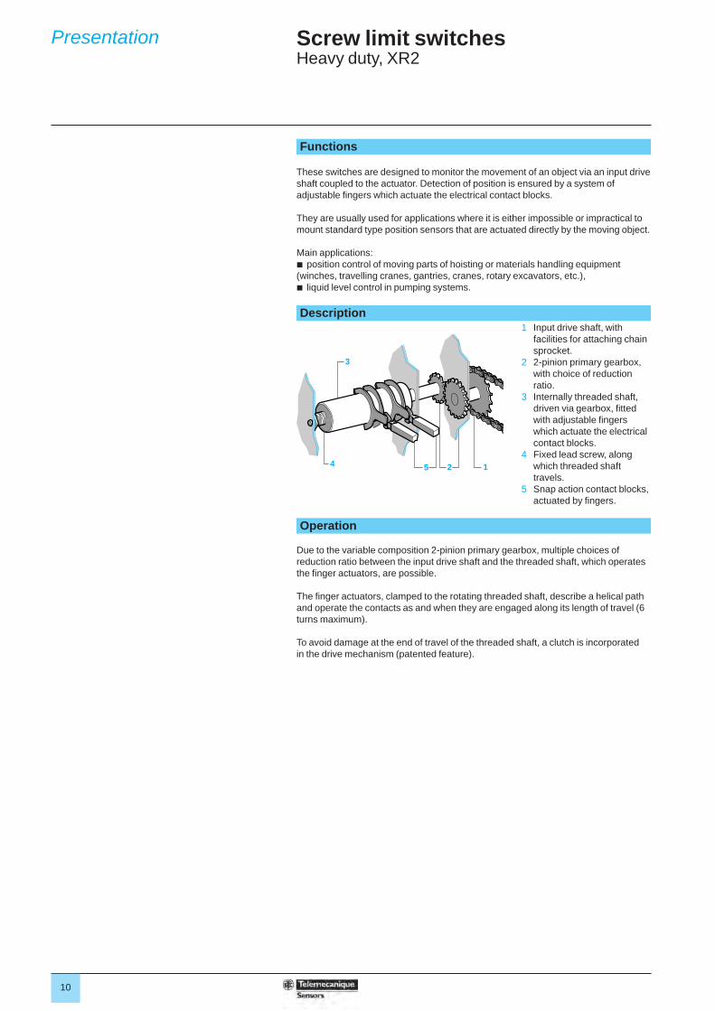
These switches are designed to monitor the movement of an object via an input drive shaft coupled to the actuator. Detection of position is ensured by a system of adjustable fi ngers which actuate the electrical contact blocks.
They are usually used for applications where it is either impossible or impractical to mount standard type position sensors that are actuated directly by the moving object.
Main applications:b position control of moving parts of hoisting or materials handling equipment (winches, travelling cranes, gantries, cranes, rotary excavators, etc.),b liquid level control in pumping systems. Description
1 Input drive shaft, with facilities for attaching chain sprocket.
2 2-pinion primary gearbox, with choice of reduction ratio.
3 Internally threaded shaft, driven via gearbox, fi tted with adjustable fi ngers which actuate the electrical contact blocks.
4 Fixed lead screw, along which threaded shaft travels.
5 Snap action contact blocks, actuated by fi ngers.
Operation
Due to the variable composition 2-pinion primary gearbox, multiple choices of reduction ratio between the input drive shaft and the threaded shaft, which operates the fi nger actuators, are possible.
The fi nger actuators, clamped to the rotating threaded shaft, describe a helical path and operate the contacts as and when they are engaged along its length of travel (6 turns maximum).
To avoid damage at the end of travel of the threaded shaft, a clutch is incorporated in the drive mechanism (patented feature).
12
3
4 5
Presentation
11
Screw limit switchesHeavy duty, XR2
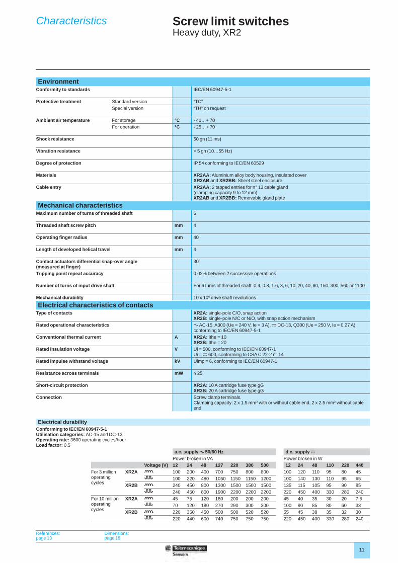
EnvironmentConformity to standards IEC/EN 60947-5-1
Protective treatment Standard version “TC”Special version “TH” on request
Ambient air temperature For storage °C - 40…+ 70For operation °C - 25…+ 70
Shock resistance 50 gn (11 ms)
Vibration resistance > 5 gn (10…55 Hz)
Degree of protection IP 54 conforming to IEC/EN 60529
Materials XR2AA: Aluminium alloy body housing, insulated coverXR2AB and XR2BB: Sheet steel enclosure
Cable entry XR2AA: 2 tapped entries for n° 13 cable gland(clamping capacity 9 to 12 mm)XR2AB and XR2BB: Removable gland plate
Mechanical characteristicsMaximum number of turns of threaded shaft 6
Threaded shaft screw pitch mm 4
Operating fi nger radius mm 40
Length of developed helical travel mm 4
Contact actuators differential snap-over angle (measured at fi nger)
30°
Tripping point repeat accuracy 0.02% between 2 successive operations
Number of turns of input drive shaft For 6 turns of threaded shaft: 0.4, 0.8, 1.6, 3, 6, 10, 20, 40, 80, 150, 300, 560 or 1100
Mechanical durability 10 x 106 drive shaft revolutions
Electrical characteristics of contactsType of contacts XR2A: single-pole C/O, snap action
XR2B: single-pole N/C or N/O, with snap action mechanismRated operational characteristics a AC-15, A300 (Ue = 240 V, Ie = 3 A), c DC-13, Q300 (Ue = 250 V, Ie = 0.27 A),
conforming to IEC/EN 60947-5-1Conventional thermal current A XR2A: Ithe = 10
XR2B: Ithe = 20Rated insulation voltage V Ui = 500, conforming to IEC/EN 60947-1
Ui = c 600, conforming to CSA C 22-2 n° 14Rated impulse withstand voltage kV Uimp = 6, conforming to IEC/EN 60947-1
Resistance across terminals mW y 25
Short-circuit protection XR2A: 10 A cartridge fuse type gGXR2B: 20 A cartridge fuse type gG
Connection Screw clamp terminals. Clamping capacity: 2 x 1.5 mm2 with or without cable end, 2 x 2.5 mm2 without cable end
Electrical durabilityConforming to IEC/EN 60947-5-1Utilisation categories: AC-15 and DC-13Operating rate: 3600 operating cycles/hourLoad factor: 0.5
a.c. supply a 50/60 Hz d.c. supply cPower broken in VA Power broken in W
Voltage (V) 12 24 48 127 220 380 500 12 24 48 110 220 440For 3 million operating cycles
XR2A o 100 200 400 700 750 800 800 100 120 110 95 80 458 100 220 480 1050 1150 1150 1200 100 140 130 110 95 65
XR2B o 240 450 800 1300 1500 1500 1500 135 115 105 95 90 858 240 450 800 1900 2200 2200 2200 220 450 400 330 280 240
For 10 million operating cycles
XR2A o 45 75 120 180 200 200 200 45 40 35 30 20 7.58 70 120 180 270 290 300 300 100 90 85 80 60 33
XR2B o 220 350 450 500 500 520 520 55 45 38 35 32 308 220 440 600 740 750 750 750 220 450 400 330 280 240
References:page 13
Dimensions:page 18
Characteristics
12
Screw limit switchesHeavy duty, XR2
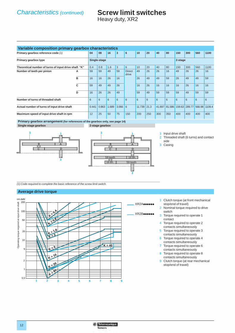
Variable composition primary gearbox characteristicsPrimary gearbox reference code (1) 04 08 16 3 6 10 20 40 80 150 300 560 1100
Primary gearbox type Single-stage 2-stage
Theoretical number of turns of input drive shaft “K” 0.4 0.8 1.6 3 6 10 20 40 80 150 300 560 1100Number of teeth per pinion A 59 59 49 59 Direct
drive49 26 26 16 49 26 26 16
B 16 16 26 16 26 49 49 59 26 49 49 59
C 59 49 49 26 16 26 16 16 16 26 16 16
D 16 26 26 49 59 49 59 59 59 49 59 59
Number of turns of threaded shaft 6 6 6 6 6 6 6 6 6 6 6 6 6
Actual number of turns of input drive shaft 0.441 0.863 1.689 3.066 6 11.739 21.3 41.697 81.586 159.63 289.77 566.98 1109.4
Maximum speed of input drive shaft in rpm 12 25 50 75 150 200 250 300 350 400 400 400 400
Primary gearbox arrangement (for references of the gearbox only, see page 14)Single-stage gearbox 2-stage gearbox
1 Input drive shaft2 Threaded shaft (6 turns) and contact
side3 Casing
(1) Code required to complete the basic reference of the screw limit switch.
Average drive torque
XR2Apppppp
XR2Bpppppp
1 Clutch torque (at front mechanical stop/end of travel)
2 Nominal torque required to drive switch
3 Torque required to operate 1 contact
4 Torque required to operate 2 contacts simultaneously
5 Torque required to operate 3 contacts simultaneously
6 Torque required to operate 4 contacts simultaneously
7 Torque required to operate 6 contacts simultaneously
8 Torque required to operate 8 contacts simultaneously
9 Clutch torque (at rear mechanical stop/end of travel)
AB
DC
1
2
3
AB
DC
1
2
3
16 tth.
16 tth. 59 teeth
59 teeth
N = 10
K = 3
200cm.daN
100
50
20
10
5
2
1
0,51 2 3 4 5 6 7 8 9
K = 40
K = 0,8
K = 10
K = 20
K = 80
K = 1,6
K = 3
K = 6
K = 0,4
Ope
ratin
g to
rque
requ
ired
at in
put d
rive
shaf
t
Characteristics (continued)
13
Screw limit switchesHeavy duty, XR2
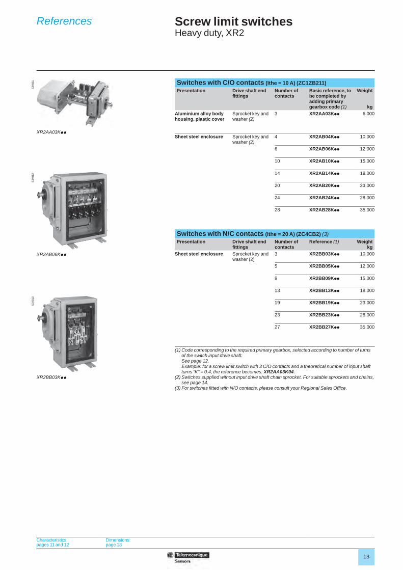
Switches with C/O contacts (Ithe = 10 A) (ZC1ZB211)Presentation Drive shaft end
fi ttingsNumber of contacts
Basic reference, to be completed by adding primary gearbox code (1)
Weight
kgAluminium alloy body housing, plastic cover
Sprocket key and washer (2)
3 XR2AA03Kpp 6.000
Sheet steel enclosure Sprocket key and washer (2)
4 XR2AB04Kpp 10.000
6 XR2AB06Kpp 12.000
10 XR2AB10Kpp 15.000
14 XR2AB14Kpp 18.000
20 XR2AB20Kpp 23.000
24 XR2AB24Kpp 28.000
28 XR2AB28Kpp 35.000
Switches with N/C contacts (Ithe = 20 A) (ZC4CB2) (3)Presentation Drive shaft end
fi ttingsNumber of contacts
Reference (1) Weightkg
Sheet steel enclosure Sprocket key and washer (2)
3 XR2BB03Kpp 10.000
5 XR2BB05Kpp 12.000
9 XR2BB09Kpp 15.000
13 XR2BB13Kpp 18.000
19 XR2BB19Kpp 23.000
23 XR2BB23Kpp 28.000
27 XR2BB27Kpp 35.000
(1) Code corresponding to the required primary gearbox, selected according to number of turns of the switch input drive shaft. See page 12.Example: for a screw limit switch with 3 C/O contacts and a theoretical number of input shaft turns “K” = 0.4, the reference becomes: XR2AA03K04.
(2) Switches supplied without input drive shaft chain sprocket. For suitable sprockets and chains, see page 14.
(3) For switches fi tted with N/O contacts, please consult your Regional Sales Offi ce.
XR2AA03Kpp
5349
11
XR2AB06Kpp
5349
12
XR2BB03Kpp
5349
13
Characteristics:pages 11 and 12
Dimensions:page 18
References
14
Screw limit switchesHeavy duty, XR2
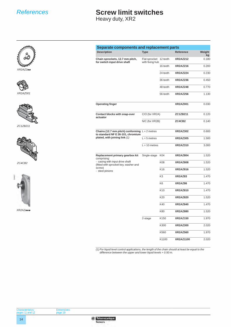
Separate components and replacement partsDescription Type Reference Weight
kgChain sprockets, 12.7 mm pitch, for switch input drive shaft
Flat sprocket with fi xing hub
12 teeth XR2AZ212 0.180
16 teeth XR2AZ216 0.200
24 teeth XR2AZ224 0.230
36 teeth XR2AZ236 0.450
48 teeth XR2AZ248 0.770
56 teeth XR2AZ256 1.130
Operating fi nger XR2AZ001 0.030
Contact blocks with snap-over actuator
C/O (for XR2A) ZC1ZB211 0.120
N/C (for XR2B) ZC4CB2 0.140
Chains (12.7 mm pitch) conforming to standard NF E 26-101, chromium plated, with joining link (1)
L = 2 metres XR2AZ302 0.600
L = 5 metres XR2AZ305 1.500
L = 10 metres XR2AZ310 3.000
Replacement primary gearbox kitcomprising:- casing with input drive shaft (fi tted with sprocket key, washer and screw)- steel pinions
Single-stage K04 XR2AZ804 1.520
K08 XR2AZ808 1.520
K16 XR2AZ816 1.520
K3 XR2AZ83 1.470
K6 XR2AZ86 1.470
K10 XR2AZ810 1.470
K20 XR2AZ820 1.520
K40 XR2AZ840 1.470
K80 XR2AZ880 1.520
2-stage K150 XR2AZ150 1.970
K300 XR2AZ300 2.020
K560 XR2AZ560 1.970
K1100 XR2AZ1100 2.020
(1) For liquid level control applications, the length of the chain should at least be equal to the difference between the upper and lower liquid levels + 0.50 m.
XR2AZ2pp
XR2AZ001
ZC1ZB211
ZC4CB2
XR2AZppp
5349
27
Characteristics:pages 11 and 12
Dimensions:page 19
References
15
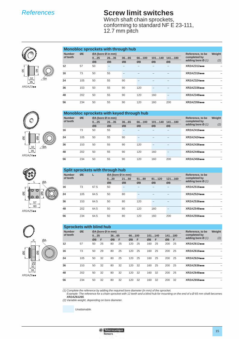
Screw limit switchesWinch shaft chain sprockets, conforming to standard NF E 23-111, 12.7 mm pitch
Monobloc sprockets with through hubNumber of teeth
ØE ØA (bore Ø in mm) Reference, to be completed by adding bore Ø (1)
Weight
(2)0…25 26…35 36…65 66…100 101…140 141…180ØB ØB ØB ØB ØB ØB
12 57 50 – – – – – XR2AZ312ppp –
16 73 50 55 – – – – XR2AZ316ppp –
24 105 50 55 90 – – – XR2AZ324ppp –
36 153 50 55 90 120 – – XR2AZ336ppp –
48 202 50 55 90 120 160 – XR2AZ348ppp –
56 234 50 55 90 120 160 200 XR2AZ356ppp –
Monobloc sprockets with keyed through hubNumber of teeth
ØE ØA (bore Ø in mm) Reference, to be completed by adding bore Ø (1)
Weight
(2)0…25 26…35 36…65 66…100 101…140 141…180ØB ØB ØB ØB ØB ØB
16 73 50 55 – – – – XR2AZ416ppp –
24 105 50 55 90 – – – XR2AZ424ppp –
36 153 50 55 90 120 – – XR2AZ436ppp –
48 202 50 55 90 120 160 – XR2AZ448ppp –
56 234 50 55 90 120 160 200 XR2AZ456ppp –
Split sprockets with through hubNumber of teeth
ØE L ØA (bore Ø in mm) Reference, to be completed by adding bore Ø (1)
0…20 21…50 51…80 81…120 121…160ØB ØB ØB ØB ØB
16 73 67.5 50 – – – – XR2AZ516ppp –
24 105 64.5 50 80 – – – XR2AZ524ppp –
36 153 64.5 50 80 120 – – XR2AZ536ppp –
48 202 64.5 50 80 120 160 – XR2AZ548ppp –
56 234 64.5 50 80 120 160 200 XR2AZ556ppp –
Sprockets with blind hubNumber of teeth
ØE ØA (bore Ø in mm) Reference, to be completed by adding bore Ø (1)
Weight
(2)0…35 36…65 66…100 101…140 141…180ØB F ØB F ØB F ØB F ØB F
12 57 50 25 80 25 120 25 160 25 200 25 XR2AZ612ppp –
16 73 50 29 80 25 120 25 160 25 200 25 XR2AZ616ppp –
24 105 50 32 80 25 120 25 160 25 200 25 XR2AZ624ppp –
36 153 50 32 80 32 120 32 160 25 200 25 XR2AZ636ppp –
48 202 50 32 80 32 120 32 160 32 200 25 XR2AZ648ppp –
56 234 50 32 80 32 120 32 160 32 200 32 XR2AZ656ppp –
(1) Complete the reference by adding the required bore diameter (in mm) of the sprocket.Example: The reference for a chain sprocket with 12 teeth and a blind hub for mounting on the end of a Ø 65 mm shaft becomes XR2AZ61265.
(2) Variable weight, depending on bore diameter.
Unattainable.
3235
XR2AZ3pp
ØA3235
ØE
ØB
XR2AZ4pp
ØA
5760
L
ØE
ØB
XR2AZ5pp
ØB
3220
35
F
ØE
ØA
XR2AZ6pp
References
16
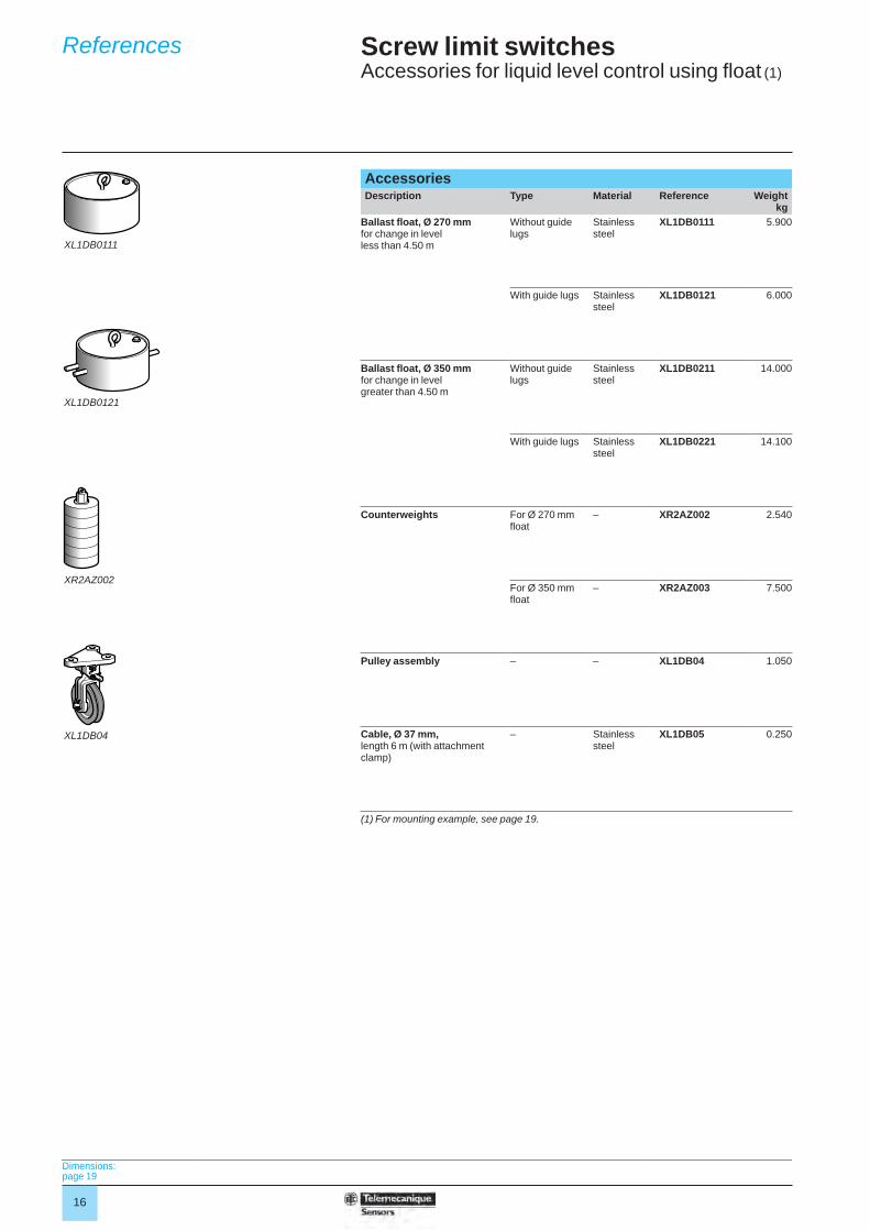
Screw limit switchesAccessories for liquid level control using fl oat (1)
Accessories Description Type Material Reference Weight
kgBallast fl oat, Ø 270 mm for change in level less than 4.50 m
Without guide lugs
Stainless steel
XL1DB0111 5.900
With guide lugs Stainless steel
XL1DB0121 6.000
Ballast fl oat, Ø 350 mm for change in level greater than 4.50 m
Without guide lugs
Stainless steel
XL1DB0211 14.000
With guide lugs Stainless steel
XL1DB0221 14.100
Counterweights For Ø 270 mm fl oat
– XR2AZ002 2.540
For Ø 350 mm fl oat
– XR2AZ003 7.500
Pulley assembly – – XL1DB04 1.050
Cable, Ø 37 mm, length 6 m (with attachment clamp)
– Stainless steel
XL1DB05 0.250
(1) For mounting example, see page 19.
XL1DB0111
XL1DB0121
XR2AZ002
XL1DB04
Dimensions:page 19
References
17
Screw limit switchesDifferential drive units
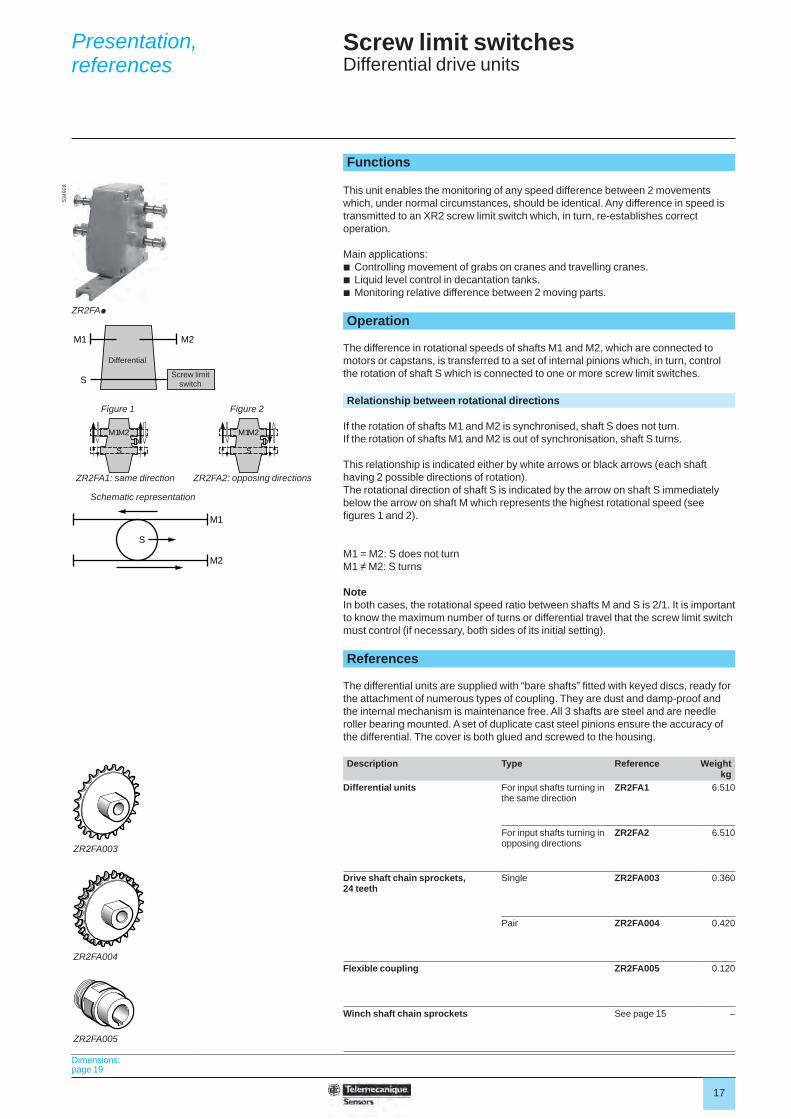
Functions
This unit enables the monitoring of any speed difference between 2 movements which, under normal circumstances, should be identical. Any difference in speed is transmitted to an XR2 screw limit switch which, in turn, re-establishes correct operation.
Main applications:b Controlling movement of grabs on cranes and travelling cranes.b Liquid level control in decantation tanks.b Monitoring relative difference between 2 moving parts. Operation
The difference in rotational speeds of shafts M1 and M2, which are connected to motors or capstans, is transferred to a set of internal pinions which, in turn, control the rotation of shaft S which is connected to one or more screw limit switches. Relationship between rotational directions
If the rotation of shafts M1 and M2 is synchronised, shaft S does not turn.If the rotation of shafts M1 and M2 is out of synchronisation, shaft S turns.
This relationship is indicated either by white arrows or black arrows (each shaft having 2 possible directions of rotation).The rotational direction of shaft S is indicated by the arrow on shaft S immediately below the arrow on shaft M which represents the highest rotational speed (see fi gures 1 and 2).
M1 = M2: S does not turnM1 ≠ M2: S turns
NoteIn both cases, the rotational speed ratio between shafts M and S is 2/1. It is important to know the maximum number of turns or differential travel that the screw limit switch must control (if necessary, both sides of its initial setting). References
The differential units are supplied with “bare shafts” fi tted with keyed discs, ready for the attachment of numerous types of coupling. They are dust and damp-proof and the internal mechanism is maintenance free. All 3 shafts are steel and are needle roller bearing mounted. A set of duplicate cast steel pinions ensure the accuracy of the differential. The cover is both glued and screwed to the housing. Description Type Reference Weight
kgDifferential units For input shafts turning in
the same directionZR2FA1 6.510
For input shafts turning in opposing directions
ZR2FA2 6.510
Drive shaft chain sprockets, 24 teeth
Single ZR2FA003 0.360
Pair ZR2FA004 0.420
Flexible coupling ZR2FA005 0.120
Winch shaft chain sprockets See page 15 –
ZR2FAp
5349
28
S
M1
M2
S
M1 M2
M1M2 M1
S S
M2
Figure 1
Differential
Screw limit switch
Figure 2
ZR2FA1: same direction ZR2FA2: opposing directions
Schematic representation
ZR2FA003
ZR2FA004
ZR2FA005
Dimensions:page 19
Presentation, references
18
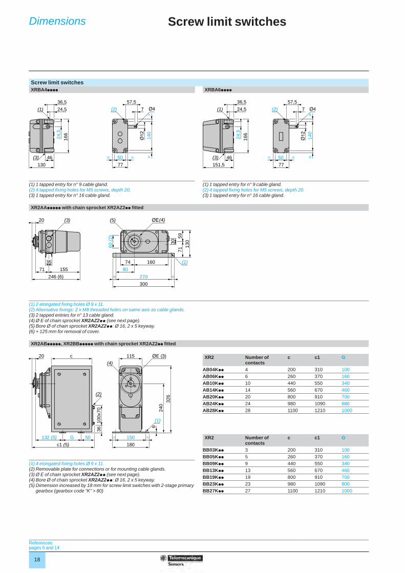
Screw limit switches
Screw limit switchesXRBA4pppp XRBA6pppp
(1) 1 tapped entry for n° 9 cable gland.(2) 4 tapped fi xing holes for M5 screws, depth 20.(3) 1 tapped entry for n° 16 cable gland.
(1) 1 tapped entry for n° 9 cable gland.(2) 4 tapped fi xing holes for M5 screws, depth 20.(3) 1 tapped entry for n° 16 cable gland.
XR2AAppppp with chain sprocket XR2AZ2pp fi tted
(1) 2 elongated fi xing holes Ø 9 x 11.(2) Alternative fi xings: 2 x M8 threaded holes on same axis as cable glands.(3) 2 tapped entries for n° 13 cable gland.(4) Ø E of chain sprocket XR2AZ2pp (see next page).(5) Bore Ø of chain sprocket XR2AZ2pp: Ø 16, 2 x 5 keyway.(6) + 125 mm for removal of cover.
XR2ABppppp, XR2BBppppp with chain sprocket XR2AZ2pp fi tted
XR2 Number of contacts
c c1 G
AB04Kpp 4 200 310 100AB06Kpp 6 260 370 160AB10Kpp 10 440 550 340AB14Kpp 14 560 670 460AB20Kpp 20 800 910 700AB24Kpp 24 980 1090 880AB28Kpp 28 1100 1210 1000
XR2 Number of contacts
c c1 G
BB03Kpp 3 200 310 100BB05Kpp 5 260 370 160
(1) 4 elongated fi xing holes Ø 9 x 11.(2) Removable plate for connections or for mounting cable glands.(3) Ø E of chain sprocket XR2AZ2pp (see next page).(4) Bore Ø of chain sprocket XR2AZ2pp: Ø 16, 2 x 5 keyway.(5) Dimension increased by 18 mm for screw limit switches with 2-stage primary
gearbox (gearbox code “K” > 80)
BB09Kpp 9 440 550 340BB13Kpp 13 560 670 460BB19Kpp 19 800 910 700BB23Kpp 23 980 1090 800BB27Kpp 27 1100 1210 1000
50= =
77
(2) 7
57,5
140
==
46
130
(3)
24,5
166
(1) 24,5
36,5
46
151,5
(3)
(1)
24,5
166
24,5
36,5
50= =
77
(2) 7
57,5
140
==
35
71 155
246 (6)
20 (3)
74
90
160
270 ==
300
(5) (4)
(1)
30
59
130
71
60 (
2)
(2)
50
c1 (5)
G132 (5)
c20
3610
0x70
326
(1)
(4)
115
180
150= =
6
240
References:pages 6 and 14
Dimensions
19
Screw limit switches
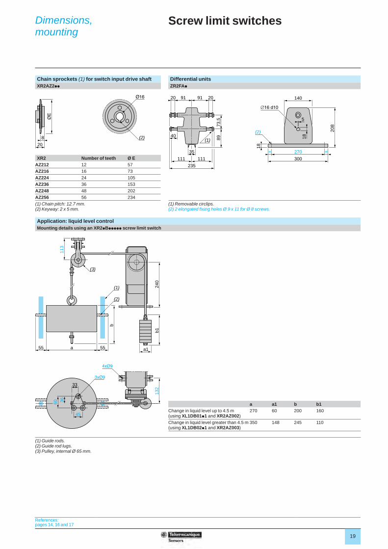
Chain sprockets (1) for switch input drive shaft Differential unitsXR2AZ2pp ZR2FAp
XR2 Number of teeth Ø EAZ212 12 57AZ216 16 73AZ224 24 105AZ236 36 153AZ248 48 202AZ256 56 234(1) Chain pitch: 12.7 mm.(2) Keyway: 2 x 5 mm.
(1) Removable circlips.(2) 2 elongated fi xing holes Ø 9 x 11 for Ø 8 screws.
Application: liquid level controlMounting details using an XR2pBppppp screw limit switch
a a1 b b1Change in liquid level up to 4.5 m (using XL1DB01p1 and XR2AZ002)
270 60 200 160
Change in liquid level greater than 4.5 m (using XL1DB02p1 and XR2AZ003)
350 148 245 110
(1) Guide rods.(2) Guide rod lugs.(3) Pulley, internal Ø 65 mm.
8
20
(2)
5
270= =
300
140
(2)
18
18
208
35
40
91 209120
111
235
111
(1)
73,5
89
33
45
132
3660
a15555 a
(2)
(1)
(3)
240
b
b1
113
References:pages 14, 16 and 17
Dimensions, mounting

The information provided in this documentation contains general descriptions and/or technical characteristics of the performance of the products contained herein. This documentation is not intended as a substitute for and is not to be used for determining suitability or reliability of these products for specifi c user applications. It is the duty of any such user or integrator to perform the appropriate and complete risk analysis, evaluation and testing of the products with respect to the relevant specifi c application or use thereof. Neither Schneider Electric nor any of its affi liates or subsidiaries shall be responsible or liable for misuse of the information contained herein.
Design: Schneider ElectricPhotos: Schneider Electric
Head Offi ce35, rue Joseph MonierF-92500 Rueil-MalmaisonFrance
Schneider Electric Industries SAS www.tesensors.com


