Download - SBS Hardware
Information
Base Station System
Technical Description (TED:BSS)BS-240/241
A30808-X3247-K14-4-7618
2 A30808-X3247-K14-4-7618
Technical Description (TED:BSS)BS-240/241
InformationBase Station System
! Important Notice on Product Safety
DANGER - RISK OF ELECTRICAL SHOCK OR DEATH - FOLLOW ALL INSTALLATION INSTRUCTIONS.
The system complies with the standard EN 60950 / IEC 60950. All equipment connected to the system mustcomply with the applicable safety standards.Hazardous voltages are present at the AC power supply lines in this electrical equipment. Some components mayalso have high operating temperatures.Failure to observe and follow all installation and safety instructions can result in serious personal injuryor property damage.Therefore, only trained and qualified personnel may install and maintain the system.
The same text in German:
Wichtiger Hinweis zur Produktsicherheit
LEBENSGEFAHR - BEACHTEN SIE ALLE INSTALLATIONSHINWEISE.
Das System entspricht den Anforderungen der EN 60950 / IEC 60950. Alle an das System angeschlossenenGeräte müssen die zutreffenden Sicherheitsbestimmungen erfüllen.In diesen Anlagen stehen die Netzversorgungsleitungen unter gefährlicher Spannung. Einige Komponentenkönnen auch eine hohe Betriebstemperatur aufweisen.Nichtbeachtung der Installations- und Sicherheitshinweise kann zu schweren Körperverletzungen oderSachschäden führen.Deshalb darf nur geschultes und qualifiziertes Personal das System installieren und warten.
Caution:This equipment has been tested and found to comply with EN 301489. Its class of conformity is defined in tableA30808-X3247-X910-*-7618, which is shipped with each product. This class also corresponds to the limits for aClass A digital device, pursuant to part 15 of the FCC Rules.These limits are designed to provide reasonable protection against harmful interference when the equipment isoperated in a commercial environment.This equipment generates, uses and can radiate radio frequency energy and, if not installed and used in accor-dance with the relevant standards referenced in the manual “Guide to Documentation”, may cause harmful inter-ference to radio communications.For system installations it is strictly required to choose all installation sites according to national and local require-ments concerning construction rules and static load capacities of buildings and roofs.For all sites, in particular in residential areas it is mandatory to observe all respectively applicable electromagneticfield / force (EMF) limits. Otherwise harmful personal interference is possible.
Trademarks:
All designations used in this document can be trademarks, the use of which by third parties for their own purposescould violate the rights of their owners.
Copyright (C) Siemens AG 2003.
Issued by the Information and Communication Mobile GroupHofmannstraße 51D-81359 München
Technical modifications possible.Technical specifications and features are binding only insofar asthey are specifically and expressly agreed upon in a written contract.
A30808-X3247-K14-4-7618 3
InformationBase Station System
Technical Description (TED:BSS)BS-240/241
Reason for UpdateSummary:
Fourth Edition for Release BR6.0
Details:
Chapter/Section Reason for Update
General corrections and improvements in all Chap-
ters/Sections
Issue HistoryIssue
Number
Date of issue Reason for Update
1 06/2002 First Edition for new Release BR6.0
2 09/2002 Second Edition for Release BR6.0
3 11/2002 Third Edition for Release BR6.0
4 05/2003 Fourth Edition for Release BR6.0
4 A30808-X3247-K14-4-7618
Technical Description (TED:BSS)BS-240/241
InformationBase Station System
A30808-X3247-K14-4-7618 5
InformationBase Station System
Technical Description (TED:BSS)BS-240/241
This document consists of a total of 65 pages. All pages are issue 4.
Contents
1 Introduction . . . . . . . . . . . . . . . . . . . . . . . . . . . . . . . . . . . . . . . . . . . . . . . . . . 91.1 Main Features . . . . . . . . . . . . . . . . . . . . . . . . . . . . . . . . . . . . . . . . . . . . . . . 101.2 Technical Data . . . . . . . . . . . . . . . . . . . . . . . . . . . . . . . . . . . . . . . . . . . . . . 12
2 Hardware Architecture . . . . . . . . . . . . . . . . . . . . . . . . . . . . . . . . . . . . . . . . 142.1 Board Redundancy . . . . . . . . . . . . . . . . . . . . . . . . . . . . . . . . . . . . . . . . . . . 172.1.1 AC/DC. . . . . . . . . . . . . . . . . . . . . . . . . . . . . . . . . . . . . . . . . . . . . . . . . . . . . 172.1.2 Core . . . . . . . . . . . . . . . . . . . . . . . . . . . . . . . . . . . . . . . . . . . . . . . . . . . . . . 172.2 Power Amplifier Output Level (typical values) . . . . . . . . . . . . . . . . . . . . . . 182.3 Rack Configuration . . . . . . . . . . . . . . . . . . . . . . . . . . . . . . . . . . . . . . . . . . . 20
3 Description of Modules . . . . . . . . . . . . . . . . . . . . . . . . . . . . . . . . . . . . . . . . 253.1 Core (COBA and COSA) . . . . . . . . . . . . . . . . . . . . . . . . . . . . . . . . . . . . . . 263.1.1 Core Basis (COBA2P8) . . . . . . . . . . . . . . . . . . . . . . . . . . . . . . . . . . . . . . . 273.1.2 Core Satellite (COSA6P16) . . . . . . . . . . . . . . . . . . . . . . . . . . . . . . . . . . . . 293.2 Carrier Unit (CU) . . . . . . . . . . . . . . . . . . . . . . . . . . . . . . . . . . . . . . . . . . . . . 303.3 EDGE Carrier Unit . . . . . . . . . . . . . . . . . . . . . . . . . . . . . . . . . . . . . . . . . . . 333.4 Duplexer Amplifier Multi Coupler (DUAMCO) . . . . . . . . . . . . . . . . . . . . . . . 383.5 DI(=2) Amplifier Multi Coupler (DIAMCO) . . . . . . . . . . . . . . . . . . . . . . . . . . 383.6 Filter Combiner (FICOM) . . . . . . . . . . . . . . . . . . . . . . . . . . . . . . . . . . . . . . 393.7 Tower Mounted Amplifier (TMA) . . . . . . . . . . . . . . . . . . . . . . . . . . . . . . . . . 393.8 High Power Duplexer Unit (HPDU) . . . . . . . . . . . . . . . . . . . . . . . . . . . . . . . 393.9 DC Panel (DCP) . . . . . . . . . . . . . . . . . . . . . . . . . . . . . . . . . . . . . . . . . . . . . 403.10 Alarm Collection Terminal (ACT) . . . . . . . . . . . . . . . . . . . . . . . . . . . . . . . . 403.11 AC/DC Converter (AC/DC) . . . . . . . . . . . . . . . . . . . . . . . . . . . . . . . . . . . . . 413.11.1 DC and Battery Controller (DCBCTRL) . . . . . . . . . . . . . . . . . . . . . . . . . . . 423.12 Overvoltage Protection and Tracer (OVPT) . . . . . . . . . . . . . . . . . . . . . . . . 423.13 Abis Link Equipment (LE) . . . . . . . . . . . . . . . . . . . . . . . . . . . . . . . . . . . . . 423.14 Cover Parts . . . . . . . . . . . . . . . . . . . . . . . . . . . . . . . . . . . . . . . . . . . . . . . . . 423.15 Backup Battery (BATTERY) . . . . . . . . . . . . . . . . . . . . . . . . . . . . . . . . . . . . 433.16 Fan . . . . . . . . . . . . . . . . . . . . . . . . . . . . . . . . . . . . . . . . . . . . . . . . . . . . . . . 433.17 Heat Exchanger (HEX) . . . . . . . . . . . . . . . . . . . . . . . . . . . . . . . . . . . . . . . 44
4 Antenna Combiners and Receiving Paths . . . . . . . . . . . . . . . . . . . . . . . . . 454.1 Methods of Combining . . . . . . . . . . . . . . . . . . . . . . . . . . . . . . . . . . . . . . . . 454.1.1 Typical Combiner Losses (TX path) and Output Power Level . . . . . . . . . . 524.1.2 Parameters of Tower Mounted Amplifier (TMA) . . . . . . . . . . . . . . . . . . . . 544.1.3 Examples of possible BTSE configurations . . . . . . . . . . . . . . . . . . . . . . . . 564.2 Receiving Paths . . . . . . . . . . . . . . . . . . . . . . . . . . . . . . . . . . . . . . . . . . . . . 604.2.1 Antenna diversity techniques . . . . . . . . . . . . . . . . . . . . . . . . . . . . . . . . . . . 604.2.1.1 Antenna System Modules . . . . . . . . . . . . . . . . . . . . . . . . . . . . . . . . . . . . . . 604.2.2 Receiver Sensitivity. . . . . . . . . . . . . . . . . . . . . . . . . . . . . . . . . . . . . . . . . . . 61
5 Power Supply and Battery Backup . . . . . . . . . . . . . . . . . . . . . . . . . . . . . . . 625.1 Support of Emergency Operation for 3rd Party BBU System . . . . . . . . . . . 62
6 Abbreviations . . . . . . . . . . . . . . . . . . . . . . . . . . . . . . . . . . . . . . . . . . . . . . . 64
6 A30808-X3247-K14-4-7618
Technical Description (TED:BSS)BS-240/241
InformationBase Station System
IllustrationsFig. 2.1 BS-240 Indoor Cabinet and BS-241 Outdoor Cabinet (Base Racks) . . . 14
Fig. 2.2 Units and Modules . . . . . . . . . . . . . . . . . . . . . . . . . . . . . . . . . . . . . . . . . 15
Fig. 2.3 Redundant COREs and their Interfaces . . . . . . . . . . . . . . . . . . . . . . . . . 17
Fig. 2.4 BS-240 Base Rack and 2 Extension Racks . . . . . . . . . . . . . . . . . . . . . . 21
Fig. 2.5 BS-241 Base Rack and 2 Extension Racks . . . . . . . . . . . . . . . . . . . . . . 22
Fig. 2.6 Possible Configuration of Service1 Rack and Service2 Rack. . . . . . . . . 23
Fig. 2.7 BS-240/241 fully Equipped with 24 Carriers . . . . . . . . . . . . . . . . . . . . . . 24
Fig. 3.1 Backplane Slot Configuration of Core. . . . . . . . . . . . . . . . . . . . . . . . . . . 26
Fig. 3.2 COBA2P8 Block Diagram . . . . . . . . . . . . . . . . . . . . . . . . . . . . . . . . . . . . 28
Fig. 3.3 Structure of ACLK Function . . . . . . . . . . . . . . . . . . . . . . . . . . . . . . . . . . 28
Fig. 3.4 COSA6P16 Block Diagram . . . . . . . . . . . . . . . . . . . . . . . . . . . . . . . . . . . 30
Fig. 3.5 Carrier Unit Block Diagram . . . . . . . . . . . . . . . . . . . . . . . . . . . . . . . . . . . 31
Fig. 3.6 PATRX Block Diagram . . . . . . . . . . . . . . . . . . . . . . . . . . . . . . . . . . . . . . 32
Fig. 3.7 Principal Data Flow on SIPRO . . . . . . . . . . . . . . . . . . . . . . . . . . . . . . . . 33
Fig. 3.8 EPATRX and ESIPRO Function Block Diagram. . . . . . . . . . . . . . . . . . . 35
Fig. 3.9 Data Flow in ESIPRO . . . . . . . . . . . . . . . . . . . . . . . . . . . . . . . . . . . . . . . 37
Fig. 3.10 Alarm Collection Terminal (ACTM and ACTP) . . . . . . . . . . . . . . . . . . . . 41
Fig. 3.11 Example of Battery Backup Systems Connected to the AC/DC . . . . . . . 43
Fig. 4.1 Overview of Combining Options . . . . . . . . . . . . . . . . . . . . . . . . . . . . . . . 45
Fig. 4.2 DUAMCO 2:2 . . . . . . . . . . . . . . . . . . . . . . . . . . . . . . . . . . . . . . . . . . . . . 47
Fig. 4.3 DUAMCO 4:2 . . . . . . . . . . . . . . . . . . . . . . . . . . . . . . . . . . . . . . . . . . . . . 47
Fig. 4.4 DUAMCO 8:2 . . . . . . . . . . . . . . . . . . . . . . . . . . . . . . . . . . . . . . . . . . . . . 48
Fig. 4.5 FICOM 8:1 . . . . . . . . . . . . . . . . . . . . . . . . . . . . . . . . . . . . . . . . . . . . . . . 49
Fig. 4.6 DIAMCO . . . . . . . . . . . . . . . . . . . . . . . . . . . . . . . . . . . . . . . . . . . . . . . . . 50
Fig. 4.7 HPDU . . . . . . . . . . . . . . . . . . . . . . . . . . . . . . . . . . . . . . . . . . . . . . . . . . . 51
Fig. 4.8 Configuration with HPDU, DUBIAS and TMA . . . . . . . . . . . . . . . . . . . . . 52
Fig. 4.9 Multi-cell (3,3,2): with 3 DUAMCO 4:2 . . . . . . . . . . . . . . . . . . . . . . . . . . 56
Fig. 4.10 Multi-cell (3,3,2): with 2 DUAMCO 4:2 and 1 DUAMCO 2:2 . . . . . . . . . . 57
Fig. 4.11 Single-cell (8,0,0): with FICOM and DIAMCO. . . . . . . . . . . . . . . . . . . . . 57
Fig. 4.12 Single-cell (8,0,0): with 2 DUAMCO 4:2 . . . . . . . . . . . . . . . . . . . . . . . . . 58
Fig. 4.13 Multi-cell (2,2,2): with 3 DUAMCO 2:2 . . . . . . . . . . . . . . . . . . . . . . . . . . 58
Fig. 4.14 Single-cell (11...16,0,0): FICOMs, DIAMCOs and HPDUs in 2 Racks . . 59
A30808-X3247-K14-4-7618 7
InformationBase Station System
Technical Description (TED:BSS)BS-240/241
TablesTab. 1.1 Technical Data . . . . . . . . . . . . . . . . . . . . . . . . . . . . . . . . . . . . . . . . . . . . 12
Tab. 1.2 Frequency Bands. . . . . . . . . . . . . . . . . . . . . . . . . . . . . . . . . . . . . . . . . . 13
Tab. 2.1 Power Amplifier Output Level . . . . . . . . . . . . . . . . . . . . . . . . . . . . . . . . 18
Tab. 2.2 Table Power Reduction Values . . . . . . . . . . . . . . . . . . . . . . . . . . . . . . . 19
Tab. 3.1 Units and Modules . . . . . . . . . . . . . . . . . . . . . . . . . . . . . . . . . . . . . . . . . 25
Tab. 3.2 GMSK/8PSK Linear Modulation. . . . . . . . . . . . . . . . . . . . . . . . . . . . . . . 34
Tab. 4.1 Insertion loss of DUAMCOs, FICOMs, HPDU and TMA . . . . . . . . . . . . 52
Tab. 4.2 Parameters of 900 MHz Tower Mounted Amplifier . . . . . . . . . . . . . . . . 54
Tab. 4.3 Parameters of 1800 MHz Tower Mounted Amplifier . . . . . . . . . . . . . . . 55
Tab. 4.4 Parameters of 900/1800 MHz Tower Mounted Amplifier . . . . . . . . . . . . 56
8 A30808-X3247-K14-4-7618
Technical Description (TED:BSS)BS-240/241
InformationBase Station System
A30808-X3247-K14-4-7618 9
InformationBase Station System
Technical Description (TED:BSS)BS-240/241
1 IntroductionThe architecture of BS-240/241 provides maximum flexibility to develop higher capacityBTSs with reduced volume and an expanded number of 24 TRXs in 3 Racks with amodularity of 8 TRXs per Rack. The provision of a full spectrum of combining equipmentallows high power and minimized number of antennae. High receiver sensitivity is alsoguaranted.
The BS-240/241 primarily consists of:• Carrier oriented boards called carrier unit (CU),• Core boards (COSA, COBA) and• Combining equipment
The carrier unit(s) provide all analog and digital signal processing including an RF powerstage necessary to process a single carrier (e.g., GSM 8 TCHs). The carrier unit(s) inter-face with the combining equipment on the one side and with the core modules on theother. The core boards provide functions common to all carriers within the BS-240/241(e.g., clock generation, O&M processing,...) as well as LAPD processing for the differentcarriers.
Up to 8 PCM lines can be connected to the core boards. In order to provide cost effectivesolutions for small and large BTSs, the core boards are scalable (COBA, COSA). Inaddition, the BS-240/241 itself is scalable. It is possible to connect up to 2 ExtensionRacks to a Base Rack.
The primary communication between the modules is provided by means of bi-directionalserial link communications between the carrier units (CU) and the core boards. Theserial link also provides an effective means to realize baseband frequency hopping.Despite the fact that synchronization information is transported via the serial links, nodifferential length constraints apply for the lines of the serial link.
All alarms, except the alarms generated in the core and in the CU boards, are trans-ported via the CAN bus. Alarms of the CU boards are transmitted via CC-Link. Coreboards use their interface bus.
10 A30808-X3247-K14-4-7618
Technical Description (TED:BSS)BS-240/241
InformationBase Station System
1.1 Main FeaturesThe BS-240/241 is designed for max. 24 carriers in 3 Racks/Shelters plus ServiceRacks/Shelters, if needed. The minimum configuration is one Rack or one shelter witha service shelter. Service Racks/Shelters can be configured to accommodate BackupBatteries and Link Equipment. A Service Rack/Shelter can be equipped with AC/DCConverters. Easy Rack/Shelter Extension is possible with one or two ExtensionRacks/Shelters.
The BS-240/241 can be configured for the systems GSM 850, GSM 900, GSM 1800 andGSM 1900 with the following configurations:– Single band– Dual band: GSM 900, GSM 1800; GSM 900, GSM 1900; GSM 850, GSM 1800 and
GSM 850, GSM 1900– GSM 900, GSM 1800 cell mixed frequencies– Common BCCH channel for GSM 900, GSM 1800 cell (dual band)– Single cell– Multi cell
Up to 6 cells per Rack and up to 12 cells can be supported. A special case is the feature“concentric cell”; one cell with 2 supply areas (inner and complete area). This featurecan be used in omnicells as well as in multicells with sectors.
The following combining options are supported:– Antenna combining with duplexers (DUAMCO) can be applied for 2, 4 and 8 carriers.
RF amplifier and multicoupler for the RX path are integrated– Antenna combining with Filter Combiners (FICOM) is possible for up to 8 carriers
onto one TX antenna– Cascading of multicoupler equipment (DIAMCO) is possible for up to 24 carriers– High Power Duplexer (HPDU) for reduction of the necessary numbers of antennas
in case of FICOM per cell for up to 8 carriers can be applied– Every BTSE has core equipment in the Base Rack/Shelter– Sensitivity is better than GSM requirements at the Rack entry by using DUAMCO or
DIAMCO units– BTSplus sensitivity is better than GSM requirements at the antenna connector by
using Tower Mounted Amplifiers (TMA)– EDGE Carrier Units (ECU)– Mixed Configurations of Cells/Sectors applying both EDGE Carrier Units (ECU) and
“normal” Carrier Units (CU)
Traffic Channels:– Full-Rate (FR)– Half-Rate (HR)– Enhanced Full-Rate (EFR)– Adaptive Multi Rate Codec (AMR)
Services:– GPRS– HSCSD
Frequency Hopping:– Baseband– Synthesizer
Redundancy:– SW Support of Core Redundancy
A30808-X3247-K14-4-7618 11
InformationBase Station System
Technical Description (TED:BSS)BS-240/241
– SW Support of BCCH Redundancy– AC/DC n+1 redundancy. (n+1) AC/DC Converters work in load sharing, but n AC/DC
are able to supply the whole BS-240/241 including Service Racks/Shelters
Abis interface:– Enhanced Full-Rate TCH– Full-Rate and Half-Rate TCH– Submultiplexing 4 x 16 kbit/s onto one 64 kbit/s timeslot for handling Full-Rate TCH
on Um interface– Handling of 4x(2x8) kbit/s onto one 64 kbit/s timeslot for half-rate TCH on Um inter-
face– Drop and insert feature on 2 Mbit/s and 1.5 Mbit/s (T1) links is available on a 16 kbit/s
and a 64 kbit/s basis– Star, loop and multidrop chain connections– Cross connect function– Change of PCM line configuration from star to multidrop or loop and vice versa is
possible without any interruption of service– Multiple Abis LAPD links; load sharing and LAPD fault recovery– External clock synchronisation– Over-Voltage Protection with OVPT
Abis link media:– Wire– Fiber optic– Micro-Wave
Fault procedures:– Automatic Recovery procedure of faulty objects in BTS– Online RF Loopback
12 A30808-X3247-K14-4-7618
Technical Description (TED:BSS)BS-240/241
InformationBase Station System
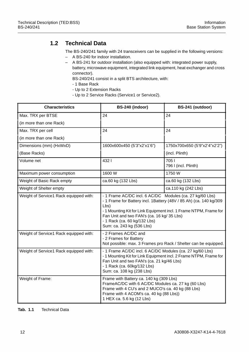
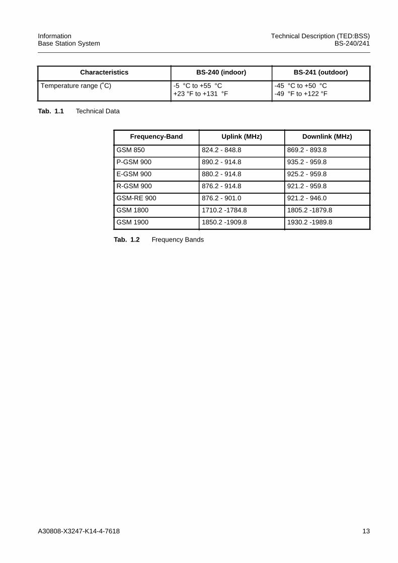
1.2 Technical DataThe BS-240/241 family with 24 transceivers can be supplied in the following versions:– A BS-240 for indoor installation.– A BS-241 for outdoor installation (also equipped with: integrated power supply,
battery, microwave equipment, integrated link equipment, heat exchanger and crossconnector).BS-240/241 consist in a split BTS architecture, with:- 1 Base Rack- Up to 2 Extension Racks- Up to 2 Service Racks (Service1 or Service2).
Characteristics BS-240 (indoor) BS-241 (outdoor)
Max. TRX per BTSE 24 24
(in more than one Rack)
Max. TRX per cell 24 24
(in more than one Rack)
Dimensions (mm) (HxWxD) 1600x600x450 (5’3”x2’x1’6”) 1750x700x650 (5’9”x2’4”x2’2”)
(Base Racks) (incl. Plinth)
Volume net 432 l 705 l796 l (incl. Plinth)
Maximum power consumption 1600 W 1750 W
Weight of Basic Rack empty ca.60 kg (132 Lbs) ca.60 kg (132 Lbs)
Weight of Shelter empty ca.110 kg (242 Lbs)
Weight of Service1 Rack equipped with: - 1 Frame AC/DC incl. 6 AC/DC Modules (ca. 27 kg/60 Lbs)- 1 Frame for Battery incl. 1Battery (48V / 85 Ah) (ca. 140 kg/309Lbs)- 1 Mounting Kit for Link Equipment incl. 1 Frame NTPM, Frame forFan Unit and two FAN's (ca. 16 kg/ 35 Lbs)- 1 Rack (ca. 60 kg/132 Lbs)Sum: ca. 243 kg (536 Lbs)
Weight of Service1 Rack equipped with: - 2 Frames AC/DC and- 2 Frames for BatteryNot possible: max. 3 Frames pro Rack / Shelter can be equipped.
Weight of Service1 Rack equipped with: - 1 Frame AC/DC incl. 6 AC/DC Modules (ca. 27 kg/60 Lbs)- 1 Mounting Kit for Link Equipment incl. 2 Frame NTPM, Frame forFan Unit and two FAN's (ca. 21 kg/46 Lbs)- 1 Rack (ca. 60kg/132 Lbs)Sum: ca. 108 kg (238 Lbs)
Weight of Frame: Frame with Battery ca. 140 kg (309 Lbs)FrameAC/DC with 6 AC/DC Modules ca. 27 kg (60 Lbs)Frame with 4 CU's and 2 MUCO's ca. 40 kg (88 Lbs)Frame with 4 ACOM's ca. 40 kg (88 Lbs))1 HEX ca. 5.6 kg (12 Lbs)
Tab. 1.1 Technical Data
A30808-X3247-K14-4-7618 13
InformationBase Station System
Technical Description (TED:BSS)BS-240/241
Temperature range (˚C) -5 °C to +55 °C+23 °F to +131 °F
-45 °C to +50 °C-49 °F to +122 °F
Characteristics BS-240 (indoor) BS-241 (outdoor)
Tab. 1.1 Technical Data
Frequency-Band Uplink (MHz) Downlink (MHz)
GSM 850 824.2 - 848.8 869.2 - 893.8
P-GSM 900 890.2 - 914.8 935.2 - 959.8
E-GSM 900 880.2 - 914.8 925.2 - 959.8
R-GSM 900 876.2 - 914.8 921.2 - 959.8
GSM-RE 900 876.2 - 901.0 921.2 - 946.0
GSM 1800 1710.2 -1784.8 1805.2 -1879.8
GSM 1900 1850.2 -1909.8 1930.2 -1989.8
Tab. 1.2 Frequency Bands
14 A30808-X3247-K14-4-7618
Technical Description (TED:BSS)BS-240/241
InformationBase Station System
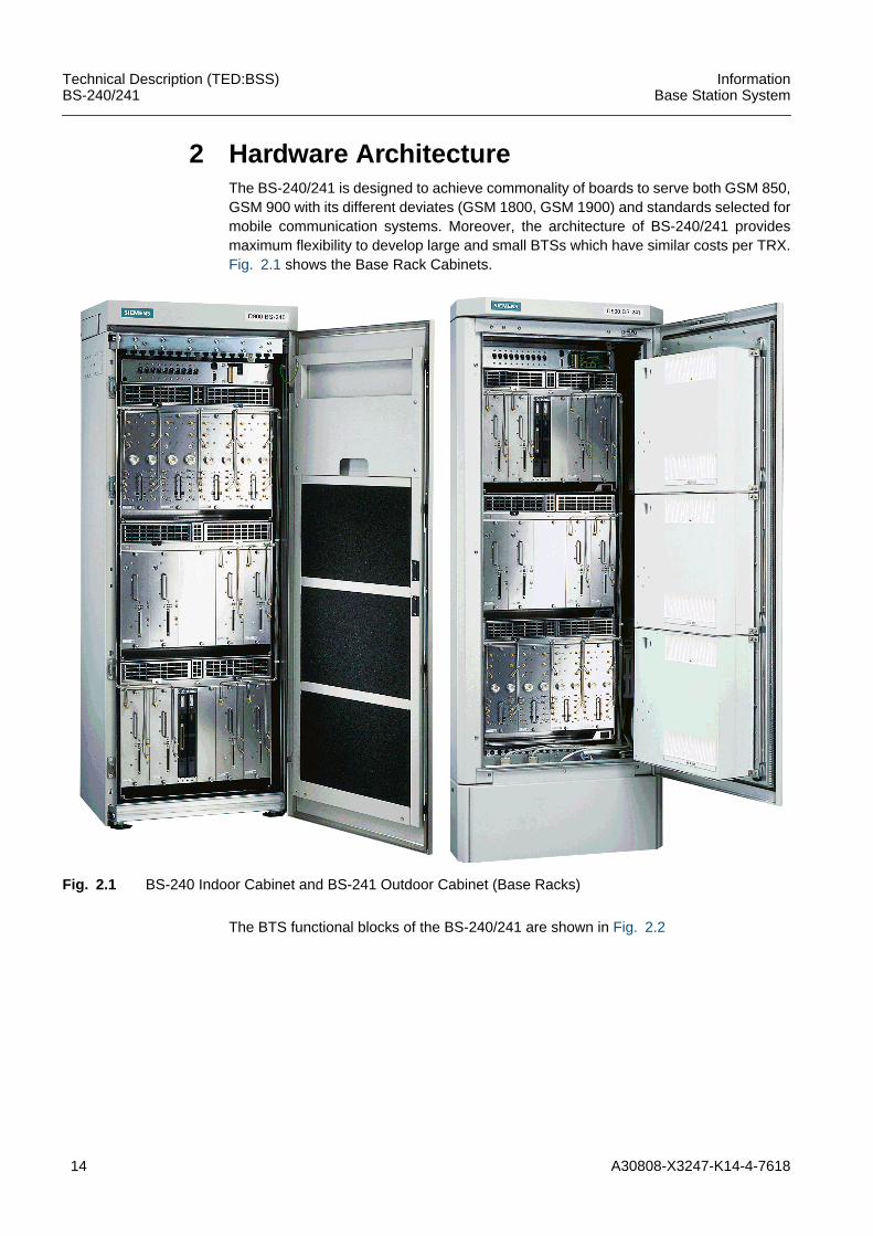
2 Hardware ArchitectureThe BS-240/241 is designed to achieve commonality of boards to serve both GSM 850,GSM 900 with its different deviates (GSM 1800, GSM 1900) and standards selected formobile communication systems. Moreover, the architecture of BS-240/241 providesmaximum flexibility to develop large and small BTSs which have similar costs per TRX.Fig. 2.1 shows the Base Rack Cabinets.
Fig. 2.1 BS-240 Indoor Cabinet and BS-241 Outdoor Cabinet (Base Racks)
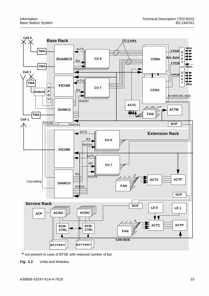
The BTS functional blocks of the BS-240/241 are shown in Fig. 2.2
A30808-X3247-K14-4-7618 15
InformationBase Station System
Technical Description (TED:BSS)BS-240/241
Fig. 2.2 Units and Modules
CU 7
CU 0
CU 7
Base Rack
Service Rack
DUAMCO CU 0
COSA
ACTM
CAN BUS
CC-Links
FICOM
DIAMCO
HPDU
4xTX
RX
RXDIV
4xTX
RX
RXDIV
ACTC ACTP
LE 0 LE 1
BATTERY
TMA
DCB-
ACP
CTRL
ACTC
FAN
Cell 0
Cell 1
FICOM
DIAMCO
4xTX
4xTX
RX
RXDIV
Cell 1
RX
RXDIV
RX
RXDIV
ACTC ACTP
FAN
to next ext. rack
RXCA1RXCA0
BATTERY
DCB-CTRL
AC/DCAC/DC
DCP
DCP
DCP
Extension Rack
Cascading
DUBIAS
COBA
2 PCM
Ext. Sync.
2 PCM
4 PCM
Abis
Sync.
Abis
TMA
FAN
TMA
TMA
OVPT
OVPT
* not present in case of BTSE with reduced number of fan
*
*
*
16 A30808-X3247-K14-4-7618
Technical Description (TED:BSS)BS-240/241
InformationBase Station System
The architecture of BS-240/241 provides maximum flexibility to develop large and smallBTSs.
The BS-240/241 mainly consists of:– carrier oriented boards called carrier unit (CU),– core boards (COSA, COBA) and– combining equipment
Up to 8 PCM lines can be connected to the core boards. In order to provide cost effectivesolutions for small and for large BTSs, the core boards are scalable (COBA, COSA). Inaddition, also the BTS itself is scalable. It is possible to connect up to 2 Extension Racksto a Base Rack.
The main communication between the modules is provided by means of bi-directionalserial link communications between the carrier units (CU) and the core boards. Theserial link also provides an effective means to realize baseband frequency hopping.Despite the fact that synchronization information is also transported via the serial links,no differential length constraints apply for the lines of the serial link.
All alarms, beside the alarms that are generated in the core and in the CU boards, aretransported via the CAN bus. Alarms of the CU boards are transmitted via CC-Link. Coreboards use their interface bus.
The carrier unit(s) provide all analog and digital signal processing including a RF powerstage necessary to process a single carrier (e.g., GSM 8 TCHs). The carrier unit(s) inter-face with the combining equipment on the one side and with the core modules on theother. The core boards provide functions common to all carriers within the BS-240/241(e.g., clock generation, O&M processing,...) as well as LAPD processing for the differentcarriers.
AC/DC AC/DC converter DCBCTRL DC and Battery ControllerACP AC Panel DCP DC PanelACTC Alarm Collection Terminal Connection module DIAMCO DI(2) Amplifier Multi CouplerACTM Optional Alarm Collection Terminal for Master Rack DUAMCO Duplex Amplifier MulticouplerACTP Alarm Collection Terminal for Slave Rack FICOM Filter CombinerCAN Controller Area Network HPDU High Power DuplexerCOBA Core Basis (COBA2P8) LE Link EquipmentCOSA Core Satellite (COSA6P16) TMA Tower Mounted AmplifierCU Carrier Unit
A30808-X3247-K14-4-7618 17
InformationBase Station System
Technical Description (TED:BSS)BS-240/241
2.1 Board RedundancyRedundancy in the SBS ensures survival of the system even in the event of multiple fail-ures. Modular architecture, in conjunction with the concept of split functions, guaranteesmaximum survivability with a minimum of additional hardware.
2.1.1 AC/DCUp to 6 AC/DC converters can be equipped in the service1 Rack which provide N+1redundancy. AC/DC converters work in load sharing, but n AC/DC are able to supply thewhole BS-240/241.
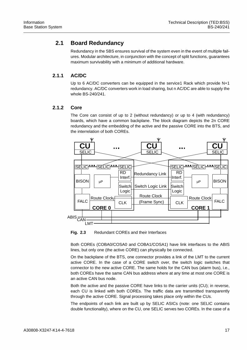
2.1.2 CoreThe Core can consist of up to 2 (without redundancy) or up to 4 (with redundancy)boards, which have a common backplane. The block diagram depicts the 2n COREredundancy and the embedding of the active and the passive CORE into the BTS, andthe interrelation of both COREs.
Fig. 2.3 Redundant COREs and their Interfaces
Both COREs (COBA0/COSA0 and COBA1/COSA1) have link interfaces to the ABISlines, but only one (the active CORE) can physically be connected.
On the backplane of the BTS, one connector provides a link of the LMT to the currentactive CORE. In the case of a CORE switch over, the switch logic switches thatconnector to the new active CORE. The same holds for the CAN bus (alarm bus), i.e.,both COREs have the same CAN bus address where at any time at most one CORE isan active CAN bus node.
Both the active and the passive CORE have links to the carrier units (CU); in reverse,each CU is linked with both COREs. The traffic data are transmitted transparentlythrough the active CORE. Signal processing takes place only within the CUs.
The endpoints of each link are built up by SELIC ASICs (note: one SELIC containsdouble functionality), where on the CU, one SELIC serves two COREs. In the case of a
CUSELIC
SELIC
BISON
RDInterf.
SwitchLogic
FALC
CORE 0CLK
Route Clock
Redundancy Link
Switch Logic Link
Route Clock(Frame Sync)
ABISCAN
LMT
µP
CUSELIC
CUSELIC
SELIC SELIC SELIC
BISON
RDInterf.
SwitchLogic
FALC
CORE 1CLK
Route Clock
µP
SELICSELIC
18 A30808-X3247-K14-4-7618
Technical Description (TED:BSS)BS-240/241
InformationBase Station System
switch over, the SELICs on the active CORE are disabled by the switch logic and theSELICs on the passive one are enabled. The SELICs on the CORE have to knowwhether they are on the active or on the passive CORE. For this reason the SELICsneed a active/passive pin, which is served by the redundancy switch logic. When aswitch over occurs, the switch logic sets the active/passive pin of the former activeSELICs to "passive" and that of the former passive SELICs to "active".
The SELICs on the CUs have to recognize automatically which link comes from theactive CORE and which link from the passive one, i.e. it has to recognise a CORE switchover by itself.
The RD interface (redundancy interface) is realized as a 2 Mbit/s HDLC link whichprovides a communication interface between the two main processors (mP).
The switch logic is a flip-flop distributed over the two COREs. It manages the HW partof a switch over and enables the COREs to know about their states as active/passive.
The ACLK of the active CORE is connected with the one on the passive CORE. It allowsthe passive ACLK to be synchronized to the active one.
NOTE: the redundancy is implemented in a cold-standby mode, i.e., all calls will get lostif a CORE switch over occurs.
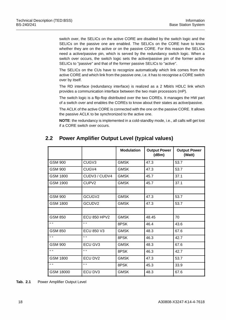
2.2 Power Amplifier Output Level (typical values)
Modulation Output Power(dBm)
Output Power(Watt)
GSM 900 CUGV3 GMSK 47.3 53.7
GSM 900 CUGV4 GMSK 47.3 53.7
GSM 1800 CUDV3 / CUDV4 GMSK 45.7 37.1
GSM 1900 CUPV2 GMSK 45.7 37.1
GSM 900 GCUGV2 GMSK 47.3 53.7
GSM 1800 GCUDV2 GMSK 47.3 53.7
GSM 850 ECU 850 HPV2 GMSK 48.45 70
“ “ “ “ 8PSK 46.4 43.6
GSM 850 ECU 850 V3 GMSK 48.3 67.6
“ “ “ “ 8PSK 46.3 42.7
GSM 900 ECU GV3 GMSK 48.3 67.6
“ “ “ “ 8PSK 46.3 42.7
GSM 1800 ECU DV2 GMSK 47.3 53.7
“ “ “ “ 8PSK 45.3 33.9
GSM 18000 ECU DV3 GMSK 48.3 67.6
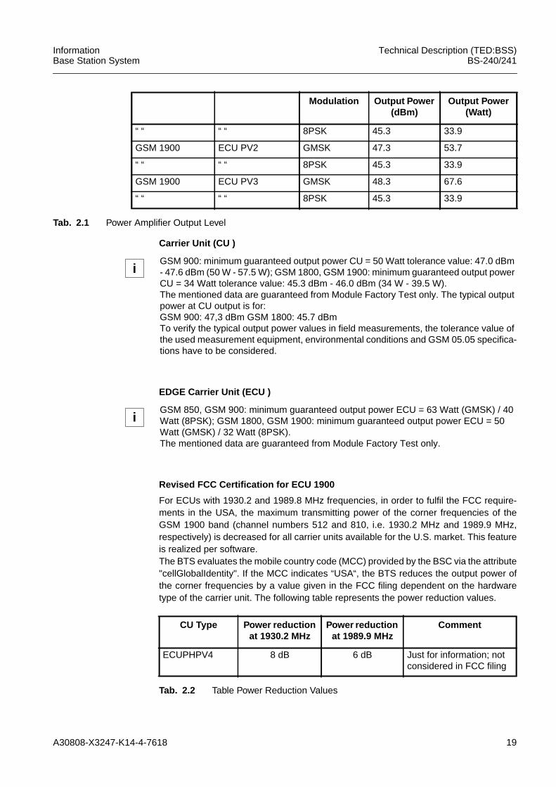
Tab. 2.1 Power Amplifier Output Level
A30808-X3247-K14-4-7618 19
InformationBase Station System
Technical Description (TED:BSS)BS-240/241
Carrier Unit (CU )
EDGE Carrier Unit (ECU )
Revised FCC Certification for ECU 1900
For ECUs with 1930.2 and 1989.8 MHz frequencies, in order to fulfil the FCC require-ments in the USA, the maximum transmitting power of the corner frequencies of theGSM 1900 band (channel numbers 512 and 810, i.e. 1930.2 MHz and 1989.9 MHz,respectively) is decreased for all carrier units available for the U.S. market. This featureis realized per software.The BTS evaluates the mobile country code (MCC) provided by the BSC via the attribute"cellGlobalIdentity". If the MCC indicates “USA“, the BTS reduces the output power ofthe corner frequencies by a value given in the FCC filing dependent on the hardwaretype of the carrier unit. The following table represents the power reduction values.
“ “ “ “ 8PSK 45.3 33.9
GSM 1900 ECU PV2 GMSK 47.3 53.7
“ “ “ “ 8PSK 45.3 33.9
GSM 1900 ECU PV3 GMSK 48.3 67.6
“ “ “ “ 8PSK 45.3 33.9
iGSM 900: minimum guaranteed output power CU = 50 Watt tolerance value: 47.0 dBm- 47.6 dBm (50 W - 57.5 W); GSM 1800, GSM 1900: minimum guaranteed output powerCU = 34 Watt tolerance value: 45.3 dBm - 46.0 dBm (34 W - 39.5 W).The mentioned data are guaranteed from Module Factory Test only. The typical outputpower at CU output is for:GSM 900: 47,3 dBm GSM 1800: 45.7 dBmTo verify the typical output power values in field measurements, the tolerance value ofthe used measurement equipment, environmental conditions and GSM 05.05 specifica-tions have to be considered.
Modulation Output Power(dBm)
Output Power(Watt)
Tab. 2.1 Power Amplifier Output Level
iGSM 850, GSM 900: minimum guaranteed output power ECU = 63 Watt (GMSK) / 40Watt (8PSK); GSM 1800, GSM 1900: minimum guaranteed output power ECU = 50Watt (GMSK) / 32 Watt (8PSK).The mentioned data are guaranteed from Module Factory Test only.
CU Type Power reductionat 1930.2 MHz
Power reductionat 1989.9 MHz
Comment
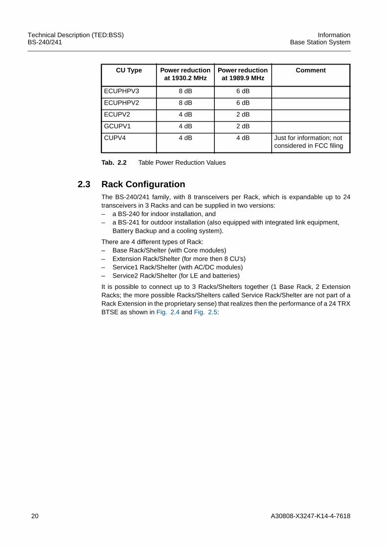
ECUPHPV4 8 dB 6 dB Just for information; notconsidered in FCC filing
Tab. 2.2 Table Power Reduction Values
20 A30808-X3247-K14-4-7618
Technical Description (TED:BSS)BS-240/241
InformationBase Station System
2.3 Rack ConfigurationThe BS-240/241 family, with 8 transceivers per Rack, which is expandable up to 24transceivers in 3 Racks and can be supplied in two versions:– a BS-240 for indoor installation, and– a BS-241 for outdoor installation (also equipped with integrated link equipment,
Battery Backup and a cooling system).
There are 4 different types of Rack:– Base Rack/Shelter (with Core modules)– Extension Rack/Shelter (for more then 8 CU’s)– Service1 Rack/Shelter (with AC/DC modules)– Service2 Rack/Shelter (for LE and batteries)
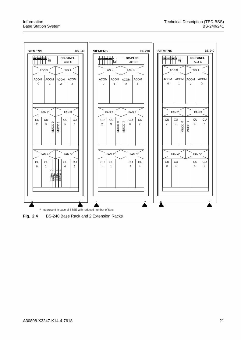
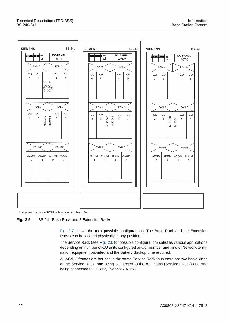
It is possible to connect up to 3 Racks/Shelters together (1 Base Rack, 2 ExtensionRacks; the more possible Racks/Shelters called Service Rack/Shelter are not part of aRack Extension in the proprietary sense) that realizes then the performance of a 24 TRXBTSE as shown in Fig. 2.4 and Fig. 2.5:
ECUPHPV3 8 dB 6 dB
ECUPHPV2 8 dB 6 dB
ECUPV2 4 dB 2 dB
GCUPV1 4 dB 2 dB
CUPV4 4 dB 4 dB Just for information; notconsidered in FCC filing
CU Type Power reductionat 1930.2 MHz
Power reductionat 1989.9 MHz
Comment
Tab. 2.2 Table Power Reduction Values
A30808-X3247-K14-4-7618 21
InformationBase Station System
Technical Description (TED:BSS)BS-240/241
Fig. 2.4 BS-240 Base Rack and 2 Extension Racks
ACOM
0
ACOM
1
ACOM
2
ACOM
3
DC-PANELACT-C
CU
2
CU
3
CU
6
CU
7
MU
CO
0
MU
CO
1
CU 0
CU 1
CU 4
CU 5
BS-240SIEMENS
ACOM
0
ACOM
1
ACOM
2
ACOM
3
CU
2
CU
3
CU
6
CU
7
MU
CO
0
MU
CO
1
CU
0
CU
1
CU
4
CU
5
BS-240SIEMENSC
OB
A 0
CO
SA
0C
OB
A 1
CO
SA
1
FAN 0 FAN 1
ACOM
0
ACOM
1
ACOM
2
ACOM
3
DC-PANELACT-C
CU
2
CU
3
CU
6
CU
7
MU
CO
0
MU
CO
1
CU 0
CU
1
CU 4
CU 5
BS-240SIEMENS
FAN 0 FAN 1
DC-PANELACT-C
FAN 0 FAN 1
FAN 2 FAN 3
FAN 4 * FAN 5*
FAN 2 FAN 3
FAN 4* FAN 5*
FAN 2 FAN 3
FAN 4* FAN 5*
* not present in case of BTSE with reduced number of fans
22 A30808-X3247-K14-4-7618
Technical Description (TED:BSS)BS-240/241
InformationBase Station System
Fig. 2.5 BS-241 Base Rack and 2 Extension Racks
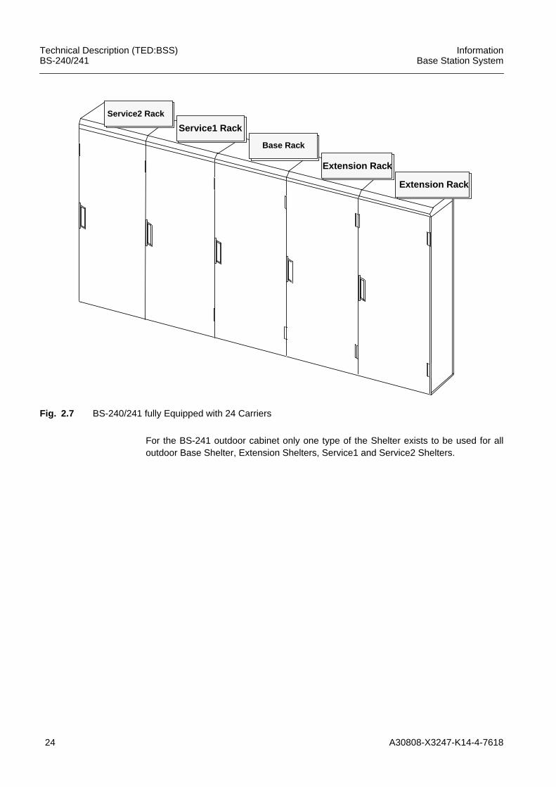
Fig. 2.7 shows the max possible configurations. The Base Rack and the ExtensionRacks can be located physically in any position.
The Service Rack (see Fig. 2.6 for possible configuration) satisfies various applicationsdepending on number of CU units configured and/or number and kind of Network termi-nation equipment provided and the Battery Backup time required.
All AC/DC frames are housed in the same Service Rack thus there are two basic kindsof the Service Rack, one being connected to the AC mains (Service1 Rack) and onebeing connected to DC only (Service2 Rack).
CU
2
CU
3
CU
6
CU
7
MU
CO
0
MU
CO
1
CU
0
CU
1
CU
4
CU
5
BS-241SIEMENS
CO
BA
0C
OS
A 0
CO
BA
1C
OS
A1
DC-PANELACT-C
FAN 0 FAN 1
FAN 2 FAN 3
FAN 4* FAN 5*
ACOM
0
ACOM
1
ACOM
2
ACOM
3
CU
2
CU
3
CU
6
CU
7
MU
CO
0
MU
CO
1
CU
0
CU
1
CU
4
CU
5
BS-241SIEMENS
DC-PANELACT-C
FAN 0 FAN 1
FAN 2 FAN 3
FAN 4* FAN 5*
ACOM
0
ACOM
1
ACOM
2
ACOM
3
CU
2
CU
3
CU
6
CU
7
MU
CO
0
MU
CO
1
CU
0
CU
1
CU
4
CU
5
BS-241SIEMENS
DC-PANELACT-C
FAN 0 FAN 1
FAN 2 FAN 3
FAN 4* FAN 5*
ACOM
0
ACOM
1
ACOM
2
ACOM
3
* not present in case of BTSE with reduced number of fans
A30808-X3247-K14-4-7618 23
InformationBase Station System
Technical Description (TED:BSS)BS-240/241
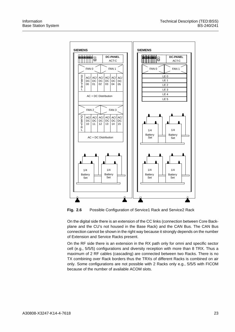
Fig. 2.6 Possible Configuration of Service1 Rack and Service2 Rack
On the digital side there is an extension of the CC links (connection between Core Back-plane and the CU’s not housed in the Base Rack) and the CAN Bus. The CAN Busconnection cannot be shown in the right way because it strongly depends on the numberof Extension and Service Racks present.
On the RF side there is an extension in the RX path only for omni and specific sectorcell (e.g., 5/5/5) configurations and diversity reception with more than 8 TRX. Thus amaximum of 2 RF cables (cascading) are connected between two Racks. There is noTX combining over Rack borders thus the TRXs of different Racks is combined on aironly. Some configurations are not possible with 2 Racks only e.g., 5/5/5 with FICOMbecause of the number of available ACOM slots.
AC/
SIEMENS
DC-PANELACT-C
SIEMENS
FAN 0 FAN 1
DC-PANELACT-C
FAN 0 FAN 1
FAN 2 FAN 3
DC05
AC/DC00
AC/DC01
AC/DC02
AC/DC03
AC/DC04
AC + DC Distribution
AC/DC15
AC/DC10
AC/DC11
AC/DC12
AC/DC13
AC/DC14
AC + DC Distribution
1/4
Battery
1/4
Battery
LE 0
LE 1
LE 2
LE 3
LE 4
LE 5
1/4
Battery
1/4
Battery
1/4
Battery
1/4
Battery
D
CTRL
CB
D
CTRL
CB
Set Set
Set Set Set Set
24 A30808-X3247-K14-4-7618
Technical Description (TED:BSS)BS-240/241
InformationBase Station System
Fig. 2.7 BS-240/241 fully Equipped with 24 Carriers
For the BS-241 outdoor cabinet only one type of the Shelter exists to be used for alloutdoor Base Shelter, Extension Shelters, Service1 and Service2 Shelters.
Extension Rack
Base Rack
Service1 Rack
Service2 Rack
Extension Rack
A30808-X3247-K14-4-7618 25
InformationBase Station System
Technical Description (TED:BSS)BS-240/241
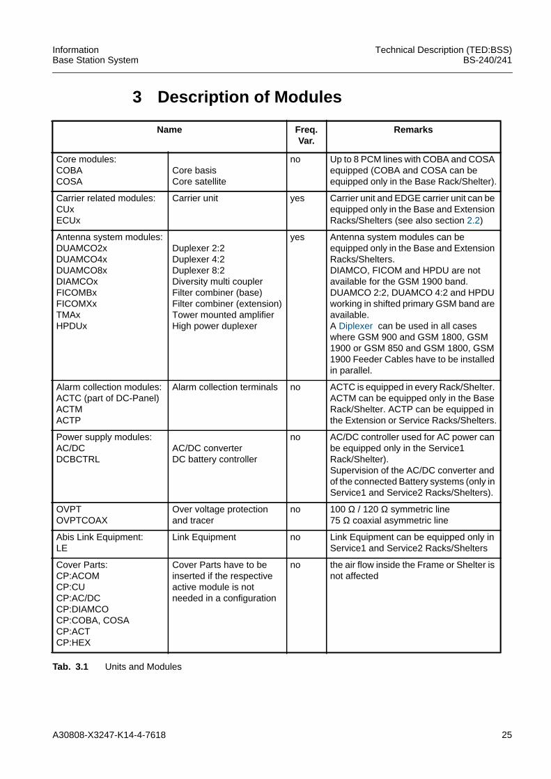
3 Description of Modules
Name Freq.Var.
Remarks
Core modules:COBACOSA
Core basisCore satellite
no Up to 8 PCM lines with COBA and COSAequipped (COBA and COSA can beequipped only in the Base Rack/Shelter).
Carrier related modules:CUxECUx
Carrier unit yes Carrier unit and EDGE carrier unit can beequipped only in the Base and ExtensionRacks/Shelters (see also section 2.2)
Antenna system modules:DUAMCO2xDUAMCO4xDUAMCO8xDIAMCOxFICOMBxFICOMXxTMAxHPDUx
Duplexer 2:2Duplexer 4:2Duplexer 8:2Diversity multi couplerFilter combiner (base)Filter combiner (extension)Tower mounted amplifierHigh power duplexer
yes Antenna system modules can beequipped only in the Base and ExtensionRacks/Shelters.DIAMCO, FICOM and HPDU are notavailable for the GSM 1900 band.DUAMCO 2:2, DUAMCO 4:2 and HPDUworking in shifted primary GSM band areavailable.A Diplexer can be used in all caseswhere GSM 900 and GSM 1800, GSM1900 or GSM 850 and GSM 1800, GSM1900 Feeder Cables have to be installedin parallel.
Alarm collection modules:ACTC (part of DC-Panel)ACTMACTP
Alarm collection terminals no ACTC is equipped in every Rack/Shelter.ACTM can be equipped only in the BaseRack/Shelter. ACTP can be equipped inthe Extension or Service Racks/Shelters.
Power supply modules:AC/DCDCBCTRL
AC/DC converterDC battery controller
no AC/DC controller used for AC power canbe equipped only in the Service1Rack/Shelter).Supervision of the AC/DC converter andof the connected Battery systems (only inService1 and Service2 Racks/Shelters).
OVPTOVPTCOAX
Over voltage protectionand tracer
no 100 Ω / 120 Ω symmetric line75 Ω coaxial asymmetric line
Abis Link Equipment:LE
Link Equipment no Link Equipment can be equipped only inService1 and Service2 Racks/Shelters
Cover Parts:CP:ACOMCP:CUCP:AC/DCCP:DIAMCOCP:COBA, COSACP:ACTCP:HEX
Cover Parts have to beinserted if the respectiveactive module is notneeded in a configuration
no the air flow inside the Frame or Shelter isnot affected
Tab. 3.1 Units and Modules
26 A30808-X3247-K14-4-7618
Technical Description (TED:BSS)BS-240/241
InformationBase Station System
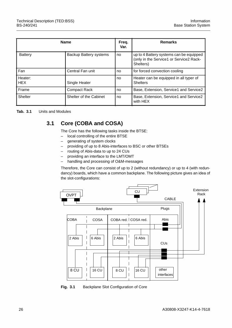
3.1 Core (COBA and COSA)The Core has the following tasks inside the BTSE:– local controlling of the entire BTSE– generating of system clocks– providing of up to 8 Abis-interfaces to BSC or other BTSEs– routing of Abis-data to up to 24 CUs– providing an interface to the LMT/OMT– handling and processing of O&M-messages
Therefore, the Core can consist of up to 2 (without redundancy) or up to 4 (with redun-dancy) boards, which have a common backplane. The following picture gives an idea ofthe slot-configurations:
Fig. 3.1 Backplane Slot Configuration of Core
Battery Backup Battery systems no up to 4 Battery systems can be equipped(only in the Service1 or Service2 Rack-Shelters)
Fan Central Fan unit no for forced convection cooling
Heater:HEX Single Heater
no Heater can be equipped in all typer ofShelters
Frame Compact Rack no Base, Extension, Service1 and Service2
Shelter Shelter of the Cabinet no Base, Extension, Service1 and Service2with HEX
Name Freq.Var.
Remarks
Tab. 3.1 Units and Modules
CABLE
2 Abis 6 Abis
COBA COSA COBA red. COSA red.
2 Abis 6 Abis
Abis
8 CU 16 CU 8 CU 16 CU other
interfaces
Backplane Plugs
Extension
CUs
CUOVPT Rack
A30808-X3247-K14-4-7618 27
InformationBase Station System
Technical Description (TED:BSS)BS-240/241
For a configuration with less or equal 2 PCM30/24-interfaces and no Extension Rackone COBA-board is required. The second slot can be used (by adding 1 COSA Board)for an expansion of the BTSE up to 8 Abis- and 24 CU-interfaces or it can be used forfuture expansions, e.g. a GPS-Receiver for synchronization, better frequency-standardsor other Abis-interfaces than PCM30/24 (e.g., SDH, ATM).
The connection of Abis- and CU-interfaces of the Core to the OVPT/Abis-interface andthe CUs is done via cables, which are plugged into the backplane.
The CU-interfaces of the Core and its redundancy are routed with separated wires viathe backplane and cables to the CUs (2 interfaces on one CU required).
The Abis-interface-ports of the Core and its redundancy-ports can only be switched tothe same wires. Only one transceiver at the same time is allowed to be switched to thesame wires (no simultaneous transmitting/receiving of Core and its redundancy on thesame Abis-port possible).
To find the physical place of a Abis-interface/CU out of the logical/memory-mapaddress, appropriate configuration-rules are created and considered.
Two Core-boards, COBA2P8 (see section 3.1.1) and COSA6P16 (see section 3.1.2),are developed. The first digit gives the number of Abis-Interfaces, the following letter thekind of Abis-interface (e.g. P for PCM30/24), and the following number the number ofCU-interfaces, e.g., COSA6P16 (6 PCM30/24 Abis-interfaces, 16 CU interfaces).
Hot Plug-in: A Hot Plug-in of the Core-boards (COBA and COSA) is possible. Thismeans, that these boards can be plugged in/out with voltage switched on and no otherHW inside the Rack is disturbed (no loss of data on other boards) or a board isdestroyed.
After plug-in of a Core-board, this board is in the reset-state and all bus-drivers ofexternal busses are in tristate. These drivers shall be enabled not before initialization ofthe devices, which serve the external busses.
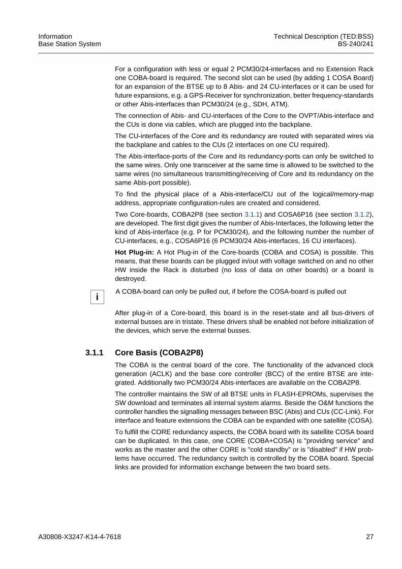
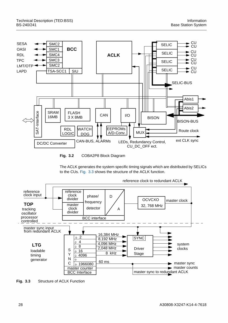
3.1.1 Core Basis (COBA2P8)The COBA is the central board of the core. The functionality of the advanced clockgeneration (ACLK) and the base core controller (BCC) of the entire BTSE are inte-grated. Additionally two PCM30/24 Abis-interfaces are available on the COBA2P8.
The controller maintains the SW of all BTSE units in FLASH-EPROMs, supervises theSW download and terminates all internal system alarms. Beside the O&M functions thecontroller handles the signalling messages between BSC (Abis) and CUs (CC-Link). Forinterface and feature extensions the COBA can be expanded with one satellite (COSA).
To fulfill the CORE redundancy aspects, the COBA board with its satellite COSA boardcan be duplicated. In this case, one CORE (COBA+COSA) is "providing service" andworks as the master and the other CORE is "cold standby" or is "disabled" if HW prob-lems have occurred. The redundancy switch is controlled by the COBA board. Speciallinks are provided for information exchange between the two board sets.
iA COBA-board can only be pulled out, if before the COSA-board is pulled out
28 A30808-X3247-K14-4-7618
Technical Description (TED:BSS)BS-240/241
InformationBase Station System
Fig. 3.2 COBA2P8 Block Diagram
The ACLK generates the system specific timing signals which are distributed by SELICsto the CUs. Fig. 3.3 shows the structure of the ACLK function.
Fig. 3.3 Structure of ACLK Function
SMC2SMC1SMC4SMC3SMC2
TSA-SCC1 SIU
BCCSESA
OASI
RDL
TPCLMT/OTPLAPD
ACLK
SELIC
SELIC
SELIC
SELIC
CUCUCUCUCUCUCUCU
SELIC-BUS
Abis1
Abis2
BISON-BUS
SA
T-I
nter
face
DC/DC Converter
SRAM16MB
FLASH3 X 8MB CAN I/O
BISON
RDLLOGIC
WATCHDOG
EEPROMsA/D-Conv. MUX
CAN-BUS, ALARMs LEDs, Redundancy Control,CU_DC_OFF ect.
Route clock
ext CLK sync
referenceclockdivider
masterclock
divider
phase/
frequency
detector
D
A
BCC interface
OCVCXO
32, 768 MHzmaster clock
referenceclock input
TOPtrackingoscillatorprocessorcontrolled
master sync inputfrom redundant ACLK
LTGloadabletiminggenerator
248164096
1966080master counterBCC Interface
SYNC
16,384 MHz 8,192 MHz 4,096 MHz 2,048 MHz
8 kHz
60 ms
SYNC
DriverStage
systemclocks
master syncmaster counts
master sync to redundant ACLK
reference clock to redundant ACLK
A30808-X3247-K14-4-7618 29
InformationBase Station System
Technical Description (TED:BSS)BS-240/241
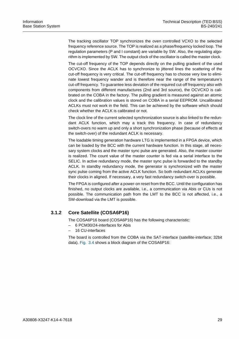
The tracking oscillator TOP synchronizes the oven controlled VCXO to the selectedfrequency reference source. The TOP is realized as a phase/frequency locked loop. Theregulation parameters (P and I constant) are variable by SW. Also, the regulating algo-rithm is implemented by SW. The output clock of the oscillator is called the master clock.
The cut-off frequency of the TOP depends directly on the pulling gradient of the usedOCVCXO. Since the ACLK has to synchronize to jittered lines the scattering of thecut-off frequency is very critical. The cut-off frequency has to choose very low to elimi-nate lowest frequency wander and is therefore near the range of the temperature’scut-off frequency. To guarantee less deviation of the required cut-off frequency also withcomponents from different manufactures (2nd and 3rd source), the OCVCXO is cali-brated on the COBA in the factory. The pulling gradient is measured against an atomicclock and the calibration values is stored on COBA in a serial EEPROM. UncalibratedACLKs must not work in the field. This can be achieved by the software which shouldcheck whether the ACLK is calibrated or not.
The clock line of the current selected synchronization source is also linked to the redun-dant ACLK function, which may a track this frequency. In case of redundancyswitch-overs no warm up and only a short synchronization phase (because of effects atthe switch-over) of the redundant ACLK is necessary.
The loadable timing generation hardware LTG is implemented in a FPGA device, whichcan be loaded by the BCC with the current hardware function. In this stage, all neces-sary system clocks and the master sync pulse are generated. Also, the master counteris realized. The count value of the master counter is fed via a serial interface to theSELIC. In active redundancy mode, the master sync pulse is forwarded to the standbyACLK. In standby redundancy mode, the generator is synchronized with the mastersync pulse coming from the active ACLK function. So both redundant ACLKs generatetheir clocks in aligned. If necessary, a very fast redundancy switch-over is possible.
The FPGA is configured after a power-on reset from the BCC. Until the configuration hasfinished, no output clocks are available, i.e., a communication via Abis or CUs is notpossible. The communication path from the LMT to the BCC is not affected, i.e., aSW-download via the LMT is possible.
3.1.2 Core Satellite (COSA6P16)The COSA6P16 board (COSA6P16) has the following characteristic:– 6 PCM30/24-interfaces for Abis– 16 CU-interfaces
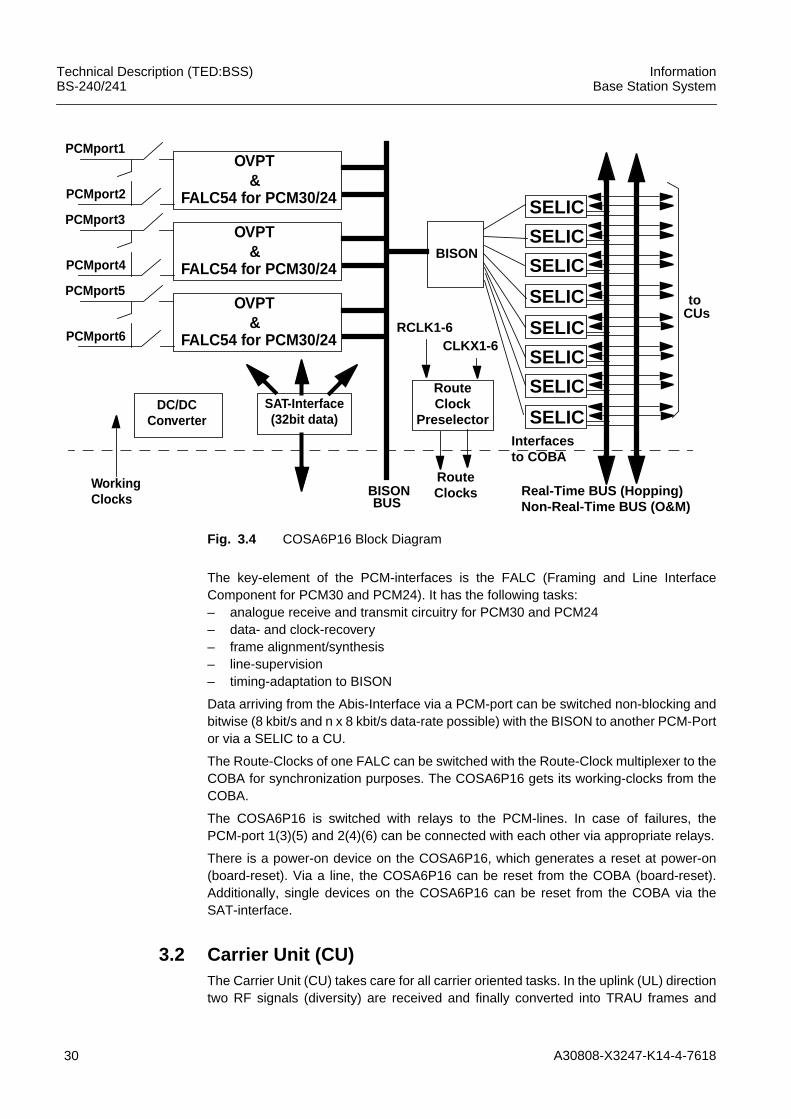
The board is controlled from the COBA via the SAT-interface (satellite-interface; 32bitdata). Fig. 3.4 shows a block diagram of the COSA6P16:
30 A30808-X3247-K14-4-7618
Technical Description (TED:BSS)BS-240/241
InformationBase Station System
Fig. 3.4 COSA6P16 Block Diagram
The key-element of the PCM-interfaces is the FALC (Framing and Line InterfaceComponent for PCM30 and PCM24). It has the following tasks:– analogue receive and transmit circuitry for PCM30 and PCM24– data- and clock-recovery– frame alignment/synthesis– line-supervision– timing-adaptation to BISON
Data arriving from the Abis-Interface via a PCM-port can be switched non-blocking andbitwise (8 kbit/s and n x 8 kbit/s data-rate possible) with the BISON to another PCM-Portor via a SELIC to a CU.
The Route-Clocks of one FALC can be switched with the Route-Clock multiplexer to theCOBA for synchronization purposes. The COSA6P16 gets its working-clocks from theCOBA.
The COSA6P16 is switched with relays to the PCM-lines. In case of failures, thePCM-port 1(3)(5) and 2(4)(6) can be connected with each other via appropriate relays.
There is a power-on device on the COSA6P16, which generates a reset at power-on(board-reset). Via a line, the COSA6P16 can be reset from the COBA (board-reset).Additionally, single devices on the COSA6P16 can be reset from the COBA via theSAT-interface.
3.2 Carrier Unit (CU)The Carrier Unit (CU) takes care for all carrier oriented tasks. In the uplink (UL) directiontwo RF signals (diversity) are received and finally converted into TRAU frames and
SELIC
BISON
OVPT
FALC54 for PCM30/24&
PCMport5
PCMport6
Interfacesto COBA
Real-Time BUS (Hopping)Non-Real-Time BUS (O&M)
toCUs
BISONBUS
RouteClocks
RouteClock
Preselector
RCLK1-6CLKX1-6
WorkingClocks
DC/DCConverter
SAT-Interface(32bit data)
SELIC
SELIC
SELIC
SELIC
SELIC
SELIC
SELIC
OVPT
FALC54 for PCM30/24&
PCMport1
PCMport2
OVPT
FALC54 for PCM30/24&
PCMport3
PCMport4
A30808-X3247-K14-4-7618 31
InformationBase Station System
Technical Description (TED:BSS)BS-240/241
signalling data. In the downlink (DL) direction, TRAU frames and signalling data arereceived and converted into a GMSK modulated RF signal, which is amplified to thedesired power level.
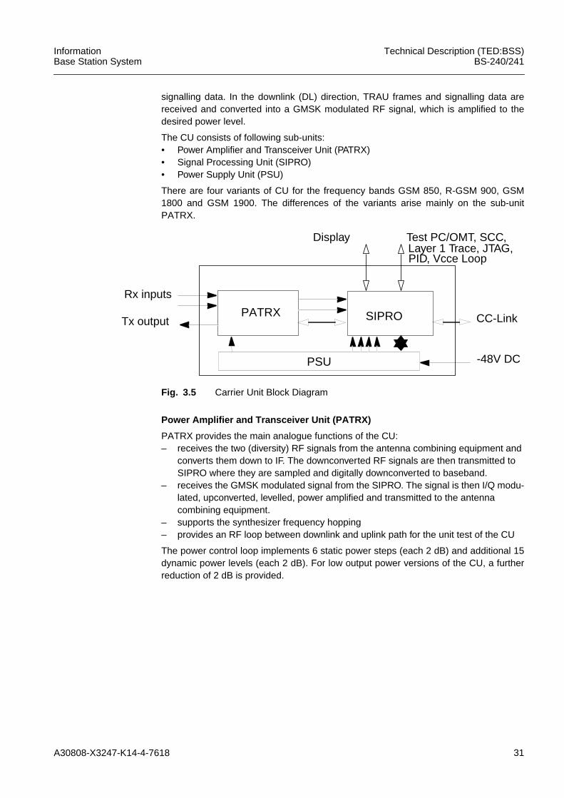
The CU consists of following sub-units:• Power Amplifier and Transceiver Unit (PATRX)• Signal Processing Unit (SIPRO)• Power Supply Unit (PSU)
There are four variants of CU for the frequency bands GSM 850, R-GSM 900, GSM1800 and GSM 1900. The differences of the variants arise mainly on the sub-unitPATRX.
Fig. 3.5 Carrier Unit Block Diagram
Power Amplifier and Transceiver Unit (PATRX)
PATRX provides the main analogue functions of the CU:– receives the two (diversity) RF signals from the antenna combining equipment and
converts them down to IF. The downconverted RF signals are then transmitted toSIPRO where they are sampled and digitally downconverted to baseband.
– receives the GMSK modulated signal from the SIPRO. The signal is then I/Q modu-lated, upconverted, levelled, power amplified and transmitted to the antennacombining equipment.
– supports the synthesizer frequency hopping– provides an RF loop between downlink and uplink path for the unit test of the CU
The power control loop implements 6 static power steps (each 2 dB) and additional 15dynamic power levels (each 2 dB). For low output power versions of the CU, a furtherreduction of 2 dB is provided.
SIPRO
PSU
PATRX CC-Link
-48V DC
Rx inputs
Tx output
Test PC/OMT, SCC,Layer 1 Trace, JTAG,PID, Vcce Loop
Display
32 A30808-X3247-K14-4-7618
Technical Description (TED:BSS)BS-240/241
InformationBase Station System
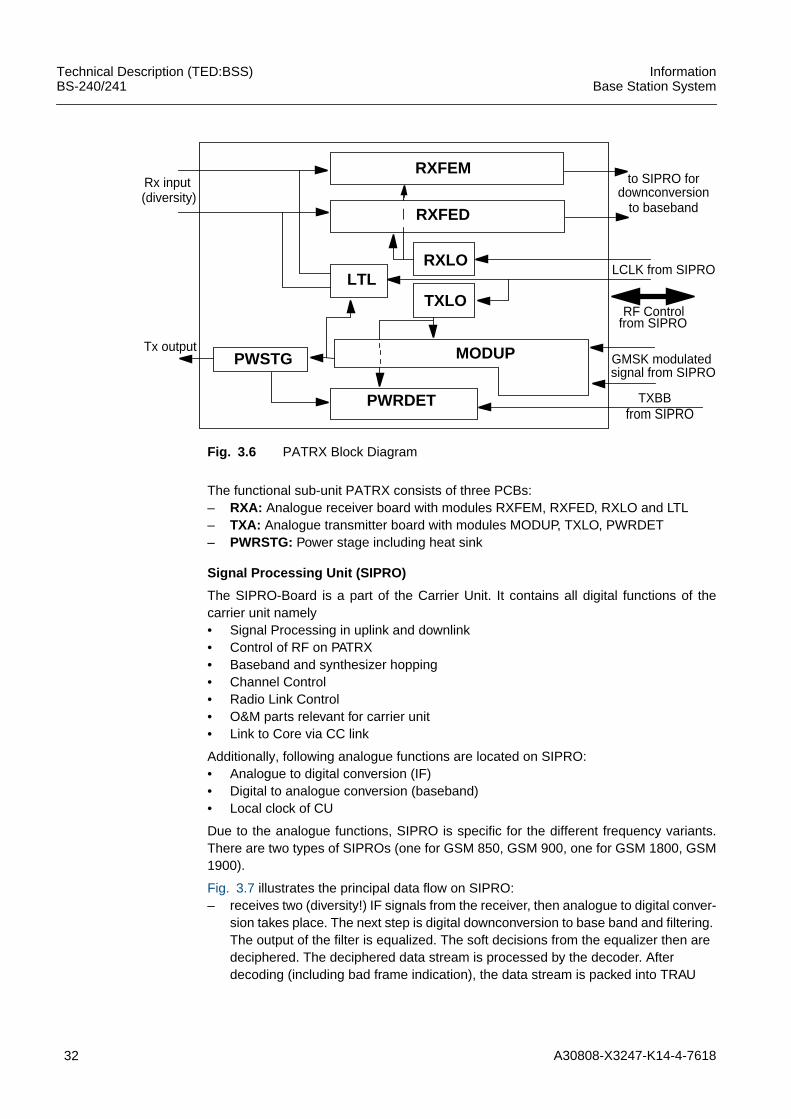
Fig. 3.6 PATRX Block Diagram
The functional sub-unit PATRX consists of three PCBs:– RXA: Analogue receiver board with modules RXFEM, RXFED, RXLO and LTL– TXA: Analogue transmitter board with modules MODUP, TXLO, PWRDET– PWRSTG: Power stage including heat sink
Signal Processing Unit (SIPRO)
The SIPRO-Board is a part of the Carrier Unit. It contains all digital functions of thecarrier unit namely• Signal Processing in uplink and downlink• Control of RF on PATRX• Baseband and synthesizer hopping• Channel Control• Radio Link Control• O&M parts relevant for carrier unit• Link to Core via CC link
Additionally, following analogue functions are located on SIPRO:• Analogue to digital conversion (IF)• Digital to analogue conversion (baseband)• Local clock of CU
Due to the analogue functions, SIPRO is specific for the different frequency variants.There are two types of SIPROs (one for GSM 850, GSM 900, one for GSM 1800, GSM1900).
Fig. 3.7 illustrates the principal data flow on SIPRO:– receives two (diversity!) IF signals from the receiver, then analogue to digital conver-
sion takes place. The next step is digital downconversion to base band and filtering.The output of the filter is equalized. The soft decisions from the equalizer then aredeciphered. The deciphered data stream is processed by the decoder. Afterdecoding (including bad frame indication), the data stream is packed into TRAU
to SIPRO for
LCLK from SIPRO
GMSK modulated
TXBB
Rx input
Tx output
RXFEM
RXFED
RXLO
TXLOLTL
PWSTG MODUP
PWRDET
(diversity) downconversionto baseband
signal from SIPRO
RF Controlfrom SIPRO
from SIPRO
A30808-X3247-K14-4-7618 33
InformationBase Station System
Technical Description (TED:BSS)BS-240/241
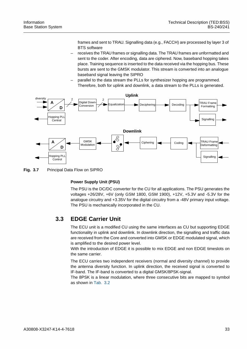
frames and sent to TRAU. Signalling data (e.g., FACCH) are processed by layer 3 ofBTS software
– receives the TRAU frames or signalling data. The TRAU frames are unformatted andsent to the coder. After encoding, data are ciphered. Now, baseband hopping takesplace. Training sequence is inserted to the data received via the hopping bus. Thesebursts are sent to the GMSK modulator. This stream is converted into an analoguebaseband signal leaving the SIPRO
– parallel to the data stream the PLLs for synthesizer hopping are programmed.Therefore, both for uplink and downlink, a data stream to the PLLs is generated.
Fig. 3.7 Principal Data Flow on SIPRO
Power Supply Unit (PSU)
The PSU is the DC/DC converter for the CU for all applications. The PSU generates thevoltages +26/28V, +6V (only GSM 1800, GSM 1900), +12V, +5.3V and -5.3V for theanalogue circuitry and +3.35V for the digital circuitry from a -48V primary input voltage.The PSU is mechanically incorporated in the CU.
3.3 EDGE Carrier UnitThe ECU unit is a modified CU using the same interfaces as CU but supporting EDGEfunctionality in uplink and downlink. In downlink direction, the signalling and traffic dataare received from the Core and converted into GMSK or EDGE modulated signal, whichis amplified to the desired power level.With the introduction of EDGE it is possible to mix EDGE and non EDGE timeslots onthe same carrier.
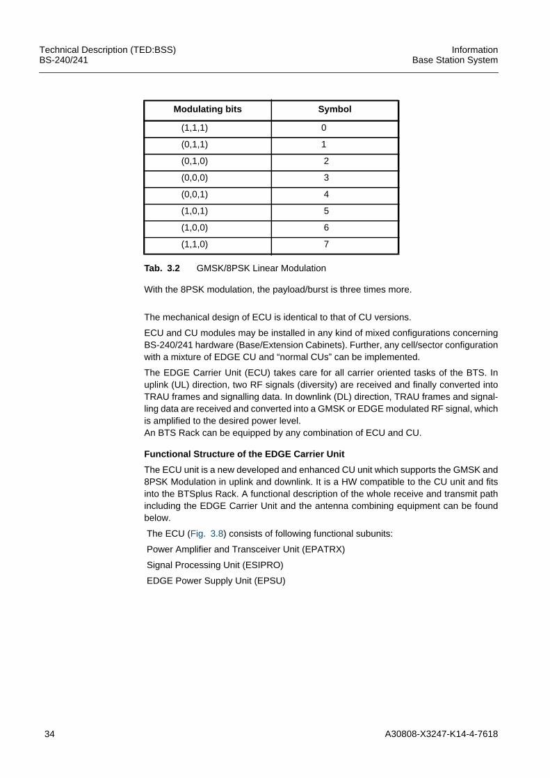
The ECU carries two independent receivers (normal and diversity channel) to providethe antenna diversity function. In uplink direction, the received signal is converted toIF-band. The IF-band is converted to a digital GMSK/8PSK-signal.The 8PSK is a linear modulation, where three consecutive bits are mapped to symbolas shown in Tab. 3.2
Uplink
Downlink
AD
AD
Hopping PLL
Hopping PLLControl
Central
diversity 2 2Digital Down-Conversion Equalization Deciphering Decoding
TRAU FrameFormatting
Signalling
TRAU FrameDeformatting
Signalling
CodingCipheringGMSKModulation
34 A30808-X3247-K14-4-7618
Technical Description (TED:BSS)BS-240/241
InformationBase Station System
With the 8PSK modulation, the payload/burst is three times more.
The mechanical design of ECU is identical to that of CU versions.
ECU and CU modules may be installed in any kind of mixed configurations concerningBS-240/241 hardware (Base/Extension Cabinets). Further, any cell/sector configurationwith a mixture of EDGE CU and “normal CUs” can be implemented.
The EDGE Carrier Unit (ECU) takes care for all carrier oriented tasks of the BTS. Inuplink (UL) direction, two RF signals (diversity) are received and finally converted intoTRAU frames and signalling data. In downlink (DL) direction, TRAU frames and signal-ling data are received and converted into a GMSK or EDGE modulated RF signal, whichis amplified to the desired power level.An BTS Rack can be equipped by any combination of ECU and CU.
Functional Structure of the EDGE Carrier Unit
The ECU unit is a new developed and enhanced CU unit which supports the GMSK and8PSK Modulation in uplink and downlink. It is a HW compatible to the CU unit and fitsinto the BTSplus Rack. A functional description of the whole receive and transmit pathincluding the EDGE Carrier Unit and the antenna combining equipment can be foundbelow.
The ECU (Fig. 3.8) consists of following functional subunits:
Power Amplifier and Transceiver Unit (EPATRX)
Signal Processing Unit (ESIPRO)
EDGE Power Supply Unit (EPSU)
Modulating bits Symbol
(1,1,1) 0
(0,1,1) 1
(0,1,0) 2
(0,0,0) 3
(0,0,1) 4
(1,0,1) 5
(1,0,0) 6
(1,1,0) 7
Tab. 3.2 GMSK/8PSK Linear Modulation
A30808-X3247-K14-4-7618 35
InformationBase Station System
Technical Description (TED:BSS)BS-240/241
Fig. 3.8 EPATRX and ESIPRO Function Block Diagram
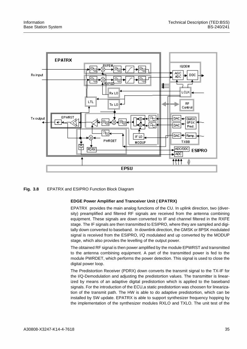
EDGE Power Amplifier and Tranceiver Unit ( EPATRX)
EPATRX provides the main analog functions of the CU. In uplink direction, two (diver-sity) preamplified and filtered RF signals are received from the antenna combiningequipment. These signals are down converted to IF and channel filtered in the RXFEstage. The IF signals are then transmitted to ESIPRO, where they are sampled and digi-tally down converted to baseband. In downlink direction, the GMSK or 8PSK modulatedsignal is received from the ESIPRO, I/Q modulated and up converted by the MODUPstage, which also provides the levelling of the output power.
The obtained RF signal is then power amplified by the module EPWRST and transmittedto the antenna combining equipment. A part of the transmitted power is fed to themodule PWRDET, which performs the power detection. This signal is used to close thedigital power loop.
The Predistortion Receiver (PDRX) down converts the transmit signal to the TX-IF forthe I/Q-Demodulation and adjusting the predistortion values. The transmitter is linear-ized by means of an adaptive digital predistortion which is applied to the basebandsignals. For the introduction of the ECU,a static predistortion was choosen for lineariza-tion of the transmit path. The HW is able to do adaptive predistortion, which can beinstalled by SW update. EPATRX is able to support synthesizer frequency hopping bythe implementation of the synthesizer modules RXLO and TXLO. The unit test of the
36 A30808-X3247-K14-4-7618
Technical Description (TED:BSS)BS-240/241
InformationBase Station System
ECU is supported by the module LTL, which provides an RF loop between downlink anduplink path.
Signal Processing Unit (ESIPRO)
The ESIPRO-Board of the BTSPLUS is a part of the Carrier Unit. It contains thefollowing functions of the Carrier Unit:– Signal Processing in uplink and downlink– Control of RF on EPATRX– Baseband and synthesizer frequency hopping– Channel Control– Radio Link Control– O&M parts relevant for carrier unit– Link to Core via ASIC SELIC– Digital Modulation– Predistortion signal processing– Digital part of Power control– Analog to digital conversion (RXIF)– Digital to analog conversion (TX-baseband, TX-ramping)– Analog to digital conversion (PDRX)– Analog to digital conversion of Diode voltage– Analog to digital conversion of temperature– Local clock of CU
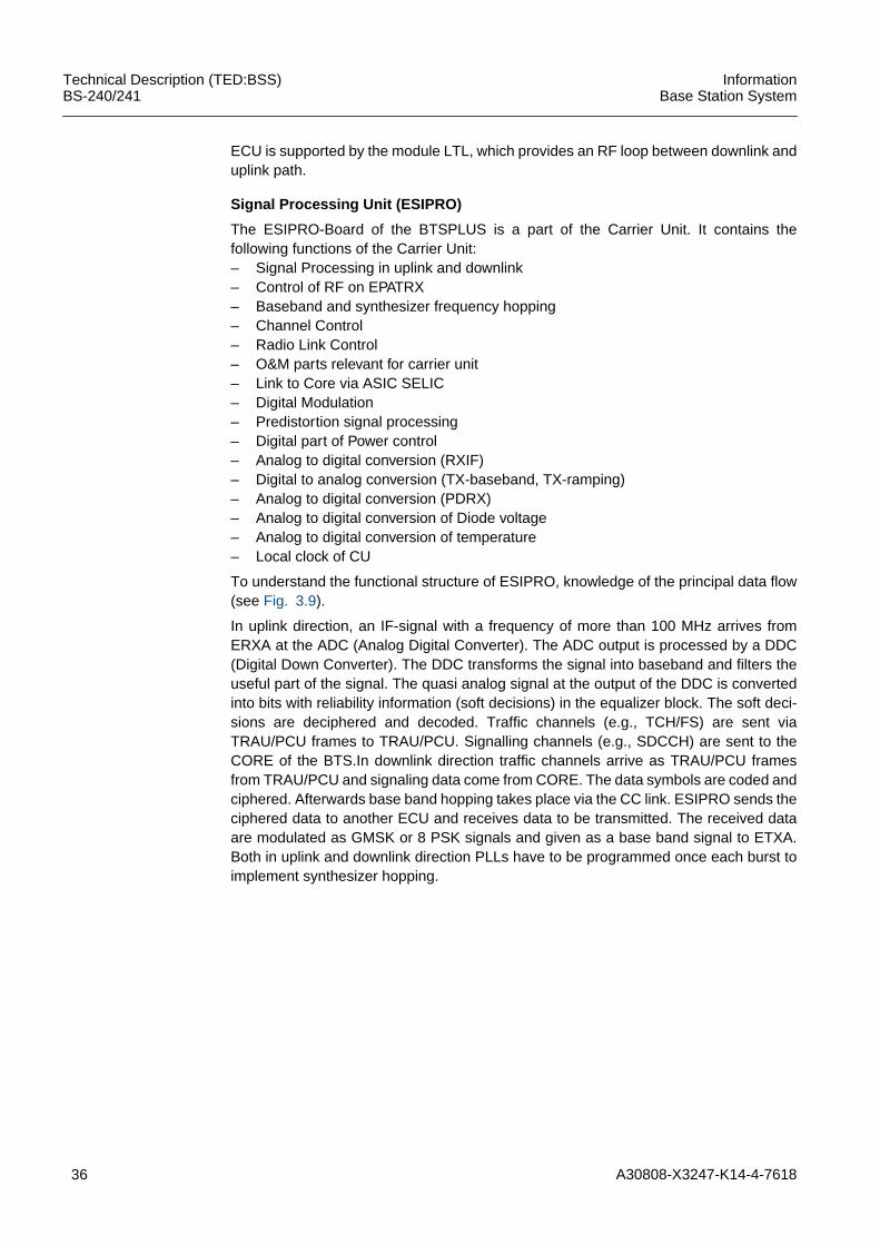
To understand the functional structure of ESIPRO, knowledge of the principal data flow(see Fig. 3.9).
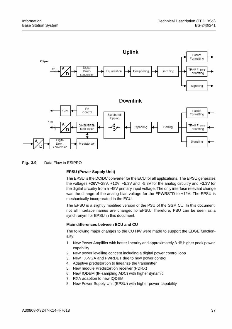
In uplink direction, an IF-signal with a frequency of more than 100 MHz arrives fromERXA at the ADC (Analog Digital Converter). The ADC output is processed by a DDC(Digital Down Converter). The DDC transforms the signal into baseband and filters theuseful part of the signal. The quasi analog signal at the output of the DDC is convertedinto bits with reliability information (soft decisions) in the equalizer block. The soft deci-sions are deciphered and decoded. Traffic channels (e.g., TCH/FS) are sent viaTRAU/PCU frames to TRAU/PCU. Signalling channels (e.g., SDCCH) are sent to theCORE of the BTS.In downlink direction traffic channels arrive as TRAU/PCU framesfrom TRAU/PCU and signaling data come from CORE. The data symbols are coded andciphered. Afterwards base band hopping takes place via the CC link. ESIPRO sends theciphered data to another ECU and receives data to be transmitted. The received dataare modulated as GMSK or 8 PSK signals and given as a base band signal to ETXA.Both in uplink and downlink direction PLLs have to be programmed once each burst toimplement synthesizer hopping.
A30808-X3247-K14-4-7618 37
InformationBase Station System
Technical Description (TED:BSS)BS-240/241
Fig. 3.9 Data Flow in ESIPRO
EPSU (Power Supply Unit)
The EPSU is the DC/DC converter for the ECU for all applications. The EPSU generatesthe voltages +26V/+28V, +12V, +5,3V and -5,3V for the analog circuitry and +3.3V forthe digital circuitry from a -48V primary input voltage. The only interface relevant changewas the change of the analog bias voltage for the EPWRSTD to +12V. The EPSU ismechanically incorporated in the ECU.
The EPSU is a slightly modified version of the PSU of the GSM CU. In this document,not all Interface names are changed to EPSU. Therefore, PSU can be seen as asynchronym for EPSU in this document.
Main differences between ECU and CU
The following major changes to the CU HW were made to support the EDGE function-ality:
1. New Power Amplifier with better linearity and approximately 3 dB higher peak powercapability
2. New power levelling concept including a digital power control loop3. New TX-VGA and PWRDET due to new power control4. Adaptive predistortion to linearize the transmitter5. New module Predistortion receiver (PDRX)6. New IQDEM (IF-sampling ADC) with higher dynamic7. RXA adaption to new IQDEM8. New Power Supply Unit (EPSU) with higher power capability
38 A30808-X3247-K14-4-7618
Technical Description (TED:BSS)BS-240/241
InformationBase Station System
3.4 Duplexer Amplifier Multi Coupler (DUAMCO)The DUAMCO consists of two identical modules. Every module contains a duplex filter,which combines the RX and the TX path together, to be fed to a common antenna. TheDUAMCO combines 1 (see Fig. 4.2), up to 2 (see Fig. 4.3) or up to 4 (see Fig. 4.4)carriers to one antenna and consists of two branches with the following elements:• a LNA (Low Noise Amplifier) which takes care of a low system noise figure• an attenuator (in case of installed TMAs, additional gains greater than the cable
losses must be adjusted by means of the attenuator)• a second low noise amplifier• a power splitter which distributes the received band to the CUs (Carrier Units)• a transmit path which consists of:
– an isolator which protects the PAs (Power Amplifiers) inside the CUs from eachother in order to assure the required intermodulation suppression
– a hybrid coupler which provides the reference signal for dynamic and static powercontrol. The corresponding not transmitted power is terminated in a load includinga heat sink (for DUAMCO 4:2 and DUAMCO 8:2)
– an ASU (Antenna Supervision Unit) which is responsible for detecting certainreflection factors at the antenna connector. The ASU detects the VSWR failureand generates a failure information towards the O&M (CAN bus interface). Thisinformation is subdivided in several levels with the following characteristics:- VSWR < 2 neither generation of warning nor of an alarm- 2 ≤ VSWR ≤ 3 generation of warning 'Antenna not Adjusted'- VSWR > 3 generation of VSWR alarm 'Antenna Faulty'.
and a common part consisting of:• a PDU (Power Distribution Unit) for two TMAs (Tower mounted Amplifier) connected
to the TMAs by means of an antenna feeder cable• an O&M interface which transmits error messages to the BTS core via a slow O&M
bus (CAN bus)
The DUAMCO amplifier has two different operation modes:– the AMCO mode where no TMA is used– in case a TMA is used the DUAMCO is configured in the MUCO mode
The PDU provides the DC power supply and the alarm supervision of the TMAs. Alarmmonitoring is done with a signalling interface between DUAMCO and TMA, modulatedonto a IF carrier at 7.86 MHz.
3.5 DI(=2) Amplifier Multi Coupler (DIAMCO)For the uplink direction, the DIAMCO is used to filter and distribute the received signalsto the Carrier Units in one Rack. The DIAMCO consists of two branches constituted by:– a receive filter– a low noise amplifier (LNA) which takes care of a low system noise figure– an attenuator– a second low noise amplifier– a power splitter which distributes the received band to the CUs (Carrier Units)
and a common part constituted by:– a PDU (Power Distribution Unit) for two TMAs (Tower mounted Amplifier) connected
to the TMAs by means of an antenna feeder cable– an O&M interface which transmits error messages to the BTS core via a slow O&M
bus (CAN bus)
A30808-X3247-K14-4-7618 39
InformationBase Station System
Technical Description (TED:BSS)BS-240/241
The DIAMCO RX amplifier has two different operation modes:– the AMCO mode where no TMA is used– in case a TMA is used the DIAMCO is configured in the MUCO mode
3.6 Filter Combiner (FICOM)With the FICOM, it is possible to combine up to 8 frequencies in downlink direction (TX)in one Rack. For the uplink direction (RX), the DIAMCO has to be used to filter anddistribute the received signals to the Carrier Units. The FICOM consists of remotetunable narrowband filters (TNF). The advantage of this filter combining technique is thevery low insertion loss, if e.g., 8 transmitters are combined to one antenna.
In principle, the FICOM offers the following functions:• RF Functions:
– RF Power Combining– Transmitter Spurious Signal Suppression– Isolation between inputs– Isolation output to input
• Control / Monitoring Functions:– Antenna VSWR alarm thresholds setting and status reporting– Internal Performance Monitoring– Interfacing with BTSE
• LED Display:– Antenna VSWR alarms– Tuning alarms– Presence of DC
• Lightning Protection at the RF output connector (7/16)
3.7 Tower Mounted Amplifier (TMA)The TMA connects the antenna with the BTSE in order to amplify the receive signal andpass through the transmit signal. The TMA contains two duplex filters, each on one RFconnector, to separate and combine the receive and transmit path inside the TMA. TheTMA consists of:– the RX parts of the duplex filter and– the LNA (Low Noise Amplifier) which takes care of a low system noise figure of the
RX part– the TX parts of the duplex filter
The DC power for the TMA is feed into the triplexer by the PDU (Power Distribution Unit)functionality of the DUAMCO/DIAMCO.
The Encoder/Decoder units of the TMA signalling interface generate an alarm for eachTMA separately by supervising the DC current consumption of each unit.
Note: When the TMA is used the DUAMCO/DIAMCO works in the so called MUCO(multi coupler) mode. In the MUCO mode, the DUAMCO/DIAMCO mainly works as multicoupler to split the receive signal for the following CUs.
3.8 High Power Duplexer Unit (HPDU)The High Power Duplexer has the task of combining the TX- and the RX-path into oneantenna, in order to minimize the number of antennas when FICOM is used. The HPDU
40 A30808-X3247-K14-4-7618
Technical Description (TED:BSS)BS-240/241
InformationBase Station System
contains a duplex filter for the transmit frequency band and for the receive frequencyband, but no Low Noise Amplifier in the RX path.
If the TMA shall be used together with a HPDU a so called BIAS-T (DUBIAS) forpowering and signalling of the TMA is required. Up to two HPDU can be integrated ontop of the Rack below the cover and also up to two HPDU could be fit in the gap betweenthe inner side wall and the Frame in the Shelter.
Note: HPDU is available for working in the P-GSM 900, GSM 1800 and GSM-PS 900.
3.9 DC Panel (DCP)The DC Panel contains the circuit breakers to protect the DC power lines for themodules, the ACTP, FAN units, HEX, LE units and the ACTC where the Rack/Shelteralarms will be connected. The temperature sensor is integrated in the ACTC. The frontpanel of the DC Panel for the Base Rack or shelter carries the connector for the LocalMaintenance Terminal (LMT).
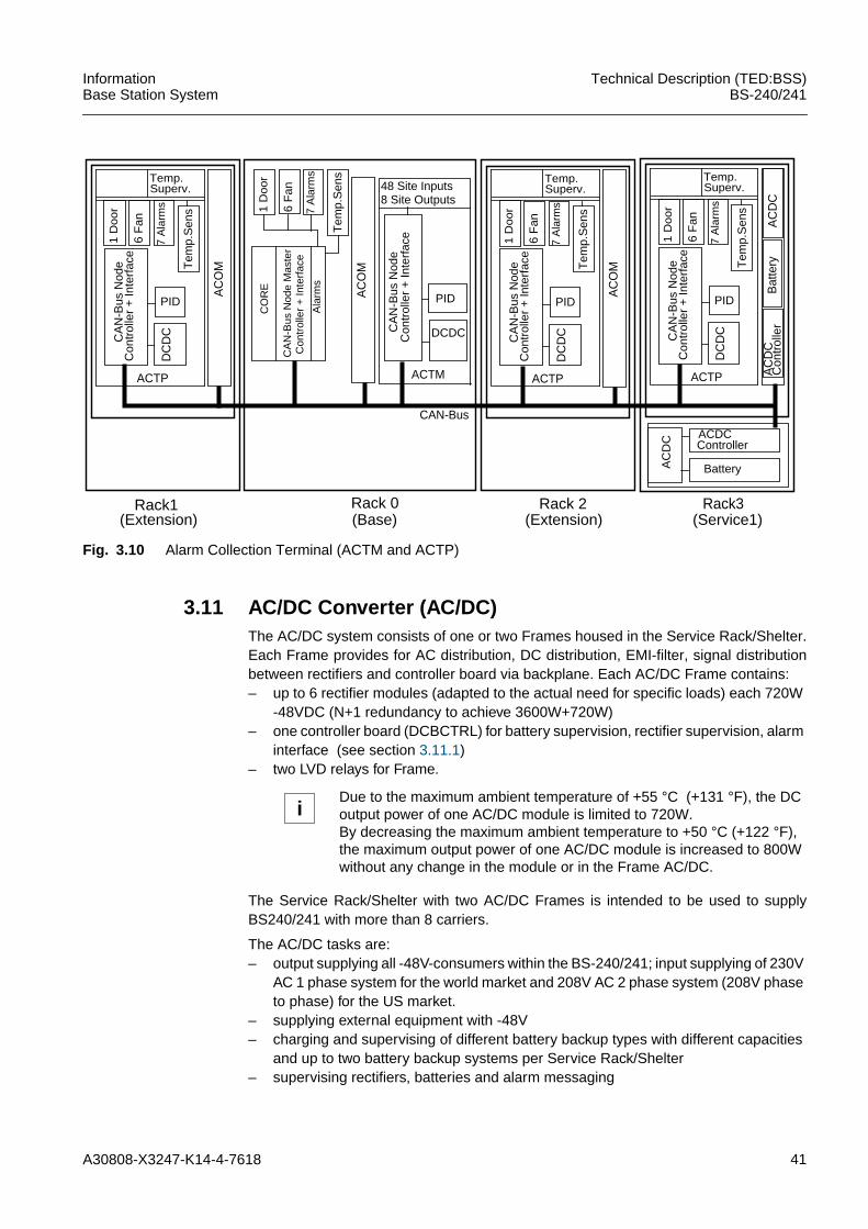
3.10 Alarm Collection Terminal (ACT)The Alarm Collection Terminal contains the interface to the external alarms (Operatoralarms, Rack alarms, shelter alarms,...) and commands and a CAN-BUS interface to theCORE.
ACTC is part of the DC-Panel and therefore it is installed once in every Rack/Shelter tocollect all internal alarms. It has inputs for 16 internal alarms (1 Door, 6 Fans and 9Rack/Shelter, internal alarms, which can be defined by the operator). In the BaseRack/Shelter the ACTC is direct connected to the COBA. In all other Racks/Shelters, theACTC is connected to the ACTP.
The ACTM and ACTP contain their own DC/DC converter on board, a controller, inter-faces towards the CAN-Bus and an alarm interface for 16 Rack/Shelter alarms or siteinputs. ACTM has an additional interface for Operator Alarms (48 site inputs). ACTMand ACTP have a DIP Switch device to set the Rack address.
The tasks of the ACT are:– Collection of all alarms for units having no access to O&M BUS to CORE.– Collection of so-called cabinet specific alarms (Rack, Shelter).– Collection of so-called operator available alarms (Site Inputs).– Distribution of operator available commands (Site Outputs).– 8 bit µC (80C505C) for initialization, supervision and controlling the functions of the
ACT.– PID-EEPROM to store board data.
The physical function of the ACT is to interface the alarm and command signals betweenthe CAN-BUS and the alarm and command connectors. The ACT is designed to be usedonly one time for the Rack. So the ACT is an element without redundancy, but the BTSEis not out of service in case of a faulty ACT.
Different ACT, are available depending on the applications in the Base Rack/Shelter(ACTM) or in the Service and Extension Rack/Shelter (ACTP) as shown in Fig. 3.10.
A30808-X3247-K14-4-7618 41
InformationBase Station System
Technical Description (TED:BSS)BS-240/241
Fig. 3.10 Alarm Collection Terminal (ACTM and ACTP)
3.11 AC/DC Converter (AC/DC)The AC/DC system consists of one or two Frames housed in the Service Rack/Shelter.Each Frame provides for AC distribution, DC distribution, EMI-filter, signal distributionbetween rectifiers and controller board via backplane. Each AC/DC Frame contains:– up to 6 rectifier modules (adapted to the actual need for specific loads) each 720W
-48VDC (N+1 redundancy to achieve 3600W+720W)– one controller board (DCBCTRL) for battery supervision, rectifier supervision, alarm
interface (see section 3.11.1)– two LVD relays for Frame.
The Service Rack/Shelter with two AC/DC Frames is intended to be used to supplyBS240/241 with more than 8 carriers.
The AC/DC tasks are:– output supplying all -48V-consumers within the BS-240/241; input supplying of 230V
AC 1 phase system for the world market and 208V AC 2 phase system (208V phaseto phase) for the US market.
– supplying external equipment with -48V– charging and supervising of different battery backup types with different capacities
and up to two battery backup systems per Service Rack/Shelter– supervising rectifiers, batteries and alarm messaging
1 D
oor
6 F
an
7 A
larm
s
Tem
p.S
ens
CA
N-B
us N
ode
Con
trol
ler
+ In
terf
ace
PID
DC
DC
Rack1(Extension)
ACDCController
BatteryAC
DC
CO
RE
CA
N-B
us N
ode
Mas
ter
Con
trol
ler
+ In
terf
ace
Ala
rms
Temp.Superv.
AC
OM
ACTP
1 D
oo
r
6 F
an
7 A
larm
s
Tem
p.S
ens
CA
N-B
us N
ode
Con
trol
ler
+ In
terf
ace
PIDAC
OM
ACTM
48 Site Inputs8 Site Outputs
DCDC
1 D
oo
r
6 F
an
7 A
larm
s
Tem
p.S
ens
CA
N-B
us N
ode
Con
trol
ler
+ In
terf
ace
PID
DC
DC
Rack 2(Extension)
Temp.Superv.
AC
OM
ACTP
1 D
oo
r
6 F
an
7 A
larm
s
Tem
p.S
ens
CA
N-B
us N
ode
Con
trol
ler
+ In
terf
ace
PID
DC
DC
Temp.Superv.
AC
DC
ACTP
Bat
tery
AC
DC
Con
trol
ler
Rack3(Service1)
Rack 0(Base)
CAN-Bus
iDue to the maximum ambient temperature of +55 °C (+131 °F), the DCoutput power of one AC/DC module is limited to 720W.By decreasing the maximum ambient temperature to +50 °C (+122 °F),the maximum output power of one AC/DC module is increased to 800Wwithout any change in the module or in the Frame AC/DC.
42 A30808-X3247-K14-4-7618
Technical Description (TED:BSS)BS-240/241
InformationBase Station System
– switching off DC outputs (rectifiers as well as battery) in case of under and overtemperature
– hot plug in/out– operation of two Frames in parallel
The AC/DC and the backup batteries work as an Uninterruptable Power Supply System(UPS).
3.11.1 DC and Battery Controller (DCBCTRL)The DC and Battery Controller is the supervision unit for the AC/DC Converters installedin the Frame AC/DC and for the Batteries charging of this set of AC/DCs. The DCBCTRLhas a dip switch device to adjust the frame address AC/DC frame 1 or AC/DC frame 2and the battery capacities of the connected battery system.
3.12 Overvoltage Protection and Tracer (OVPT)The OVPT is responsible for coarse protection of the PCM24/PCM30 ports of the Abisinterface and the external synchronization clock input of the BS-240/241 against overvoltage. Additionally, the OVPT provides interfaces to connect PCM tracers withoutinterruption for monitoring the Abis lines. The OVPT is located outside the EMI shield inorder to terminate possible overvoltages before it enters the EMI protected area insidethe Rack.
The board performs the following tasks:– lightning protection of PCM lines– lightning protection of the ext. synchronisation clock– provision to connect ext. monitoring equipment without interruption. The lines are
de-coupled by resistors in order to prevent distortions.– supporting 75 Ω coax and 100 Ω/120 Ω symmetrical lines– for 75 Ω coax only a second version of the OVPT is available– provides grounding facility for the external cable shielding– provides stress relieve for the external cables
3.13 Abis Link Equipment (LE)The link equipment acts as front end to provide the Abis interface. Different equipmentcan be used for wire or radio transmission depending on customer requirements. If a linkequipment is available at the telecommunication site, possibly no link equipment isnecessary. If BS-240/241 is installed away from a telecommunication site the link equip-ment must be installed inside the Service Rack/Shelter. If radio transmission is required,microwave equipment must be used. Also direct connections of PCM24/30 links arepossible. The number of Link Equipment, which can be installed, depends on the heightof the Link Equipment.
3.14 Cover PartsAll unequipped slots in the Frames of a Rack/Shelter must be equipped with CoverParts, to reach a balanced airflow. If all slots of a Frame are not equipped with modulesit is not necessary to cover all the empty slots.
A30808-X3247-K14-4-7618 43
InformationBase Station System
Technical Description (TED:BSS)BS-240/241
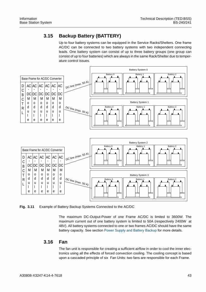
3.15 Backup Battery (BATTERY)Up to four battery systems can be equipped in the Service Racks/Shelters. One frameAC/DC can be connected to two battery systems with two independent connectingleads. One battery system can consist of up to three battery groups (one group canconsist of up to four batteries) which are always in the same Rack/Shelter due to temper-ature control issues.
Fig. 3.11 Example of Battery Backup Systems Connected to the AC/DC
The maximum DC-Output-Power of one Frame AC/DC is limited to 3600W. Themaximum current out of one battery system is limited to 50A (respectively 2400W at48V). All battery systems connected to one or two frames AC/DC should have the samebattery capacity. See section Power Supply and Battery Backup for more details.
3.16 FanThe fan unit is responsible for creating a sufficient airflow in order to cool the inner elec-tronics using all the effects of forced convection cooling. The cooling concept is basedupon a cascaded principle of six Fan Units: two fans are responsible for each Frame.
Battery 0
Base Frame for AC/DC Converter
DCBCTRL
AC
DC-
AC
DC-
AC
DC-
AC
DC-
AC
DC-
AC
DC-
Battery System 0
DC line (max. 50 A)
DC line (max. 50 A)
Battery System 1
Battery System 2
DC line (max. 50 A)
DC line (max. 50 A)
Battery System 3
Battery 1 Battery 2
Battery 0 Battery 1 Battery 2
Battery 0 Battery 1 Battery 2
Battery 0 Battery 1 Battery 2
Module
Module
Module
Module
Module
Module
Base Frame for AC/DC Converter
DCBCTRL
AC
DC-
AC
DC-
AC
DC-
AC
DC-
AC
DC-
AC
DC-
Module
Module
Module
Module
Module
Module
44 A30808-X3247-K14-4-7618
Technical Description (TED:BSS)BS-240/241
InformationBase Station System
The fans used are able to overcome the pressure drop caused by the system resistancetaking into account additional losses caused by adequate filters or Heat Exchangersused in order to establish an airflow that limits the ∆T (Temperature difference betweencritical hotspots inside the Rack and the ambient temperature) caused by the specificpower dissipation of that hotspot.
In order to keep both the acoustic noise and the power consumption of all fans at thelowest level possible, the fan speeds are (independently of each other) temperaturecontrolled via integrated sensors (NTC) that monitor the critical hotspots in order to keepthem in an acceptable range.
Furthermore, each fan delivers a fan good/fan bad signal that is processed by the COBAboard (routed via ACTC board in case of a Base Rack/Shelter or the ACTC board andCAN Bus in case of an Extension-/Service Rack/Shelter).
3.17Heat Exchanger (HEX)The BS-241 shelters can be equipped either with HEX.The heat exchangers can only be equipped on the internal side of the door of the BS-241shelter. The task of a heat exchanger is to transport the heat from inside the shelter tothe outside.
For every Frame in a base or extension shelter one heat exchanger is needed, there-fore, 3 heatexchangers are always installed in a base or extension shelter for:– ACOM Frame– Carrier Frame– Core Frame
In the service shelter we have three sections, which can be differently equipped withAC/DC modules, link equipment or backup batteries and then 1 to 3 heat exchangersare needed, according to the installation of equipment.
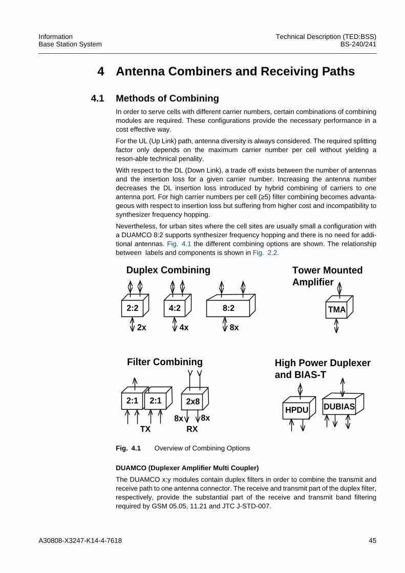
A30808-X3247-K14-4-7618 45
InformationBase Station System
Technical Description (TED:BSS)BS-240/241
4 Antenna Combiners and Receiving Paths
4.1 Methods of CombiningIn order to serve cells with different carrier numbers, certain combinations of combiningmodules are required. These configurations provide the necessary performance in acost effective way.
For the UL (Up Link) path, antenna diversity is always considered. The required splittingfactor only depends on the maximum carrier number per cell without yielding areson-able technical penality.
With respect to the DL (Down Link), a trade off exists between the number of antennasand the insertion loss for a given carrier number. Increasing the antenna numberdecreases the DL insertion loss introduced by hybrid combining of carriers to oneantenna port. For high carrier numbers per cell (≥5) filter combining becomes advanta-geous with respect to insertion loss but suffering from higher cost and incompatibility tosynthesizer frequency hopping.
Nevertheless, for urban sites where the cell sites are usually small a configuration witha DUAMCO 8:2 supports synthesizer frequency hopping and there is no need for addi-tional antennas. Fig. 4.1 the different combining options are shown. The relationshipbetween labels and components is shown in Fig. 2.2.
Fig. 4.1 Overview of Combining Options
DUAMCO (Duplexer Amplifier Multi Coupler)
The DUAMCO x:y modules contain duplex filters in order to combine the transmit andreceive path to one antenna connector. The receive and transmit part of the duplex filter,respectively, provide the substantial part of the receive and transmit band filteringrequired by GSM 05.05, 11.21 and JTC J-STD-007.
2:2
2x
4:2
4x
8:2
8x
TMA
Tower Mounted
2:1
RX
High Power Duplexer
Duplex Combining
Filter Combining
HPDU2:1
TX8x 8x
2x8DUBIAS
and BIAS-T
Amplifier
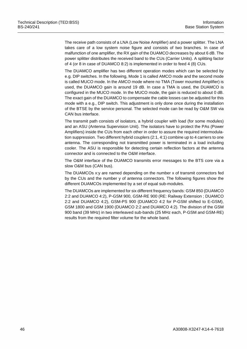
46 A30808-X3247-K14-4-7618
Technical Description (TED:BSS)BS-240/241
InformationBase Station System
The receive path consists of a LNA (Low Noise Amplifier) and a power splitter. The LNAtakes care of a low system noise figure and consists of two branches. In case ofmalfunction of one amplifier, the RX gain of the DUAMCO decreases by about 6 dB. Thepower splitter distributes the received band to the CUs (Carrier Units). A splitting factorof 4 (or 8 in case of DUAMCO 8:2) is implemented in order to feed 4 (8) CUs.
The DUAMCO amplifier has two different operation modes which can be selected bye.g. DIP switches. In the following, Mode 1 is called AMCO mode and the second modeis called MUCO mode. In the AMCO mode where no TMA (Tower mounted Amplifier) isused, the DUAMCO gain is around 19 dB. In case a TMA is used, the DUAMCO isconfigured in the MUCO mode. In the MUCO mode, the gain is reduced to about 0 dB.The exact gain of the DUAMCO to compensate the cable losses can be adjusted for thismode with a e.g., DIP switch. This adjustment is only done once during the installationof the BTSE by the service personal. The selected mode can be read by O&M SW viaCAN bus interface.
The transmit path consists of isolators, a hybrid coupler with load (for some modules)and an ASU (Antenna Supervision Unit). The isolators have to protect the PAs (PowerAmplifiers) inside the CUs from each other in order to assure the required intermodula-tion suppression. Two different hybrid couplers (2:1, 4:1) combine up to 4 carriers to oneantenna. The corresponding not transmitted power is terminated in a load includingcooler. The ASU is responsible for detecting certain reflection factors at the antennaconnector and is connected to the O&M interface.
The O&M interface of the DUAMCO transmits error messages to the BTS core via aslow O&M bus (CAN bus).
The DUAMCOs x:y are named depending on the number x of transmit connectors fedby the CUs and the number y of antenna connectors. The following figures show thedifferent DUAMCOs implemented by a set of equal sub-modules.
The DUAMCOs are implemented for six different frequency bands: GSM 850 (DUAMCO2:2 and DUAMCO 4:2), P-GSM 900, GSM-RE 900 (RE: Railway Extension ; DUAMCO2:2 and DUAMCO 4:2), GSM-PS 900 (DUAMCO 4:2 for P-GSM shifted to E-GSM),GSM 1800 and GSM 1900 (DUAMCO 2:2 and DUAMCO 4:2). The division of the GSM900 band (39 MHz) in two interleaved sub-bands (25 MHz each, P-GSM and GSM-RE)results from the required filter volume for the whole band.
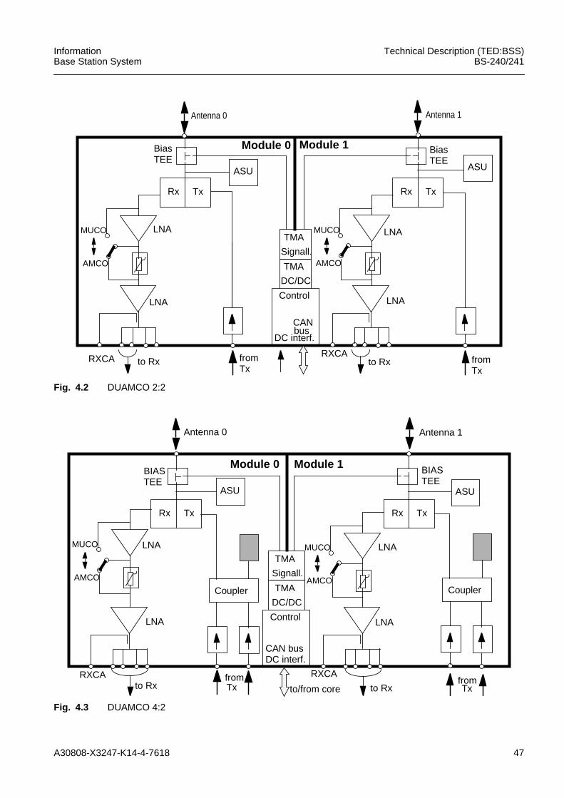
A30808-X3247-K14-4-7618 47
InformationBase Station System
Technical Description (TED:BSS)BS-240/241
Fig. 4.2 DUAMCO 2:2
Fig. 4.3 DUAMCO 4:2
Rx Tx
ASU
LNA
RXCA to Rx fromTx
Control
CAN
DC interf.
TMA
DC/DC
TMA
Signall.
Rx Tx
ASU
LNA
RXCAto Rx from
Tx
AMCO
MUCO
AMCO
MUCO
LNALNA
bus
BiasTEE
BiasTEE
Module 0 Module 1
Antenna 0 Antenna 1
Antenna 0
Rx Tx
ASU
LNA
RXCAto Rx
fromTx
Control
CAN busDC interf.
TMA
DC/DC
TMA
Signall.
Rx Tx
LNA
RXCA
to RxfromTx
Antenna 1
Coupler
to/from core
ASU
CouplerAMCO
MUCO
AMCO
MUCO
LNA LNA
BIASTEE
BIASTEE
Module 0 Module 1
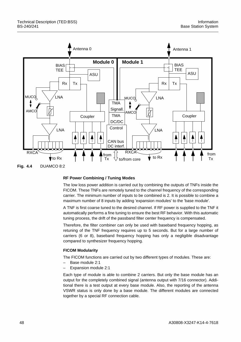
48 A30808-X3247-K14-4-7618
Technical Description (TED:BSS)BS-240/241
InformationBase Station System
Fig. 4.4 DUAMCO 8:2
RF Power Combining / Tuning Modes
The low loss power addition is carried out by combining the outputs of TNFs inside theFICOM. These TNFs are remotely tuned to the channel frequency of the correspondingcarrier. The minimum number of inputs to be combined is 2. It is possible to combine amaximum number of 8 inputs by adding 'expansion modules' to the 'base module'.
A TNF is first coarse tuned to the desired channel. If RF power is supplied to the TNF itautomatically performs a fine tuning to ensure the best RF behavior. With this automatictuning process, the drift of the passband filter center frequency is compensated.
Therefore, the filter combiner can only be used with baseband frequency hopping, asretuning of the TNF frequency requires up to 5 seconds. But for a large number ofcarriers (6 or 8), baseband frequency hopping has only a negligible disadvantagecompared to synthesizer frequency hopping.
FICOM Modularity
The FICOM functions are carried out by two different types of modules. These are:– Base module 2:1– Expansion module 2:1
Each type of module is able to combine 2 carriers. But only the base module has anoutput for the completely combined signal (antenna output with 7/16 connector). Addi-tional there is a test output at every base module. Also, the reporting of the antennaVSWR status is only done by a base module. The different modules are connectedtogether by a special RF connection cable.
Rx Tx
ASU
LNA
RXCAto Rx
fromTx
Control
CAN busDC interf.
TMA
DC/DC
TMA
Signall.
Rx Tx
LNA
RXCAto Rx
fromTx
Coupler
to/from core
ASU
CouplerAMCO
MUCO
AMCO
MUCO
LNA LNA
BIASTEE
BIASTEE
Module 0 Module 1
Antenna 0 Antenna 1
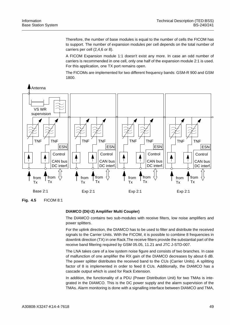
A30808-X3247-K14-4-7618 49
InformationBase Station System
Technical Description (TED:BSS)BS-240/241
Therefore, the number of base modules is equal to the number of cells the FICOM hasto support. The number of expansion modules per cell depends on the total number ofcarriers per cell (2,4,6 or 8).
A FICOM Expansion module 1:1 doesn't exist any more. In case an odd number ofcarriers is recommended in one cell, only one half of the expansion module 2:1 is used.For this application, one TX port remains open.
The FICOMs are implemented for two different frequency bands: GSM-R 900 and GSM1800.
Fig. 4.5 FICOM 8:1
DIAMCO (DI(=2) Amplifier Multi Coupler)
The DIAMCO contains two sub-modules with receive filters, low noise amplifiers andpower splitters.
For the uplink direction, the DIAMCO has to be used to filter and distribute the receivedsignals to the Carrier Units. With the FICOM, it is possible to combine 8 frequencies indownlink direction (TX) in one Rack.The receive filters provide the substantial part of thereceive band filtering required by GSM 05.05, 11.21 and JTC J-STD-007.
The LNA takes care of a low system noise figure and consists of two branches. In caseof malfunction of one amplifier the RX gain of the DIAMCO decreases by about 6 dB.The power splitter distributes the received band to the CUs (Carrier Units). A splittingfactor of 8 is implemented in order to feed 8 CUs. Additionally, the DIAMCO has acascade output which is used for Rack Extension.
In addition, the functionality of a PDU (Power Distribution Unit) for two TMAs is inte-grated in the DIAMCO. This is the DC power supply and the alarm supervision of theTMAs. Alarm monitoring is done with a signalling interface between DIAMCO and TMA,
TNF TNF
ESN
Control
CAN busDC interf.
VS WRsupervision
Antenna
fromTx
fromTx
TNF TNF
ESN
Control
CAN busDC interf.
fromTx
fromTx
TNF TNF
ESN
Control
CAN busDC interf.
fromTx
fromTx
TNF TNF
ESN
Control
CAN busDC interf.
fromTx
fromTx
Base 2:1 Exp 2:1 Exp 2:1 Exp 2:1
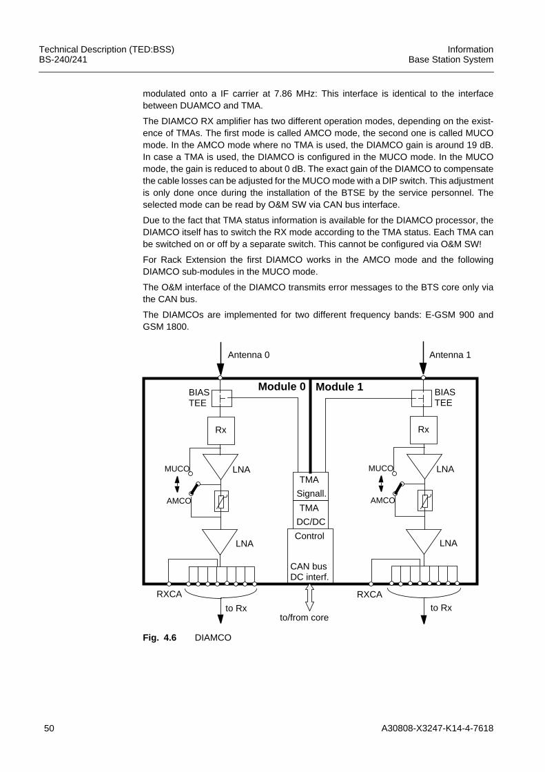
50 A30808-X3247-K14-4-7618
Technical Description (TED:BSS)BS-240/241
InformationBase Station System
modulated onto a IF carrier at 7.86 MHz: This interface is identical to the interfacebetween DUAMCO and TMA.
The DIAMCO RX amplifier has two different operation modes, depending on the exist-ence of TMAs. The first mode is called AMCO mode, the second one is called MUCOmode. In the AMCO mode where no TMA is used, the DIAMCO gain is around 19 dB.In case a TMA is used, the DIAMCO is configured in the MUCO mode. In the MUCOmode, the gain is reduced to about 0 dB. The exact gain of the DIAMCO to compensatethe cable losses can be adjusted for the MUCO mode with a DIP switch. This adjustmentis only done once during the installation of the BTSE by the service personnel. Theselected mode can be read by O&M SW via CAN bus interface.
Due to the fact that TMA status information is available for the DIAMCO processor, theDIAMCO itself has to switch the RX mode according to the TMA status. Each TMA canbe switched on or off by a separate switch. This cannot be configured via O&M SW!
For Rack Extension the first DIAMCO works in the AMCO mode and the followingDIAMCO sub-modules in the MUCO mode.
The O&M interface of the DIAMCO transmits error messages to the BTS core only viathe CAN bus.
The DIAMCOs are implemented for two different frequency bands: E-GSM 900 andGSM 1800.
Fig. 4.6 DIAMCO
Antenna 0
Rx
RXCA
to Rx
Control
CAN busDC interf.
TMA
DC/DC
TMA
Signall.
Antenna 1
to/from core
Rx
RXCA
to Rx
LNA
AMCO
MUCO
LNA
LNA
AMCO
MUCO
LNA
BIASTEE
BIASTEE
Module 0 Module 1
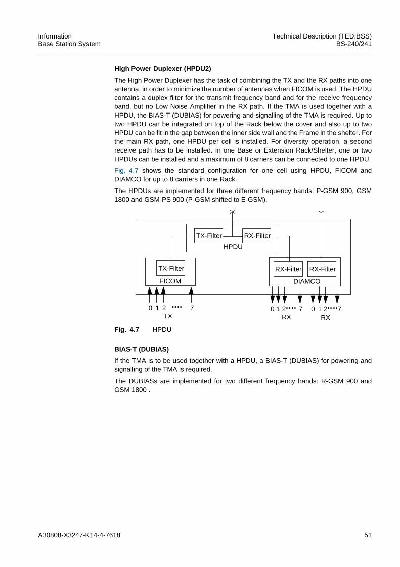
A30808-X3247-K14-4-7618 51
InformationBase Station System
Technical Description (TED:BSS)BS-240/241
High Power Duplexer (HPDU2)
The High Power Duplexer has the task of combining the TX and the RX paths into oneantenna, in order to minimize the number of antennas when FICOM is used. The HPDUcontains a duplex filter for the transmit frequency band and for the receive frequencyband, but no Low Noise Amplifier in the RX path. If the TMA is used together with aHPDU, the BIAS-T (DUBIAS) for powering and signalling of the TMA is required. Up totwo HPDU can be integrated on top of the Rack below the cover and also up to twoHPDU can be fit in the gap between the inner side wall and the Frame in the shelter. Forthe main RX path, one HPDU per cell is installed. For diversity operation, a secondreceive path has to be installed. In one Base or Extension Rack/Shelter, one or twoHPDUs can be installed and a maximum of 8 carriers can be connected to one HPDU.
Fig. 4.7 shows the standard configuration for one cell using HPDU, FICOM andDIAMCO for up to 8 carriers in one Rack.
The HPDUs are implemented for three different frequency bands: P-GSM 900, GSM1800 and GSM-PS 900 (P-GSM shifted to E-GSM).
Fig. 4.7 HPDU
BIAS-T (DUBIAS)
If the TMA is to be used together with a HPDU, a BIAS-T (DUBIAS) for powering andsignalling of the TMA is required.
The DUBIASs are implemented for two different frequency bands: R-GSM 900 andGSM 1800 .
FICOM
TX-Filter
TX-Filter RX-Filter
HPDU
DIAMCO
RX-Filter RX-Filter
0 1 2 7TX
0 1 2 7RX
0 1 2 7RX
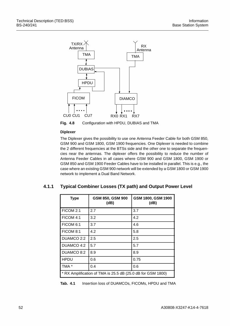
52 A30808-X3247-K14-4-7618
Technical Description (TED:BSS)BS-240/241
InformationBase Station System
Fig. 4.8 Configuration with HPDU, DUBIAS and TMA
Diplexer
The Diplexer gives the possibility to use one Antenna Feeder Cable for both GSM 850,GSM 900 and GSM 1800, GSM 1900 frequencies. One Diplexer is needed to combinethe 2 different frequencies at the BTSs side and the other one to separate the frequen-cies near the antennas. The diplexer offers the possibility to reduce the number ofAntenna Feeder Cables in all cases where GSM 900 and GSM 1800, GSM 1900 orGSM 850 and GSM 1900 Feeder Cables have to be installed in parallel. This is e.g., thecase where an existing GSM 900 network will be extended by a GSM 1800 or GSM 1900network to implement a Dual Band Network.
4.1.1 Typical Combiner Losses (TX path) and Output Power Level
TMA TMA
DUBIAS
HPDU
TX/RX RX
FICOM
CU0 CU1 CU7
DIAMCO
RX0 RX1 RX7
Antenna Antenna
Type GSM 850, GSM 900(dB)
GSM 1800, GSM 1900(dB)
FICOM 2:1 2.7 3.7
FICOM 4:1 3.2 4.2
FICOM 6:1 3.7 4.6
FICOM 8:1 4.2 5.8
DUAMCO 2:2 2.5 2.5
DUAMCO 4:2 5.7 5.7
DUAMCO 8:2 8.9 8.9
HPDU 0.6 0.75
TMA * 0.4 0.6
* RX Amplification of TMA is 25.5 dB (25.0 dB for GSM 1800)
Tab. 4.1 Insertion loss of DUAMCOs, FICOMs, HPDU and TMA
A30808-X3247-K14-4-7618 53
InformationBase Station System
Technical Description (TED:BSS)BS-240/241
iDUAMCOs operating with the minimum guaranteed input power from CU:GSM 850, GSM 900: n x 50 W; GSM 1800, GSM 1900: n x 35 W
iThe typical value for the insertion loss of FICOMs is better than 3 dB with an uncriticalcarrier configuration (carrier spacing > 1 MHz).
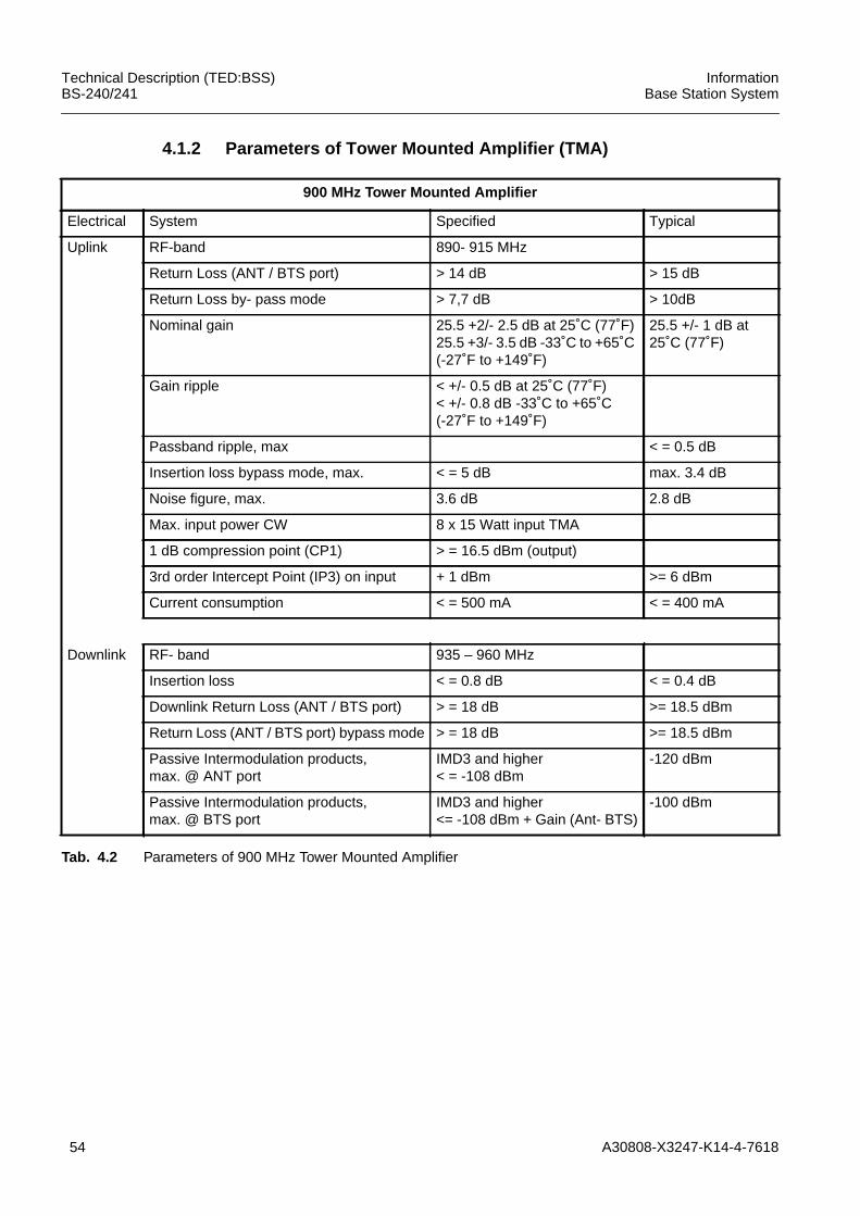
54 A30808-X3247-K14-4-7618
Technical Description (TED:BSS)BS-240/241
InformationBase Station System
4.1.2 Parameters of Tower Mounted Amplifier (TMA)
900 MHz Tower Mounted Amplifier
Electrical System Specified Typical
Uplink RF-band 890- 915 MHz
Return Loss (ANT / BTS port) > 14 dB > 15 dB
Return Loss by- pass mode > 7,7 dB > 10dB
Nominal gain 25.5 +2/- 2.5 dB at 25˚C (77˚F)25.5 +3/- 3.5 dB -33˚C to +65˚C(-27˚F to +149˚F)
25.5 +/- 1 dB at25˚C (77˚F)
Gain ripple < +/- 0.5 dB at 25˚C (77˚F)< +/- 0.8 dB -33˚C to +65˚C(-27˚F to +149˚F)
Passband ripple, max < = 0.5 dB
Insertion loss bypass mode, max. < = 5 dB max. 3.4 dB
Noise figure, max. 3.6 dB 2.8 dB
Max. input power CW 8 x 15 Watt input TMA
1 dB compression point (CP1) > = 16.5 dBm (output)
3rd order Intercept Point (IP3) on input + 1 dBm >= 6 dBm
Current consumption < = 500 mA < = 400 mA
Downlink RF- band 935 – 960 MHz
Insertion loss < = 0.8 dB < = 0.4 dB
Downlink Return Loss (ANT / BTS port) > = 18 dB >= 18.5 dBm
Return Loss (ANT / BTS port) bypass mode > = 18 dB >= 18.5 dBm
Passive Intermodulation products,max. @ ANT port
IMD3 and higher< = -108 dBm
-120 dBm
Passive Intermodulation products,max. @ BTS port
IMD3 and higher<= -108 dBm + Gain (Ant- BTS)
-100 dBm
Tab. 4.2 Parameters of 900 MHz Tower Mounted Amplifier
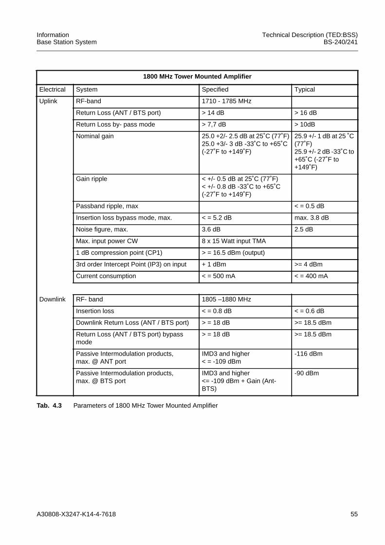
A30808-X3247-K14-4-7618 55
InformationBase Station System
Technical Description (TED:BSS)BS-240/241
1800 MHz Tower Mounted Amplifier
Electrical System Specified Typical
Uplink RF-band 1710 - 1785 MHz
Return Loss (ANT / BTS port) > 14 dB > 16 dB
Return Loss by- pass mode > 7,7 dB > 10dB
Nominal gain 25.0 +2/- 2.5 dB at 25˚C (77˚F)25.0 +3/- 3 dB -33˚C to +65˚C(-27˚F to +149˚F)
25.9 +/- 1 dB at 25 ˚C(77˚F)25.9 +/- 2 dB -33˚C to+65˚C (-27˚F to+149˚F)
Gain ripple < +/- 0.5 dB at 25˚C (77˚F)< +/- 0.8 dB -33˚C to +65˚C(-27˚F to +149˚F)
Passband ripple, max < = 0.5 dB
Insertion loss bypass mode, max. < = 5.2 dB max. 3.8 dB
Noise figure, max. 3.6 dB 2.5 dB
Max. input power CW 8 x 15 Watt input TMA
1 dB compression point (CP1) > = 16.5 dBm (output)
3rd order Intercept Point (IP3) on input + 1 dBm >= 4 dBm
Current consumption < = 500 mA < = 400 mA
Downlink RF- band 1805 –1880 MHz
Insertion loss < = 0.8 dB < = 0.6 dB
Downlink Return Loss (ANT / BTS port) > = 18 dB >= 18.5 dBm
Return Loss (ANT / BTS port) bypassmode
> = 18 dB >= 18.5 dBm
Passive Intermodulation products,max. @ ANT port
IMD3 and higher< = -109 dBm
-116 dBm
Passive Intermodulation products,max. @ BTS port
IMD3 and higher<= -109 dBm + Gain (Ant-BTS)
-90 dBm
Tab. 4.3 Parameters of 1800 MHz Tower Mounted Amplifier
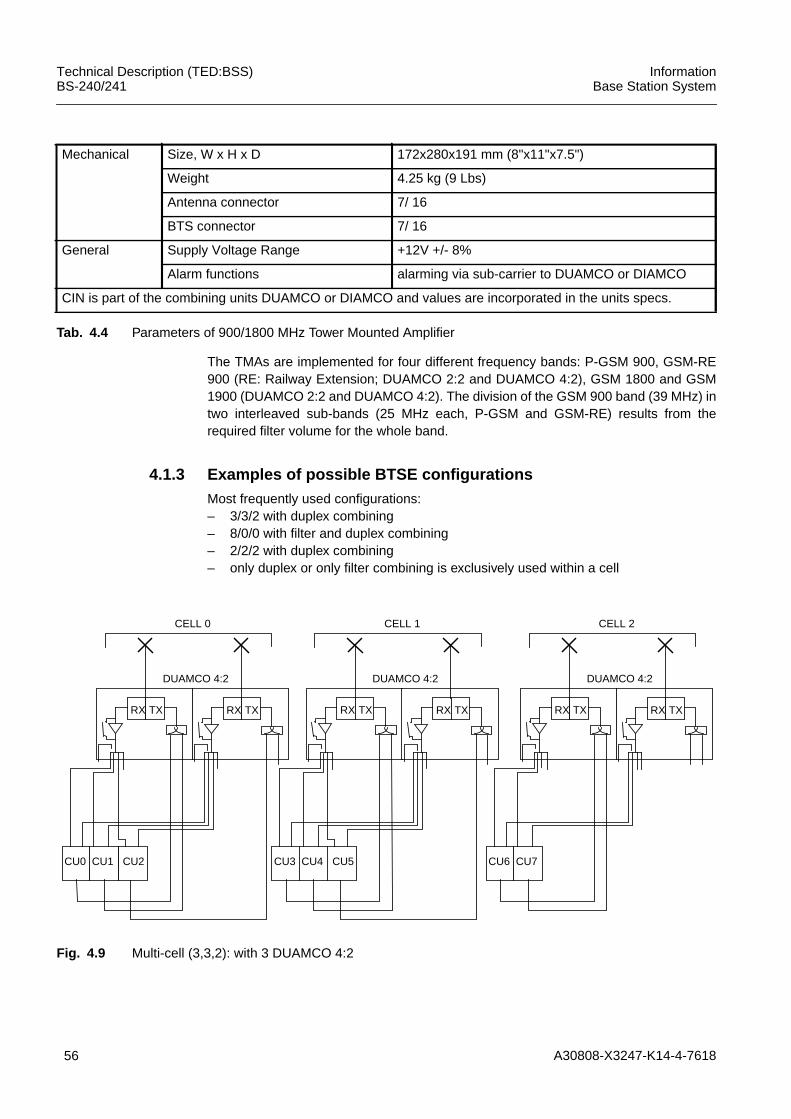
56 A30808-X3247-K14-4-7618
Technical Description (TED:BSS)BS-240/241
InformationBase Station System
The TMAs are implemented for four different frequency bands: P-GSM 900, GSM-RE900 (RE: Railway Extension; DUAMCO 2:2 and DUAMCO 4:2), GSM 1800 and GSM1900 (DUAMCO 2:2 and DUAMCO 4:2). The division of the GSM 900 band (39 MHz) intwo interleaved sub-bands (25 MHz each, P-GSM and GSM-RE) results from therequired filter volume for the whole band.
4.1.3 Examples of possible BTSE configurationsMost frequently used configurations:– 3/3/2 with duplex combining– 8/0/0 with filter and duplex combining– 2/2/2 with duplex combining– only duplex or only filter combining is exclusively used within a cell
Fig. 4.9 Multi-cell (3,3,2): with 3 DUAMCO 4:2
Mechanical Size, W x H x D 172x280x191 mm (8"x11"x7.5")
Weight 4.25 kg (9 Lbs)
Antenna connector 7/ 16
BTS connector 7/ 16
General Supply Voltage Range +12V +/- 8%
Alarm functions alarming via sub-carrier to DUAMCO or DIAMCO
CIN is part of the combining units DUAMCO or DIAMCO and values are incorporated in the units specs.
Tab. 4.4 Parameters of 900/1800 MHz Tower Mounted Amplifier
RX TX RX
DUAMCO 4:2
TX
CU2CU0 CU1
CELL 0
RX TX RX
DUAMCO 4:2
TX
CU6 CU7
CELL 2
RX TX RX
DUAMCO 4:2
TX
CU5CU3 CU4
CELL 1
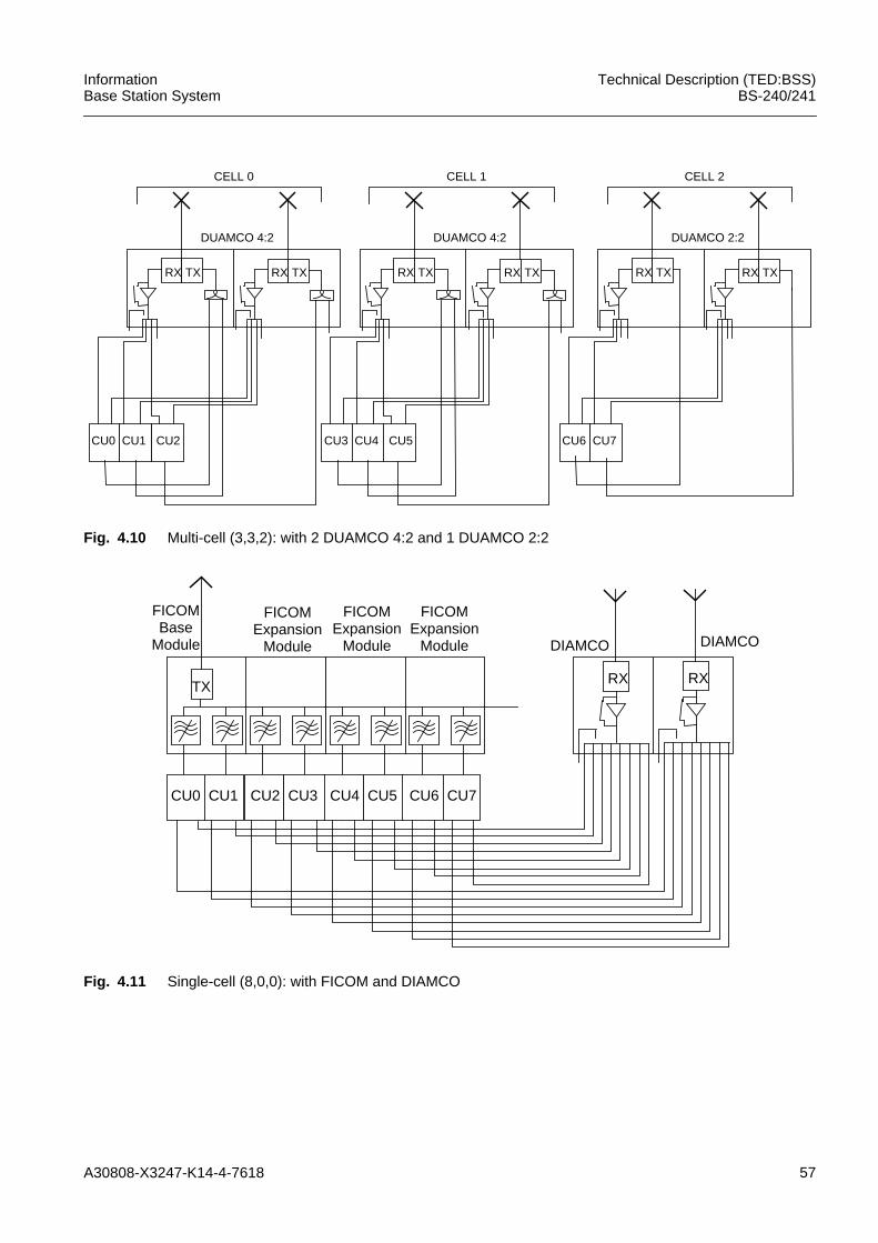
A30808-X3247-K14-4-7618 57
InformationBase Station System
Technical Description (TED:BSS)BS-240/241
Fig. 4.10 Multi-cell (3,3,2): with 2 DUAMCO 4:2 and 1 DUAMCO 2:2
Fig. 4.11 Single-cell (8,0,0): with FICOM and DIAMCO
RX TX RX
DUAMCO 4:2
TX
CU2CU0 CU1
CELL 0
RX TX RX
DUAMCO 2:2
TX
CU6 CU7
CELL 2
RX TX RX
DUAMCO 4:2
TX
CU5CU3 CU4
CELL 1
CU4 CU5 CU6 CU7CU2 CU3
FICOMBase
Module
FICOMExpansion
Module
TX
FICOMExpansion
Module
FICOMExpansion
Module
CU0 CU1
RX RX
DIAMCO DIAMCO
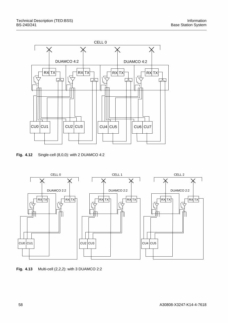
58 A30808-X3247-K14-4-7618
Technical Description (TED:BSS)BS-240/241
InformationBase Station System
Fig. 4.12 Single-cell (8,0,0): with 2 DUAMCO 4:2
Fig. 4.13 Multi-cell (2,2,2): with 3 DUAMCO 2:2
RX TX RX
DUAMCO 4:2
TX RX TX RX
DUAMCO 4:2
TX
CU4 CU5 CU6 CU7CU2 CU3CU0 CU1
CELL 0
RX TX RX
DUAMCO 2:2
TX
CU0 CU1
CELL 0
RX TX RX
DUAMCO 2:2
TX
CU2 CU3
CELL 1
RX TX RX
DUAMCO 2:2
TX
CU4 CU5
CELL 2
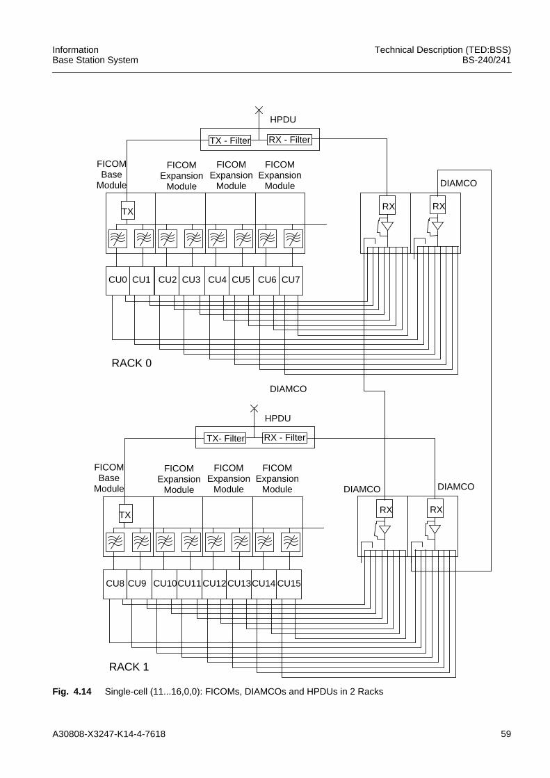
A30808-X3247-K14-4-7618 59
InformationBase Station System
Technical Description (TED:BSS)BS-240/241
Fig. 4.14 Single-cell (11...16,0,0): FICOMs, DIAMCOs and HPDUs in 2 Racks
CU4 CU5 CU6 CU7CU2 CU3
FICOMBase
Module
FICOMExpansion
Module
TX
FICOMExpansion
Module
FICOMExpansion
Module
CU0 CU1
RX RX
HPDU
DIAMCO
CU12CU13CU14 CU15CU10CU11
FICOMBase
Module
FICOMExpansion
Module
TX
FICOMExpansion
Module
FICOMExpansion
Module
CU8 CU9
RX RX
DIAMCO DIAMCO
RACK 0
RACK 1
TX - Filter RX - Filter
TX- Filter RX - Filter
DIAMCO
HPDU
60 A30808-X3247-K14-4-7618
Technical Description (TED:BSS)BS-240/241
InformationBase Station System
4.2 Receiving Paths
4.2.1 Antenna diversity techniquesBasically, there are two different diversity combining techniques:• Switched Combining• Maximum Ratio Combining
Switched Combining
Switched Combining simply selects one of the two receiver paths according to a givenquality criterion, such as maximum receiver gain.
Thus, in the case of correlated signals from receiver paths (and comparable gain),Switched Combining cannot improve receiver performance. A decision is usually madefor one full Um burst.
Maximum Ratio Combining
Maximum Ratio Combining provides bitwise combining of all available information fromboth receiver paths.
4.2.1.1 Antenna System ModulesDifferent TX, RX and TX/RX antennas are provided which are connected to thecombining modules in order to serve cells with different carrier numbers. Thesecombining modules have to provide the necessary performance by using the followingmethods:– Antenna Combining
to feed several transmitter outputs to the TX antenna– Multicoupling
for splitting the RX signal for several receiver inputs– Duplexing
both Antenna Combining and Multicoupling methods are used in order to connectthe TX- and the RX-path to one antenna
The technology of the new BTSEs knows TX Combiner (FICOM), TX and RX Combiner(DUAMCO), High Power Duplexer (HPDU) and RX Multicoupler (DIAMCO). DUAMCOand DIAMCO use a Low Noise Amplifier (LNA) in the RX path, which can be set todifferent gain to establish the various configurations of the BS-240/241. Additionally, theDUAMCO and DIAMCO have power supply and supervision functionality for a TowerMounted Amplifier.
Antenna diversity is a second receive path to improve the receive quality and the gradeof service. It is important that the diversity path is configured in the same way as thenormal path, that means either, with or without TMA. Inside the Rack, it's possible thatone RX path is realized with a DUAMCO and the other with a DIAMCO or cascadedDIAMCOs.
A solution of antenna combining and multicoupling is the configuration with twoTX-/RX-antennas and two duplex combining modules. Both antennas belong to thesame cell. One antenna is used for transmission and reception, the other for transmis-sion and diversity reception. Therefore exist two transmit paths, one normal receive pathand one diversity receive path. The combining of the two transmit paths happens 'on air'.Supervision of the two antennas will be done separately for each one.
A30808-X3247-K14-4-7618 61
InformationBase Station System
Technical Description (TED:BSS)BS-240/241
The principle of On Air Combining will also be used, if TX combining beyond the Rackborders is required. For e.g. to combine 24 carriers, belonging to the same cell, 3FICOMs will be used, each combines 8 carriers to one antenna. Combining of thesignals from the 3 antennas takes place 'On Air'.
4.2.2 Receiver SensitivityObtaining sensitivity better than the GSM requirements at the Rack entry is by usingDUAMCOs or DIAMCOs, and obtaining sensitivity better than the GSM requirements atthe antenna connector accomplished by using Tower Mounted Amplifiers (TMAs). Theconfiguration with TMA is advantageous because of highest sensitivity of the RX path.One TMA is needed for every created RX path of DUAMCO and / or DIAMCO installedand not cascaded.
Expansion of the RX path beyond the borders of the Rack or Shelter is possible bycascading of the multicoupling devices (DIAMCO or RX path of a DUAMCO). Withincreasing RF cable length, the noise figure rises and thus the RX sensitivity will bedegraded. The degradation is a little bit less than the additional cable loss.
In the configuration with antenna pre-amplifier, the true system RX sensitivity is guaran-teed at the antenna connector, including the antenna feeder cable attenuation. In theconfiguration without antenna pre-amplifier, the sensitivity is guaranteed only at theRack entry.
62 A30808-X3247-K14-4-7618
Technical Description (TED:BSS)BS-240/241
InformationBase Station System
5 Power Supply and Battery BackupThe AC/DC is used in the Service Rack/Shelter. It contains one or two Frames withAC/DC rectifier modules, one controller board and two LVD relays per Frame. Up to 6rectifier Modules can be inserted in one Frame; thus, the number of modules can beadapted to the actual need for specific loads. The Service Rack/Shelter with two AC/DCFrames is intended to be used to supply BTSEs with more than 8 carriers.
The AC/DC tasks are:• supplying all -48V consumers within the BTSE out of 230V AC 3 phase system for
the world market and 207V AC 2 phase system (240V phase to phase) for the USmarket
• supplying external equipment with -48V• charging and supervising of different battery types with different capacities and to
two battery backup systems per AC/DC Frame• supervising rectifiers, batteries and alarm messaging• switching off DC outputs (rectifiers as well as battery) in case of under and over
temperature• hot plug in/out• operation of two Frames in parallel
The AC/DC and the backup batteries work as an Uninterruptable Power Supply System(UPS).
The AC/DC system consists of:• Frame with AC distribution, DC Distribution, EMI-filter, signal distribution between
rectifiers and controller board via backplane• controller board with battery supervision, rectifier supervision, alarm interface,
EEPROM to store PID• up to 6 rectifier modules per Frame each 720W -48VDC (N+1 redundancy to achieve
3600W+720W).
• two LVD-Relays per AC/DC Frame
The Backup Battery guarantees continuous operation for a certain time in case of apower main breakdown or AC/DC failure. Four types of Backup Battery with nominalcapacities of 80Ah, 85Ah, 92Ah and 100Ah are available.
The capacity of the Backup Battery can be increased further by having additionalbatteries in separate Service Racks / Shelters.
Note: The Battery Backup Time can also be extended using the feature emergencyconfiguration.
5.1 Support of Emergency Operation for 3rd Party BBUSystemIn the BS-240/241 implementation the switch into emergency configuration (due to abattery discharge alarm) is triggered by an "ALARM STATUS" CAN bus message thathas been received from the CAN node of the AC/DC controller.
iDue to the maximum ambient temperature of +55 °C (+131 °F) the DCoutput power of one AC/DC module is limited to 720W.By decreasing the maximum ambient temperature to +50 °C (+122 °F) themaximum output power of one AC/DC module is increased to 800Wwithout any change in the module or in the Frame AC/DC.
A30808-X3247-K14-4-7618 63
InformationBase Station System
Technical Description (TED:BSS)BS-240/241
When a service environment (AC/DC + Battery Backup) is built on at BS-60/61 sites,after replacement of BS-60/61 with BS-240/241, the alarm line for the AC/DC converterand for the battery which do not have access to the CAN node must be connected to asite input which is used as a trigger for the emergency configuration.
A special setting of the attribute "associatedString" in the command "CREATEENVABTSE" for the corresponding site input allows the operator to indicate that thesupport of emergency configuration is required for the 3rd party battery backup unitsystem.
The string indicates from which source, AC/DC CAN node or site input, the trigger forthe emergency configuration is expected. In case the string pattern is set to"##ACDC_FAULT", the trigger is expected from the site input of the correspondingENVABTSE object. In all other cases the normal behavior is maintained. For simplicity,there is no check if the string "##ACDC_FAULT" is used for more than one ENVABTSEobject.
If the operator has set the "associatedString" attribute of an ENVABTSE object to"##ACDC_FAULT" for the AC/DC alarm line, the emergency configuration is deacti-vated if all trigger sources have ceased their alarm.
64 A30808-X3247-K14-4-7618
Technical Description (TED:BSS)BS-240/241
InformationBase Station System
6 AbbreviationsAC Alternate Current
AC Authentication Centre
ACLK Advanced Clock
ACOM Antenna Combiner
ACP AC Panel
ACTC Alarm Collection Terminal Connectionmodule
ACTM Alarm Collection Terminal for Master Rack
ACTP Alarm Collection Terminal for Slave Rack
AMCO Amplifier Multi Coupler
AMR Adaptive Multi Rate Codec
ASIC Application Specific Integrated Circuit
ASU Antenna Supervision Unit
BCC Base Core Controller
BISON Bit Switch for Optimized Network Architec-ture
BTS Base Transceiver Station
BTSE Base Transceiver Station Equipment
CC-Link Core Carrier Unit Link
COBA Core Basis
COSA Core Satellite
CU Carrier Unit
DC Direct Current
DIAMCO Diversity Amplifier Multi Coupler
DL Downlink
DUAMCO Duplex Amplifier Multi Coupler
ECU Edge Carrier Unit
EFR Enhanced Full-Rate
FICOM Filter Combiner
FPGA Field-Programmable Gate Array
FR Full-Rate
GPRS General Packed Radio System
GSMK Gaussian Minimum Shift Keying
HDLC High Level Data Link Control
HPDU High Power Duplexer Unit
HR Half-Rate
HSCSD High Speed Circuit Switched Data
HW Hardware
LE Link Equipment
LMT Local Maintenance Terminal
A30808-X3247-K14-4-7618 65
InformationBase Station System
Technical Description (TED:BSS)BS-240/241
LNA Low Noise Amplifier
LTG Loadable Timing Generation
LTL Local Test Loop
LVD Low Voltage Detect
MODUP Modulator and Upconverter
MUCO Multi Coupler
NTC Negative Thermal Coefficient
O&M Operation and Maintenance
OCVCXO Oven Controlled VCXO
OMT Operation and Maintenance Terminal
OVPT Overvoltage Protection and Tracer
PATRX Power Amplifier and Transceiver Unit
PCB Printed Circuit Board
PCM Pulse Code Modulation
PDU Power Distribution Unit
PID Product Identification Data
PSU Power Supply Unit
PWRDET Power Detector
PWRSTG Power Stage
RF Radio Frequency
RXA Analogue receiver board
RXFED Receiver Front End Diversity
RXFEM Receiver Front End Main
RXLO Receiver Local Oscillator
SELIC Serial Link Interface Controller (ASIC)
SIPRO Signal Processing Unit
TMA Tower Mounted Amplifier
TNF Tunable Narrowband Filter
TOP Tracking Oscillator
TRAU Transcoding and Rate Adaption Unit
TXA Analogue transmitter board
TXLO Transmitter Local Oscillator
UL Uplink
UPS Uninterruptable Power Supply System
VCXO Voltage Controlled Crystal Oscillator


