
EUROTHERMDRIVES
RS485/RS232CommunicationsInterface
Technical ManualHA466357U001 Issue 3
Copyright Eurotherm Drives Limited 2002
All rights strictly reserved. No part of this document may be stored in a retrieval system, or transmitted in any form orby any means to persons not employed by a Eurotherm Drives company without written permission from EurothermDrives Ltd.
Although every effort has been taken to ensure the accuracy of this document it may be necessary, without notice, tomake amendments or correct omissions. Eurotherm Drives cannot accept responsibility for damage, injury, or expensesresulting therefrom.
Compatible with Version 4.x Software

Cont.2
Please read this information BEFORE installing the equipment.
Intended UsersThis manual is to be made available to all persons who are required to install, configure orservice equipment described herein, or any other associated operation.
The information given is intended to highlight safety issues, and to enable the user to obtainmaximum benefit from the equipment.
Application AreaThe equipment described is intended for industrial motor speed control utilising AC induction orAC synchronous machines.
PersonnelInstallation, operation and maintenance of the equipment should be carried out by qualifiedpersonnel. A qualified person is someone who is technically competent and familiar with allsafety information and established safety practices; with the installation process, operation andmaintenance of this equipment; and with all the hazards involved.
REFER TO YOUR MAIN PRODUCT MANUAL FOR SPECIFIC SAFETYINFORMATION ABOUT THE DEVICE YOU ARE CONTROLLING
!Safety Information
WARRANTYEurotherm Drives warrants the goods against defects in design, materials and workmanship
for the period of 12 months from the date of delivery on the termsdetailed in Eurotherm Drives Standard Conditions of Sale IA058393C.
Eurotherm Drives reserves the right to change the content and product specification without notice.

Contents
Contents Page
Cont.3
RS485/RS232 COMMUNICATIONS INTERFACE 1
A System Overview........................................................................................... 1Protocols.......................................................................................................................1
• EI Bisynch ASCII/Binary...............................................................................1• MODBUS RTU............................................................................................2• Further Reading..........................................................................................2
Product Features ...........................................................................................................2Product Code................................................................................................................2
Installation ....................................................................................................... 3RS485/RS232 Communication Module (650V Frames 1, 2 & 3) .....................................3
• LED Indications ..........................................................................................4RS485 Communications Option (650V Frames C, D, E & F) ...........................................5Terminators ..................................................................................................................5System Recommendations .............................................................................................6
• PLC/SCADA Supervisor ..............................................................................6
Initial Set-up for EI Bisynch ASCII .................................................................... 7Configuring the Drive....................................................................................................7Configuring the PLC/SCADA Supervisor.......................................................................10ASCII Communications................................................................................................11
• What Information Can I Transfer?.............................................................11• How is the Information Transferred? .........................................................11• Programmer’s Information........................................................................13• EI Bisynch ASCII Message Protocol ............................................................14• EI Bisynch ASCII Parameter Mapping ........................................................15• EI Bisynch ASCII Sequence Diagrams ........................................................18• Transferring Data - ASCII Example Messages ............................................19
Character Definitions ..................................................................................................24Control Character Definitions ......................................................................................24Last Error Code (EE) ....................................................................................................25
Initial Set-up for MODBUS RTU...................................................................... 26Configuring the Drive..................................................................................................26Configuring the PLC/SCADA Supervisor.......................................................................29MODBUS RTU Communications ..................................................................................29
• How is the Information Transferred? .........................................................29• RTU Mode of Transmission .......................................................................30• Cyclic Redundancy Check.........................................................................30• Function Codes ........................................................................................34• Typical Transmission Line Activity ..............................................................42• MODBUS RTU Parameter Mapping...........................................................43
ASCII Table.................................................................................................................45


ASCII 1
RS485/RS232 Communications Interface
RS485/RS232 COMMUNICATIONS INTERFACE
A System OverviewThe RS485/RS232 Communications Interface provides a serial data port, allowing VSDs(variable speed drives) to be linked to form a network. Using a PLC/SCADA or other intelligentdevice, this network can be continuously controlled to provide supervision and monitoring foreach VSD in thesystem.
With each unit underlocal control, thecentral supervisorperforms only periodicsetpoint updating,control sequencing anddata collection.
In the system, thePLC/SCADAsupervisor acts as theMaster, and the VSD asthe Slave.
The network of VSDscan be set-up using justone unit’sMMI/Keypad, orconnection to ConfigEdLite (or other suitablePC programming tool).
ProtocolsEI Bisynch ASCII/Binary
Note: The RS485/RS232 Communications Interface supports EI Bisynch ASCII only, not Binary.
These communications protocols come under the heading of Binary SynchronousCommunications Data Link Control (BSCDLC).
This is all part of an internationally recognised ANSI standard protocol called BISYNCH(Binary Synchronous) and is known by the abbreviation x3.28.
They are widely used by manufacturers of computers, computer peripherals, andcommunications equipment.
EI BISYNCH, the specific form of communication used, corresponds with the following fullAmerican National Standard definition:
• ANSI Standard: x3.28, Revision: 1976
• Establishment and Termination Control Procedures Sub-category 2.5: Two-way Alternate, Non-switched Multi-point with Centralised Operation & Fast
Select
• Message Transfer Control Procedure Sub-category B1: Message Associated Blocking with Longitudinal Checking & Single Acknowledgement
This is known by the abbreviation ANSI - x3.28 - 2.5 - B1.
Advantages with this type of control system
1. Multi-wire analog transmission from a central programmablecontroller is replaced by a bussed digital system using serial datatransmission over 3 wires (RS232) or differential twisted-pairwires (RS485).
2. Digital transmission is fundamentally less noise-prone than analogmethods, and the accuracy of the transmitted data is unaffected bythe transmission medium. The use of intelligent devices at eitherend of the data link allows error checking to be used. Thisvirtually eliminates the effects of electrical noise on data integrity.It is therefore possible to issue setpoints to drives with muchhigher accuracy using this method.
3. The RS485 communication standard allows multiple drives to beconnected to a single link which can be driven from a computerserial port. Additional drives can be readily accommodatedthrough additional ports. The RS232 communication standardallows for a single drive to be connected to the master. Mostcomputers are equipped with RS232 serial ports which can beeasily converted to accommodate the RS485 standard. Modulesare available from Eurotherm Drives to make this conversion.
4. The chosen standard and protocol are compatible with otherEurotherm Group products. Temperature controls, processcontrols, data loggers and drives can communicate easily with acommon supervisory system.

2 ASCII
RS485/RS232 Communications Interface
MODBUS RTU The MODBUS RTU (Remote Terminal Unit) protocol is an efficient binary protocol in whicheach eight-bit byte in a message contains two four-bit hexadecimal characters. Each messagemust be transmitted in a continuous stream.
Further Reading Manual HP022047C: Eurotherm International BISYNCH Communications Handbook.
Product Features• Suitable for use with:
650/650V software version 4.x onwards
• Connection using 2-wire shielded twisted pair (RS485)
• Connection using 3-wire un-shielded cable (RS232)
• Configured using Function Block inputs
• Software-selectable Baud Rate
• Software-selectable Slave Address
• Direct tag access for all parameters
Product CodeThe Eurotherm Drives’ product is fully identified using an alphanumeric code which recordshow the product was assembled, and its various settings when despatched from the factory.
ProductProductProductProduct Product Code whenProduct Code whenProduct Code whenProduct Code whensupplied with the Drivesupplied with the Drivesupplied with the Drivesupplied with the Drive
Product Code whenProduct Code whenProduct Code whenProduct Code whensupplied separatelysupplied separatelysupplied separatelysupplied separately
650Frames 1, 2 & 3
Supplied separately 6513/006513/006513/006513/00 plug-in Communications Module
650VFrames 1, 2 & 3
Supplied separately 6513/006513/006513/006513/00 plug-in Communications Module
650VFrames C, D, E & F
(where X is theFrame size letter)
650VX/xxxx/xxx/xxxx/xx/x/RS485/x/x/x650VX/xxxx/xxx/xxxx/xx/x/RS485/x/x/x650VX/xxxx/xxx/xxxx/xx/x/RS485/x/x/x650VX/xxxx/xxx/xxxx/xx/x/RS485/x/x/x Factory-fitted Communications Option -not supplied separately
ASCII 3
RS485/RS232 Communications Interface
Installation
WARNING! Before installing, ensure that the drive and all wiring is electrically isolated and
cannot be made “live” unintentionally by other personnel.
Wait 5 minutes after disconnecting power before working on any part of thesystem or removing the covers from the Drive.
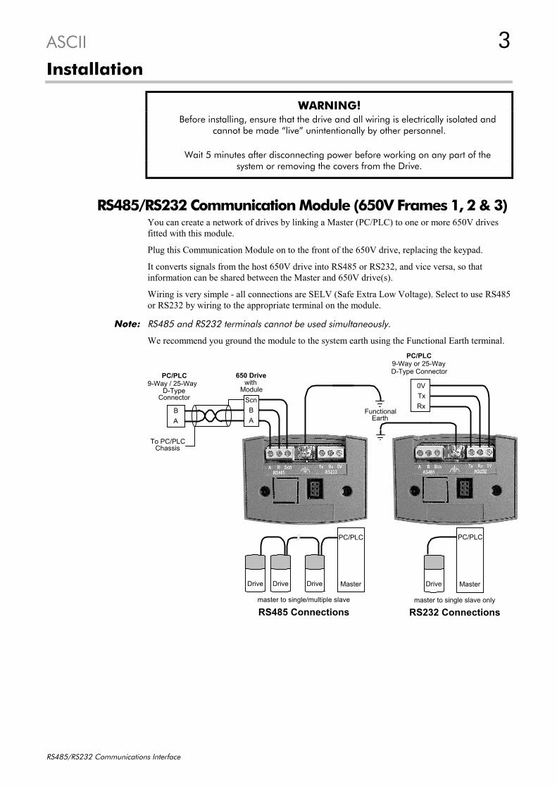
RS485/RS232 Communication Module (650V Frames 1, 2 & 3)You can create a network of drives by linking a Master (PC/PLC) to one or more 650V drivesfitted with this module.
Plug this Communication Module on to the front of the 650V drive, replacing the keypad.
It converts signals from the host 650V drive into RS485 or RS232, and vice versa, so thatinformation can be shared between the Master and 650V drive(s).
Wiring is very simple - all connections are SELV (Safe Extra Low Voltage). Select to use RS485or RS232 by wiring to the appropriate terminal on the module.
Note: RS485 and RS232 terminals cannot be used simultaneously.
We recommend you ground the module to the system earth using the Functional Earth terminal.
RS485 Connections RS232 Connectionsmaster to single/multiple slave master to single slave only
TxRx
0V
9-Way or 25-Way D-Type Connector
PC/PLC
9-Way / 25-Way D-Type
PC/PLC
AB
Scn
AB
To PC/PLCChassis
650 Drivewith
ModuleConnector
Functional Earth
Drive Master
PC/PLC
Drive Drive Drive Master
PC/PLC

4 ASCII
RS485/RS232 Communications Interface
3 Wiring SpecificationsRS485 Connections RS232 Connections
Network Type 2-Wire Shielded Twisted-Pair 3-Wire Un-Shielded Cable
Connections A=RxA/TxA, B=RxB/TxB, Shield Rx, Tx, Ground (0V)
Signal Levels To RS485 Standard To RS232 Standard
Receiver InputImpedance
¼ Unit Load 3 kΩ minimum7kΩ maximum
Maximum Cable Length 1200m (4000ft) 3 metres
Maximum Baud Rate 57.6kbaud 57.6kbaud
Maximum Number ofUnits
32 including slaves and masters 2: 1 master and 1 slaveonly
LED IndicationsThe module has three LEDs providing diagnosticinformation about the 650V host drive's ‘Health’,‘Receive’ and ‘Transmit’ activity.
HEALTH = Green, Rx = Red, Tx =Red
LED NameLED NameLED NameLED Name LED DutyLED DutyLED DutyLED Duty Drive StateDrive StateDrive StateDrive State
HEALTHHEALTHHEALTHHEALTH SHORT FLASH Re-configuration, or corrupted non-volatilememory at power-up
EQUAL FLASH Tripped
ON Healthy
LONG FLASH Braking
OFF No drive power, or serious hardware faultRx INTERMITTENT Indicates activity on the ‘receive’ line carrying
data from the MasterTx INTERMITTENT Indicates activity on the ‘transmit’ line carrying
data to the Master

ASCII 5
RS485/RS232 Communications Interface
A/18
B/17
120 Ω
RS485ON OFF
SW1
Frames 1-3 Frames C-F
RS485 Communications Option (650V Frames C, D, E & F)You can create a network of drives by linking a Master (PC/PLC) to one or more 650V drivesfitted with this additional 3-way terminal. It is factory-fitted to the right hand side of the controlboard.
Signals from the host 650V drive are converted into RS485, and vice versa, so that informationcan be shared between the Master and 650V drive(s).
Wiring is very simple - all connections are SELV (Safe Extra Low Voltage).
RS485 Connectionsmaster to single/multiple slave
9-Way / 25-Way D-Type
PC/PLC
AB
To PC/PLCChassis
AB
Scn
650V Drivewith
RS485 optionConnector
AB
Scn
650V Drivewith
RS485 option
Master
PC/PLC
DriveDriveDrive
Wiring SpecificationsRS485 Connections
Network Type 2-Wire Shielded Twisted-Pair
Connections A=RxA/TxA, B=RxB/TxB, Scn = Screen (shield)
Signal Levels To RS485 Standard
Receiver Input Impedance ¼ Unit Load
Maximum Cable Length 1200m (4000ft)
Maximum Baud Rate 57.6kbaud
Maximum Number of Units 32 including slaves and masters
TerminatorsThe last drive in a system must have a terminating resistance. All other drives in the systemshould not have a terminator.
Frames 1-3 drives require a 120Ω terminating resistorfitting to terminals 17 and 18 on the Control Board(resistor is ±1%, minimum ¼ Watt).
Frames C-F drives are fitted with an integral resistor,switched in and out by switch SW1 on the ControlBoard.
IMPORTANT: Failing to use a terminating resistance may result inunreliable operation.

6 ASCII
RS485/RS232 Communications Interface
System RecommendationsNote: It is possible to make serial communications operate without adhering to the following
recommendations, however, the recommendations will promote greater reliability.
• An RS485 two-wire system can only be used in a network in which all devices use their tri-state capability. Data flow is restricted, i.e. transmit and receive cannot be simultaneous (halfduplex). The driver in an RS485 system has tri-state capability (i.e. its output can bedisabled) which allows multiple transmitters to be connected to the same bus. RS485 thussupports “multi-drop” operation. In multi-drop systems there is always one device which is a“Master” and which sends messages to or requests data from the “Slaves”. A Slave neverinitiates a communication.
• An RS232 three-wire system always has a “Master” which sends messages to or requests datafrom the “Slave”. The Slave never initiates a communication. There is only one "Master" andone "Slave" in the system.
PLC/SCADA SupervisorIf possible, avoid using a PLC/SCADA supervisor which take its transmitter to a high impedancestate (tri-state) when idling. If it is unavoidable, then it is essential to use properly screenedcable.
RS485 Cable SpecificationUse cable which has twisted pairs andon e overall screen, as shown. Thecharacteristic impedance should be inthe range 100 to 165 Ohms.
Recommended Cable SpecificationRecommended Cable SpecificationRecommended Cable SpecificationRecommended Cable Specification
Characteristic Impedance 100-165Ω at 3-20MHz
Cable Capacitance <30pF/m
Core Diameter 0.34mm² (22 AWG)
Cable Type Twisted pair cable
Resistance <110Ω/km
Shielding Copper braid, or braid & foil
Note: Belden 9841 cable meets the above specification, but there are others.
RS232 Cable SpecificationThere are no special requirements for RS232 cabling, but we do recommend a maximum lengthof 3 metres between Master and Slave.
screeninsulation
outer sheath
conductorstwisted pair

ASCII 7
RS485/RS232 Communications Interface
Initial Set-up for EI Bisynch ASCII
Configuring the DriveNote: The RS485/RS232 Communications
Interface can only be used on drivesusing software version 4.1 or higher(indicated on power-up, i.e. "r4.1").
You must configure the drive to yoursystem.
If you are using the keypad (MMI), theparameters to edit are in the SERIALmenu, SSE01 to SSE09.
If you are using ConfigEd Lite (or othersuitable PC programming tool) thesame parameters are contained in theCOMMS PORTS and COMMSCONTROL function blocks.
ConfigEd Lite is Eurotherm Drives’Windows-based block programmingsoftware.
Note: To view all parameters available on the MMI, FULL menu detail must be selected in theDETAILED MENUS parameter ( ST99): 1 = FULL.
Parameter Descriptions : COMMS CONTROLThis block switches between Remote Terminal and Remote Comms operating modes.
The drive must be in Remote operating mode for selection to be made - REMOTE mode isenabled in the LOCAL CONTROL function block (REF MODES) or selected by the keypad.
REMOTE COMMS SEL SET\SERL SE01 Range: FALSE / TRUESelects the type of remote communications mode:0 : FALSE, and in REMOTE mode then control is from the terminals.1 : TRUE, and in REMOTE mode then control is from the communications.
REMOTE SEQ MODES Range: Enumerated - see belowSelects the type of remote sequencing mode:
Enumerated Value : Mode0 : TERMINALS/COMMS1 : TERMINALS ONLY2 : COMMS ONLY
REMOTE REF MODES Range: Enumerated - see belowSelects the type of remote reference mode:
Enumerated Value : Mode0 : TERMINALS/COMMS1 : TERMINALS ONLY2 : COMMS ONLY
COMMS TIMEOUT SET\SERL SE02 Range: 0.0 to 600.0 sSets the maximum time allowed between refreshing the COMMS COMMAND parameter. Thedrive will trip if this time is exceeded. Set the time to 0.00 seconds to disable this feature.
Comms Control– COMMS SEQ [295] – FALSE– COMMS REF [270] – FALSE– COMMS STATUS [272] – 0– COMMS COMMAND [273] – 0
FALSE – [300] REMOTE COMMS SEL –TERMINALS/COMMS – [307] REMOTE SEQ MODES –TERMINALS/COMMS – [308] REMOTE REF MODES –
0.0 s – [309] COMMS TIMEOUT –
Comms Ports0 – [102] GROUP ID (GID) –0 – [103] COMMS ADDRESS –
9600 – [1062] BAUD RATE –NONE – [1061] PARITY –
5 – [1260] REPLY DELAYAUTOMATIC – [1060] OP PORT PROTOCOL –AUTOMATIC – [1059] P3 PORT PROTOCOL –
MODBUS – [117] RS485 PROTOCOL –FALSE – [129] SWITCH OP PORT –

8 ASCII
RS485/RS232 Communications Interface
COMMS SEQ Range: FALSE / TRUEDiagnostic indicating if operating in Remote Sequencing Comms Mode.If FALSE (0), the drive may be in Local Sequencing mode or Remote Sequencing Terminalmode.
COMMS REF Range: FALSE / TRUEDiagnostic indicating if operating in Remote Reference Comms Mode.If FALSE (0), the drive may be in Local Reference mode or Remote Reference Terminal mode.
COMMS STATUS Range: 0000 to FFFFDiagnostic showing the 16-bit Status word as seen by the communications.Refer to Chapter 4: “Sequencing Logic” in the 650 or 650V Software Product Manual.
COMMS COMMAND Range: 0000 to FFFFDiagnostic showing the 16-bit Command as written by the communications.Refer to Chapter 4: “Sequencing Logic” in the 650 or 650V Software Product Manual.
Parameter Descriptions: COMMS PORTSThis function block configures the programming ports that allow connection to the keypad, or toa personal computer.
The parameters below are used to identify the drive to the controlling software for driveconfiguration and storage of parameters.
Note: The unit will always respond to GID = 0 and UID = 0, as this is the “broadcast”address used by the keypad.
GROUP ID (GID) Range: 0 to 7The Eurotherm protocol group identity address.
COMMS ADDRESS FFFF SET\SERL SE03 Range: 0 to 255The Eurotherm protocol unit identity address (UID) or the Modbus node address.Note: if set to 0, it will only respond to broadcast messages.
BAUD RATE FFFF SET\SERL SE04 Range: Enumerated - see belowSelects the Baud Rate for the MODBUS protocol.
Enumerated Value : Baud Rate0 : 12001 : 24002 : 48003 : 72004 : 96005 : 144006 : 192007 : 384008 : 57600
PARITY FFFF SET\SERL SE05 Range: Enumerated - see belowSelects the Parity for the MODBUS protocol.
Enumerated Value : Parity0 : NONE1 : ODD2 : EVEN
REPLY DELAY FFFF SET\SERL SE06 Range: 0 to 200The time in milliseconds between the drive receiving the complete request from thecommunications master (PLC/PC) and replying to this request.
ASCII 9
RS485/RS232 Communications Interface
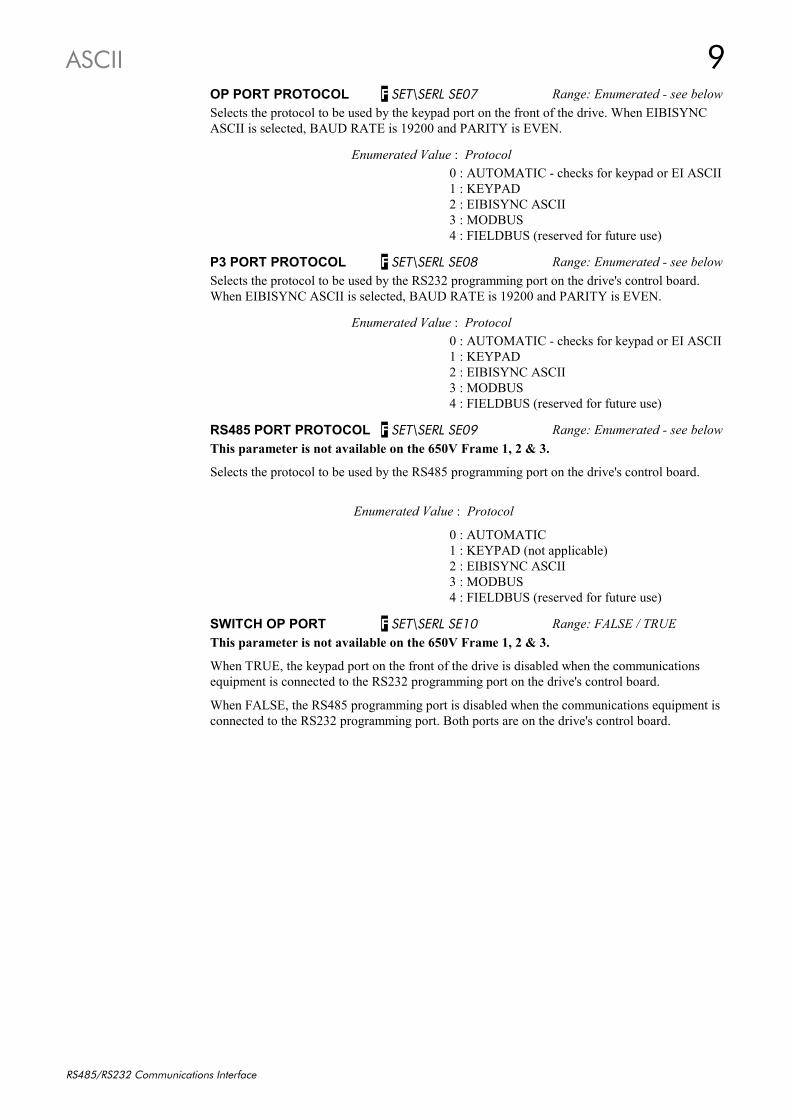
OP PORT PROTOCOL FFFF SET\SERL SE07 Range: Enumerated - see belowSelects the protocol to be used by the keypad port on the front of the drive. When EIBISYNCASCII is selected, BAUD RATE is 19200 and PARITY is EVEN.
Enumerated Value : Protocol0 : AUTOMATIC - checks for keypad or EI ASCII1 : KEYPAD2 : EIBISYNC ASCII3 : MODBUS4 : FIELDBUS (reserved for future use)
P3 PORT PROTOCOL FFFF SET\SERL SE08 Range: Enumerated - see belowSelects the protocol to be used by the RS232 programming port on the drive's control board.When EIBISYNC ASCII is selected, BAUD RATE is 19200 and PARITY is EVEN.
Enumerated Value : Protocol0 : AUTOMATIC - checks for keypad or EI ASCII1 : KEYPAD2 : EIBISYNC ASCII3 : MODBUS4 : FIELDBUS (reserved for future use)
RS485 PORT PROTOCOL FFFF SET\SERL SE09 Range: Enumerated - see belowThis parameter is not available on the 650V Frame 1, 2 & 3.
Selects the protocol to be used by the RS485 programming port on the drive's control board.
Enumerated Value : Protocol
0 : AUTOMATIC1 : KEYPAD (not applicable)2 : EIBISYNC ASCII3 : MODBUS4 : FIELDBUS (reserved for future use)
SWITCH OP PORT FFFF SET\SERL SE10 Range: FALSE / TRUEThis parameter is not available on the 650V Frame 1, 2 & 3.
When TRUE, the keypad port on the front of the drive is disabled when the communicationsequipment is connected to the RS232 programming port on the drive's control board.
When FALSE, the RS485 programming port is disabled when the communications equipment isconnected to the RS232 programming port. Both ports are on the drive's control board.

10 ASCII
RS485/RS232 Communications Interface
Configuring the PLC/SCADA SupervisorBy referring to the Parameter Specification Table in the 650 or 650V Software Product Manual,you can enter the parameter information you require.
It provides the information in the following way:
TypeThe first page of the Parameter Specification Table chapter details parameter types.The Type column indicates each parameter's type.
IDThe ID column provides the parameter mnemonic (of the tag number).
Example only

ASCII 11
RS485/RS232 Communications Interface
ASCII CommunicationsNote: The RS485/RS232 Communications Interface supports EI Bisynch ASCII only, not Binary.
What Information Can I Transfer?The data transfer sequence in the ASCII mode offers the following facilities:
i) Parameter enquiry (known as polling)
a. Single Parameter Pollb. Continuous Polling of a Parameterc. Sequential Polling (fast polling down the parameter list)
ii) Setting parameters (known as selection)
a. Single Parameter Selectionb. Continuous Selection of a Parameterc. Sequential Selection (fast selection down the parameter list)
Note: For examples of all the above refer to “Transferring Data - ASCII Example Messages”,page 19.
How is the Information Transferred?There are two types of data transfer message:
1. Reading information from the Drive
2. Writing information to the Drive
In both cases the supervisor must have an established connection with the device, which will thenrespond. The role of master and slave exchanges during the transfer.
A message consists of a sequence of characters which we identify as
• Control Characters• Instrument Address• Parameter Mnemonic• Data
Note: Refer to “EI Bisynch ASCII Message Protocol” page 14, where these four types ofcharacter are discussed in detail.
The following events take place in transmitting a successful message:
• Establish Connection• Enquiry or Set Parameter• Response• Further Transmission and/or Termination
Establish ConnectionConnection is established with a particular device by sending its two-digit address (i.e.INSTRUMENT ADDRESS as above). This comprises the GROUP ID (GID) - first digit, andthe COMMS ADDRESS (SE03) - second digit.
Note: The GROUP ID (GID) parameter is not available on the keypad and so the first digit isalways "0" when using only the keypad. Over the Comms, it can be set from 0 to 7.
Enquiry or Set ParameterThe message is either an enquiry (reading information from the Drive), or a message to set aparameter (writing information to the Drive).

12 ASCII
RS485/RS232 Communications Interface
Response to a `Set Parameter’ MessageThe Drive will respond to a Set Parameter message in one of three ways:
1. Positive Acknowledgement (ACK)
2. Negative Acknowledgement (NAK)
3. No Reply: Under certain circumstances the supervisor may not receive a reply from theDrive. This could be due to any of the following reasons:
• Group/Unit addressidentifiers notrecognised.
• An error (e.g. parity)is found in one ormore of thecharacters up to andincluding (ENQ).
• Communicationsloop failure perhapsdue to noise orwrong Baud Ratebeing selected.
• Hardware failure.
• Serial link isdisabled on theKeypad.
In these cases thesupervisor should beprogrammed to "time-out", i.e. wait for aresponse for a short time(160 msec minimum)before trying again.
Figure 1 Drive Response Sequence to an ASCII Selection Message
Further Transmission and/or Termination
Further Transmission If the supervisor still has an established connection with the device, you can repeat the previousmessage without re-establishing connection.
In both cases, writing to or reading from the device, you can use this to re-select the previousparameter or to select the next parameter in the parameter list. Refer to “Transferring Data -ASCII Example Messages”, page 19 for further explanation.
Termination (EOT) If you wish to terminate connection with a particular device and establish connection withanother, send the 'Establish Connection' sequence preceded by the (EOT) control character, (EndOf Transmission).
The (EOT) character resets all devices on the data link to be responsive to the next fourcharacters, i.e. the (GID)(GID)(UID)(UID) address.
In 2-wire operation, an (EOT) can only be sent when the supervisor has Master status.
SENDMESSAGE
PARITY CHECK
VERIFY CHECKSUM (BCC)
VERIFY THAT (C1) (C2)ARE A VALID MNEMONICAND CAN BE WRITTEN TO
OK
OK
FAIL
FAIL
FAIL
FAIL
OK
MESSAGERECEIVED
VERIFY DATA (D1)..(Dn)IS VALID AND NOT
OUT-OF-RANGE
OK
FAIL
(NAK)
NEGATIVEACKNOWLEDGEMENT
(ACK)
POSITIVEACKNOWLEDGEMENT
UPDATE THESELECTED PARAMETER
WITH THE NEW VALUECONTAINED IN THE
MESSAGE
No Reply
OK

ASCII 13
RS485/RS232 Communications Interface
Programmer’s InformationASCII (American Standard Code for Information Interchange)The RS485 Option communicates using ASCII, a binary code which represents letters, digits,and control signals (collectively called characters).
The code, originated by the American National Standards Institute (ANSI), has become a world-wide standard for information interchange. It uses a seven bit binary word to represent all theletters, digits, punctuation marks and control signals.
Handling of Numerical Data(Format 21 - Free Format Numeric)
Numerical Data is transferred as a string of characters. The drive will accept any format but willtransmit an interpreted value that always contains a decimal point, and with no trailing zeros i.e.
1.00, 1.0, 1. or 1 is interpreted as 1.-2.20 or -2.2 is interpreted as -2.2
Handling of Status Information(Format 23 - Hexadecimal)
Status Information is transmitted by first encoding the data into a hexadecimal format. Thelength of a string is then determined by the number of characters in the encoded data. Thehexadecimal data is preceded by a ‘>‘ sign to differentiate it from numerical data.
Note: Hexadecimal refers to the common practice of counting to the base of 16 in computingrather than the base of 10. The sixteen `numbers’ used being 0 to 9, A to F. Thus an 8bit byte is represented by two characters in the range 00 to FF, while a 16 bit word isrepresented by four characters in the range 0000 to FFFF.
Block Check Character (BCC)This is a checksum value generated by taking the exclusive OR (XOR) of the ASCII values of allthe characters transmitted after and excluding (STX) up to and including (ETX). For example,the shaded characters are included in the (BCC) of the following message:
(EOT) (GID) (GID) (UID) (UID) (STX) (C1) (C2) (D1) (D2) (D3) (D4) (D5 (ETX) (BCC)
Example 1: EI Bisynch Prime SetFor Beginners:You can calculate this easily by converting the ASCII values toBinary and progressively adding the Binary values together,obeying the following rules:
Referring to Example 1 on page 232, the calculation of (BCC) becomes:
As Characters HEX ASCII Binary(C1) 49 I 0 1 0 0 1 0 0 1(C2) 49 I 0 1 0 0 1 0 0 1
(D1) 3E > 0 0 1 1 1 1 1 0(D2) 32 2 0 0 1 1 0 0 1 0(D3) 36 6 0 0 1 1 0 1 1 0(D4) 35 5 0 0 1 1 0 1 0 1(D5) 30 0 0 0 1 1 0 0 0 0
(ETX) 03 (ETX) 0 0 0 0 0 0 1 1(BCC) 3C < 0 0 1 1 1 1 0 0 (TOTAL)
000
+ 110
+ 101
+ 011
+

14 ASCII
RS485/RS232 Communications Interface
EI Bisynch ASCII Message ProtocolTransmission Standard : RS485
Protocol : ANSI-X3.28-2.5-B1
Data Rates : 300, 600, 1200, 2400, 4800, 9600 or 19200 Baud
Character Format : 1 start + 7 bit ASCII data + 1 parity + 1 stop bit (10 bits)
Parity : Even
The Protocol defines the string or sequence of characters (called a Message) which must be sentbetween communicating instruments to produce specific responses. The message usuallycomprises:
• Control Characters
• Instrument Address
• Parameter Mnemonic
• Data
Control CharactersControl Characters are ASCII codes that define actions rather than information. Six ASCII codesare supported:
Keyboard HEX ASCII
^B 02 (STX) Start of Text
^C 03 (ETX) End of Text
^D 04 (EOT) End of Transmission
^E 05 (ENQ) Enquiry
^F 06 (ACK) Positive Acknowledge
^U 15 (NAK) Negative Acknowledge
Instrument AddressThe Drive has a two-digit address, the first digit being the “group” ID number (GID) in the range0 to 7, the second digit is a “unit” ID number (UID) in the range 0 to F. There are therefore 128different addresses from 00 to 7F.
The Instrument Address (01 for example) is repeated in the message (i.e. 0011) for security as itis not included in a Checksum.
Parameter MnemonicEach parameter in the Drive’s menu system is identified by a unique Tag Number. Informationis exchanged across the system by use of a two character Mnemonic that is derived from the TagNumber.
Examples are:
81 : the TRIPPED parameter from the SEQUENCING LOGIC function block
3b : the STATOR RES parameter from the MOTOR DATA function block
Note: Refer to the 650 or 650V Software Product Manual, Chapter 2 for a full listing of TagNumbers and Mnemonics.

ASCII 15
RS485/RS232 Communications Interface
EI Bisynch ASCII Parameter Mapping1. EI Bisynch ASCII Prime SetThe following prime set parameters are supported:
MnemonicMnemonicMnemonicMnemonic DescriptionDescriptionDescriptionDescription Range (HEX encoding)Range (HEX encoding)Range (HEX encoding)Range (HEX encoding) AccessAccessAccessAccessII Instrument Identity >0650, >1650 or >2650
0650 = 650 Frames 1, 2 & 31650 = 650V Frames 1, 2 & 32650 = 650V Frames C, D, E & F
Read Only
V0 Main SoftwareVersion
>0000 to >FFFF Read Only
V1 KeypadSoftware Version
>0000 to >FFFF(>0000 if not fitted)
Read Only
EE Last Error Code >0000 to >FFFF(Writing any value resets this to >00C0)
Read/Write
2. Command/StatusThe following Command/Status parameters are supported:
MnemonicMnemonicMnemonicMnemonic DescriptionDescriptionDescriptionDescription Range (Hex encoding)Range (Hex encoding)Range (Hex encoding)Range (Hex encoding) AccessAccessAccessAccess
!1 Command see below Write Only
!2 State see below Read Only
!3 Save Command see below Write Only
!4 Save State see below Read Only
!1 : CommandWrite-only: used to modify the state of the drive and to load configuration data fromnon-volatile memory.HEX ValueHEX ValueHEX ValueHEX Value DescriptionDescriptionDescriptionDescription>7777 Reset Command. Acknowledges failed restore. Loads and saves
default Product Code and default Configuration (Application 1).>0101 Restores Saved Configuration from drive’s non-volatile memory.>0110 Restores Default Configuration (Application 0)>0111 Restores Default Configuration (Application 1)>0112 Restores Default Configuration (Application 2)>0113 Restores Default Configuration (Application 3)>0114 Restores Default Configuration (Application 4)>0115 Restores Default Configuration (Application 5)>4444 Exit Configuration Mode>5555 Enter Configuration Mode
!2 : StateRead-only: used to determine the major state of the Inverter.HEX ValueHEX ValueHEX ValueHEX Value DescriptionDescriptionDescriptionDescription>0000 Initialising. (Powering up )>0001 Corrupted Product Code and Configuration>0002 Corrupted Configuration>0003 Restoring Configuration>0004 Re-Configuring Mode>0005 Normal Operation Mode

16 ASCII
RS485/RS232 Communications Interface
!3 : Save CommandWrite-only: used to save the configuration and product code in non-volatile memory.HEX ValueHEX ValueHEX ValueHEX Value DescriptionDescriptionDescriptionDescription
>0000 Reset Command. Acknowledges (clears) any previous save error.
>0001 Saves Configuration to drive’s non-volatile memory.
>0100 Saves Product Code to drive’s non-volatile memory.
!4 : Save StateRead only: used to determine the progress of a non-volatile saving operation.HEX ValueHEX ValueHEX ValueHEX Value DescriptionDescriptionDescriptionDescription
>0000 Idle
>0001 Saving
>0002 Failed
3. Tag AccessEach parameter in the drive’s menu system is identified by a unique Tag Number. Information isexchanged across the system by use of a two character Mnemonic that is derived from the TagNumber.
Note: Refer to the Parameter Specification Table in the 650 or 650V Software Product Manualfor a full list of tag mnemonics - see the ID column. Refer to the Notes column which givesaccess information about each parameter.
Parameter Mapping
650V AlgorithmThe algorithm to convert between tag number and 2 character mnemonics is:
if (TagNo < 1296)
m = INT (TagNo / 36) (INT: the integer part)n = TagNo MOD 36 (MOD: the remainder)if m > 9 then
char_1 = ‘a’ + (m - 10)else
char_1 = ‘0’ + mend_ifif n > 9 then
char_2 = ‘a’ + (n - 10)else
char_2 = ‘0’ + nelse
m = INT (TagNo - 1296) / 126)n = (TagNo - 1296) MOD 26char_1 = 'a' + nchar_2 = 'A' + m
end_if
The algorithm generates mnemonics containing only the characters ‘0’ to ‘9’ and‘a’ to ‘z’.

ASCII 17
RS485/RS232 Communications Interface
4. EncodingTypeTypeTypeType DescriptionDescriptionDescriptionDescription EncodingEncodingEncodingEncoding CommentsCommentsCommentsCommentsBOOL Boolean FALSE >00
TRUE >01Will accept >0 and >1
WORD 16-bit Bitstring >0000 to >FFFF Will accept leading zerosuppression, except >0
REAL Signed Integer -XXXXX. to XXXXX.-XXXX.X to XXXX.X-XXX.XX to XXX.XX-XX.XXX to XX.XXX-X.XXXX to X.XXXX
Leading zeroessuppressed up to digitbefore decimal point.Trailing zeroessuppressed after decimalpoint.
ENUM Enumerated Value( 0 to 99)
XX. Leading zeroessuppressed, except 0.
INT Unsigned Integer XXXXX. Leading zeroessuppressed up to digitbefore decimal point.
TAG Tag number -XXXXX. to XXXXX. Leading zeroessuppressed up to digitbefore decimal point.
Note: The “.” in theabove formats is notoptional. It must besent to conform to theEI-BISYNCH standard.

18 ASCII
RS485/RS232 Communications Interface
EI Bisynch ASCII Sequence Diagrams
ProtocolEvent
ESTABLISHCONNECTION
Sender SUPERVISOR
SupervisorStatus
MASTER
StatusSLAVE SLAVE
SLAVE
SUPERVISOR
MASTER
MASTER
TERMINATION
SUPERVISOR
MASTER
SLAVE
INITIALENTRY
Message Transfer
EOT
(ADD)
EOT
STX
(CMD)(DATA)ETX
(BCC) NOREPLY
ACK
NAK
(VALID)
(INVALID)
Device
SET PARAMETER RESPONSE
FURTHER SELECTION
RE-ENTRY
RE-ENTRY
DEVICE
SET PARAMETER
Figure 2 Selection Sequence for Writing Information to the Drive
ProtocolEvent
ESTABLISHCONNECTION
Sender SUPERVISOR
SupervisorStatus MASTER
StatusSLAVE SLAVE
SUPERVISOR
MASTER
TERMINATION
SUPERVISOR
MASTER
SLAVE
INITIALENTRY
RE-ENTRY
Message Transfer
EOT
(ADD)(CMD)ENQ
EOT
NOREPLY
EOT
STX
(CMD)(DATA)ETX
(BCC)
ACK
NAK
Device
ENQUIRY FURTHER ENQUIRYRESPONSE
(READ NEXTPARAMETER)
(READ SAME
FROM LIST)
PARAMETER)
FURTHER ENQUIRY
SUPERVISOR
MASTER
SLAVE
DEVICE
MASTER
SLAVE
RE-ENTRY
ENQUIRY
Figure 3 Poll Sequence for Reading Information from the Drive

ASCII 19
RS485/RS232 Communications Interface
Transferring Data - ASCII Example MessagesThe following examples show how data transfer takes place using the network, they will alsohelp to verify your communications if you using the RS485/RS232 Communications Interfacefor the first time. Many users will not become involved in generating low-level code, but forthose experienced in programming, the examples include ASCII, HEX and Control Characterinformation.
Note: Refer to “Control Character Definitions”, page 24 for a more detailed explanation of allcontrol characters.
Example 1: EI Bisynch Prime SetNote: Refer to the 650 or 650V Software Product Manual for a full list of Tag No's/ID's
(mnemonics).
Using this set of mnemonics, you can enquire about the drive. For instance, you could enquireabout the Instrument Identity:
ENQUIRY• For software users: Enter the known address of the Drive (say 01), II, and that it is an enquiry.
• For programmers, in ASCII:
(EOT) 0 0 1 1 I I (ENQ) • For programmers, in HEX:
04 30 30 31 31 49 49 05 • As Characters - Establish Connection | Ask Question:
(EOT) (GID) (GID) (UID) (UID) (C1) (C2) (ENQ)
Note: The (GID)(UID) address is always entered twice.Refer to ”Instrument Address”, page 14 for a more detailed explanation.
RESPONSE• For software users:
The Instrument Identity will be returned, in our case 2650 (representing a 650V drive, size Cto F - 1650 represents a 650V drive, size 1 to 3)
• For programmers, in ASCII:
(STX) I I > 2 6 5 0 (ETX) < • For programmers, in HEX:
02 49 49 3E 32 36 35 30 03 3C • As Characters - Valid Response:
(STX) (C1) (C2) (D1) (D2) (D3) (D4) (D5) (ETX) (BCC)
Note: The BCC checksum (XOR) of the data after and excluding (STX) up to and including (ETX)is “1111” and >31313131. Refer to ”Block Check Character (BCC)”, page 13 for a more detailedexplanation.
In Example 1, connection to a new device is being made, i.e. the “Establish Connection”information is transmitted. However, these examples can be transmitted without the “EstablishConnection” information if connection to the correct device is already established. This is shownby Examples 3, 5 & 6.

20 ASCII
RS485/RS232 Communications Interface
Example 2: Tag Access (Single Parameter Poll)Here we ask a question of a single parameter: what is the value of SETPOINT?
(Tag 254, SETPOINT, ID 72, Type REAL - see the Parameter Specification Table in the 650 or650V Software Product Manual for this information)
ENQUIRY• For software users: Enter the known address of the drive (say 01), 72, and that it is an enquiry.
• For programmers, in ASCII:
(EOT) 0 0 1 1 7 2 (ENQ) • For programmers, in HEX:
04 30 30 31 31 37 32 05 • As Characters - Establish Connection | Ask Question:
(EOT (GID) GID) (UID) (UID) (C1) (C2) (ENQ)
Note: The (GID)(UID) address is always entered twice.Refer to ”Instrument Address”, page 14 for a more detailed explanation.
RESPONSE• For software users:
The SETPOINT value will be returned, say 30. (representing 30.00%)
• For programmers, in ASCII:
(STX) 7 2 3 0 . (ETX) • For programmers, in HEX:
02 37 32 33 30 2E 03 2B • As Characters - Valid Response:
(STX) (C1) (C2) (D1) (D2) (D3) (ETX) (BCC)
Note: The BCC checksum (XOR) of the data after and excluding (STX) up to and including (ETX)is “`” and >2B2B2B2B. Refer to ”Block Check Character (BCC)”, page 13 for a more detailedexplanation.

ASCII 21
RS485/RS232 Communications Interface
Note: Example 3: Tag Access (Continuous Polling of a Parameter)
After receiving a valid response (from Example 2), you can cause the drive to repeat thatresponse without having to re-establish the connection. You can use this to continuously monitora parameter.
ENQUIRY• For software users:
Send (NAK).
• For programmers, in ASCII:
(NAK) • For programmers, in HEX:
15 • As Characters - Repeat Parameter:
(NAK)
RESPONSE The response will be as for Example 2, however the returned data will be an updated value, i.e.SETPOINT may now be 32. (representing 32.00%).

22 ASCII
RS485/RS232 Communications Interface
Example 4: Tag Access (Single Parameter Selection) Here we are writing a value to a single parameter: the value of PRESET INPUT 1 is 30.00%.
SET PARAMETER(Tag 348, PRESET INPUT 1, ID 9o, Type REAL - see the Parameter Specification Table in the650 or 650V Software Product Manual for this information)
For software users:Enter the known address of the drive (say 01), (STX), 90, 30. and (ETX).
• For programmers, in ASCII:
(EOT) 0 0 1 1 (STX) 9 o 3 0 . (ETX) ( • For programmers, in HEX:
04 30 30 31 31 02 39 6F 33 30 2E 03 78 • As Characters - Establish Connection | Data Transfer:
(EOT) (GID) (GID) (UID) (UID) (STX) (C1) (C2) (D1) (D2) (D3) (ETX) (BCC)
Note: The (GID)(UID) address is always entered twice.Note: Refer to ”Instrument Address”, page 14 for a more detailed explanation.
Note: The BCC checksum (XOR) of the data after and excluding (STX) up to and including (ETX)is “((((” and >78787878. Refer to ”Block Check Character (BCC)”, page 13 for a more detailedexplanation.
RESPONSE• For software users:
The response will be either (ACK), (NAK) or no reply. If (ACK), the parameter value will beupdated at the drive.
• For programmers, in ASCII:
either (ACK), (NAK) or no reply • For programmers, in HEX:
either 06, 15 or no reply • As Characters:
either (ACK), (NAK) or no reply

ASCII 23
RS485/RS232 Communications Interface
Example 5: Tag Access (Continuous Selection of a Parameter) You can repeat a valid selection (from Example 4) without having to re-establish connection tothe drive. You can use this to continuously update a parameter. Lets say the new value is 35.(representing 35.00%).
SET PARAMETER• For software users:
Send (STX), 90, 35. and (ETX).
• For programmers, in ASCII:
(STX) 9 o 3 5 . (ETX) - • For programmers, in HEX:
02 39 6F 33 35 2E 03 7D • As Characters - Data Transfer:
(STX) (C1) (C2) (D1) (D2) (D3) (ETX) (BCC)
Note: The BCC Checksum is the result of the new value you are sending to the drive.Note: Refer to ”Block Check Character (BCC)”, page 13 for a more detailed explanation.
RESPONSE• For software users:
The response will be either (ACK), (NAK) or no reply. If (ACK), the parameter value will beupdated at the drive.
• For programmers, in ASCII:
either (ACK), (NAK) or no reply • For programmers, in HEX:
either 06, 15 or no reply • As Characters:
either (ACK), (NAK) or no reply

24 ASCII
RS485/RS232 Communications Interface
Example 6: Tag Access (Sequential Selection) You can also repeat a valid selection (as Example 5) without having to re-establish theconnection to the drive to update any other specified parameter. Lets say the next parameter youwant to update is DIGITAL INPUT 1 INVERT whose new value is to be TRUE.
(Tag 30, DIGITAL INPUT 1 INVERT, ID 0u, Type BOOL - see the Parameter SpecificationTable in the 650 or 650V Software Product Manual for this information)
SET PARAMETER• For software users:
Send (STX), 0u, 1 and (ETX).
• For programmers, in ASCII:
(STX) 0 u > 0 1 (ETX) m • For programmers, in HEX:
02 30 F5 3E 30 31 03 F9 • As Characters - Data Transfer:
(STX) (C1) (C2) > (D1) (D2) (ETX) (BCC)
Note: The BCC Checksum is the result of the new information you are sending to the Drive.
RESPONSEThe response will be as for Example 5.
Character Definitions
Standard Character DefinitionsStandard Character DefinitionsStandard Character DefinitionsStandard Character Definitions
(GID) The Group address Identifier (repeated for security)
(UID) The Unit address identifier (repeated for security)
(C1) (C2) The two characters of the parameter mnemonic (from the Tag number)
(D1)..(Dn) The value of the requested parameter (string may be any length,determined by the data).
(BCC) Block Check Character: a character generated by taking the exclusive OR(XOR) of the ASCII values of all the characters transmitted after andexcluding (STX) up to and including (ETX)
Control Character Definitions
Standard Control Character DefinitionsStandard Control Character DefinitionsStandard Control Character DefinitionsStandard Control Character Definitions
(STX) Start of text
(ETX) End of text
(EOT) End of Transmission: resets all instruments on the link and causes them toexamine the next four transmitted characters to see if they correspond withtheir Group/Unit address identifiers
Also sent to terminate communication with a particular device.

ASCII 25
RS485/RS232 Communications Interface
Control Character Definitions when Reading InformationControl Character Definitions when Reading InformationControl Character Definitions when Reading InformationControl Character Definitions when Reading Information
(ENQ) Indicates the end of the message, and that it is an enquiry
(ACK) Sequential Polling: when transmitted after a valid response, this fetchesdata from the next parameter in the parameter list
(NAK) Continuous Polling: when transmitted after a valid response, this fetchesdata from the previously requested parameter
(EOT) The information received contained an error
Control Character Definitions when Writing InformationControl Character Definitions when Writing InformationControl Character Definitions when Writing InformationControl Character Definitions when Writing Information
(ACK) Positive Acknowledgement: the message was correctly received and theparameter updated
(NAK) Negative Acknowledgement: the message received by the drive containedan error and the parameter was not updated
Last Error Code (EE)The EI-BISYNCH Prime Set contains the EE mnemonic. The following values are returned if anenquiry (reading information from the drive) is performed on this Read/Write parameter.
Writing any value to this parameter will set the value to >00C0. Clearing the last error value maybe useful in seeing a repetitive error re-occurring.
ValueValueValueValue DescriptionDescriptionDescriptionDescription
>00C0 No error
>01C7 Invalid Mnemonic
>02C2 Checksum (BCC) error
>04C8 Attempt to read from a write-only parameter
>05C8 Attempt to write to a read-only parameter
>07C8 Invalid Data (Encoding error)
>08C8 Data out of range

26 MODBUS
RS485/RS232 Communications Interface
Initial Set-up for MODBUS RTUNote: Pages 10, 11 and 12 are repeated here as pages 29, 30 and 31 for your convenience.
Configuring the DriveNote: The RS485/RS232 Communications
Module can only be used on drivesusing software version 4.1 or higher(indicated on power-up, i.e. "r4.1").
You must configure the drive to yoursystem.
If you are using the keypad (MMI), theparameters to edit are in the SERIALmenu, SSE01 to SSE09.
If you are using ConfigEd Lite (orother suitable PC programming tool)the same parameters are contained inthe COMMS PORTS and COMMSCONTROL function blocks.
ConfigEd Lite is Eurotherm Drives’Windows-based block programmingsoftware.
Note: To view all parameters available on the MMI, FULL menu detail must be selected in theDETAILED MENUS parameter ( ST99): 1 = FULL.
Parameter Descriptions : COMMS CONTROLThis block switches between Remote Terminal and Remote Comms operating modes.
The drive must be in Remote operating mode for selection to be made - REMOTE mode isenabled in the LOCAL CONTROL function block (REF MODES) or selected by the keypad.
REMOTE COMMS SEL SET\SERL SE01 Range: FALSE / TRUESelects the type of remote communications mode:0 : FALSE, and in REMOTE mode then control is from the terminals.1 : TRUE, and in REMOTE mode then control is from the communications.
REMOTE SEQ MODES Range: Enumerated - see belowSelects the type of remote sequencing mode:
Enumerated Value : Mode0 : TERMINALS/COMMS1 : TERMINALS ONLY2 : COMMS ONLY
REMOTE REF MODES Range: Enumerated - see belowSelects the type of remote reference mode:
Enumerated Value : Mode0 : TERMINALS/COMMS1 : TERMINALS ONLY2 : COMMS ONLY
COMMS TIMEOUT SET\SERL SE02 Range: 0.0 to 600.0 sSets the maximum time allowed between refreshing the COMMS COMMAND parameter. Thedrive will trip if this time is exceeded. Set the time to 0.00 seconds to disable this feature.
Comms Control– COMMS SEQ [295] – FALSE– COMMS REF [270] – FALSE– COMMS STATUS [272] – 0– COMMS COMMAND [273] – 0
FALSE – [300] REMOTE COMMS SEL –TERMINALS/COMMS – [307] REMOTE SEQ MODES –TERMINALS/COMMS – [308] REMOTE REF MODES –
0.0 s – [309] COMMS TIMEOUT –
Comms Ports0 – [102] GROUP ID (GID) –0 – [103] COMMS ADDRESS –
9600 – [1062] BAUD RATE –NONE – [1061] PARITY –
AUTOMATIC – [1060] OP PORT PROTOCOL –AUTOMATIC – [1059] P3 PORT PROTOCOL –
MODBUS – [117] RS485 PROTOCOL –FALSE – [129] SWITCH OP PORT –

MODBUS 27
RS485/RS232 Communications Interface
COMMS SEQ Range: FALSE / TRUEDiagnostic indicating if operating in Remote Sequencing Comms Mode.If FALSE (0), the drive may be in Local Sequencing mode or Remote Sequencing Terminalmode.
COMMS REF Range: FALSE / TRUEDiagnostic indicating if operating in Remote Reference Comms Mode.If FALSE (0), the drive may be in Local Reference mode or Remote Reference Terminal mode.
COMMS STATUS Range: 0000 to FFFFDiagnostic showing the 16-bit Status word as seen by the communications.Refer to Chapter 4: “Sequencing Logic” in the 650 or 650V Software Product Manual.
COMMS COMMAND Range: 0000 to FFFFDiagnostic showing the 16-bit Command as written by the communications.Refer to Chapter 4: “Sequencing Logic”in the 650 or 650V Software Product Manual.
Parameter Descriptions: COMMS PORTSThis function block configures the programming ports that allow connection to the keypad, or toa personal computer.
The parameters below are used to identify the drive to the controlling software for driveconfiguration and storage of parameters.
Note: The unit will always respond to GID = 0 and UID = 0, as this is the “broadcast”address used by the keypad.
GROUP ID (GID) Range: 0 to 7The Eurotherm protocol group identity address.
COMMS ADDRESS FFFF SET\SERL SE03 Range: 0 to 255The Eurotherm protocol unit identity address or the Modbus node address.Note: if set to 0, it will only respond to broadcast messages.
BAUD RATE FFFF SET\SERL SE04 Range: Enumerated - see belowSelects the Baud Rate for the MODBUS protocol.
Enumerated Value : Baud Rate0 : 12001 : 24002 : 48003 : 72004 : 96005 : 144006 : 192007 : 384008 : 57600
PARITY FFFF SET\SERL SE05 Range: Enumerated - see belowSelects the Parity for the MODBUS protocol.
Enumerated Value : Parity0 : NONE1 : ODD2 : EVEN

28 MODBUS
RS485/RS232 Communications Interface
OP PORT PROTOCOL FFFF SET\SERL SE06 Range: Enumerated - see belowSelects the protocol to be used by the keypad port on the front of the drive. When EIBISYNCASCII is selected, BAUD RATE is 19200 and PARITY is EVEN.
Enumerated Value : Protocol0 : AUTOMATIC - checks for keypad or EI ASCII1 : KEYPAD2 : EIBISYNC ASCII3 : MODBUS4 : FIELDBUS (reserved for future use)
P3 PORT PROTOCOL FFFF SET\SERL SE07 Range: Enumerated - see belowSelects the protocol to be used by the RS232 programming port on the drive's control board.When EIBISYNC ASCII is selected, BAUD RATE is 19200 and PARITY is EVEN.
Enumerated Value : Protocol0 : AUTOMATIC - checks for keypad or EI ASCII1 : KEYPAD2 : EIBISYNC ASCII3 : MODBUS4 : FIELDBUS (reserved for future use)
RS485 PORT PROTOCOL FFFF SET\SERL SE08 Range: Enumerated - see belowThis parameter is not available on the 650V Frame 1, 2 & 3.
Selects the protocol to be used by the RS485 programming port on the drive's control board.
Enumerated Value : Protocol
0 : AUTOMATIC1 : KEYPAD (not applicable)2 : EIBISYNC ASCII3 : MODBUS4 : FIELDBUS (reserved for future use)
SWITCH OP PORT FFFF SET\SERL SE09 Range: FALSE / TRUEThis parameter is not available on the 650V Frame 1, 2 & 3.
When TRUE, the keypad port on the front of the drive is disabled when the communicationsequipment is connected to the RS232 programming port on the drive's control board.
When FALSE, the RS485 programming port is disabled when the communications equipment isconnected to the RS232 programming port. Both ports are on the drive's control board.

MODBUS 29
RS485/RS232 Communications Interface
Configuring the PLC/SCADA SupervisorBy referring to the Parameter Specification Table in the 650 or 650V Software Product Manual,you can enter the parameter information you require.
It provides the information in the following way:
TypeThe first page of the Parameter Specification Table chapter details parameter types.The Type column indicates each parameter's type.
TAGThe TAG column provides the unique identification tag number.
Example only
MODBUS RTU Communications A MODBUS RTU communication network can have only one Master, and one or more Slavedevices.
• Each Slave has a unique “device address”
• The device address “0” is a special case and is used for messages that are broadcast to allSlaves. This is restricted to parameter write operations.
• The unit supports a subset of MODBUS RTU function codes.
• The data includes parameters referenced by a “parameter address”.
• Sending a communication with a unique device address causes only the device with thataddress to respond. That device will check for errors, perform the requested task and thenreply with its own address, data and check sum.
• Sending a communication with the device address “0” is a broadcast communication thatsends information to all devices on the network. Each device performs the required action butdoes not transmit a reply.
How is the Information Transferred? A typical transaction consists of a request sent from the Master followed by a response from theSlave.
A message consists of a sequence of characters which we identify as:
• Device Address• Function Code• Data• Error Check Data• End of Transmission
Device AddressEach Slave has a unique 8-bit device address. The Gould MODBUS Protocol defines the addressrange limits as 1 to 247 (device address 0 is the broadcast message to all slaves simultaneously).

30 MODBUS
RS485/RS232 Communications Interface
Parameter AddressData bits or data words exchange information between Master and Slave devices. This dataconsists of parameters. All parameters communicated between Master and Slaves have a 16-bitparameter address.
The MODBUS parameter address range is 0001 to FFFF.
RTU Mode of TransmissionThe MODBUS RTU definition of the mode of transmission for a single character is:
A start bit, eight data bits, a parity bit, one or two stop bits
All Eurotherm Drives’ units use one stop bit.
Parity may be configured to be NONE, ODD or EVEN (if NONE, no parity bit is transmitted)
The RTU mode of transmission for a single character is represented as follows:
Start d7 d6 d5 d4 d3 d2 d1 d0 Parity Stop
Message Frame FormatA message frame format consists of a number of correctly sequenced characters, as shownbelow.
Frame Start Device Address Function Code Data CRC EOT
3 bytes 1 byte 1 byte n bytes 2 bytes 3 bytes
Frame StartThe frame start is a period of inactivity at least 3.5 times the single character transmission time.For example, at 9600 baud a character with a 1 start, 1 stop and 8 data bits will require 3.5msframe start. This period is the implied EOT of a previous transmission.
Device AddressThe device address is a single byte (8-bits), unique to each device on the network.
Function CodeFunction codes are a single byte instruction to the Slave describing the action to perform.
DataThe Data segment of a message will depend on the function code and the number of bytes willvary accordingly. Typically, the data segment will contain a parameter address and the numberof parameters to read or write.
CRCThe CRC (Cyclic Redundancy Check) is an error code and is 2 bytes (16-bits) long.
EOTThe EOT (End Of Transmission) segment is a period of inactivity 3.5 times the single charactertransmission time. The EOT segment at the end of a message indicates to the listening devicethat the next transmission will be a new message and therefore a device address character.
Cyclic Redundancy CheckThis is an error check code and is 2 bytes (16-bits) long. After constructing a message (data only- no start, stop or parity bits), the transmitting device calculates a CRC code and appends this tothe end of the message. The receiving device also calculates a CRC code from the receivedmessage. If this CRC code is not the same as the transmitted CRC there has been acommunication error. Units do not reply if they detect a CRC error in messages sent to them.

MODBUS 31
RS485/RS232 Communications Interface
The CRC code is formed by the following steps:
1. Load a 16-bit CRC register with FFFFh.
2. Exclusive OR ( ) the first 8-bit byte of the message with the high order byte of the CRCregister. Return the result to the CRC register.
3. Shift the CRC register one bit to the right.
4. If the overflow bit (or flag) is 1, exclusive OR the CRC register with A001 hex and return theresult to the CRC register.
5. Repeat steps 3 & 4 seven times (8 in total).
6. Exclusive OR the next 8-bit byte of the message with the high order byte of the CRC register.
7. Repeat step 3 through 6 until all bytes of the message have been exclusive OR’d with theCRC register and shifted 8 times.
8. The contents of the CRC register are the 2 byte CRC error code and are added to the messagewith the most significant bits first.
The flow chart below illustrates this CRC error check algorithm.
START
FFFFh CRC Register
CRC Register next byte of the message CRC Register
0 n
Shift CRC Register right 1 bit
Overflow?NO
YES
CRC Register A001h CRC Register
n + 1 n
NOn > 7?
YES
NO
YES
message
END
complete? Is

32 MODBUS
RS485/RS232 Communications Interface
Example of a CRC CalculationThis example is a request to read from the Slave unit at address 02, the fast read of the status(07).
FunctionFunctionFunctionFunction 16 Bit Register16 Bit Register16 Bit Register16 Bit Register CarryCarryCarryCarryLSBLSBLSBLSB MSBMSBMSBMSB FlagFlagFlagFlag
Load register with FFFF hex 1111 1111 1111 1111 0First byte of the message (02) 0000 0010Exclusive OR 1111 1111 1111 11011st shift right 0111 1111 1111 1110 1A001 1010 0000 0000 0001Exclusive OR (carry = 1) 1101 1111 1111 11112nd shift right 0110 1111 1111 1111 1A001 1010 0000 0000 0001Exclusive OR (carry = 1) 1100 1111 1111 11103rd shift right 0110 0111 1111 1111 04th shift right (carry = 0 ) 0011 0011 1111 1111 1A001 1010 0000 0000 0001Exclusive OR (carry = 1) 1001 0011 1111 11105th shift right 0100 1001 1111 1111 06th shift right (carry = 0 ) 0010 0100 1111 1111 1A001 1010 0000 0000 0001Exclusive OR (carry = 1) 1000 0100 1111 11107th shift right 0100 0010 0111 1111 08th shift right (carry = 0) 0010 0001 0011 1111 1A001 1010 0000 0000 0001Exclusive OR (carry = 1) 1000 0001 0011 1110Next byte of the message (07) 0000 0111Exclusive OR (shift = 8) 1000 0001 0011 10011st shift right 0100 0000 1001 1100 1A001 1010 0000 0000 0001Exclusive OR (carry = 1) 1110 0000 1001 11012nd shift right 0111 0000 0100 1110 1A001 1010 0000 0000 0001Exclusive OR (carry = 1) 1101 0000 0100 11113rd shift right 0110 1000 0010 0111 1A001 1010 0000 0000 0001Exclusive OR (carry = 1) 1100 1000 0010 01104th shift right 0110 0100 0001 0011 05th shift right (carry = 0) 0011 0010 0000 1001 1A001 1010 0000 0000 0001Exclusive OR (carry = 1) 1001 0010 0000 10006th shift right 0100 1001 0000 0100 07th shift right (carry = 0) 0010 0100 1000 0010 08th shift right (carry = 0) 0001 0010 0100 0001 0CRC error check codeCRC error check codeCRC error check codeCRC error check code 12h12h12h12h 41h41h41h41h
The final message transmitted including the CRC code is:
Device AddressDevice AddressDevice AddressDevice Address Function CodeFunction CodeFunction CodeFunction Code CRC MSBCRC MSBCRC MSBCRC MSB CRC LSBCRC LSBCRC LSBCRC LSB
02h 07h 41h 12h
0000 0010 0000 0111 0100 0001 0001 0010
↑ First bit Transmission order Last bit ↑

MODBUS 33
RS485/RS232 Communications Interface
Example of a CRC Calculation in the “C” LanguageThis routine assumes that the data types “uint16” and “uint8” exist. These are unsigned 16 bitinteger (usually an “unsigned short int” for most compiler types) and unsigned 8 bit integer(unsigned char).
“z_p” is a pointer to a Modbus message, and z_message_length is its length, excluding the CRC.
Note that the Modbus message will probably contain “NULL” characters and so normal C stringhandling techniques will not work.uint16 calculate_crc (uint8 *z_p, uint16 z_message_length)
/* CRC runs cyclic Redundancy Check Algorithm on input z_p *//* Returns value of 16 bit CRC after completion and *//* always adds 2 crc bytes to message *//* returns 0 if incoming message has correct CRC */
uint16 CRC = 0xffff; uint16 next; uint16 carry; uint16 n; uint8 crch, crcl;
while (z_message_length--) next = (uint16)*z_p;CRC ^= next;for (n = 0; n < 8; n++)
carry = CRC & 1;CRC >> = 1;if (carry)
CRC ^= 0xa001;
z_p++;
crch = CRC / 256; crcl = CRC % 256; *z_p++ = crcl; *z_p = crch; return CRC;
Example of a CRC Calculation in Basic LanguageFunction CRC (messages) as long‘‘ CRC runs Cyclic Redundancy Check Algorithm on input message$‘‘ Returns value of 16 bit CRC after completion and‘‘ always adds 2 crc bytes to message‘‘ returns 0 if incoming message has correct CRC
‘‘ Must use double word for CRC and decimal constants
crc16& = 65535 FOR c% = 1 to LEN(message$)
crc16& = crc16& XOR ASC(MID$(message$, c%, 1))FOR bit% = 1 to 8
IF crc16& MOD 2 THEN crc16& = (crc16& \ 2) XOR 40961ELSE crc16& = crc16& \ 2END IF
NEXT BIT% NEXT c% crch% = CRC16& \ 256: crcl% = CRC16& MOD 256 message$ = message$ + CHR$(crcl%) + CHR$(crch%) CRC = CRC16&END FUNCTION CRC

34 MODBUS
RS485/RS232 Communications Interface
Function CodesFunction codes are a single byte instruction to the Slave describing the action to perform.
The following communication functions are supported by Eurotherm Drives’ units:
Function CodeFunction CodeFunction CodeFunction Code FunctionFunctionFunctionFunction01 or 02 Read n bits03 or 04 Read n words05 Write 1 bit06 Write 1 word08 Loopback15 Write n bits16 Write n words
Read n BitsFunction Code: 01 or 02, (01h or 02h)
Command:
Device Address Function Code01 or 02
Address of1st bit
Number of bitsto read
CRC
1 byte 1 byte MSB LSB MSB LSB MSB LSB
The maximum number of bits that may be read is 512.
Reply:
DeviceAddress
Function Code01 or 02
Numberof bits to
read
First byteof data
.... Last byteof data
CRC
1 byte 1 byte 1 byte 1 byte .... 1 byte MSB LSB
The first data byte contains the status of the first 8 bits, with the least significant bit being thefirst bit. The second data byte contains the status of the next 8 bits, etc. Unused bits are set tozero.
ExampleFrom the unit at device address 02, read 14 parameters, beginning at Tag 640:
Command:
Device Address Function Code01 or 02
Address of1st bit
Number of bitsto read
CRC
02 01 02 7F 00 0E 8D 97
Reply:
DeviceAddress
Function Code01 or 02
Number ofbytes read
First byteof data
Last byteof data
CRC
02 01 02 27 03 A6 0D
An expansion of the data bytes illustrates the relationship between data and the parameteraddresses.
Data byte 1st byte (27h) 2nd byte (03h)
Param. address 647 646 645 644 643 642 641 640 653 652 651 650 649 648
Bit values 0 0 1 0 0 1 1 1 0 0 0 0 0 0 1 1

MODBUS 35
RS485/RS232 Communications Interface
Read n WordsFunction Code: 03 or 04, (03h or 04h)
Command:
Device Address Function Code03 or 04
Address of1st word
Number ofwords to read
CRC
1 byte 1 byte MSB LSB MSB LSB MSB LSB
The maximum number of words that may be read is 32.
Reply:
DeviceAddress
Function Code03 or 04
Number ofbytes read
Value of 1stword
.... Value oflast word
CRC
1 byte 1 byte 1 byte MSB LSB .... MSB LSB MSB LSB
ExampleFor a 650V drive at device address 02, read 2 parameters beginning at Tag 254 (Speed Setpointand Speed Demand). SPEED SETPOINT is 100.00% and SPEED DEMAND is 50.00%.
Command:
Device Address Function Code03 or 04
Address of1st word
Number ofwords to read
CRC
02 03 00 FD 00 02 55 C8
Reply:
DeviceAddress
Function Code03 or 04
Number ofbytes read
Value of 1stword
Value of lastword
CRC
02 03 04 27 10 13 88 CF 14

36 MODBUS
RS485/RS232 Communications Interface
Write 1 BitFunction Code: 05, (05h)
Command:
Device Address Function Code05
Address of bit Value of bit CRC
1 byte 1 byte MSB LSB MSB LSB MSB LSB
The LSB of “Value of bit” is always set to 00. The MSB is used to write the value of theaddresses bit. To set a bit value of 1, either transmit 01h or FFh. To set a bit value of 0 transmit00h.
A device address 00 will broadcast the data to all devices on the network.
Reply:
(There will be no reply to a command broadcast to the device address 00.)
Device Address Function Code05
Address of bit Value of bit CRC
1 byte 1 byte MSB LSB MSB LSB MSB LSB
The reply to function 05 is the same as the command.
ExampleWrite to the unit at device address 02 setting the parameter with Tag 3 to be TRUE..
Command:
Device Address Function Code05
Address of bit Value of bit CRC
02 05 00 02 01 00 6D A9
Reply:
Device Address Function Code05
Address of bit Value of bit CRC
02 05 00 02 01 00 6D A9

MODBUS 37
RS485/RS232 Communications Interface
Write 1 WordFunction Code: 06, (06h)
Command:
Device Address Function Code06
Address of word Value of word CRC
1 byte 1 byte MSB LSB MSB LSB MSB LSB
A device address 00 will broadcast the data to all devices on the network.
Reply:
(There will be no reply to a command broadcast to the device address 00.)
Device Address Function Code06
Address of word Value of word CRC
1 byte 1 byte MSB LSB MSB LSB MSB LSB
The reply to function 06 is the same as the command.
ExampleFor a 650V drive at device address 02, write 20.0 to ACCEL TIME (Tag 258).
Command:
Device Address Function Code06
Address of word Value of word CRC
02 06 01 01 00 C8 D8 53
Reply:
Device Address Function Code06
Address of word Value of word CRC
02 06 01 01 00 C8 D8 53

38 MODBUS
RS485/RS232 Communications Interface
Diagnostic LoopbackFunction Code: 08, (08h)
This function provides a means of testing the communications link by means of a “loopback”operation. The data sent to the unit is returned unchanged. Only diagnostic code 0 from theGould Modicon Specification is supported.
Command:
Device Address Function Code08
Diagnostic Code0000
Loopback Data CRC
1 byte 1 byte MSB LSB MSB LSB MSB LSB
Reply:
The reply to function 08 is the same as the command.
ExamplePerform a loopback from the unit at address 02 using a data value of 1234h.
Command:
Device Address Function Code08
Diagnostic Code0000
Loopback Data CRC
02 08 00 00 12 34 ED 4F
Reply:
Device Address Function Code08
Diagnostic Code0000
Loopback Data CRC
02 08 00 00 12 34 ED 4F

MODBUS 39
RS485/RS232 Communications Interface
Write n BitsFunction Code: 15, (0Fh)
Command:
DeviceAddress
Function Code0F
Address of1st word
Number ofbits to write
Number ofdata bytes
(n)
Data CRC
1 byte 1 byte MSB LSB MSB LSB 1 byte n bytes MSB LSB
The maximum number of bits that may can be transmitted is 512.
A device address 00 will broadcast the data to all devices on the network.
Reply:(There will be no reply to a command broadcast to the device address 00).
Device Address Function Code0F
Address of1st word
Number of bitswritten
CRC
1 byte 1 byte MSB LSB MSB LSB MSB LSB
ExampleWrite to the Slave unit, at device address 02, 14 parameters beginning at Tag 640 the values 1, 1,1, 0, 0, 1, 0, 0, 1, 1, 0, 0, 0, 0.
Command:
DeviceAddress
Function Code0F
Address of1st word
Number ofbits to write
Number ofdata bytes
(n)
Data CRC
02 0F 02 7F 00 0E 02 seebelow
83 06
Data byte 1st byte (27h)
Param. address 647 646 645 644 643 642 641 640
Bit values 0 0 1 0 0 1 1 1
Data byte 2nd byte (03h)
Param. address 653 652 651 650 649 648
Bit values 0 0 0 0 0 0 1 1
Reply:
Device Address Function Code0F
Address of1st word
Number of bitswritten
CRC
02 0F 02 7F 00 0E E4 5C

40 MODBUS
RS485/RS232 Communications Interface
Write n WordsFunction Code: 16, (10h)
Command:
DeviceAddress
Function Code10
Address of1st word
Number ofwords to
write
Number ofdata bytes
(n)
Data CRC
1 byte 1 byte MSB LSB MSB LSB 1 byte n bytes MSB LSB
The maximum number of words that may can be transmitted is 32.
The first 2 bytes are data with the required value of the first parameter, MSB first. Followingpairs are data for the consecutive parameter addresses.
A device address 00 will broadcast the data to all devices on the network.
Reply:(There will be no reply to a command broadcast to the device address 00).
Device Address Function Code10
Address of1st word
Number ofwords written
CRC
1 byte 1 byte MSB LSB MSB LSB MSB LSB
Example650V drive: write to the Slave unit at device address 02
Tag 258 ACCEL TIME = 20.0Tag 259 DECEL TIME = 15.0
Command:
DeviceAddress
Function Code10
Address of1st word
Number ofwords to
write
Number ofdata bytes
(n)
Data CRC
02 10 01 01 00 02 04 seebelow
31 27
Data (200) for Tag 258 Data (150) for Tag 259
00 C8 00 96
Reply:
Device Address Function Code10
Address of1st word
Number ofwords written
CRC
02 10 01 01 00 02 11 C7

MODBUS 41
RS485/RS232 Communications Interface
Error ResponseThe MODBUS protocol defines the response to a number of error conditions. A Slave device isable to detect a corrupted command or one that contains an incorrect instruction, and willrespond with an error code.
With some errors, the Slave devices on the network are unable to make a response. After a waitperiod, the Master will interpret the failure to reply as a communications error. The Mastershould then re-transmit the command.
A Slave device that has detected a corrupted command, or a command that contains in incorrectinstruction, will respond with an error message. The error message has the following syntax:
Device Address Function Code Error Response Code CRC
1 byte 1 byte 1 byte MSB LSB
The Function Code byte contains the transmitted function code but with the most significant bitset to 1. (This is the result of adding 128 to the function code.)
The error response code indicates the type of error detected. The following error response codesare supported by Eurotherm Drives’ units:
Code Error Description
01 Illegal Function The requested function is not supported by the slave.
02 Illegal Data Address The address referenced in the data field is not anallowable address for the Slave
03 Illegal Data Value The value referenced in the data field is notallowable in the addressed Slave location
06 Host Busy The slave cannot precess the request at this time. Tryagain later.
07 NAK Rejected for an unspecified reason.
Wait PeriodThere are several errors for which the Slave devices on the network are unable to make aresponse:
• If the Master attempts to use an invalid address then no Slave device will receive the message
• For a message corrupted by interference, the transmitted CRC will not be the same as theinternally calculated CRC. The Slave will reject the command and will not reply to theMaster.
After a wait period, the Master will re-transmit the command.
A wait period is also required after a broadcast communication to device address 0.
IMPORTANT: Failure to observe the wait period after a broadcast will negate the broadcast message.


