Statics:Hibbeler 1
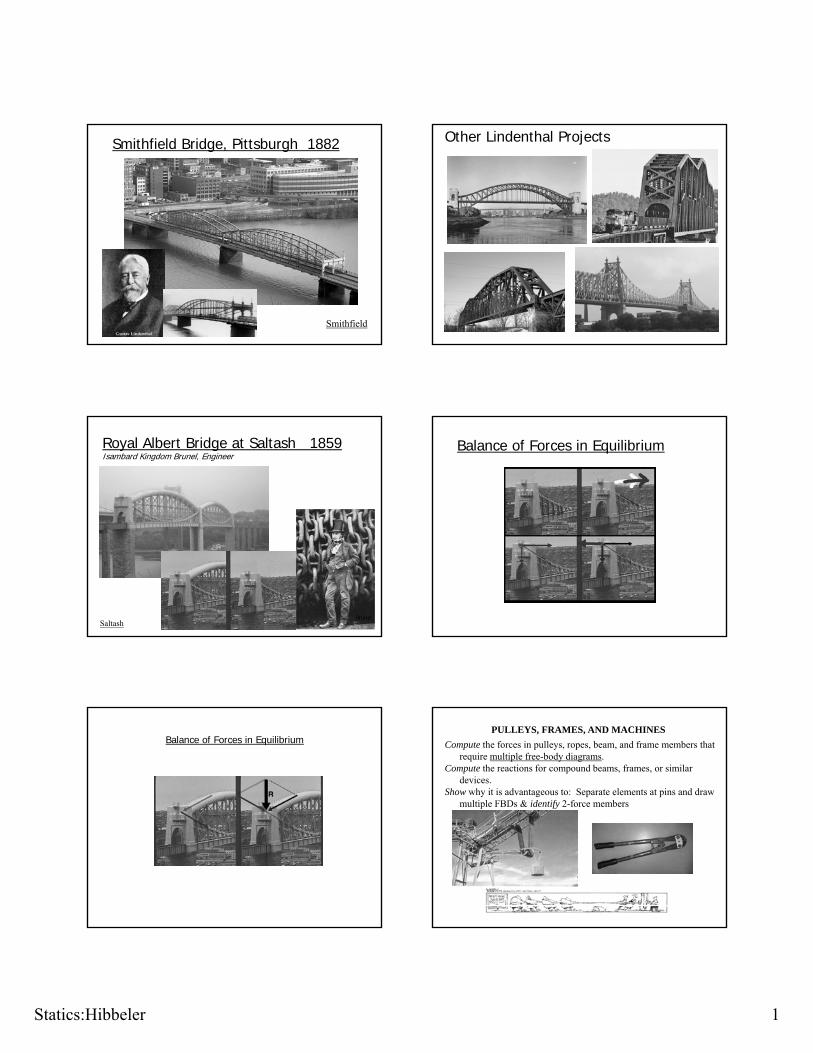
Smithfield Bridge, Pittsburgh 1882
Smithfield
Other Lindenthal Projects
Royal Albert Bridge at Saltash 1859 Isambard Kingdom Brunel, Engineer
SaltashBrunel
Balance of Forces in Equilibrium
Balance of Forces in EquilibriumPULLEYS, FRAMES, AND MACHINES
Compute the forces in pulleys, ropes, beam, and frame members that require multiple free-body diagrams.
Compute the reactions for compound beams, frames, or similar devices.
Show why it is advantageous to: Separate elements at pins and draw multiple FBDs & identify 2-force members
Statics:Hibbeler 2
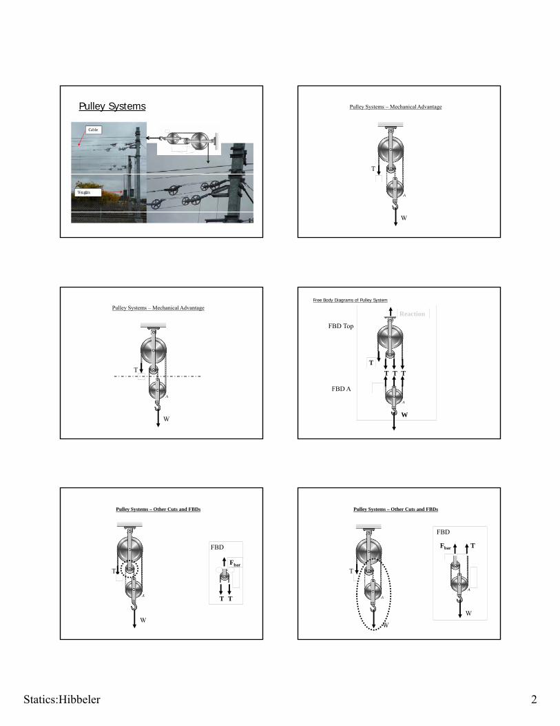
Pulley Systems Pulley Systems – Mechanical Advantage
W
T
Pulley Systems – Mechanical Advantage
W
T
Free Body Diagrams of Pulley System
FBD Top
T
Reaction
T
T
FBD A
W
T T
Pulley Systems – Other Cuts and FBDs
Fb
FBD
W
TFbar
T T
Pulley Systems – Other Cuts and FBDs
Fbar T
FBD
W
T
W

Statics:Hibbeler 3
Pulleys – Method of Joints Approach Pulleys – Method of Joints Approach
Pulleys – Method of Joints ApproachAy
P
Cy
RR
R
10 lb
FBD 2
P P R
P
10 lb 10 lb
100 lbFBD 1
FBD 3
Pulleys – Method of Sections Approach
Pulleys – Method of Sections Approach
RP
R
10 lb
100 lb
10 lb
10 lb

Statics:Hibbeler 4
QUICK PROBLEM SOLVING
Given: A frame and loads as shown.
Find: The reactions that the pins exert on the frame at A, B, and C.
Plan:
a) Draw a FBD of members AB and BC.
b) Apply the equations of equilibrium to each FBD to solve for the six unknowns.
QUICK PROBLEM SOLVING (continued)
FBDs of members AB and BC:
BY
BB
X
0.4m
500NCA X
A
B
BY
BX
1000N
45º
+ MA = BX (0.4) + BY (0.4) – 1000 (0.2) = 0
+ MC = -BX (0.4) + BY (0.6) + 500 (0.4) = 0
BY = 0 and BX = 500 N
Summing moments about A and C on each member, we get:
0.2m 0.4m
CY
AY
0.2m 0.2m
FBDs of members AB and BC:
BY
BB X
0.4m
500NC
0.2m 0.4m
C
A XA
B
BY
BX
1000N
45º
0.2m 0.2m
QUICK PROBLEM SOLVING (continued)
+ FX = AX – 500 = 0 ; AX = 500 N
+ FY = AY – 1000 = 0 ; AY = 1,000 N
For FBD of BC:
+ FX = 500 – CX = 0 ; CX = 500 N
+ FY = CY – 500 = 0 ; CY = 500 N
For FBD AB: CY
AY
WORKING EXAMPLE
Given: The wall crane supports an external load of 700 lb.
Find: The force in the cable at the winch motor W and the horizontal and vertical components of the pin reactions at A, B, C, and D.
Plan:
a) Draw FBDs of the frame’s members and pulleys.
b) Apply the equations of equilibrium and solve for the unknowns.
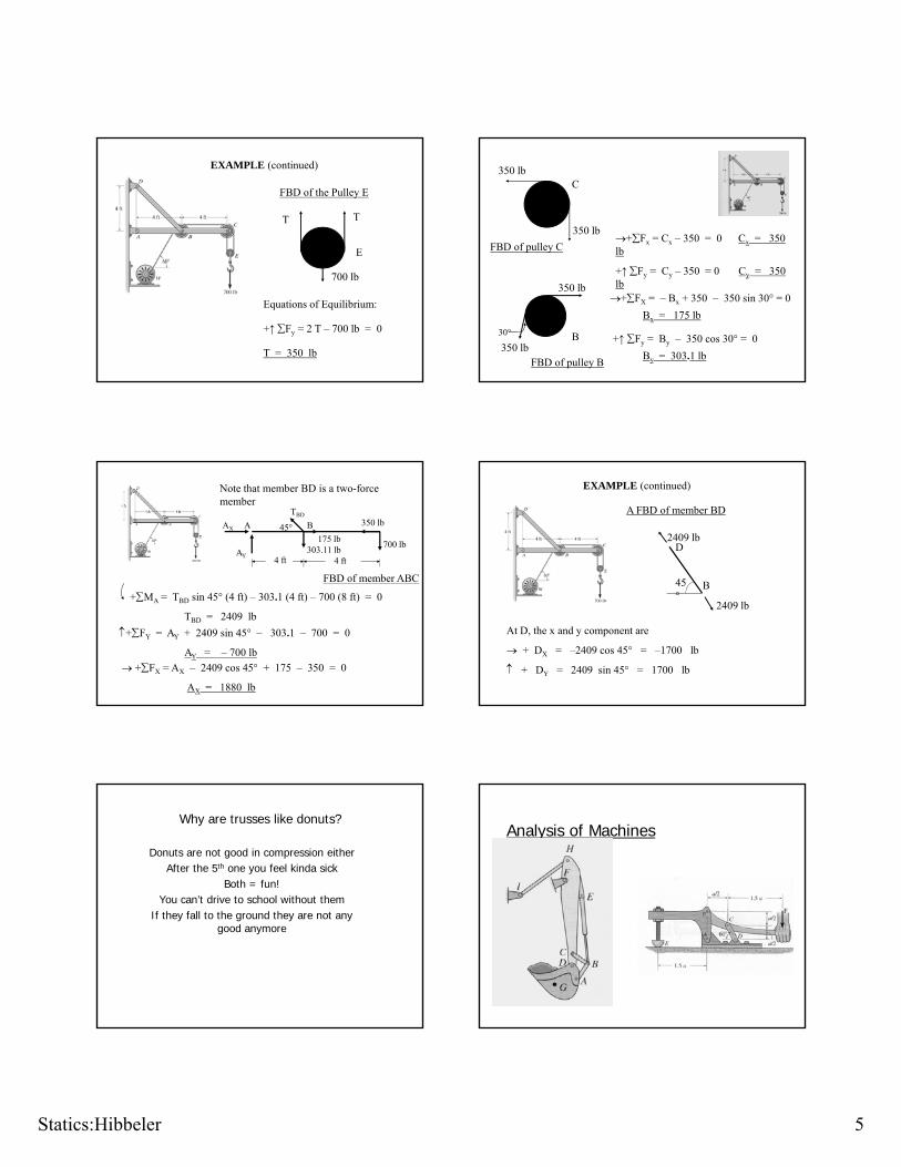
Statics:Hibbeler 5
FBD of the Pulley E
T T
E
EXAMPLE (continued)
+↑ Fy = 2 T – 700 lb = 0
T = 350 lb
700 lb
Equations of Equilibrium:
+Fx = Cx – 350 = 0 Cx = 350 lbFBD of pulley C
C
350 lb
CY
CX
350 lb
+↑ Fy = Cy – 350 = 0 Cy = 350 lb +FX = – Bx + 350 – 350 sin 30° = 0
Bx = 175 lb
+↑ Fy = By – 350 cos 30° = 0
By = 303.1 lbFBD of pulley B
BY
BX30°
350 lb
350 lb
B
Note that member BD is a two-force member
FBD of member ABC
AX
AY
A 45°
TBD
B
175 lb303.11 lb
700 lb
350 lb
4 ft 4 ft
+MA = TBD sin 45° (4 ft) – 303.1 (4 ft) – 700 (8 ft) = 0
TBD = 2409 lb
+FY = AY + 2409 sin 45° – 303.1 – 700 = 0
AY = – 700 lb
+FX = AX – 2409 cos 45° + 175 – 350 = 0
AX = 1880 lb
EXAMPLE (continued)
A FBD of member BD
45
2409 lb
B
D
At D, the x and y component are
+ DX = –2409 cos 45° = –1700 lb
+ DY = 2409 sin 45° = 1700 lb
45°
B
2409 lb
Why are trusses like donuts?
Donuts are not good in compression eitherAfter the 5th one you feel kinda sick
Both = fun!You can’t drive to school without them
If they fall to the ground they are not any good anymore
Analysis of Machines
Statics:Hibbeler 6
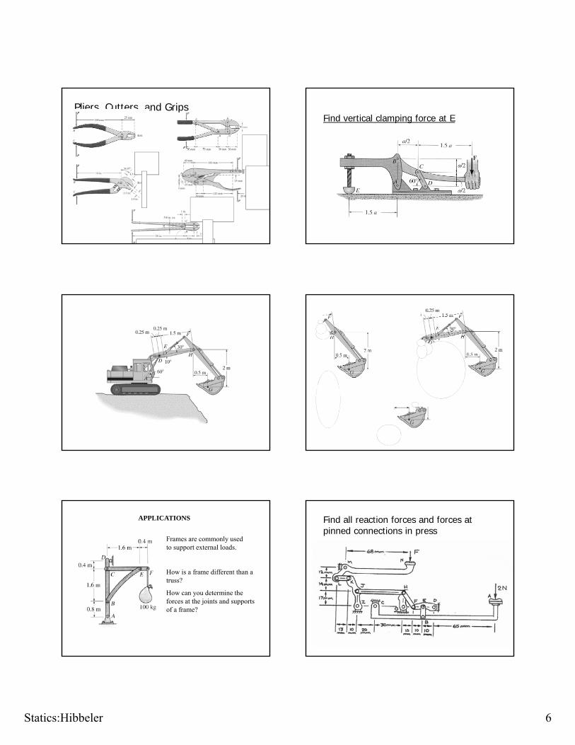
Pliers, Cutters, and GripsFind vertical clamping force at E
APPLICATIONS
Frames are commonly used to support external loads.
How is a frame different than a t ?truss?
How can you determine the forces at the joints and supports of a frame?
Find all reaction forces and forces at pinned connections in press
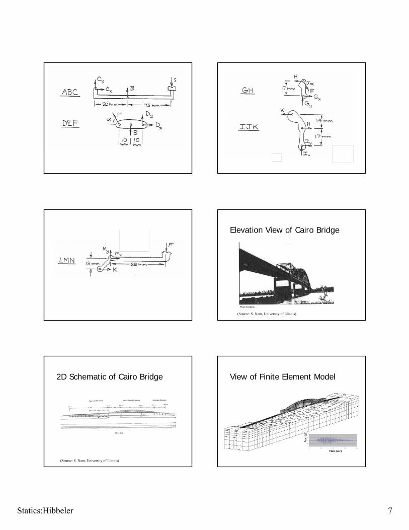
Statics:Hibbeler 7
Elevation View of Cairo Bridge
(Source: S. Nam, University of Illinois)
2D Schematic of Cairo Bridge
(Source: S. Nam, University of Illinois)
View of Finite Element Model
-1
-0.5
0
0.5
1
0 10 20 30 40
Time (sec)
Acc
. (g)
Statics:Hibbeler 8
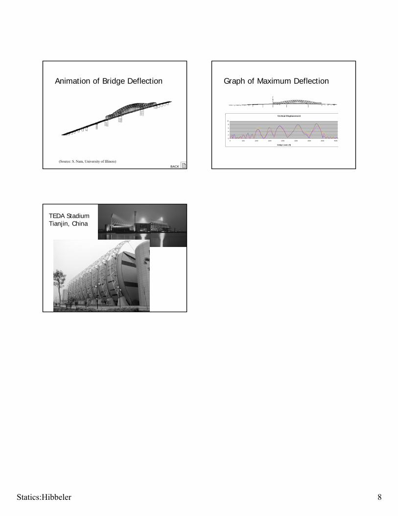
Animation of Bridge Deflection
(Source: S. Nam, University of Illinois)
BACK
Graph of Maximum Deflection
Vertical Displacement
0
2
4
6
8
10
0 500 1000 1500 2000 2500 3000 3500 4000
bridge cood. (ft)
TEDA Stadium Tianjin, China


