Download - Rowland Hall Hvac Retrofit
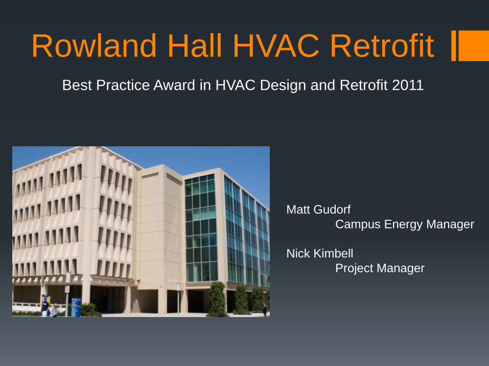
Rowland Hall HVAC RetrofitBest Practice Award in HVAC Design and Retrofit 2011
Matt Gudorf
Campus Energy Manager
Nick Kimbell
Project Manager
Overview
Building Description
Project Scope of Work
Lab Air Control Valve Installation
New Method for Occupancy Control of Office and
Support Space
Successfully completing a UC Investor Owned
Utility partnership project
Economic and Environmental Analysis
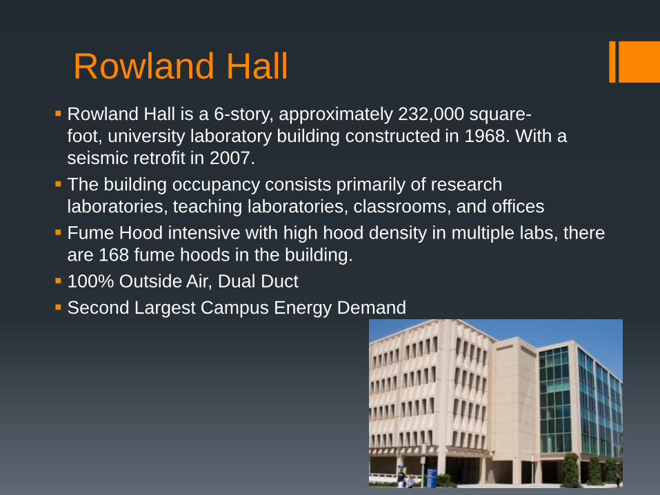
Rowland Hall Rowland Hall is a 6-story, approximately 232,000 square-
foot, university laboratory building constructed in 1968. With a
seismic retrofit in 2007.
The building occupancy consists primarily of research
laboratories, teaching laboratories, classrooms, and offices
Fume Hood intensive with high hood density in multiple labs, there
are 168 fume hoods in the building.
100% Outside Air, Dual Duct
Second Largest Campus Energy Demand
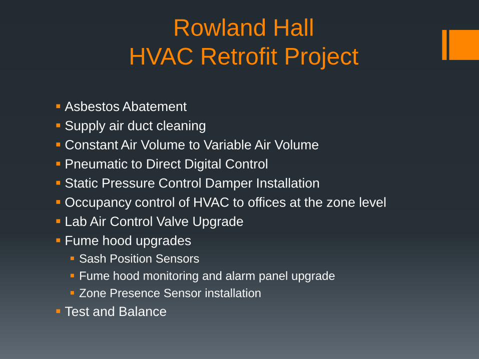
Rowland Hall
HVAC Retrofit Project
Asbestos Abatement
Supply air duct cleaning
Constant Air Volume to Variable Air Volume
Pneumatic to Direct Digital Control
Static Pressure Control Damper Installation
Occupancy control of HVAC to offices at the zone level
Lab Air Control Valve Upgrade
Fume hood upgrades
Sash Position Sensors
Fume hood monitoring and alarm panel upgrade
Zone Presence Sensor installation
Test and Balance
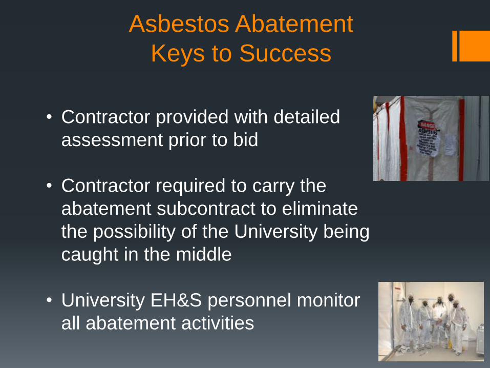
Asbestos Abatement
Keys to Success
• Contractor provided with detailed
assessment prior to bid
• Contractor required to carry the
abatement subcontract to eliminate
the possibility of the University being
caught in the middle
• University EH&S personnel monitor
all abatement activities
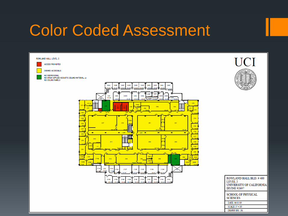
Color Coded Assessment
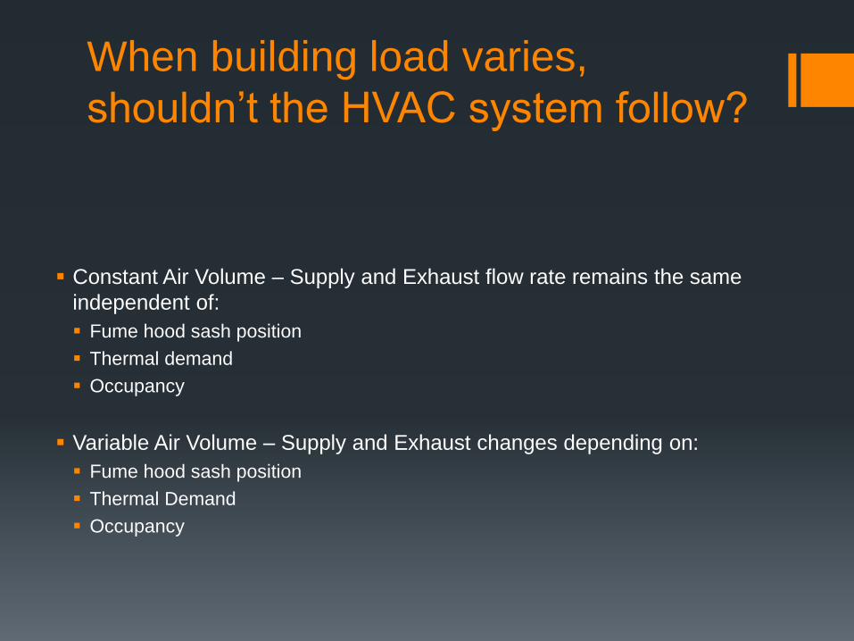
When building load varies,
shouldn’t the HVAC system follow?
Constant Air Volume – Supply and Exhaust flow rate remains the same
independent of:
Fume hood sash position
Thermal demand
Occupancy
Variable Air Volume – Supply and Exhaust changes depending on:
Fume hood sash position
Thermal Demand
Occupancy
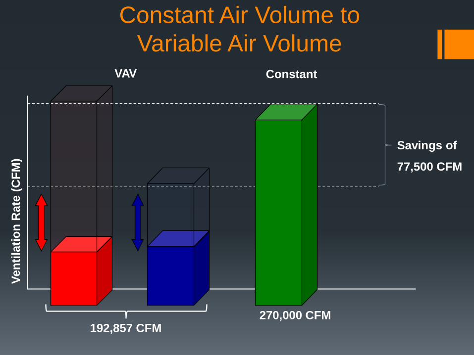
Constant Air Volume to
Variable Air VolumeConstant
Ve
nti
lati
on
Rate
(C
FM
)
VAV
270,000 CFM192,857 CFM
Savings of
77,500 CFM
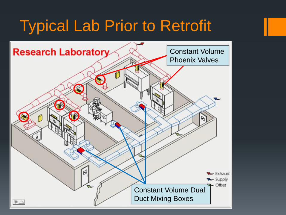
Typical Lab Prior to Retrofit
Constant Volume
Phoenix Valves
Constant Volume Dual
Duct Mixing Boxes
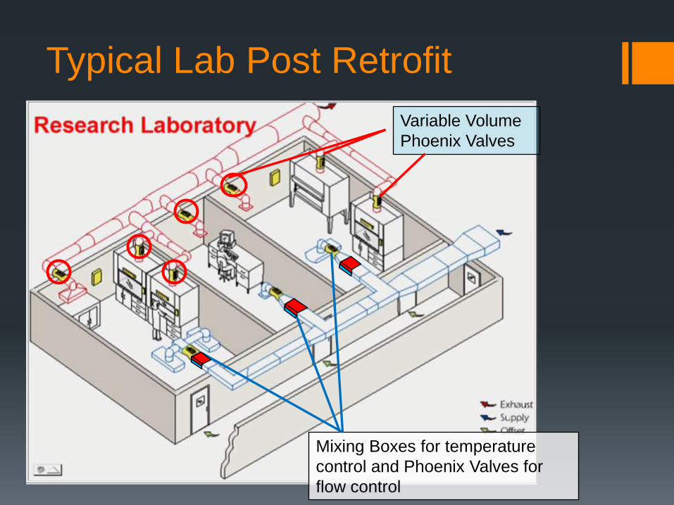
Typical Lab Post Retrofit
Variable Volume
Phoenix Valves
Mixing Boxes for temperature
control and Phoenix Valves for
flow control
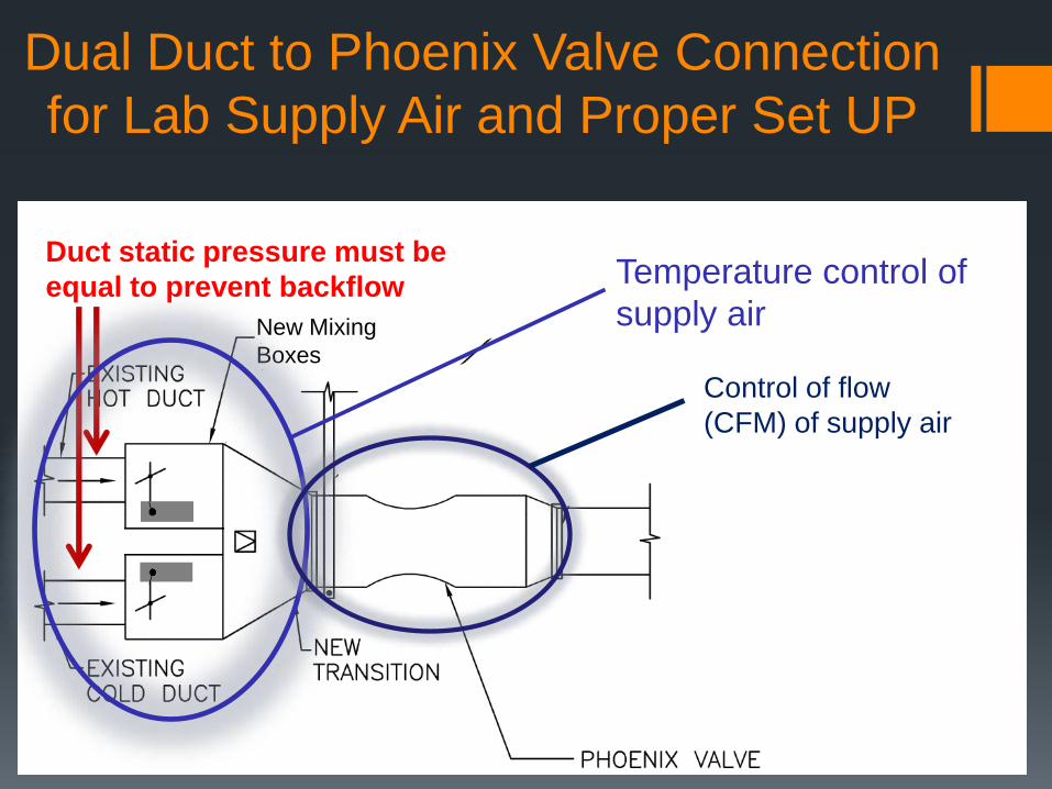
New Mixing
Boxes
Dual Duct to Phoenix Valve Connection
for Lab Supply Air and Proper Set UP
Duct static pressure must be
equal to prevent backflow Temperature control of
supply air
Control of flow
(CFM) of supply air
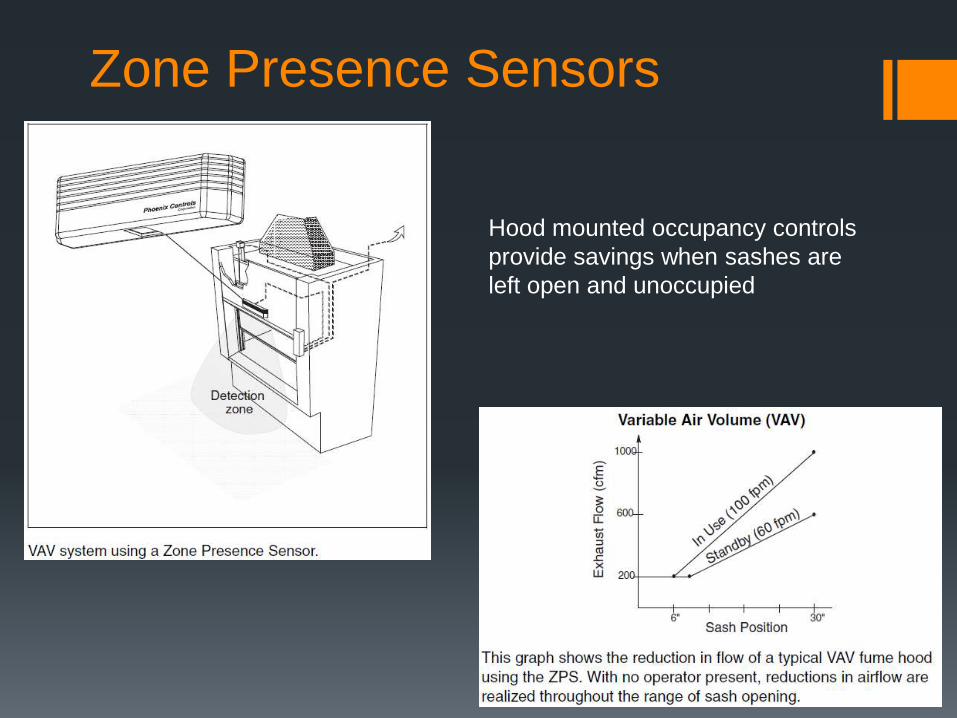
Zone Presence Sensors
Hood mounted occupancy controls
provide savings when sashes are
left open and unoccupied
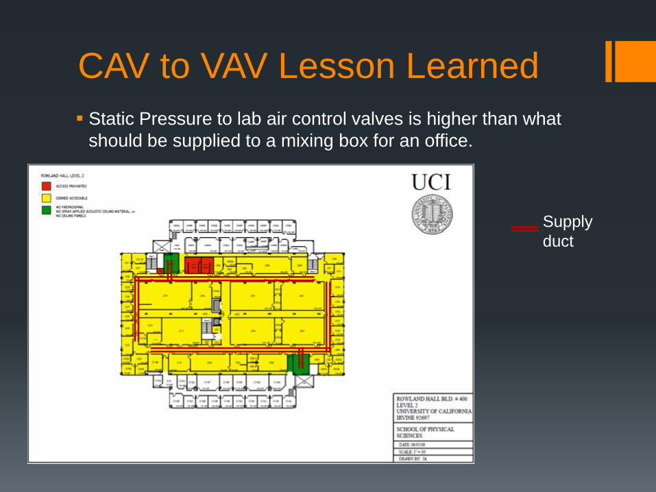
CAV to VAV Lesson Learned
Static Pressure to lab air control valves is higher than what
should be supplied to a mixing box for an office.
Supply
duct
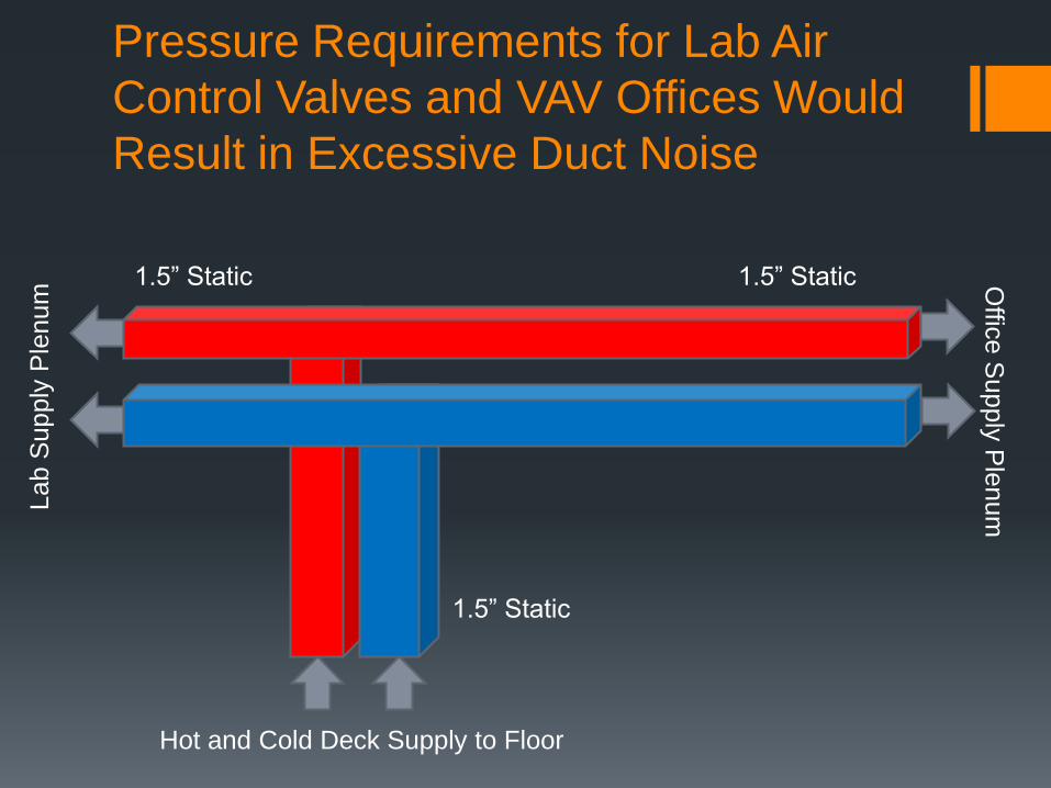
Hot and Cold Deck Supply to Floor
Lab S
upply
Ple
num
Offic
e S
upply
Ple
num
1.5” Static 1.5” Static
1.5” Static
Pressure Requirements for Lab Air
Control Valves and VAV Offices Would
Result in Excessive Duct Noise
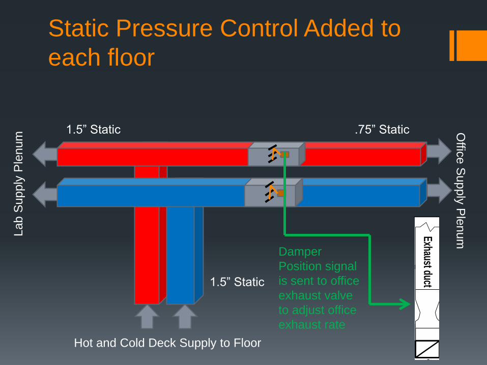
Hot and Cold Deck Supply to Floor
Lab S
upply
Ple
num
Offic
e S
upply
Ple
num
1.5” Static .75” Static
1.5” Static Tracking
Exhaust Valve
Supply
Valve
Directional A
irflow
T
Position Feedback
Actuator C
omm
andsSingle Traccel™
Room
Controller
controls two valves
Exhaust duct Supply duct
Damper
Position signal
is sent to office
exhaust valve
to adjust office
exhaust rate
Static Pressure Control Added to
each floor
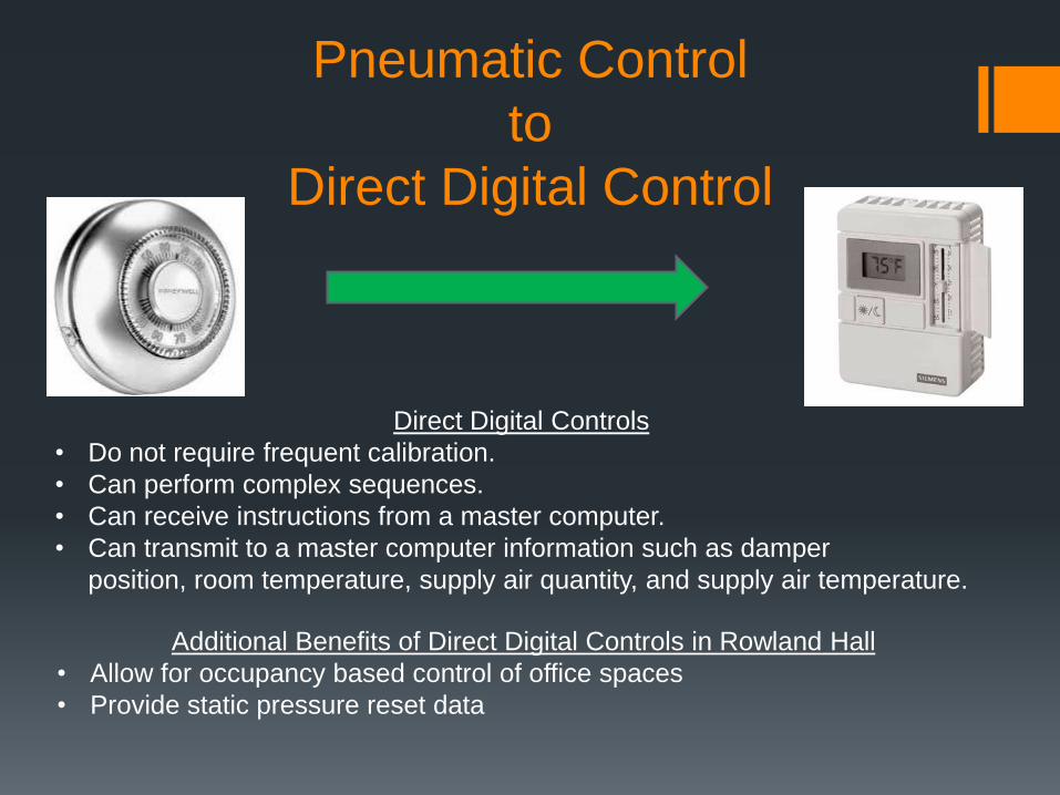
Pneumatic Control
to
Direct Digital Control
Direct Digital Controls
• Do not require frequent calibration.
• Can perform complex sequences.
• Can receive instructions from a master computer.
• Can transmit to a master computer information such as damper
position, room temperature, supply air quantity, and supply air temperature.
Additional Benefits of Direct Digital Controls in Rowland Hall
• Allow for occupancy based control of office spaces
• Provide static pressure reset data
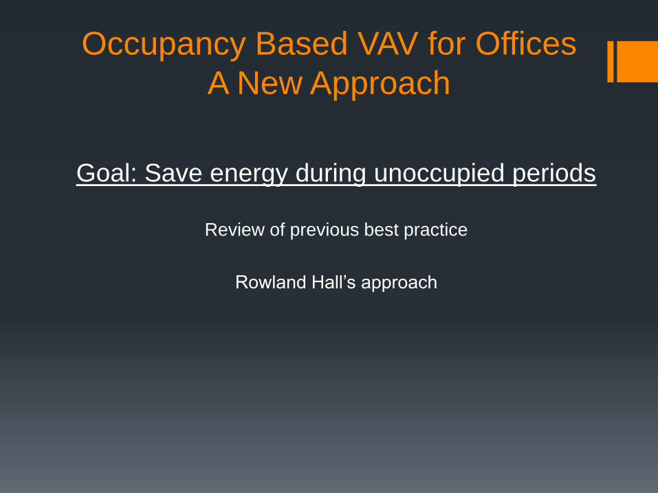
Occupancy Based VAV for Offices
A New Approach
Goal: Save energy during unoccupied periods
Review of previous best practice
Rowland Hall’s approach
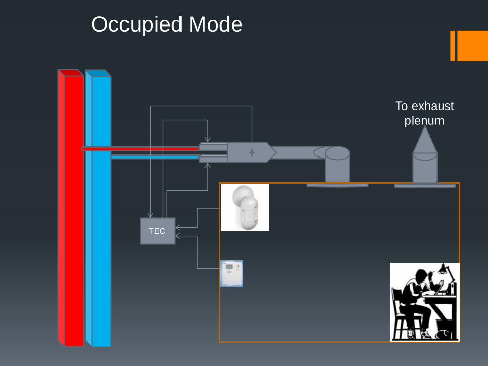
Occupied Mode
TEC
To exhaust
plenum
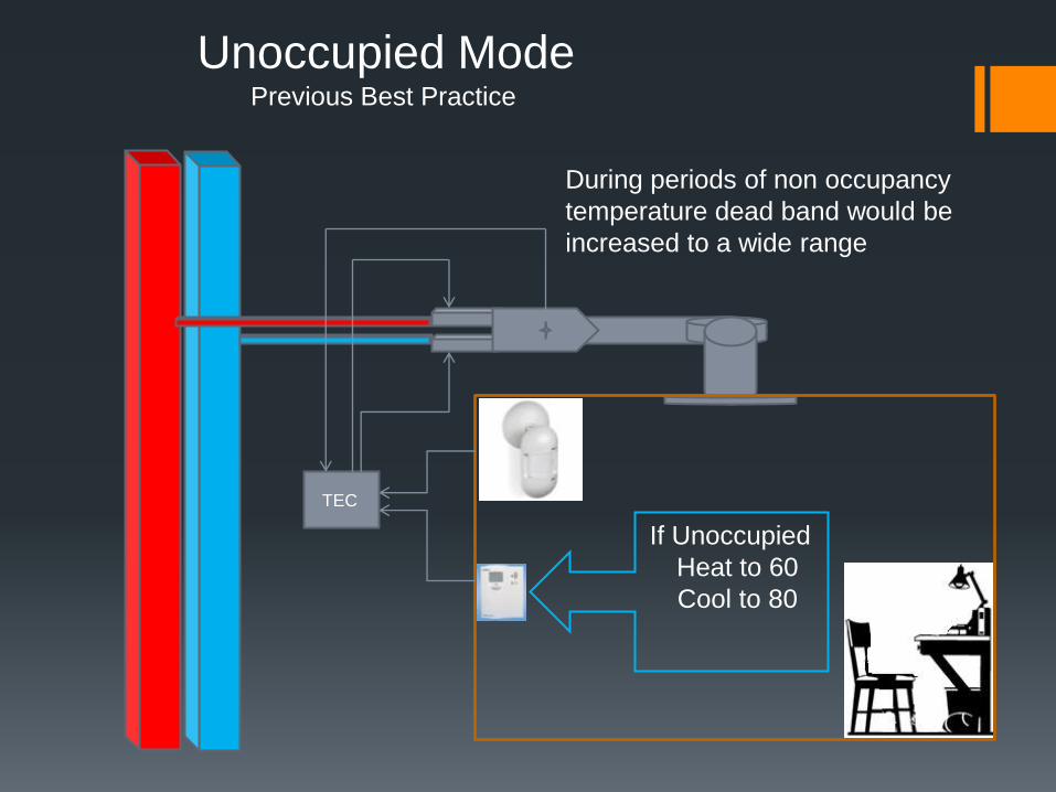
Unoccupied ModePrevious Best Practice
During periods of non occupancy
temperature dead band would be
increased to a wide range
If Unoccupied
Heat to 60
Cool to 80
TEC
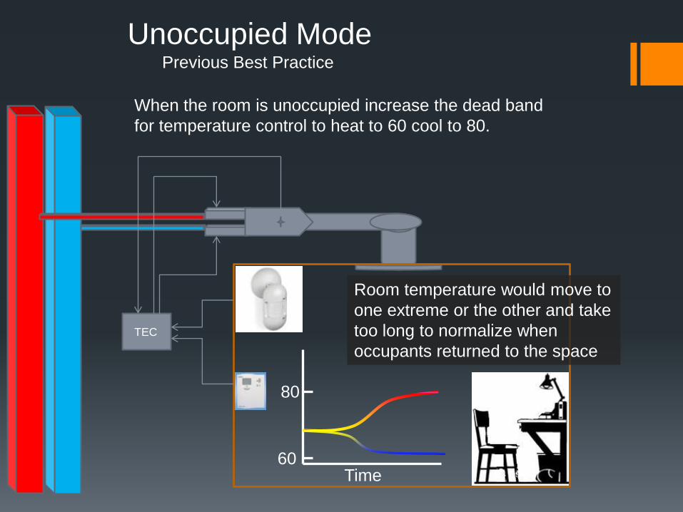
Unoccupied ModePrevious Best Practice
Room temperature would move to
one extreme or the other and take
too long to normalize when
occupants returned to the space
80
60Time
TEC
When the room is unoccupied increase the dead band
for temperature control to heat to 60 cool to 80.
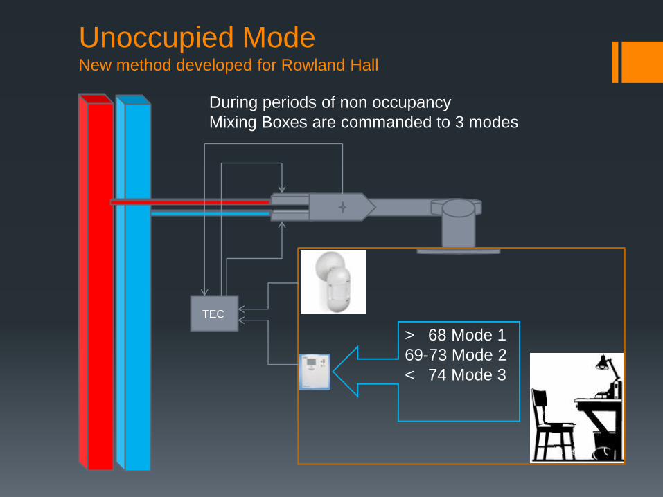
Unoccupied ModeNew method developed for Rowland Hall
During periods of non occupancy
Mixing Boxes are commanded to 3 modes
> 68 Mode 1
69-73 Mode 2
< 74 Mode 3
TEC
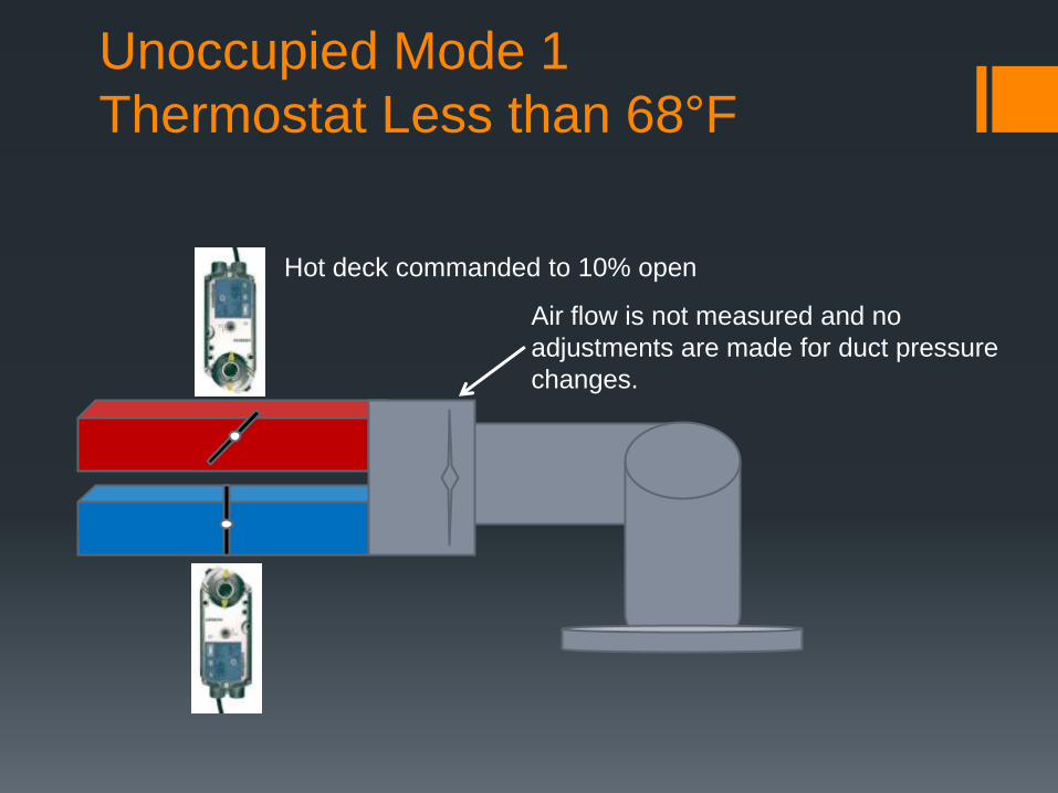
Unoccupied Mode 1
Thermostat Less than 68°F
Hot deck commanded to 10% open
Air flow is not measured and no
adjustments are made for duct pressure
changes.
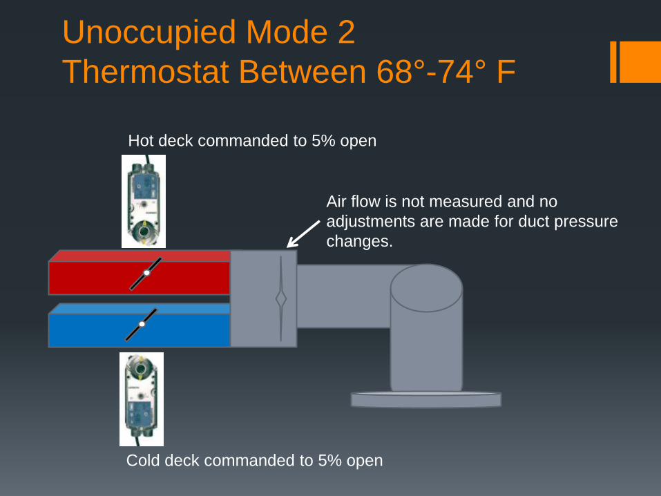
Unoccupied Mode 2
Thermostat Between 68°-74° F
Hot deck commanded to 5% open
Air flow is not measured and no
adjustments are made for duct pressure
changes.
Cold deck commanded to 5% open
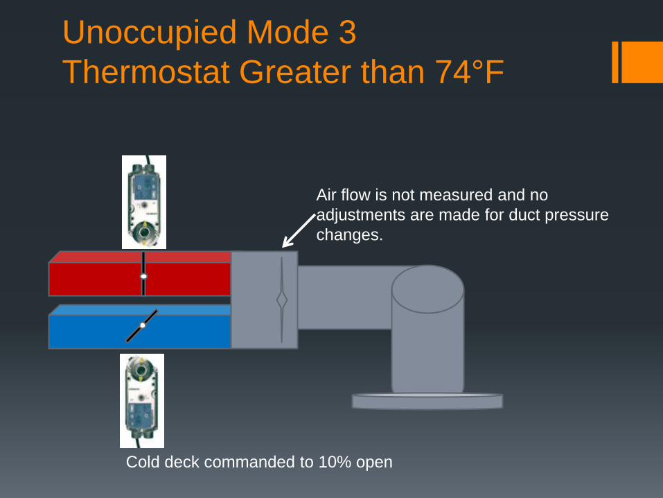
Unoccupied Mode 3
Thermostat Greater than 74°F
Cold deck commanded to 10% open
Air flow is not measured and no
adjustments are made for duct pressure
changes.
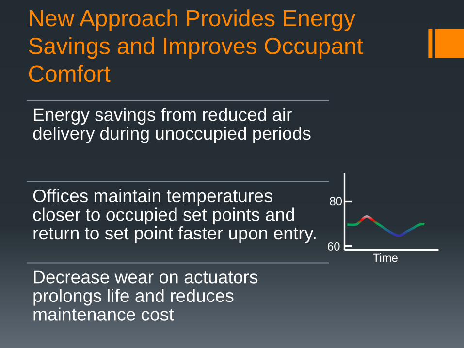
New Approach Provides Energy
Savings and Improves Occupant
Comfort
Energy savings from reduced air delivery during unoccupied periods
Offices maintain temperatures closer to occupied set points and return to set point faster upon entry.
Decrease wear on actuators prolongs life and reduces maintenance cost
80
60Time
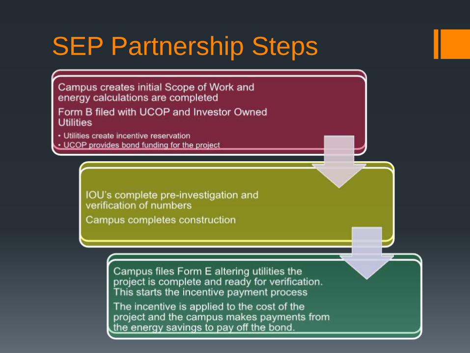
SEP Partnership Steps
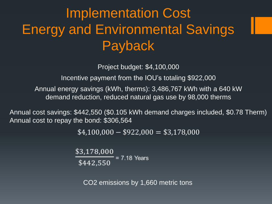
Implementation Cost
Energy and Environmental Savings
Payback
Project budget: $4,100,000
Annual energy savings (kWh, therms): 3,486,767 kWh with a 640 kW
demand reduction, reduced natural gas use by 98,000 therms
Annual cost savings: $442,550 ($0.105 kWh demand charges included, $0.78 Therm)
Annual cost to repay the bond: $306,564
CO2 emissions by 1,660 metric tons
Incentive payment from the IOU’s totaling $922,000
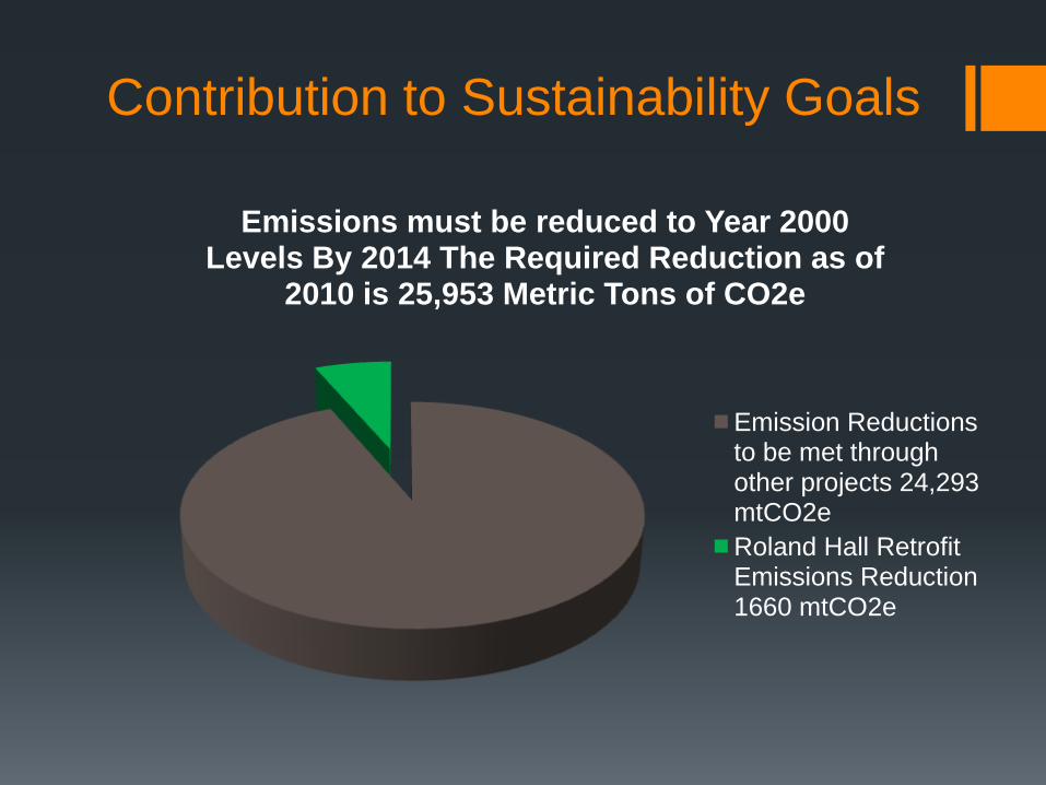
Contribution to Sustainability Goals
Emissions must be reduced to Year 2000 Levels By 2014 The Required Reduction as of
2010 is 25,953 Metric Tons of CO2e
Emission Reductions to be met through other projects 24,293 mtCO2e
Roland Hall Retrofit Emissions Reduction 1660 mtCO2e
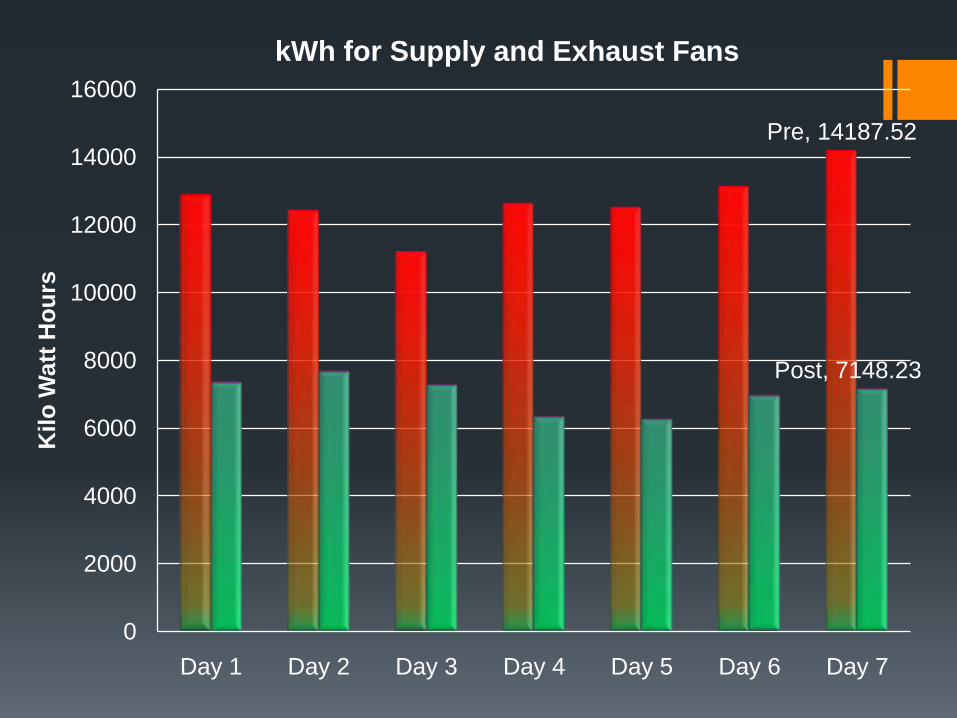
Pre, 14187.52
Post, 7148.23
0
2000
4000
6000
8000
10000
12000
14000
16000
Day 1 Day 2 Day 3 Day 4 Day 5 Day 6 Day 7
Kilo
Watt
Ho
urs
kWh for Supply and Exhaust Fans
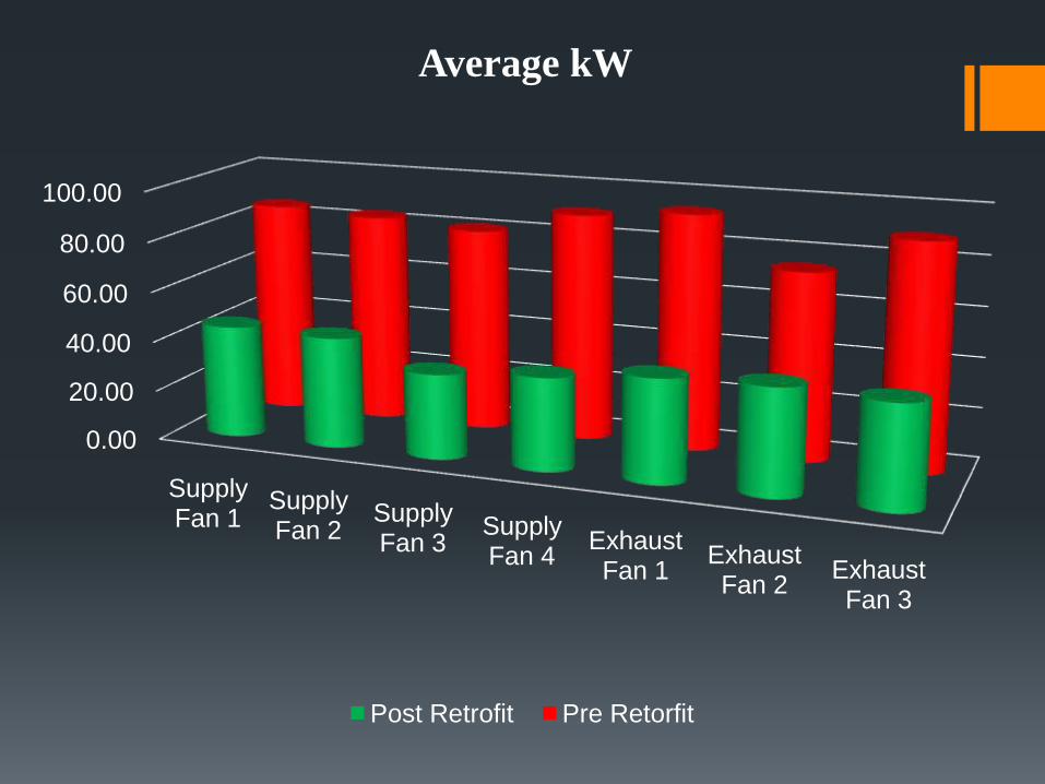
0.00
20.00
40.00
60.00
80.00
100.00
Supply Fan 1
Supply Fan 2
Supply Fan 3
Supply Fan 4
Exhaust Fan 1
Exhaust Fan 2
Exhaust Fan 3
Average kW
Post Retrofit Pre Retorfit
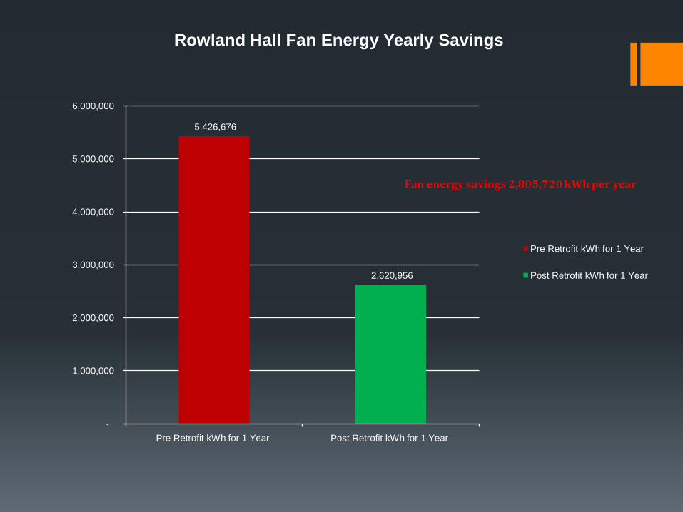
5,426,676
2,620,956
-
1,000,000
2,000,000
3,000,000
4,000,000
5,000,000
6,000,000
Pre Retrofit kWh for 1 Year Post Retrofit kWh for 1 Year
Rowland Hall Fan Energy Yearly Savings
Pre Retrofit kWh for 1 Year
Post Retrofit kWh for 1 Year

This concludes The American Institute of Architects
Continuing Education Systems Program


