
© K Bater 2009 1
R A D A RRYA 1 Day Course
RAdio Detection And Ranging
Skysail
Training
Keith Bater
© K Bater 2008 2© K Bater 2008
2
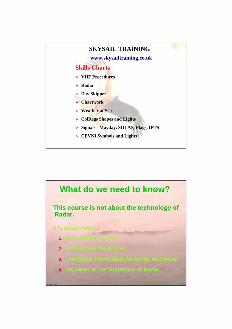
SKYSAIL TRAINING
Shorebased Courses
RYA Radar
Basic Navigation
Day Skipper
Yachtmaster
www.skysailtraining.co.uk
www.irpcs.com
© K Bater 2008 3© K Bater 2008
3
SKYSAIL TRAINING
Skills ChartsVHF Procedures
Radar
Day Skipper
Chartwork
Weather at Sea
ColRegs Shapes and Lights
Signals - Mayday, SOLAS, Flags, IPTS
CEVNI Symbols and Lights
www.skysailtraining.co.uk
© K Bater 2008 4© K Bater 2008
What do we need to know?
This course is not about the technology of Radar.
It is about how to:
1. Get a Radar picture
2. Understand the picture
3. Use Radar information for better decisions
4. Be aware of the limitations of Radar
© K Bater 2008 5
Plan for Today0915 Introductions
0925 History
0930 Why are we here? - MAIB Reports: Wahkuna & Ouzo Case Studies
0940 Principles
0950 The Radar simulator Exercise
1010 Switching on and setting up the radar set Exercise; Q&A
1045 Understanding and improving the radar picture Exercise
1115 Reflection and Radar Reflectors
1200 Relative Motion, collision avoidance
1230 LUNCH
1315 Collision avoidance with radar, plotting, MARPA Exercise
1430 Fixing Position and Pilotage by radar
1500 More collision exercises Exercise
1610 Uninstall simulator from program list
1615 Wrap up, feedback Discussion
1630 ish END
© K Bater 2008 6
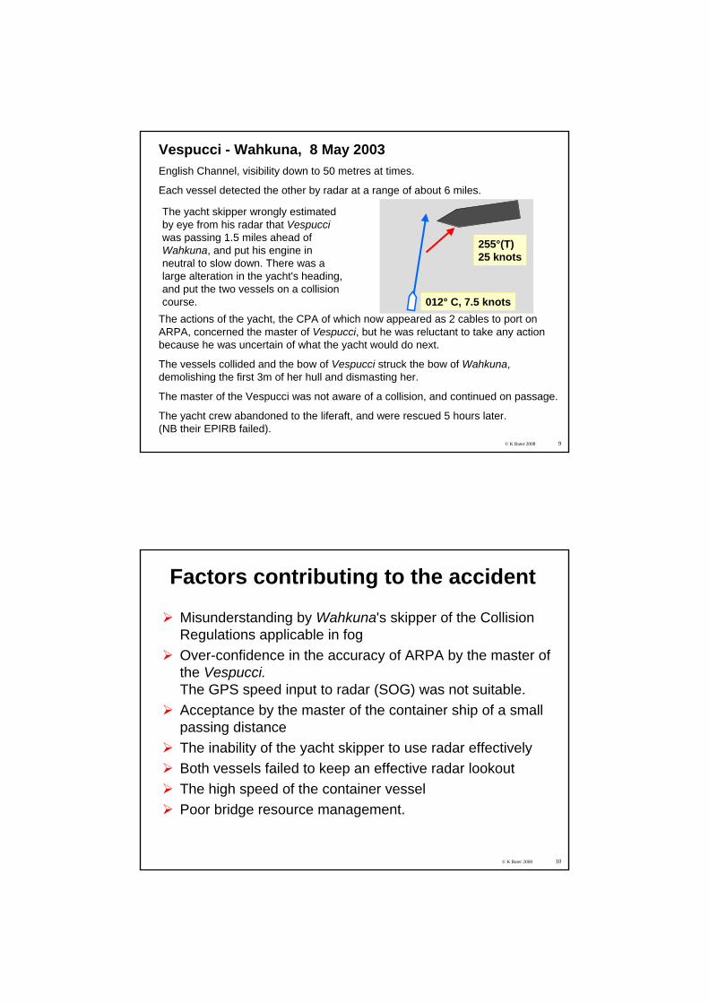
1. HISTORY1861 Maxwell’s theory1886 Hertz generated radio waves1904 Hülsmeyer’s 1st patent - anti collision1922 Marconi tested for ships1935 Watson-Watt implementation, closely
followed by German scientists.Initially ground stations, then ships and aircraft
1940 Cavity Magnetron - big breakthrough in size and accuracy 1990s Small craft installations
© K Bater 2008 7
MAIB Accident ReportYacht Wahkuna and MV Vespucci May 2003
© K Bater 2008 8© K Bater 2008
8
SY Wahkuna and MV VespucciMV Vespucci66,000 tons900 feet
Moody 47 Wahkuna 15 tons47 feet
© K Bater 2008 9
Vespucci - Wahkuna, 8 May 2003English Channel, visibility down to 50 metres at times.
Each vessel detected the other by radar at a range of about 6 miles.
012° C, 7.5 knots
255°(T)25 knots
The yacht skipper wrongly estimated by eye from his radar that Vespucci was passing 1.5 miles ahead of Wahkuna, and put his engine in neutral to slow down. There was a large alteration in the yacht's heading, and put the two vessels on a collision course.
The actions of the yacht, the CPA of which now appeared as 2 cables to port on ARPA, concerned the master of Vespucci, but he was reluctant to take any action because he was uncertain of what the yacht would do next.
The vessels collided and the bow of Vespucci struck the bow of Wahkuna, demolishing the first 3m of her hull and dismasting her.
The master of the Vespucci was not aware of a collision, and continued on passage.
The yacht crew abandoned to the liferaft, and were rescued 5 hours later.(NB their EPIRB failed).
© K Bater 2008 10
Factors contributing to the accident
Misunderstanding by Wahkuna's skipper of the Collision Regulations applicable in fogOver-confidence in the accuracy of ARPA by the master of the Vespucci.The GPS speed input to radar (SOG) was not suitable.Acceptance by the master of the container ship of a small passing distanceThe inability of the yacht skipper to use radar effectivelyBoth vessels failed to keep an effective radar lookoutThe high speed of the container vesselPoor bridge resource management.
© K Bater 2008 11
Ouzo - MAIB ReportWind SW F 5-6, waves 2 to 3 metres high
The 25 ft yacht Ouzo was not detected by the radars on board Pride of Bilbao due to:
The small radar cross section area of the yacht
The poor performance of the yacht’s radar reflector
The sea conditions
The use of auto sea clutter suppression
No use of periodic manual adjustment of the radar clutter controls to search for small targets
o There were also problems with the lookout’s night vision
Reflected radio waves
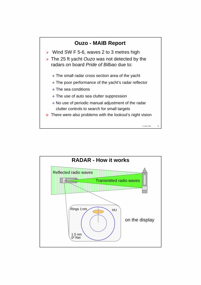
RADAR - How it works
Transmitted radio waves
on the display
1.5 nm0º Rel
HURings 1nm
© K Bater 2008 13
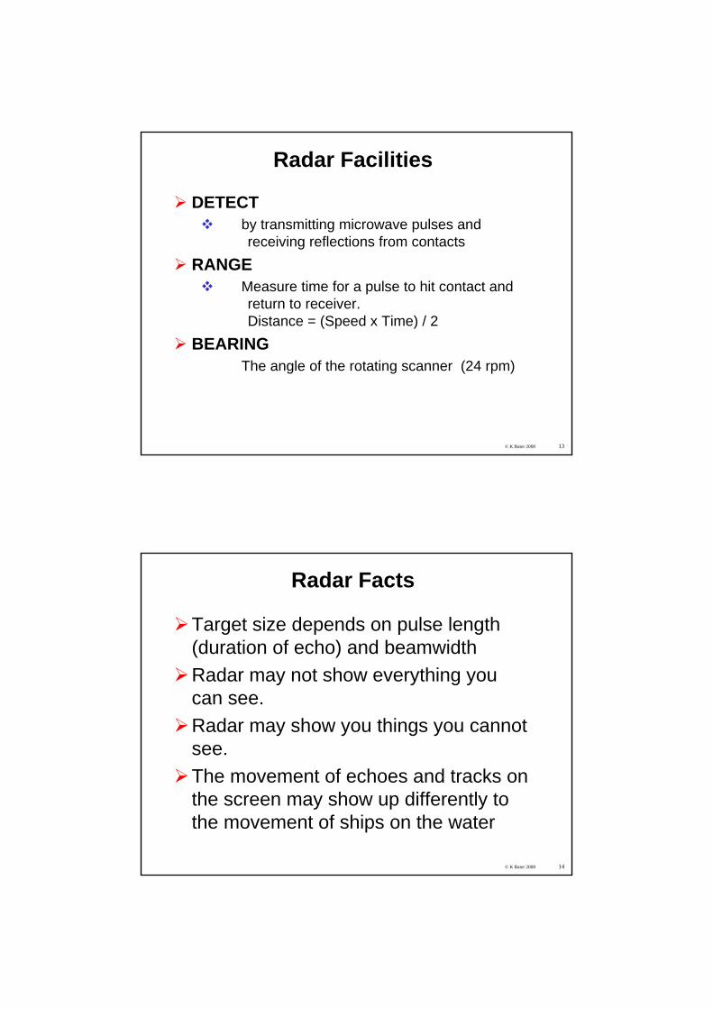
Radar Facilities
DETECTby transmitting microwave pulses and receiving reflections from contacts
RANGEMeasure time for a pulse to hit contact and return to receiver. Distance = (Speed x Time) / 2
BEARINGThe angle of the rotating scanner (24 rpm)
© K Bater 2008 14
Radar Facts
Target size depends on pulse length (duration of echo) and beamwidthRadar may not show everything you can see.Radar may show you things you cannot see.The movement of echoes and tracks on the screen may show up differently to the movement of ships on the water
© K Bater 2008 15
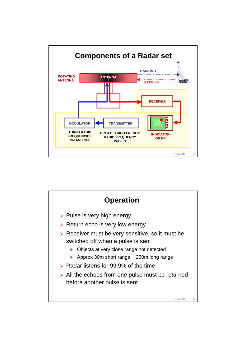
Components of a Radar set
ANTENNA
MODULATOR
TURNS RADIOFREQUENCIES
ON AND OFF
RECEIVER
TRANSMITTER
CREATES HIGH ENERGYRADIO FREQUENCY
WAVES
TRANSMIT
RECEIVE
ROTATINGANTENNA
INDICATOR-OR PPI
© K Bater 2008 16
Operation
Pulse is very high energyReturn echo is very low energyReceiver must be very sensitive, so it must be switched off when a pulse is sent
Objects at very close range not detectedApprox 30m short range, 250m long range
Radar listens for 99.9% of the timeAll the echoes from one pulse must be returned before another pulse is sent
© K Bater 2008 17
Definitions
Pulse - burst of transmitted microwave energyEcho - burst of reflected energyTarget - any object which returns an echoContact / blob - a target on the screen
Millisecond - 1 msec= 1/1000 of a second
Microsecond - 1 μsec = 1 millionth of a secondSpeed of pulse -162,000 nautical miles per second = 300 metres per μsec.
© K Bater 2008 18
AbbreviationsARPA Automatic Radar Plotting AidCPA Closest Point of ApproachContact Target on a radar screen (blob)EBL Electronic Bearing LineEcho Return from a targetFTC Fast Time Constant (Rain Clutter control)MARPA Mini Automatic Radar Plotting AidPRF Pulse Repetition FrequencyRacon Radar BeaconRCS Radar Cross SectionRTE Radar Target EnhancerS Band 3 GHz 10cm band - Ship radarSART Search and Rescue TransponderSTC Sensitivity Time Control Target Object which returns an echoTCPA Time to Closest Point of ApproachVRM Variable Range MarkerX Band 9.4GHz 3cm band - Yacht radar
© K Bater 2008 19
© K Bater 2008 20
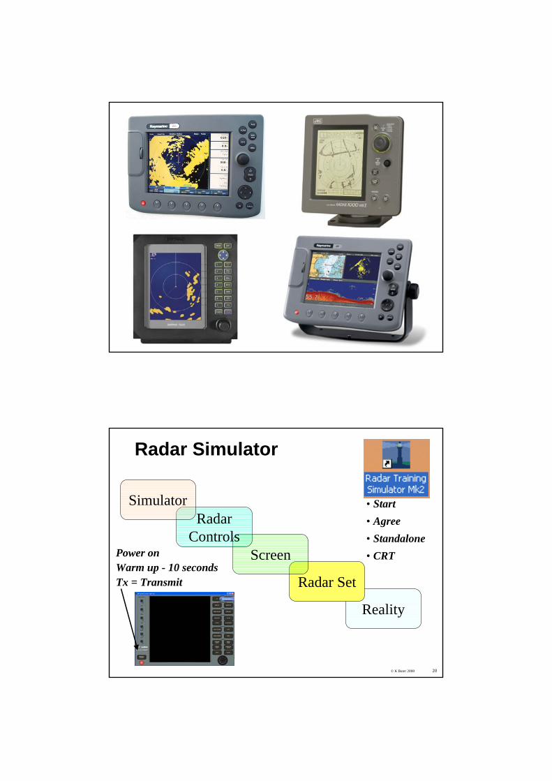
Radar Simulator
Reality
Radar Set
Screen
RadarControls
Simulator • Start• Agree• Standalone• CRTPower on
Warm up - 10 secondsTx = Transmit

© K Bater 2008 21© K Bater 2008
Radar SimulatorSelecting an exercise
Exercise ControlOpen Run
Speed up time
© K Bater 2008 22
Radar Simulator
Exercise ManagerVessel controlHeading / speed
© K Bater 2008 23
Simulator ExercisesExercise Targets
A Open water 1 ship, 1 buoy Collision? Stop exercise. Set up Wind, Sea Clutter & Rain control
B Open water 3
C Open water 1 ship, 4 buoys
D West Solent 1 ship dead ahead CPA 0.1M
E Portsmouth approaches 1 ship, forts
F Solent off Ryde harbour 2 ships, 4 buoys
G Needles - Calshot 2 ships. 2 buoys
Radar Shadow
RAIN and SEA CLUTTER Racon + Ship in rain Rain and Sea Clutter
31a Open water 1 @ 16kn CPA 1M ahead
31b Open water 1 Collision
31c Open water 1 Stbd beam 20kn Crossing ahead
31d Open water 1 Stationary
31e Open water 1 14kn CPA 0.3M long way ahead
Christchurch 3 point fix None
Congested harbour
© K Bater 2008 24
1. Switching on and setting upPower / transmit
Power - warm up time (2 minutes for magnetron)Standby (also Watch mode)Transmit - Tx
Main controls - B G R TBrightness of imageGain - amplifies the weak return signal, causes ‘speckle’.(Contrast - if present)Range - alters range rings and varies pulse length and interval.
Long range = long pulse at long intervals.Tuning - matches frequency of sent and received pulses.Need a target to tune on - use sea clutter
© K Bater 2008 25
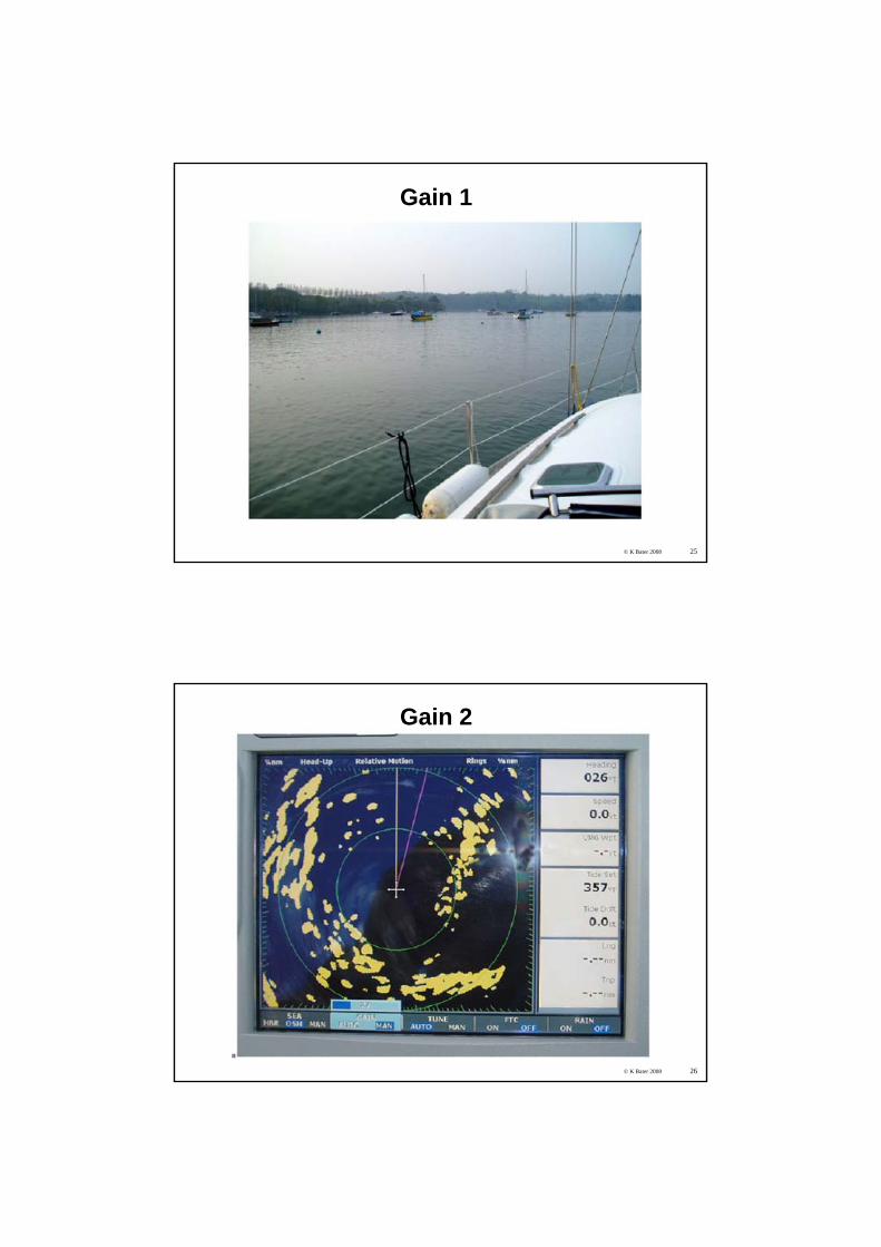
Gain 1
© K Bater 2008 26
Gain 2
© K Bater 2008 27
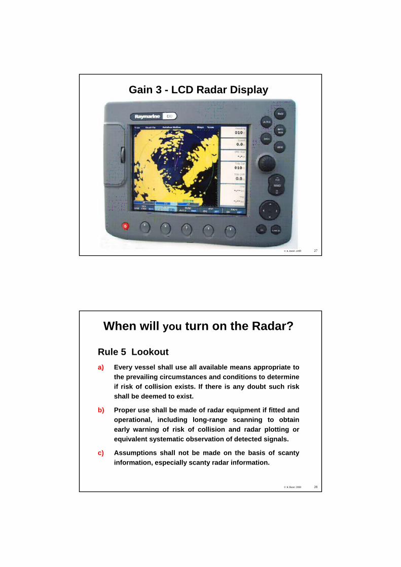
Gain 3 - LCD Radar Display
© K Bater 2008 28
When will you turn on the Radar?
Rule 5 Lookouta) Every vessel shall use all available means appropriate to
the prevailing circumstances and conditions to determine if risk of collision exists. If there is any doubt such risk shall be deemed to exist.
b) Proper use shall be made of radar equipment if fitted and operational, including long-range scanning to obtain early warning of risk of collision and radar plotting or equivalent systematic observation of detected signals.
c) Assumptions shall not be made on the basis of scanty information, especially scanty radar information.
© K Bater 2008 29
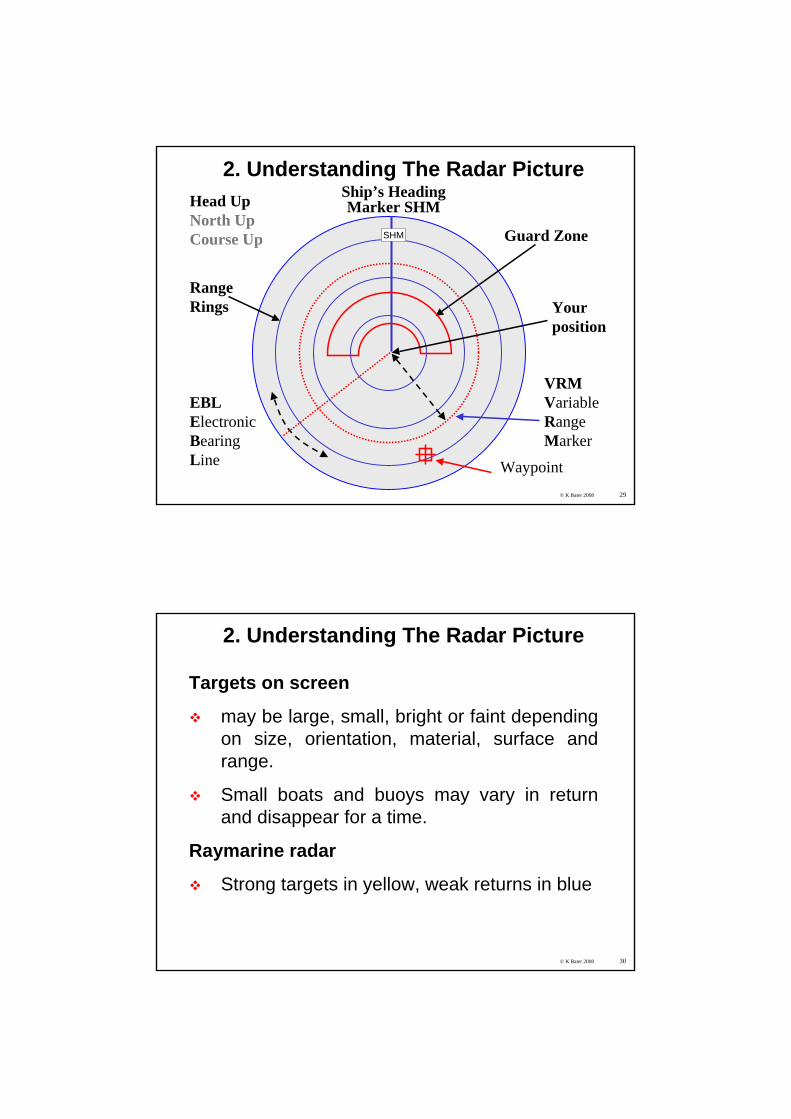
2. Understanding The Radar Picture
EBLElectronicBearingLine
VRMVariableRangeMarker
Guard Zone
Ship’s HeadingMarker SHM
RangeRings
Head UpNorth UpCourse Up
Waypoint
SHM
Yourposition
© K Bater 2008 30
2. Understanding The Radar Picture
Targets on screen
may be large, small, bright or faint depending on size, orientation, material, surface and range.
Small boats and buoys may vary in return and disappear for a time.
Raymarine radar
Strong targets in yellow, weak returns in blue
© K Bater 2008 31
2. Understanding The Radar Picture
Target controlsInterference Rejection - reduces mutual radar interference when two boats with radar are close. Normally switched on, but if switched off will show the presence of the other boats.
Expansion or Echo Stretch- expands target returns; easier to see target but reduces range accuracy.
Wakes - shows approx direction and speed of a moving target. Duration of wakes may be varied.
© K Bater 2008 32
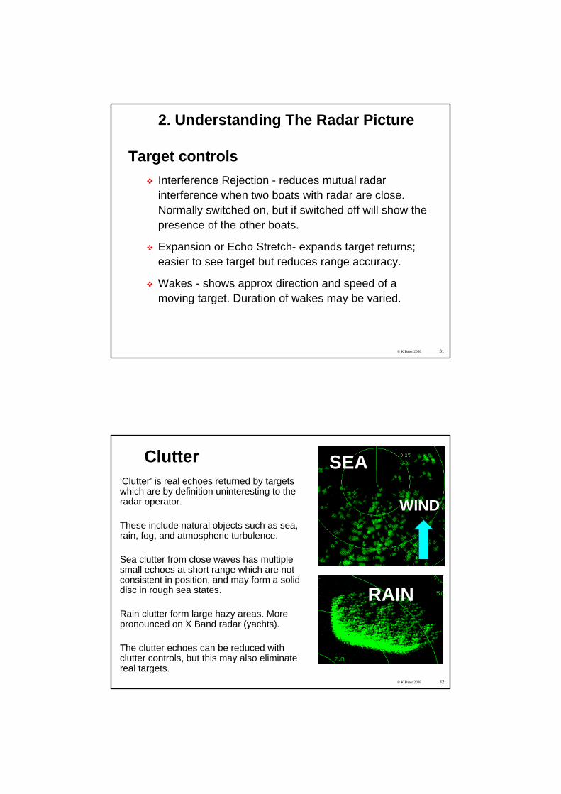
Clutter‘Clutter’ is real echoes returned by targets which are by definition uninteresting to the radar operator.
These include natural objects such as sea, rain, fog, and atmospheric turbulence.
Sea clutter from close waves has multiple small echoes at short range which are not consistent in position, and may form a solid disc in rough sea states.
Rain clutter form large hazy areas. More pronounced on X Band radar (yachts).
The clutter echoes can be reduced with clutter controls, but this may also eliminate real targets.
RAIN
SEA
WIND
© K Bater 2008 33
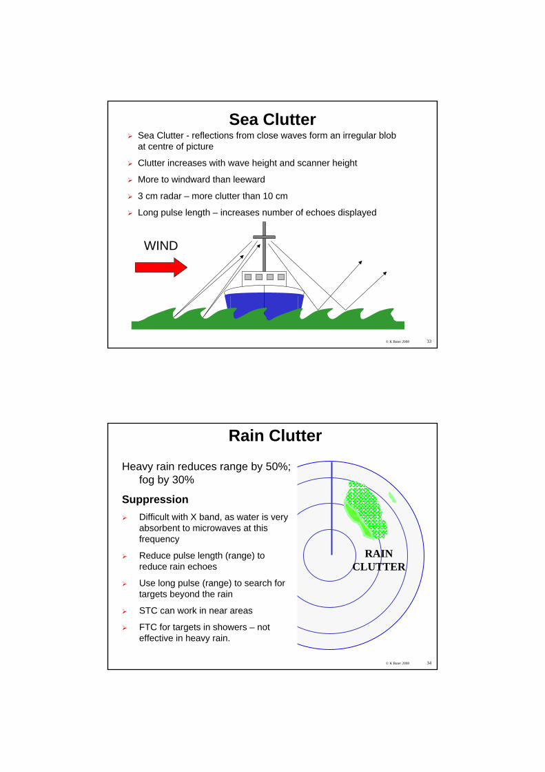
Sea ClutterSea Clutter - reflections from close waves form an irregular blob at centre of picture
Clutter increases with wave height and scanner height
More to windward than leeward
3 cm radar – more clutter than 10 cm
Long pulse length – increases number of echoes displayed
WIND
© K Bater 2008 34
Rain Clutter
RAINCLUTTER
Heavy rain reduces range by 50%;fog by 30%
SuppressionDifficult with X band, as water is very absorbent to microwaves at this frequency
Reduce pulse length (range) to reduce rain echoes
Use long pulse (range) to search for targets beyond the rain
STC can work in near areas
FTC for targets in showers – not effective in heavy rain.
© K Bater 2008 35
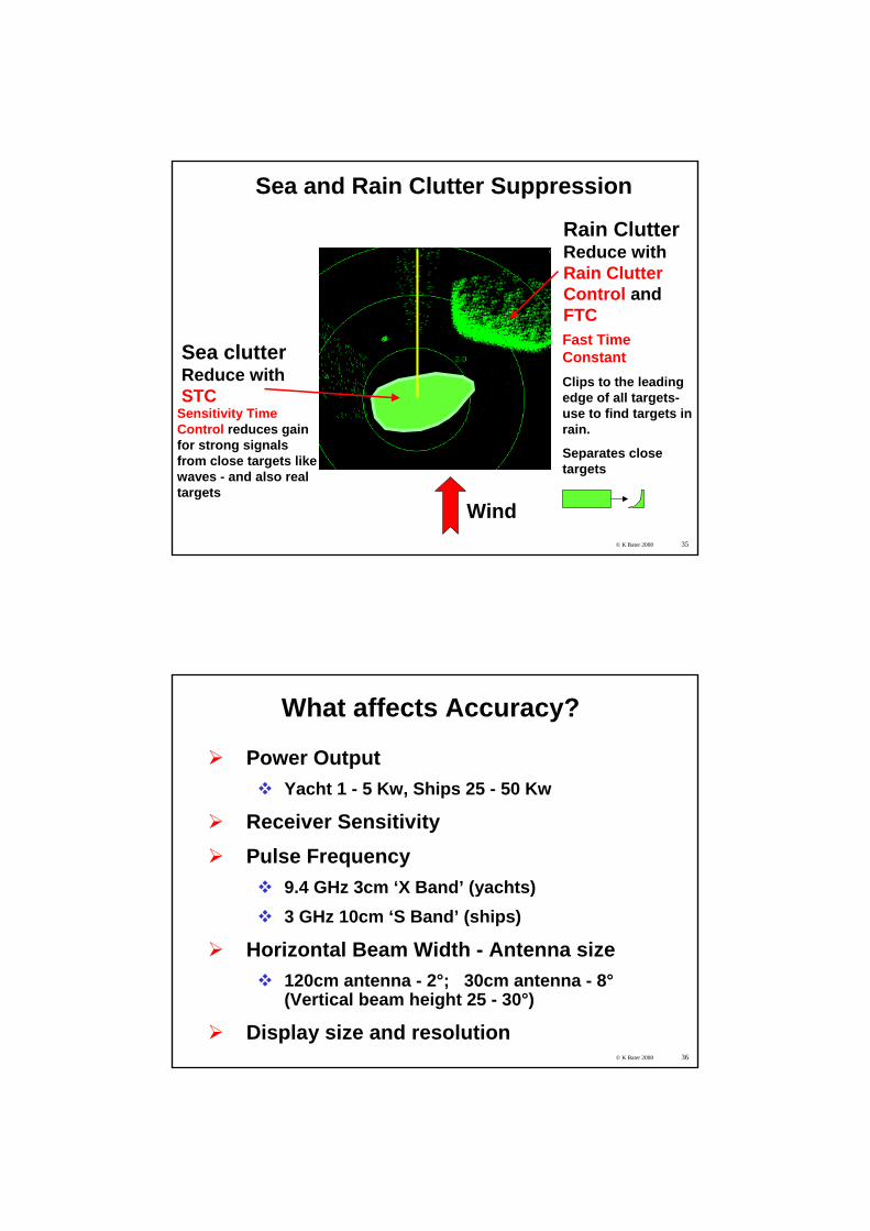
Sea and Rain Clutter Suppression
Sea clutter Reduce with STC
Rain ClutterReduce with Rain ClutterControl and FTCFOG
Sensitivity Time Control reduces gain for strong signals from close targets like waves - and also real targets
Fast Time ConstantClips to the leading edge of all targets-use to find targets in rain.
Separates close targets
Wind
SEA CLUTTER
© K Bater 2008 36
What affects Accuracy?
Power OutputYacht 1 - 5 Kw, Ships 25 - 50 Kw
Receiver SensitivityPulse Frequency
9.4 GHz 3cm ‘X Band’ (yachts) 3 GHz 10cm ‘S Band’ (ships)
Horizontal Beam Width - Antenna size120cm antenna - 2°; 30cm antenna - 8°(Vertical beam height 25 - 30°)
Display size and resolution
© K Bater 2008 37
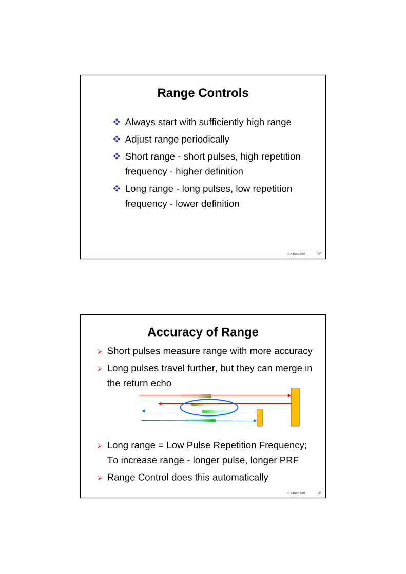
Range Controls
Always start with sufficiently high range
Adjust range periodically
Short range - short pulses, high repetition frequency - higher definition
Long range - long pulses, low repetition frequency - lower definition
© K Bater 2008 38
Accuracy of RangeShort pulses measure range with more accuracy
Long pulses travel further, but they can merge in the return echo
Long range = Low Pulse Repetition Frequency; To increase range - longer pulse, longer PRF
Range Control does this automatically
© K Bater 2008 39
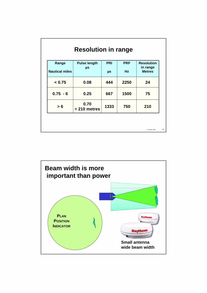
Resolution in range
Range
Nautical miles
Pulse lengthµs
PRI
µs
PRF
Hz
Resolution in rangeMetres
< 0.75 0.08 444 2250 24
0.75 - 6 0.25 667 1500 75
> 6 0.70= 210 metres 1333 750 210
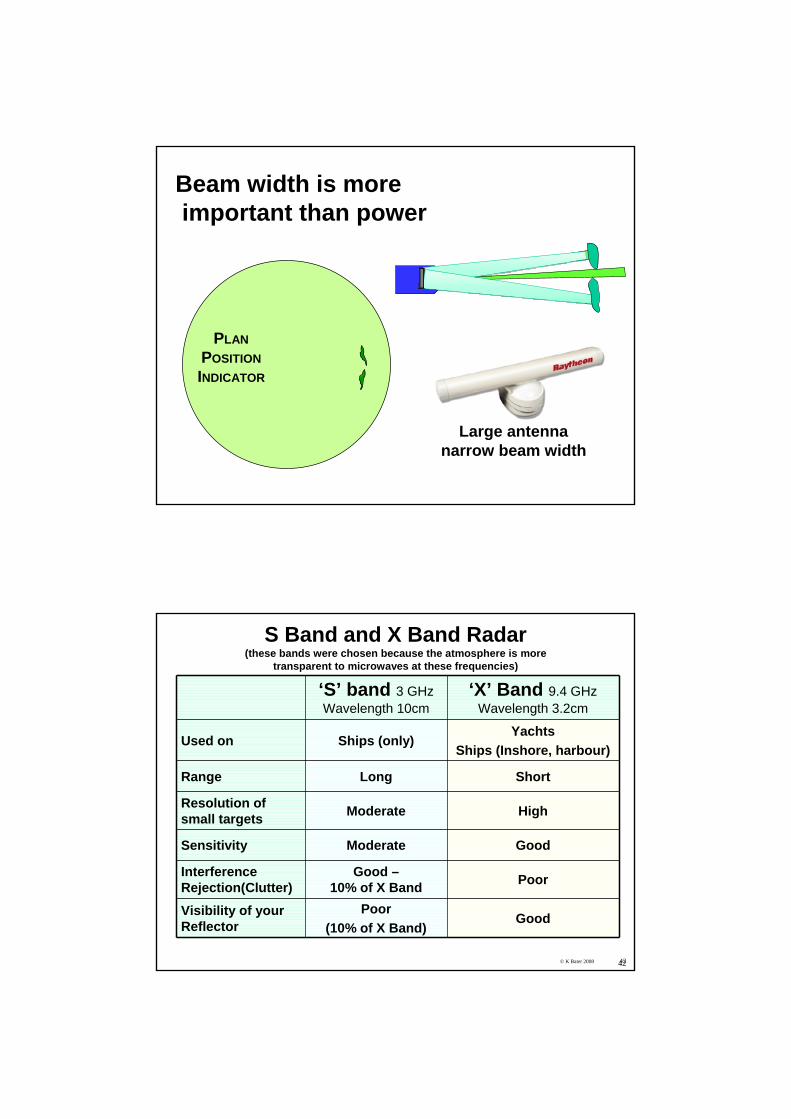
Beam width is moreimportant than power
PLANPOSITIONINDICATOR
Small antennawide beam width
PLANPOSITIONINDICATOR
Beam width is moreimportant than power
Large antennanarrow beam width
© K Bater 2008 4242
S Band and X Band Radar(these bands were chosen because the atmosphere is more
transparent to microwaves at these frequencies)
‘S’ band 3 GHzWavelength 10cm
‘X’ Band 9.4 GHzWavelength 3.2cm
Used on Ships (only)Yachts
Ships (Inshore, harbour)
Range Long Short
Resolution of small targets Moderate High
Sensitivity Moderate Good
InterferenceRejection(Clutter)
Good –10% of X Band Poor
Visibility of your Reflector
Poor(10% of X Band)
Good
© K Bater 2008 43
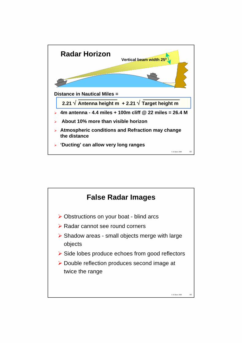
Radar Horizon
Distance in Nautical Miles =
2.21 √ Antenna height m + 2.21 √ Target height m
4m antenna - 4.4 miles + 100m cliff @ 22 miles = 26.4 M
About 10% more than visible horizon
Atmospheric conditions and Refraction may change the distance
‘Ducting’ can allow very long ranges
Vertical beam width 25º
© K Bater 2008 44
False Radar Images
Obstructions on your boat - blind arcs
Radar cannot see round corners
Shadow areas - small objects merge with large objects
Side lobes produce echoes from good reflectors
Double reflection produces second image at twice the range
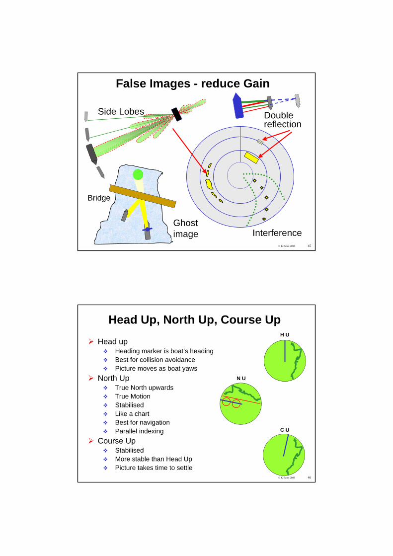
© K Bater 2008 45
Interference
Double reflection
Side Lobes
Ghostimage
Bridge
False Images - reduce Gain
© K Bater 2008 46
Head Up, North Up, Course UpHead up
Heading marker is boat’s headingBest for collision avoidancePicture moves as boat yaws
North UpTrue North upwardsTrue MotionStabilisedLike a chartBest for navigationParallel indexing
Course UpStabilisedMore stable than Head UpPicture takes time to settle
H U
N U
C U
© K Bater 2008 47
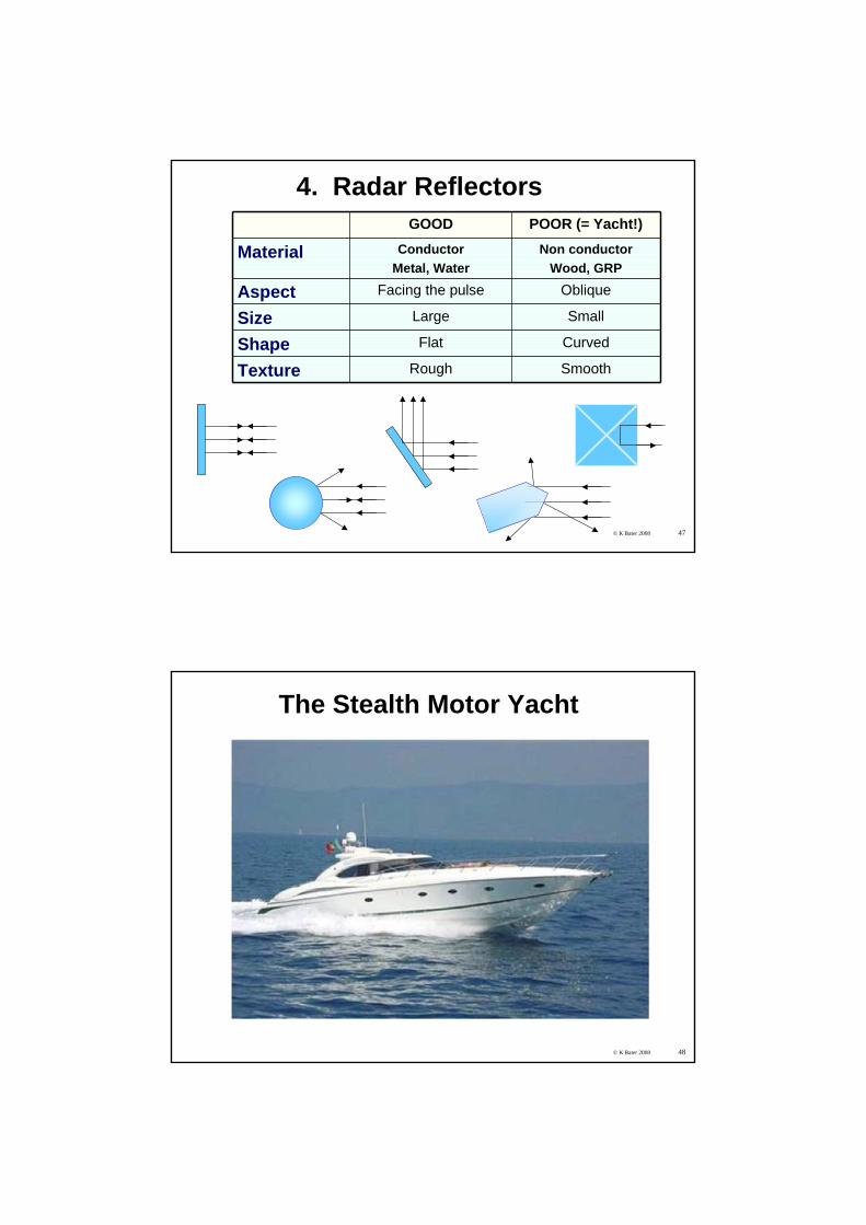
GOOD POOR (= Yacht!)
Material ConductorMetal, Water
Non conductorWood, GRP
Aspect Facing the pulse Oblique
Size Large Small
Shape Flat Curved
Texture Rough Smooth
4. Radar Reflectors
© K Bater 2008 48
The Stealth Motor Yacht
© K Bater 2008 49
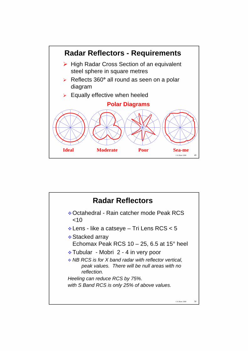
Radar Reflectors - RequirementsHigh Radar Cross Section of an equivalent steel sphere in square metresReflects 360° all round as seen on a polar diagramEqually effective when heeled
Ideal Moderate Sea-me
Polar Diagrams
Poor
© K Bater 2008 50
Radar ReflectorsOctahedral - Rain catcher mode Peak RCS <10 Lens - like a catseye – Tri Lens RCS < 5Stacked arrayEchomax Peak RCS 10 – 25, 6.5 at 15° heelTubular - Mobri 2 - 4 in very poorNB RCS is for X band radar with reflector vertical,
peak values. There will be null areas with no reflection.
Heeling can reduce RCS by 75%.with S Band RCS is only 25% of above values.
© K Bater 2008 51
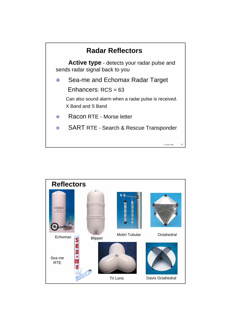
Radar ReflectorsActive type - detects your radar pulse and
sends radar signal back to you
Sea-me and Echomax Radar TargetEnhancers: RCS = 63
Can also sound alarm when a radar pulse is received. X Band and S Band
Racon RTE - Morse letter
SART RTE - Search & Rescue Transponder
Echomax
Davis Octahedral
Mobri Tubular
Reflectors
Tri Lens
Octahedral
Sea meRTE
Blipper
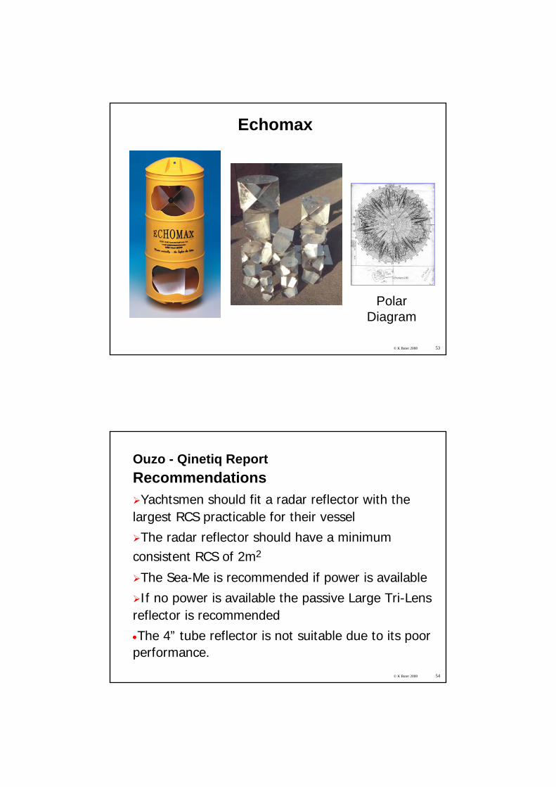
© K Bater 2008 53
Echomax
PolarDiagram
© K Bater 2008 54
Ouzo - Qinetiq ReportRecommendationsYachtsmen should fit a radar reflector with the
largest RCS practicable for their vessel
The radar reflector should have a minimum consistent RCS of 2m2
The Sea-Me is recommended if power is available
If no power is available the passive Large Tri-Lens reflector is recommended
•The 4” tube reflector is not suitable due to its poor performance.
© K Bater 2008 55
There is no substitute for size when it comes to radar reflectors. Devices with smaller size and lower windage simply don’t work as well.Passive reflectors are no more than marginally useful offshore if only S-band is used, except perhaps in calm sea conditions.Angle of heel is critical.OUZO – (octahedral?) at best a 50% probability that the ship would detect Ouzo on the radar at close range, even on X-BandLook for ISO 8729 in manufacturers’ specifications (Echomax)
Reflectors - Conclusions
© K Bater 2008 56
The revised ISO standard will result from the new IMO requirement This new IMO resolution recognises that consistency of response is more effective in raising the probability of radar detection than single high peaks. This is defined as a Stated Performance Level (SPL) and is required to be maintained at up to 10 or 20 degrees of heel (two classes recognising the stability differences of power and sailing vessels)
Reflectors - Conclusions
© K Bater 2008 57
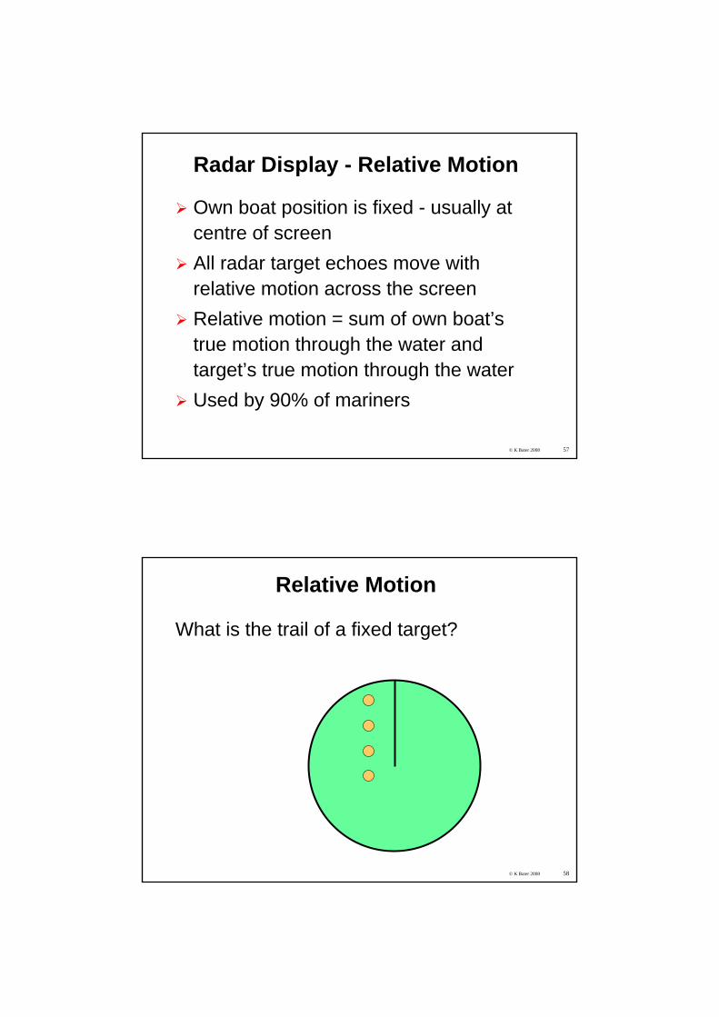
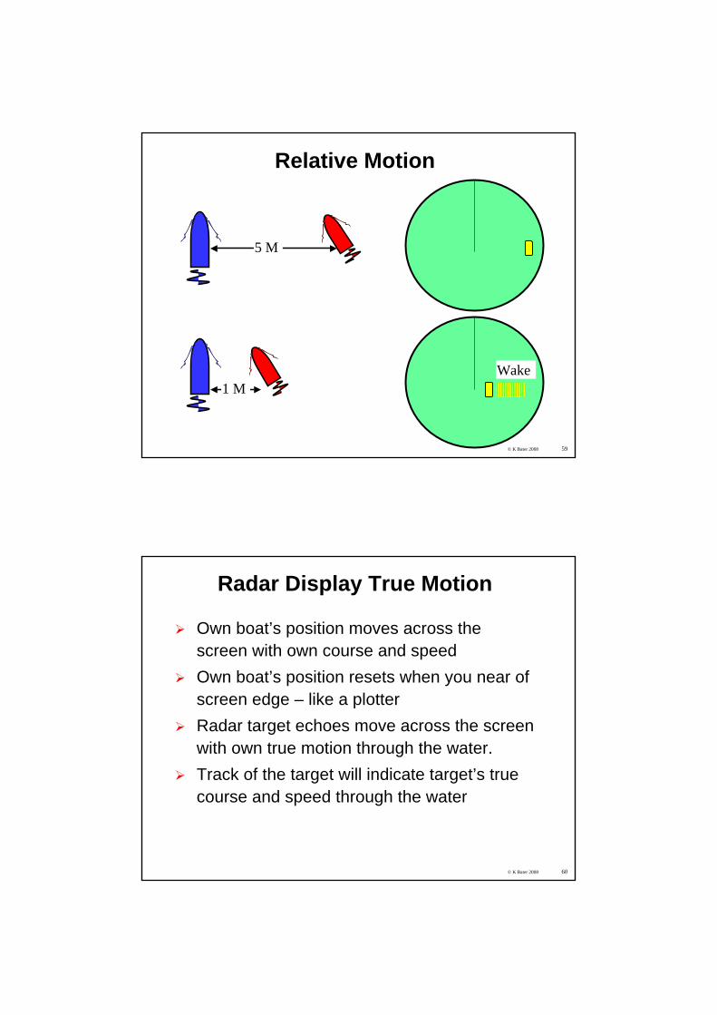
Radar Display - Relative Motion
Own boat position is fixed - usually at centre of screenAll radar target echoes move with relative motion across the screenRelative motion = sum of own boat’s true motion through the water and target’s true motion through the waterUsed by 90% of mariners
© K Bater 2008 58
Relative Motion
What is the trail of a fixed target?
© K Bater 2008 59
Relative Motion
1 M
5 M
Wake
© K Bater 2008 60
Radar Display True Motion
Own boat’s position moves across the screen with own course and speedOwn boat’s position resets when you near of screen edge – like a plotterRadar target echoes move across the screen with own true motion through the water.Track of the target will indicate target’s true course and speed through the water
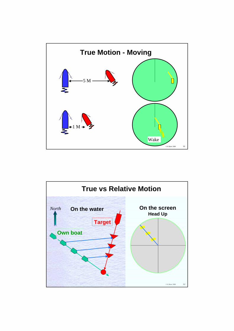
© K Bater 2008 61
True Motion - Moving
1 M
5 M
Wake
© K Bater 2008 62© K Bater 2008
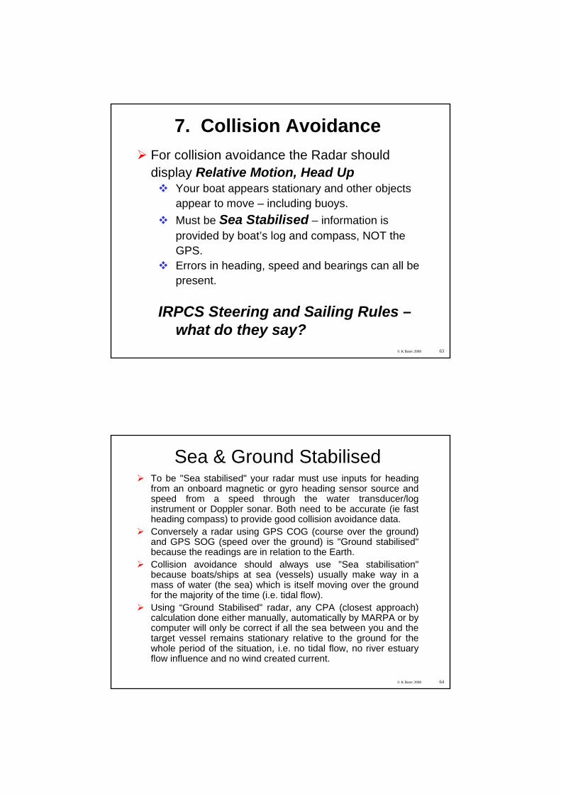
True vs Relative Motion
On the water On the screenHead Up
Target
Own boat
North
© K Bater 2008 63
7. Collision AvoidanceFor collision avoidance the Radar should display Relative Motion, Head Up
Your boat appears stationary and other objects appear to move – including buoys.Must be Sea Stabilised – information is provided by boat’s log and compass, NOT the GPS.Errors in heading, speed and bearings can all be present.
IRPCS Steering and Sailing Rules –what do they say?
© K Bater 2008 64
Sea & Ground StabilisedTo be "Sea stabilised" your radar must use inputs for heading from an onboard magnetic or gyro heading sensor source and speed from a speed through the water transducer/log instrument or Doppler sonar. Both need to be accurate (ie fast heading compass) to provide good collision avoidance data.Conversely a radar using GPS COG (course over the ground) and GPS SOG (speed over the ground) is "Ground stabilised" because the readings are in relation to the Earth.Collision avoidance should always use "Sea stabilisation" because boats/ships at sea (vessels) usually make way in a mass of water (the sea) which is itself moving over the ground for the majority of the time (i.e. tidal flow). Using “Ground Stabilised" radar, any CPA (closest approach) calculation done either manually, automatically by MARPA or by computer will only be correct if all the sea between you and thetarget vessel remains stationary relative to the ground for the whole period of the situation, i.e. no tidal flow, no river estuary flow influence and no wind created current.
© K Bater 2008 65
Do you have a sea-stabilised radar?On a day when there is no wind:1. Choose somewhere where the tide is running.2. Target a fixed object, such as a buoy.3. Stop the boat and drift with the water.4. Locate the buoy on the radar, and choose a range
scale to fit. Acquire MARPA target, and wait.
If MARPA shows the buoy is stationary (or virtually stationary given instrumentation errors), and the radar shows an apparent speed for your vessel, the radar is ground stabilised.If MARPA shows that the buoy appears to be moving at the speed of the tide, but in the opposite direction to the tide, then you are sea stabilised, which is the correct setting to run MARPA for collision avoidance. The MARPA data box should detail this info as well
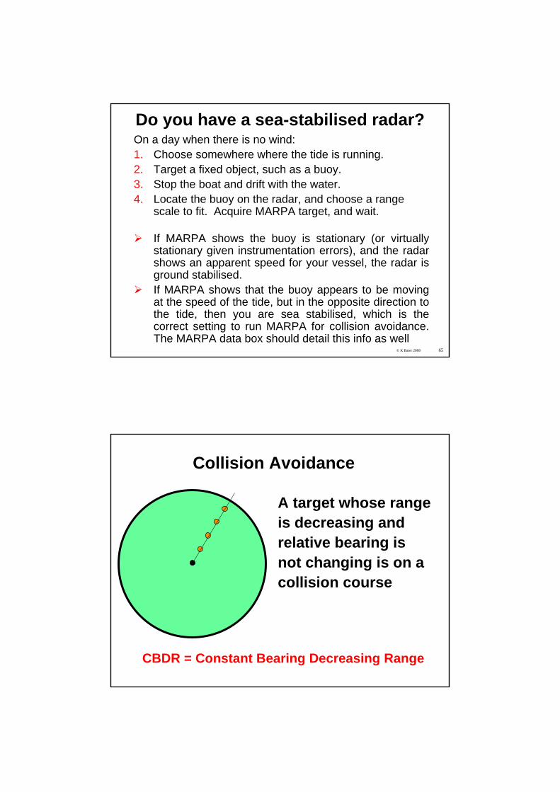
Collision Avoidance
A target whose rangeis decreasing andrelative bearing isnot changing is on acollision course
CBDR = Constant Bearing Decreasing Range
CPA
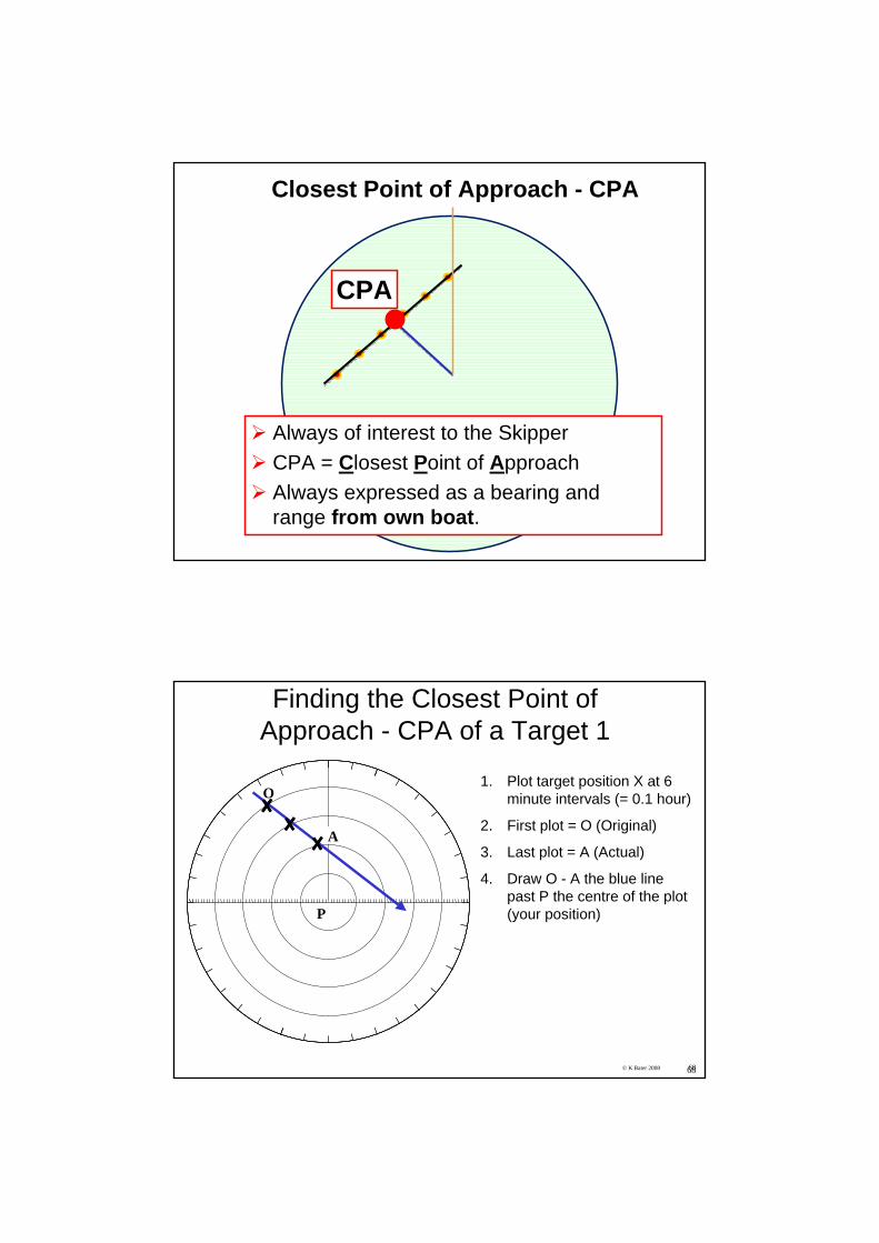
Closest Point of Approach - CPA
Always of interest to the SkipperCPA = Closest Point of ApproachAlways expressed as a bearing and range from own boat.
© K Bater 2008 6868
Finding the Closest Point of Approach - CPA of a Target 1
1. Plot target position X at 6 minute intervals (= 0.1 hour)
2. First plot = O (Original)
3. Last plot = A (Actual)
4. Draw O - A the blue line past P the centre of the plot (your position)
O
A
P
© K Bater 2008 69
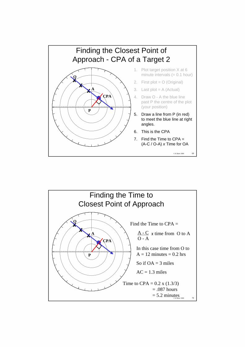
Finding the Closest Point of Approach - CPA of a Target 2
1. Plot target position X at 6 minute intervals (= 0.1 hour)
2. First plot = O (Original)
3. Last plot = A (Actual)
4. Draw O - A the blue line past P the centre of the plot (your position)
5. Draw a line from P (in red) to meet the blue line at right angles.
6. This is the CPA
7. Find the Time to CPA = (A-C / O-A) x Time for OA
O
A
P
CPA
© K Bater 2008 70
Finding the Time toClosest Point of Approach
Find the Time to CPA =
A - CO - A
X time from O to A
In this case time from O to A = 12 minutes = 0.2 hrs
So if OA = 3 miles
AC = 1.3 miles
O
A
P
CPA
Time to CPA = 0.2 x (1.3/3)= .087 hours= 5.2 minutes
© K Bater 2008 71
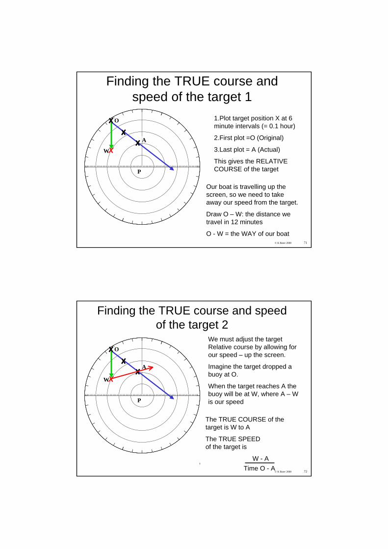
Finding the TRUE course and speed of the target 1
1.Plot target position X at 6 minute intervals (= 0.1 hour)
2.First plot =O (Original)
3.Last plot = A (Actual)
This gives the RELATIVE COURSE of the target
Our boat is travelling up the screen, so we need to take away our speed from the target.
Draw O – W: the distance we travel in 12 minutes
O - W = the WAY of our boat
O
A
P
WX
© K Bater 2008 72
Finding the TRUE course and speed of the target 2
O
A
P
WX
The TRUE COURSE of the target is W to A
The TRUE SPEEDof the target is
W - ATime O - A
We must adjust the target Relative course by allowing for our speed – up the screen.
Imagine the target dropped a buoy at O.
When the target reaches A the buoy will be at W, where A – W is our speed
© K Bater 2008 73
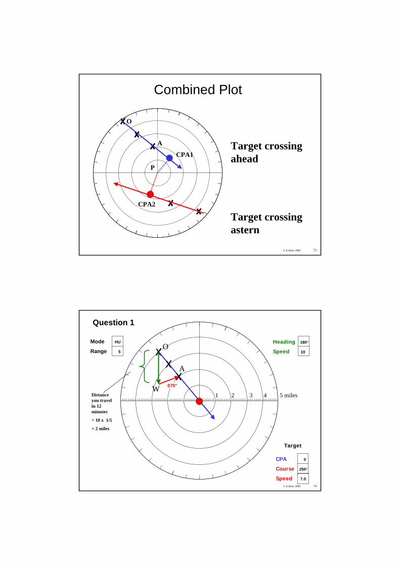
Combined Plot
Target crossing ahead
Target crossing astern
O
A
P
CPA1
CPA2
© K Bater 2008 74
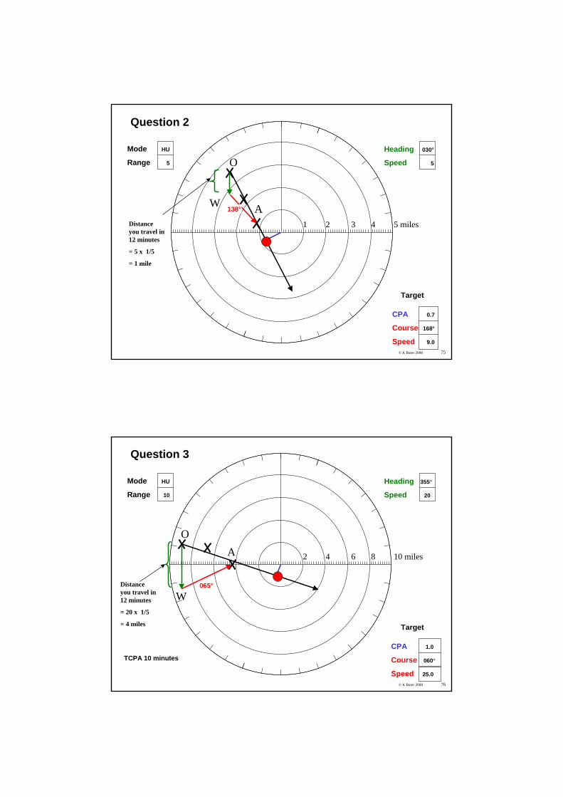
Mode HU
Range 5
Heading 180°
Speed 10
Question 1
CPA 0
Course 250°
Speed 7.0
Target
Distance you travel in 12 minutes
= 10 x 1/5
= 2 miles
W
O
A
070°
1 2 3 4 5 miles
© K Bater 2008 75
Mode HU
Range 5
Heading 030°
Speed 5
Question 2
CPA 0.7
Course 168°
Speed 9.0
Target
Distance you travel in 12 minutes
= 5 x 1/5
= 1 mile
W
O
A138°
1 2 3 4 5 miles
© K Bater 2008 76
W
OA
Mode HU
Range 10
Heading 355°
Speed 20
Question 3
CPA 1.0
Course 060°
Speed 25.0
Target
065°
TCPA 10 minutes
2 4 6 8 10 miles
Distance you travel in 12 minutes
= 20 x 1/5
= 4 miles
© K Bater 2008 77
W
O
A
Mode HU
Range 10
Heading 355°
Speed 20
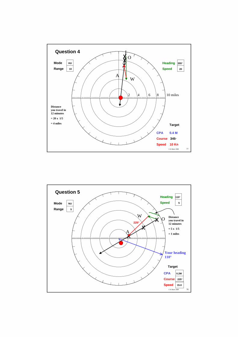
Question 4
CPA 0.4 M
Course 345°
Speed 10 Kn
Target
2 4 6 8 10 miles
Distance you travel in 12 minutes
= 20 x 1/5
= 4 miles
© K Bater 2008 78
Mode NU
Range 5
Heading 110°
Speed 5
Question 5
CPA 0.2M
Course 225°
Speed 15.0
Target
W O
A
225°
Distance you travel in 12 minutes
= 5 x 1/5
= 1 miles
Your heading110°
© K Bater 2008 79
O
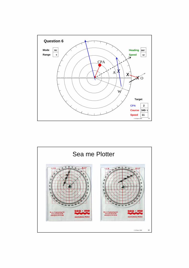
Mode NU
Range 5
Heading 060°
Speed 12
Question 6
CPA 2
Course 345° T
Speed 11
Target
W
A
CPA
© K Bater 2008 80
Sea me Plotter
Rule 5 Lookouta) Every vessel shall use all available means appropriate to
the prevailing circumstances and conditions to determine if risk of collision exists. If there is any doubt such risk shall be deemed to exist.
b) Proper use shall be made of radar equipment if fitted and operational, including long-range scanning to obtain early warning of risk of collision and radar plotting or equivalent systematic observation of detected signals.
c) Assumptions shall not be made on the basis of scanty information, especially scanty radar information.
IRPCS Steering and Sailing Rules
RULE 6 Safe SpeedEvery vessel shall at all times proceed at a safe speedIn determining a safe speed the following factors shall be among those taken
into account ….depth, traffic, hazards, sea state etc.
Additionally, by vessels with operational radar:
i. the characteristics, efficiency and limitations of the radar equipment;
ii. any constraints imposed by the radar range scale in use;
iii. the effect on radar detection of the sea state, weather and other sources of interference;
iv. the possibility that small vessels, ice and other floating objects may not be detected by radar at an adequate range;
v. the number, location and movement of vessels detected by radar;
vi. the more exact assessment of the visibility that may be possiblewhen radar is used to determine the range of vessels or other objects in the vicinity
© K Bater 2008 83© K Bater 2008
Rule 7 Risk of Collisiona. Every vessel shall use all available means appropriate to the
prevailing circumstances and conditions to determine if risk of collision exists. If there is any doubt such risk shall be deemed to exist.
b. Proper use shall be made of radar equipment if fitted and operational, including long-range scanning to obtain early warning of risk of collision and radar plotting or equivalent systematic observation of detected objects.
c. Assumptions shall not be made on the basis of scanty information, especially scanty radar information.
d. In determining if risk of collision exists the following considerations shall be among those taken into account:
i. such risk shall be deemed to exist if the compass bearing of an approaching vessel does not appreciably change;
ii. such risk may sometimes exist even when an appreciable bearing change is evident, particularly when approaching a very large vessel or a tow or when approaching a vessel at close range.
Rule 19 Conduct of vessels in restricted visibilitya) This Rule applies to vessels not in sight of one another when navigating in or
near an area of restricted visibility.b) Every vessel shall proceed at a safe speed adapted to the prevailing
circumstances and conditions of restricted visibility. A power-driven vessel shall have her engines ready for immediate manoeuvre.
c) Every vessel shall have due regard to the prevailing circumstances and conditions of restricted visibility when complying with the Rules of Section I of this Part.
d) A vessel which detects by radar alone the presence of another vessel shall determine if a close quarters situation is developing and/or risk of collision exists. If so, she shall take avoiding action in ample time, provided that when such action consists of an alteration of course, so far as possible the following shall be avoided:i. an alteration of course to port for a vessel forward of the beam, other than
for a vessel being overtaken;ii. an alteration of course towards a vessel abeam or abaft the beam.
e) Except where it has been determined that a risk of collision does not exist, every vessel which hears apparently forward of her beam the fog signal of another vessel, or which cannot avoid a close-quarters situation with another vessel forward of her beam, shall reduce her speed to the minimum at which she can be kept on her course. She shall if necessary take all her way off and in any event navigate with extreme caution until danger of collision is over.
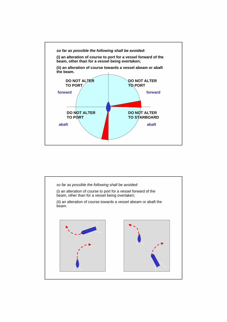
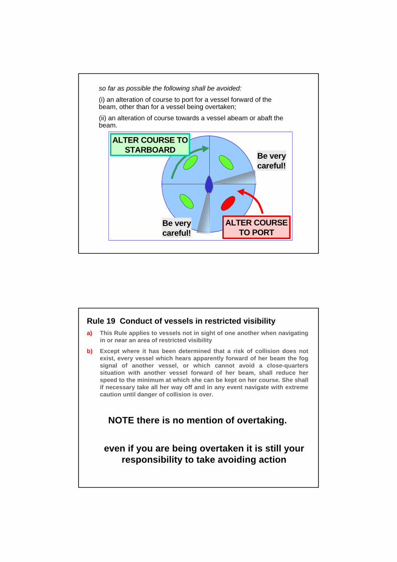
so far as possible the following shall be avoided:(i) an alteration of course to port for a vessel forward of the beam, other than for a vessel being overtaken;(ii) an alteration of course towards a vessel abeam or abaft the beam.
abaftabaft
forwardforward
DO NOT ALTERTO PORT
DO NOT ALTERTO PORT
DO NOT ALTERTO PORT
DO NOT ALTERTO STARBOARD
so far as possible the following shall be avoided:
(i) an alteration of course to port for a vessel forward of the beam, other than for a vessel being overtaken;
(ii) an alteration of course towards a vessel abeam or abaft thebeam.
so far as possible the following shall be avoided:
(i) an alteration of course to port for a vessel forward of the beam, other than for a vessel being overtaken;
(ii) an alteration of course towards a vessel abeam or abaft thebeam.
ALTER COURSE TO PORT
Be verycareful!
Be verycareful!
ALTER COURSE TO STARBOARD
Rule 19 Conduct of vessels in restricted visibilitya) This Rule applies to vessels not in sight of one another when navigating
in or near an area of restricted visibility
b) Except where it has been determined that a risk of collision does not exist, every vessel which hears apparently forward of her beam the fog signal of another vessel, or which cannot avoid a close-quarters situation with another vessel forward of her beam, shall reduce her speed to the minimum at which she can be kept on her course. She shall if necessary take all her way off and in any event navigate with extreme caution until danger of collision is over.
NOTE there is no mention of overtaking.
even if you are being overtaken it is still your responsibility to take avoiding action
Make a RADICAL
Course Change
in order for it
TO BE OBVIOUS
on Radar
© K Bater 2008 90
ARPA - Automatic Radar Plotting AidFor Ships
Calculates and displays Target’s Bearing, Range, True Course and Speed, CPA, TCPA. ARPA is excellent at tracking all visible targets but ONLY if they are visible on about 50 -75% of antenna rotations.It is no use suddenly producing a strong echo only to be missing the next time the antenna goes around.if not carrying a good radar reflector, most yachts cannot be tracked on ARPA. As always ARPA will depend on reliable inputs.
© K Bater 2008 91
(Mini) ARPA – for Yachts
10 targets possible in a listSelect target on screen with cursorTakes a minute to acquire informationDisplays dangerous targets and sounds alarmNeeds fast heading compassDon’t depend on it! Inputs can be in errorNot accurate to 0.5 M
© K Bater 2008 92
MARPA - LimitationsMARPA is historic
it shows what the target WAS doingEchoes must be consistent
Acquiring targets may be difficult for:Weak echoes, and targets close to land, buoys, or to other large targetsRapid manoeuvres by your boat or the targetRough seas with sea clutter may bury the targetPoor heading dataMARPA relies on accurate heading information.
© K Bater 2008 93
ARPA operational warnings for any selected target
Target which closes to a specified range
Target which enters a specified guard zone
Target predicted to close to a specified minimum range and time
A tracked target is lost
© K Bater 2008 94
ARPA Display
1. Present range to the target 2. Present bearing of the target 3. Predicted target range at the
closest point of approach (CPA) 4. Predicted time to CPA (TCPA)5. Calculated true course of target 6. Calculated true speed of target
© K Bater 2008 95
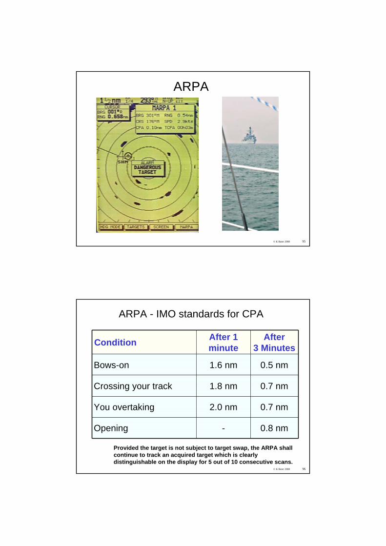
ARPA
© K Bater 2008 96
ARPA - IMO standards for CPA
Condition After 1 minute
After3 Minutes
Bows-on 1.6 nm 0.5 nm
Crossing your track 1.8 nm 0.7 nm
You overtaking 2.0 nm 0.7 nm
Opening - 0.8 nm
Provided the target is not subject to target swap, the ARPA shall continue to track an acquired target which is clearly distinguishable on the display for 5 out of 10 consecutive scans.
© K Bater 2008 97
AIS – Automatic Identification SystemAIS is a system for ships to communicate their positions as partof the global maritime safety system (GMDSS).
Ships over 300 tons carry an AIS system which broadcasts information about the ship
AIS uses bursts of high speed data on two VHF channels in the marine band. 161.975 (Ch 87) and 162.025 (Ch 88) MHz.
Ships broadcast their identity, type, MMSI number, position, course, speed and destination so that other ships can take account of their movements.Other data is draught, length, cargo, no of passengers…
Do not rely on this data for collision avoidance!
Using an AIS receiver and a display, you see a radar-like real-time chart of all the large ships manoeuvring in your area.
Required for VTS systems in ports
Security was a major motivator in USA post 9/11.
http://www.nautinst.org/ais/PDF/AIS_Human_Factors.pdf
© K Bater 2008 98
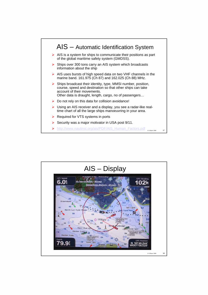
AIS – Display
© K Bater 2008 99
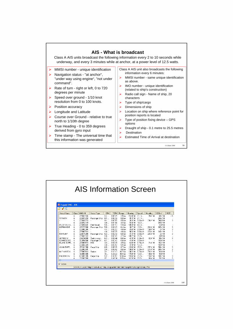
AIS - What is broadcastClass A AIS units broadcast the following information every 2 to 10 seconds while
underway, and every 3 minutes while at anchor, at a power level of 12.5 watts.
MMSI number - unique identificationNavigation status - "at anchor“, "under way using engine“, "not under command".Rate of turn - right or left, 0 to 720 degrees per minuteSpeed over ground - 1/10 knot resolution from 0 to 100 knots.Position accuracyLongitude and Latitude Course over Ground - relative to true north to 1/10th degreeTrue Heading - 0 to 359 degrees derived from gyro inputTime stamp - The universal time that this information was generated
Class A AIS unit also broadcasts the following information every 6 minutes:MMSI number - same unique identification as above.IMO number - unique identification (related to ship's construction)Radio call sign - Name of ship, 20 charactersType of ship/cargoDimensions of shipLocation on ship where reference point for position reports is locatedType of position fixing device – GPS optionsDraught of ship - 0.1 metre to 25.5 metresDestination
Estimated Time of Arrival at destination
© K Bater 2008 100
AIS Information Screen
© K Bater 2008 101
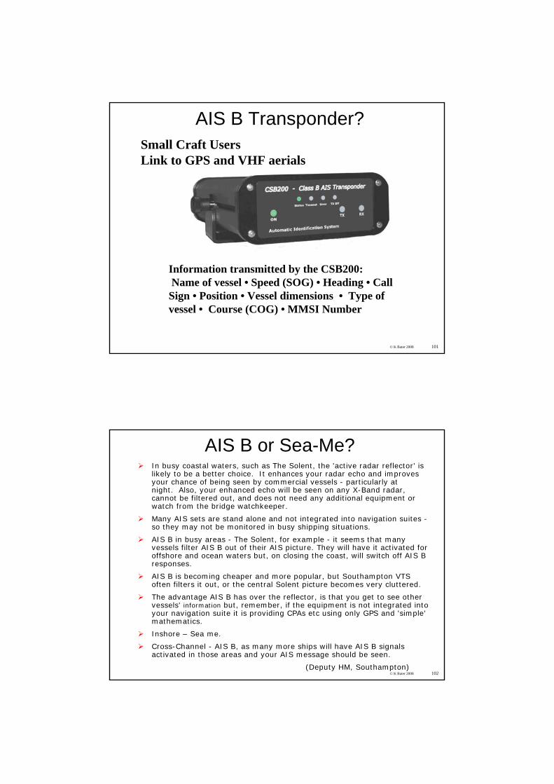
Information transmitted by the CSB200: Name of vessel • Speed (SOG) • Heading • Call Sign • Position • Vessel dimensions • Type of vessel • Course (COG) • MMSI Number
AIS B Transponder?Small Craft UsersLink to GPS and VHF aerials
© K Bater 2008 102
AIS B or Sea-Me?In busy coastal waters, such as The Solent, the 'active radar reflector' is likely to be a better choice. It enhances your radar echo and improves your chance of being seen by commercial vessels - particularly at night. Also, your enhanced echo will be seen on any X-Band radar, cannot be filtered out, and does not need any additional equipment or watch from the bridge watchkeeper.
Many AIS sets are stand alone and not integrated into navigation suites -so they may not be monitored in busy shipping situations.
AIS B in busy areas - The Solent, for example - it seems that many vessels filter AIS B out of their AIS picture. They will have it activated for offshore and ocean waters but, on closing the coast, will switch off AIS B responses.
AIS B is becoming cheaper and more popular, but Southampton VTS often filters it out, or the central Solent picture becomes very cluttered.
The advantage AIS B has over the reflector, is that you get to see other vessels' information but, remember, if the equipment is not integrated into your navigation suite it is providing CPAs etc using only GPS and 'simple' mathematics.
Inshore – Sea me.
Cross-Channel - AIS B, as many more ships will have AIS B signals activated in those areas and your AIS message should be seen.
(Deputy HM, Southampton)
© K Bater 2008 103
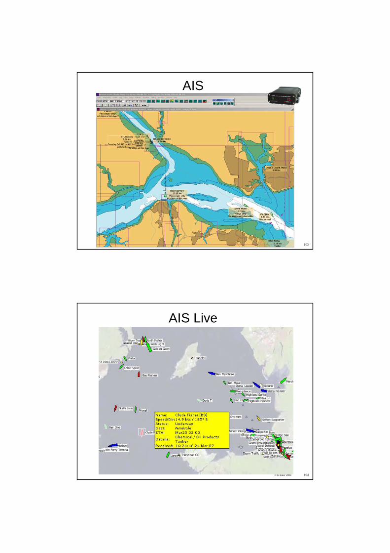
AIS
© K Bater 2008 104
AIS Live
© K Bater 2008 105
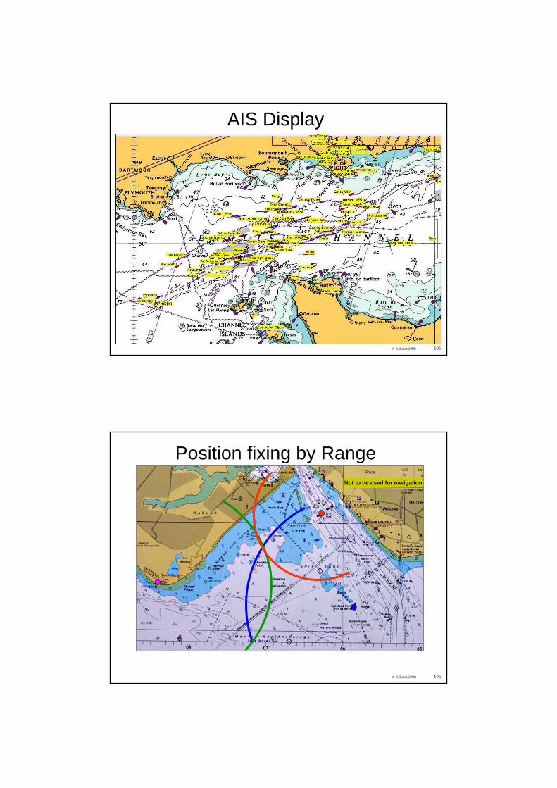
AIS Display
© K Bater 2008 106
Not to be used for navigation
Position fixing by Range
© K Bater 2008 107
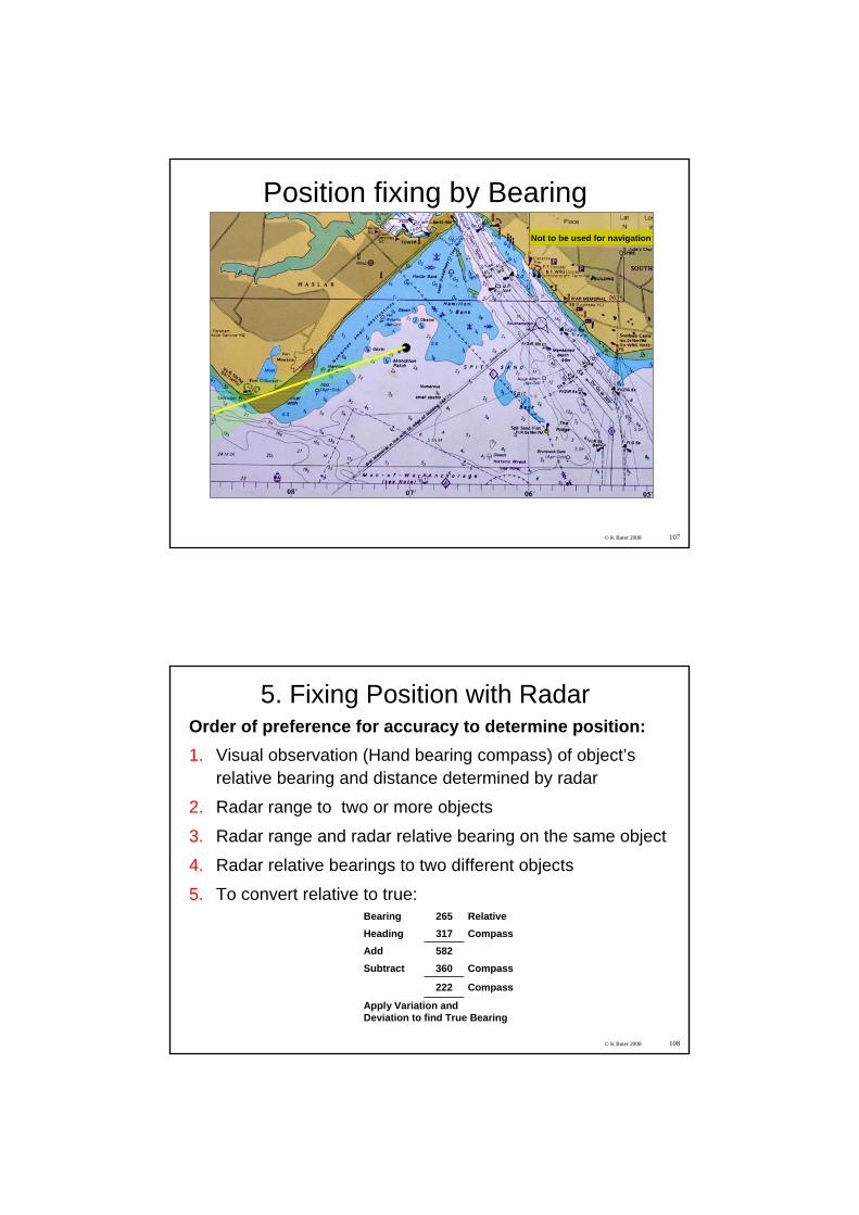
Not to be used for navigation
Position fixing by Bearing
© K Bater 2008 108
5. Fixing Position with RadarOrder of preference for accuracy to determine position:1. Visual observation (Hand bearing compass) of object’s
relative bearing and distance determined by radar
2. Radar range to two or more objects
3. Radar range and radar relative bearing on the same object
4. Radar relative bearings to two different objects
5. To convert relative to true:Bearing 265 RelativeHeading 317 CompassAdd 582Subtract 360 Compass
222 Compass
Apply Variation andDeviation to find True Bearing
© K Bater 2008 109
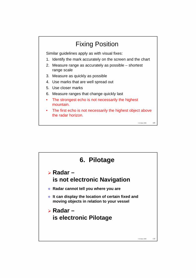
Fixing PositionSimilar guidelines apply as with visual fixes:1. Identify the mark accurately on the screen and the chart2. Measure range as accurately as possible – shortest
range scale3. Measure as quickly as possible4. Use marks that are well spread out5. Use closer marks6. Measure ranges that change quickly last• The strongest echo is not necessarily the highest
mountain.• The first echo is not necessarily the highest object above
the radar horizon.
© K Bater 2008 110
6. Pilotage
Radar –is not electronic NavigationRadar cannot tell you where you are
It can display the location of certain fixed and moving objects in relation to your vessel
Radar –is electronic Pilotage
© K Bater 2008 111
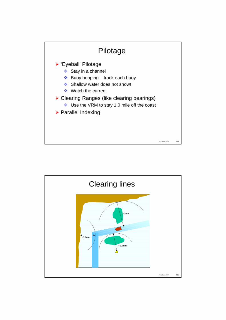
Pilotage
‘Eyeball’ PilotageStay in a channelBuoy hopping – track each buoyShallow water does not show!Watch the current
Clearing Ranges (like clearing bearings)Use the VRM to stay 1.0 mile off the coast
Parallel Indexing
© K Bater 2008 112
> 1nm
> 0.7nm
=0.5nm
Clearing lines
© K Bater 2008 113
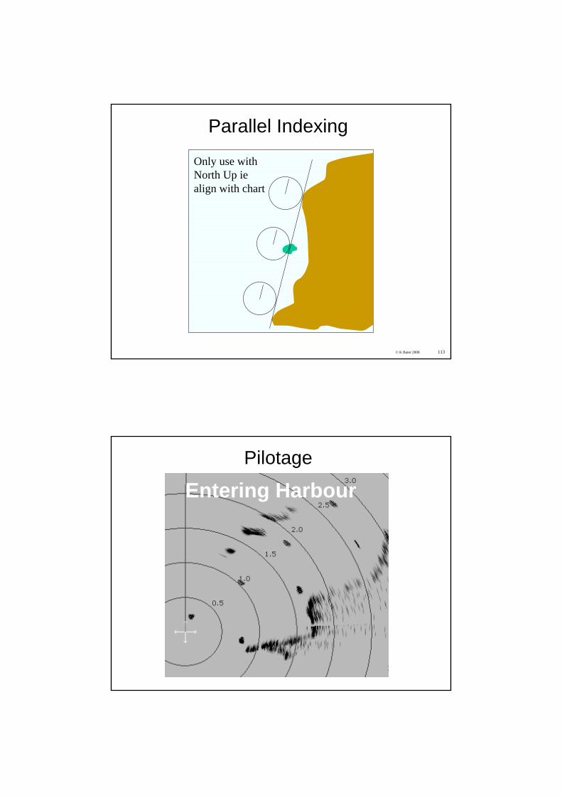
Parallel Indexing
Only use with North Up iealign with chart
Entering HarbourPilotage
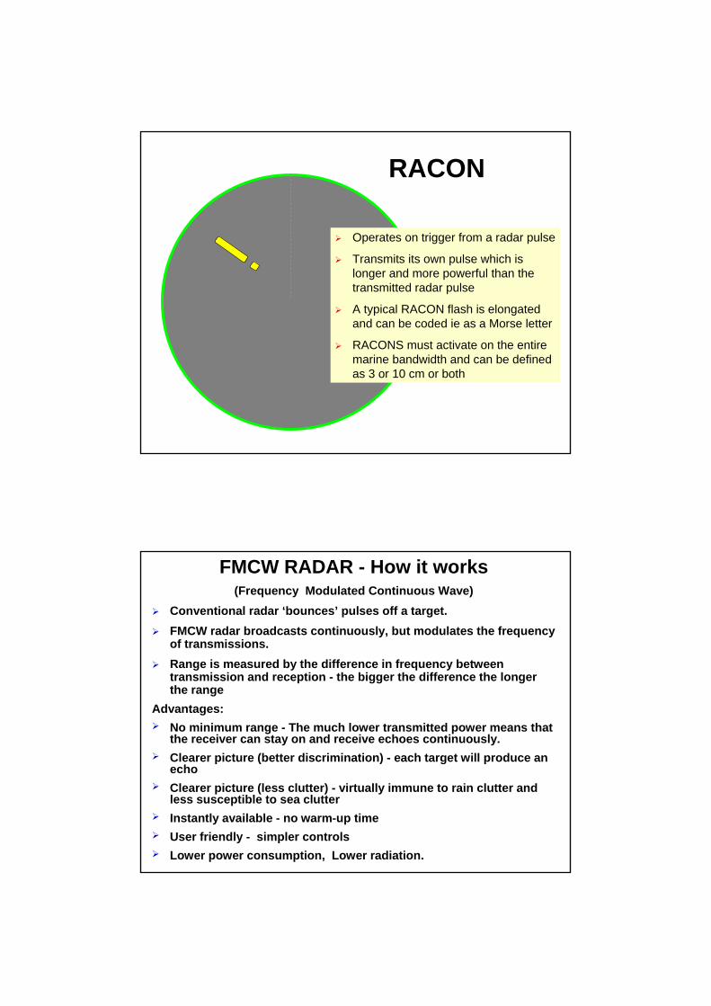
RACON
Operates on trigger from a radar pulse
Transmits its own pulse which is longer and more powerful than the transmitted radar pulse
A typical RACON flash is elongated and can be coded ie as a Morse letter
RACONS must activate on the entire marine bandwidth and can be defined as 3 or 10 cm or both
FMCW RADAR - How it works(Frequency Modulated Continuous Wave)
Conventional radar ‘bounces’ pulses off a target.FMCW radar broadcasts continuously, but modulates the frequency of transmissions.Range is measured by the difference in frequency between transmission and reception - the bigger the difference the longer the range
Advantages:No minimum range - The much lower transmitted power means that the receiver can stay on and receive echoes continuously.Clearer picture (better discrimination) - each target will produce an echoClearer picture (less clutter) - virtually immune to rain clutter and less susceptible to sea clutterInstantly available - no warm-up time User friendly - simpler controlsLower power consumption, Lower radiation.
© K Bater 2008 117
Finale
1610 Uninstall simulator software
Certificates
1615 Wrap up, feedback forms Discussion
1630 ish END
© K Bater 2008 118
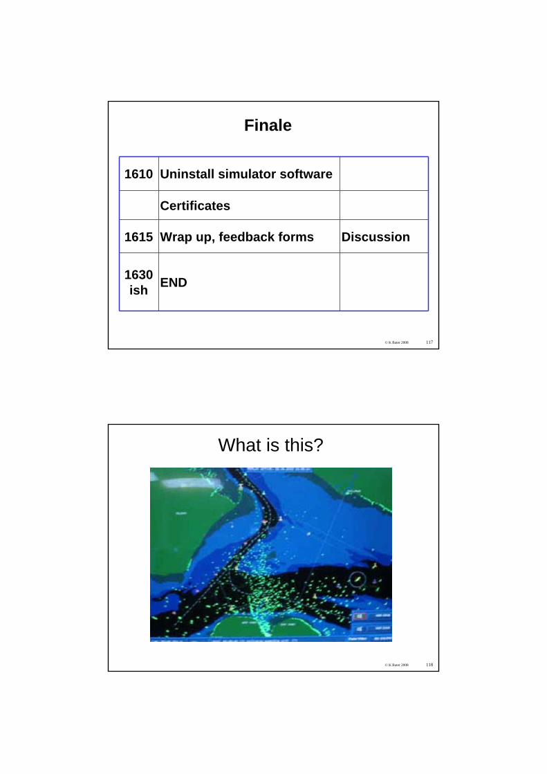
What is this?
© K Bater 2008 119
Books
Adlard Coles Book of Electronic Navigation (Paperback) by Tim Bartlett
Superyacht Masterby Robert Avis


