
Prodigy Series Modular Cuber
Technical Service Manual
also includes CB0522, CB0330, CB0530,CB0630, CB0830 and CB1030
Models C0322, C0522, C0330, C0530, C0630,C0830, C1030, C1448, C1848 and C2148

Introduction
This technical manual covers the Prodigy line, excluding the Eclipse remote low side models.All models except Eclipse are shipped with an Installation and User's manual, which can bereferred to separately. General installation information is included in this manual.
May 2011 Page 1
Table of Contents
Model Number Description . . . . . . . . . page 2
Water . . . . . . . . . . . . . . . . . . . . page 3
General Installation - Air or Water Cooled . page 4
Water purge setting . . . . . . . . . . . . page 8
General Installation - Remote . . . . . . . page 9
Pre-Charged Tubing Coupling Connections page 17
Adjustments . . . . . . . . . . . . . . . . page 20
Prodigy Cuber System Information. . . . . page 21
Controller Information . . . . . . . . . . . page 22
How It Works - Air Cooled . . . . . . . . . page 24
How It Works - Water Cooled . . . . . . . page 25
How It Works - Remote. . . . . . . . . . . page 26
Electrical Sequence - Air or Water Cooled. page 27
Electrical Sequence - Remote Cooled . . . page 29
Remote Schematics . . . . . . . . . . . . page 31
Electrical Component Details . . . . . . . page 32
Refrigeration . . . . . . . . . . . . . . . . page 35
Water System . . . . . . . . . . . . . . . page 36
Control Operation . . . . . . . . . . . . . page 37
Control Safeties . . . . . . . . . . . . . . page 38
Restarts. . . . . . . . . . . . . . . . . . . page 39
Control Button Use (from standby) . . . . . page 40
Control Button Use - continued . . . . . . page 41
Diagnostics – Air Cooled . . . . . . . . . . page 42
Low Ice Making Capacity - Air Cooled . . . page 45
Makes Excessive Noise - Air Cooled. . . . page 46
Diagnostics - Water Cooled . . . . . . . . page 47
Low ice Making Capacity - Water Cooled . page 50
Makes Excessive Noise - Water Cooled . . page 51
Diagnostics - Remote Air Cooled . . . . . page 52
Low Ice Making Capacity - Remote . . . . page 55
Makes Excessive Noise - Remote . . . . . page 56
Test Procedures - Sensors. . . . . . . . . page 57
Ice Thickness Sensor . . . . . . . . . . . page 58
Water Level Sensor . . . . . . . . . . . . page 59
Temperature Sensors . . . . . . . . . . . page 60
Test Procedures - Loads . . . . . . . . . . page 61
Compressor Electrical Chart . . . . . . . . page 62
Refrigerant Charges . . . . . . . . . . . . page 63
Test Procedures - Loads . . . . . . . . . . page 64
Technical Information . . . . . . . . . . . page 72
Heat Load & Condenser Water GPM . . . page 73
Controller Differences . . . . . . . . . . . page 74
Thermistor Values . . . . . . . . . . . . . page 75
Performance Data . . . . . . . . . . . . . page 76
Performance Data - Remotes . . . . . . . page 86
Wiring Diagrams . . . . . . . . . . . . . . page 94
Repair Procedures . . . . . . . . . . . . . page 107
Refrigeration Removal and Replacement Procedures. . . . . . . . . . . . . . . . . . . . . . . page 115
Optional add-on control information . . . . page 120

Model Number Description
Example:
• C0530SA-1C
• C= cuber. CB = Prodigy Advanced Sustainability Cuber
• 05= nominal ice capacity in 100s of pounds
• 30= nominal width of cabinet. Other sizes are 22 and 48.
• S= Cube size. S=small or half dice cube. M=medium or full dice cube
• A=Condenser type. A=air cooled. W=water cooled. R = Remote
• -1=Electrical code. -1=115 volts. -32=208-230 single phase. -3=208-230 three phase.-6=230 50 Hz
• C=Series revision code. C=third series
Note: In some areas of this manual model numbers may include only the first five characters ofthe model number, meaning that the cube size, condenser type and voltage differences are notcritical to the information listed there.
Scotsman reserves the right to make design changes and/or improvements at any time.Specifications and design are subject to change without notice.
September 2011 Page 2
Water
The quality of the water supplied to the ice machine will have an impact on the time betweencleanings and ultimately on the life of the product. There are two ways water can containimpurities: in suspension or in solution. Suspended solids can be filtered out. In solution ordissolved solids cannot be filtered, they must be diluted or treated. Water filters arerecommended to remove suspended solids. Some filters have treatment in them forsuspended solids. Check with a water treatment service for a recommendation.
RO water. This machine can be supplied with Reverse Osmosis water, but the waterconductivity must be no less than 10 microSiemens/cm.
Potential for Airborne Contamination
Installing an ice machine near a source of yeast or similar material can result in the need formore frequent sanitation cleanings due to the tendency of these materials to contaminate themachine. Most water filters remove chlorine from the water supply to the machine whichcontributes to this situation. Testing has shown that using a filter that does not removechlorine, such as the Scotsman Aqua Patrol, will greatly improve this situation, while the icemaking process itself will remove the chlorine from the ice, resulting in no taste or odor impact.Additionally, devices intended to enhance ice machine sanitation, such as the Scotsman AquaBullet, can be placed in the machine to keep it cleaner between manual cleanings.
Water Purge
Cube ice machines use more water than what ends up in the bin as ice. While most water isused during ice making, a portion is designed to be drained out every cycle to reduce theamount of hard water scale in the machine. That’s known as water purge, and an effectivepurge can increase the time between needed water system cleaning.
In addition, this product has the capability to automatically vary the amount of water purgeedbased on the purity of the water supplied to it. The water purge rate can also be set manually.Adjustments of purge due to local water conditions are not covered by warranty.
September 2006 Page 3

General Installation - Air or Water Cooled
Location Limitations:
The product is designed to be installed indoors, in a controlled environment. Air cooled modelsdischarge very warm air into the room out the back. Space must be allowed at the left side andback for air intake and discharge. Water cooled models discharge warm water into thebuilding’s drain. Space needs to be provided on both sides and above for service access.
Space Limitations
Note: Although the machine will function, ice capacity of air cooled machines will be significantly reducedwith minimal clearance at the sides, back and top. Some space is recommended for service andmaintenance purposes on all models.
6" of space at the sides and back are required for adequate operation. To get the mostcapacity, locate the machine away from heat producing appliances and heating ducts.
22 and 30 inch wide models: Airflow is in the left side, out the back (as viewed from the front).
48 inch wide models: Air flow is in the front and left side and out the back.
Environmental Limitations
Minimum Maximum
Air temperature 50oF. 100
oF.
Water temperature 40oF. 100
oF.
Water pressure 20 psi 80 psi
Power supply – acceptable voltage ranges
Minimum Maximum
115 volt model 104 volts 126 volts
208-230 volt model 198 volts 253 volts
Warranty Information
The warranty statement for this product is provided separately from this manual. Refer to it forapplicable coverage. In general warranty covers defects in material or workmanship. It doesnot cover maintenance, corrections to installations, or situations when the machine is operatedin circumstances that exceed the limitations printed above.
September 2006 Page 4

Plumbing Requirements
All models require connection to cold, potable water. A hand actuated valve within site of themachine is required. Air cooled models have a single 3/8” FPT inlet water connection; a 3/8”FPT to 3/8” male flare adapter is supplied with the machine and can be used if desired.
Water cooled models have the same inlet fitting plus an additional 3/8” FPT condenser inletwater connection.
Water Filters
If connecting to water filtration, filter only the water to the reservoir, not to the condenser.Install a new cartridge if the filters were used with a prior machine.
All models require drain tubing to be attached to them. Air cooled models have a single ¾”FPT drain fitting in the back of the cabinet. Water cooled models have the same fitting plus anadditional ½” FPT drain fitting in the back of the cabinet.
Install new tubing when replacing a prior ice machine, as the tubing will have been sized forthe old model and might not be correct for this one.
Note: This NSF listed model has a 1" anti-back flow air gap between the water inlet tube end and thehighest possible reservoir water level, no back flow device is required for the potable water inlet.
Drain Tubing:
Use rigid drain tubes and route them separately – do not Tee into the bin’s drain and, if water
cooled, do not Tee the condenser drain into the reservoir or bin drain.
Vent the reservoir drain. A vertical vent at the back of the drain, extended about 8 – 10” willallow the gravity drain to empty and also keep any surges during draining from dischargingwater out the vent..
Horizontal runs of drain tubing need a ¼” fall per foot of run for proper draining.
Follow all applicable codes.
September 2006 Page 5
General Installation - Air or Water Cooled

Electrical
See the spec sheet or User's Manual for Minimum Circuit Ampacity or Maximum Fuse Sizeratings.
The machine is not supplied with a power cord, one must either be field installed or themachine hard-wired.
The dataplate on the back of the cabinet details the power requirements, including voltage,phase, minimum circuit ampacity and maximum fuse size. HACR type circuit breakers may beused in place of fuses. Extension cords are not permitted. Use of a licensed electrician isrecommended.
Electrical connections are made inside the junction box in the back panel of the ice machine.
Follow all applicable local, state and national codes.
September 2006 Page 6
General Installation - Air or Water Cooled

Adjustments
Ice Bridge Thickness
Caution: Do not make the bridge too thin or themachine will not harvest properly. Bridge thicknessadjustments are not covered by warranty.
Shut machine off.
Access the ice thickness sensor.
Check gap between metal tip and evaporatorgrid. Small cube standard gap is 3/16 inch,medium cube standard gap is 7/32 inch. Toset, place a 3/16" (small cube) or 7/32"(medium cube) drill bit between sensor tipand evaporator to check. Adjust gap usingadjustment screw.
Restart unit and check ice bridge. Repeat asneeded.
September 2006 Page 7
General Installation - Air or Water Cooled
Ice Thickness Sensor Adjustment
Gap
AdjustmentScrew
Side View of Evaporator and Ice ThicknessSensor
Ice Thickness SensorEvaporator
Gap
Ice Bridge Thickness Measurement
1/8-3/16"
bridge
Note: Indentations may be deeper on C0322 and C0330
1/8" indentation
Too Big Too SmallJust Right

Water purge setting
The water purge is factory set to the Automatic setting. The setting can be changed to one of 5manual settings or placed on automatic. The purge setting shows in the Code Display.
purgesetting
1 -Minimum
2 -Moderate
3 -Standard
4 -Heavy
5 -Maximum
A - Automatic
WaterType
RO waterorequivalent,TDS lessthan 35
Low TDSnon - ROwater
Settingfor typicalwater
HighTDSwater
Very highTDS water,greater than256
Any withconductivitynot less than10microSiemens/cm
To set:
Switch the machine OFF by holding the Off button in until a number or the letter A shows onthe display.
Press and release the On button repeatedly until the number on the display corresponds to thedesired setting.
Press and release the Off switch again to return to the normal control state.
September 2006 Page 8

General Installation - Remote
Location Limitations
This ice system is made up of three parts, the ice making machine, or head; the remotecondenser; and the interconnecting tubing. The ice making machine must be installed indoors,in a controlled environment. Space must be provided near the machine for service access. Theremote condenser may be installed above or below the ice machine, per the limits stated laterin this manual. The remote condenser may be installed outdoors within the temperature limitslisted below. The interconnecting tubing must be installed per the directions stated in thismanual, and the amount of tubing exposed to uncontrolled temperatures must be minimized.
Space Limitations
Although the machine will function with no clearance to the top and sides, some space must beallowed for service access. Building the machine in with no access will cause higher servicecost, in many cases this extra cost may not be covered by warranty.
Environmental Limitations, ice machine:
Minimum Maximum
Air temperature 50oF. 100
oF.
Water temperature 40oF. 100
oF.
Water Pressure 20 psi 80 psi
Environmental Limitations, remote condenser
Minimum Maximum
Air temperature -20oF. 120
oF.
Power Supply
Minimum Maximum
115 volt model 104 volts 126 volts
208-230 volt model 198 volts 253 volts
Warranty Information
The warranty statement for this product is provided separately from this manual. Refer to it forapplicable coverage. In general warranty covers defects in material and workmanship. It doesnot cover maintenance, corrections to installations, or situations when the ice machine isoperated in circumstances that exceed the limitations printed above.
September 2006 Page 9
Product Description and Electrical Requirements
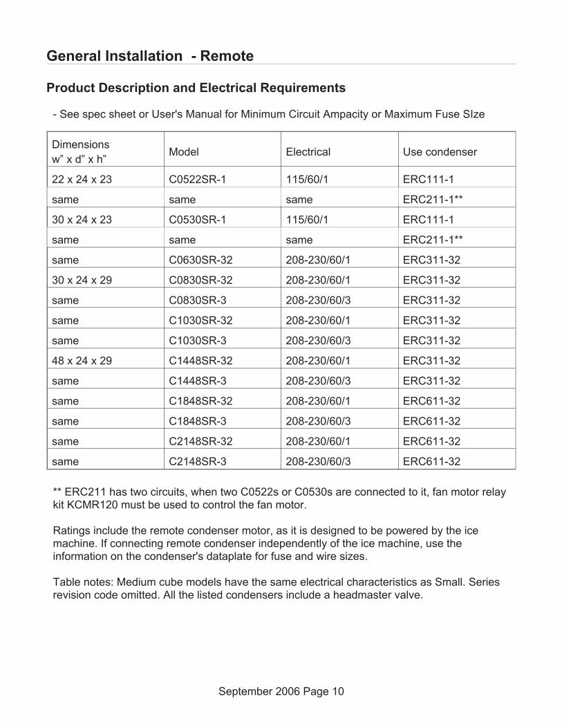
- See spec sheet or User's Manual for Minimum Circuit Ampacity or Maximum Fuse SIze
Dimensions
w” x d” x h”Model Electrical Use condenser
22 x 24 x 23 C0522SR-1 115/60/1 ERC111-1
same same same ERC211-1**
30 x 24 x 23 C0530SR-1 115/60/1 ERC111-1
same same same ERC211-1**
same C0630SR-32 208-230/60/1 ERC311-32
30 x 24 x 29 C0830SR-32 208-230/60/1 ERC311-32
same C0830SR-3 208-230/60/3 ERC311-32
same C1030SR-32 208-230/60/1 ERC311-32
same C1030SR-3 208-230/60/3 ERC311-32
48 x 24 x 29 C1448SR-32 208-230/60/1 ERC311-32
same C1448SR-3 208-230/60/3 ERC311-32
same C1848SR-32 208-230/60/1 ERC611-32
same C1848SR-3 208-230/60/3 ERC611-32
same C2148SR-32 208-230/60/1 ERC611-32
same C2148SR-3 208-230/60/3 ERC611-32
** ERC211 has two circuits, when two C0522s or C0530s are connected to it, fan motor relaykit KCMR120 must be used to control the fan motor.
Ratings include the remote condenser motor, as it is designed to be powered by the icemachine. If connecting remote condenser independently of the ice machine, use theinformation on the condenser's dataplate for fuse and wire sizes.
Table notes: Medium cube models have the same electrical characteristics as Small. Seriesrevision code omitted. All the listed condensers include a headmaster valve.
September 2006 Page 10
General Installation - Remote

Central Condenser Coils
The ice machine may be connected to a central condenser coil. The requirements are:
• Coil – not previously used with mineral oil system. Virgin coil preferred.
• Correct size (internal volume) and capacity (BTUH).
• Includes a headmaster valve for discharge pressure control. Headmaster kit available forcertain MAC condensers, kit number is RCKCME6GX.
• Fan motor on all the time or controlled to be on whenever the ice machine is operating.
• Non-Scotsman condensers must have prior Scotsman Engineering approval for warrantycoverage to be in effect.
Precharged tubing kits:
The ice making head’s and the remote condenser’s refrigeration circuits must be connected.They are designed to be connected using precharged refrigerant tubing, supplied in kits ofliquid and discharge tubes. Several lengths are available, order the one that just exceeds thelength needed for the site.
10” 25’ 40’ 75’
RTE10 RTE25 RTE40 RTE75
No additional refrigerant is required. Note: Refrigerant charge is supplied with the ice machine.
January 2009 Page 11
General Installation - Remote

Water
The quality of the water supplied to the ice machine will have an impact on the time betweencleanings and ultimately on the life of the product. There are two ways water can containimpurities: in suspension or in solution. Suspended solids can be filtered out. In solution ordissolved solids cannot be filtered, they must be diluted or treated. Water filters arerecommended to remove suspended solids. Some filters have treatment in them forsuspended solids. Check with a water treatment service for a recommendation.
RO water. This machine can be supplied with Reverse Osmosis water, but the water
conductivity must be no less than 10 microSiemens/cm.
Potential for Airborne Contamination
Installing an ice machine near a source of yeast or similar material can result in the need formore frequent sanitation cleanings due to the tendency of these materials to contaminate themachine. Most water filters remove chlorine from the water supply to the machine whichcontributes to this situation. Testing has shown that using a filter that does not removechlorine, such as the Scotsman Aqua Patrol, will greatly improve this situation, while the icemaking process itself will remove the chlorine from the ice, resulting in no taste or odor impact.Additionally, devices intended to enhance ice machine sanitation, such as the Scotsman AquaBullet, can be placed in the machine to keep it cleaner between manual cleanings.
Water purge
Cube ice machines use more water than what ends up in the bin as ice. While most water isused during ice making, a portion is designed to be drained out every cycle to reduce theamount of hard water scale in the machine. That’s known as water purge, and an effectivepurge can increase the time between needed water system cleaning.
In addition, this product is designed to automatically vary the amount of water purged based onthe purity of the water supplied to it. The water purge rate can also be set manually.Adjustments of purge due to local water conditions are not covered by warranty.
September 2006 Page 12
General Installation - Remote

Remote Condenser Location
Use the following for planning the placement of the condenser relative to the ice machine - seeillustration on the following page.
Location Limits - condenser location must not exceed ANY of the following limits:
• Maximum rise from the ice machine to the condenser is 35 physical feet
• Maximum drop from the ice machine to the condenser is 15 physical feet
• Physical line set maximum length is 100 feet.
• Calculated line set length maximum is 150.
Calculation Formula:
• Drop = dd x 6.6 (dd = distance in feet)
• Rise = rd x 1.7 (rd = distance in feet)
• Horizontal Run = hd x 1 (hd = distance in feet)
• Calculation: Drop(s) + Rise(s) + Horizontal Run = dd+rd+hd = Calculated Line Length
Configurations that do NOT meet these requirements must receive prior written
authorization from Scotsman.
Do NOT:
• Route a line set that rises, then falls, then rises.
• Route a line set that falls, then rises, then falls.
Calculation Example 1:
The condenser is to be located 5 feet below the ice machine and then 20 feet awayhorizontally.
5 feet x 6.6 = 33. 33 + 20 = 53. This location would be acceptable
Calculation Example 2:
The condenser is to be located 35 feet above and then 100 feet away horizontally. 35 x 1.7 =59.5. 59.5 +100 = 159.5. 159.5 is greater than the 150 maximum and is NOT acceptable.
Operating a machine with an unacceptable configuration is misuse and will void the
warranty.
September 2006 Page 13
General Installation - Remote

For The Installer: Remote Condenser
Locate the condenser as near as possible to the interior location of the ice machine.
Note: The location of the condenser is relative to the ice machine is LIMITED by the specification on theprior page.
Meet all applicable building codes.
Roof Attachment
Install and attach the remote condenser to the roof of the building, using the methods andpractices of construction that conform to the local building codes, including having a roofingcontractor secure the condenser to the roof.
September 2006 Page 14
General Installation - Remote
22
.87
"1
7.1
5"
40.35"hd
rd
dd
Remote
Condenser
Locate ABOVE
Remote
Condenser
Locate BELOW
CondenserDistance &LocationMax
35'
Max15'

Precharged Line Routing
Do not connect the precharged tubing until all routing and forming of the tubing is complete.See the Coupling Instructions for final connections.
1. Each set of pre-charged tubing lines contains a 3/8” diameter liquid line, and a 1/2” diameterdischarge line. Both ends of each line have quick connect couplings, the end without accessvalves goes to the ice maker.
Note: The openings in the building ceiling or wall, listed in the next step, are the minimum sizesrecommended for passing the refrigerant lines through.
2. Have the roofing contractor cut a minimum hole for the refrigerant lines of 1 3/4”. Checklocal codes, a separate hole may be required for the electrical power supply to the condenser.
Caution: Do NOT kink the refrigerant tubing while routing it.
3. Route the refrigerant tubes thru the roof opening. Follow straight line routing wheneverpossible. Excess tubing may EITHER be coiled up INSIDE the building OR cut out prior toconnection to the ice maker and condenser.
If the excess tubing is cut out, after re-brazing the tubing must be evacuated prior toconnection to the ice maker or condenser.
Note brazing requires a nitrogen purge.
If the excess tubing is to be coiled, spiral it horizontally to avoid excess trapping in the lines.
5. Have the roofing contractor seal the holes in the roof per local codes
September 2006 Page 15
General Installation - Remote

Coupling Instructions
The couplings on the ends of the pre-charged line sets are self-sealing when installed properly.Follow these instructions carefully.
These steps must be performed by an EPA Certified Type II or higher technician.
Initial Connections
1. Remove the protector caps and plugs. Wipe the seats and threaded surfaces with a cleancloth to remove any possible foreign matter.
2. Lubricate the inside of the couplings, especially the O-rings, with refrigerant oil.
3. Position the fittings on the correct connections on the condenser and ice machine.
• The 1/2" discharge line (schrader valve end) goes to the remote condenser fitting marked“discharge line”.
• The 3/8" liquid line (schrader valve end) goes to the remote condenser fitting marked“liquid line”.
• The 1/2" discharge line goes to the ice maker fitting marked “discharge line”.
• The 3/8" liquid line goes to the ice maker fitting marked “liquid line”.
Final Connections:
4a. Begin by tightening the couplings together by hand until it is certain that the threads areproperly engaged.
4b. Then using two wrenches tighten the coupling until it bottoms out or a definite increase inresistance is felt.
It is important that ONLY the nut on the pre-charged tube be turned, or the diaphragms will betorn out by the piercing knives and they will be loose in the refrigeration system. Note: As thecouplings are tightened, the diaphragms in the quick connect couplings will begin to bepierced. As that happens, there will be some resistance to tightening the swivel nut.
4c. Continue tightening the swivel nut until it bottoms out or a very definite increase inresistance is felt (no threads should be showing).
5. Use a marker or pen to mark a line on the coupling nut and unit panel. Then tighten thecoupling nut an additional one-quarter turn. The line will show the amount that the nut turns.Do NOT over tighten.
6. After all connections have been made, and after the receiver valve has been opened (openat Initial Start Up), check the couplings for leaks.
September 2006 Page 16
General Installation - Remote
Pre-Charged Tubing Coupling Connections
September 2006 Page 17
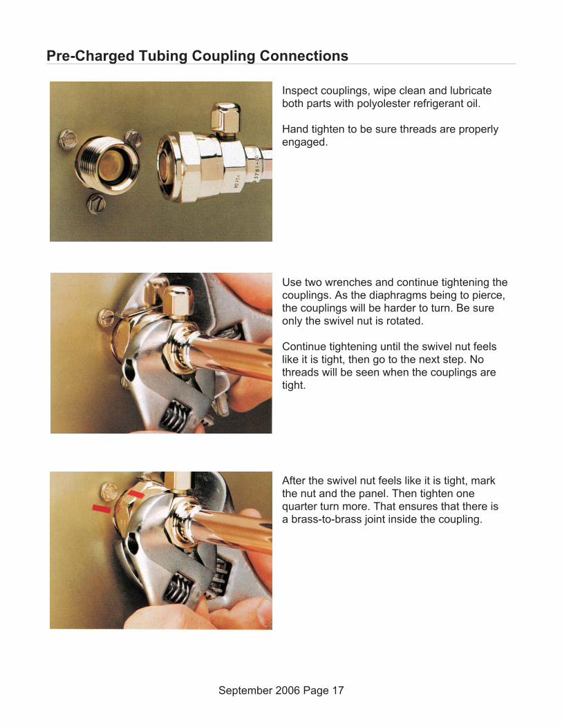
Inspect couplings, wipe clean and lubricateboth parts with polyolester refrigerant oil.
Hand tighten to be sure threads are properlyengaged.
Use two wrenches and continue tightening thecouplings. As the diaphragms being to pierce,the couplings will be harder to turn. Be sureonly the swivel nut is rotated.
Continue tightening until the swivel nut feelslike it is tight, then go to the next step. Nothreads will be seen when the couplings aretight.
After the swivel nut feels like it is tight, markthe nut and the panel. Then tighten onequarter turn more. That ensures that there isa brass-to-brass joint inside the coupling.
Plumbing Requirements
All models require connection to cold, potable water. A hand actuated valve within site of themachine is required. There is a single 3/8” FPT inlet water connection, a 3/8” FPT to 3/8” maleflare adapter is supplied with the machine and can be used if desired.
Water Filters
Install a new cartridge if the filters were used with a prior machine.
All models require drain tubing to be attached to them. There is a single ¾” FPT drain fitting inthe back of the cabinet.
Install new tubing when replacing a prior ice machine, as the tubing will have been sized forthe old model and might not be correct for this one.
Connect water supply to water inlet fitting.
Note: This NSF listed model has a 1" anti-back flow air gap between the potable water inlet tube end andthe highest possible reservoir water level, no back flow device is required.
Connect drain tubing to drain fitting.
Route the drain tubing to building drain. Follow local codes for drain air gap.
Use rigid drain tubes and route them separately – do not Tee into the bin’s drain.
Vent the reservoir drain. A vertical vent at the back of the drain, extended about 8 – 10” willallow the gravity drain to empty and also keep any surges during draining from dischargingwater.
Horizontal runs of drain tubing need a ¼” per fall per foot of run for proper draining.
Follow all applicable codes.
September 2006 Page 18
General Installation - Remote

Electrical
The machine is not supplied with a power cord, one must either be field installed or themachine hard-wired.
The dataplate on the back of the cabinet details the power requirements, including voltage,phase, minimum circuit ampacity and maximum fuse size. HACR type circuit breakers may beused in place of fuses. Extension cords are not permitted. Use of a licensed electrician isrecommended.
The ice maker is designed to operate on its own electrical circuit and must be individuallyfused. Voltage variation must not exceed the limits listed earlier.
The remote condenser is designed to be powered from the ice machine. A separate knockouthole has been provided in the ice maker electrical junction box.
Electrical connections are made inside the junction box in the back panel of the ice machine.
Remove the junction box cover and route the power cord through the access hole and properlyattach the power supply wires to the leads in the junction box.
Attach the remote condenser fan motor wires to the wires in the junction box tagged “fan motorleads”.
Install field supplied strain reliefs per code. Attach a ground wire to the ground connection inthe junction box.
Check voltage when complete.
Return the junction box cover to its original position and secure with the original screws.
Follow all applicable local, state and national codes.
September 2006 Page 19
General Installation - Remote
Adjustments
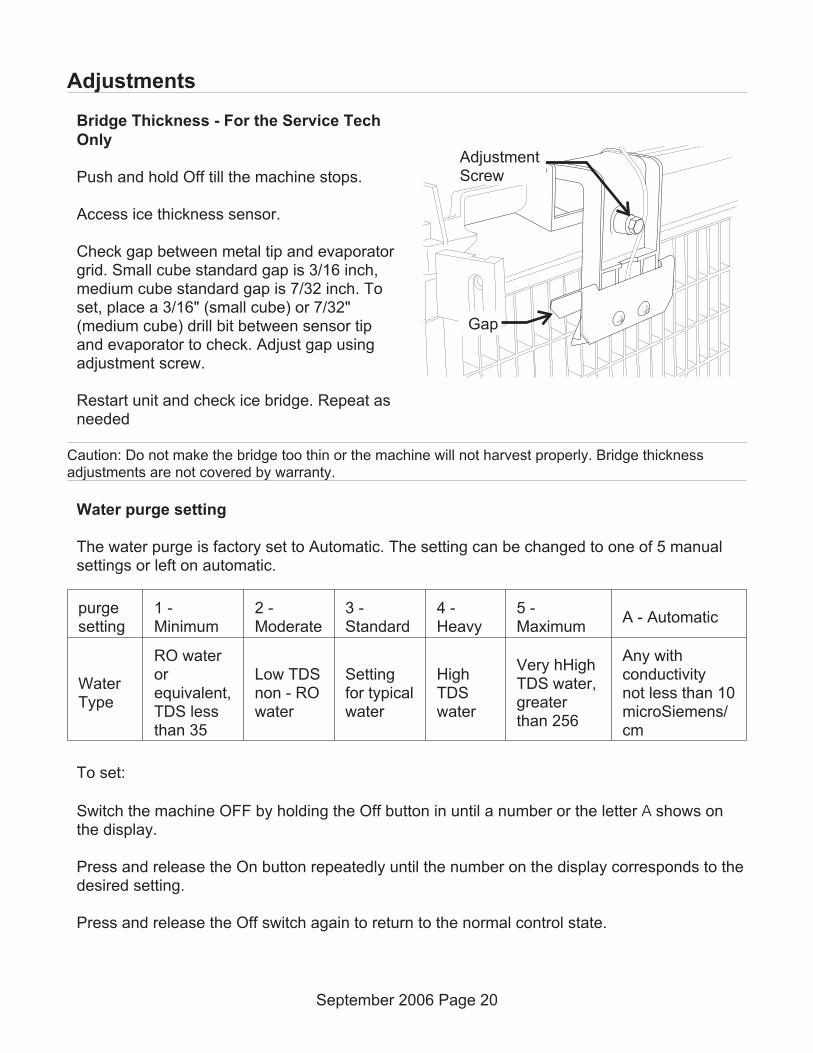
Bridge Thickness - For the Service Tech
Only
Push and hold Off till the machine stops.
Access ice thickness sensor.
Check gap between metal tip and evaporatorgrid. Small cube standard gap is 3/16 inch,medium cube standard gap is 7/32 inch. Toset, place a 3/16" (small cube) or 7/32"(medium cube) drill bit between sensor tipand evaporator to check. Adjust gap usingadjustment screw.
Restart unit and check ice bridge. Repeat asneeded
Caution: Do not make the bridge too thin or the machine will not harvest properly. Bridge thicknessadjustments are not covered by warranty.
Water purge setting
The water purge is factory set to Automatic. The setting can be changed to one of 5 manualsettings or left on automatic.
purgesetting
1 -Minimum
2 -Moderate
3 -Standard
4 -Heavy
5 -Maximum
A - Automatic
WaterType
RO waterorequivalent,TDS lessthan 35
Low TDSnon - ROwater
Settingfor typicalwater
HighTDSwater
Very hHighTDS water,greaterthan 256
Any withconductivitynot less than 10microSiemens/cm
To set:
Switch the machine OFF by holding the Off button in until a number or the letter A shows onthe display.
Press and release the On button repeatedly until the number on the display corresponds to thedesired setting.
Press and release the Off switch again to return to the normal control state.
September 2006 Page 20
Gap
AdjustmentScrew

Prodigy Cuber System Information
Overall System Type:• Refrigeration: Mechanical, either air cooled, water cooled or remote cooled.
• Water System: Inlet water solenoid valve fills reservoir once per cycle. Purge solenoidvalve opens to discharge some reservoir water once per cycle.
• Control System: Electronic
• Harvest cycle sensor: Conductivity probe
• Water full/empty sensor: Conductivity probe
• Bin Control: Curtain Switch
• Ice type: Unified
• Harvest system: Hot gas defrost with mechanical assist
Electrical Components:• Compressor
• Contactor
• Water Pump
• Inlet Water Solenoid Valve
• Purge or purge Valve
• Fan Motor(s)
• Fan motor pressure control
• High pressure cut out – certain AC models only
• Harvest Assist Solenoid(s)
• Hot Gas Valve(s)
• Controller
• Transformer – 12v AC for the controller only
• Water Level Sensor
• Ice Thickness Sensor
• Curtain Switch(es)
September 2006 Page 21
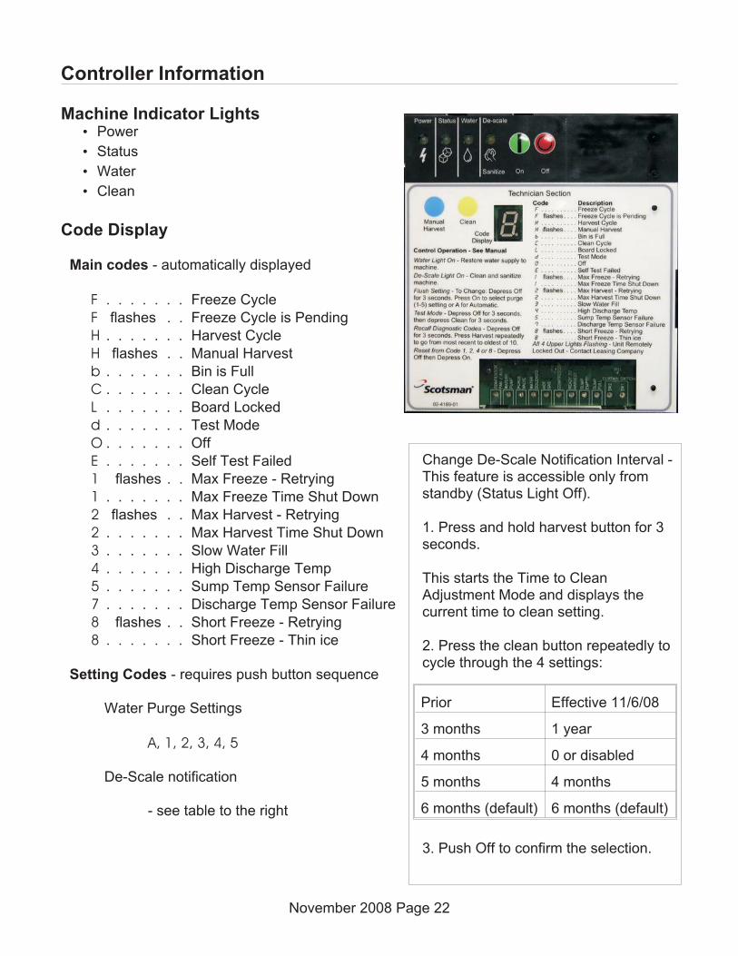
Controller Information
Machine Indicator Lights• Power
• Status
• Water
• Clean
Code Display
Main codes - automatically displayed
F . . . . . . . Freeze Cycle
F flashes . . Freeze Cycle is Pending
H . . . . . . . Harvest Cycle
H flashes . . Manual Harvest
b . . . . . . . Bin is Full
C . . . . . . . Clean Cycle
L . . . . . . . Board Locked
d . . . . . . . Test Mode
O . . . . . . . Off
E . . . . . . . Self Test Failed
1 flashes . . Max Freeze - Retrying
1 . . . . . . . Max Freeze Time Shut Down
2 flashes . . Max Harvest - Retrying
2 . . . . . . . Max Harvest Time Shut Down
3 . . . . . . . Slow Water Fill
4 . . . . . . . High Discharge Temp
5 . . . . . . . Sump Temp Sensor Failure
7 . . . . . . . Discharge Temp Sensor Failure
8 flashes . . Short Freeze - Retrying
8 . . . . . . . Short Freeze - Thin ice
Setting Codes - requires push button sequence
Water Purge Settings
A, 1, 2, 3, 4, 5
De-Scale notification
- see table to the right
November 2008 Page 22
Change De-Scale Notification Interval -This feature is accessible only fromstandby (Status Light Off).
1. Press and hold harvest button for 3seconds.
This starts the Time to CleanAdjustment Mode and displays thecurrent time to clean setting.
2. Press the clean button repeatedly tocycle through the 4 settings:
Prior Effective 11/6/08
3 months 1 year
4 months 0 or disabled
5 months 4 months
6 months (default) 6 months (default)
3. Push Off to confirm the selection.
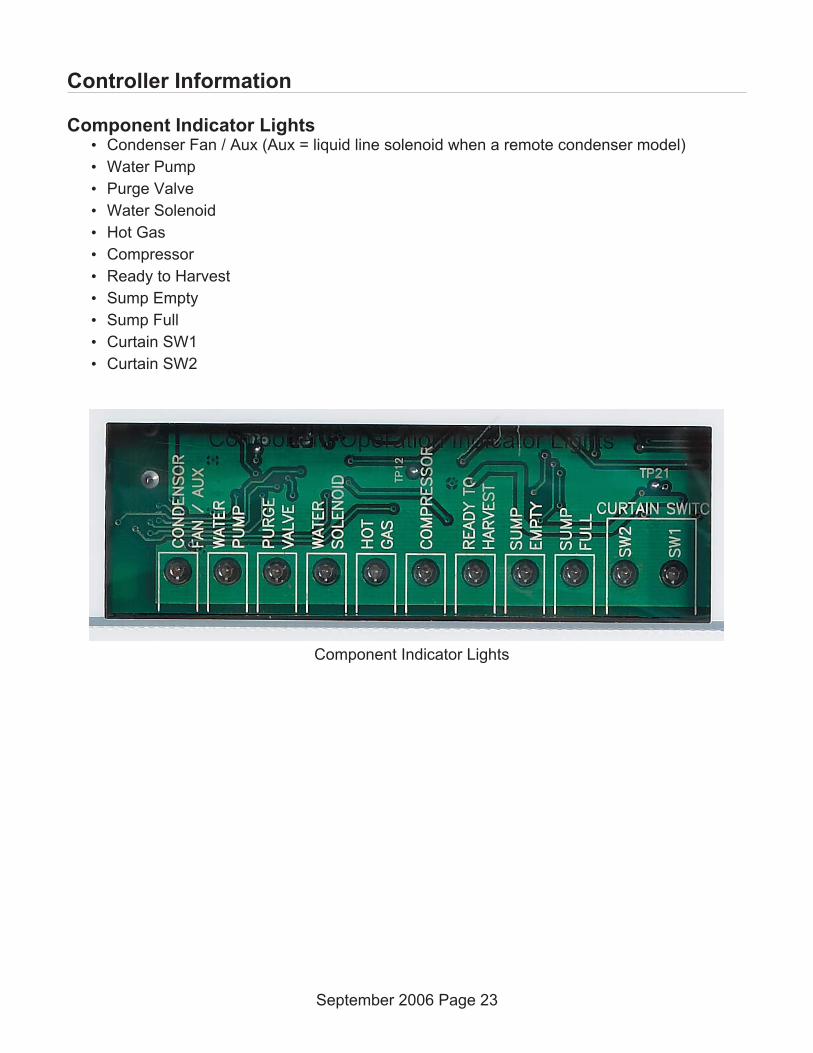
Controller Information
Component Indicator Lights• Condenser Fan / Aux (Aux = liquid line solenoid when a remote condenser model)
• Water Pump
• Purge Valve
• Water Solenoid
• Hot Gas
• Compressor
• Ready to Harvest
• Sump Empty
• Sump Full
• Curtain SW1
• Curtain SW2
September 2006 Page 23
Component Indicator Lights

How It Works - Air Cooled
Freeze Cycle. At start up the controller drains and refills the reservoir. The reservoir refillswhen the mid length water level sensor probe is uncovered and continues to fill until the topprobe is in contact with water. When the reservoir has filled, the compressor and water pumpstart. After the discharge pressure has increased past the cut in point of the fan pressurecontrol, the fan motor(s) will begin to operate and warm air will be discharged out the back ofthe cabinet. The fan motor will switch on and off as the discharge pressure rises and falls.Water flows over the evaporator as the refrigeration system begins to remove heat. When thewater temperature falls to a preset point, as measured by the water temperature sensor, thecontroller shuts off the water pump for 30 seconds. The freeze cycle resumes when the pumprestarts and ice begins to form on the evaporator. As it forms, the water flowing over the icemoves closer and closer to the metal tip of the ice thickness sensor. When it comes intocontact with the sensor for a few continuous seconds, that signals the controller that the freezecycle is complete.
The controller may shut the air cooled fan motor off for a variable period of time to build upheat for harvest. This is dependant upon the temperature of the discharge line sensor.
Harvest Cycle. When the harvest cycle begins, the controller shuts off the fan motor, switcheson the hot gas valve, and through a parallel circuit, the harvest assist solenoid. After a fewseconds the purge valve opens and water is drained from the reservoir. Based on either theautomatic purge or manual purge setting, the pump and purge valve will be switched off at atime determined to have drained enough water for that setting. The inlet water valve will opento fill the reservoir anytime the mid length probe is uncovered, which occurs during thereservoir drain cycle. Harvest continues as the hot discharge gas flows into the evaporatorserpentine, heating up the evaporator. At the same time the harvest assist solenoid is pushingagainst the back of the ice slab. When the ice releases from the evaporator, it harvests as aunit, and the harvest assist probe provides some additional force to push it off. When the icefalls off it will force the curtain(s) open. An open curtain during the harvest cycle signals thecontroller that the evaporator has released its ice. If this is a single evaporator machine thecontroller will terminate harvest. If it is a two evaporator machine, the controller will continueharvest until both curtains have opened. If one curtain remains open, the controller will shut themachine down on bin full. Anytime harvest is complete the hot gas valve and harvest assistsolenoid are shut off. The harvest assist solenoid pin returns to its normal position by springpressure.
If the curtain(s) re-close after harvest, the freeze cycle will restart.
September 2006 Page 24

How It Works - Water Cooled
Freeze Cycle. At start up the controller drains and refills the reservoir. The reservoir refillswhen the mid length water level sensor probe is uncovered and continues to fill until the topprobe is in contact with water. When the reservoir has filled, the compressor and water pumpstart. After the discharge pressure has increased past the set point of the water regulatingvalve, the water regulating valve will open and warm water will be discharged out thecondenser drain. The water regulating valve will modulate to maintain a relatively constantdischarge pressure. Water flows over the evaporator as the refrigeration system begins toremove heat. When the water temperature falls to a preset point, as measured by the watertemperature sensor, the controller shuts off the water pump for 30 seconds. The freeze cycleresumes when the pump restarts and ice begins to form on the evaporator. As it forms, thewater flowing over the ice moves closer and closer to the metal tip of the ice thickness sensor.When it comes into contact with the sensor for a few continuous seconds, that signals thecontroller that the freeze cycle is complete.
Harvest Cycle. When the harvest cycle begins, the controller switches on the hot gas valve,and through a parallel circuit, the harvest assist solenoid. After a few seconds the purge valveopens and water is drained from the reservoir. Based on either the automatic purge or manualpurge setting, the pump and purge valve will be switched off at a time determined to havedrained enough water for that setting. The inlet water valve will open to fill the reservoiranytime the mid length probe is uncovered, which occurs during the reservoir drain cycle.Harvest continues as the hot discharge gas flows into the evaporator serpentine, heating upthe evaporator. At the same time the harvest assist solenoid is pushing against the back of theice slab. When the ice releases from the evaporator, it harvests as a unit, and the harvestassist probe provides some additional force to push it off. When the ice falls off it will force thecurtain(s) open. An open curtain during the harvest cycle signals the controller that theevaporator has released its ice. If this is a single evaporator machine the controller willterminate harvest. If it is a two evaporator machine, the controller will continue harvest untilboth curtains have opened. If a curtain remains open, the controller will shut the machine downon bin full. Anytime harvest is complete the hot gas valve and harvest assist solenoid are shutoff. The harvest assist solenoid pin returns to its normal position by spring pressure.
If the curtain(s) re-close after harvest, the freeze cycle will restart.
January 2010 Page 25
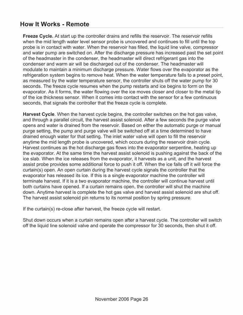
How It Works - Remote
Freeze Cycle. At start up the controller drains and refills the reservoir. The reservoir refillswhen the mid length water level sensor probe is uncovered and continues to fill until the topprobe is in contact with water. When the reservoir has filled, the liquid line valve, compressorand water pump are switched on. After the discharge pressure has increased past the set pointof the headmaster in the condenser, the headmaster will direct refrigerant gas into thecondenser and warm air will be discharged out of the condenser. The headmaster willmodulate to maintain a minimum discharge pressure. Water flows over the evaporator as therefrigeration system begins to remove heat. When the water temperature falls to a preset point,as measured by the water temperature sensor, the controller shuts off the water pump for 30seconds. The freeze cycle resumes when the pump restarts and ice begins to form on theevaporator. As it forms, the water flowing over the ice moves closer and closer to the metal tipof the ice thickness sensor. When it comes into contact with the sensor for a few continuousseconds, that signals the controller that the freeze cycle is complete.
Harvest Cycle. When the harvest cycle begins, the controller switches on the hot gas valve,and through a parallel circuit, the harvest assist solenoid. After a few seconds the purge valveopens and water is drained from the reservoir. Based on either the automatic purge or manualpurge setting, the pump and purge valve will be switched off at a time determined to havedrained enough water for that setting. The inlet water valve will open to fill the reservoiranytime the mid length probe is uncovered, which occurs during the reservoir drain cycle.Harvest continues as the hot discharge gas flows into the evaporator serpentine, heating upthe evaporator. At the same time the harvest assist solenoid is pushing against the back of theice slab. When the ice releases from the evaporator, it harvests as a unit, and the harvestassist probe provides some additional force to push it off. When the ice falls off it will force thecurtain(s) open. An open curtain during the harvest cycle signals the controller that theevaporator has released its ice. If this is a single evaporator machine the controller willterminate harvest. If it is a two evaporator machine, the controller will continue harvest untilboth curtains have opened. If a curtain remains open, the controller will shut the machinedown. Anytime harvest is complete the hot gas valve and harvest assist solenoid are shut off.The harvest assist solenoid pin returns to its normal position by spring pressure.
If the curtain(s) re-close after harvest, the freeze cycle will restart.
Shut down occurs when a curtain remains open after a harvest cycle. The controller will switchoff the liquid line solenoid valve and operate the compressor for 30 seconds, then shut it off.
November 2006 Page 26

Electrical Sequence - Air or Water Cooled
Power connected, unit previously switched Off.
Control board does a self check. If the self check fails, the unit displays an E and no furtheraction will occur.
If the self check passes, the controller will display a 0, the curtain light(s) will be ON and thePower and Sump Empty lights will be ON.
Pushing and releasing the On button will start the ice making process.
The display will begin to blink F. The component indicator lights will switch on and off to match thefollowing process:
The purge valve opens and the water pump starts to empty the reservoir. This is done todischarge any excess water from ice melting into the reservoir.
The hot gas valve and the harvest assist solenoid are energized.
The inlet water valve will open to fill the reservoir. The water valve can open any time the waterlevel is low.
After a few seconds the purge valve closes and the pump shuts off.
When the reservoir is full the inlet water valve stops and the compressor switches on. Fiveseconds after the compressor starts the hot gas valve and the harvest assist solenoid arede-energized.
Light Information: The display shows a non-blinking F. The Power and Status Lights will be Green. Thecompressor, fan motor, water pump, sump full and one or two curtain switch lights will be ON.
The air cooled model's fan motor will start to turn when the discharge pressure has built up tothe fan pressure control's cut in point. This is about 15 seconds after the compressor starts.
The Freeze cycle continues. The compressor, water pump, fan motor and curtain indicatorlights will be ON. When the reservoir water temperature falls to a certain preset point, thewater pump will shut off for 30 seconds. This is the anti-slush period. At this time the controllerchecks the conductivity of the water in the reservoir for the auto-purge feature. After the waterpump restarts the Sump Full light will go out and neither sump lights will be on for the rest ofthe freeze cycle.
When the ice has built up enough so that the water flowing over the evaporator comes intocontinuous contact with the ice level sensor, the Ready to Harvest light will begin to blink onand off. When it has been On continuously for 5 seconds, the controller will switch the machineinto a Harvest cycle.
September 2006 Page 27

Indicator Information: The display shows a non-blinking H. The Power and Status Lights will be Green.The compressor, hot gas valve and one or two curtain switch lights will be ON. After a few seconds thewater pump, purge valve and inlet water valve lights will come on.
The fan motor(s) shut off and remain off throughout the harvest cycle.
The harvest assist solenoid is connected in parallel with the hot gas valve. Although it isenergized throughout the harvest cycle, its piston does not move until the ice has becomepartially loosened from the evaporator plate by the action of the hot refrigerant gas passingthrough the evaporator serpentine.
The water pump and purge valve will shut off when the purge level setting time has beenreached, either the manual time or the automatic time. The inlet water valve will remain on untilit fills the reservoir. The Ready to Harvest light will switch Off when the ice falls from theevaporator.
Harvest continues until the ice slab is ejected from the evaporator and falls, opening thecurtain. When the curtain opens, the magnetic reed curtain switch opens, breaking the circuitto the controller. If the curtain re-closes within 30 seconds, the controller switches the machineback into another freeze cycle. If the curtain switch remains open, the controller shuts themachine down and puts it into a standby position.
September 2006 Page 28
Electrical Sequence - Air or Water Cooled

Electrical Sequence - Remote Cooled
Power connected, unit previously switched Off.
Control board does a self check. If the self check fails, the unit displays an E and no furtheraction will occur.
If the self check passes, the controller will display a 0, the curtain light(s) will be ON and thePower and Sump Empty lights will be ON.
Pushing and releasing the On button will start the ice making process.
The display will begin to blink F. The component indicator lights will switch on and off to match thefollowing process:
The purge valve opens and the water pump starts to empty the reservoir. This is done todischarge any excess water from ice melting into the reservoir.
The hot gas valve and the harvest assist solenoid are energized.
The inlet water valve will open to fill the reservoir. The water valve can open any time the waterlevel is low.
After a few seconds the purge valve closes and the pump shuts off.
When the reservoir is full the inlet water valve stops, the liquid line valve is opened and thecompressor switches on. Five seconds after the compressor starts the hot gas valve and theharvest assist solenoid are de-energized.
Light Information: The display shows a non-blinking F. The Power and Status Lights will be Green. Thecompressor, fan motor, water pump, sump full and one or two curtain switch lights will be ON.
The Freeze cycle continues. When the reservoir water temperature falls to a certain presetpoint, the water pump will shut off for 30 seconds. This is the anti-slush period. At this time thecontroller checks the conductivity of the water in the reservoir for the auto-purge feature. Afterthe water pump restarts the Sump Full light will go out and neither sump lights will be on for therest of the freeze cycle.
When the ice has built up enough so that the water flowing over the evaporator comes intocontinuous contact with the ice level sensor, the Ready to Harvest light will begin to blink onand off. When it has been On continuously for 3 seconds, the controller will switch the machineinto a Harvest cycle.
Indicator Information: The display shows a non-blinking H. The Power and Status Lights will be Green.The compressor, hot gas valve and one or two curtain switch lights will be ON. After a few seconds thewater pump, purge valve and inlet water valve lights will come on.
September 2006 Page 29
The harvest assist solenoid is connected in parallel with the hot gas valve. Although it isenergized throughout the harvest cycle, its piston does not move until the ice has becomepartially loosened from the evaporator plate by the action of the hot refrigerant gas passingthrough the evaporator serpentine.
The remote condenser fan motor is powered by the compressor contactor, so it will beoperating during the harvest cycle.
The water pump and purge valve will shut off when the purge level setting time has beenreached, either the manual time or the automatic time. The inlet water valve will remain on untilit fills the reservoir. The Ready to Harvest light will switch Off when the ice falls from theevaporator.
Harvest continues until the ice slab is ejected from the evaporator and falls, opening thecurtain. When the curtain opens, the magnetic reed curtain switch opens, breaking the circuitto the controller. If the curtain re-closes within 30 seconds, the controller switches the machineback into another freeze cycle. If the curtain switch remains open, the controller shuts themachine down and puts it into a standby position.
September 2006 Page 30
Electrical Sequence - Remote Cooled

Remote Schematics
September 2006 Page 31
Receiver
Evaporator
Compressor
Remote Condenser
Hot GasValve
Suction
Discharge Line
HeadPressureControlValve
HeatExchange
TXV
Liquid Line Valve
C0522R, C0530R, C0630R and C1030R
Receiver
Compressor
Remote Condenser
Hot GasValve
Hot GasValve
Discharge Line
Accumulator
HeadPressureControlValve
HeatExchange
Evaporator
Suction
TXV
Evaporator
Suction
TXV
Liquid Line Valve
C1448R, C1848R and C2148R

Electrical Component Details
Compressor
• Operated by the compressor contactor. Single phase self contained models have PTCRand run capacitor.
Contactor
• Operated by the controller and the high pressure cut out switch. Line voltage coil. Whenenergized the Compressor indicator light will be ON.
Water Pump
• Operated by the controller. When energized, the Water Pump indicator light will be ON.
Inlet Water Solenoid Valve
• Operated by the controller. Line voltage coil. When energized, the Water Solenoidindicator light will be ON.
Purge Valve
• Operated by the controller. Line voltage coil. When energized, the Purge Valve indicatorlight will be ON. Energized for a time during harvest.
Fan Motor(s)
• Operated by the controller and the fan pressure control. Can cycle on and off in the freezecycle, always off during harvest. When the controller has energized it, the indicator lightwill be ON but the fan will not turn unless the discharge pressure is high enough to closethe high pressure control.
• Fan(s) may shut off near the end of the freeze cycle to build up heat for harvest. Time ofshut off depends upon available heat, as measured by the discharge temperature.
High pressure cut out
• Some air cooled and all remote and all water cooled models have a high pressure cut outswitch that shuts the power off to the compressor contactor if the discharge pressure is toohigh. It is an automatic reset.
Harvest Assist Solenoid(s)
• Operated by the controller in parallel with the hot gas valve. Cycles on and off at thebeginning of a restart. Energized throughout the harvest cycle. Line voltage coil.
September 2006 Page 32

Liquid Line Valve
• Remote only. Opened by the controller to start a freeze cycle. Closed to shut unit off. Linevoltage coil.
Hot Gas Valve(s)
• Operated by the controller in parallel with the harvest assist solenoid. Cycles on and off atthe beginning of a restart. Energized throughout the harvest cycle. Line voltage coil.
Controller
• Senses ice thickness, water level, water temperature, discharge temperature. Controlscompressor contactor, fan motor, water pump, inlet water valve, hot gas valve, purgevalve, harvest assist solenoid. Indicates status and component operation. 12 volt.
Transformer
• 12 volt secondary, supplies power to controller only.
Water Level Sensor
• Three probe conductivity sensor. Bottom probe is common, mid probe is refill sump, topprobe is full sump. Refill can occur at any time.
Ice Thickness Sensor
• Single wire conductivity sensor. Circuit made from controller to ground to controller whenwater contacts a probe suspended over ice plate. Signals ready for harvest.
Curtain Switch(es)
• Magnetic reed switch. Normally open, switch is closed when magnet is nearby. Modelswith two evaporators have two curtain switches. Single switch can be connected to eitherJ8 or J7 of controller. Curtains may be removed in the freeze cycle without affectingcontroller operation. A curtain removed during harvest will cause the controller to terminateharvest and shut the unit off. Two curtain models require both curtains to open toterminate harvest, and if either one remains open for 30 seconds that signals the controllerto shut the unit off on bin full.
Water temperature sensor.
• Thermistor inserted into the water pump discharge hose. Reported temperature used bythe controller to determine anti-slush cycle start time.
January 2010 Page 33
Electrical Component Details
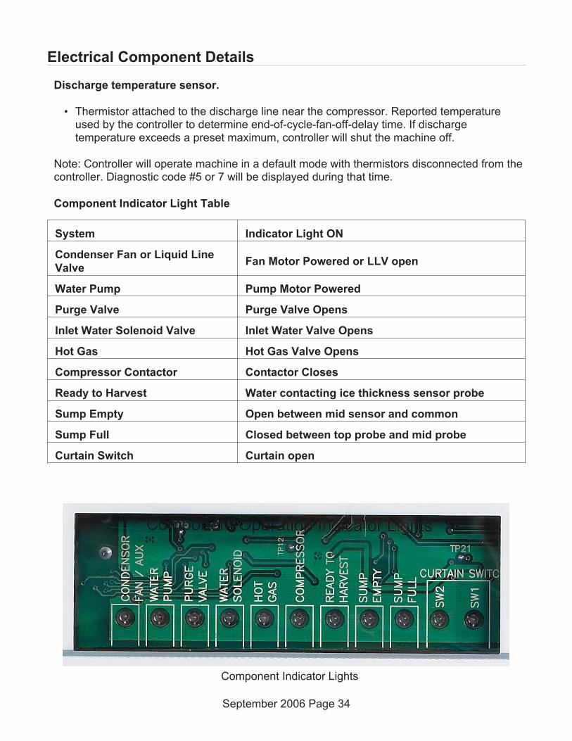
Discharge temperature sensor.
• Thermistor attached to the discharge line near the compressor. Reported temperatureused by the controller to determine end-of-cycle-fan-off-delay time. If dischargetemperature exceeds a preset maximum, controller will shut the machine off.
Note: Controller will operate machine in a default mode with thermistors disconnected from thecontroller. Diagnostic code #5 or 7 will be displayed during that time.
Component Indicator Light Table
System Indicator Light ON
Condenser Fan or Liquid Line
ValveFan Motor Powered or LLV open
Water Pump Pump Motor Powered
Purge Valve Purge Valve Opens
Inlet Water Solenoid Valve Inlet Water Valve Opens
Hot Gas Hot Gas Valve Opens
Compressor Contactor Contactor Closes
Ready to Harvest Water contacting ice thickness sensor probe
Sump Empty Open between mid sensor and common
Sump Full Closed between top probe and mid probe
Curtain Switch Curtain open
September 2006 Page 34
Electrical Component Details
Component Indicator Lights
Refrigeration
Refrigerant: R-404A
Compressors: Copeland or Tecumseh hermetic by model
Expansion valves: Non adjustable, internally equalized, one per evaporator.
Hot gas valves: Pilot operated, line voltage coils. One per plate.
Condensers: Forced draft air, counterflow water. All air cooled models have left side air inlet.48” wide air cooled models also have front air inlet. All air cooled models exhaust air out theback.
Air filters: Surface mounted to panels. Filter media removable without removing panels.
Fan blades: Reduced vibration blades in most air cooled models.
Remote Systems: Head pressure control valves in condenser. No check valves. Headmasterprotected by filters (not filter driers). Controller pumps unit down by closing the liquid line valveand keeping the compressor on for a fixed time period at shut down.
Fan pressure control. All AC. Controls fan motor operation in the freeze cycle.
High pressure cut out. WC, RC, AC with Tecumseh compressors.
Evaporator: Unified cell plate. Nickel plated copper. Three heights: 6”, 12” and 18”. Smallcube = half dice, medium cube = full dice.
Small cube: 7/8" high x 7/8" deep x 3/8" high
Medium cube: 7/8" high x 7/8" deep x 7/8" high
September 2006 Page 35

Water System
Batch type. Insulated water reservoir contains full water charge for each ice making cycle.
Water valve: Solenoid type. Opens to fill reservoir when mid sensor probe no longer makes acircuit to the bottom probe. Closes when reservoir is full and top probe makes circuit to midprobe.
Pump: Unsealed pedestal type, twist-release mounting
Water purge valve: Solenoid type. Opens to purge water during harvest cycle.
Water Level Sensor: Three probe conductivity.
Distributor: ABS plastic. Evenly distributes water over the evaporator surface. Slides off theevaporator top. Removable cover for ease of cleaning.
September 2006 Page 36
Water Distributor Removal

Control Operation
Standard control:
• Electronic controller operating from a 12 AC volt power supply. Will operate within avoltage range between 10 and 15.5.
• User’s Indicator lights, four front visible: Power, Status, Water, De-scale/Sanitize.
• Accessible On switch.
• Accessible Off switch.
• Code Display: Displays letters and numbers to indicate cycles and diagnostic codes.
• Manual Harvest switch: Use to trigger harvest at any time.
• Clean switch: Use to initiate and finish the de-scale or sanitizing cycles.
• Component Operation Indicator Lights: Indicate the status of certain components; waterlevel; ready for harvest; curtain switch position.
• Power Light: On when power is being supplied to the controller.
• Status Light: Green when machine is in ice making mode and is operating correctly. Blinksred when a machine malfunction has been detected.
• Water Light: Blinks red when reservoir does not fill with allowed time period.
• De-scale / sanitize: Yellow when the controller has determined it is time to de-scale andsanitize the machine. Use clean process to reset light. Time is determined by power uptime and controller's setting. Standard setting is 6 months. See adjustment process
Controller Connections:
• J1 – Ground and Power Supply
• J2 – High voltage power harness to loads
• J3 – Factory use
• J4 – Optional board connector
• J5 - Communications port
• J6 – Thermistor connection
• J7 – Curtain switch
• J8 – Curtain switch
• J9 – Water level sensor
• J10 – Ice thickness sensor
• J11 – Bin thermostat. Use with NO thermostat (closes on temperature fall) & specifiedharness.
September 2006 Page 37

Control Safeties
Max freeze time – 45 minutes
When exceeded, the controller will attempt another freeze cycle. If the next cycle's freeze timeis less than maximum, the control will continue normal ice making. If the next freeze cycle wastoo long, the control will again attempt another freeze cycle. If the freeze cycle is too long threeconsecutive cycles, the controller will shut the unit off and it must be manually reset.
Min freeze time – 6 minutes
If the controller switches the machine into harvest within 20 seconds of the minimum freezetime, the controller will harvest for a preset time and does not stop if the curtain switch opens.If this occurs again in the next three cycles, the machine will shut down and must be manuallyreset.
Max harvest time – 3.5 minutes
If the harvest cycle has continued for 3.5 minutes without the curtain opening, the controller willshut the machine off for 50 minutes and then restart. If there is another the machine will shutthe machine off for another 50 minutes and then restart. If it fails a third consecutive time thecontroller will shut the machine down and must be manually reset.
• Time between resets – 50 minutes
• Number of automatic resets – 2
• Max water fill time – 5 minutes. Machine will attempt a restart every 20 minutes.
• Max discharge temp – 250 degrees F.
• Time interval between cleanings – 6 months power on time - adjustable in one monthincrements, can be set at 6, 5, 4 or 3 months of power up time.
• Manual harvest time – 3 minutes
• Pump down interval – remote only. 12 hours. Pump down is 30 seconds of compressoronly on time.
• Minimum compressor off time – 4 minutes
• Continuous Run Time Maximum Cycles - 200
October 2006 Page 38

Restarts
Power Interruption
The controller will automatically restart the ice machine after adequate voltage has beenrestored.
• H blinks on code display
• Status indicator light blinks
• Reservoir is drained and refilled
Default harvest is initiated. The curtain switch does not have to open to terminate harvest,harvest will continue until the default harvest time expires. Default harvest time is 3 minutes.The machine will then return to a normal freeze cycle.
Water Interruption
• The controller will attempt to fill the reservoir every twenty minutes until it is successful.
On-Off Switch Access
All models ship with the On and Off switches front accessible. If desired, the On and Offswitches can be covered by changing the bezel in the front panel’s trim strip. A cover-up bezelships loose with the machine.
September 2006 Page 39

Control Button Use (from standby)
Set purge level, 1-5 (1 is minimum, 5 is maximum) or Automatic:
• Hold off button in for 3 seconds. Release.
• Press and release the On button to cycle through and select one of the five purge settingsor to use the Automatic setting.
Recall diagnostic code:
• Hold off button in for 3 seconds. Release.
• Press and release the Harvest button to cycle through each of the last 10 error codes frommost recent to oldest.
Clear diagnostic code:
• Hold Clean and Harvest buttons in for 3 seconds to clear all prior codes.
Reset control:
• Depress and release Off, then depress and release On
Start Test Mode:
• Hold Off button in for 3 seconds. Release.
• Hold Clean button in for 3 seconds. Release.
Lock / Unlock control:
• Hold On button in for 3 seconds, keep holding then press and release Off twice.
Empty reservoir:
• Hold Clean button in for 3 seconds. Release. Pump and purge valve will be ON for 30seconds. Repeat as needed.
Test Mode: See next page for Air and Water Cooled mode.
• Depress Off for 3 seconds, release. Then depress Clean for 3 seconds.
• The sump will fill the first 30 seconds of the test. If the sump is full it will overflow into thebin. At 30 seconds the WIV will shut off and the WP will turn on. You will be able to seeand hear the water running over the plates. After 10 seconds the PV and HGV will turnon. Water will be purging from the machine. After 10 more seconds the compressor willstart. 5 seconds later the HGV will close. The compressor will run for a total of 20seconds. After which everything will turn off for 5 seconds. After that time the HGV willopen and you’ll be able to hear the hissing as the pressure is equalized. 10 seconds laterthe fan will turn on (if air cooled and fan control jumped). After 10 seconds all will be offand the output test will be complete.
September 2006 Page 40

Change De-Scale Notification Interval
Like the others, this feature is accessible only from standby (Status Light Off).
1. Press and hold harvest button for 3 seconds.
Starts the Time to Clean Adjustment State and displays the current time to clean setting.
2. Press the clean button repeatedly to cycle through the 4 possible settings:
Rev 5 and up (10/08 production start)
• 1 year (8760 hours)
• 0 (disabled)
• 4 months (2920 hrs)
• 6 months (4380 hours) (default)
Prior
• 6 months
• 5 months
• 4 months
• 3 months
3. Press Off or leave untouched for 60 seconds to select the displayed interval
Test Mode Sequence Table - Air or Water Cooled
Time (seconds) On Off
0 WIV - 30 seconds WP, HGV, Comp, Fan, PV
30 WP - 10 seconds WIV, HGV, Comp, Fan, PV
40 WP, PV, HGV - 10 seconds WIV, Comp, Fan
50 HGV, Comp - 5 seconds WIV, WP, Fan, PV
55 Comp - 15 seconds WIV, HGV, WP, Fan, PV
70 None - 5 seconds All
75 HGV - 10 seconds WIV, WP, Comp, Fan, PV
85 Fan - 10 seconds WIV, HGV, WP, Comp, PV
95 None All – Test Complete
October 2008 Page 41
Control Button Use - continued

Diagnostics – Air Cooled
No ice
Problem Likely Cause Probable Solution
No power to unit Power disconnectedCheck breaker or fuse. Resetor replace, restart and check
No power to controller Transformer open Replace transformer
Shut down onmaximum water filltime
Water shut off Restore water supply
Shut down onmaximum freeze time
Water leakCheck purge valve, curtain,sump, pump hose
Air filters clogged Clean air filters
Dirty condenser Clean condenser
Restricted location, intake airtoo hot
Have machine moved
Ice thickness sensor dirty ordisconnected
Check ice thickness sensorprobe
Water distributor dirtyRemove and clean waterdistributor
Inlet water valve leaks throughduring freeze
Check inlet water valve
Connected to hot waterCheck for bleed thru from /missing check valve in buildingwater supply
Incomplete harvest Check harvest system
High pressure cut out openedCheck fan motor pressurecontrol, check fan motor, checkcontroller using test mode
Fan motor pressure controlopen
Check fan pressure control
Fan motor not turningCheck fan motor, check fanblade, check controller usingtest mode
Water pump not pumping
Check pump motor, checkcontroller using test mode
September 2006 Page 42

Problem Likely Cause Probable Solution
Shut down onmaximum freeze time
Pump hose disconnected Check hose
Compressor not operating
Check compressor contactor,check controller using testmode
Check compressor startcomponents, check PTCRresistance and temperature
Check compressor voltage
Check compressor windings
Low refrigerant chargeAdd some refrigerant andrestart unit. If cycle timeimproves, look for leak.
Hot gas valve leaks throughduring freeze
Check hot gas valve for hotoutlet during freeze
Thermostatic expansion valvebulb loose
Check bulb
Thermostatic expansion valveproducing very low or very highsuperheat
Check evaporator superheat,change TXV if incorrect
Compressor inefficientCheck compressor amp draw,if low and all else is correct,change compressor
September 2006 Page 43
Diagnostics – Air Cooled
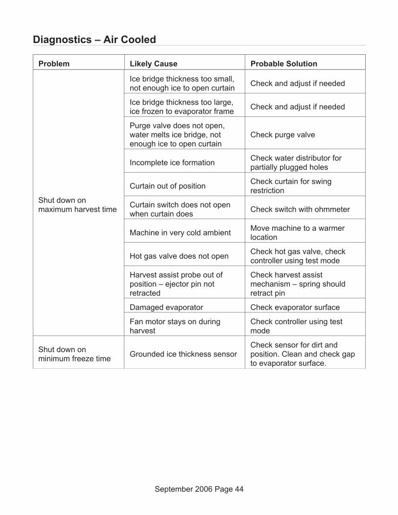
Shut down onmaximum harvest time
Ice bridge thickness too small,not enough ice to open curtain
Check and adjust if needed
Ice bridge thickness too large,ice frozen to evaporator frame
Check and adjust if needed
Purge valve does not open,water melts ice bridge, notenough ice to open curtain
Check purge valve
Incomplete ice formationCheck water distributor forpartially plugged holes
Curtain out of positionCheck curtain for swingrestriction
Curtain switch does not openwhen curtain does
Check switch with ohmmeter
Machine in very cold ambientMove machine to a warmerlocation
Hot gas valve does not openCheck hot gas valve, checkcontroller using test mode
Harvest assist probe out ofposition – ejector pin notretracted
Check harvest assistmechanism – spring shouldretract pin
Damaged evaporator Check evaporator surface
Fan motor stays on duringharvest
Check controller using testmode
Shut down onminimum freeze time
Grounded ice thickness sensorCheck sensor for dirt andposition. Clean and check gapto evaporator surface.
September 2006 Page 44
Diagnostics – Air Cooled
Problem Likely Cause Probable Solution

Low Ice Making Capacity - Air Cooled
Long freeze cycle
Dirty air filters Clean filters
Dirty condenser Clean condenser
Hot ambient Reduce room air temperature
Water leakCheck purge valve, checkcurtain
Water inlet valve leaks through Check inlet valve
Low on refrigerantAdd refrigerant, if cycle timedrops, check for leak
Incorrect superheatCheck evaporator superheat, ifsignificantly low or high,replace TXV
Fan(s) cycle on and offCheck pressures fans cycle at.Replace fan pressure switch iftoo low
Long Harvest Cycle
Dirty evaporator De-scale water system
No harvest assist Check harvest assist solenoid
Bridge thickness too bigCheck and adjust bridgethickness
Machine in very cool ambient Increase room temperature
False bin full signal
Ice jammed in between curtainand sump
Clear ice away
Curtain does not close correctly Check curtain for proper swing
September 2006 Page 45
Problem Likely Cause Probable Solution

Makes Excessive Noise - Air Cooled
Fan blade vibratesBlade is bent Replace fan blade
Fan motor mount is broken Replace motor mount
Compressor vibrates Mounting bolts loose Tighten bolts
Water pump vibrates Pump bearings worn Replace pump
Panels vibrate Mounting screws loose Tighten screws
September 2006 Page 46
Problem Likely Cause Probable Solution

Diagnostics - Water Cooled
No Ice
Problem Likely Cause Probable Solution
No power to unit Power disconnectedCheck breaker or fuse. Resetor replace, restart and check
No power to controller Transformer open Replace transformer
Shut down onmaximum water filltime
Water shut off Restore water supply
Shut down onmaximum freeze time
Water leakCheck purge valve, curtain,sump, pump hose
Ice thickness sensor dirty ordisconnected
Check ice thickness sensorprobe
Water distributor dirtyRemove and clean waterdistributor
Inlet water valve leaks throughduring freeze
Check inlet water valve
Connected to hot waterCheck for bleed thru from /missing check valve in buildingwater supply
Incomplete harvest Check harvest system
High pressure cut out openedWater supply cut off, restorewater supply to condenser
Water pump not pumpingCheck pump motor, checkcontroller using test mode
Pump hose disconnected Check hose
Compressor not operating
Check compressor contactor,check controller using testmode
Check compressor startcomponents, check PTCRresistance and temperature
Check compressor voltage
Check compressor windings
September 2006 Page 47

Shut down onmaximum freeze time
Low refrigerant chargeAdd some refrigerant andrestart unit. If cycle timeimproves, look for leak.
Hot gas valve leaks throughduring freeze
Check hot gas valve for hotoutlet during freeze
Thermostatic expansion valvebulb loose
Check bulb
Thermostatic expansion valveproducing very low or very highsuperheat
Check evaporator superheat,change TXV if incorrect
Compressor inefficientCheck compressor amp draw,if low and all else is correct,change compressor
Shut down onmaximum harvest time
Ice bridge thickness too small,not enough ice to open curtain
Check and adjust if needed
Ice bridge thickness too large,ice frozen to evaporator frame
Check and adjust if needed
Purge valve does not open,water melts ice bridge, notenough ice to open curtain
Check purge valve
Incomplete ice formationCheck water distributor forpartially plugged holes
Curtain out of positionCheck curtain for swingrestriction
Curtain switch does not openwhen curtain does
Check switch with ohmmeter
Machine in very cold ambientMove machine to a warmerlocation
Hot gas valve does not openCheck hot gas valve, checkcontroller using test mode
Harvest assist probe out ofposition – ejector pin notretracted
Check harvest assistmechanism – spring shouldretract pin
Damaged evaporatorCheck evaporator surface
September 2006 Page 48
Problem Likely Cause Probable Solution
Diagnostics - Water Cooled

Shut down onminimum freeze time
Grounded ice thickness sensorCheck sensor for dirt andposition. Clean and check gap.
Test Mode Sequence: - Air or Water Cooled
Time (seconds) On Off
0 WIV - 30 seconds WP, HGV, Comp, Fan, PV
30 WP - 10 seconds WIV, HGV, Comp, Fan, PV
40 WP, PV, HGV - 10 seconds WIV, Comp, Fan
50 HGV, Comp - 5 seconds WIV, WP, Fan, PV
55 Comp - 15 seconds WIV, HGV, WP, Fan, PV
70 None - 5 seconds All
75 HGV - 10 seconds WIV, WP, Comp, Fan, PV
85 Fan - 10 seconds WIV, HGV, WP, Comp, PV
95 None All – Test Complete
September 2006 Page 49
Problem Likely Cause Probable Solution
Diagnostics - Water Cooled
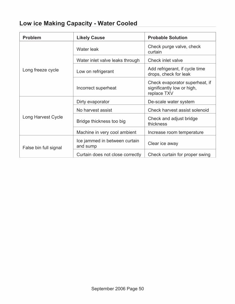
Low ice Making Capacity - Water Cooled
Long freeze cycle
Water leakCheck purge valve, checkcurtain
Water inlet valve leaks through Check inlet valve
Low on refrigerantAdd refrigerant, if cycle timedrops, check for leak
Incorrect superheatCheck evaporator superheat, ifsignificantly low or high,replace TXV
Long Harvest Cycle
Dirty evaporator De-scale water system
No harvest assist Check harvest assist solenoid
Bridge thickness too bigCheck and adjust bridgethickness
Machine in very cool ambient Increase room temperature
False bin full signal
Ice jammed in between curtainand sump
Clear ice away
Curtain does not close correctly Check curtain for proper swing
September 2006 Page 50
Problem Likely Cause Probable Solution

Makes Excessive Noise - Water Cooled
Compressor vibrates Mounting bolts loose Tighten bolts
Water pump vibrates Pump bearings worn Replace pump
Panels vibrate Mounting screws loose Tighten screws
September 2006 Page 51
Problem Likely Cause Probable Solution
Diagnostics - Remote Air Cooled
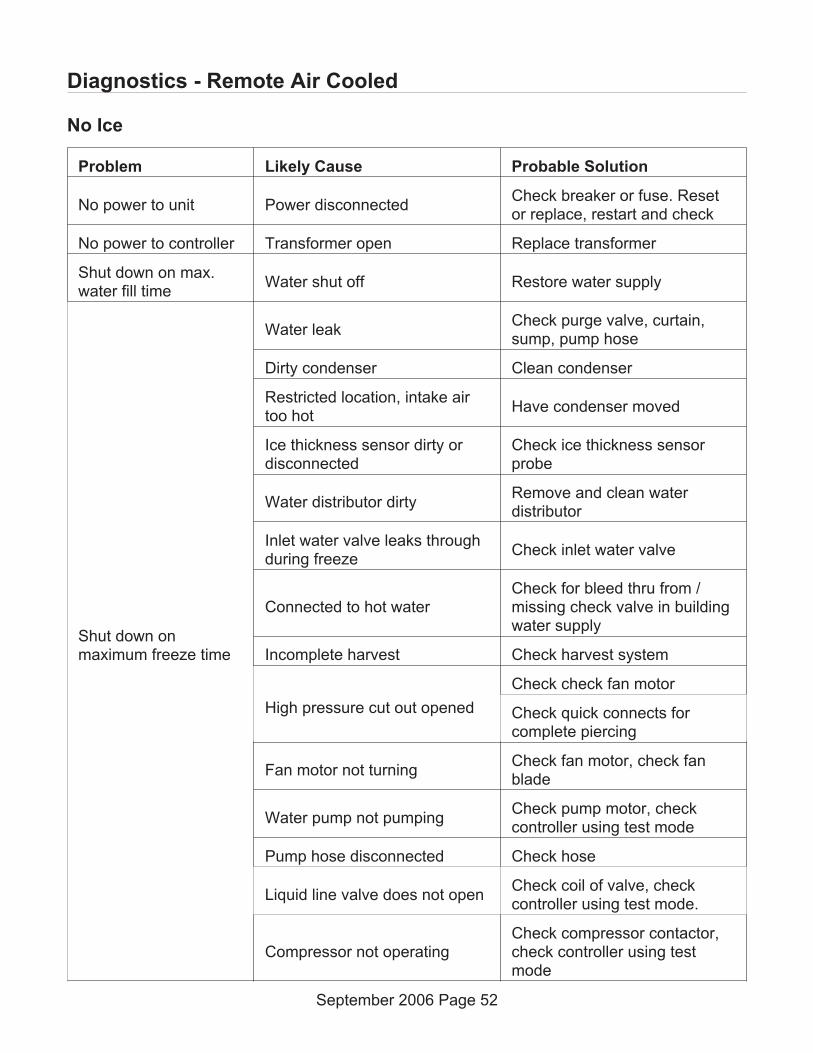
No Ice
Problem Likely Cause Probable Solution
No power to unit Power disconnectedCheck breaker or fuse. Resetor replace, restart and check
No power to controller Transformer open Replace transformer
Shut down on max.water fill time
Water shut off Restore water supply
Shut down onmaximum freeze time
Water leakCheck purge valve, curtain,sump, pump hose
Dirty condenser Clean condenser
Restricted location, intake airtoo hot
Have condenser moved
Ice thickness sensor dirty ordisconnected
Check ice thickness sensorprobe
Water distributor dirtyRemove and clean waterdistributor
Inlet water valve leaks throughduring freeze
Check inlet water valve
Connected to hot waterCheck for bleed thru from /missing check valve in buildingwater supply
Incomplete harvest Check harvest system
High pressure cut out opened
Check check fan motor
Check quick connects forcomplete piercing
Fan motor not turningCheck fan motor, check fanblade
Water pump not pumpingCheck pump motor, checkcontroller using test mode
Pump hose disconnected Check hose
Liquid line valve does not openCheck coil of valve, checkcontroller using test mode.
Compressor not operatingCheck compressor contactor,check controller using testmode
September 2006 Page 52
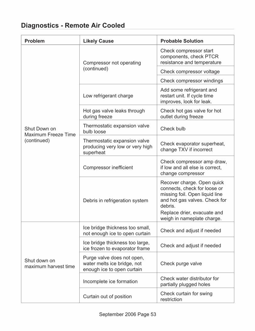
Shut Down onMaximum Freeze Time(continued)
Compressor not operating(continued)
Check compressor startcomponents, check PTCRresistance and temperature
Check compressor voltage
Check compressor windings
Low refrigerant chargeAdd some refrigerant andrestart unit. If cycle timeimproves, look for leak.
Hot gas valve leaks throughduring freeze
Check hot gas valve for hotoutlet during freeze
Thermostatic expansion valvebulb loose
Check bulb
Thermostatic expansion valveproducing very low or very highsuperheat
Check evaporator superheat,change TXV if incorrect
Compressor inefficientCheck compressor amp draw,if low and all else is correct,change compressor
Debris in refrigeration system
Recover charge. Open quickconnects, check for loose ormissing foil. Open liquid lineand hot gas valves. Check fordebris.
Replace drier, evacuate andweigh in nameplate charge.
Shut down onmaximum harvest time
Ice bridge thickness too small,not enough ice to open curtain
Check and adjust if needed
Ice bridge thickness too large,ice frozen to evaporator frame
Check and adjust if needed
Purge valve does not open,water melts ice bridge, notenough ice to open curtain
Check purge valve
Incomplete ice formationCheck water distributor forpartially plugged holes
Curtain out of positionCheck curtain for swingrestriction
September 2006 Page 53
Problem Likely Cause Probable Solution
Diagnostics - Remote Air Cooled

Shut down onmaximum harvest time(continued)
Curtain switch does not openwhen curtain does
Check switch with ohmmeter
Machine in very cold ambientMove machine to a warmerlocation
Hot gas valve does not openCheck hot gas valve, checkcontroller using test mode
Harvest assist probe out ofposition – ejector pin notretracted
Check harvest assistmechanism – spring shouldretract pin
Damaged evaporator Check evaporator surface
Shut down onminimum freeze time
Grounded ice thickness sensor
Check sensor for dirt andposition. Clean and adjust gapto evaporator surface using13/64” drill bit as a gauge
September 2006 Page 54
Problem Likely Cause Probable Solution
Diagnostics - Remote Air Cooled

Low Ice Making Capacity - Remote
Long freeze cycle
Dirty condenser Clean condenser
Hot ambient Check condenser inlet temp.
Water leakCheck purge valve, checkcurtain
Water inlet valve leaks through Check inlet valve
Low on refrigerantAdd refrigerant, if cycle timedrops, check for leak
Incorrect superheatCheck evaporator superheat, ifsignificantly low or high,replace TXV
Fan(s) cycle on and offCheck pressures fans cycle at.Replace fan pressure switch iftoo low
Long Harvest Cycle
Dirty evaporator De-scale water system
No harvest assist Check harvest assist solenoid
Bridge thickness too bigCheck and adjust bridgethickness
Machine in very cool ambient Increase room temperature
False bin full signal
Ice jammed in between curtainand sump
Clear ice away
Curtain does not close correctly Check curtain for proper swing
September 2006 Page 55
Problem Likely Cause Probable Solution

Makes Excessive Noise - Remote
Fan blade vibratesBlade is bent Replace fan blade
Fan motor mount is broken Replace motor mount
Compressor vibrates Mounting bolts loose Tighten bolts
Water pump vibrates Pump bearings worn Replace pump
Panels vibrate Mounting screws loose Tighten screws
Test Mode Sequence - Remote
Test Time (seconds) On Off
0 WIV - 30 seconds WP, HGV, Comp, BV, PV
30 WP - 10 seconds WIV, HGV, Comp, BV, PV
40WP, PV, HGV - 10seconds
WIV, Comp, BV
50 HGV, Comp - 5 seconds WIV, WP, BV, PV
55 Comp - 15 seconds WIV, HGV, BV, WP, PV
70 None - 5 seconds All
75 HGV - 5 seconds WIV, WP, Comp, BV, PV
80 BV - 5 seconds WIV, HGV, WP, Comp, PV
85 None All – Test Complete
September 2006 Page 56
Problem Likely Cause Probable Solution
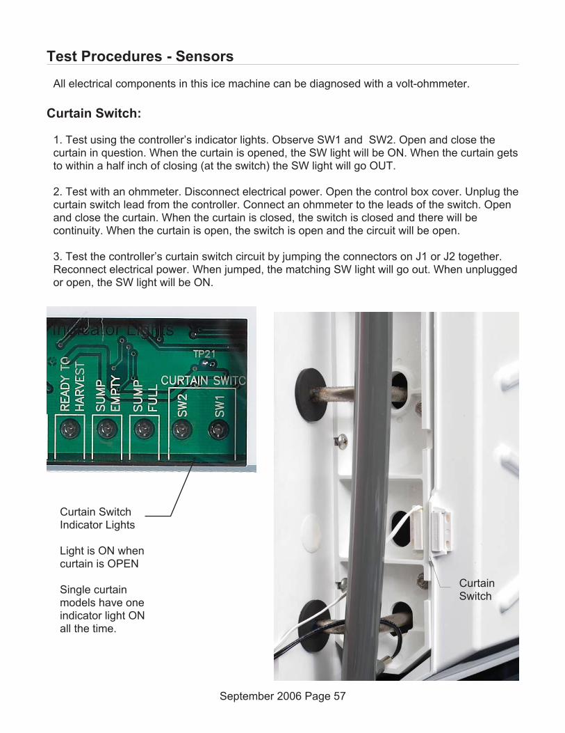
Test Procedures - Sensors
All electrical components in this ice machine can be diagnosed with a volt-ohmmeter.
Curtain Switch:
1. Test using the controller’s indicator lights. Observe SW1 and SW2. Open and close thecurtain in question. When the curtain is opened, the SW light will be ON. When the curtain getsto within a half inch of closing (at the switch) the SW light will go OUT.
2. Test with an ohmmeter. Disconnect electrical power. Open the control box cover. Unplug thecurtain switch lead from the controller. Connect an ohmmeter to the leads of the switch. Openand close the curtain. When the curtain is closed, the switch is closed and there will becontinuity. When the curtain is open, the switch is open and the circuit will be open.
3. Test the controller’s curtain switch circuit by jumping the connectors on J1 or J2 together.Reconnect electrical power. When jumped, the matching SW light will go out. When unpluggedor open, the SW light will be ON.
September 2006 Page 57
Curtain SwitchIndicator Lights
Light is ON whencurtain is OPEN
Single curtainmodels have oneindicator light ONall the time.
CurtainSwitch

Ice Thickness Sensor
1. Test using the controller’s indicator light. Observe the Ready To Harvest light. Shut themachine off. Use a wire to connect the metal part of the Ice Thickness sensor to theevaporator or simply remove the Ice Thickness Sensor and touch its metal surface to the metalcontrol box wall. The Ready for Harvest light should go ON.
2. Test with an Ohmmeter. Disconnect electrical power. Open the control box cover. Unplugthe ice thickness sensor lead from the controller. Connect an ohmmeter lead to the icethickness sensor lead, touch the other ohmmeter lead to the ice machine chassis. There mustbe an open circuit. If there is continuity, the sensor must be replaced. If there is no continuity,touch the ohmmeter lead to the metal part of the ice thickness sensor. There should becontinuity. If open, check the ice thickness sensor for scale build up. Clean and recheck. If stillopen, replace the ice thickness sensor.
3. Test the controller’s ice thickness sensor circuit by connecting a wire from J10 to ground.Reconnect electrical power. The Ready for Harvest light should go ON.
September 2006 Page 58
Ready To Harvestlight is ON whenwater contacts icethickness sensor. Ice
ThicknessSensor

Water Level Sensor
1. Test using the controller’s indicator lights (sump empty and sump full). Unit must bepowered up and there must be water in the sump. Add some manually if needed. Locate waterlevel sensor. Release from sump cover and slowly lift up until the mid-length probe is out of thewater. The sump empty light should come on, and if the unit is on the inlet water solenoid valvewill open to fill the reservoir. Return the water level sensor to its normal position. If the unit ison and calling for ice the water will fill until the top probe is in contact with it, at that time thesump full light will switch ON.
2. Test with an ohmmeter. Disconnect electrical power. Open the control box cover. Unplug theconnector at J9. Locate water level sensor and remove it from the sump cover. Test 1: Placeone lead of the ohmmeter on the longest probe and the other on the controller end of the redwire, there should be continuity. Test 2: Place one lead on the controller end of the white wireand the other on the mid-length probe, there should be continuity. Test 3: Place on lead on thecontroller end of the black wire and the other on the shortest probe, there should be continuity.If not, clean the probes and recheck.
3. Test the controller’s water level sensor circuit. Reconnect electrical power. Unplug harnessfrom water level sensor, the sump emptylight should be ON. Jump harness wireswhite and black. The sump full light shouldbe ON. Jump harness wires white and red,the sump full and sump empty lights will beOFF. Check harness wire by wire forcontinuity if there is no reaction from thecontroller during this test.
December 2008 Page 59
SumpEmpty Light
Sump FullLight

Temperature Sensors
1. Check controller. If the sensor calibration is completely out of range, the code display willread either 5 or 7.
2. Check with an ohmmeter. Open control box cover, unplug sensor from J6. Watertemperature probe: Measure the temperature of the water. Push and release the clean button.Wait one minute. Measure the resistance of the water probe (two leads next to the opensocket) and compare to the resistance in the chart for that temperature. Any reading within1000 ohms is acceptable. Discharge sensor: Measure the temperature of the discharge line asclose to the sensor as possible. Measure the resistance of the discharge temperature sensor(two leads farthest away from the open socket on the harness connector) and compare to theresistance in the chart for that temperature. Any reading within 1000 ohms is acceptable.
3. Alternate procedure: Remove both water and discharge sensors from their places on the icemachine. Put both into a container of ice water. Put a thermometer in the water. When thethermometer is at 32 degrees F., check the resistance of each sensor. The resistance shouldbe within 1000 ohms of 32649.
September 2006 Page 60
WaterTemperatureSensor Set
DischargeTemperatureSensor Set
Back of Controller

Test Procedures - Loads
Compressor
Failure to start.
Single phase models. All have resistance start, capacitor run type motors. Check voltage tocompressor at the contactor. Compare the idle voltage (compressor off) to the active voltage(compressor starting). The supply voltage must not be less than the lowest rated voltage forthe ice machine. If the voltage is correct, proceed to the next step.
Check starting components. Most models use a PTCR to cut power to the start winding afterthe compressor has started. Check the PTCR for resistance. The resistance check must bewhen the PTCR is at room temperature – any temperature between 50 and 100.
At that temperature resistance should be very low between 25 and 50 ohms. Also checkresistance to ground, it should be infinite. If the PTCR is good, check the compressor windings.
Measure resistance from Common to ground. It should be infinite. Measure resistance fromCommon to Run – compare to the chart. Measure resistance from Common to Start – compareto the chart.
Compressor check for high amp draw. Measure amp draw of starting circuit. If it does not dropoff immediately after start up, the PTCR should be replaced. It is not practical to check a PTCRfor resistance at high temperatures as the resistance drops very fast as the PTCR’stemperature falls. If the compressor is drawing excessive amps but is operating, the runcapacitor may be open. Disconnect electrical power, discharge the capacitor and measure itsresistance. If open, replace it. If shorted to ground, replace it.
Any time the compressor is replaced, the PTCR and run capacitor should also be replaced, orif the model was equipped with a potential relay, start capacitor and run capacitor, thoseshould be replaced with the compressor. Most Scotsman service compressors include thoseparts.
Some systems use a potential start relay and start capacitor in place of the PTCR.
Potential relay. If the compressor will not start, check the amp draw of the starting circuit. Ifvery low, the potential relay contacts or start capacitor may be open. Measure the resistance ofthe potential relay contacts and the start capacitor. If either is open it should be replaced. If thecompressor starts but draws very high amps from the starting circuit, the potential relay maynot switch off. In that case the relay should be replaced.
September 2006 Page 61

Resistance reading tolerance is +- 10%
Ice Machine Voltage/Hz/Phase CompressorStart Winding
Ohms
Run Winding
Ohms
C0330-1 115/60/1 AKA9438ZXA 4.22 .59
C0330-6 230/50 AKA9438ZXC 7.11 2.69
C0330-32 208-230/60/1 AKA9468ZXD 10.43 1.77
C0530-1 A or B 115/60/1 AKA9451ZXA 5.95 .69
C0530-6 A or B 230/50 AKA9451ZXC 7.11 2.69
C0530-32 A or B 208-230/60/1 AKA9451ZXD 10.43 1.77
C0530 -1 C 115/60/1 RST45C1E-CAA
C0530 - 6 C 230/50/1 RST45C1E-CAB
C0530 - 32 C 208-230/60/1 RST45C1E-CAV
C0630-32 208-230/60/1 AJA7490ZXD 2.74 1.52
C0630-6 230/50 AJA7490ZXC 2.23 2.02
C0830-32 208-230/60/1 CS10K6EPFV 3.10 1.16
C0830-6 230/50 CS10K6EPFJ 3.79 1.39
C0830-3 208-230/60/3 CS10K6ETF5 - 1.77
C1030-32 208-230/60/1 CS12K6EPFV 3.10 1.16
C1030-6 230/50 CS12K6EPFJ 3.79 1.39
C1030-3 208-230/60/3 CS12K6ETF5 - 1.77
C1448-32 208-230/60/1 CS14K6EPFV 2.66 1.08
C1448-6 230/50 CS14KSEPFJ 2.64 1.4
C1448-3 208-230/60/3 CS14K6ETF5 - -
C1848-32 208-230/60/1 CS20K6EPFV 2.37 .65
C1848-6 230/50 CS20K6EPFZ
C1848-3 208-230/60/3 CS20K6ETF5 - -
C2148-32 WC 208-230/60/1 CS24K6EPFV 2.35 .53
C2148-6 WC 230/50 CS24K6EPFZ
C2148-3 WC 208-230/60/3 CS24K6ETF5 - -
C2148-32 R 208-230/60/1 CS27K6EPFV 2.35 .53
C2148-6 R 230/50 CS27K6EPFZ
C2148-32 R 208-230/60/3 CS27K6ETF5 - -
May 2011 Page 62
Compressor Electrical Chart

Refrigerant Charges
May 2011 Page 63
Model R-404A in ounces
C0322A 14
C0322W 11
C0330A 14
C0330W 11
C0522A 17
C0522W 14
C0522R 160
C0530A (A or B series) 22
C0530A C series 21
C0530W (A thru C series) 11
C0530R (A thru C series) 160
C0630A 36
C0630W 14
C0630R 160
C0830A 46
C0830W 34
C0830R 208
C1030A 48
C1030W 38
C1030R 208
C1448A 62
C1448W 56
C1448R 256
C1848A 62
C1848W 63
C1848R 320
C2148W 69
C2148R 320
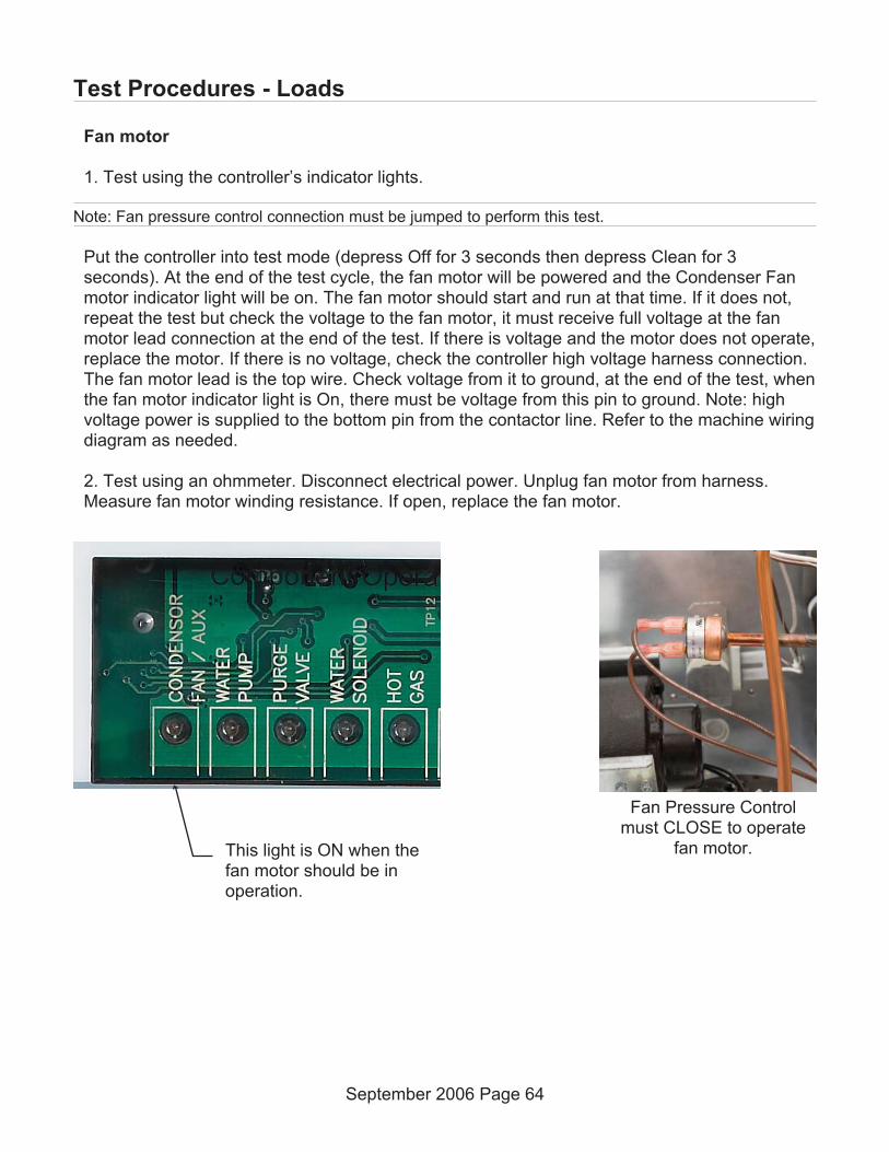
Fan motor
1. Test using the controller’s indicator lights.
Note: Fan pressure control connection must be jumped to perform this test.
Put the controller into test mode (depress Off for 3 seconds then depress Clean for 3seconds). At the end of the test cycle, the fan motor will be powered and the Condenser Fanmotor indicator light will be on. The fan motor should start and run at that time. If it does not,repeat the test but check the voltage to the fan motor, it must receive full voltage at the fanmotor lead connection at the end of the test. If there is voltage and the motor does not operate,replace the motor. If there is no voltage, check the controller high voltage harness connection.The fan motor lead is the top wire. Check voltage from it to ground, at the end of the test, whenthe fan motor indicator light is On, there must be voltage from this pin to ground. Note: highvoltage power is supplied to the bottom pin from the contactor line. Refer to the machine wiringdiagram as needed.
2. Test using an ohmmeter. Disconnect electrical power. Unplug fan motor from harness.Measure fan motor winding resistance. If open, replace the fan motor.
September 2006 Page 64
Test Procedures - Loads
This light is ON when thefan motor should be inoperation.
Fan Pressure Controlmust CLOSE to operate
fan motor.

Water Pump
1. Test using the controller’s indicator lights. Check the indicator light during the freeze cycle.The light will be On for all but the 30 second anti-slush period, so observe the light for oneminute. When it is On, check the water pump, it should be operating. If not, check voltage tothe pump. If low check the voltage from the controller to ground. The water pump pin isnumber 6. If there is voltage at that pin to ground, but very low voltage at the pump motor,there must be a broken wire in the harness. If the voltage is low at pin 6, the controller shouldbe replaced.
2. Test using an ohmmeter. Disconnect electrical power. Unplug the water pump motor leadsfrom the harness. Measure the resistance of the motor windings. If open, replace the pump.Measure resistance to ground. If there is any, replace the pump.
September 2006 Page 65
Test Procedures - Loads
Water pump light is ON whenpump is in operation.

Purge valve
1. Test using the controller’s indicator lights. Shut unit off by holding the Off button for 3seconds. Wait four minutes. Push and release the On button, observe the Purge Valveindicator light. As the unit drains the reservoir, the purge valve will be powered. When it getspower, the indicator light will be ON. If the purge valve does not open to drain the reservoirwhen its indicator light is on, do a voltage check. Shut the unit down by holding the Off buttonin for 3 seconds. Unplug the harness connection from the purge valve. Wait four minutes. Pushand release the On button to restart the machine. As the unit drains the reservoir, the purgevalve connection should receive full voltage. If it does, the purge valve should be replaced. Ifthere is no voltage, check voltage from the controller to ground. The purge valve pin is 3 (dumpvalve on wiring diagram). If there is voltage from that pin to ground, but low voltage at the valveharness connection, the harness has a broken wire or poor connection and must be replaced.If the voltage to ground is low, the controller should be replaced.
Note: The coil of this valve is internally rectified, and will normally show infinite resistance when testedwith an ohmmeter.
September 2006 Page 66
Test Procedures - Loads
This light will be ONwhen the Purge Valve isin operation.
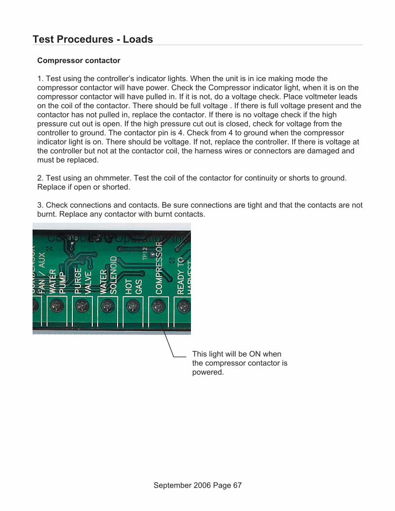
Compressor contactor
1. Test using the controller’s indicator lights. When the unit is in ice making mode thecompressor contactor will have power. Check the Compressor indicator light, when it is on thecompressor contactor will have pulled in. If it is not, do a voltage check. Place voltmeter leadson the coil of the contactor. There should be full voltage . If there is full voltage present and thecontactor has not pulled in, replace the contactor. If there is no voltage check if the highpressure cut out is open. If the high pressure cut out is closed, check for voltage from thecontroller to ground. The contactor pin is 4. Check from 4 to ground when the compressorindicator light is on. There should be voltage. If not, replace the controller. If there is voltage atthe controller but not at the contactor coil, the harness wires or connectors are damaged andmust be replaced.
2. Test using an ohmmeter. Test the coil of the contactor for continuity or shorts to ground.Replace if open or shorted.
3. Check connections and contacts. Be sure connections are tight and that the contacts are notburnt. Replace any contactor with burnt contacts.
September 2006 Page 67
Test Procedures - Loads
This light will be ON whenthe compressor contactor ispowered.

Pressure switches
There are two pressure switches: Fan and High Pressure cut out.
Fan. The fan pressure switch will open to shut the fan motor off at a certain pressure andre-close at a preset higher pressure.
High pressure cut out. The high pressure cut out switch will open at a preset pressure, shuttingoff power to the compressor contactor. After the pressure has fallen to another preset level, theswitch will re-close and the contactor coil will be engergized.
To Test Fan Pressure Switch:
A. Attach refrigeration gauge set to high side port.
B. Unplug both wires from fan pressure control. Be SURE the wire's terminals are wrapped
in electrical tape to prevent short circuits to ground during the test.
C. Connect ohmmeter to terminals of fan pressure control..
D. Switch ice machine on, observe pressure that the pressure control closes at, compare tospec. Switch unit off, allow system to equalize, observe pressure the pressure control opensat, compare to spec.
To Test High Pressure Switch:
A. Attach refrigeration gauge set to high side port.
B. Unplug fan motor or shut water off if water cooled.
C. Measure voltage between contactor side terminal of high pressure control and ground.
D. Switch ice machine on, observe pressure that the pressure control opens at, compare tospec. Allow system to equalize, observe the pressure that the pressure control closes at,compare to spec.
Transformer
Check secondary voltage, it must be between 10 and 15.5 AC volts. Replace if no voltage isoutput or if above or below the acceptable voltage..
Controller
The controller’s software operation is confirmed if it is functioning. Execute the test to confirmits operation of the loads. Illumination of a diagnostic code (other than E) is not an indication ofcontroller failure. Each code requires its own diagnosis.
September 2006 Page 68
Test Procedures - Loads

Liquid Line Solenoid (remote only)
1. Test using the controller’s indicator lights. Put the controller into test mode (depress Off for 3seconds then depress Clean for 3 seconds). At the end of the test cycle, the liquid line valvewill be powered and the Condenser Fan motor indicator light will be on. The liquid line valveshould be open at that time. If it is not, repeat the test but check the voltage to the liquid linevalve coil, it must receive full voltage at the liquid line lead connection at the end of the test. Ifthere is voltage and the valve does not operate, replace the valve coil. If there is no voltage,check the controller high voltage harness connection. The liquid line solenoid lead is the topwire. Check voltage from it to ground, at the end of the test, when the Condenser Fan indicatorlight is On, there must be voltage from this pin to ground. Note: high voltage power is suppliedto the bottom pin from the contactor line. Refer to the machine wiring diagram as needed.
2. Test using an ohmmeter. Disconnect electrical power. Unplug liquid line coil from harness.Measure liquid line coil resistance. If open, replace the liquid line valve coil.
September 2006 Page 69
Test Procedures - Loads
This light will be ON when the liquid linesolenoid has power.

Inlet Water Solenoid Valve
1. Test using the controller’s indicator lights. Shut unit off by holding the Off button for 3seconds. Wait four minutes. Push and release the On button, observe the Water Solenoidindicator light. After the unit drains the reservoir, the inlet water valve will be powered to refillthe reservoir. When it gets power, the indicator light will be ON. If the water valve does notopen to fill the reservoir when its indicator light is on, do a voltage check. Shut the unit down byholding the Off button in for 3 seconds. Unplug the harness connection from the inlet watervalve. Wait four minutes. Push and release the On button to restart the machine. After the unitdrains the reservoir, the inlet water valve connection should receive full voltage. If it does, theinlet water valve should be replaced. If there is no voltage, check voltage from the controller toground. The inlet water solenoid valve pin is 7. If there is voltage from that pin to ground, butlow voltage at the valve harness connection, the harness has a broken wire or poor connectionand must be replaced. If the voltage to ground is low, the controller should be replaced.
2. Test using an ohmmeter. Disconnect electrical power. Unplug coil from harness. Measurecoil resistance. If open, replace the inlet water solenoid.
September 2006 Page 70
Light is ON when inlet watersolenoid is in operation.
Test Procedures - Loads
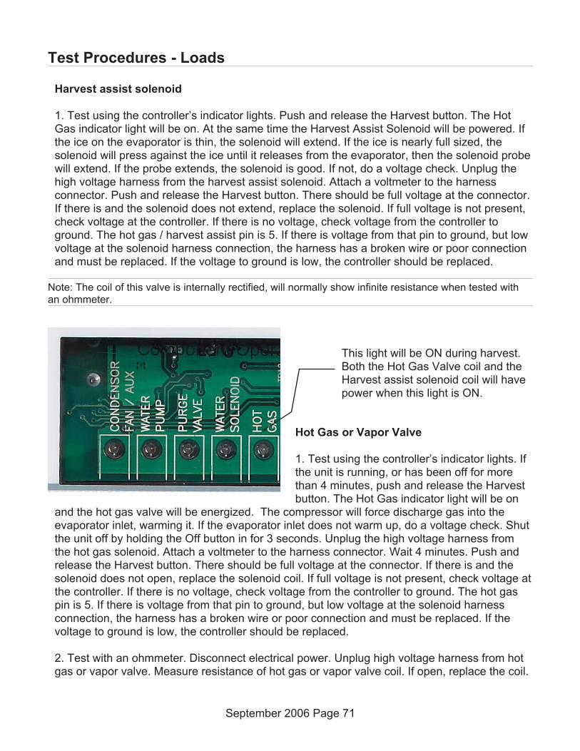
Harvest assist solenoid
1. Test using the controller’s indicator lights. Push and release the Harvest button. The HotGas indicator light will be on. At the same time the Harvest Assist Solenoid will be powered. Ifthe ice on the evaporator is thin, the solenoid will extend. If the ice is nearly full sized, thesolenoid will press against the ice until it releases from the evaporator, then the solenoid probewill extend. If the probe extends, the solenoid is good. If not, do a voltage check. Unplug thehigh voltage harness from the harvest assist solenoid. Attach a voltmeter to the harnessconnector. Push and release the Harvest button. There should be full voltage at the connector.If there is and the solenoid does not extend, replace the solenoid. If full voltage is not present,check voltage at the controller. If there is no voltage, check voltage from the controller toground. The hot gas / harvest assist pin is 5. If there is voltage from that pin to ground, but lowvoltage at the solenoid harness connection, the harness has a broken wire or poor connectionand must be replaced. If the voltage to ground is low, the controller should be replaced.
Note: The coil of this valve is internally rectified, will normally show infinite resistance when tested withan ohmmeter.
Hot Gas or Vapor Valve
1. Test using the controller’s indicator lights. Ifthe unit is running, or has been off for morethan 4 minutes, push and release the Harvestbutton. The Hot Gas indicator light will be on
and the hot gas valve will be energized. The compressor will force discharge gas into theevaporator inlet, warming it. If the evaporator inlet does not warm up, do a voltage check. Shutthe unit off by holding the Off button in for 3 seconds. Unplug the high voltage harness fromthe hot gas solenoid. Attach a voltmeter to the harness connector. Wait 4 minutes. Push andrelease the Harvest button. There should be full voltage at the connector. If there is and thesolenoid does not open, replace the solenoid coil. If full voltage is not present, check voltage atthe controller. If there is no voltage, check voltage from the controller to ground. The hot gaspin is 5. If there is voltage from that pin to ground, but low voltage at the solenoid harnessconnection, the harness has a broken wire or poor connection and must be replaced. If thevoltage to ground is low, the controller should be replaced.
2. Test with an ohmmeter. Disconnect electrical power. Unplug high voltage harness from hotgas or vapor valve. Measure resistance of hot gas or vapor valve coil. If open, replace the coil.
September 2006 Page 71
Test Procedures - Loads
This light will be ON during harvest.Both the Hot Gas Valve coil and theHarvest assist solenoid coil will havepower when this light is ON.
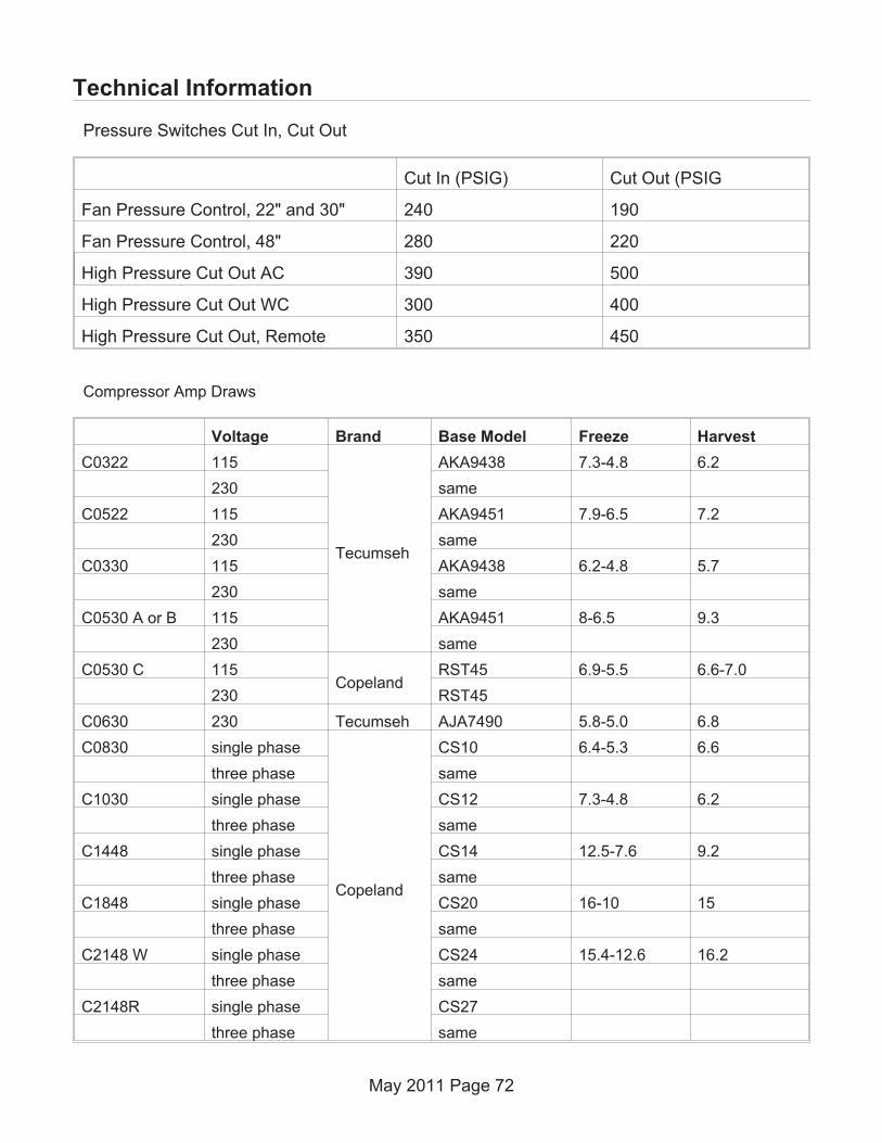
Technical Information
Pressure Switches Cut In, Cut Out
Cut In (PSIG) Cut Out (PSIG
Fan Pressure Control, 22" and 30" 240 190
Fan Pressure Control, 48" 280 220
High Pressure Cut Out AC 390 500
High Pressure Cut Out WC 300 400
High Pressure Cut Out, Remote 350 450
May 2011 Page 72
Compressor Amp Draws
Voltage Brand Base Model Freeze Harvest
C0322 115
Tecumseh
AKA9438 7.3-4.8 6.2
230 same
C0522 115 AKA9451 7.9-6.5 7.2
230 same
C0330 115 AKA9438 6.2-4.8 5.7
230 same
C0530 A or B 115 AKA9451 8-6.5 9.3
230 same
C0530 C 115Copeland
RST45 6.9-5.5 6.6-7.0
230 RST45
C0630 230 Tecumseh AJA7490 5.8-5.0 6.8
C0830 single phase
Copeland
CS10 6.4-5.3 6.6
three phase same
C1030 single phase CS12 7.3-4.8 6.2
three phase same
C1448 single phase CS14 12.5-7.6 9.2
three phase same
C1848 single phase CS20 16-10 15
three phase same
C2148 W single phase CS24 15.4-12.6 16.2
three phase same
C2148R single phase CS27
three phase same

Heat Load & Condenser Water GPM
Air Cooled - Average heat load for air conditioning unit sizing
Model BTUH
C0322 4000
C0522 6800
C0330 4000
C0530 6800
C0630 8800
C0803 10800
C1030 12000
C1448 17200
C1848 22000
Water Cooled Water Use - condenser only,
ModelGPM, 45
oF.
water inlettemp
GPM, 70oF. water
inlet temp
C0322 .2 .3
C0522 .3 .7
C0330 .1 .3
C0530 .3 .5
C0630 .4 .7
C0803 .4 .8
C1030 .4 1.0
C1448 .6 1.1
C1848 1.0 1.8
C2148 1.0 2.0
May 2008 Page 73

Controller Differences
The controllers are programmed at the factory for the model they are installed on, they cannotbe moved from one model to another due to differences in:
• Water purge time per setting
• Maximum harvest time
• Number of evaporator plates
The service controller has a selector switch that allows it to be used as a replacement part inany of the Prodigy models in production at the time the controller was manufactured. As newProdigy models are introduced, those models will be added to the list of models new servicecontrollers will work with.
September 2006 Page 74
The Service Controller includes a selector switch. The switch must be set to the model thecontroller is being installed on. As new models are introduced, their setting will be added to
service controllers produced after that point.

Thermistor Values
September 2006 Page 75
0. . . . . . 85325
1. . . . . . 82661
2. . . . . . 80090
3. . . . . . 77607
4. . . . . . 75210
5. . . . . . 72896
6. . . . . . 70660
7. . . . . . 68501
8. . . . . . 66415
9. . . . . . 64400
10. . . . . 62453
11. . . . . 60571
12. . . . . 58752
13. . . . . 56995
14. . . . . 55296
15. . . . . 53653
16. . . . . 52065
17. . . . . 50529
18. . . . . 49043
19. . . . . 47607
20. . . . . 46217
21. . . . . 44872
22. . . . . 43571
23. . . . . 42313
24. . . . . 41094
25. . . . . 39915
26. . . . . 38774
27. . . . . 37669
28. . . . . 36600
29. . . . . 35564
30. . . . . 34561
31. . . . . 33590
32. . . . . 32649
33. . . . . 31738
34. . . . . 30855
35. . . . . 30000
36. . . . . 29171
37. . . . . 28368
38. . . . . 27589
39. . . . . 26835
40. . . . . 26104
41. . . . . 25395
42. . . . . 24707
43. . . . . 24041
44. . . . . 23394
45. . . . . 22767
46. . . . . 22159
47. . . . . 21569
48. . . . . 20997
49. . . . . 20442
50. . . . . 19903
51. . . . . 19381
52. . . . . 18873
S3. . . . . 18381
54. . . . . 17903
55. . . . . 17439
56. . . . . 16988
57. . . . . 16551
58. . . . . 16126
59. . . . . 15714
60. . . . . 15313
61. . . . . 14924
62. . . . . 14546
63. . . . . 14179
64. . . . . 13823
65. . . . . 13476
66. . . . . 13139
67. . . . . 12812
68. . . . . 12494
69. . . . . 12185
70. . . . . 11884
71. . . . . 11592
72. . . . . 11308
73. . . . . 11031
74. . . . . 10763
75. . . . . 10502
76. . . . . 10247
77. . . . . 10000
78. . . . . 9760
79. . . . . 9526
80. . . . . 9299
81. . . . . 9077
82. . . . . 8862
83. . . . . 8652
84. . . . . 8448
85. . . . . 8250
86. . . . . 8056
87. . . . . 7868
88. . . . . 7685
89. . . . . 7507
90. . . . . 7333
91. . . . . 7164
92. . . . . 6999
93. . . . . 6839
94. . . . . 6683
95. . . . . 6530
96. . . . . 6382
97. . . . . 6238
98. . . . . 6097
99. . . . . 5960
100. . . . 5826
101. . . . 5696
102. . . . 5569
103. . . . 5446
104. . . . 5325
105. . . . 5208
106. . . . 5093
107. . . . 4981
108. . . . 4872
109. . . . 4766
110. . . . 4663
111. . . . 4562
112. . . . 4463
113. . . . 4367
114. . . . 4273
115. . . . 4182
116. . . . 4093
117. . . . 4006
118. . . . 3921
119. . . . 3838
120. . . . 3757
121. . . . 3678
122. . . . 3601
123. . . . 3526
124. . . . 3452
125. . . . 3381
126. . . . 3311
127. . . . 3243
128. . . . 3176
129. . . . 3111
130. . . . 3047
131. . . . 2985
132. . . . 2924
133. . . . 2865
134. . . . 2807
135. . . . 2751
136. . . . 2696
137. . . . 2642
138. . . . 2589
139. . . . 2537
140. . . . 2487
141. . . . 2438
142. . . . 2390
143. . . . 2343
144. . . . 2297
145. . . . 2252
146. . . . 2208
147. . . . 2165
148. . . . 2123
149. . . . 2082
150. . . . 2042
151. . . . 2003
152. . . . 1965
153. . . . 1927
154. . . . 1890
155. . . . 1855
156. . . . 1819
157. . . . 1785
158. . . . 1752
159. . . . 1719
160. . . . 1687
161. . . . 1655
162. . . . 1624
163. . . . 1594
164. . . . 1565
165. . . . 1536
166. . . . 1508
167. . . . 1480
168. . . . 1453.
169. . . . 1427
170. . . . 1401
171. . . . 1375
172. . . . 1350
173. . . . 1326
174. . . . 1302
175. . . . 1279
176. . . . 1256
177. . . . 1234
178. . . . 1212
179. . . . 1190
180. . . . 1169
181. . . . 1149
182. . . . 1129
183. . . . 1109
184. . . . 1090
185. . . . 1071
186. . . . 1052
187. . . . 1034
188. . . . 1016
189. . . . 998
190. . . . 981
191. . . . 965
192. . . . 948
193. . . . 932
194. . . . 916
195. . . . 901
196. . . . 885
197. . . . 871
198. . . . 856
199. . . . 842
200. . . . 828
201. . . . 814
202. . . . 800
203. . . . 787
204. . . . 774
205. . . . 761
206. . . . 749
207. . . . 737
208. . . . 724
209. . . . 713
210. . . . 701
211. . . . 690
212. . . . 679
213. . . . 668
214. . . . 657
215. . . . 646
216. . . . 636
217. . . . 626
218. . . . 616
219. . . . 606
220. . . . 597
221. . . . 587
222. . . . 578
223. . . . 569
224. . . . 560
225. . . . 551
226. . . . 543
227. . . . 534
228. . . . 526
229. . . . 518
230. . . . 510
231. . . . 502
232. . . . 495
233. . . . 487
234. . . . 480
235. . . . 472
236. . . . 465
237. . . . 458
238. . . . 451
239. . . . 444
240. . . . 438
241. . . . 431
242. . . . 425
243. . . . 419
244. . . . 412
245. . . . 406
246. . . . 400
247. . . . 394
246. . . . 389
249. . . . 383
250. . . . 377
Deg. F . . Ohms Deg. F . . Ohms Deg. F. . Ohms Deg. F. . Ohms Deg. F. . Ohms

Performance Data
C0322A
September 2006 Page 76
Ambient Air Temp., Degrees F.
70 80 90
Cycle Time(minutes)
Water Temp
50
70
80
90
10-12
11-12
12-13
13-14
12-13
13-14
14+
14-15
13-14
14-16
15-16
16-17
Suction Pressure(PSIG)
End of Freeze
Harvest
26
105
32
130
DischargePressure (PSIG)
End of Freeze
Harvest
235
150
250
200
C0322W
Ambient Air Temp., Degrees F.
70 80 90
Cycle Time(minutes)
Water Temp
50
70
80
90
9-11
11+
12+
12-13
11+
12+
13+
13-14
10-11
10-12
12-13
13+
Suction Pressure(PSIG)
End of Freeze
Harvest
32
95-100
32
100-110
DischargePressure (PSIG)
End of Freeze
Harvest
245
140
245
150
Ice per cycle weight: 2-4 to 2.6 lb.

Performance Data
C0522A
September 2006 Page 77
Ambient Air Temp., Degrees F.
70 80 90
Cycle Time(minutes)
Water Temp
50
70
80
90
11-13
13
14
15
13
14
15
16
16
16-18
18
19
Suction Pressure(PSIG)
End of Freeze
Harvest
32
105
34
120
DischargePressure (PSIG)
End of Freeze
Harvest
228
180
270
210
C0522W
Ambient Air Temp., Degrees F.
70 80 90
Cycle Time
(minutes)
Water Temp
50
70
80
90
13-15
15
16
16-17
15
16
17
17
14
14-15
15
16
Suction Pressure(PSIG)
End of Freeze
Harvest
23
85
36
110
DischargePressure (PSIG)
End of Freeze
Harvest
235
115
245
200
Ice per cycle weight: 4.5 to 5 lb.

Performance Data
C0330A
September 2006 Page 78
Ambient Air Temp., Degrees F.
70 80 90
Cycle Time(minutes)
Water Temp
50
70
80
90
9-10
10-11
11-12
12-13
10-11
11-12
12-13
13-14
11-12
12-13
13-14
14-15
Suction Pressure(PSIG)
End of Freeze
Harvest
28
110
DischargePressure (PSIG)
End of Freeze
Harvest
200
150
C0330W
Ambient Air Temp., Degrees F.
70 80 90
Cycle Time
(minutes)
Water Temp
50
70
80
90
8-10
10
11
11
10
11
11
11
10
10-11
11
12
Suction Pressure(PSIG)
End of Freeze
Harvest
33
95
35
110
DischargePressure (PSIG)
End of Freeze
Harvest
235
130
235
150
Ice per cycle weight: 2.4 to 2.6 lb
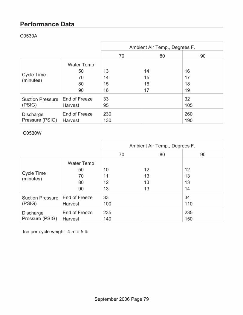
Performance Data
C0530A
September 2006 Page 79
Ambient Air Temp., Degrees F.
70 80 90
Cycle Time(minutes)
Water Temp
50
70
80
90
13
14
15
16
14
15
16
17
16
17
18
19
Suction Pressure(PSIG)
End of Freeze
Harvest
33
95
32
105
DischargePressure (PSIG)
End of Freeze
Harvest
230
130
260
190
C0530W
Ambient Air Temp., Degrees F.
70 80 90
Cycle Time(minutes)
Water Temp
50
70
80
90
10
11
12
13
12
13
13
13
12
13
13
14
Suction Pressure(PSIG)
End of Freeze
Harvest
33
100
34
110
DischargePressure (PSIG)
End of Freeze
Harvest
235
140
235
150
Ice per cycle weight: 4.5 to 5 lb

Performance Data
C0630A
September 2006 Page 80
Ambient Air Temp., Degrees F.
70 80 90
Cycle Time(minutes)
Water Temp
50
70
80
90
9-10
10-11
11-12
12-13
10-11
11-12
12-13
13-14
10-11
11-12
12-13
13-14
SuctionPressure (PSIG)
End of Freeze
Harvest
21
85
27
115
DischargePressure (PSIG)
End of Freeze
Harvest
200
160
255
200
C0630W
Ambient Air Temp., Degrees F.
70 80 90
Cycle Time(minutes)
Water Temp
50
70
80
90
9
10
11
11
10
11
11
11
10
11
12
13
SuctionPressure (PSIG)
End of Freeze
Harvest
25
75
22
80
DischargePressure (PSIG)
End of Freeze
Harvest
235
140
235
155
Ice per cycle weight: 4.5 to 5 lb

Performance Data
C0830A
September 2006 Page 81
Ambient Air Temp., Degrees F.
70 80 90
Cycle Time(minutes)
Water Temp
50
70
80
90
11
12
13
14
12
13
14
15
13
14
15
16
SuctionPressure (PSIG)
End of Freeze
Harvest
26
80
30
100
DischargePressure (PSIG)
End of Freeze
Harvest
204
160
260
195
C0830W
Ambient Air Temp., Degrees F.
70 80 90
Cycle Time(minutes)
Water Temp
50
70
80
90
11
12
13
14
12-13
13-14
13-14
14
13
13
14
15
SuctionPressure (PSIG)
End of Freeze
Harvest
30
85
31
90
DischargePressure (PSIG)
End of Freeze
Harvest
235
175
237
178
Ice per cycle weight: 7 - 7.3 lb

Performance Data
C1030A
September 2006 Page 82
Ambient Air Temp., Degrees F.
70 80 90
Cycle Time(minutes)
Water Temp
50
70
80
90
9-10
10-11
11-12
10-13
10-11
11-12
12-13
13-14
11-12
12-13
13
14-15
SuctionPressure (PSIG)
End of Freeze
Harvest
26
80
30
90
DischargePressure (PSIG)
End of Freeze
Harvest
210
165
260
190
C1030W
Ambient Air Temp., Degrees F.
70 80 90
Cycle Time(minutes)
Water Temp
50
70
80
90
10
11
11-12
12
11
11-12
12
12-13
11
11
12
13
SuctionPressure (PSIG)
End of Freeze
Harvest
26
70
30
75
DischargePressure (PSIG)
End of Freeze
Harvest
240
145
240
155
Ice per cycle weight: 7 - 7.3 lb

Performance Data
C1448A
September 2006 Page 83
Ambient Air Temp., Degrees F.
70 80 90
Cycle Time(minutes)
Water Temp
50
70
80
90
12-13
13-14
14-15
15-16
13-14
14-15
15-16
16-17
14-15
15-16
16-17
17-18
SuctionPressure (PSIG)
End of Freeze
Harvest
38
100
40
100
DischargePressure (PSIG)
End of Freeze
Harvest
250
150
270
160
C1448W
Ambient Air Temp., Degrees F.
70 80 90
Cycle Time(minutes)
Water Temp
50
70
80
90
13-14
14-15
15-16
15-16
14-15
15-16
15-16
15-16
15-16
15-16
16-17
17-18
SuctionPressure (PSIG)
End of Freeze
Harvest
36
105
35
100
DischargePressure (PSIG)
End of Freeze
Harvest
235
170
235
165

Performance Data
C1848A
September 2006 Page 84
Ambient Air Temp., Degrees F.
70 80 90
Cycle Time(minutes)
Water Temp
50
70
80
90
10-11
11-12
12-13
13-14
11-12
12-13
13-14
14-15
12-13
13-14
14-15
15-16
SuctionPressure (PSIG)
End of Freeze
Harvest
30
90
32
100
DischargePressure (PSIG)
End of Freeze
Harvest
227
170
285
195
C1848A
Ambient Air Temp., Degrees F.
70 80 90
Cycle Time(minutes)
50
70
80
90
10-11
11-12
12-13
12-13
11-12
12-13
12-13
12-13
11-12
11-12
12-13
13-14
SuctionPressure (PSIG)
End of Freeze
Harvest
30
80
30
85
DischargePressure (PSIG)
End of Freeze
Harvest
240
155
240
165
14 lb / cycle.

Performance Data
C2148W
September 2006 Page 85
Ambient Air Temp., Degrees F.
70 80 90
Cycle Time(minutes)
Water Temp
50
70
80
90
9-10
10-11
11-12
11-12
10-11
11-12
11-12
11-12
11
11
12
13
SuctionPressure (PSIG)
End of Freeze
Harvest
27
75
27
75
DischargePressure (PSIG)
End of Freeze
Harvest
235
160
240
160
Ice weight per cycle: 14.2

Performance Data - Remotes
C0522R
September 2006 Page 86
Condenser Intake Air Temp., Degrees F.
-20 70 80 90 120
Cycle Time(minutes)
Water Temp
50
70
80
90
10 12-13
13-14
14-15
15-16
13-14
13-14
14-15
17-18
14
14-15
15-16
18-19 23
Suction Pressure(PSIG)
End of Freeze
Harvest
35
85
35
90
DischargePressure (PSIG)
End of Freeze
HarvestMin 205
230
215
245
225
Peak at360
Ice per cycle, 4.4 to 4.6 lb

Performance Data - Remotes
C0530R
September 2006 Page 87
Condenser Intake Air Temp., Degrees F.
-20 70 80 90 120
Cycle Time(minutes)
Water Temp
50
70
80
90
10 11-13
14
15
16
13-14
14-15
15-16
17-18
13-14
14
15-16
17-18 27
Suction Pressure(PSIG)
End of Freeze
Harvest
30
145
35
100
DischargePressure (PSIG)
End of Freeze
Harvest207 min
230
200
245
220
Peaks at350

Performance Data - Remotes
C0630R
September 2006 Page 88
Condenser Intake Air Temp., Degrees F.
-20 70 80 90 120
Cycle Time(minutes)
Water Temp
50
70
80
90
7-8 9
9-10
10-11
12
9
9-10
11-12
14
9-10
10
11
13-14 16-17
SuctionPressure (PSIG)
End of Freeze
Harvest
30
110
30
120
DischargePressure (PSIG)
End of Freeze
HarvestMin 204
240
200
245
220
Peaks at370
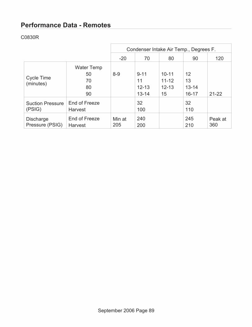
Performance Data - Remotes
C0830R
September 2006 Page 89
Condenser Intake Air Temp., Degrees F.
-20 70 80 90 120
Cycle Time(minutes)
Water Temp
50
70
80
90
8-9 9-11
11
12-13
13-14
10-11
11-12
12-13
15
12
13
13-14
16-17 21-22
Suction Pressure(PSIG)
End of Freeze
Harvest
32
100
32
110
DischargePressure (PSIG)
End of Freeze
Harvest
Min at205
240
200
245
210
Peak at360
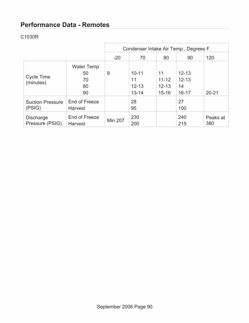
Performance Data - Remotes
C1030R
September 2006 Page 90
Condenser Intake Air Temp., Degrees F.
-20 70 80 90 120
Cycle Time(minutes)
Water Temp
50
70
80
90
9 10-11
11
12-13
13-14
11
11-12
12-13
15-16
12-13
12-13
14
16-17 20-21
Suction Pressure(PSIG)
End of Freeze
Harvest
28
95
27
100
DischargePressure (PSIG)
End of Freeze
HarvestMin 207
230
200
240
215
Peaks at380

Performance Data - Remotes
C1448R
September 2006 Page 91
Condenser Intake Air Temp., Degrees F.
-20 70 80 90 +120
Cycle Time(minutes)
Water Temp
50
70
80
90
9 11
11-12
13
14
11-12
11-12
13
15-16
14-15
14-15
16
18-19 22
Suction Pressure(PSIG)
End of Freeze
Harvest
40
100
40
125
DischargePressure (PSIG)
End of Freeze
HarvestMin 207
240
150
270
200
Peak at405
Ice per cycle, 12 lb.

Performance Data - Remotes
C1848R
August 2011 Page 92
Condenser Intake Air Temp., Degrees F.
-20 70 80 90 120
Cycle Time(minutes)
Water Temp
50
70
80
90
9 10-11
11-12
13
14
11-12
12
13-14
16
13
13
14-15
17 19
SuctionPressure (PSIG)
End of Freeze
Harvest
32
85
33
105
DischargePressure (PSIG)
End of Freeze
HarvestMin 210
240
170
245
205
Peak at370
Ice per cycle 14 lb.

Performance Data - Remotes
C2148R
September 2006 Page 93
Condenser Intake Air Temp., Degrees F
-20 70 80 90 120
Cycle Time(minutes)
Water Temp
50
70
80
90
9 10
9-10
11-12
12-13
10
10
11
14
11
12
13
15-16 18-19
Suction Pressure(PSIG)
End of Freeze
Harvest
24
80
24
95
DischargePressure (PSIG)
End of Freeze
HarvestMin 217
240
190
250
220
Peaks at410
Ice per cycle, 14-15 lb.

Wiring Diagrams
C0322, C0522, C0330, C0530, C0630, C0830, C1030 - Single Phase
September 2006 Page 94

Wiring Diagrams
C0530 C Air or Water Cooled 60 Hz
May 2011 Page 95

Wiring Diagram
C0830, C1030 - Three Phase
September 2006 Page 96

Wiring Diagram
C0522R, C0530R, C0630R, C0830R, C1030R - Single Phase
September 2006 Page 97

Wiring Diagrams
C0530R C
May 2011 Page 98
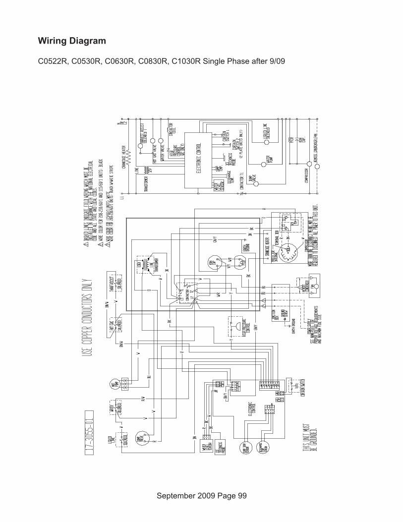
Wiring Diagram
C0522R, C0530R, C0630R, C0830R, C1030R Single Phase after 9/09
September 2009 Page 99

Wiring Diagram
C0522R, C0530R, C0630R, C0830R, C1030R - Three Phase
October 2006 Page 100

Wiring Diagram
C0522R, C0530R, C0630R, C0830R, C1030R Three Phase after 9/09
September 2009 Page 101

Wiring Diagram
C1448, C1848, C2148 Single Phase
September 2006 Page 102

Wiring Diagram
C1448, C1848, C2148 - three phase
March 2007 Page 103
17
-31
67
-01
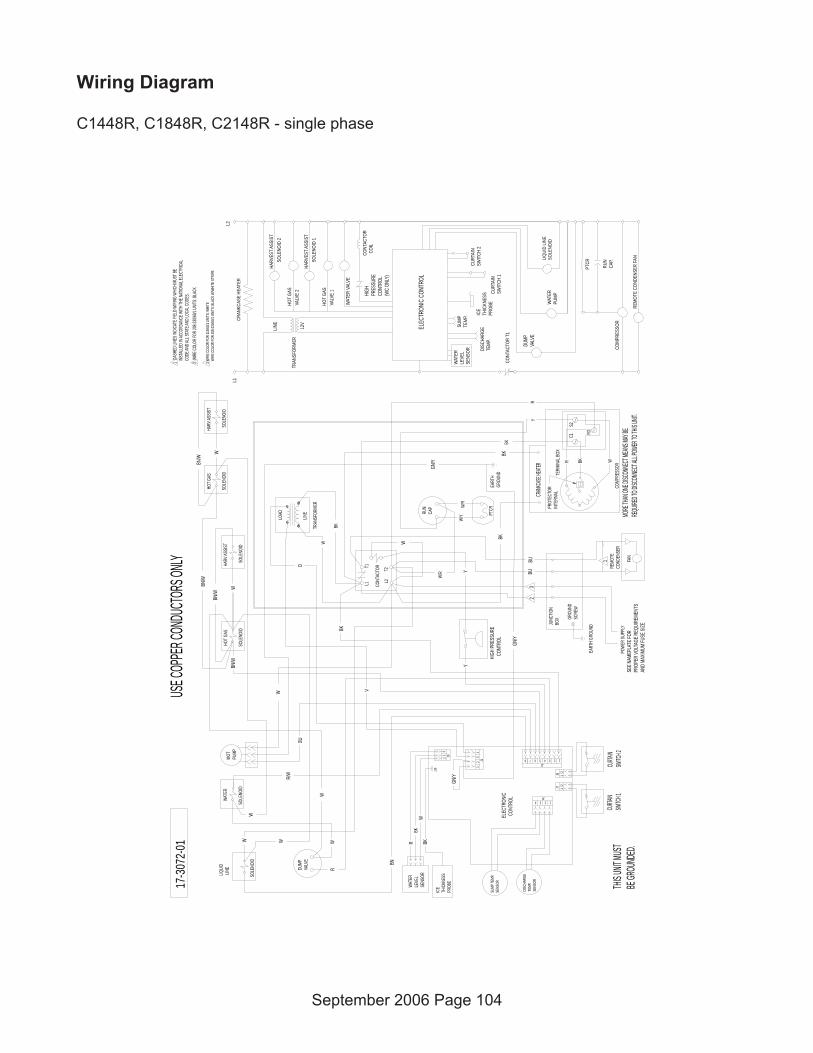
Wiring Diagram
C1448R, C1848R, C2148R - single phase
September 2006 Page 104
USE C
OPPE
R CON
DUCTO
RS ON
LY
THIS U
NIT MU
STBE
GROU
NDED
.
1 DA
SHED
LINE
S IND
ICATE
FIEL
D WIRI
NG W
HICH M
UST B
E I
NSTA
LLED
IN AC
CORD
ANCE
WITH
THE N
ATIO
NAL E
LECT
RICAL
COD
E AND
ALL S
TATE
AND L
OCAL
CODE
S.
MORE
THAN
ONE D
ISCON
NECT
MEAN
S MAY
BERE
QUIRE
D TO D
ISCON
NECT
ALL PO
WER T
O THIS
UNIT.
17-3
072-
012
WIRE
COLO
R FOR
208-2
30/60
/1 UN
ITS: B
LACK
W
BN/W
SOLE
NOID
2HA
RVES
T ASS
IST
VALV
E 1
HOT
GAS
SOLE
NOID
1HA
RVES
T ASS
IST
VALV
E 2
HOT
GAS
GN/Y
GN/Y
WSO
LENO
ID
LIQU
ID L
INE
GN/Y
CRAN
KCAS
E HEAT
ER
BKBK
CRAN
KCAS
E HE
ATER
W
BN/W
W
Y
W
ICE
THIC
KNES
SPR
OBE
CURT
AIN
SWIT
CH 1
CURT
AIN
SWIT
CH 2
J61234
W/Y
Y
HIGH
PRES
SURE
CONT
ROL
(WC
ONLY
)
L1T1
L2T2
CONT
ACTO
R
LINE
LOAD
TRAN
SFOR
MER
MOT
PUMP
SOLE
NOID
SOLE
NOID
HOT G
ASWA
TER
TERM
INAL
BOX
C1S2
R3
COMP
RESS
ORWBKR
RUN
CAP
PTCR
SEE N
AMEP
LATE
FOR
PROP
ER VO
LTAG
E REQ
UIRE
MENT
SAN
D MA
XIMUM
FUSE
SIZE
L1L2
LINE 12
VTR
ANSF
ORME
R
WAT
ER V
ALVE
CONT
ACTO
R C
OIL
COMP
RESS
OR
RUN
CAP.
WAT
ERPU
MP
PTCR
CONT
ACTO
R T1
WAT
ERLE
VEL
SENS
OR
SUMP
TEMP
.
DISC
HARG
ETE
MP.
ELEC
TRON
IC C
ONTR
OL
BU
W
BK
W
O
R/W
V
BN/W
ELEC
TRON
IC C
ONTR
OLBK
YR
W/R
W/R
W
DUMP
VALV
E
BK
DUMP
VALV
E
HIGH
PRES
SURE
CON
TROL
43
21
J1
32
1 J9
7 6 5 4 3 2 1J2
21J8
21J7
R
8
BN
DISC
HARG
ETE
MP.
SENS
OR
SUMP
TEMP
. SE
NSORWA
TER
LEVE
LSE
NSOR
WBK
R
EART
HGR
OUND
J10
HARV
ASSIS
T
SOLE
NOID
ICE
THIC
KNES
SPR
OBE
BK
W
JUNC
TION
BOX
EART
H GR
OUND
GROU
NDSC
REW
POWE
R SU
PPLY
LIQU
ID L
INE
SOLE
NOID
32
BUBU
REMO
TECO
NDEN
SER
FAN
1
3 WIR
E COL
OR FO
R 11
5/60/1
UNI
TS: W
HITE
WIR
E COL
OR FO
R 20
8-230
/60/1
UNITS
: BLA
CK W
/WHI
TE ST
RIPE
REMO
TE C
ONDE
NSER
FAN
WSO
LENO
ID
HARV
ASSIS
THO
T GAS
SOLE
NOID
BN/W
CURTA
INSW
ITCH 2
CURTA
INSW
ITCH 1
PROT
ECTO
RIN
TERN
AL

Wiring Diagram
C1448R, C1848R. C2148R - three phase
October 2006 Page 105

Wiring Diagram
C1448R-63 230/380-420/50/3
June 2008 Page 106

Repair Procedures
Inlet Water Solenoid Valve
1 Disconnect electrical power
2 Shut off the water supply.
3 Remove front and left side panels.
4 Unplug wire from coil.
5 Disconnect water supply tube from theinlet of the valve.
6 Disconnect the water outlet tube.
7 Remove the two mounting screws holding the valve to the back panel.
8 Pull the valve forward and out of the machine.
Fan Blade or Motor
1 Push and release the Off button
2 Disconnect electrical power.
3 Remove front panel, sound shield and left side panel.
4 Unplug fan motor wire leads.
5 Remove fan motor mounting brackets from shroud. Note: Fastener size is 3/8” hex
6 Carefully remove fan motor and blade assembly from machine cabinet.
7 Loosen set screw, pull fan blade from motor shaft.
8 If the blade is the only part being changed, reverse to reassemble. Note: blade mountspurge to end of motor shaft.
9 If the motor will be changed, remove mounting brackets from fan motor. Note: Fastenersize is ¼” hex.
10 Reverse to reassemble.
September 2006 Page 107
Electrical Shock Hazard.
Disconnect electricalpower before beginning.
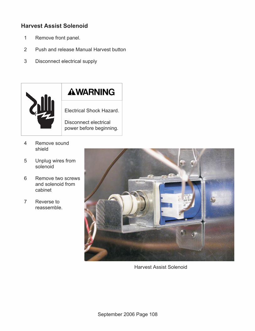
Harvest Assist Solenoid
1 Remove front panel.
2 Push and release Manual Harvest button
3 Disconnect electrical supply
4 Remove soundshield
5 Unplug wires fromsolenoid
6 Remove two screwsand solenoid fromcabinet
7 Reverse toreassemble.
September 2006 Page 108
Harvest Assist Solenoid
Electrical Shock Hazard.
Disconnect electricalpower before beginning.

Ice thickness sensor
1 Push and release the Off switch.
2 Remove front and top panels.
3 Push and release the Harvest switch
4 Remove the evaporator cover.
5 Remove the sound shield.
6 Disconnect electrical power.
7 Open the control box.
8 Remove curtain.
9 Locate sensor, squeeze mounting legs together to release it from the mounting bracket.
10 Remove sensor, follow wire back to control box.
11 Disconnect from controller connection J10.
12 Remove sensor from machine.
13 Reverse to reassemble.
14 Set initial probe-to-evaporator-surface gap using a 7/32” drill bit as a gauge.
September 2006 Page 109
Repair Procedures
Electrical Shock Hazard.
Disconnect electricalpower before beginning.

Capacitor (run)
1 Disconnect electrical power.
2 Remove front panel.
3 Open control box cover.
4 Remove right side of control box.
5 Remove metal barrier from control box
6 Remove screw holding strap to back of the control box.
7 Remove wires from capacitor
8 Connect wires to new capacitor, refer to wiring diagram as needed.
9 Reverse to reassemble.
Contactor
1 Disconnect electrical power.
2 Remove front panel.
3 Open control box cover.
4 Remove right side of controlbox.
5 Remove metal barrier fromcontrol box
6 Remove mounting screwsholding contactor to controlbox.
7 Exchange wires from oldcontroller to new. Refer to wiring diagram as needed.
8 Reverse to reassemble.
September 2006 Page 110
Repair Procedures
Electrical Shock Hazard.
Disconnect electricalpower before beginning.

Controller
1 Disconnect electrical power.
2 Remove front panel.
3 Open control box door.
4 Unplug all wires from controller.
5 Remove screws holding controller to door
6 Push controller snaps down and pullcontroller from mounting bracket.
7 Before touching new controller, dischargeany static electricity by touching the metalsurface of the ice machine cabinet.
8 Rotate selector switch to the proper modelnumber for the machine the controller isbeing installed on.
9 Install new controller on mounting bracket,secure with original screws.
10 Attach all wires removed.
11 Shut control box cover.
12 Switch on the electrical power.
September 2006 Page 111
Repair Procedures
Controller's Model Selector Switch
Electrical Shock Hazard.
Disconnect electricalpower before beginning.

Curtain
1 Push and hold the Off button to shut the machine off.
2 Remove front panel.
3 Remove evaporator cover.
4 Push inside tab in to release front curtain pin from holder.
5 Pull curtain from machine.
6 Reverse to reassemble.
7 Push and release the ON button to restart the machine.
Curtain switch
1 Push and hold the Off button to shut the machine off.
2 Disconnect electrical power
3 Remove front panel.
4 Remove evaporator cover.
5 Remove sound shield
6 Open control box.
7 Locate curtain switch on evaporator mounting bracket. Pull switch from its snaps.
8 Dismount wires from sump cover and remove from J7 or J8 connector on control board.
9 Reverse to reassemble. Be sure wires are re-mounted to sump cover edge.
September 2006 Page 112
Repair Procedures
Electrical Shock Hazard.
Disconnect electricalpower before beginning.

Purge valve
1 Push and hold the Off button to shut themachine off.
2 Disconnect electrical power.
3 Remove front panel.
4 Remove left side panel.
5 Unplug wires from valve coil.
Note: The coil can be removed from the valve body by rotating it 1/8 turnCW. After removal of the coil the spring and plunger can be taken out.
6 Remove screws holding valve to mounting bracket.
7 Remove inlet and outlet hoses
8 Remove valve from cabinet.
9 Reverse to reassemble
1 Push and release the On button to restart the machine
Water level sensor
1 Push and hold the Off button until the machine shuts off.
2 Remove the front panel.
3 Remove the sound shield.
4 Locate water level sensor.
5 Squeeze the locking tabs together and pull the sensor upand out of the sump.
6 Unplug the electrical connection from the sensor.
7 Reverse to reassemble.
September 2006 Page 113
Repair Procedures
Electrical Shock Hazard.
Disconnect electricalpower before beginning.

Water pump
1 Push and hold the Off button until themachine shuts off.
2 Remove the front panel.
3 Remove the sound shield.
4 Unplug the water pump
5 Rotate the pump CCW about 1/8 turn torelease it.
6 Lift pump up and remove hose
7 Attach hose to new pump
8 Install in pump bracket.
9 Rotate CW about 1/8 turn to lock it inplace.
10 Plug pump into harness
11 Return panels to their originalpositions and secure with the originalscrews.
12 Push and release the ON button torestart the machine.
September 2006 Page 114
Repair Procedures
Electrical Shock Hazard.
Disconnect electricalpower before beginning.
Refrigeration Removal and Replacement Procedures
Evaporator
1 Remove front panel.
2 Remove evaporator cover.
3 Remove right side panel.
4 Remove top panel.
5 If the machine was in operation, push and release the Harvest button to warm up theevaporator.
6 Disconnect electrical power.
7 Remove harvest assist solenoid
8 Recover refrigerant.
9 Remove curtain
10 Remove water distributor
11 Release ice thickness sensor
12 Remove water distributor bracket from the top of the evaporator
13 Connect nitrogen bottle to discharge access port. Open both access valves.
14 Open nitrogen valve
15 Unsweat the inlet and outlet refrigerant tubes. Use caution when heating the tubing, donot damage the freezing compartment walls.
16 Shut nitrogen valve.
September 2006 Page 115
Electrical Shock Hazard.
Disconnect electricalpower before beginning.

17 Gain access to the right side of the unit. Remove mounting screws holding the evaporatorto the freezing compartment wall. Note: fastener size is 5/16” hex.
18 Remove the evaporator from the ice machine.
19 Attach new evaporator to freezing compartment wall, but do not secure tightly at this time.
20 Install the harvest assist solenoid. Note location of ejector pin. Adjust position of theevaporator slightly to center the pin in the guide hole of the evaporator. When centered,tighten all evaporator fasteners.
21 Open nitrogen valve
22 Reconnect inlet and outlet tubes by brazing the copper tubes together.
23 Replace filter drier.
24 Shut access valves, remove nitrogen bottle.
25 Evacuate to at least 300 microns.
26 Weigh in the nameplate charge. Check for leaks.
27 Return ice thickness sensor bracket, ice thickness sensor, water distributor, curtain andevaporator cover to their original positions.
28 Reconnect electrical power.
29 Return sound shield and front panel to their original positions.
September 2006 Page 116
Refrigeration Removal and Replacement Procedures

Compressor
1 Remove front panel.
2 Remove sound shield
3 If the machine was in operation, push and release the Harvest button to shut it down.Wait until the harvest cycle has ended so the evaporator has no ice on it.
4 Open the replacement compressor box. Check the compressor nameplate, be SURE thatthe replacement compressor is the correct one for the unit.
5 Disconnect electrical power.
6 Recover refrigerant.
7 Remove compressor terminal cover and disconnect electrical leads.
8 Remove all the mounting bolts.
9 Open both discharge and suction access valves
10 Connect nitrogen to discharge access valve.
11 Open nitrogen valve.
12 Unsweat the suction, discharge and process tubes.
13 Unsweat the drier from the liquid line. Remove it.
14 Shut the nitrogen valve.
15 Remove the compressor from the ice machine. Note: Some models may require thecontrol box to be moved slightly to allow compressor replacement.
16 Immediately place new compressor in ice machine.
September 2006 Page 117
Refrigeration Removal and Replacement Procedures
Electrical Shock Hazard.
Disconnect electricalpower before beginning.

17 Open nitrogen bottle and braze compressor suction, discharge and process jointstogether. Braze new drier into system.
18 Shut off nitrogen, shut access valves.
19 Evacuate to at least 300 microns.
20 Replace PTCR and run capacitor.
21 Weigh in the nameplate charge. Check for leaks.
22 Reconnect electrical leads.
23 Attach compressor terminal cover.
24 Reconnect electrical power.
25 Return sound shield and front panel to their original positions.
Note: If the compressor is being returned for warranty, braze the stubs shut and tag the compressor withthe required information.
September 2006 Page 118
Refrigeration Removal and Replacement Procedures
Thermostatic Expansion Valve
1 Remove front panel.
2 Remove sound shield (when used)
3 If the machine was in operation, push and release the Harvest button to shut it down.Wait until the harvest cycle has ended so the evaporator has no ice on it.
4 Disconnect electrical power.
5 Recover refrigerant.
6 Remove insulation covering expansion valve and bulb.
7 Remove strap securing bulb to suction line.
8 Open both discharge and suction access valves
9 Unsweat the expansion valve from the liquid line. Remove it.
10 Unsweat the drier from the liquid line. Remove it.
11 Connect nitrogen to discharge access valve.
12 Immediately place new valve in ice machine.
13 Open nitrogen bottle and braze expansion valve inlet and outlet joints together. Brazenew drier into system.
14 Shut off nitrogen, shut access valves.
15 Evacuate to at least 300 microns.
16 Weigh in the nameplate charge. Check for leaks.
17 Attach bulb to suction line. Position at 4 or 8 o'clock on the tube. Secure tightly but do notcrush the bulb with the strap.
18 Attach valve and bulb insulation.
19 Reconnect electrical power.
20 Return sound shield and front panel to their original positions.
September 2006 Page 119
Refrigeration Removal and Replacement Procedures

Optional add-on control information
Vari-Smart™ Adjustable ice level option
The adjustable ice level control is an optional add-on system consisting of an control board,label and sensor.
The control board fits above the standard control and connects to it using connector J4. Thesensor mounts to the base of the ice machine through a hole in the base.
The control has an adjustment knob. Rotating the knob CW lowers the maximum ice level thatthe ice machine will maintain in the bin or dispenser. When the ice level is at or abovemaximum for the setting, the bin full light on the ultrasonic board will be ON.
September 2006 Page 120
Ultrasonic control shown in its installedposition, set at maximum fill.
Ultrasonic ice level control settings
0 = controlled by the curtain switch
1213
14
16
18
20
22
2426
11
10
9
0
32
30
28
Ultrasonic Board and Cable Back View of Ultrasonic Board

Adjustable Ice Level System Information and Diagnosis
The ultrasonic sensor in the base of the ice machine is located to take advantage of the naturalslope of the ice as it builds up in the bin. The numbers of the settings are from the sensor tothe top of the ice pile directly under the sensor.
If the Vari-Smart system fails to shut off the machine and ice overfills the bin or dispenser, thecurtain switch in the machine will switch the machine off, and will also restart the machinewhen ice is removed.
Note: Additional information on this option is included with the instructions provided with it.
September 2006 Page 121

Prodigy's Smart-Board™ - an Advanced Feature Control
An optional control is available that can provide users with more features. It is available eitheras a field installed option or as a data-logger that can be used by the service technician.
The kit number for the add on option is: KSBU
The kit number for the data logger version is: TPDL1 or TPDL2
The Smart-Board can be applied to most Prodigy models. It can be used:
• With the standard controller
• With the standard controller and the SmartLock device (KSL)
• With the standard controller and the Vari-Smart™ Ice Level Control (KVS)
• With the standard controller, and both the KSL and the KVS
Smart-Board abilities include:
• Ethernet connection
• USB connection to be used with Scotsman's Prodigy TechTool software
• Data Logging
• Data Display
The Smart-Board mounts to the controlbox door just below the main controller.The cable connecting the two routes fromthe main controller Accessory connector toJ1 of the Smart-Board.
If the datalogger version is used, it plugsinto the Accessory connector of the maincontroller.
If a SmartLock device is also connected,the SmartLock cable must be moved fromthe Accessory connector to the RLOconnector of the SmartBoard.
Features and use instructions are includedwith either the KSB or the TPDL1.
September 2006 Page 122
Back of Controller, with SmartBoard andVari-Smart Options installed.
Vari-Smart
Smart-Board
Smart-BoardCable Connects
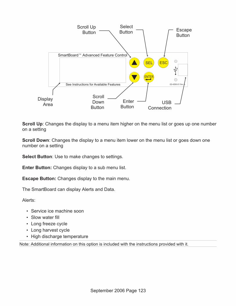
Scroll Up: Changes the display to a menu item higher on the menu list or goes up one numberon a setting
Scroll Down: Changes the display to a menu item lower on the menu list or goes down onenumber on a setting
Select Button: Use to make changes to settings.
Enter Button: Changes display to a sub menu list.
Escape Button: Changes display to the main menu.
The SmartBoard can display Alerts and Data.
Alerts:
• Service ice machine soon
• Slow water fill
• Long freeze cycle
• Long harvest cycle
• High discharge temperature
Note: Additional information on this option is included with the instructions provided with it.
September 2006 Page 123
SmartBoard Advanced Feature Control™
See Instructions for Available Features
34 SEL
02-4293-01 Rev A.
ENTER
ESC
Scroll UpButton
ScrollDown
Button
SelectButton
EnterButton
DisplayArea
EscapeButton
USBConnection

Remote SmartLock (KSL)
The remote lock out feature can be added to any controller. The feature allows someone,using a special paging service and code to control the on and off operation of that ice machine.
When a controller is locked out, the machine will finish a cycle and then stop. Switching thepower off and on, pushing any amount or combination of switches will not restart the machine.It can only restart when it receives a clear signal from the remote lockout board.
The remote lock out consists of an antenna and cable. The antenna must be mounted onto theback of the ice machine cabinet. Two holes are provided for mounting. The connecting cableroutes from the antenna through a hole in the back panel into the bottom of the control box.
Connect the antenna to the Accessory connector on the main board, or, if a SmartBoard hasbeen installed on the machine, onto the RLO connector of the SmartBoard.
Due to the sensitive nature of this option, further information will only be supplied to registeredusers of a SmartLock device.
September 2006 Page 124

Index
B
Bridge Thickness . . . . . . . . . . . . . 7
C
Clear diagnostic code: . . . . . . . . . . . 40
Code Display . . . . . . . . . . . . . . . . 22
Component Indicator Light Table . . . . . . 34
Component Indicator Lights . . . . . . . . 23
Compressor . . . . . . . . . . . . . . . . 32
Contactor . . . . . . . . . . . . . . . . . . 32
Controller Connections: . . . . . . . . . . 37
Controller . . . . . . . . . . . . . . . . . . 33
Curtain Switch(es) . . . . . . . . . . . . . 33
D
Discharge temperature sensor.. . . . . . . 34
E
Electrical Components: . . . . . . . . . . . 21
Electrical Sequence - Air or Water Cooled . 27
Electrical Sequence - Remote Cooled . . . 29
Empty reservoir. . . . . . . . . . . . . . . 40
F
Fan Motor(s) . . . . . . . . . . . . . . . . 32
H
Harvest Assist Solenoid(s) . . . . . . . . . 32
High pressure cut out. . . . . . . . . . . . 32
Hot Gas Valve(s) . . . . . . . . . . . . . . 33
I
Ice Thickness Sensor. . . . . . . . . . . . 33
Inlet Water Solenoid Valve . . . . . . . . . 32
L
Limitations . . . . . . . . . . . . . . . . . 4
Liquid Line Valve . . . . . . . . . . . . . . 33
Lock / Unlock control:. . . . . . . . . . . . 40
M
Max freeze time – 45 minutes . . . . . . . 38
Max harvest time – 3 minutes . . . . . . . 38
Min freeze time – 6 minutes . . . . . . . . 38
Model Number . . . . . . . . . . . . . . . 2
P
Plumbing Requirements . . . . . . . . . . 5
Power Interruption . . . . . . . . . . . . . 39
Purge Valve . . . . . . . . . . . . . . . . 32
R
Recall diagnostic code: . . . . . . . . . . . 40
Refrigerant . . . . . . . . . . . . . . . . . 63
Remote Condenser Location . . . . . . . . 13
Remote Systems . . . . . . . . . . . . . . 35
Reset control: . . . . . . . . . . . . . . . . 40
S
Set purge level, . . . . . . . . . . . . . . 40
Setting Codes . . . . . . . . . . . . . . . 22
Start Test Mode: . . . . . . . . . . . . . . 40
September 2006 Page 125

T
Test Mode Sequence - Remote . . . . . . 56
Test Mode: . . . . . . . . . . . . . . . . . 40
Transformer . . . . . . . . . . . . . . . . 33
W
Warranty . . . . . . . . . . . . . . . . . . 4
Water Filters . . . . . . . . . . . . . . . . 5
Water Interruption . . . . . . . . . . . . . 39
Water Level Sensor . . . . . . . . . . . . 33
Water Level Sensor: . . . . . . . . . . . . 36
Water Pump . . . . . . . . . . . . . . . . 32
Water Purge . . . . . . . . . . . . . . . . 3
Water purge setting. . . . . . . . . . . . . 8
Water temperature sensor. . . . . . . . . 33
September 2006 Page 126

Wiring Diagram
C0630R-6, C0830R-6, C1030R-6
September 2009

Wiring Diagram
C0530C 50 Hz
May 2011 Page 2

SCOTSMAN ICE SYSTEMS
775 Corporate Woods Parkway, Vernon Hills, IL 60061
800-533-6006
www.scotsman-ice.com
17-3141-01


