
Notice Inviting Tender (For Equipment to be procured under FIST-2014 scheme)
( e- proc/PEC/FIST-2014/EEE/2016/Power Electronics)
Pondicherry Engineering College
Department of EEE
www.pec.edu
(Contains 14 Pages Numbered Serially Excluding this cover Sheet)

1
e- proc/PEC/FIST-2014/EEE/2016/ Power Electronics Dated : 12-02-2013
NOTICE INVITING TENDER
1. ‘e’ -Tender form for the supply of items under FIST-2014 Scheme
1.1. e-Tender is invited by Principal, Pondicherry Engineering College (PEC) upto 03.00 P.M
on the due date from all intending tenderer(s) for the supply of items procured under
FIST-2014 scheme as per the specifications.
1.2. e-tenders should be addressed to The Principal, Pondicherry Engineering College,
Puducherry – 605 014.
1.3 The tender should be as per the BOQ form. Otherwise the tender will be rejected.
1.4 The tender shall be digitally signed.
1.5 Eligibility Conditions
The bidders are required to fulfill the following eligibility conditions and furnish scanned
documentary evidence listed below:-
1. Bidder should be a registered manufacturing company in India and existing for the past
three years.(Proof : Copy of Company Registration Certificate should be enclosed.)
2. The bidder / Principal must have supplied similar kind of equipment to atleast three State /
Central academic institutions/ research organizations during the past 3 - 5years. (Proof :
Copy of Supply orders should be enclosed.)
3. Bidder should have an Annual turnover of at least Rs.75 lakh in the previous three audited
financial years. (Proof : Copy of audited balance sheets should be enclosed)
4. The bidder must furnish the name of the persons and contact details of the customers to
whom the similar kind of equipment has been previously supplied.
5. The bidder must produce a certificate from the Principal that they are the authorized dealer /

2
agent to tender for the equipment.
6. Successful bidders must supply, install and demonstrate the equipment in the College
without any additional cost.
7. The bidder should have the facility to service the equipment after the warranty period and
should indicate the service centres available in South India.
1.6 Tender Fee & Earnest Money Deposit
The Tenderer must pay a Tender Fee of Rs. 525 (Inclusive of Taxes) and an Earnest
Money Deposit (EMD) for a sum Rs. 18,000 /-(Rupees Eighteen thousand only).The
EMD and Tender Fee is payable to The Principal, Pondicherry Engineering College
through Canara Bank SB A/c No. 8441101050701, IFSC Code: CNRB 0008441, MICR
Code: 605055004. The payment of EMD and Tender Fee should be done through
internet banking/online mode only. Demand Draft will not be accepted. The bidders
can make online payment through any of the 32 banks listed in the Annexure to
this NIT.
1.7. Validity of the tender
Tenders should be valid for acceptance for a period of at least 60 (Sixty) days from the
date of opening.
1.8. Guarantee
The materials/equipment shall be guaranteed for satisfactory performance/working for a
period of atleast twelve months (12) from the date of commissioning. Any defects
notified during this period shall be rectified free of charge to the satisfaction of the
College / Department.
1.9 Leaflets and Description Literature
Full descriptive particulars, Technical Specifications, Make and Model should
accompany the tender as scanned copy of brochures / pamphlets of the equipment
offered.

3
1.10. Tender Opening
e-Tenders will be opened by The Principal, PEC, or his representative at 3.30 PM on due
date. If the due date happens to a holiday, then , it will be opened on the subsequent
working day.
1.11. The Principal, PEC, Puducherry, reserves the right to reject any or all tenders, and
increase or decrease the quantity while ordering.
2. RATE AND CONDITIONS
2.1 Rates
The lowest rates quoted by the Tenderer should be firm, in rupees for free delivery at
the destination of this Institute and should include applicable Customs, Import, Excise
Duties, and Insurance and freight charges. The College will not pay separately for
transit insurance.
2.2. Delivery
The period of delivery should be 30 days from the receipt of supply order. Ex-
stock, quick and short delivery will be normally given preference. Delivery for the part
supply/supplies and the period required to complete the order in full should also be
specified. The delivery period should be kept up and no excuse such as lack of booking
facilities etc., will be accepted. In case goods booking cannot ensure delivery within the
scheduled period, booking should be done by lorry or other mode of road transport
without extra cost to the College and it is always the Supplier’s responsibility to arrange
for the transport. Any delay will be viewed seriously and suitable liquidated damages
will be imposed if necessary. The Tenderer should take these into consideration when
quoting. The Tenderer should clearly state when the supply would commence. The
delivery period specified in the tender should be clear and the specific terms should be
guaranteed by the Tenderer under our liquidated damages clause given as follows:
a. Should delivery be delayed by strike / lockouts, fire accidents or any causes what so

4
ever beyond the reasonable control of the Tenderer and whether such delay or
impediment occur before or after the time or extended time for dispatch or completion, a
reasonable extension of time shall be granted.
b. If supplies to be tendered are made by the Tenderer beyond the delivery period
stipulated and if they are accepted by the College, such acceptances are without
prejudice to rights of the College to levy liquidated damages for the delay in supply
governed by liquidated damages clauses.
c. The delivery should be made Free at Pondicherry Engineering College,
Puducherry.
2.3 Extension of Delivery period:
No extension of time beyond that delivery period quoted will normally be granted.
2.3 Payment:
100% will be made within 30 days on receipt and successful installation & testing of
equipment, acceptance by the department and receipt of bills in triplicate along with
advance stamped receipt for the amount. All payments will be made only after the
approval of quality of materials.

5
3. SPECIFICATIONS
Power Electronics
Sl.No Equipment & Specification Qty.
1 1KW solar PV standalone Generation system:
The setup should consists of 4 nos. 250watts polycrystalline solar panels.
MPPT charge controller, IGBT based 1 phase inverter. 4 nos. of 12V
/120AH Batteries. Necessary frames and cabling. The unit should be
installed in the department and training has to be given.
1 No.
2 Single Phase converter firing circuit:
Four synchronized and isolated triggering pulses to fire thyristors connected
in single phase half wave, full wave, half controlled bridge and AC phase
control power circuit. Analog firing circuit based on ZCD, Ramp generator,
Op amp comparator and amplifier/pulse transformer isolation method.
Enclosed in powder coated MS box with Screen printed polycarbonate
panel.
Input: 230V AC mains. Firing angle variation from 180*- 0* on a graduated
scale. Test points to study the logic circuit.
4 Nos.
3 Single Phase converter firing circuit (Microcontroller based):
Micro controller based firing circuit with LCD display to indicate the firing
angle. Accuracy - +/- 1*.This unit generates four synchronized and isolated
triggering pulses to fire thyristors connected in single phase half wave, full
wave, half controlled bridge and AC phase control power circuit. Enclosed
in powder coated MS box with Screen printed polycarbonate panel.
Input: 230V AC mains. Firing angle variation from 180*- 0* on a graduated
scale. Test points to study the logic circuit.
2 Nos.
4 DC Chopper firing Circuit:
Firing pulses to trigger two SCRs connected in auxiliary commutated
chopper consists of one Main thyristor and an auxiliary thyristor. Analog
based circuit with amplifier/pulse transformer isolation. This unit should
also be useful for triggering other chopper circuits. Enclosed in powder
coated MS box with Screen printed polycarbonate panel.
4 Nos.

6
Input: 230V AC mains. Frequency variation from 30 – 300Hz. Duty cycle
variation from 10 to 90%. Test points to study the logic circuit.
5 DC Chopper firing Circuit (Microcontroller based)
Micro controller based firing circuit with LCD display to indicate the
frequency and duty cycle. Accuracy +/-1 Hz/% and +/-1 %.
Firing pulses to trigger two SCRs connected in auxiliary commutated
chopper consists of one Main thyristor and an auxiliary thyristor. Analog
based circuit with amplifier/pulse transformer isolation. This unit should
also be useful for triggering other chopper circuits. Enclosed in powder
coated MS box with Screen printed polycarbonate panel.
Input: 230V AC mains. Frequency variation from 30 – 300Hz. Duty cycle
variation from 10 to 90%. Test points to study the logic circuit.
2 Nos.
6 Single Phase Half & Fully controlled Converter power circuit -
230V/5A:
This unit should consists of 2 SCR’s / 4SCR’s and 2 power diodes to be
connected as half / fully controlled bridge. A freewheeling diode is to be
provided. Mounted on a suitable heat sink and protected by snubber circuit
and fuse. A circuit breaker is to be provided to switch ON/OFF the AC
supply to the power circuit and for protection. Voltmeter and Ammeter are
to be included to indicate output voltage and current. A separate bridge
rectifier for field supply of DC motor. All the connections are to be brought
out to front panel. This unit has to support R, RL, Lamp load and motor
load. Enclosure in powder coated MS box with Screen printed
polycarbonate panel.
Specification:- 230V/5A.
4 Nos.

7
7 A) Three Phase Half & Fully controlled Converter power circuit -
415V/5A:
This unit should consist of 3 SCR’s / 6SCR’s and 3 Power diodes to be
connected as half /fully controlled bridge. A freewheeling diode is also
provided. Each device is to be mounted on suitable heat sink and protected
by snubber circuit and fuse. A circuit breaker is provided to switch
ON/OFF the 3 phase supply to the power circuit and for protection.
Voltmeter and Ammeter are to be provided to indicate output voltage and
current. This unit can be used for R,R-L and motor load. Enclosed in
powder coated MS box with Screen printed polycarbonate panel.
Specification: 415V/ 5A.
B) THREE PHASE CONVERTER FIRING UNIT
(MICROCONTROLLER BASED) :
Micro controller based firing circuit with LCD display to indicate the
firing angle. Accuracy - +/- 1*.This unit generates six synchronized and
isolated triggering pulses to fire thyristors connected in 3 phase half and
fully controlled bridge converter and AC phase control power circuit.
Enclosed in powder coated MS box with Screen printed polycarbonate
panel.
Input: 230V AC mains. 3 phase ac mains supply for synchronization.
Firing angle variation from 180*- 0* on a graduated scale. Test points to
study the logic circuit.
4 Nos.
8 Series Inverter - 30V/2A
This unit should consist of 2SCRs, 2 diodes and LC commutation
components interconnected to form modified series inverter. All the devices
are mounted on a suitable heat sink and protected by snubber circuit and
fuse. All the connections are brought out to the front panel. Firing circuit to
vary the frequency from 100Hz to 500Hz.
Specification: 30V/2A
2 Nos.

8
9 Parallel Inverter - 30V/2A
This unit should have 2/42/ SCRs, 4 diodes, LC Commutation components
and a center tap transformer type parallel/parallel bridge inverter. All the
device are mounted on a suitable heat sink and protected by snubber circuit.
All the connections are brought out to the front panel. Firing circuit to vary
the frequency from 25Hz to 250Hz.
Specification: 30V / 2A
2Nos.
10 Single Phase PWM inverter - 230V/5A:
This unit should consists of 2 IGBT power modules (each module consists
of 2 IGBTs with built in diodes) of rating 5A /230 V. The modules are
mounted on proper heat sink and protected by snubber circuit and fuse. In
the input side MCB and fuse are provided for AC input – 0-230V. Input
AC supply is converted to DC supply using Single phase diode bridge
rectifier and filtered using capacitor and fed to Bridge inverter power
circuit. Analog Voltmeter and Analog Ammeter is provided to measure
DC bus voltage and current. Current shunt to observe current waveform.
1 No.

9
11 DC Chopper Power Circuit - 30V/2A
This unit should consists of 2 SCR’s, 2 Diodes, Commutation capacitor and
a tightly coupled center tapped Inductance. All the devices are to be
mounted on a suitable heat sink and protected by snubber circuit, fuse. All
the connections are brought out to front panel. Different chopper
configurations including JONES CHOPPER can be formed by different
inter connections. A separate bridge rectifier is provided for field supply of
DC motor. A DC circuit breaker is provided in series with the input
terminals for 220V input model. This unit can be used for R, R-L and
motor load. Enclosed in powder coated MS box with Screen printed
polycarbonate panel.
Specification: - 30V,2A
4Nos
12 Forced Commutation Study unit:
This unit should have of 2 SCR’s, a Diode, a Transistor and different values
of LC commutation components. These components need to be
interconnected to build power circuits to study Class A,B,C,D and E
commutation. Firing circuit to vary the frequency and duty cycle. A DC
power supply of 24V@1A is also provided for DC source. Enclosed in
powder coated MS box with Screen printed polycarbonate panel.
2Nos
13 Single-phase multi-function meter
Specification
10 Parameters on 10 Display Pages
Measures V, A, PF, Hz, KW, KVA, KVAr, KWh, KVAh&KVArh
Auto / Manual Scroll Display (User Selectable)
Reduces Panel Space and Wiring Time
State of The Art Microcontroller Design
TRMS Measurement
Ideal for Testing of Electrical Appliances
User Programmable CT Ratio (1.00 - 99.99)
LCD Display with Backlight (20mm Digit Height)
03
Nos.
10
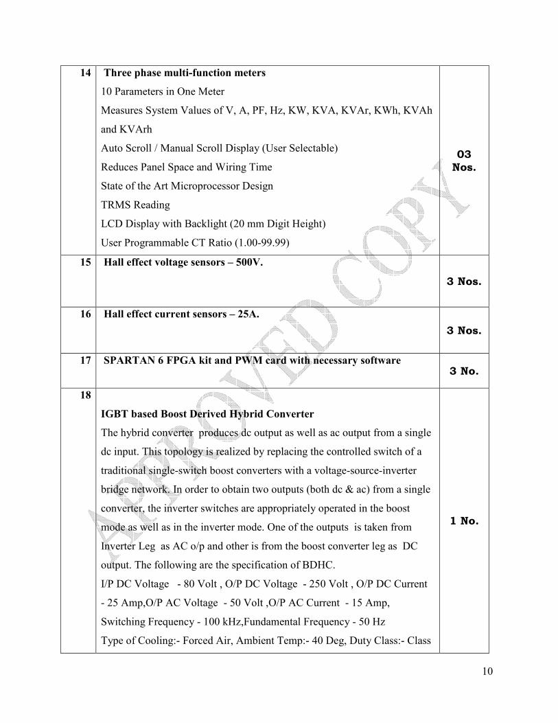
14 Three phase multi-function meters
10 Parameters in One Meter
Measures System Values of V, A, PF, Hz, KW, KVA, KVAr, KWh, KVAh
and KVArh
Auto Scroll / Manual Scroll Display (User Selectable)
Reduces Panel Space and Wiring Time
State of the Art Microprocessor Design
TRMS Reading
LCD Display with Backlight (20 mm Digit Height)
User Programmable CT Ratio (1.00-99.99)
03
Nos.
15 Hall effect voltage sensors – 500V.
3 Nos.
16 Hall effect current sensors – 25A.
3 Nos.
17 SPARTAN 6 FPGA kit and PWM card with necessary software 3 No.
18
IGBT based Boost Derived Hybrid Converter
The hybrid converter produces dc output as well as ac output from a single
dc input. This topology is realized by replacing the controlled switch of a
traditional single-switch boost converters with a voltage-source-inverter
bridge network. In order to obtain two outputs (both dc & ac) from a single
converter, the inverter switches are appropriately operated in the boost
mode as well as in the inverter mode. One of the outputs is taken from
Inverter Leg as AC o/p and other is from the boost converter leg as DC
output. The following are the specification of BDHC.
I/P DC Voltage - 80 Volt , O/P DC Voltage - 250 Volt , O/P DC Current
- 25 Amp,O/P AC Voltage - 50 Volt ,O/P AC Current - 15 Amp,
Switching Frequency - 100 kHz,Fundamental Frequency - 50 Hz
Type of Cooling:- Forced Air, Ambient Temp:- 40 Deg, Duty Class:- Class
1 No.
11
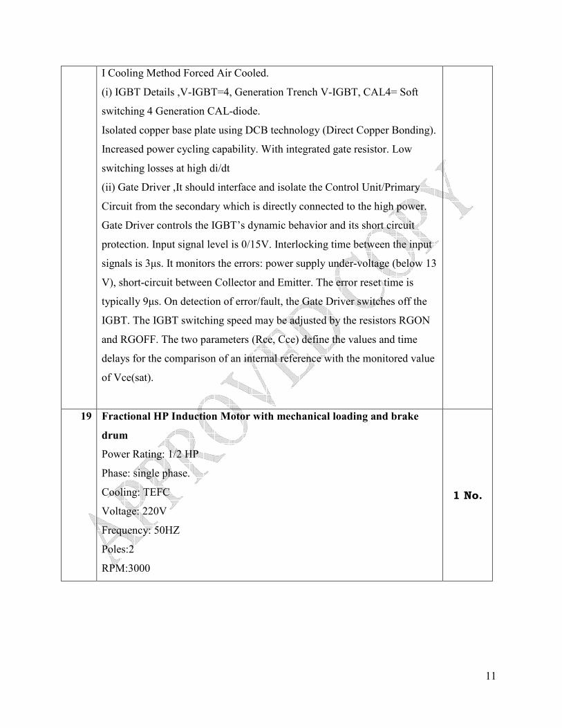
I Cooling Method Forced Air Cooled.
(i) IGBT Details ,V-IGBT=4, Generation Trench V-IGBT, CAL4= Soft
switching 4 Generation CAL-diode.
Isolated copper base plate using DCB technology (Direct Copper Bonding).
Increased power cycling capability. With integrated gate resistor. Low
switching losses at high di/dt
(ii) Gate Driver ,It should interface and isolate the Control Unit/Primary
Circuit from the secondary which is directly connected to the high power.
Gate Driver controls the IGBT’s dynamic behavior and its short circuit
protection. Input signal level is 0/15V. Interlocking time between the input
signals is 3µs. It monitors the errors: power supply under-voltage (below 13
V), short-circuit between Collector and Emitter. The error reset time is
typically 9µs. On detection of error/fault, the Gate Driver switches off the
IGBT. The IGBT switching speed may be adjusted by the resistors RGON
and RGOFF. The two parameters (Rce, Cce) define the values and time
delays for the comparison of an internal reference with the monitored value
of Vce(sat).
19 Fractional HP Induction Motor with mechanical loading and brake
drum
Power Rating: 1/2 HP
Phase: single phase.
Cooling: TEFC
Voltage: 220V
Frequency: 50HZ
Poles:2
RPM:3000
1 No.

12
20 Multiple Power Supply:
30V-2A, 0 to +/- 15V-1A, 5V-5A Multiple Power Supply
DC 0 to 30V/2A ,0 to +/-15V /1A Tracking, 4.5 to 5.5 /5A
Digital Display for voltage and current
Protection against overload and short circuit
Adjustable current limiter
Constant current & constant voltage
5 Nos.
PRINCIPAL / PEC

13
ANNEXURE
.
List of Banks for making on-line payment for e-tendering.
1. State Bank of India
2. State Bank of Bikaner & Jaipur
3. State Bank of Hyderabad
4. State Bank of Mysore
5. State Bank of Patiala
6. State Bank of Travancore
7. Bank of Maharashtra
8. Corporation Bank
9. Dena Bank
10. Indian Bank
11. Oriental Bank of Commerce
12. United Bank of India
13. Vijaya Bank
14. City Union Bank
15. Catholic Syrian Bank
16. Federal Bank
17. INGVysya Bank
18. Jammu & Kashmir Bank
19. KarurVysya Bank
20. South Indian Bank
21. Tamilnadu Mercantile Bank
22. DCB Bank
23. Lakshmi Vilas Bank
24. Punjab & Sind Bank
25. IDBI Bank
26. Indusind Bank
27. Syndicate Bank

14
28. UCO Bank
29. Andhra Bank
30. Bank of India
32. Dhanalakshmi Bank
The bidders may ensure that they hold account in any of the above listed banks and get Internet
Banking Facility for making payment online. The Bidders are advised to check whether
internet banking is working properly with the Username/Password which is provided by the
bank in which they hold account. It is advised not to test payment during Bid Submission in
the eProcurement Portal, since eProcurement Portal restricts online payment attempts not more
than 5 times. The bidders cannot make bid submission if they exceed the attempts.
The refund of EMD to unsuccessful bidders will be done automatically online. For any
clarifications contact e-Payment help desk: 022-27523796 (SBIePay, Mumbai).
PRINCIPAL / PEC
// APPROVED COPY //


