

© 2013 Cisco and/or its affiliates. All rights reserved. BRKCRS-2663 Cisco Public
Next Generation Campus Architectures BRKCRS-2663
2
© 2013 Cisco and/or its affiliates. All rights reserved. BRKCRS-2663 Cisco Public 3
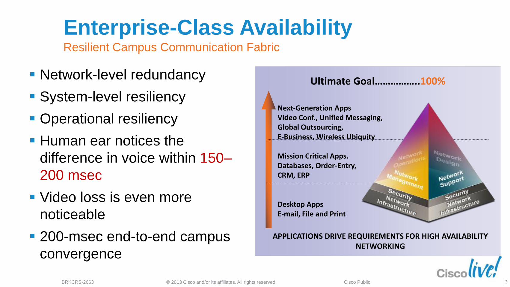
Enterprise-Class Availability Resilient Campus Communication Fabric
Network-level redundancy
System-level resiliency
Operational resiliency
Human ear notices the
difference in voice within 150–
200 msec
Video loss is even more
noticeable
200-msec end-to-end campus
convergence
Next-Generation Apps Video Conf., Unified Messaging, Global Outsourcing, E-Business, Wireless Ubiquity
Mission Critical Apps. Databases, Order-Entry, CRM, ERP
Desktop Apps E-mail, File and Print
Ultimate Goal……………..100%
APPLICATIONS DRIVE REQUIREMENTS FOR HIGH AVAILABILITY NETWORKING

© 2013 Cisco and/or its affiliates. All rights reserved. BRKCRS-2663 Cisco Public 4
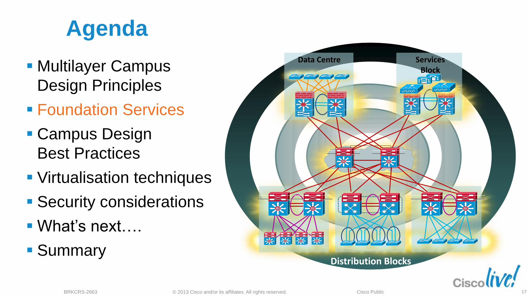
Agenda
SiSiSiSi
SiSiSiSi
SiSi
Data Centre
SiSi SiSi
Services Block
Distribution Blocks
SiSi SiSi SiSi
Multilayer Campus
Design Principles
Foundation Services
Campus Design
Best Practices
Virtualisation techniques
Security considerations
What’s next….
Summary

© 2013 Cisco and/or its affiliates. All rights reserved. BRKCRS-2663 Cisco Public 5
Access
Core
Distribution
Distribution
Access Data Centre WAN Internet
SiSi SiSi SiSi SiSi SiSi SiSi
SiSi SiSi
SiSi SiSi
SiSi SiSiSiSi
SiSi
High-Availability Campus Design Structure, Modularity, and Hierarchy

© 2013 Cisco and/or its affiliates. All rights reserved. BRKCRS-2663 Cisco Public 6
SiSi SiSi
SiSiSiSi
SiSi SiSi
Hierarchical Network Design Without a Rock Solid Foundation the Rest Doesn’t Matter
Building Block
Access
Distribution
Core
Distribution
Access Offers hierarchy - each layer has specific role
Modular topology - building blocks
Easy to grow, understand, and troubleshoot
Creates small fault domains - clear demarcations and isolation
Promotes load balancing and redundancy
Promotes deterministic traffic patterns
Incorporates balance of both Layer 2 and Layer 3 technology, leveraging the strength of both
Utilises Layer 3 routing for load balancing, fast convergence, scalability, and control

© 2013 Cisco and/or its affiliates. All rights reserved. BRKCRS-2663 Cisco Public 7
Server Farm
WAN Internet PSTN
SiSi
SiSi
SiSi SiSi
SiSi SiSi SiSi
SiSi
SiSi SiSi SiSi
SiSi
Not This!!
Hierarchical Campus Network Structure, modularity and hierarchy
© 2013 Cisco and/or its affiliates. All rights reserved. BRKCRS-2663 Cisco Public 8
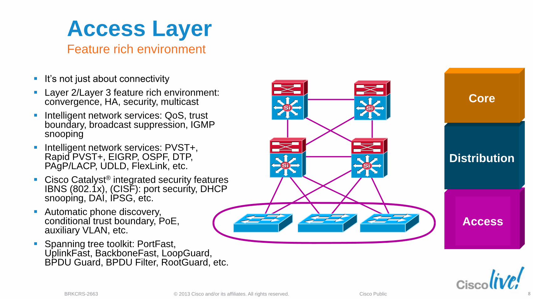
Access Layer Feature rich environment
It’s not just about connectivity
Layer 2/Layer 3 feature rich environment: convergence, HA, security, multicast
Intelligent network services: QoS, trust boundary, broadcast suppression, IGMP snooping
Intelligent network services: PVST+, Rapid PVST+, EIGRP, OSPF, DTP, PAgP/LACP, UDLD, FlexLink, etc.
Cisco Catalyst® integrated security features IBNS (802.1x), (CISF): port security, DHCP snooping, DAI, IPSG, etc.
Automatic phone discovery, conditional trust boundary, PoE, auxiliary VLAN, etc.
Spanning tree toolkit: PortFast, UplinkFast, BackboneFast, LoopGuard, BPDU Guard, BPDU Filter, RootGuard, etc.
Access
Distribution
Core SiSiSiSi
SiSi SiSi
© 2013 Cisco and/or its affiliates. All rights reserved. BRKCRS-2663 Cisco Public 9
SiSiSiSi
SiSi SiSi
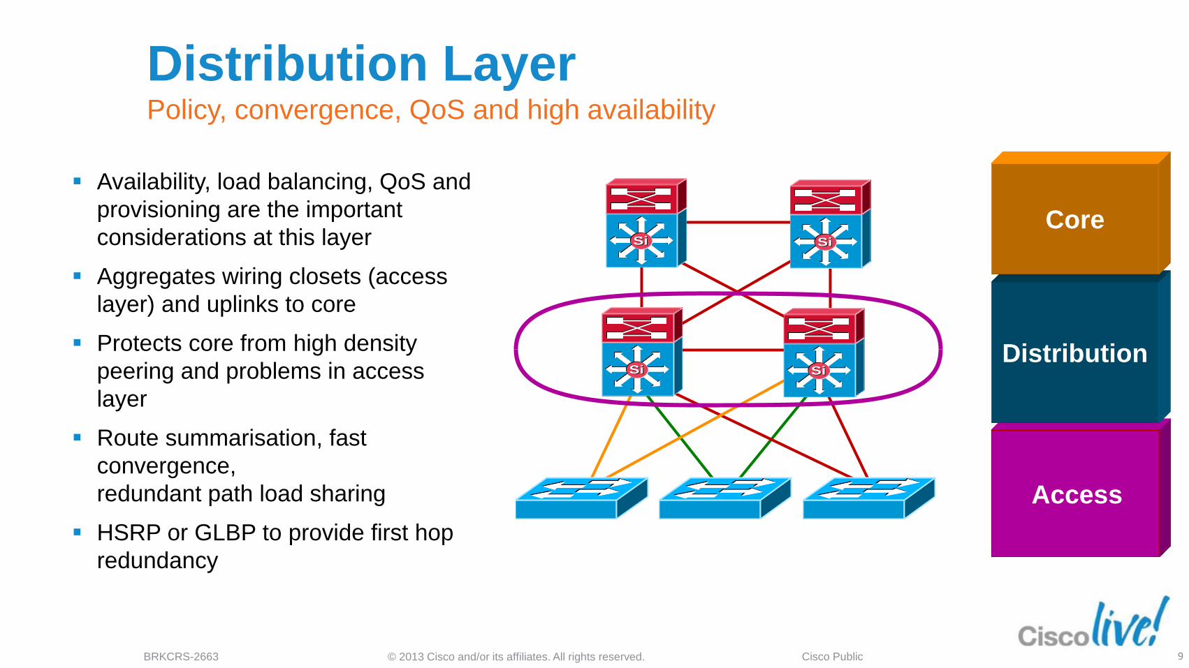
Distribution Layer Policy, convergence, QoS and high availability
Availability, load balancing, QoS and
provisioning are the important
considerations at this layer
Aggregates wiring closets (access
layer) and uplinks to core
Protects core from high density
peering and problems in access
layer
Route summarisation, fast
convergence,
redundant path load sharing
HSRP or GLBP to provide first hop
redundancy
Access
Distribution
Core
© 2013 Cisco and/or its affiliates. All rights reserved. BRKCRS-2663 Cisco Public 10
SiSiSiSi
SiSi SiSi
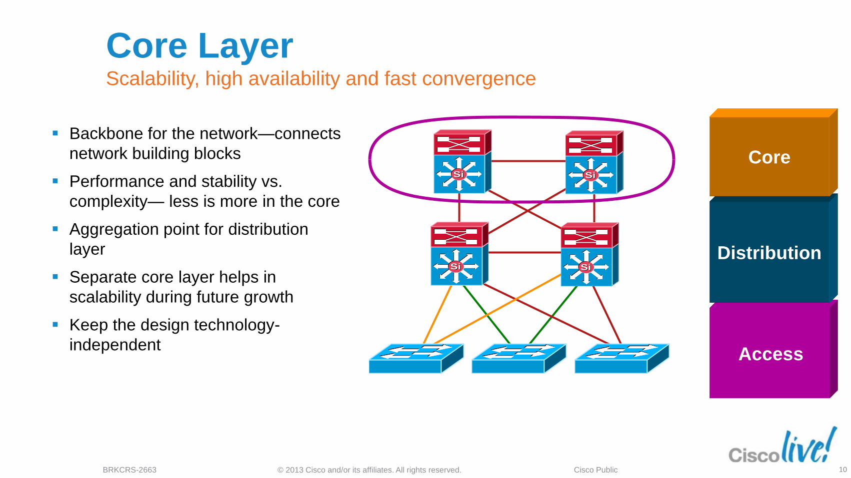
Core Layer Scalability, high availability and fast convergence
Backbone for the network—connects
network building blocks
Performance and stability vs.
complexity— less is more in the core
Aggregation point for distribution
layer
Separate core layer helps in
scalability during future growth
Keep the design technology-
independent Access
Distribution
Core
© 2013 Cisco and/or its affiliates. All rights reserved. BRKCRS-2663 Cisco Public
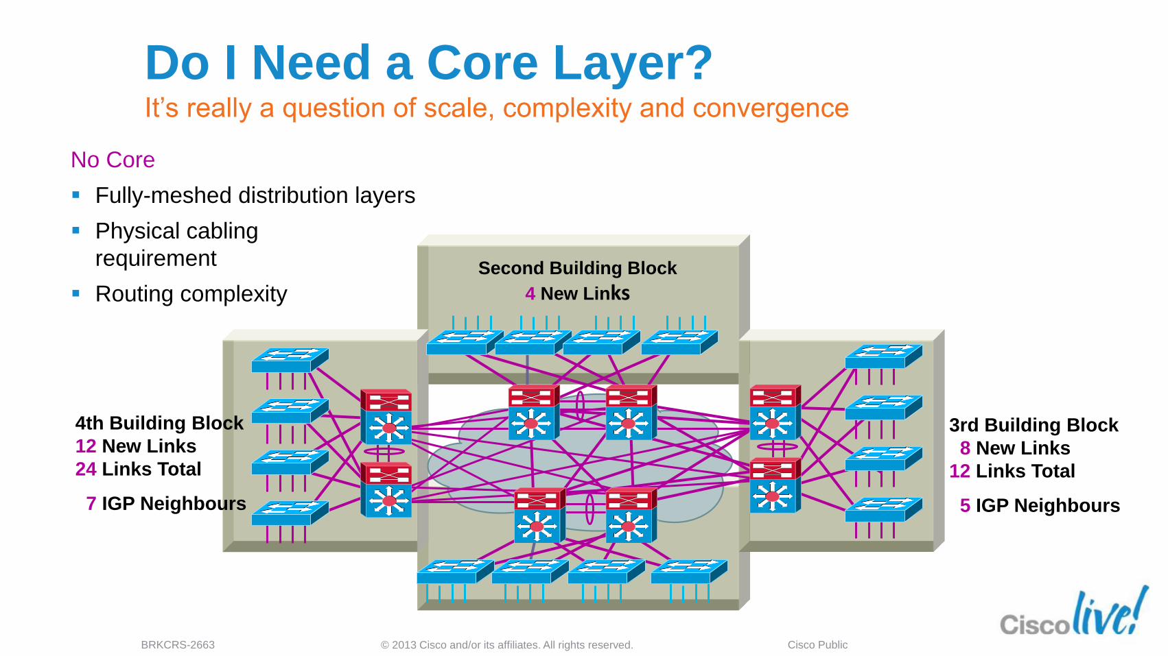
No Core
Fully-meshed distribution layers
Physical cabling
requirement
Routing complexity
4th Building Block
12 New Links
24 Links Total
7 IGP Neighbours
3rd Building Block
8 New Links
12 Links Total
5 IGP Neighbours
Second Building Block
4 New Links
Do I Need a Core Layer? It’s really a question of scale, complexity and convergence

© 2013 Cisco and/or its affiliates. All rights reserved. BRKCRS-2663 Cisco Public
Dedicated Core Switches Easier to add a module
Fewer links in the core
Easier bandwidth upgrade
Routing protocol peering reduced
Equal cost Layer 3 links for best convergence
4th Building Block
4 New Links
16 Links Total
3 IGP Neighbours
3rd Building Block
4 New Links
12 Links Total
3 IGP Neighbours
2nd Building Block
8 New Links
Do I Need a Core Layer? It’s really a question of scale, complexity and convergence

© 2013 Cisco and/or its affiliates. All rights reserved. BRKCRS-2663 Cisco Public 13
Access
Core
Distribution
Distribution
Access
Design Alternatives Within a Building
Block
Data Centre WAN Internet
SiSi SiSi SiSi SiSi
SiSi SiSi
SiSi SiSi
SiSi SiSiSiSi
SiSi
Layer 2 Access Routed Access Virtual Switching System
© 2013 Cisco and/or its affiliates. All rights reserved. BRKCRS-2663 Cisco Public 14
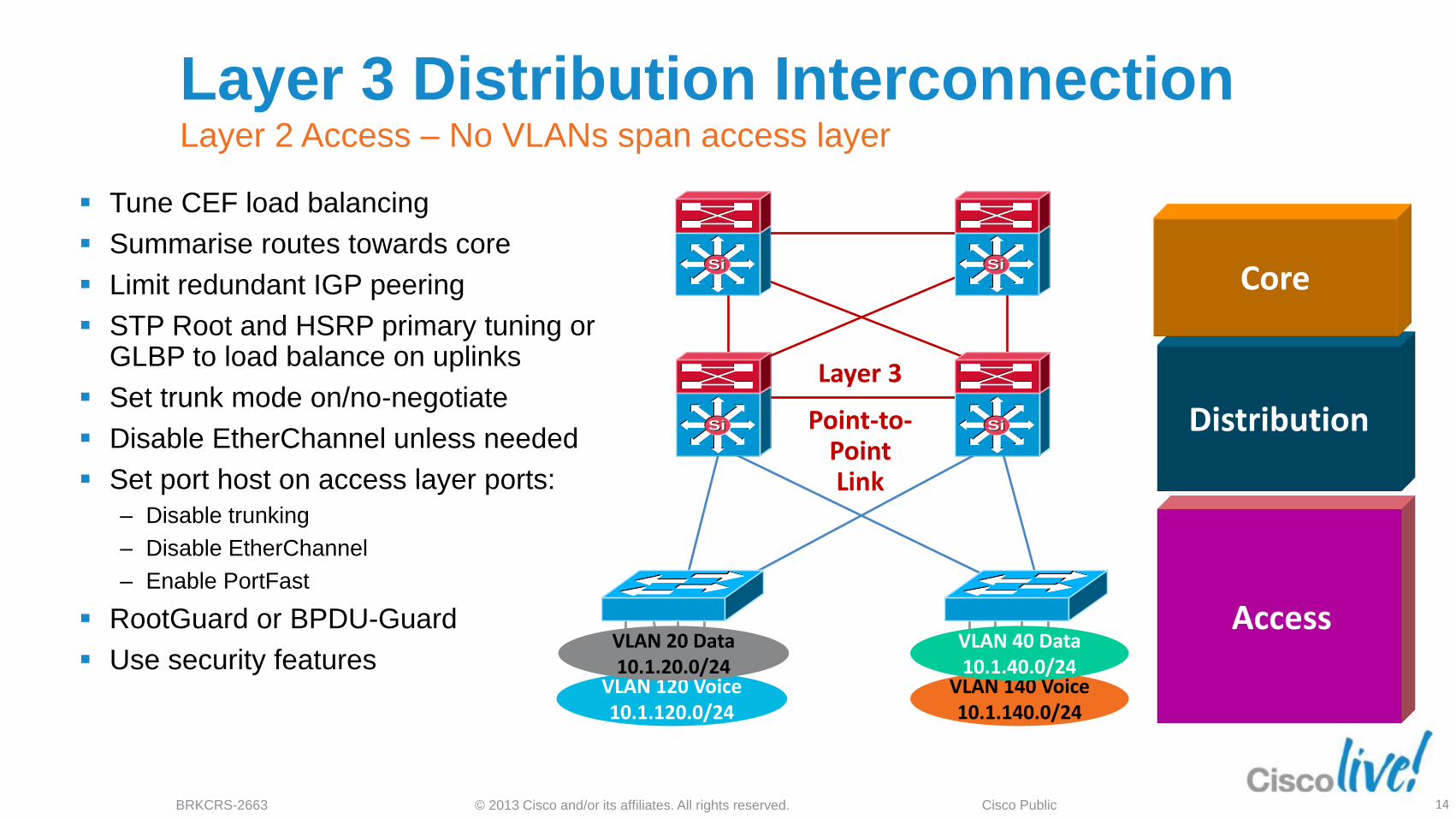
Layer 3 Distribution Interconnection Layer 2 Access – No VLANs span access layer
Tune CEF load balancing
Summarise routes towards core
Limit redundant IGP peering
STP Root and HSRP primary tuning or GLBP to load balance on uplinks
Set trunk mode on/no-negotiate
Disable EtherChannel unless needed
Set port host on access layer ports:
‒ Disable trunking
‒ Disable EtherChannel
‒ Enable PortFast
RootGuard or BPDU-Guard
Use security features
Access
Distribution
Core
VLAN 120 Voice 10.1.120.0/24
Point-to-Point Link
VLAN 20 Data 10.1.20.0/24
VLAN 140 Voice 10.1.140.0/24
SiSi SiSi
SiSi SiSi
VLAN 40 Data 10.1.40.0/24
Layer 3
© 2013 Cisco and/or its affiliates. All rights reserved. BRKCRS-2663 Cisco Public 15
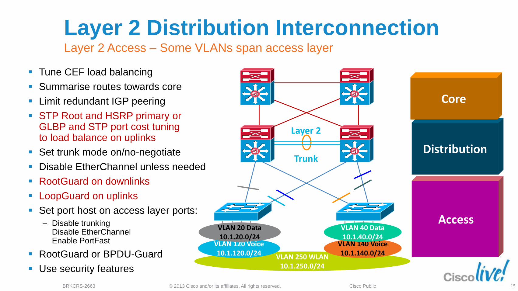
VLAN 250 WLAN 10.1.250.0/24
Layer 2 Distribution Interconnection Layer 2 Access – Some VLANs span access layer
Tune CEF load balancing
Summarise routes towards core
Limit redundant IGP peering
STP Root and HSRP primary or GLBP and STP port cost tuning to load balance on uplinks
Set trunk mode on/no-negotiate
Disable EtherChannel unless needed
RootGuard on downlinks
LoopGuard on uplinks
Set port host on access layer ports:
‒ Disable trunking Disable EtherChannel Enable PortFast
RootGuard or BPDU-Guard
Use security features
VLAN 120 Voice 10.1.120.0/24
Trunk
VLAN 20 Data 10.1.20.0/24
VLAN 140 Voice 10.1.140.0/24
SiSi SiSi
SiSi SiSi
Layer 2
VLAN 40 Data 10.1.40.0/24
Access
Distribution
Core

© 2013 Cisco and/or its affiliates. All rights reserved. BRKCRS-2663 Cisco Public 16
Routed Access and VSS Evolutions and improvements to existing designs
VLAN 120 Voice 10.1.120.0/24
P-to-P Link
Layer 3
VLAN 20 Data 10.1.20.0/24
VLAN 140 Voice 10.1.140.0/24
VLAN 40 Data 10.1.40.0/24
SiSi SiSi
SiSi SiSi
VLAN 20 Data VLAN 40 Data
AN 40 Data 10.1.40.0/24
SiSi SiSi
VLAN 120 Voice 10.1.120.0/24 VLAN 140 Voice 10.1.140.0/24 VLAN 250 WLAN 10.1.250.0/24
Access
Distribution
Core
VSS
© 2013 Cisco and/or its affiliates. All rights reserved. BRKCRS-2663 Cisco Public 17
Agenda
SiSiSiSi
SiSiSiSi
SiSi
Data Centre
SiSi SiSi
Services Block
Distribution Blocks
SiSi SiSi SiSi
Multilayer Campus
Design Principles
Foundation Services
Campus Design
Best Practices
Virtualisation techniques
Security considerations
What’s next….
Summary
© 2013 Cisco and/or its affiliates. All rights reserved. BRKCRS-2663 Cisco Public 18
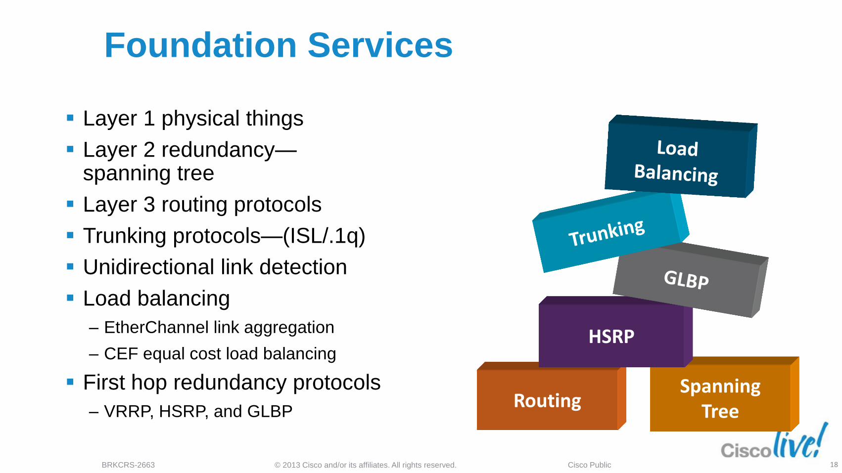
Foundation Services
Layer 1 physical things
Layer 2 redundancy— spanning tree
Layer 3 routing protocols
Trunking protocols—(ISL/.1q)
Unidirectional link detection
Load balancing
‒ EtherChannel link aggregation
‒ CEF equal cost load balancing
First hop redundancy protocols
‒ VRRP, HSRP, and GLBP
Spanning Tree
Routing
HSRP

© 2013 Cisco and/or its affiliates. All rights reserved. BRKCRS-2663 Cisco Public 19
Data Centre WAN Internet
Layer 3 Equal Cost Links
Layer 3 Equal Cost Links
SiSi SiSi SiSi SiSi SiSi SiSi
SiSiSiSi
SiSiSiSi
SiSi SiSiSiSiSiSi
Best Practices Layer 1 Physical Things
Use point-to-point
interconnections—no L2
aggregation points
between nodes
Use fibre for best
convergence
Tune carrier delay timer
Use configuration on the
physical interface not
VLAN/SVI when possible
© 2013 Cisco and/or its affiliates. All rights reserved. BRKCRS-2663 Cisco Public 20
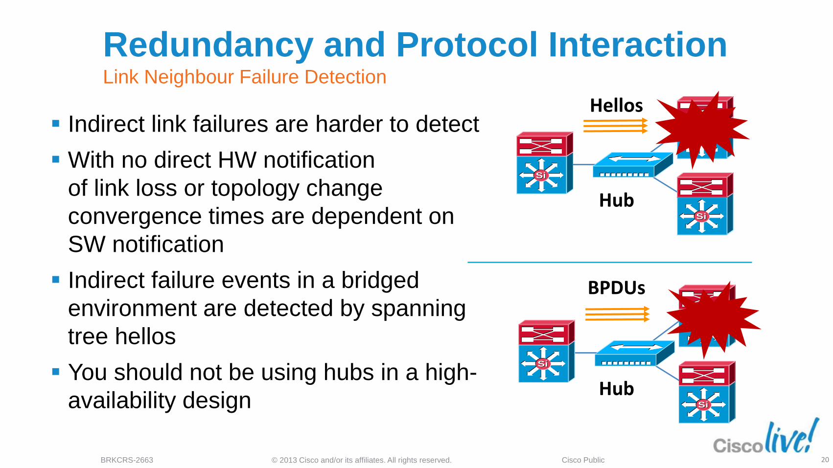
Redundancy and Protocol Interaction Link Neighbour Failure Detection
Indirect link failures are harder to detect
With no direct HW notification
of link loss or topology change
convergence times are dependent on
SW notification
Indirect failure events in a bridged
environment are detected by spanning
tree hellos
You should not be using hubs in a high-
availability design
SiSi
SiSi
SiSi
BPDUs
Hub
SiSi
SiSi
SiSi
Hub
Hellos
© 2013 Cisco and/or its affiliates. All rights reserved. BRKCRS-2663 Cisco Public 21
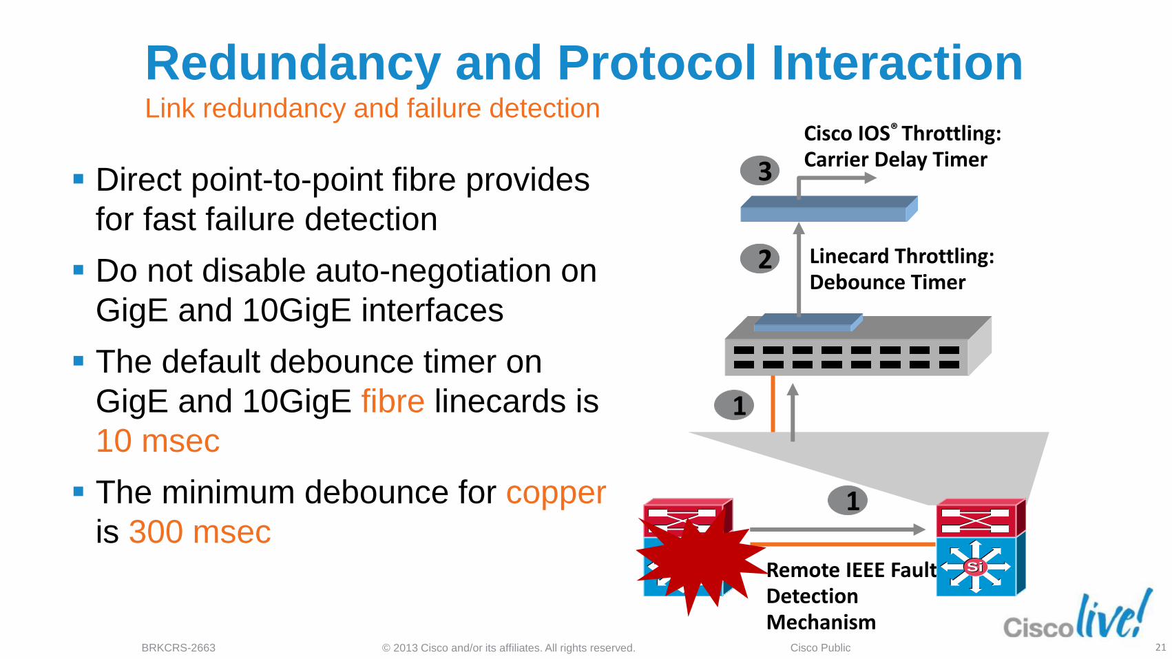
Redundancy and Protocol Interaction Link redundancy and failure detection
Direct point-to-point fibre provides
for fast failure detection
Do not disable auto-negotiation on
GigE and 10GigE interfaces
The default debounce timer on
GigE and 10GigE fibre linecards is
10 msec
The minimum debounce for copper
is 300 msec 1
2
3
Linecard Throttling: Debounce Timer
Remote IEEE Fault Detection Mechanism
Cisco IOS® Throttling: Carrier Delay Timer
SiSi SiSi
1
© 2013 Cisco and/or its affiliates. All rights reserved. BRKCRS-2663 Cisco Public
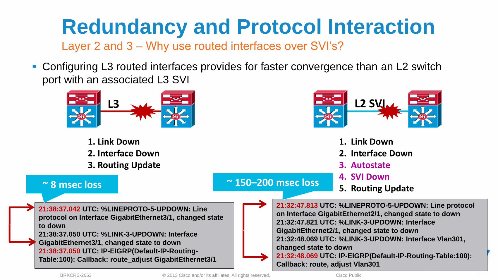
Redundancy and Protocol Interaction Layer 2 and 3 – Why use routed interfaces over SVI’s?
Configuring L3 routed interfaces provides for faster convergence than an L2 switch
port with an associated L3 SVI
21:32:47.813 UTC: %LINEPROTO-5-UPDOWN: Line protocol
on Interface GigabitEthernet2/1, changed state to down
21:32:47.821 UTC: %LINK-3-UPDOWN: Interface
GigabitEthernet2/1, changed state to down
21:32:48.069 UTC: %LINK-3-UPDOWN: Interface Vlan301,
changed state to down
21:32:48.069 UTC: IP-EIGRP(Default-IP-Routing-Table:100):
Callback: route, adjust Vlan301
21:38:37.042 UTC: %LINEPROTO-5-UPDOWN: Line
protocol on Interface GigabitEthernet3/1, changed state
to down
21:38:37.050 UTC: %LINK-3-UPDOWN: Interface
GigabitEthernet3/1, changed state to down
21:38:37.050 UTC: IP-EIGRP(Default-IP-Routing-
Table:100): Callback: route_adjust GigabitEthernet3/1
SiSiSiSi
L2 SVI SiSiSiSi
L3
~ 8 msec loss ~ 150–200 msec loss
1. Link Down 2. Interface Down 3. Autostate 4. SVI Down 5. Routing Update
1. Link Down 2. Interface Down 3. Routing Update
© 2013 Cisco and/or its affiliates. All rights reserved. BRKCRS-2663 Cisco Public 23
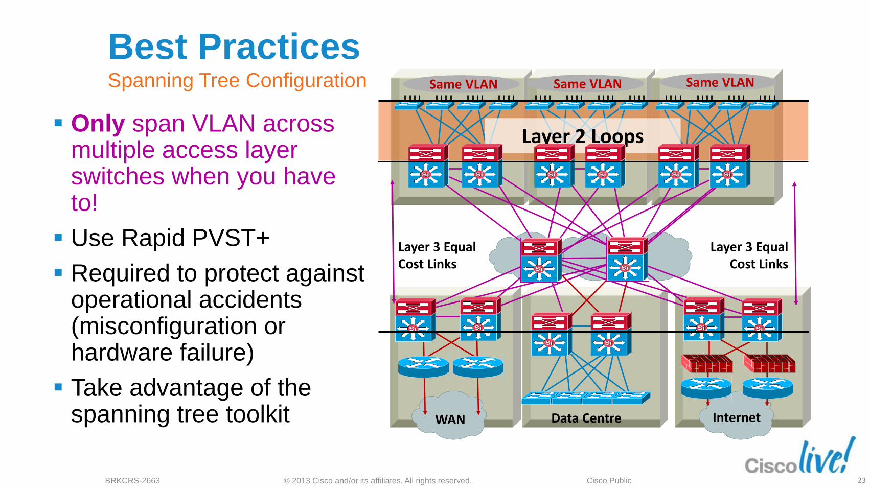
Best Practices Spanning Tree Configuration
Only span VLAN across multiple access layer switches when you have to!
Use Rapid PVST+
Required to protect against operational accidents (misconfiguration or hardware failure)
Take advantage of the spanning tree toolkit Data Centre WAN Internet
Layer 3 Equal Cost Links
Layer 3 Equal Cost Links
Layer 2 Loops
Same VLAN Same VLAN Same VLAN
SiSi SiSi SiSi SiSi SiSi SiSi
SiSiSiSi
SiSiSiSi
SiSi SiSiSiSiSiSi

© 2013 Cisco and/or its affiliates. All rights reserved. BRKCRS-2663 Cisco Public
Multilayer Network Design L2 access with L3 distribution
Each access switch has unique VLANs
No Layer 2 loops
Layer 3 link between distribution
No blocked links
At least some VLANs span multiple access
switches
Layer 2 loops, blocked links
Layer 2 and 3 running over link between
distribution
SiSi SiSi SiSi SiSi
Vlan 10 Vlan 20 Vlan 30 Vlan 30 Vlan 30 Vlan 30

© 2013 Cisco and/or its affiliates. All rights reserved. BRKCRS-2663 Cisco Public 25
0
5
10
15
20
25
30
35
PVST+ Rapid PVST+
Upstream
Downstream
Optimising L2 Convergence PVST+, Rapid PVST+ or MST
Rapid-PVST+ greatly improves the restoration times for any VLAN that requires a
topology convergence due to link UP
Rapid-PVST+ also greatly improves convergence time over backbone fast for any indirect
link failures
PVST+ (802.1d)
‒Traditional spanning tree implementation
Rapid PVST+ (802.1w) ‒Scales to large size (~10,000 logical ports)
‒Easy to implement, proven, scales
MST (802.1s) ‒Permits very large scale STP implementations
(~30,000 logical ports)
‒Not as flexible as rapid PVST+ Ti
me
to R
esto
re D
ata
Flo
ws
© 2013 Cisco and/or its affiliates. All rights reserved. BRKCRS-2663 Cisco Public 26
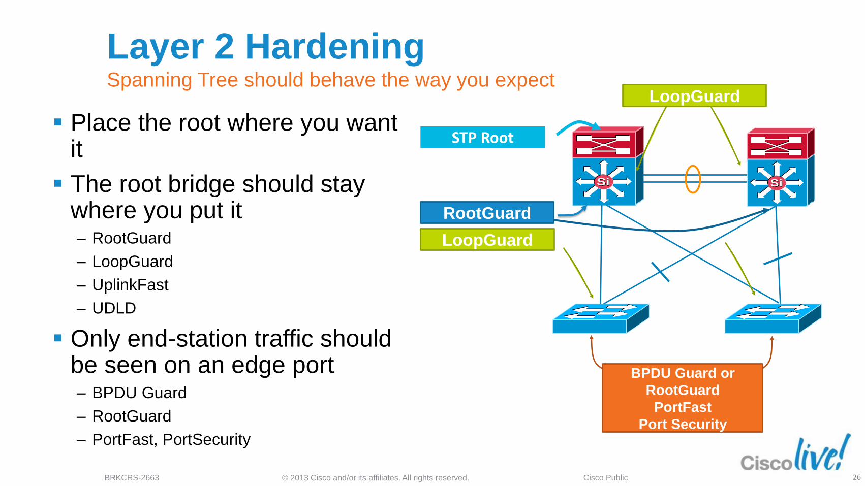
Layer 2 Hardening Spanning Tree should behave the way you expect
Place the root where you want it
The root bridge should stay where you put it ‒ RootGuard
‒ LoopGuard
‒ UplinkFast
‒ UDLD
Only end-station traffic should be seen on an edge port ‒ BPDU Guard
‒ RootGuard
‒ PortFast, PortSecurity
SiSiSiSi
BPDU Guard or
RootGuard
PortFast
Port Security
RootGuard
STP Root
LoopGuard
LoopGuard
© 2013 Cisco and/or its affiliates. All rights reserved. BRKCRS-2663 Cisco Public 27
Data Centre WAN Internet
Layer 3 Equal Cost Links
Layer 3 Equal Cost Links
SiSi SiSi SiSi SiSi SiSi SiSi
SiSiSiSi
SiSiSiSi
SiSi SiSiSiSiSiSi
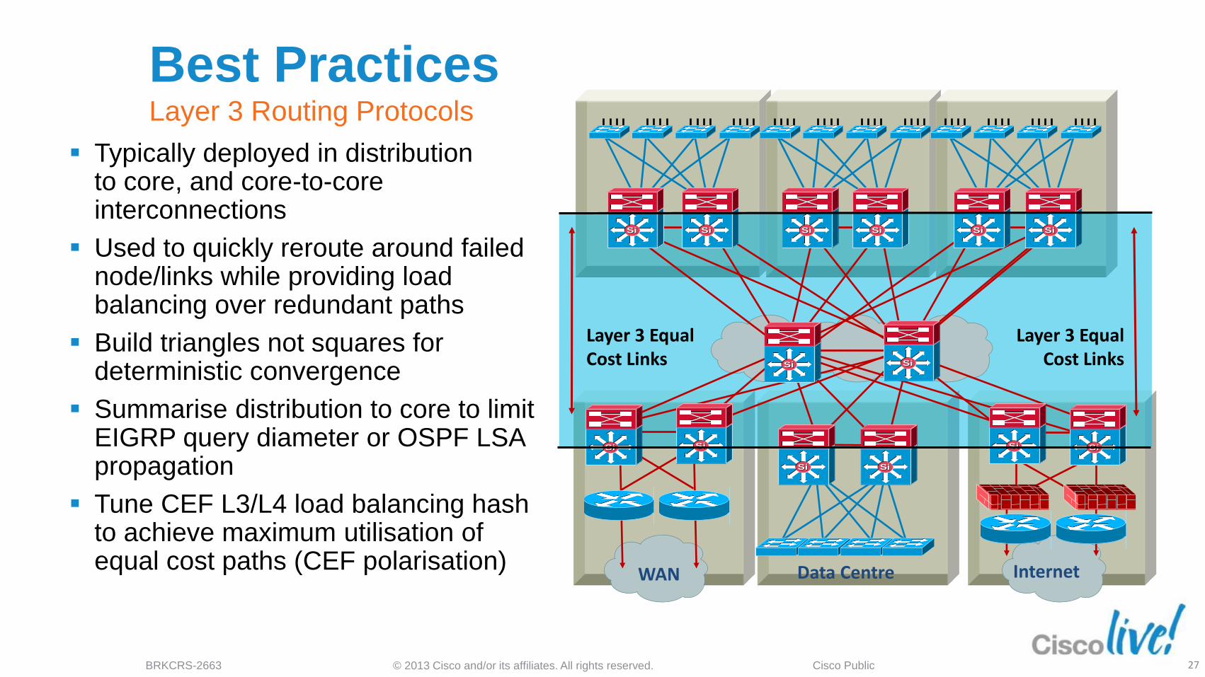
Best Practices Layer 3 Routing Protocols
Typically deployed in distribution to core, and core-to-core interconnections
Used to quickly reroute around failed node/links while providing load balancing over redundant paths
Build triangles not squares for deterministic convergence
Summarise distribution to core to limit EIGRP query diameter or OSPF LSA propagation
Tune CEF L3/L4 load balancing hash to achieve maximum utilisation of equal cost paths (CEF polarisation)
© 2013 Cisco and/or its affiliates. All rights reserved. BRKCRS-2663 Cisco Public 28
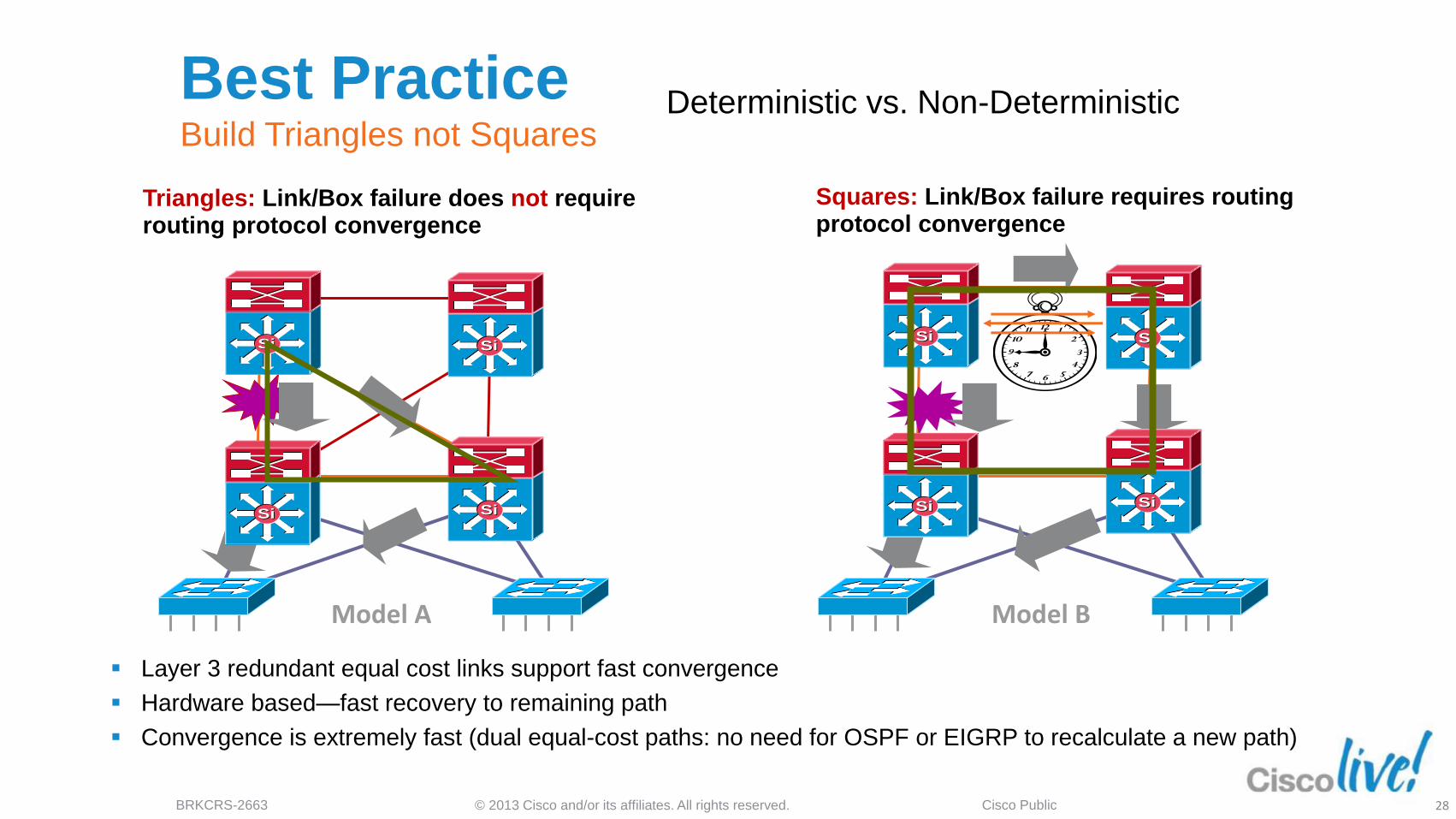
Best Practice Build Triangles not Squares
Layer 3 redundant equal cost links support fast convergence
Hardware based—fast recovery to remaining path
Convergence is extremely fast (dual equal-cost paths: no need for OSPF or EIGRP to recalculate a new path)
Triangles: Link/Box failure does not require routing protocol convergence
Model A
Squares: Link/Box failure requires routing protocol convergence
Model B
SiSi
SiSiSiSi
SiSiSiSi
SiSiSiSi
SiSi
Deterministic vs. Non-Deterministic

© 2013 Cisco and/or its affiliates. All rights reserved. BRKCRS-2663 Cisco Public 29
interface Port-channel1
description to Core#1
ip address 10.122.0.34 255.255.255.252
ip hello-interval eigrp 100 1
ip hold-time eigrp 100 3
ip summary-address eigrp 100 10.1.0.0
255.255.0.0 5
10.1.2.0/24 10.1.1.0/24
Summarise at the Distribution Limit EIGRP queries and OSPF LSA propagation
It is important to force summarisation at the distribution towards the core
For return path traffic an OSPF or EIGRP re-route is required
By limiting the number of peers an EIGRP router must query or the number of LSAs an OSPF peer must process we can optimise this reroute
EIGRP example:
SiSiSiSi
SiSi SiSi
Rest of Network
Access
Distribution
Core

© 2013 Cisco and/or its affiliates. All rights reserved. BRKCRS-2663 Cisco Public 30
SiSiSiSi
SiSi SiSi
Summarise at the Distribution Reduce the complexity of IGP convergence
It is important to force summarisation at the
distribution towards the core
For return path traffic an OSPF or EIGRP
re-route is required
By limiting the number of peers an EIGRP
router must query or the number of LSAs
an OSPF peer must process we can
optimise his reroute
For EIGRP if we summarise at the distribution we
stop queries at the core boxes for an access layer
flap
For OSPF when we summarise at the
distribution (area border or L1/L2 border)
the flooding of LSAs is limited to the
distribution switches; SPF now deals with one LSA
not three
10.1.2.0/24 10.1.1.0/24
Rest of Network
Summary:
10.1.0.0/16
Summaries stop queries at the core
Acces Access
Distribution
Core

© 2013 Cisco and/or its affiliates. All rights reserved. BRKCRS-2663 Cisco Public 31
Best practice - summarise at the
distribution layer to limit EIGRP queries
or OSPF LSA propagation
Gotcha:
‒ Upstream: HSRP on left distribution takes
over when link fails
‒ Return path: old router still advertises
summary to core
‒ Return traffic is dropped on right distribution
switch
Summarising requires a link between
the distribution switches
10.1.2.0/24 10.1.1.0/24
SiSiSiSi
SiSi SiSi
Access
Distribution
Core
Summarise at the Distribution Gotcha – Distribution to distribution link required
Summary:
10.1.0.0/16

© 2013 Cisco and/or its affiliates. All rights reserved. BRKCRS-2663 Cisco Public 32
Load-Sharing
Simple
Equal-Cost Multipath Optimising CEF load sharing
Depending on the traffic flow patterns and IP addressing in use, one algorithm may provide better load-sharing results than another
Be careful not to introduce polarisation in a multi-tier design by changing the default to the same thing in all tiers/layers of the network
SiSiSiSi
SiSi
30% of
flows 70% of
Flows
SiSiSiSiLoad-Sharing
Simple
Load-Sharing
Full Simple
* = Default Load-Sharing Mode
Catalyst 6500 Load-Sharing Options
Default* Src IP + Dst IP + Unique ID
Full Src IP + Dst IP + Src Port + Dst Port
Full Exclude Port Src IP + Dst IP + (Src or Dst Port)
Simple Src IP + Dst IP
Full Simple Src IP + Dst IP + Src Port + Dst Port
Catalyst 4500 Load-Sharing Options
Original Src IP + Dst IP
Universal* Src IP + Dst IP + Unique ID
Include Port Src IP + Dst IP + (Src or Dst Port) + Unique ID
SiSi SiSi
SiSi SiSi

© 2013 Cisco and/or its affiliates. All rights reserved. BRKCRS-2663 Cisco Public
SiSiSiSi
SiSi SiSi
SiSi SiSi
CEF Load Balancing Avoid underutilising redundant L3 paths
CEF polarisation: without some tuning
CEF will select the same path left/left or
right/right
Imbalance/overload could occur
Redundant paths are
ignored/underutilised
The default CEF hash input is L3
We can change the default to use L3 +
L4 information as input to the hash
derivation
L
L
R
R
Redundant Paths Ignored
Distribution
Default L3 Hash
Core
Default L3 Hash
Distribution
Default L3 Hash

© 2013 Cisco and/or its affiliates. All rights reserved. BRKCRS-2663 Cisco Public
SiSiSiSi
SiSi SiSi
SiSi SiSi
Depending on IP addressing and
flows, imbalance could occur
Alternating L3/L4 hash and L3 hash
will give us the best load balancing
results
Use simple in the core and full
simple in the distribution to add L4
information to the algorithm at the
distribution and maintain
differentiation tier-to-tier
R L
R L
R L
All Paths Used
Distribution
L3/L4 Hash
Core
Default L3 Hash
Distribution
L3/L4 Hash
CEF Load Balancing Avoid underutilising redundant L3 paths
© 2013 Cisco and/or its affiliates. All rights reserved. BRKCRS-2663 Cisco Public 35
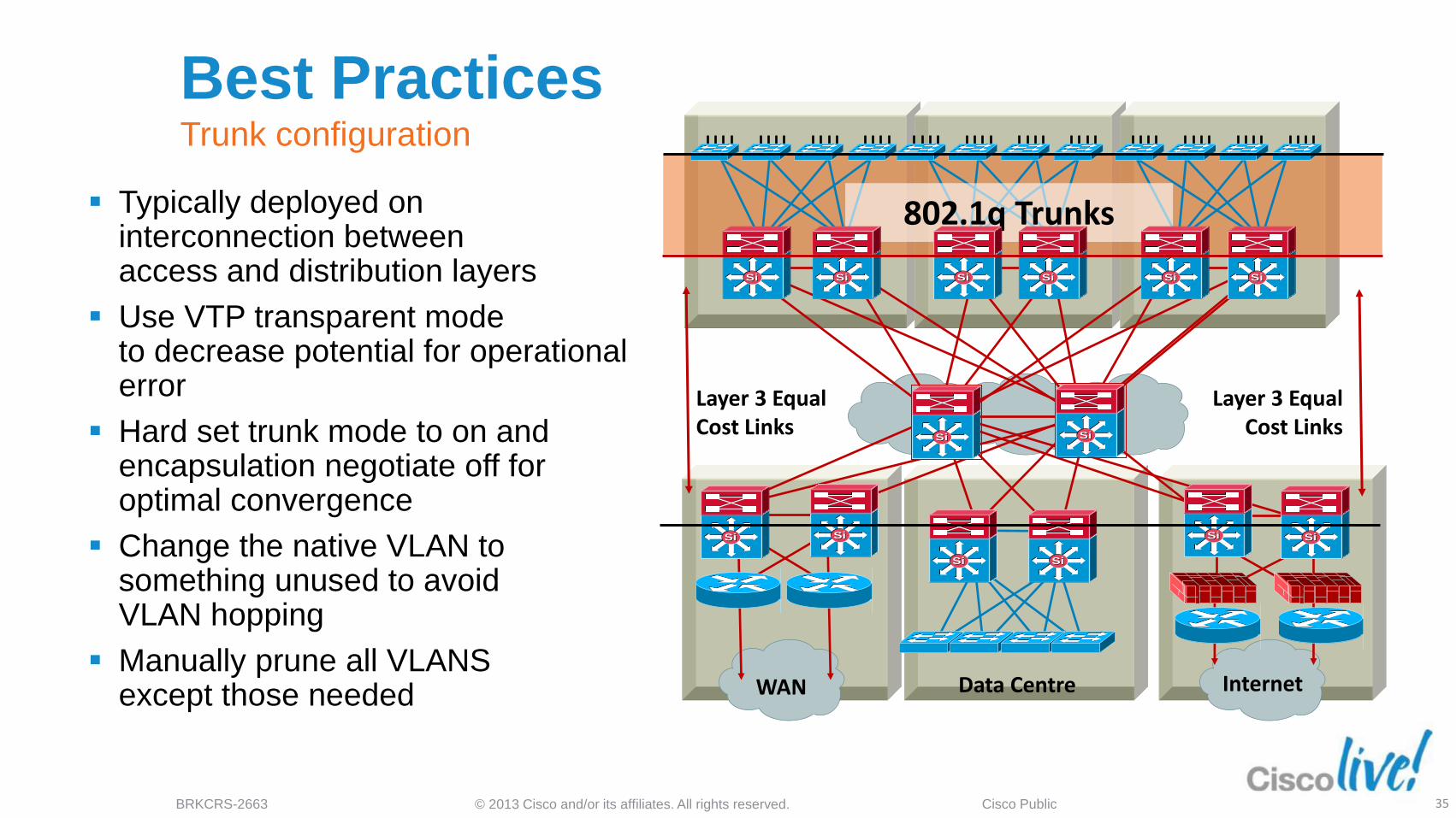
Typically deployed on interconnection between access and distribution layers
Use VTP transparent mode to decrease potential for operational error
Hard set trunk mode to on and encapsulation negotiate off for optimal convergence
Change the native VLAN to something unused to avoid VLAN hopping
Manually prune all VLANS except those needed Data Centre WAN Internet
Layer 3 Equal Cost Links
Layer 3 Equal Cost Links
802.1q Trunks
SiSi SiSi SiSi SiSi SiSi SiSi
SiSiSiSi
SiSiSiSi
SiSi SiSiSiSiSiSi
Best Practices Trunk configuration

© 2013 Cisco and/or its affiliates. All rights reserved. BRKCRS-2663 Cisco Public 36
VTP Virtual Trunk Protocol
Centralised VLAN management
VTP server switch propagates
VLAN database to VTP
client switches
Runs only on trunks
Four modes:
‒ Server: updates clients and servers
‒ Client: receive updates - cannot
make changes
‒ Transparent: let updates pass through
‒ Off: ignores VTP updates
F Server
Set
VLAN 50
Trunk
Trunk Trunk
Client
Off
Trunk
A
B
C
Client
Transparent
Ok, I Just
Learned
VLAN 50!
Drop VTP
Updates
Pass
Through
Update
Ok, I Just
Learned
VLAN 50!

© 2013 Cisco and/or its affiliates. All rights reserved. BRKCRS-2663 Cisco Public 37
DTP Dynamic Trunk Protocol
Automatic formation of trunked switch-to-
switch interconnection
‒ On: always be a trunk
‒ Desirable: ask if the other side can/will
‒ Auto: if the other sides asks I will
‒ Off: don’t become a trunk
Negotiation of 802.1Q or ISL encapsulation
‒ ISL: try to use ISL trunk encapsulation
‒ 802.1q: try to use 802.1q encapsulation
‒ Negotiate: negotiate ISL or 802.1q encapsulation with peer
‒ Non-negotiate: always use encapsulation that is hard set
On/On
Trunk
Auto/Desirable
Trunk
Off/Off
NO Trunk
Off/On, Auto, Desirable
NO Trunk
SiSi SiSi
SiSi SiSi
SiSi SiSi
SiSiSiSi
© 2013 Cisco and/or its affiliates. All rights reserved. BRKCRS-2663 Cisco Public 38
0
0.5
1
1.5
2
2.5
Trunking Desirable Trunking Nonegotiate
Tim
e to
Con
verg
e in
Sec
onds
3550 (Cisco IOS)
4006 (CatOS)
4507 (Cisco IOS)
6500 (CatOS)
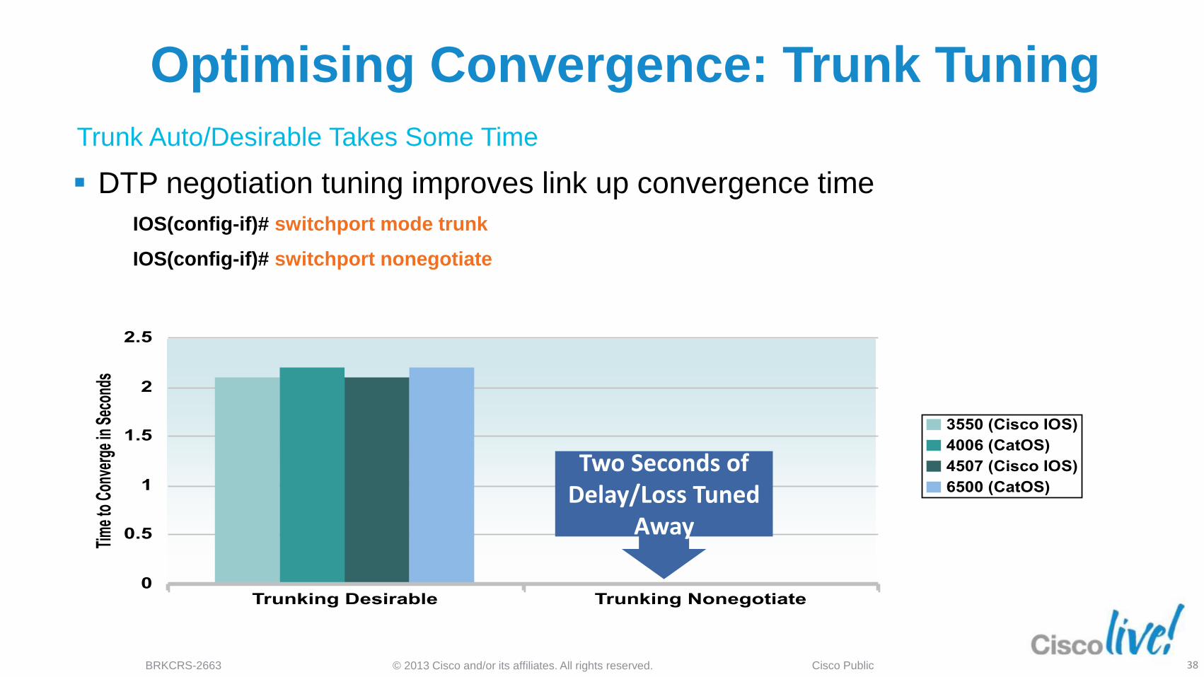
Optimising Convergence: Trunk Tuning
DTP negotiation tuning improves link up convergence time
IOS(config-if)# switchport mode trunk
IOS(config-if)# switchport nonegotiate
Two Seconds of Delay/Loss Tuned
Away
Trunk Auto/Desirable Takes Some Time
© 2013 Cisco and/or its affiliates. All rights reserved. BRKCRS-2663 Cisco Public 39
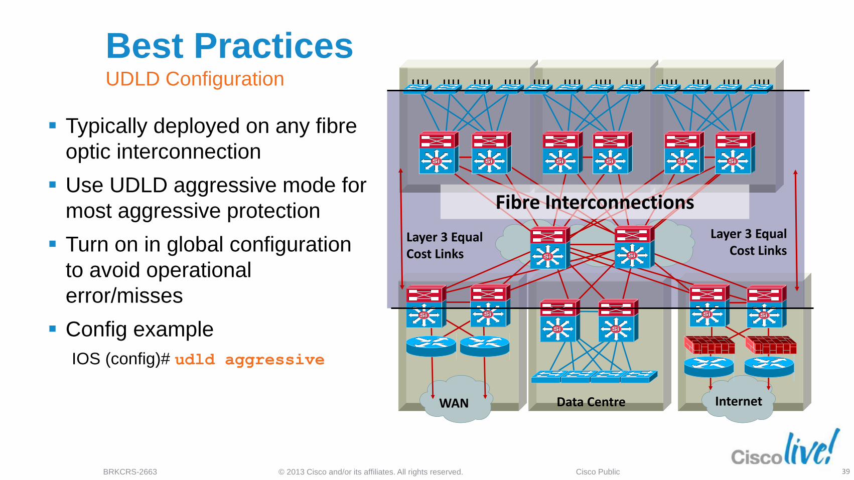
Best Practices UDLD Configuration
Typically deployed on any fibre
optic interconnection
Use UDLD aggressive mode for
most aggressive protection
Turn on in global configuration
to avoid operational
error/misses
Config example
IOS (config)# udld aggressive
Data Centre WAN Internet
Layer 3 Equal Cost Links
Layer 3 Equal Cost Links
Fibre Interconnections
SiSi SiSi SiSi SiSi SiSi SiSi
SiSiSiSi
SiSiSiSi
SiSi SiSiSiSiSiSi
© 2013 Cisco and/or its affiliates. All rights reserved. BRKCRS-2663 Cisco Public 40
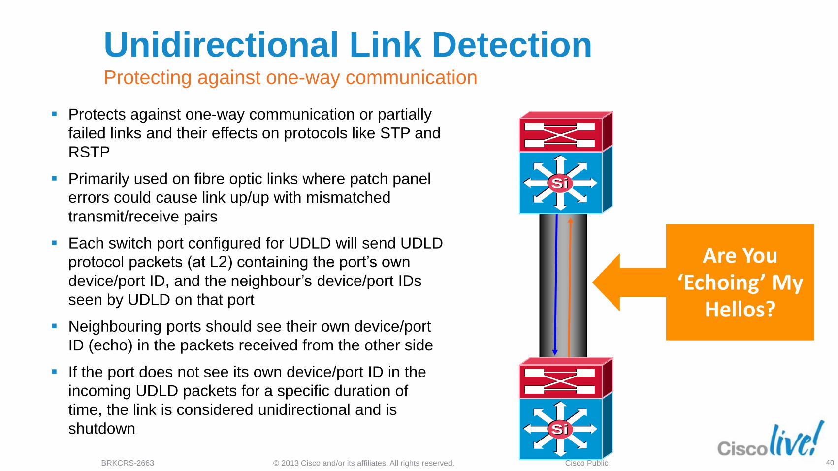
Unidirectional Link Detection Protecting against one-way communication
Protects against one-way communication or partially
failed links and their effects on protocols like STP and
RSTP
Primarily used on fibre optic links where patch panel
errors could cause link up/up with mismatched
transmit/receive pairs
Each switch port configured for UDLD will send UDLD
protocol packets (at L2) containing the port’s own
device/port ID, and the neighbour’s device/port IDs
seen by UDLD on that port
Neighbouring ports should see their own device/port
ID (echo) in the packets received from the other side
If the port does not see its own device/port ID in the
incoming UDLD packets for a specific duration of
time, the link is considered unidirectional and is
shutdown
Are You ‘Echoing’ My
Hellos?
SiSi
SiSi

© 2013 Cisco and/or its affiliates. All rights reserved. BRKCRS-2663 Cisco Public 41
UDLD Modes: Aggressive and Normal
Timers are the same - 15-second hellos by default
UDLD Normal Mode - only err-disable the end where UDLD
detected. The other end just sees the link go down
UDLD Aggressive Mode - err-disable both ends of the connection.
Could lead to complete loss of connectivity to remote site
SiSi SiSi
© 2013 Cisco and/or its affiliates. All rights reserved. BRKCRS-2663 Cisco Public 42
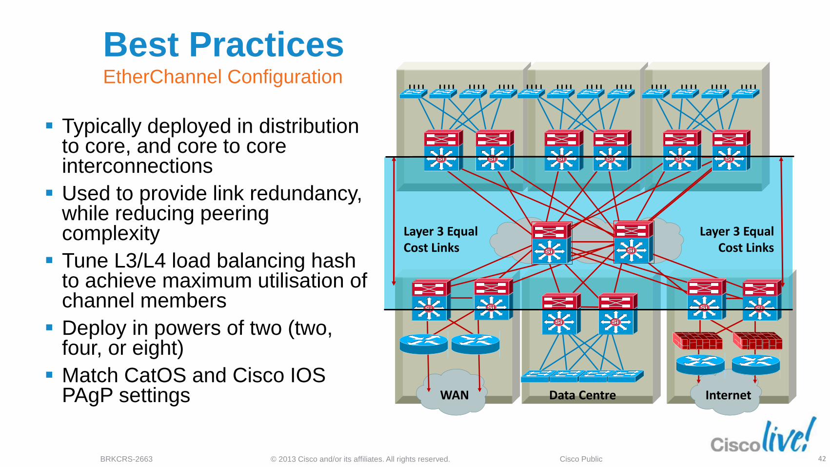
Best Practices EtherChannel Configuration
Typically deployed in distribution to core, and core to core interconnections
Used to provide link redundancy, while reducing peering complexity
Tune L3/L4 load balancing hash to achieve maximum utilisation of channel members
Deploy in powers of two (two, four, or eight)
Match CatOS and Cisco IOS PAgP settings Data Centre WAN Internet
Layer 3 Equal Cost Links
Layer 3 Equal Cost Links
SiSi SiSi SiSi SiSi SiSi SiSi
SiSiSiSi
SiSiSiSi
SiSi SiSiSiSiSiSi
© 2013 Cisco and/or its affiliates. All rights reserved. BRKCRS-2663 Cisco Public 43
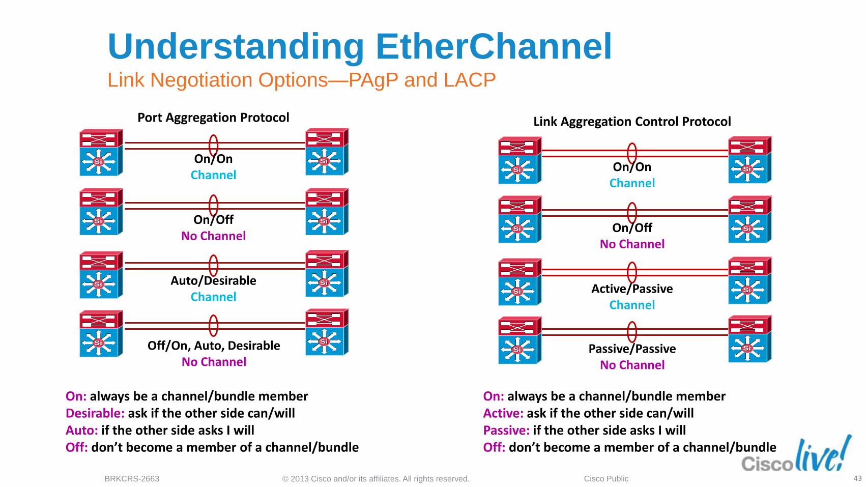
Understanding EtherChannel Link Negotiation Options—PAgP and LACP
On/On Channel
On/Off No Channel
Auto/Desirable Channel
Off/On, Auto, Desirable No Channel
SiSi SiSi
SiSi SiSi
SiSi SiSi
SiSiSiSi
On/On Channel
On/Off No Channel
Active/Passive Channel
Passive/Passive No Channel
SiSi
SiSi SiSi
SiSi SiSi
SiSiSiSi
SiSi
Port Aggregation Protocol Link Aggregation Control Protocol
On: always be a channel/bundle member Active: ask if the other side can/will Passive: if the other side asks I will Off: don’t become a member of a channel/bundle
On: always be a channel/bundle member Desirable: ask if the other side can/will Auto: if the other side asks I will Off: don’t become a member of a channel/bundle
© 2013 Cisco and/or its affiliates. All rights reserved. BRKCRS-2663 Cisco Public 44
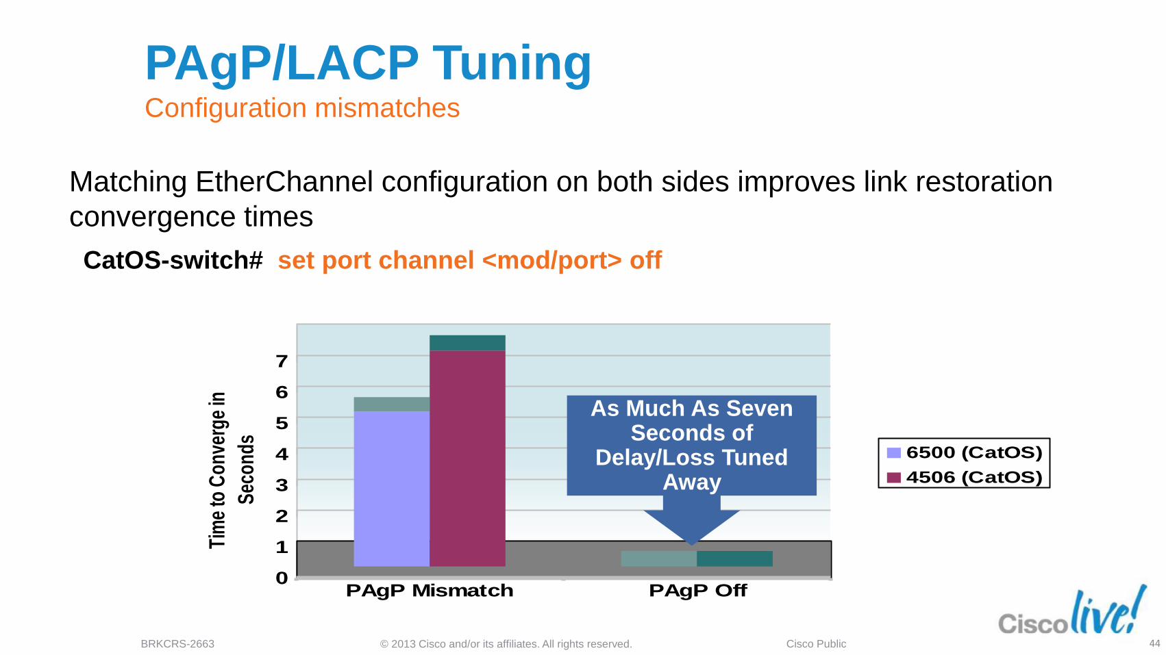
PAgP/LACP Tuning Configuration mismatches
Matching EtherChannel configuration on both sides improves link restoration
convergence times
CatOS-switch# set port channel <mod/port> off
0
1
2
3
4
5
6
7
Tim
e to
Con
verg
e in
Sec
onds
PAgP Mismatch PAgP Off
6500 (CatOS)
4506 (CatOS)
As Much As Seven Seconds of
Delay/Loss Tuned Away

© 2013 Cisco and/or its affiliates. All rights reserved. BRKCRS-2663 Cisco Public
EtherChannel link load sharing
Default L3 (src/dst IP) hash determines which link to use in etherchannel
‒ Can lead to unbalanced utilisation
Change default to include L4 information
‒ Configured globally or on individual etherchannels.
SiSiSiSi
L3 Hash Link 0 load – 68%
Link 1 load – 32%
L3/4 Hash Link 0 load – 52%
Link 1 load – 48%
SiSi SiSi
Switch(config)# port-channel load-balance src-dst-port

© 2013 Cisco and/or its affiliates. All rights reserved. BRKCRS-2663 Cisco Public 46
Best Practices First Hop Redundancy
Used to provide a resilient default
gateway to end-stations
HSRP, VRRP, and GLBP
alternatives
VRRP, HSRP, and GLBP provide
millisecond timers and excellent
convergence performance
VRRP if you need multivendor
interoperability
GLBP facilitates uplink load
balancing
Preempt timers need to be tuned
to avoid black-holed traffic
Data Centre WAN Internet
Layer 3 Equal Cost Links
Layer 3 Equal Cost Links
1st Hop Redundancy
SiSi SiSi SiSi SiSi SiSi SiSi
SiSiSiSi
SiSiSiSi
SiSi SiSiSiSiSiSi
© 2013 Cisco and/or its affiliates. All rights reserved. BRKCRS-2663 Cisco Public 47
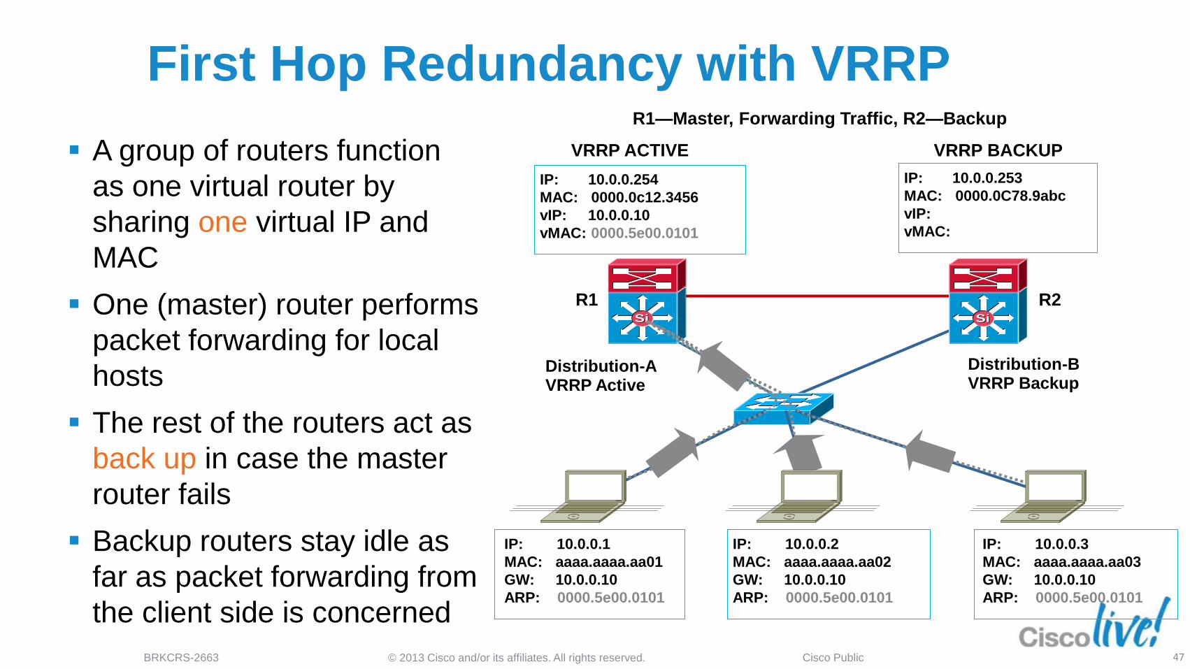
First Hop Redundancy with VRRP
A group of routers function
as one virtual router by
sharing one virtual IP and
MAC
One (master) router performs
packet forwarding for local
hosts
The rest of the routers act as
back up in case the master
router fails
Backup routers stay idle as
far as packet forwarding from
the client side is concerned
R1—Master, Forwarding Traffic, R2—Backup
VRRP ACTIVE VRRP BACKUP
IP: 10.0.0.254
MAC: 0000.0c12.3456
vIP: 10.0.0.10
vMAC: 0000.5e00.0101
IP: 10.0.0.253
MAC: 0000.0C78.9abc
vIP:
vMAC:
IP: 10.0.0.1
MAC: aaaa.aaaa.aa01
GW: 10.0.0.10
ARP: 0000.5e00.0101
IP: 10.0.0.2
MAC: aaaa.aaaa.aa02
GW: 10.0.0.10
ARP: 0000.5e00.0101
IP: 10.0.0.3
MAC: aaaa.aaaa.aa03
GW: 10.0.0.10
ARP: 0000.5e00.0101
SiSiSiSi
Access-a
Distribution-A VRRP Active
Distribution-B VRRP Backup
R1 R2
© 2013 Cisco and/or its affiliates. All rights reserved. BRKCRS-2663 Cisco Public 48
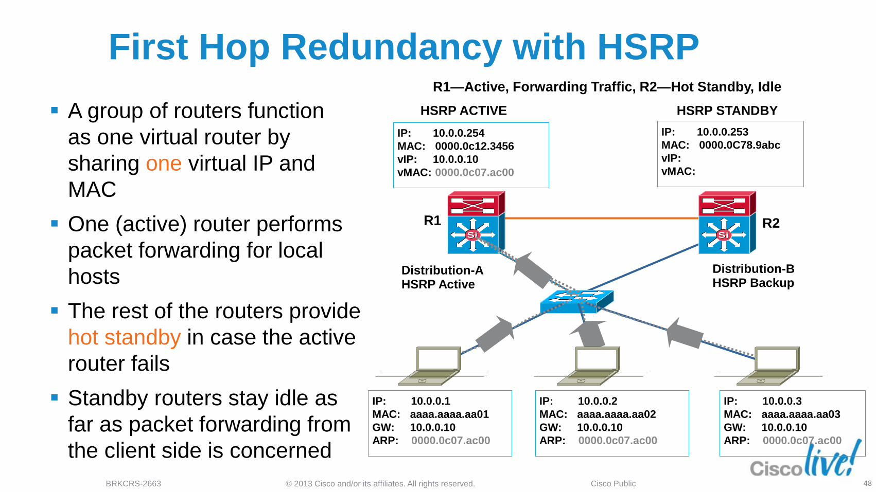
First Hop Redundancy with HSRP
A group of routers function
as one virtual router by
sharing one virtual IP and
MAC
One (active) router performs
packet forwarding for local
hosts
The rest of the routers provide
hot standby in case the active
router fails
Standby routers stay idle as
far as packet forwarding from
the client side is concerned
IP: 10.0.0.1
MAC: aaaa.aaaa.aa01
GW: 10.0.0.10
ARP: 0000.0c07.ac00
SiSiSiSi
Access-a
R1
HSRP ACTIVE HSRP STANDBY
IP: 10.0.0.254
MAC: 0000.0c12.3456
vIP: 10.0.0.10
vMAC: 0000.0c07.ac00
IP: 10.0.0.253
MAC: 0000.0C78.9abc
vIP:
vMAC:
IP: 10.0.0.2
MAC: aaaa.aaaa.aa02
GW: 10.0.0.10
ARP: 0000.0c07.ac00
IP: 10.0.0.3
MAC: aaaa.aaaa.aa03
GW: 10.0.0.10
ARP: 0000.0c07.ac00
R1—Active, Forwarding Traffic, R2—Hot Standby, Idle
R2
Distribution-A HSRP Active
Distribution-B HSRP Backup
© 2013 Cisco and/or its affiliates. All rights reserved. BRKCRS-2663 Cisco Public 49
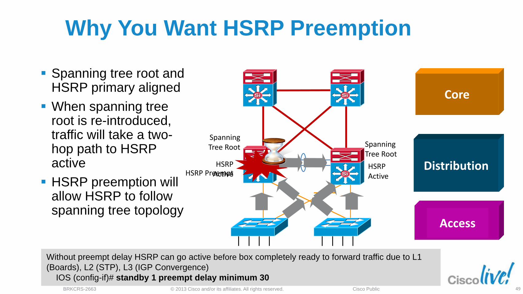
Why You Want HSRP Preemption
Spanning tree root and HSRP primary aligned
When spanning tree root is re-introduced, traffic will take a two-hop path to HSRP active
HSRP preemption will allow HSRP to follow spanning tree topology
SiSiSiSi
SiSiSiSi
Access
Distribution
Core
Spanning Tree Root
HSRP Active
HSRP Active
Spanning Tree Root
HSRP Preempt
Without preempt delay HSRP can go active before box completely ready to forward traffic due to L1
(Boards), L2 (STP), L3 (IGP Convergence)
IOS (config-if)# standby 1 preempt delay minimum 30
© 2013 Cisco and/or its affiliates. All rights reserved. BRKCRS-2663 Cisco Public 50
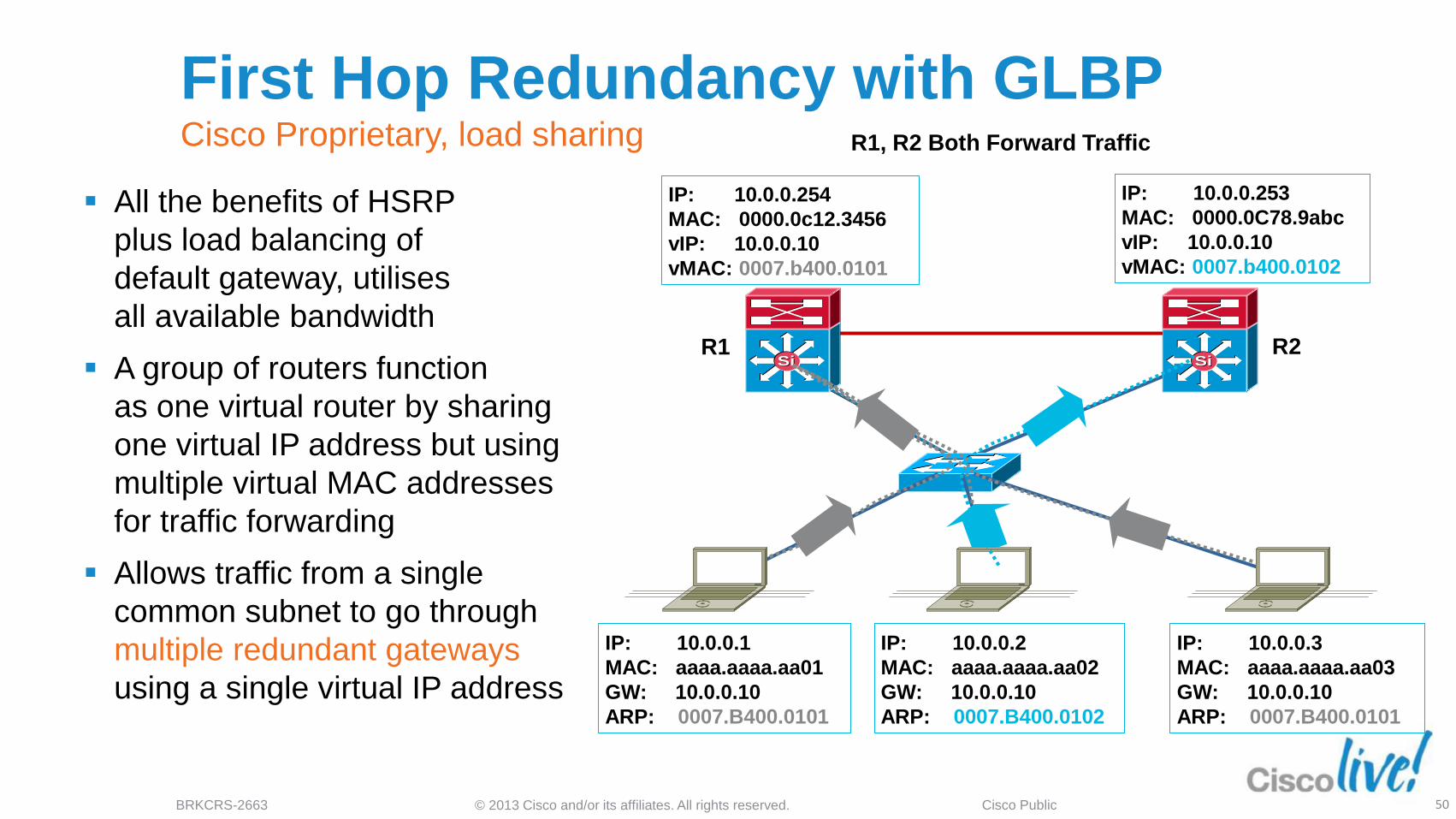
First Hop Redundancy with GLBP Cisco Proprietary, load sharing
All the benefits of HSRP
plus load balancing of
default gateway, utilises
all available bandwidth
A group of routers function
as one virtual router by sharing
one virtual IP address but using
multiple virtual MAC addresses
for traffic forwarding
Allows traffic from a single
common subnet to go through
multiple redundant gateways
using a single virtual IP address
R1, R2 Both Forward Traffic
IP: 10.0.0.254
MAC: 0000.0c12.3456
vIP: 10.0.0.10
vMAC: 0007.b400.0101
IP: 10.0.0.253
MAC: 0000.0C78.9abc
vIP: 10.0.0.10
vMAC: 0007.b400.0102
IP: 10.0.0.1
MAC: aaaa.aaaa.aa01
GW: 10.0.0.10
ARP: 0007.B400.0101
IP: 10.0.0.2
MAC: aaaa.aaaa.aa02
GW: 10.0.0.10
ARP: 0007.B400.0102
IP: 10.0.0.3
MAC: aaaa.aaaa.aa03
GW: 10.0.0.10
ARP: 0007.B400.0101
SiSiSiSi
Access-a
R1 R2
© 2013 Cisco and/or its affiliates. All rights reserved. BRKCRS-2663 Cisco Public
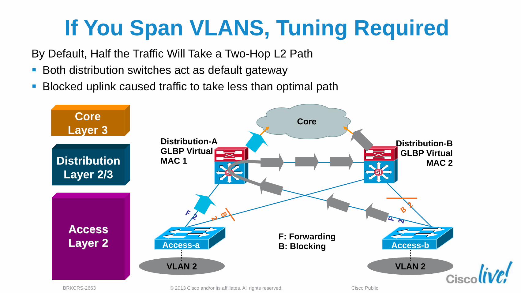
If You Span VLANS, Tuning Required By Default, Half the Traffic Will Take a Two-Hop L2 Path
Both distribution switches act as default gateway
Blocked uplink caused traffic to take less than optimal path
VLAN 2 VLAN 2
F: Forwarding B: Blocking Access-b
SiSiSiSi
Core
Access-a
Distribution-A GLBP Virtual MAC 1
Distribution-B GLBP Virtual
MAC 2
Access
Layer 2
Distribution
Layer 2/3
Core
Layer 3
© 2013 Cisco and/or its affiliates. All rights reserved. BRKCRS-2663 Cisco Public
SiSiSiSi
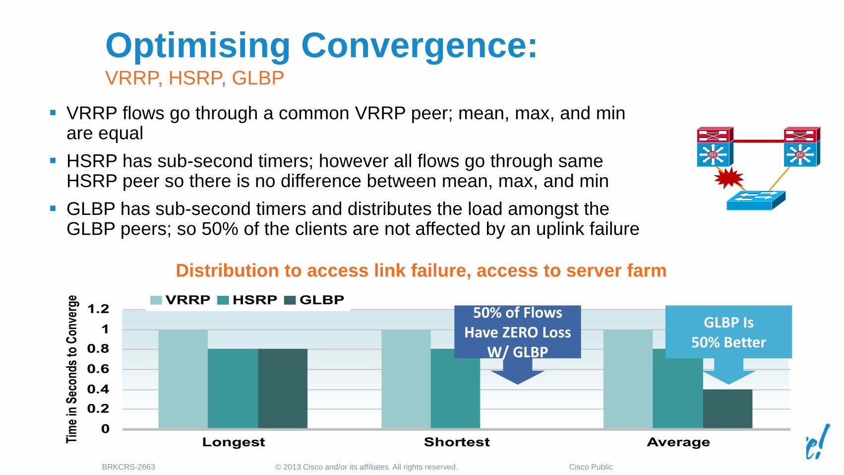
Optimising Convergence: VRRP, HSRP, GLBP
VRRP flows go through a common VRRP peer; mean, max, and min are equal
HSRP has sub-second timers; however all flows go through same HSRP peer so there is no difference between mean, max, and min
GLBP has sub-second timers and distributes the load amongst the GLBP peers; so 50% of the clients are not affected by an uplink failure
Distribution to access link failure, access to server farm
50% of Flows Have ZERO Loss
W/ GLBP
GLBP Is 50% Better
© 2013 Cisco and/or its affiliates. All rights reserved. BRKCRS-2663 Cisco Public 53
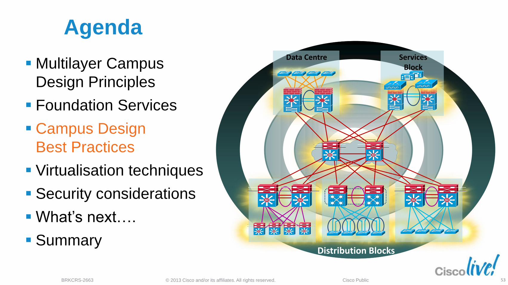
Agenda
SiSiSiSi
SiSiSiSi
SiSi
Data Centre
SiSi SiSi
Services Block
Distribution Blocks
SiSi SiSi SiSi
Multilayer Campus
Design Principles
Foundation Services
Campus Design
Best Practices
Virtualisation techniques
Security considerations
What’s next….
Summary

© 2013 Cisco and/or its affiliates. All rights reserved. BRKCRS-2663 Cisco Public 54
VLAN 2 VLAN 2 VLAN 2
Distribution-A Distribution-B
Access-c Access-a
Layer 3 Link
Access-n
Daisy Chaining Access Layer Switches Avoid potential black holes
Return Path Traffic Has a 50/50 Chance of Being ‘Black Holed’
SiSiSiSi
SiSiSiSi
Access
Layer 2
Distribution
Layer 2/3
Core
Layer 3 50% Chance That Traffic Will
Go Down Path with No
Connectivity

© 2013 Cisco and/or its affiliates. All rights reserved. BRKCRS-2663 Cisco Public
Daisy Chaining Access Layer Switches New technology addresses old problems
Stackwise/Stackwise-Plus
technology eliminates the
concern
‒ Loopback links not required
‒ No longer forced to have L2 link in
distribution
If you use modular (chassis-
based) switches, these
problems are not a concern
HSRP Active HSRP Standby
Forwarding Forwarding
3750-E
SiSi SiSi
Layer 3 Distribution
Layer 2/3
Access
Layer 2
© 2013 Cisco and/or its affiliates. All rights reserved. BRKCRS-2663 Cisco Public 56
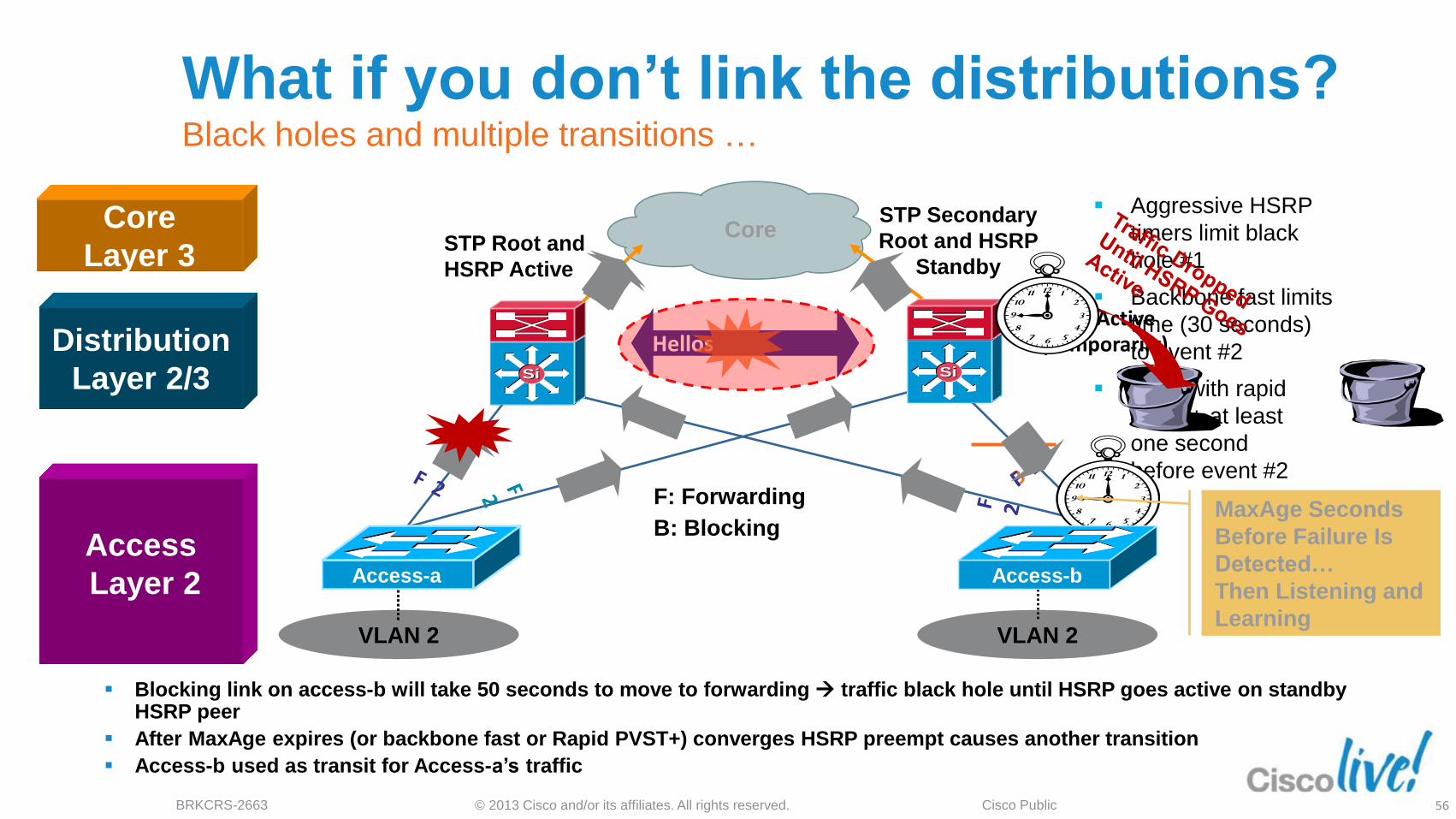
Aggressive HSRP
timers limit black
hole #1
Backbone fast limits
time (30 seconds)
to event #2
Even with rapid
PVST+ at least
one second
before event #2
VLAN 2 VLAN 2
What if you don’t link the distributions? Black holes and multiple transitions …
Blocking link on access-b will take 50 seconds to move to forwarding traffic black hole until HSRP goes active on standby HSRP peer
After MaxAge expires (or backbone fast or Rapid PVST+) converges HSRP preempt causes another transition
Access-b used as transit for Access-a’s traffic
HSRP Active (Temporarily)
MaxAge Seconds
Before Failure Is
Detected…
Then Listening and
Learning
F: Forwarding
B: Blocking
Access-b
SiSiSiSi
Hellos
Access
Layer 2
Distribution
Layer 2/3
Core
Layer 3 Core
STP Root and
HSRP Active
STP Secondary
Root and HSRP
Standby
Access-a
© 2013 Cisco and/or its affiliates. All rights reserved. BRKCRS-2663 Cisco Public 57
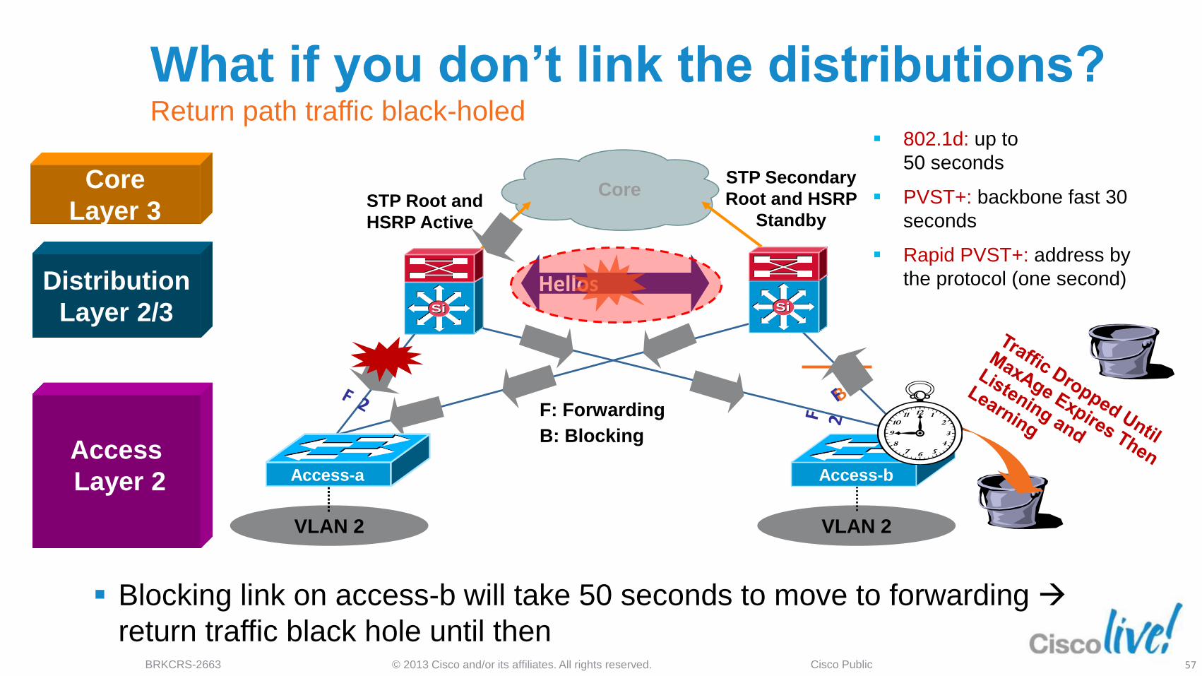
802.1d: up to
50 seconds
PVST+: backbone fast 30
seconds
Rapid PVST+: address by
the protocol (one second)
VLAN 2 VLAN 2
Blocking link on access-b will take 50 seconds to move to forwarding
return traffic black hole until then
Hellos
Access-b
SiSiSiSi
Access Layer 2
Access-a
What if you don’t link the distributions? Return path traffic black-holed
Access
Layer 2
Distribution
Layer 2/3
Core
Layer 3
F: Forwarding
B: Blocking
STP Root and
HSRP Active
STP Secondary
Root and HSRP
Standby
Core
© 2013 Cisco and/or its affiliates. All rights reserved. BRKCRS-2663 Cisco Public 58
VLAN 2 VLAN 2
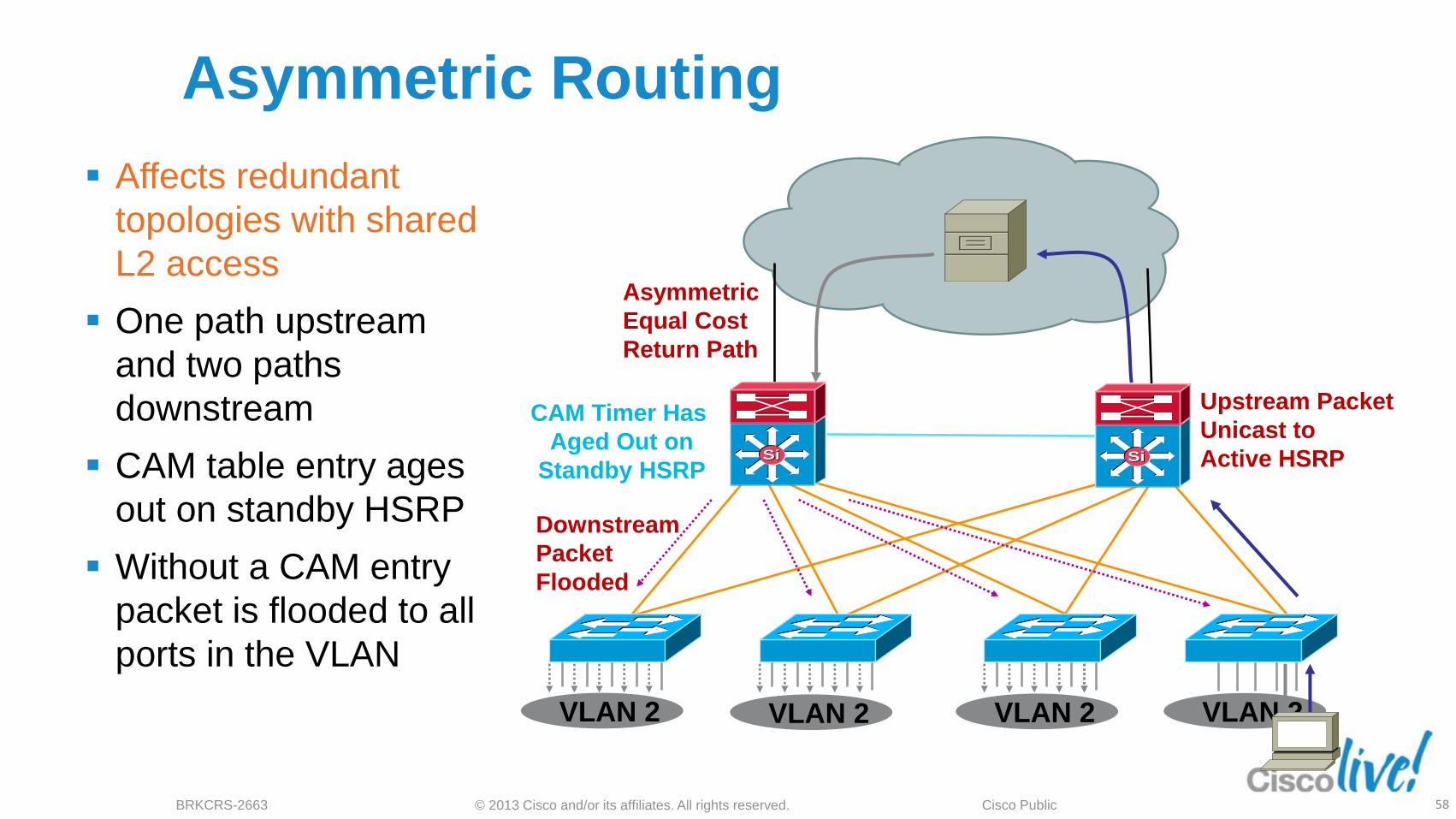
Asymmetric Routing
Affects redundant
topologies with shared
L2 access
One path upstream
and two paths
downstream
CAM table entry ages
out on standby HSRP
Without a CAM entry
packet is flooded to all
ports in the VLAN
Downstream
Packet
Flooded
Upstream Packet
Unicast to
Active HSRP
Asymmetric
Equal Cost
Return Path
CAM Timer Has
Aged Out on
Standby HSRP
VLAN 2 VLAN 2
SiSi SiSi
© 2013 Cisco and/or its affiliates. All rights reserved. BRKCRS-2663 Cisco Public 59
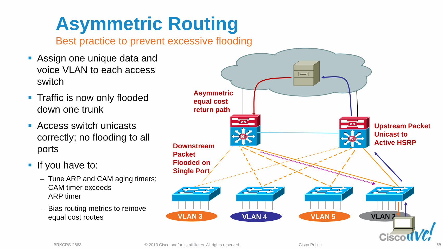
VLAN 2
Assign one unique data and
voice VLAN to each access
switch
Traffic is now only flooded
down one trunk
Access switch unicasts
correctly; no flooding to all
ports
If you have to:
‒ Tune ARP and CAM aging timers;
CAM timer exceeds
ARP timer
‒ Bias routing metrics to remove
equal cost routes
Downstream
Packet
Flooded on
Single Port
Upstream Packet
Unicast to
Active HSRP
Asymmetric
equal cost
return path
VLAN 3 VLAN 4 VLAN 5
SiSiSiSi
Asymmetric Routing Best practice to prevent excessive flooding

© 2013 Cisco and/or its affiliates. All rights reserved. BRKCRS-2663 Cisco Public 60
Agenda
SiSiSiSi
SiSiSiSi
SiSi
Data Centre
SiSi SiSi
Services Block
Distribution Blocks
SiSi SiSi SiSi
Multilayer Campus
Design Principles
Foundation Services
Campus Design
Best Practices
Virtualisation techniques
Security considerations
What’s next….
Summary
© 2013 Cisco and/or its affiliates. All rights reserved. BRKCRS-2663 Cisco Public
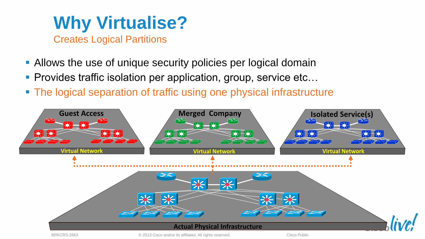
Guest Access
Virtual Network
Why Virtualise? Creates Logical Partitions
Allows the use of unique security policies per logical domain
Provides traffic isolation per application, group, service etc…
The logical separation of traffic using one physical infrastructure
Actual Physical Infrastructure
Virtual Network
Merged Company
Virtual Network
Isolated Service(s)
© 2013 Cisco and/or its affiliates. All rights reserved. BRKCRS-2663 Cisco Public 62
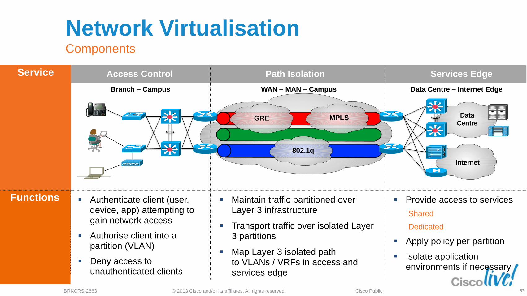
Network Virtualisation Components
Access Control Path Isolation Services Edge
WAN – MAN – Campus
Functions
Branch – Campus Data Centre – Internet Edge
VRFs
GRE MPLS
Authenticate client (user, device, app) attempting to gain network access
Authorise client into a partition (VLAN)
Deny access to unauthenticated clients
Maintain traffic partitioned over Layer 3 infrastructure
Transport traffic over isolated Layer 3 partitions
Map Layer 3 isolated path to VLANs / VRFs in access and services edge
Provide access to services
Shared
Dedicated
Apply policy per partition
Isolate application environments if necessary
Service
GRE MPLS
802.1q
Internet
Data
Centre
© 2013 Cisco and/or its affiliates. All rights reserved. BRKCRS-2663 Cisco Public 64
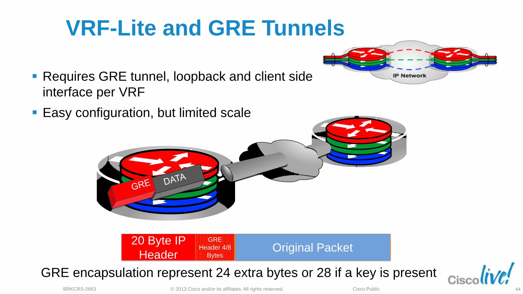
VRF-Lite and GRE Tunnels
GRE encapsulation represent 24 extra bytes or 28 if a key is present
20 Byte IP
Header
GRE
Header 4/8
Bytes Original Packet
Requires GRE tunnel, loopback and client side
interface per VRF
Easy configuration, but limited scale
© 2013 Cisco and/or its affiliates. All rights reserved. BRKCRS-2663 Cisco Public 65
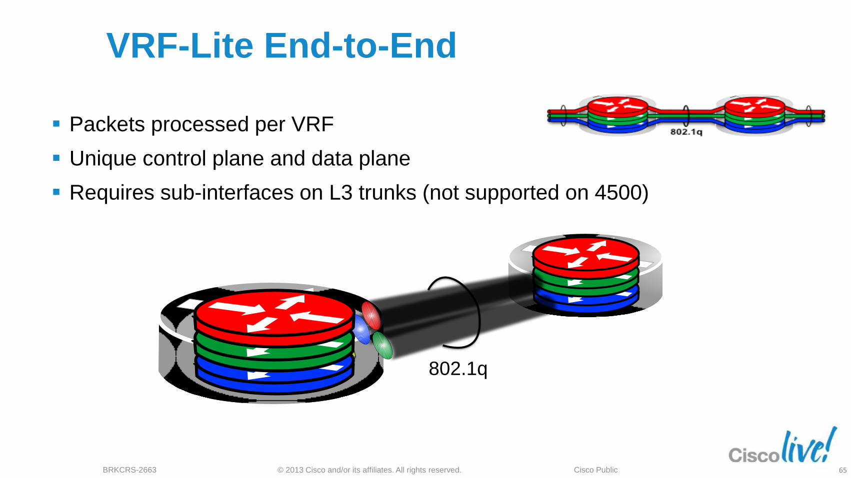
VRF-Lite End-to-End
802.1q
Packets processed per VRF
Unique control plane and data plane
Requires sub-interfaces on L3 trunks (not supported on 4500)
© 2013 Cisco and/or its affiliates. All rights reserved. BRKCRS-2663 Cisco Public 66
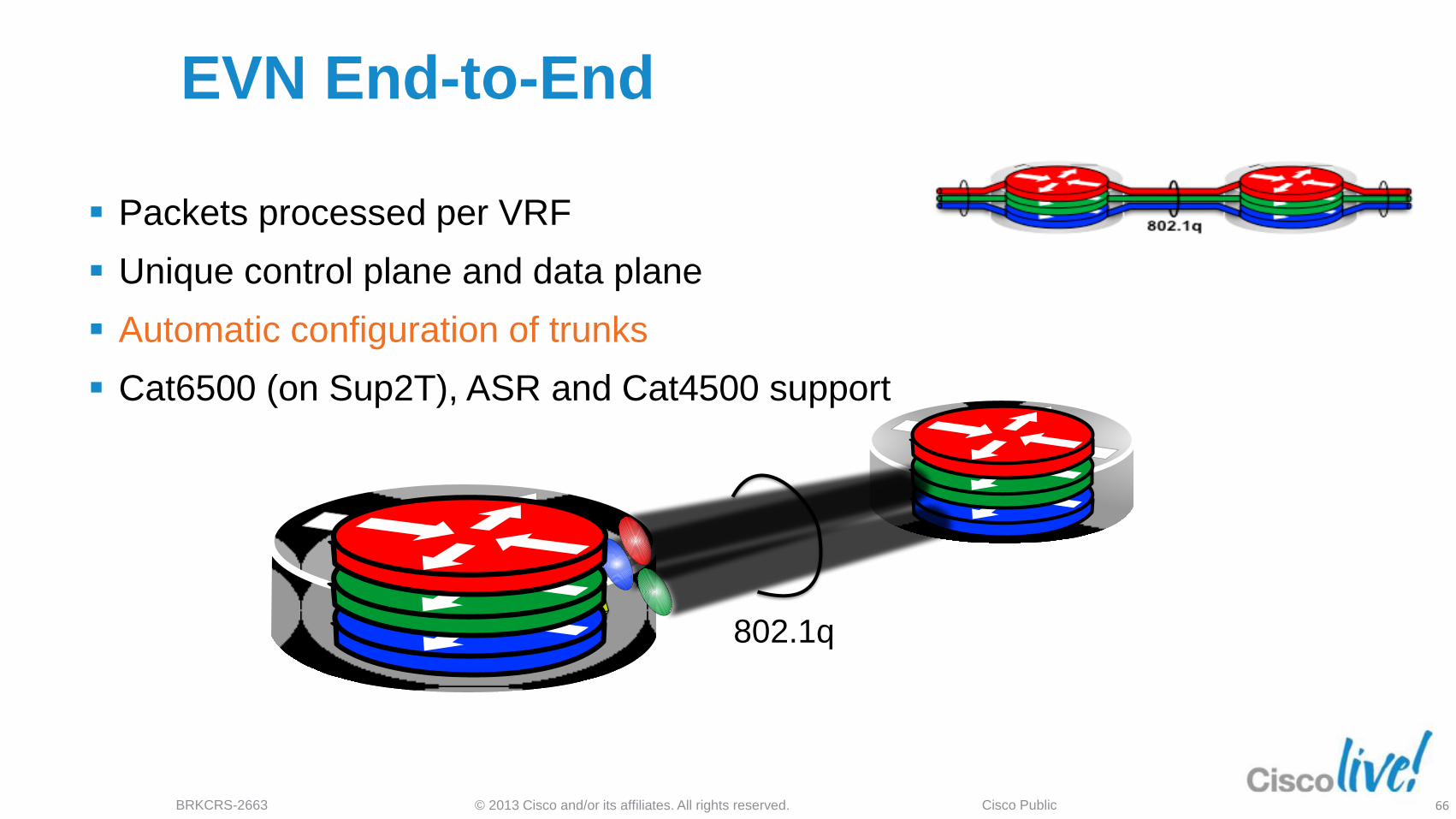
EVN End-to-End
802.1q
Packets processed per VRF
Unique control plane and data plane
Automatic configuration of trunks
Cat6500 (on Sup2T), ASR and Cat4500 support
© 2013 Cisco and/or its affiliates. All rights reserved. BRKCRS-2663 Cisco Public 67
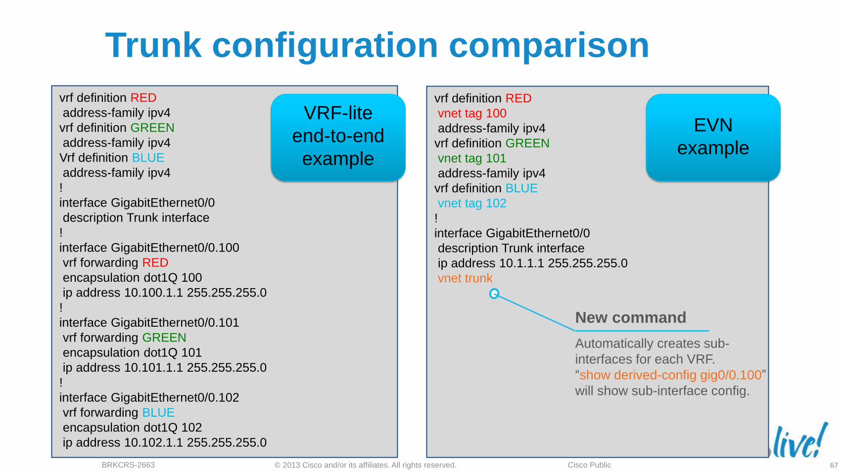
vrf definition RED
address-family ipv4
vrf definition GREEN
address-family ipv4
Vrf definition BLUE
address-family ipv4
!
interface GigabitEthernet0/0
description Trunk interface
!
interface GigabitEthernet0/0.100
vrf forwarding RED
encapsulation dot1Q 100
ip address 10.100.1.1 255.255.255.0
!
interface GigabitEthernet0/0.101
vrf forwarding GREEN
encapsulation dot1Q 101
ip address 10.101.1.1 255.255.255.0
!
interface GigabitEthernet0/0.102
vrf forwarding BLUE
encapsulation dot1Q 102
ip address 10.102.1.1 255.255.255.0
vrf definition RED
vnet tag 100
address-family ipv4
vrf definition GREEN
vnet tag 101
address-family ipv4
vrf definition BLUE
vnet tag 102
!
interface GigabitEthernet0/0
description Trunk interface
ip address 10.1.1.1 255.255.255.0
vnet trunk
Trunk configuration comparison
New command
Automatically creates sub-
interfaces for each VRF.
“show derived-config gig0/0.100”
will show sub-interface config.
VRF-lite
end-to-end
example
EVN
example

© 2013 Cisco and/or its affiliates. All rights reserved. BRKCRS-2663 Cisco Public 68
Virtualised network
Data Centre WAN Internet
SiSi SiSi SiSi SiSi SiSi SiSi
SiSi SiSi
SiSi SiSi
SiSi SiSi
SiSi SiSi
Access
Distribution
Core
Distribution
Access

© 2013 Cisco and/or its affiliates. All rights reserved. BRKCRS-2663 Cisco Public 69
Agenda
SiSiSiSi
SiSiSiSi
SiSi
Data Centre
SiSi SiSi
Services Block
Distribution Blocks
SiSi SiSi SiSi
Multilayer Campus
Design Principles
Foundation Services
Campus Design
Best Practices
Virtualisation techniques
Security considerations
What’s next….
Summary

© 2013 Cisco and/or its affiliates. All rights reserved. BRKCRS-2663 Cisco Public 70
WAN Internet
End-to-End Security
SiSi SiSi SiSi SiSi SiSi SiSi
SiSiSiSi
SiSiSiSi
SiSi SiSiSiSiSiSi
Best Practices—Campus Security
Things you already know… ‒ Use SSH to access devices instead of Telnet
‒ Enable AAA and roles-based access control (RADIUS/TACACS+) for the CLI on all devices
‒ Enable SYSLOG to a server. Collect and archive logs
‒ When using SNMP use SNMPv3
‒ Disable unused services:
No service tcp-small-servers No service udp-small-servers
‒ Use FTP or SFTP (SSH FTP) to move images and configurations around—avoid TFTP when possible
‒ Install VTY access-lists to limit which addresses can access management and CLI services
‒ Enable control plane protocol authentication where it is available (EIGRP, OSPF, BGP, HSRP, VTP, etc.)
For More Details, See BRKSEC-2202 Session, Understanding and Preventing Layer 2 Attacks

© 2013 Cisco and/or its affiliates. All rights reserved. BRKCRS-2663 Cisco Public 71
BPDU Guard
Problem:
‒ Users can plug a switch in at
their desk that tries to become
root
‒ Multiple Windows XP machines
can create a loop in the wired
VLAN via the WLAN
Solution:
‒ BPDU Guard configured on all
end-station switch ports will
prevent loop from forming Win XP
Bridging
Enabled
Win XP
Bridging
Enabled
BPDU Guard
Disables Port
STP Loop
Formed
BPDU
Generated
BPDU Guard
Disables Port
© 2013 Cisco and/or its affiliates. All rights reserved. BRKCRS-2663 Cisco Public 72
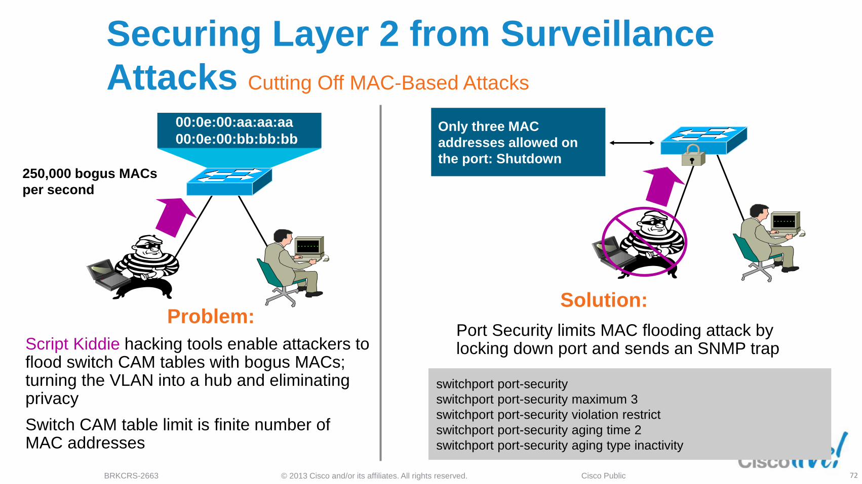
Port Security limits MAC flooding attack by locking down port and sends an SNMP trap
00:0e:00:aa:aa:aa
00:0e:00:bb:bb:bb
Script Kiddie hacking tools enable attackers to flood switch CAM tables with bogus MACs; turning the VLAN into a hub and eliminating privacy
Switch CAM table limit is finite number of MAC addresses
Only three MAC
addresses allowed on
the port: Shutdown 250,000 bogus MACs
per second
Problem: Solution:
switchport port-security
switchport port-security maximum 3
switchport port-security violation restrict
switchport port-security aging time 2
switchport port-security aging type inactivity
Securing Layer 2 from Surveillance
Attacks Cutting Off MAC-Based Attacks

© 2013 Cisco and/or its affiliates. All rights reserved. BRKCRS-2663 Cisco Public 73
DHCP Snooping Protection Against Rogue/Malicious DHCP Server
DHCP requests (discover) and responses (offer) tracked
Rate-limit requests on trusted interfaces; limits DoS attacks on DHCP server
Deny responses (offers) on non trusted interfaces; stop malicious or errant DHCP
server
DHCP
Server 1000s of DHCP requests to overrun the DHCP server
1
2
© 2013 Cisco and/or its affiliates. All rights reserved. BRKCRS-2663 Cisco Public 74
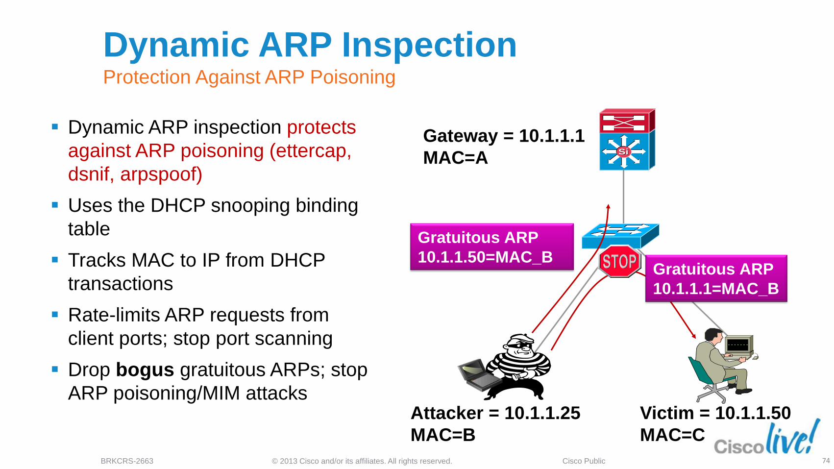
Dynamic ARP Inspection Protection Against ARP Poisoning
Dynamic ARP inspection protects
against ARP poisoning (ettercap,
dsnif, arpspoof)
Uses the DHCP snooping binding
table
Tracks MAC to IP from DHCP
transactions
Rate-limits ARP requests from
client ports; stop port scanning
Drop bogus gratuitous ARPs; stop
ARP poisoning/MIM attacks
SiSi
Gateway = 10.1.1.1
MAC=A
Attacker = 10.1.1.25
MAC=B
Victim = 10.1.1.50
MAC=C
Gratuitous ARP
10.1.1.1=MAC_B
Gratuitous ARP
10.1.1.50=MAC_B

© 2013 Cisco and/or its affiliates. All rights reserved. BRKCRS-2663 Cisco Public 75
IP Source Guard Protection Against Spoofed IP Addresses
IP source guard protects against
spoofed IP addresses
Uses the DHCP snooping binding
table
Tracks IP address to port
associations
Dynamically programs port ACL to
drop traffic not originating from
IP address assigned via DHCP
SiSi
Gateway = 10.1.1.1
MAC=A
Attacker = 10.1.1.25
Victim = 10.1.1.50
Hey, I’m 10.1.1.50 !
© 2013 Cisco and/or its affiliates. All rights reserved. BRKCRS-2663 Cisco Public 76
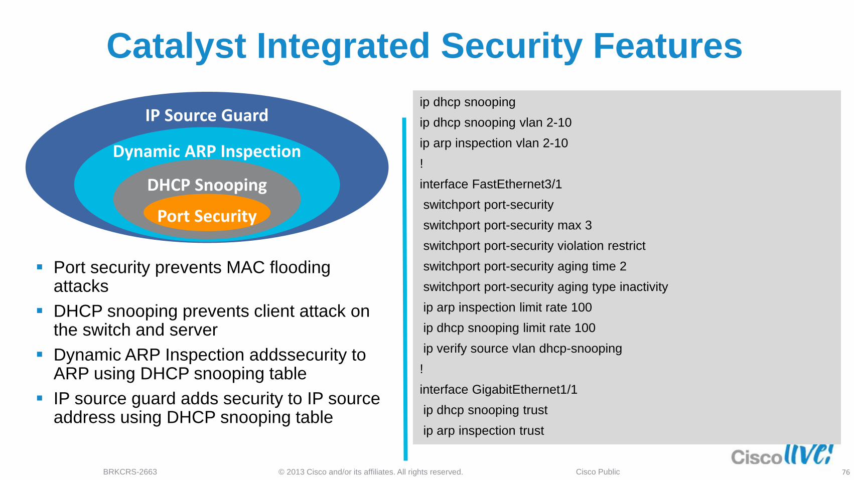
Catalyst Integrated Security Features
Port security prevents MAC flooding attacks
DHCP snooping prevents client attack on the switch and server
Dynamic ARP Inspection addssecurity to ARP using DHCP snooping table
IP source guard adds security to IP source address using DHCP snooping table
ip dhcp snooping
ip dhcp snooping vlan 2-10
ip arp inspection vlan 2-10
!
interface FastEthernet3/1
switchport port-security
switchport port-security max 3
switchport port-security violation restrict
switchport port-security aging time 2
switchport port-security aging type inactivity
ip arp inspection limit rate 100
ip dhcp snooping limit rate 100
ip verify source vlan dhcp-snooping
!
interface GigabitEthernet1/1
ip dhcp snooping trust
ip arp inspection trust
IP Source Guard
Dynamic ARP Inspection
DHCP Snooping
Port Security
© 2013 Cisco and/or its affiliates. All rights reserved. BRKCRS-2663 Cisco Public 77
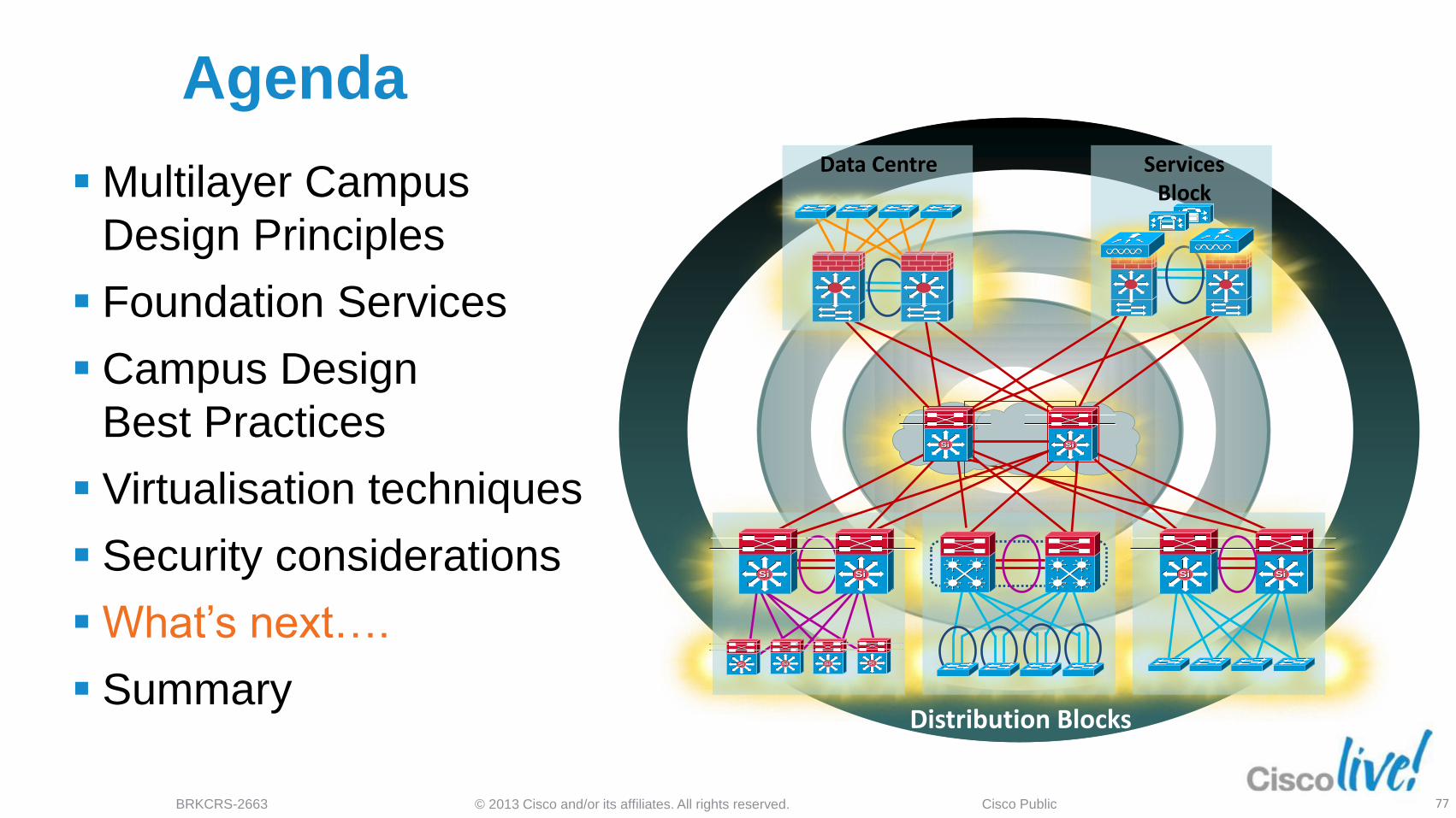
Agenda
Multilayer Campus
Design Principles
Foundation Services
Campus Design
Best Practices
Virtualisation techniques
Security considerations
What’s next….
Summary
SiSiSiSi
SiSiSiSi
SiSi
Data Centre
SiSi SiSi
Services Block
Distribution Blocks
SiSi SiSi SiSi

© 2013 Cisco and/or its affiliates. All rights reserved. BRKCRS-2663 Cisco Public 78
Reduction in Control Plane Less management points
VLAN 20 Data VLAN 40 Data
AN 40 Data 10.1.40.0/24
SiSi SiSi
VLAN 120 Voice 10.1.120.0/24 VLAN 140 Voice 10.1.140.0/24 VLAN 250 WLAN 10.1.250.0/24
VSS
VSS
Available now on 6500-E, 4500-X
and 4500-E
Useful in distribution layer

© 2013 Cisco and/or its affiliates. All rights reserved. BRKCRS-2663 Cisco Public 79
Reduction in Control Plane Less management points
VLAN 20 Data VLAN 40 Data
AN 40 Data 10.1.40.0/24
SiSi SiSi
VLAN 120 Voice 10.1.120.0/24 VLAN 140 Voice 10.1.140.0/24 VLAN 250 WLAN 10.1.250.0/24
VSS
VSS
Available now on 6500-E, 4500-X
and 4500-E
Useful in distribution layer
Smart Install
Zero-touch install of new devices
Automatic SW updates
Utilises DHCP to find new switches
Director
© 2013 Cisco and/or its affiliates. All rights reserved. BRKCRS-2663 Cisco Public 80
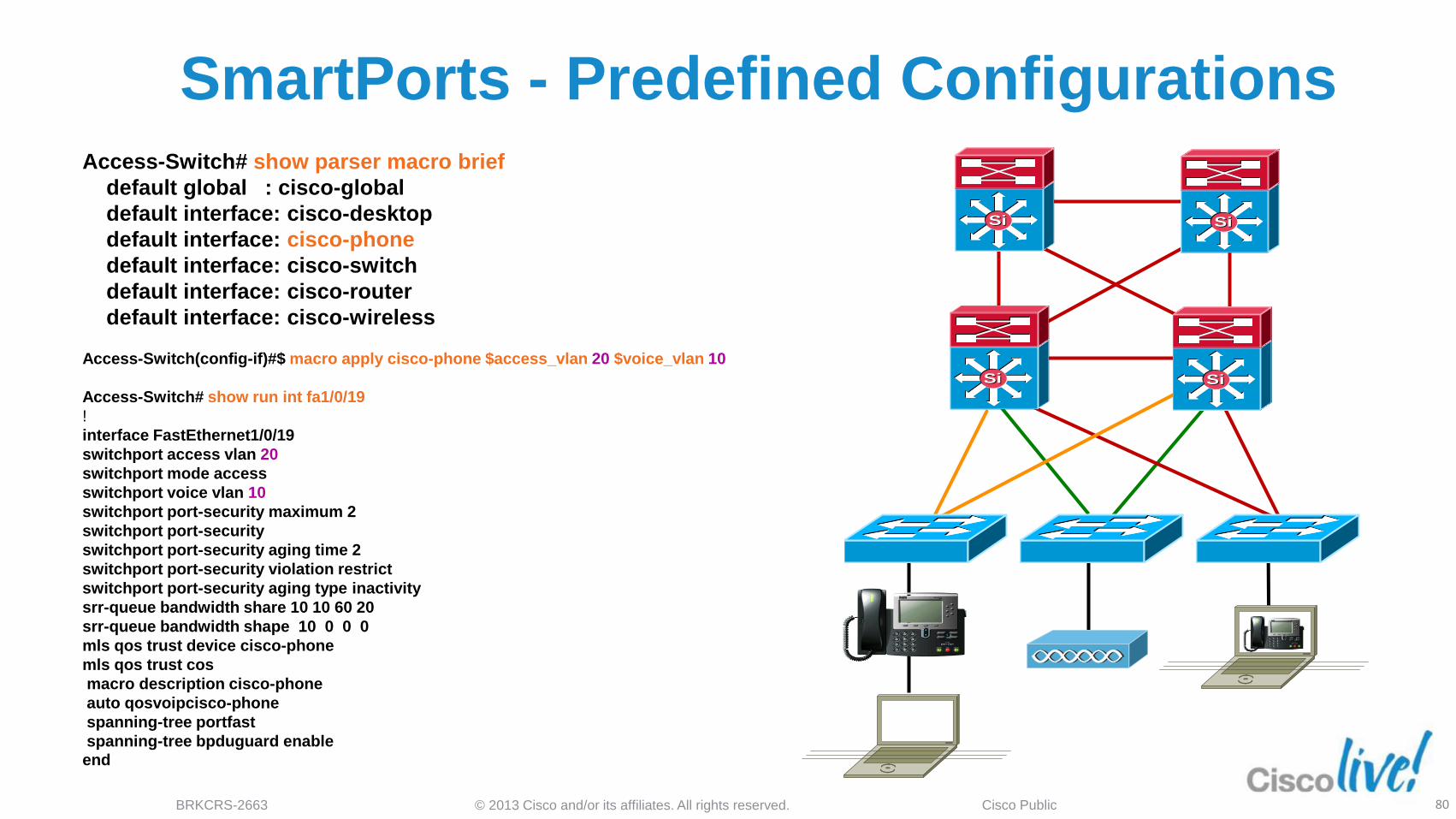
SmartPorts - Predefined Configurations
Access-Switch# show parser macro brief
default global : cisco-global
default interface: cisco-desktop
default interface: cisco-phone
default interface: cisco-switch
default interface: cisco-router
default interface: cisco-wireless
Access-Switch(config-if)#$ macro apply cisco-phone $access_vlan 20 $voice_vlan 10
Access-Switch# show run int fa1/0/19
!
interface FastEthernet1/0/19
switchport access vlan 20
switchport mode access
switchport voice vlan 10
switchport port-security maximum 2
switchport port-security
switchport port-security aging time 2
switchport port-security violation restrict
switchport port-security aging type inactivity
srr-queue bandwidth share 10 10 60 20
srr-queue bandwidth shape 10 0 0 0
mls qos trust device cisco-phone
mls qos trust cos
macro description cisco-phone
auto qosvoipcisco-phone
spanning-tree portfast
spanning-tree bpduguard enable end
SiSiSiSi
SiSi SiSi
© 2013 Cisco and/or its affiliates. All rights reserved. BRKCRS-2663 Cisco Public 81
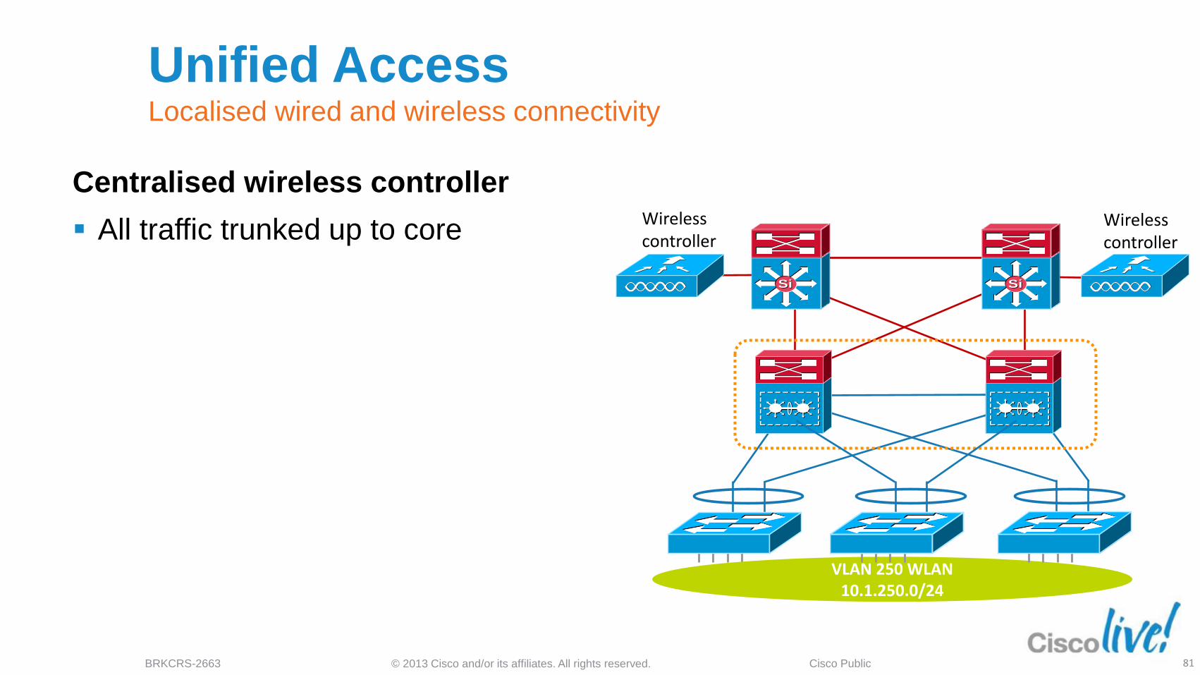
Unified Access Localised wired and wireless connectivity
SiSi SiSi
VLAN 250 WLAN 10.1.250.0/24
Centralised wireless controller
All traffic trunked up to core
Wireless controller
Wireless controller
© 2013 Cisco and/or its affiliates. All rights reserved. BRKCRS-2663 Cisco Public 82
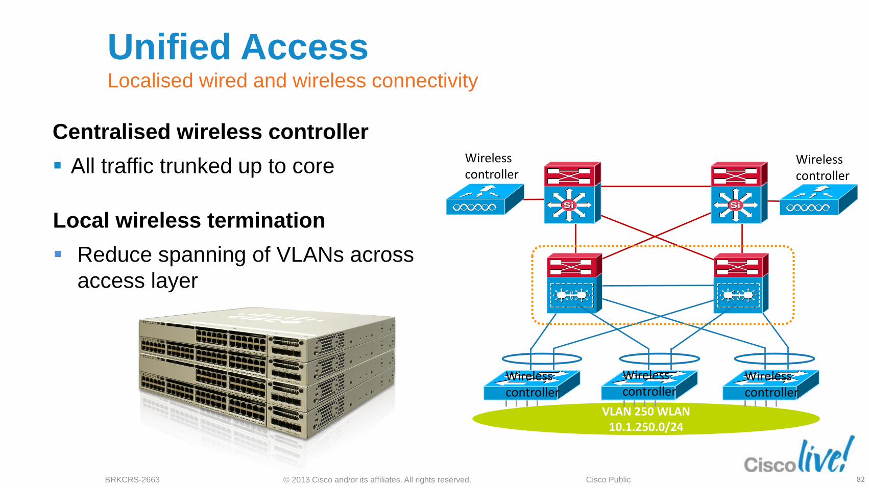
Unified Access Localised wired and wireless connectivity
SiSi SiSi
VLAN 250 WLAN 10.1.250.0/24
Centralised wireless controller
All traffic trunked up to core
Wireless controller
Wireless controller
Wireless controller
Wireless controller
Wireless controller
Local wireless termination
Reduce spanning of VLANs across
access layer

© 2013 Cisco and/or its affiliates. All rights reserved. BRKCRS-2663 Cisco Public 83
Unified Access Localised wired and wireless connectivity
SiSi SiSi
Centralised wireless controller
All traffic trunked up to core
Wireless controller
Wireless controller
Wireless controller
Local wireless termination
Reduce spanning of VLANs across
access layer
Wireless
VLAN 100 Wireless
VLAN 110
Wireless
VLAN 120
L3
© 2013 Cisco and/or its affiliates. All rights reserved. BRKCRS-2663 Cisco Public 84
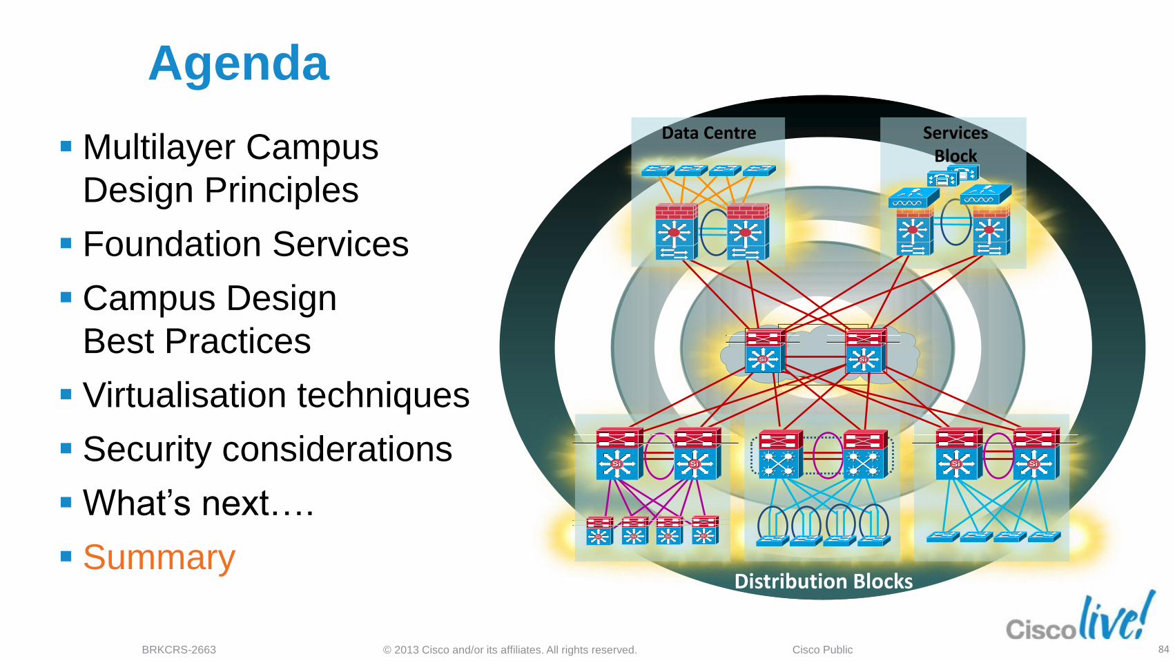
Agenda
SiSiSiSi
SiSiSiSi
SiSi
Data Centre
SiSi SiSi
Services Block
Distribution Blocks
SiSi SiSi SiSi
Multilayer Campus
Design Principles
Foundation Services
Campus Design
Best Practices
Virtualisation techniques
Security considerations
What’s next….
Summary
© 2013 Cisco and/or its affiliates. All rights reserved. BRKCRS-2663 Cisco Public 85
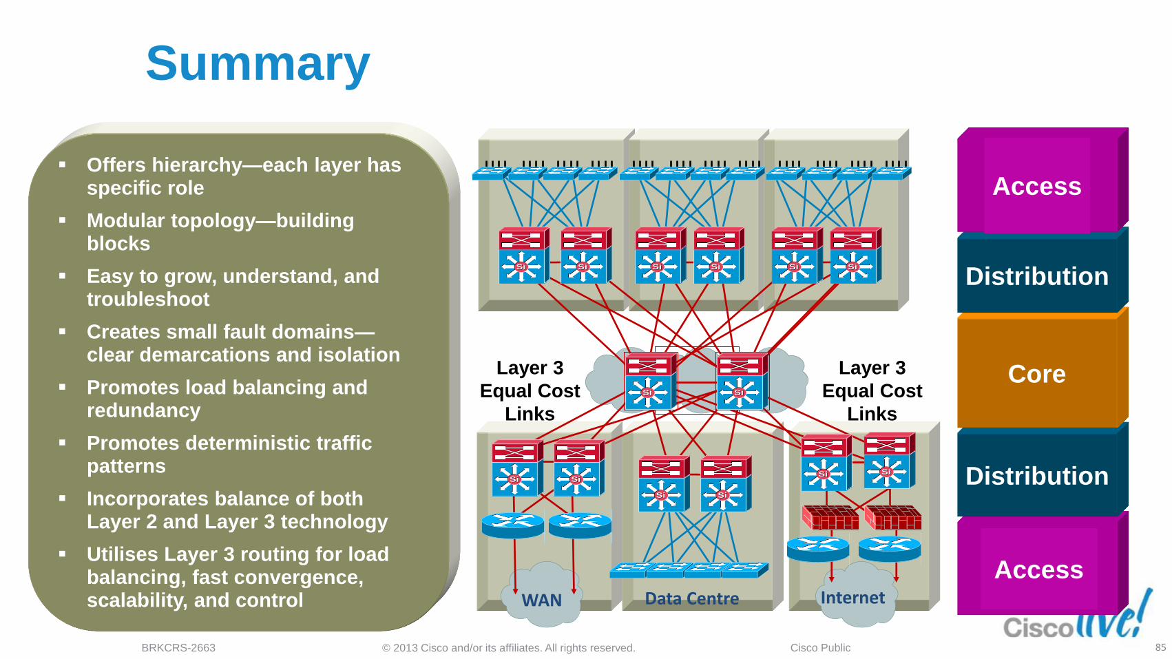
Summary
Offers hierarchy—each layer has specific role
Modular topology— building blocks
Easy to grow, understand, and troubleshoot
Creates small fault domains— Clear demarcations and isolation
Promotes load balancing and redundancy
Promotes deterministic traffic patterns
Incorporates balance of both Layer 2 and Layer 3 technology, leveraging the strength of both
Utilises Layer 3 routing for load balancing, fast convergence, scalability, and control
Data Centre WAN Internet
Layer 3
Equal Cost
Links
Layer 3
Equal Cost
Links
Access
Distribution
Core
Distribution
Access
SiSi SiSi SiSi SiSi SiSi SiSi
SiSi SiSi
SiSi SiSi
SiSi SiSi
SiSi SiSi
Offers hierarchy—each layer has specific role
Modular topology—building blocks
Easy to grow, understand, and troubleshoot
Creates small fault domains— clear demarcations and isolation
Promotes load balancing and redundancy
Promotes deterministic traffic patterns
Incorporates balance of both Layer 2 and Layer 3 technology
Utilises Layer 3 routing for load balancing, fast convergence, scalability, and control

© 2013 Cisco and/or its affiliates. All rights reserved. BRKCRS-2663 Cisco Public 86
Hierarchical Network Design Without a Rock Solid Foundation the Rest Doesn’t Matter
Spanning
Tree Routing
HSRP
Access
Distribution
Core
Distribution
Access
Building Block
SiSi SiSi
SiSi SiSi
SiSi SiSi
Q & A
© 2013 Cisco and/or its affiliates. All rights reserved. BRKCRS-2663 Cisco Public
Complete Your Online Session
Evaluation
Give us your feedback and receive
a Cisco Live 2013 Polo Shirt!
Complete your Overall Event Survey and 5
Session Evaluations.
Directly from your mobile device on the
Cisco Live Mobile App
By visiting the Cisco Live Mobile Site
www.ciscoliveaustralia.com/mobile
Visit any Cisco Live Internet Station located
throughout the venue
Polo Shirts can be collected in the World of
Solutions on Friday 8 March 12:00pm-2:00pm
Don’t forget to activate your
Cisco Live 365 account for
access to all session material,
88
communities, and on-demand and live activities throughout
the year. Log into your Cisco Live portal and click the
"Enter Cisco Live 365" button.
www.ciscoliveaustralia.com/portal/login.ww
© 2013 Cisco and/or its affiliates. All rights reserved. BRKCRS-2663 Cisco Public


