
June 2010 Corporate Planning and Monitoring Cell 1
Next Generation Aggregation Transport Network
With End-to-End MPLS support
- A build and migrate strategy specifying deliverables
1. Introduction:
The Next Generation Transport Network shall be designed to provide Next
Generation Transport for all network services including residential multi play
services such as Video on Demand, Video Multi cast, Voice, High Speed
Internet, business services such as PDH leased lines, SDH leased lines, Ethernet
leased line, layer 2 VPN and layer 3 VPN, and backhauling of 2G, 3G and 4G
mobile traffic, with guaranteed control over critical parameters like latency,
jitter and throughput to ensure high grade delivery of real time service, near
real time service and best effort service over any access line such as Digital
Subscriber Line (DSL), Wireless Local Area Network (WLAN), Fibre To The
Home-Gigabit Passive Optical Network (FTTH-GPON) lines, PDH access lines
(E1), SDH access lines (STM-1, STM-4, STM-16), and 2G, 3G and 4G Radio
Access Networks (RAN).
The Transport network is segregated into a Core Layer-3 IP-MPLS based
network and an Aggregation Layer-2 Ethernet based Access network
terminated at the IP-MPLS Edge node. An aggregation network as the name
suggests, aggregates traffic over an area of say 20 km radius through a three
tier architecture. The Hub of the aggregation network, called the Central Office
Aggregation Unit (COAU) is collocated with the Next Generation Central Office
(NG-CO) which houses the national level IP-MPLS Edge node. The COAU
consists of the Tier-1 Carrier Ethernet (CE) switch which will handle traffic from
erstwhile STM-16 rings as well as the Multiplay 10GE rings and new
10GE/100GE RPR rings. The DWDM core is used to interconnect IP-MPLS core
nodes, as well as directly interconnecting COAU Tier I switches / L2PE in case
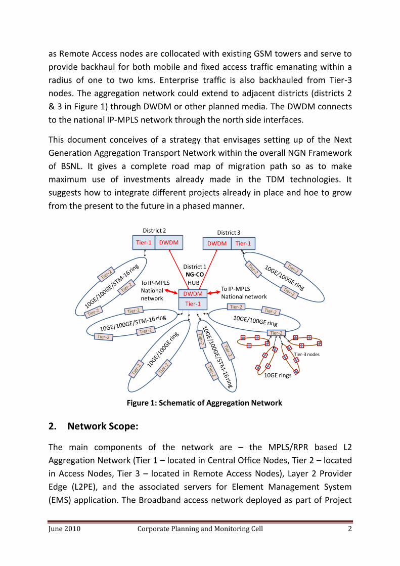
collocation is not possible. The aggregation network is architected in three
tiers as indicated in the schematic in Figure 1.
Tier-2 nodes are located in erstwhile TDM exchange buildings which are re-
designated as Next Generation Access Nodes (NG-AN). Tier-3 nodes designated
June 2010 Corporate Planning and Monitoring Cell 2
as Remote Access nodes are collocated with existing GSM towers and serve to
provide backhaul for both mobile and fixed access traffic emanating within a
radius of one to two kms. Enterprise traffic is also backhauled from Tier-3
nodes. The aggregation network could extend to adjacent districts (districts 2
& 3 in Figure 1) through DWDM or other planned media. The DWDM connects
to the national IP-MPLS network through the north side interfaces.
This document conceives of a strategy that envisages setting up of the Next
Generation Aggregation Transport Network within the overall NGN Framework
of BSNL. It gives a complete road map of migration path so as to make
maximum use of investments already made in the TDM technologies. It
suggests how to integrate different projects already in place and hoe to grow
from the present to the future in a phased manner.
That
2. Network Scope:
The main components of the network are – the MPLS/RPR based L2
Aggregation Network (Tier 1 – located in Central Office Nodes, Tier 2 – located
in Access Nodes, Tier 3 – located in Remote Access Nodes), Layer 2 Provider
Edge (L2PE), and the associated servers for Element Management System
(EMS) application. The Broadband access network deployed as part of Project
DWDM
Tier-1
Tier-2
Tier-2
10GE rings
Tier-3 nodes
DWDMTier-1 DWDM Tier-1
HUB
District 1NG-CO
District 2 District 3
Figure 1: Schematic of Aggregation Network
To IP-MPLSNational network
To IP-MPLSNationalnetwork

June 2010 Corporate Planning and Monitoring Cell 3
2.2 of NIB-II, Broadband Multi Play phases 1, 2, 3, and GPON Next Generation
Play will also be integrated with the Next Generation Transport Network
deployed through this project. This network shall also be integrated with the
existing BNG and nationwide MPLS core network.
3. Objectives:
BSNL’s primary objectives in setting up the Next Generation Transport Network are:
3.1 Convergence of all network services under a unified transport infrastructure, instead of the existing multiple transport networks for the various network services and access technologies.
3.2 Transporting of all network services, including the emerging packet-based services, and the legacy Time Division Multiplexing (TDM) services, over Layer 2 MPLS.
3.3 The solution shall provide sub-50ms protection time against link failures in transport rings, using RPR.
3.4 Efficient Video Multi cast distribution in transport rings, using RPR.
3.5 Significant reduction in the power consumption of the transport network, in order to minimize the electricity expenses which are a significant portion of BSNL’s Operational Expenses (OPEX).
3.6 The solution shall allow for smooth migration from the existing BSNL transport network to the Next Generation Transport network, leveraging the installed base of BSNL.
3.7 The solution shall provide standardized prioritization of different classes of traffic in terms of treatment of packets with regard to latency, jitter, delivery and committed throughput in order to effectively handle the diverse requirement of real time traffic, near real time traffic, and best effort traffic.
3.8 The solution shall provide effective delivery of real time applications like multicast video services, video-on-demand, video conferencing, VoIP etc through guaranteed end-to-end quality of service driven by end-to-end MPLS support.
3.9 The solution shall provide transport for various Layer 2 VPN and Layer 3 VPN services (where Layer 3 functionality shall be provided by the L3PE, which is part of the existing IP-MPLS national network).

June 2010 Corporate Planning and Monitoring Cell 4
3.10 The solution shall be used for high speed Internet connectivity and shall be the primary source of Internet bandwidth for users for applications such as web browsing, e-Commerce, etc
3.11 The solution shall be used for connecting dial VPN customers to the MPLS VPN through the Narrowband RAS.
3.12 The solution shall be used for converged backhauling of 2G, 3G, and 4G mobile traffic as well as fixed broadband traffic of DSL, PON, etc.
3.13 The solution shall interface to the existing BNG and nationwide MPLS core network.
3.14 The solution will also integrate the broadband access network already deployed as part of Project 2.2 of NIB-II, Broadband Multi Play phases 1, 2, 3, and Next Generation Play GPON networks.
4. Planning guidelines for Broadband Network Architecture:
4.1 Existing access networks such as Digital Subscriber Line (DSL), Wireless Local Area Network (WLAN), Fibre To The Home-Gigabit Passive Optical Network (FTTH-GPON) lines, PDH access lines (E1), SDH access lines (STM-1, STM-4, STM-16), and 2G, 3G and 4G Radio Access Networks (RAN), shall be aggregated through the Next Generation Transport Network.
4.2 An aggregation unit utilizing MPLS/RPR/10GE shall be planned for around 40 thousand users.
4.3 An aggregation unit utilizing MPLS/RPR/100GE shall be planned for around 256 thousand users.
4.4 Traffic of such aggregation units shall be handed over to the backbone MPLS core directly.
4.5 For establishing the Next Generation Transport Network, MPLS over RPR based layer 2 switches shall be deployed. The LAN Switch equipment shall support the IEEE 802.3ad Ethernet Link aggregation technology.
4.6 The Next Generation Transport Network shall consist of multiple aggregation points, which will aggregate the broadband traffic spread over the country. The Aggregation points are likely to be collocated with the MPLS edge connected through multiple GE and 10GE interfaces.
June 2010 Corporate Planning and Monitoring Cell 5
4.7 The Next Generation Transport Network shall be deployed in the following phases:
4.7.1 The switches deployed as part of the GPON Next Generation Play network shall be Tier 2 MPLS/RPR/10GE switches, as well as Tier 1 MPLS/RPR/10GE switches. The Tier 1 switches deployed in this phase shall also perform the function of a Layer 2 Provider Edge (L2PE).
4.7.2 The switches deployed as part of the Multiplay phase 3 network shall be Tier 2 MPLS/RPR/10GE switches, as well as Tier 1 MPLS/RPR/10GE switches. The Tier 1 switches deployed in this phase shall also perform the function of a Layer 2 Provider Edge (L2PE).
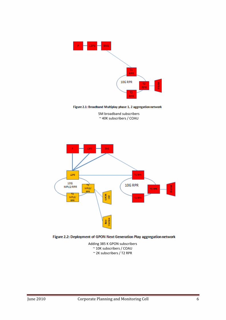
4.7.3 The switches deployed as part of the revised STM-64 tender shall be Tier 3 MPLS/RPR/10GE switches. Part of these switches shall connect to existing 10G RPR switches deployed as part of Multiplay phase 1 and 2 network. Another part of these switches shall connect to MPLS/RPR/10GE switches deployed as part of the GPON Next Generation Play network and Multiplay phase 3 network.
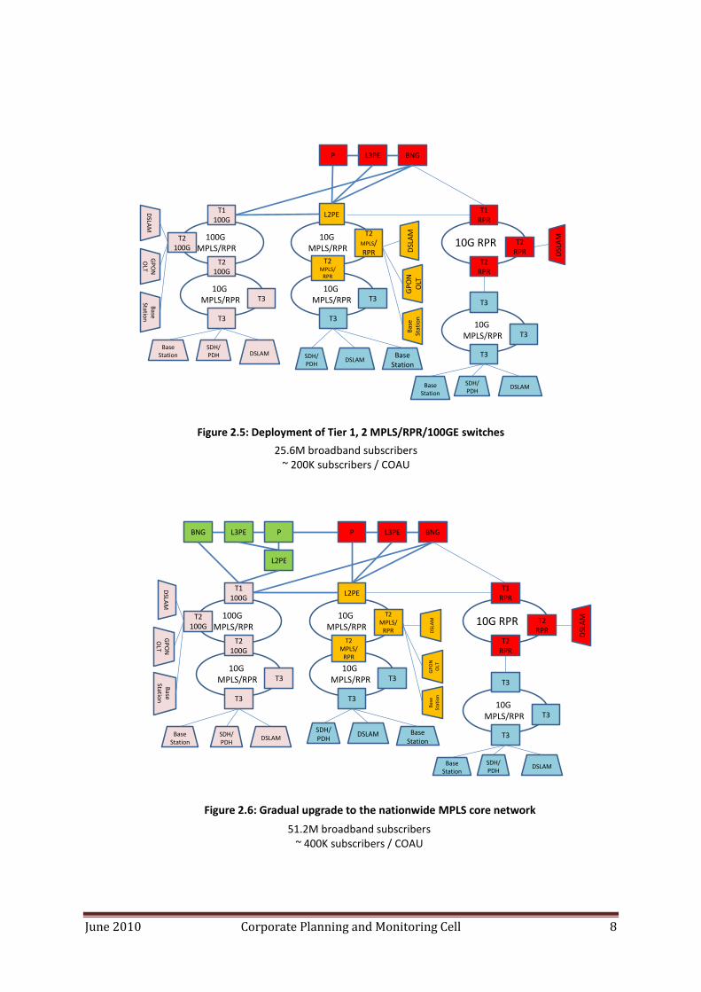
4.7.4 The switches deployed as part of the NGN phase 1 and phase 2 networks shall be Tier 1 and Tier 2 MPLS/RPR/100GE switches, and Tier 3 MPLS/RPR/10GE switches. These switches shall be connected to the existing nationwide MPLS core network and BNG, as well as to the L2PE deployed as part of the GPON Next Generation Play network and Multiplay phase 3 network.
4.7.5 The subscriber target for the NGN phase 1 and phase 2 networks shall require gradual upgrade of the switching capacity of the nationwide MPLS core network and BNG. Such upgrade is however outside the scope of this document. However, the aggregation network is designed with such upgrade in mind, with regards to the switching capacity of the MPLS/RPR switches and the L2PE, their ring interface, their interfaces to the BNG, L3PE and P routers, and their scalability requirements.
5. Broadband Network Growth and Migration strategy:
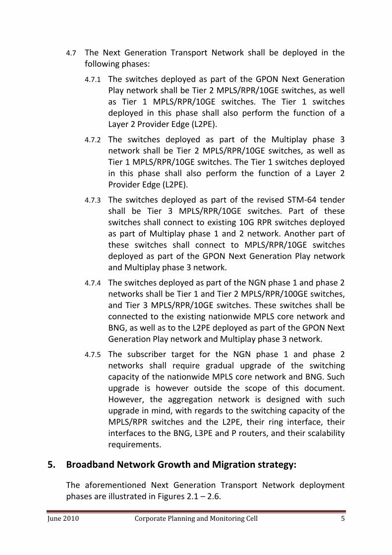
The aforementioned Next Generation Transport Network deployment phases are illustrated in Figures 2.1 – 2.6.
June 2010 Corporate Planning and Monitoring Cell 6
5M broadband subscribers ~ 40K subscribers / COAU
Adding 385 K GPON subscribers ~ 10K subscribers / COAU ~ 2K subscribers / T2 RPR
June 2010 Corporate Planning and Monitoring Cell 7
10M broadband subscribers ~ 40K subscribers / COAU ~8K subscribers / T2 RPR
STM-64 tender modified to fit 3 tier NGN transport framework
~ 100K subscribers / COAU
June 2010 Corporate Planning and Monitoring Cell 8
P L3PE BNG
T1 RPR
T2 RPR
T2 RPR
L2PE
T2MPLS/RPR
T3
DSLAMSDH/PDH
T3
T3
DSL
AM
DSLAMSDH/PDH
T3
T3
T2MPLS/
RPR
T1100G
T2 100G
DSLA
MG
PO
N
OLT
DSLAMSDH/PDH
T3
T3
T2 100G
10G RPR
10G MPLS/RPR
10G MPLS/RPR
10G MPLS/RPR
100G MPLS/RPR
10G MPLS/RPR
DSL
AM
GP
ON
O
LT
BaseStation
BaseStation
BaseStation
Base
Station
Bas
e St
atio
n
Figure 2.5: Deployment of Tier 1, 2 MPLS/RPR/100GE switches
P L3PE BNG
T1 RPR
T2 RPR
T2 RPR
L2PE
T2MPLS/
RPR
T3
DSLAMSDH/PDH
T3
T3
DSL
AM
DSLAMSDH/PDH
T3
T3
T2MPLS/
RPR
T1100G
T2 100G
DSLA
MG
PO
N
OLT
DSLAMSDH/PDH
T3
T3
T2 100G
10G RPR
10G MPLS/RPR
10G MPLS/RPR
10G MPLS/RPR
100G MPLS/RPR
10G MPLS/RPR
BNG L3PE P
L2PE
DSL
AM
GP
ON
O
LT
BaseStation
BaseStation
BaseStation
Base
Station
Bas
e St
atio
n
Figure 2.6: Gradual upgrade to the nationwide MPLS core network
25.6M broadband subscribers ~ 200K subscribers / COAU
51.2M broadband subscribers ~ 400K subscribers / COAU
June 2010 Corporate Planning and Monitoring Cell 9
5.1 The aforementioned phased approach achieves the goal of smooth
migration from the existing BSNL transport network to the Next
Generation Transport network, leveraging the installed base of BSNL.
5.2 The network will be centrally managed from the Network Operation
Centre (NOC) deployed under NIB-II and also from the Element
Management System client located within the same city. The main
NOC is at Bangalore with provision of D/R NOC at Pune. The element
Management System (EMS) applications procured in this project
shall be integrated with the HP’s Network Management System
(NMS) application (HP Open View) on standard northbound interface
such as SNMP, Java API, CORBA API, or XML API. FTP or TFTP shall be
used for bulk file transfer.
5.3 The Provisioning in Next Generation play solution shall be done both
centrally and distributed manner using an ASAP application. The
required cartridges for integrating the different elements of Next
Generation Transport need to be provided for in the project
deliverables for ensuring end-to-end provisioning in Next Generation
Network. The provisioning in NIB-II MPLS network shall continue to
be handled with the existing provisioning system (HPOVSA).
5.4 The back-office facility (such as AAA, LDAP, Billing and Provisioning
and NMS servers) is located in the NOC at Pune and Bangalore
procured in NIB-II and the same infrastructure will be leveraged for
the Next Generation Transport network.
6. Service Deliverables:
Following services, with and without SLA guarantee, shall be transported
over MPLS/RPR transport infrastructure.
6.1 Residential services:
6.1.1 Basic Internet Access Service (controlled and uncontrolled): speed
ranging from 256 kbps to 1000 Mbps.
6.1.2 TV over IP Service: It facilitates distribution of broadcast TV
channels in digital mode (MPEG2/MPEG4/H.264) on the
broadband network to the customer and is converted back to an
June 2010 Corporate Planning and Monitoring Cell 10
analog format in the home for reception on a standard television
set.
6.1.3 Video on Demand Service (VoD): It provides users with the ability
to select video content (MPEG2/MPEG4/H.264) (usually a movie
from a library) and view it at their convenience. The user can
pause, go backward, forward and repeat the content as per their
desire. It is similar to a video tape being played from VCR except
that the content is delivered via a content server which can be
located at any point of the network, instead of from a VCR.
6.1.4 Audio on Demand Service: The mechanism is as explained in above
except for the content. In place of video, it is the audio file which
the user selects.
6.1.5 Bandwidth on Demand: User configurable and Service
configurable.
6.1.6 Point to point and point to multi point Video Conferencing: It
permits users to establish point-to-point connections between
their PCs/H.323/SIP terminals and allow them to see and hear
each other as well as share PC data / applications.
6.1.7 Remote Education: It combines both Video conferencing and the
2-way interactive data capabilities of the broadband network to
create a virtual classroom where students participate remotely
with an instructor in a way that mimics a regular class.
6.1.8 Voice and Video Telephony over IP: Allows H.323/ SIP terminals to
set up point to point connections under control of centrally
located soft switches.
6.1.9 Interactive gaming: both single user and multi user shall be
supported.
6.2 Enterprise services:
6.2.1 E1 leased lines (delivered either on a physical E1 interface or
groomed over channelized STM-1/4 interfaces) as per SAToP (RFC
4553).
6.2.2 STM-1/STM-4/STM-16 leased lines as per CEP (RFC 4842).
6.2.3 It shall be possible to provide Circuit Emulation Services at VC-12
and VC-4/4c granularity.
June 2010 Corporate Planning and Monitoring Cell 11
6.2.4 The E1 grooming to STM-1/4 ports shall be non-blocking.
6.2.5 Circuit Emulation Services shall be non-blocking.
6.2.6 Port based, Virtual LAN (VLAN) based, port + VLAN based and port
+ VLAN range based Ethernet services as per following:
6.2.6.1 Enterprise customers shall be connected using a
universal FE/GE port. Such port can connect to
customer’s FE port if the customer equipment does not
support GE, but on the other hand can configure to GE
using software configuration (remotely from EMS). This
way, an enterprise customer can be upgraded from a
100Mbps service to 200Mbps service to 1000Mbps
service without change of hardware. This means that the
purchased equipment shall not have different line cards
for FE and GE, but rather one line card which can support
FE and GE with per-port software configuration. This
approach is taken today by most operators worldwide.
6.2.6.2 Large enterprise customers shall optionally be connected
using 10GE interfaces.
6.2.6.3 Point-to-Point Ethernet Service: Ethernet Private Line
(EPL) and Ethernet Virtual Private Line (EVPL) as per
Technical Specification MEF-6 of Metro Ethernet Forum
(MEF).
6.2.6.4 Multipoint-to-Multipoint Ethernet services: Ethernet LAN
(E-LAN) as per Technical Specification MEF-6 of MEF.
6.2.6.5 Ethernet Virtual Leased Line (VLL): Solution shall support
the VLL implementation with the following RFCs:
i. RFC 3985 Pseudo Wire Emulation Edge-to-Edge (PWE3)
ii. RFC 4385 Pseudo Wire Emulation Edge-to-Edge (PWE3) Control Word for Use over an MPLS PSN
iii. RFC 3916 Requirements for Pseudo- Wire Emulation Edge-to-Edge (PWE3)

June 2010 Corporate Planning and Monitoring Cell 12
iv. RFC 4448 Encapsulation Methods for Transport of Ethernet over MPLS Networks RFC 4446 IANA Allocations for PWE3
6.2.6.6 Differentiated priority access service as per following:
(i) Configurable priority per customer.
(ii) Application Recognition and priority for separate
applications for one customer shall also be
configurable.
6.2.6.7 Differentiated bandwidth access service as per following:
(i) Configurable bandwidth per customer.
(ii) Dedicated bandwidth per customer via Committed Information Rate (CIR) and Excess Information Rate (EIR.
(iii) Range of configurable rates from kbps to Gbps (depending on the access mechanism allowances)
6.2.6.8 The Differentiated Services model shall be implemented
in compliance with RFC 2474, RFC 2597, RFC 3140 and
RCF 3246.
6.2.7 Layer 3 VPN as per RFC 2457 bis/ Layer 2 VPN Service: It allows
customers to connect their offices together over a public
infrastructure with service similar to the leased line based
Private WAN. The solution shall provide layer 2 transport for
various Layer 2 VPN and Layer 3 VPN services (where Layer 3
functionality shall be provided by the L3PE, which is part of the
existing IP-MPLS national network)
6.2.8 VPN on broadband: It facilitates access of VPN on broadband
access lines.
6.2.9 Dial up VPN Service: It facilitates access of VPN through dial up
line (PSTN / ISDN). This is used for accessing the VPN from
remote site or for using backup of leased VPN.
6.3 Backhaul Services:
6.3.1 Backhauling of E1 lines from 2G BTS or from last mile PDH
microwave equipment to 2G BSC as per SAToP (RFC 4553).

June 2010 Corporate Planning and Monitoring Cell 13
6.3.2 Backhauling of STM-1/STM-4/STM-16 traffic from SDH
microwave equipment to 2G BSC as per CEP (RFC 4842).
6.3.3 Backhauling of Ethernet traffic from 3G NodeB, last mile
Ethernet microwave equipment, WiMax base stations and LTE
eNodeB to 3G RNC, Wimax ASN GW and 4G aGW and S-GW at
Remote Access Nodes.
6.3.4 Backhauling of Ethernet traffic from DSLAMs, PON and OLTE at
Remote Access Nodes.
7. Solution Deliverables:
The solution shall provide any Ethernet service on any Ethernet port and any TDM service on any TDM port connected to the Tier 1, Tier 2, and Tier 3 switches. Ethernet traffic shall be prioritized by the access equipment for upside and by Broadband Network Gateway (BNG) or L3PE for down side. TDM traffic shall be encapsulated into circuit emulation packets by the Tier 1, Tier 2, and Tier 3 switches, and shall be given strict priority over non-real-time Ethernet traffic. This priority shall be carried across the network by one to one mapping of IEEE 802.1p bits/ Type of Service (ToS) bits to MPLS EXP bits and vice versa.
7.1 Interface requirements:
The connectivity of different solution components shall be over FE/ GE/ 10 GE interface. Solution shall consist of Central Office Aggregation Units (COAU) and their EMS applications.
7.2 Access Nodes interfacing the Next Generation Transport network:
7.2.1 The access nodes listed in this section do not form part of this project. However, the interfaces required in the Tier 1, Tier 2, and Tier 3 switches towards these access nodes shall be within the scope of deliverables.
7.2.2 DSLAM / MSAN shall in general be collocated with existing PSTN exchanges, which provide first mile access to customers over fibre up to average span lengths of 4 kms.
June 2010 Corporate Planning and Monitoring Cell 14
7.2.3 GPON OLT shall in general be collocated with existing PSTN exchanges, which provide first mile access to customers over fibre up to average span lengths of 20 kms.
7.2.4 DSLAMs, MSANs and GPON OLTs will be aggregated through multiple 10GbE and Gigabit Ethernet (GE) interfaces with redundancy, using link aggregation fashion, to the same Tier 1 / Tier 2 / Tier 3 switch on different paths.
7.2.5 The DSLAMs, MSANs and GPON OLTs are capable of adding single/dual VLAN tags.
7.2.6 PDH access equipment, mobile base stations with PDH interfaces, and last mile PDH microwave equipment, shall connect to the Tier 3 switches using E1 interfaces.
7.2.7 SDH access equipment, and last mile SDH microwave equipment, will be aggregated through multiple STM-1, STM-4, and STM-16 interfaces with redundancy, using MSP 1+1, to the same Tier 1 / Tier 2 / Tier 3 switch on different paths.
7.3 Service Edge Nodes interfacing Next Generation Transport network:
7.3.1 The service edge nodes (BNG, L3PE, TDM cross connect and mobile gateways), listed in this section do not form part of the aggregation network. However, the interfaces required in the L2PE switches towards these service edge nodes shall be within the scope of deliverables.
7.3.2 Residential services shall be terminated in a BNG through multiple 10GbE and Gigabit Ethernet (GE) interfaces with redundancy, using link aggregation fashion, to the L2PE switch. For optional node-level redundancy, dual homing of one or two L2PE switches to the one or two BNG shall be supported.
7.3.3 Business Layer 3 VPN services and internet access services shall be terminated in a L3PE through multiple 10GbE and Gigabit Ethernet (GE) interfaces with redundancy, using link aggregation fashion, to the L2PE switch. For optional node-level redundancy, dual homing of one or two L2PE switches to the one or two L3PE shall be supported.
7.3.4 TDM leased line services shall be initially terminated at existing TDM cross-connects, through multiple STM-1, STM-4, and STM-16 interfaces with redundancy, using MSP 1+1, to the
June 2010 Corporate Planning and Monitoring Cell 15
L2PE. Over time, it is expected that most TDM services will be fully migrated to the Next Generation Transport network at both ends, such that eventually the existing TDM cross-connects can be eliminated.
7.3.5 Business Layer 2 point to point services shall be initially terminated at the L3PE, through multiple 10GbE and Gigabit Ethernet (GE) interfaces with redundancy, using link aggregation fashion. Over time, it is expected that most business Layer 2 services will be fully migrated to the Next Generation Transport network at both ends, such that these services will be fully offloaded from the L3PE.
7.3.6 Business Layer 2 VPN services shall be initially terminated at the L3PE, through multiple 10GbE and Gigabit Ethernet (GE) interfaces with redundancy, using link aggregation fashion. Over time, it is expected that most business Layer 2 services will be fully migrated to the Next Generation Transport network at all ends, such that eventually these services will be fully offloaded from the L3PE.
7.3.7 2G mobile backhauling services shall be terminated in the 2G BSC, through multiple STM-1, STM-4, and STM-16 interfaces with redundancy, using MSP 1+1, to the L2PE.
7.3.8 3G, Wimax and 4G backhauling services shall be terminated in RNC, Wimax ASN GW and 4G aGW and S-GW, using multiple Gigabit Ethernet (GE) interfaces with redundancy, using link aggregation fashion, to the L2PE.
7.4 Central Office Aggregation Unit (COAU):
7.4.1 The Broadband Next Generation Play network shall be constructed by interconnecting the basic building block defined as the Central Office Aggregation Unit (COAU) in the Next Generation Central Office (NG-CO) over the nationwide MPLS core network.
7.4.2 Today, the Broadband Network Gateway (BNG) is acting as single network gateway over layer 2 aggregation network.
7.4.3 Due to the high cost of interfaces at the BNG, and its current limited capacity (GE rather than 10GE interfaces), it is desired to gradually offload business services from the BNG, and
June 2010 Corporate Planning and Monitoring Cell 16
interconnect the L2PE directly to L3PE (for layer 3 VPN services), to the P routers in the nationwide MPLS core network (for PDH, SDH and Ethernet leased line services, as well as layer 2 VPN services), and to the mobile service edge (for mobile backhauling services). Such offload shall be done whenever and wherever possible (when a Next Generation Transport L2PE switch is deployed in the same city as the BNG, and the required interfaces in the L3PE and P routers are available, and when a business Ethernet service is provided without PPPoE or DHCP which requires termination at the BNG).
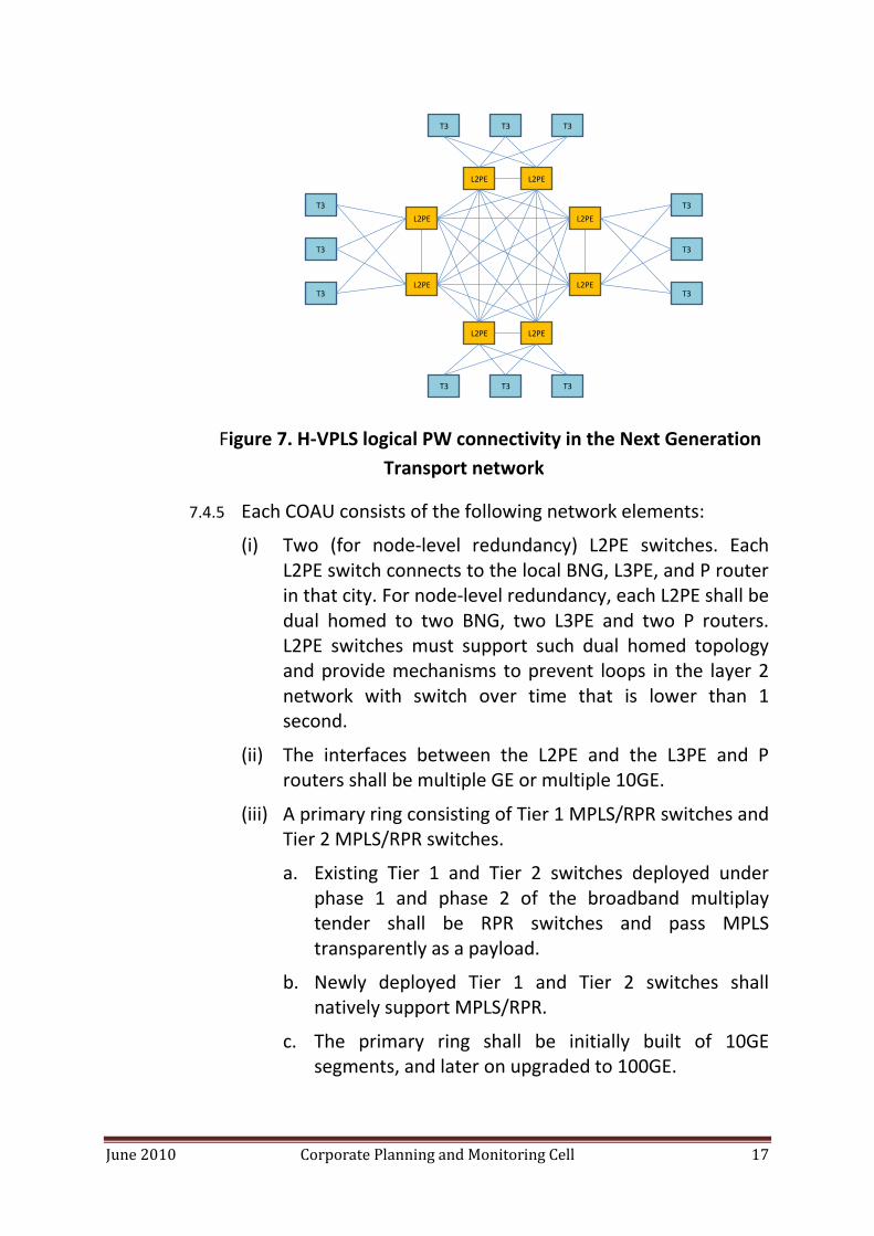
7.4.4 To accommodate the high scalability requirements of NGN (30 million broadband subscribers, 60 millions new 2G subscribers and 9 millions new 3G subscribers in three years), MPLS can be deployed in a hierarchical manner. Hierarchical VPLS (H-VPLS) can be used to reduce the number of LSPs in the network. Rather than having each Tier 3 switch establish an LSP to all its peer Tier 3 switches to which it needs to transport services, the Tier 3 switches can establish LSPs only to their parent L2PE switch (optionally to two parent L2PE switches to achieve node-level redundancy), while each L2PE switches establish an LSP to all its peer L2PE switches to which it needs to transport services. Since full mesh connectivity requires N2 LSPs in the network, reducing N from the number of Tier 3 switches to the number of L2PE switches significantly reduces the overall number of LSPs provisioned in the network, thereby achieving the high scalability requirements of NGN with much lower network resources, which in turn results in much lower CAPEX and OPEX. The H-VPLS concept and its application in the COAU are illustrated in Figure 7. Note that Figure 7 describes the logical LSP connectivity rather than the physical topology. Note also that this is a simplified conceptual view; LSPs can be terminated also in Tier 1 and Tier 2 switches, not necessarily only at Tier 3 switches.
June 2010 Corporate Planning and Monitoring Cell 17
Figure 7. H-VPLS logical PW connectivity in the Next Generation
Transport network
7.4.5 Each COAU consists of the following network elements:
(i) Two (for node-level redundancy) L2PE switches. Each L2PE switch connects to the local BNG, L3PE, and P router in that city. For node-level redundancy, each L2PE shall be dual homed to two BNG, two L3PE and two P routers. L2PE switches must support such dual homed topology and provide mechanisms to prevent loops in the layer 2 network with switch over time that is lower than 1 second.
(ii) The interfaces between the L2PE and the L3PE and P routers shall be multiple GE or multiple 10GE.
(iii) A primary ring consisting of Tier 1 MPLS/RPR switches and Tier 2 MPLS/RPR switches.
a. Existing Tier 1 and Tier 2 switches deployed under phase 1 and phase 2 of the broadband multiplay tender shall be RPR switches and pass MPLS transparently as a payload.
b. Newly deployed Tier 1 and Tier 2 switches shall natively support MPLS/RPR.
c. The primary ring shall be initially built of 10GE segments, and later on upgraded to 100GE.
L2PE
L2PE
L2PE
L2PE
L2PE
L2PE
T3
T3
L2PE
L2PE
T3
T3
T3
T3
T3
T3T3
T3T3T3
June 2010 Corporate Planning and Monitoring Cell 18
d. The Tier 1 switch connects to the L2PE. For node-level redundancy, two Tier 1 switches can be optionally dual homed to two L2PE. MPLS/RPR Tier 1 switches must support such dual homed topology and provide mechanisms to prevent loops in the layer 2 network with switch over time that is lower than 1 second.
e. The Tier 1 switches can potentially, but not necessarily, also perform the function of a L2PE. Specifically, in order to utilize the installed base of Existing Tier 1 and Tier 2 switches deployed under phase 1 and phase 2 of the broadband multiplay project, L2PE switches separate from the Tier 1 switches shall be employed in these cases.
f. One L2PE can be shared across several COAUs if switching capacity requirements permit.
(iv) Subtending secondary rings consisting of Tier 2 MPLS/RPR switches and Tier 3 MPLS/RPR switches.
a. In the case of existing Tier 2 switches deployed under phase 1 and phase 2 of the broadband multiplay tender, such RPR switches will pass MPLS transparently as a payload, and interconnect with either individual Tier 3 switches using multiple GE interfaces, or with a Tier 3 switch terminating a secondary ring, also using multiple GE interfaces.
b. The secondary ring shall be built of 10GE segments.
7.4.6 COAU shall provide following features:
(i) Each COAU will be catering up to 256,000 customers. 10% of the total users are assumed as business users.
(ii) The BNG of Broadband Multiplay is used in each of the aggregation unit for residential services.
(iii) The DSLAMs and GPON OLTs shall be connected to MPLS/RPR Switches (Tier 1, Tier 2 or Tier 3) or to existing RPR switches (Tier 1 or Tier 2), or to existing OCLAN switches backhauled over SDH (this is a temporary solution though the intention is to migrate small cities into Tier 3 MPLS/RPR switches and replace the SDH
June 2010 Corporate Planning and Monitoring Cell 19
transport equipment with Next Generation Transport equipment)
(iv) Traffic from the DSLAMs and GPON OLTs shall be backhauled by the COAU to the nearest BNGs through a Tier 1 RPR switch or through a L2PE which acts as a gateway network element.
(v) The Gateway element shall be connected to BNGs by optical n x GE and 10 GE links as per traffic requirements and BNG interface availability.
(vi) Initially, the LAN Switch will be connected to BNG, which in turn will be connected to MPLS PE router. Over time, due to the high cost of interfaces at the BNG, and its current limited capacity (GE rather than 10GE interfaces), it is desired to gradually offload business services from the BNG, and interconnect the L2PE directly to L3PE (for layer 3 VPN services), to the P routers in the nationwide MPLS core network (for PDH, SDH and Ethernet leased line services, as well as layer 2 VPN services), and to the mobile service edge (for mobile backhauling services). Such offload shall be done whenever and wherever possible (when a Next Generation Transport L2PE switch is deployed in the same city as the BNG, and the required interfaces in the L3PE and P routers are available), and when a business Ethernet service is provided without PPPoE or DHCP which requires termination at the BNG).
7.5 Service models:
Solution shall serve residential and business users, as well as backhauling mobile traffic. Business users are users with direct access to their private VPN. Following service model shall be used:
7.5.1 Residential subscribers with DSL and GPON access lines:
(i) For residential users, ADSL CPE, VDSL CPE and GPON ONT shall be configured to send different type of traffic in different PVCs or different VLANs, and same can be mapped into different service VLANs. DSLAM and OLT
June 2010 Corporate Planning and Monitoring Cell 20
shall put unique inner VLAN tag on each port or shall use DHCP option 82, with common outer VLAN tag per service as per PVC information. This common outer VLAN tag (service based) shall be unique to every DSLAM or every GPON OLT. Inner tag marking or port identification by DHCP option 82 is required for user port identification. DSLAM and GPON OLT shall support both capabilities i.e. insertion of DHCP option 82 as well as inner tag marking per port. It shall be possible to identify any port uniquely with the combination of inner and outer tags or by DHCP option 82.
(ii) COAU shall shape and forward traffic based upon combination of VLAN ID and IEEE 802.1p bit marking.
(iii) COAU shall handoff up to 4K VLANs services per interface toward the BNG.
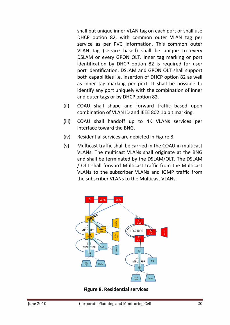
(iv) Residential services are depicted in Figure 8.
(v) Multicast traffic shall be carried in the COAU in multicast VLANs. The multicast VLANs shall originate at the BNG and shall be terminated by the DSLAM/OLT. The DSLAM / OLT shall forward Multicast traffic from the Multicast VLANs to the subscriber VLANs and IGMP traffic from the subscriber VLANs to the Multicast VLANs.
Figure 8. Residential services
P L3PE
T1 RPR
T2 RPR
T2 RPR
L2PE
T2MPLS/
RPR
GP
ON
O
LT
DSL
AM10G RPR
10G MPLS/RPR
DSL
AM
DSLAMSDH/PDH
T3
T3
10G MPLS/RPR
T3
DSLAMSDH/PDH
T3
T3
10G MPLS/RPR
T2MPLS/
RPR
DSL
AM
BNG
June 2010 Corporate Planning and Monitoring Cell 21
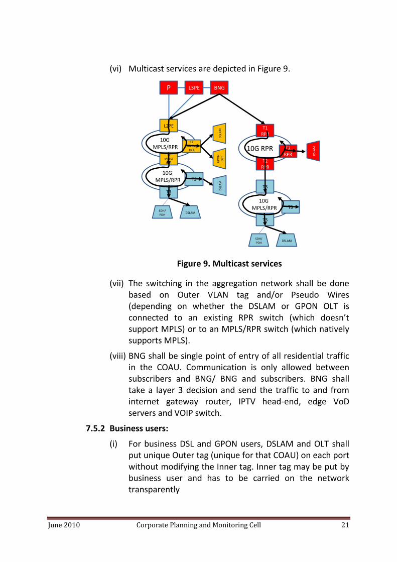
(vi) Multicast services are depicted in Figure 9.
Figure 9. Multicast services
(vii) The switching in the aggregation network shall be done based on Outer VLAN tag and/or Pseudo Wires (depending on whether the DSLAM or GPON OLT is connected to an existing RPR switch (which doesn’t support MPLS) or to an MPLS/RPR switch (which natively supports MPLS).
(viii) BNG shall be single point of entry of all residential traffic in the COAU. Communication is only allowed between subscribers and BNG/ BNG and subscribers. BNG shall take a layer 3 decision and send the traffic to and from internet gateway router, IPTV head-end, edge VoD servers and VOIP switch.
7.5.2 Business users:
(i) For business DSL and GPON users, DSLAM and OLT shall put unique Outer tag (unique for that COAU) on each port without modifying the Inner tag. Inner tag may be put by business user and has to be carried on the network transparently
P L3PE BNG
T1 RPR
T2 RPR
T2 RPR
L2PE
T2MPLS/
RPR
GP
ON
O
LT
DSL
AM10G RPR
10G MPLS/RPR
DSL
AM
DSLAMSDH/PDH
T3
T3
10G MPLS/RPR
T3
DSLAMSDH/PDH
T3
T3
10G MPLS/RPR
T2MPLS/
RPR
DSL
AM

June 2010 Corporate Planning and Monitoring Cell 22
(ii) Initially, COAU shall transparently pass the outer & inner tag information to the broadband network gateway (BNG).
(iii) Over time, BNG shall be offloaded by direct connections between the L2PE and the L3PE and the P routers.
(iv) In order to perform such offload, communication between subscribers shall be done by the MPLS/RPR switches or by the L2PE:
(v) For point to point Ethernet services, MPLS/RPR switch shall encapsulate the Ethernet traffic over a Pseudo Wire and send it to one of the following:
a. To its destination MPLS/RPR switch, in case the service is terminated in a DSLAM or GPON OLT connected to a MPLS/RPR switch.
b. To a gateway L2PE, in case the service is terminated in a DSLAM connected to a RPR switch which doesn’t have native MPLS functionality. The gateway L2PE will terminate the PW and forward the traffic to the BNG over VLAN. In case the non MPLS Tier 1 switch is collocated with the L2PE then the gateway L2PE will terminate the PW and forward the traffic directly to the Tier 1 switch over VLAN.
(vi) Point to point Ethernet services are depicted in Figure 10.
Figure 10. Point to point Ethernet services
P L3PE BNG
T1 RPR
T2 RPR
T2 RPR
L2PE
T2MPLS/
RPR
GP
ON
O
LT
DSL
AM10G RPR
10G MPLS/RPR
DSL
AM
DSLAMSDH/PDH
T3
T3
10G MPLS/RPR
T3
DSLAMSDH/PDH
T3
T3
10G MPLS/RPR
T2MPLS/
RPR
DSL
AM
P
L2PE
T2MPLS/
RPR
T2MPLS/
RPR
10G MPLS/RPR
L3PEBNG
DSLAMSDH/PDH
T3
T3
10G MPLS/RPR
DSL
AM
June 2010 Corporate Planning and Monitoring Cell 23
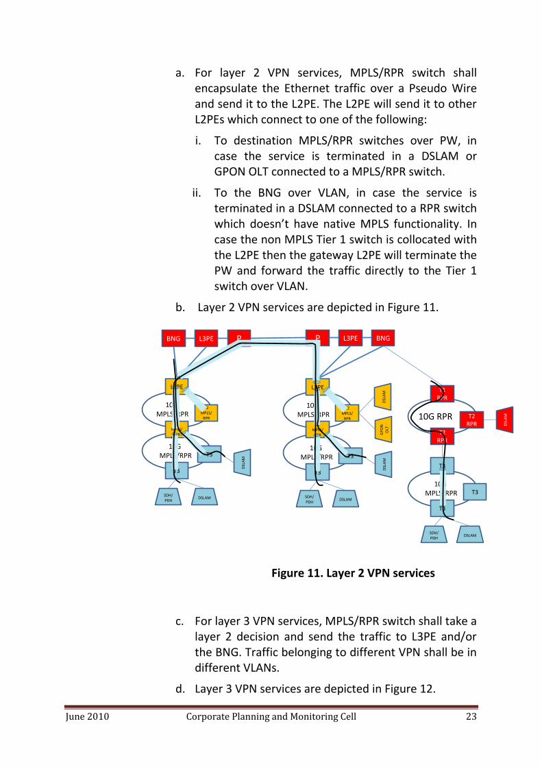
a. For layer 2 VPN services, MPLS/RPR switch shall encapsulate the Ethernet traffic over a Pseudo Wire and send it to the L2PE. The L2PE will send it to other L2PEs which connect to one of the following:
i. To destination MPLS/RPR switches over PW, in case the service is terminated in a DSLAM or GPON OLT connected to a MPLS/RPR switch.
ii. To the BNG over VLAN, in case the service is terminated in a DSLAM connected to a RPR switch which doesn’t have native MPLS functionality. In case the non MPLS Tier 1 switch is collocated with the L2PE then the gateway L2PE will terminate the PW and forward the traffic directly to the Tier 1 switch over VLAN.
b. Layer 2 VPN services are depicted in Figure 11.
Figure 11. Layer 2 VPN services
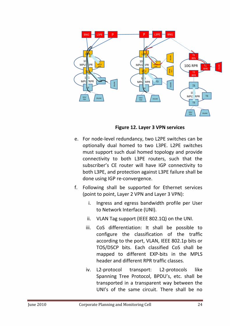
c. For layer 3 VPN services, MPLS/RPR switch shall take a layer 2 decision and send the traffic to L3PE and/or the BNG. Traffic belonging to different VPN shall be in different VLANs.
d. Layer 3 VPN services are depicted in Figure 12.
P L3PE BNG
T1 RPR
T2 RPR
T2 RPR
L2PE
T2MPLS/
RPR
GP
ON
O
LT
DSL
AM10G RPR
10G MPLS/RPR
DSL
AM
DSLAMSDH/PDH
T3
T3
10G MPLS/RPR
T3
DSLAMSDH/PDH
T3
T3
10G MPLS/RPR
T2MPLS/
RPR
DSL
AM
P
L2PE
T2MPLS/
RPR
T2MPLS/
RPR
10G MPLS/RPR
L3PEBNG
DSLAMSDH/PDH
T3
T3
10G MPLS/RPR
DSL
AM
June 2010 Corporate Planning and Monitoring Cell 24
Figure 12. Layer 3 VPN services
e. For node-level redundancy, two L2PE switches can be optionally dual homed to two L3PE. L2PE switches must support such dual homed topology and provide connectivity to both L3PE routers, such that the subscriber’s CE router will have IGP connectivity to both L3PE, and protection against L3PE failure shall be done using IGP re-convergence.
f. Following shall be supported for Ethernet services (point to point, Layer 2 VPN and Layer 3 VPN):
i. Ingress and egress bandwidth profile per User to Network Interface (UNI).
ii. VLAN Tag support (IEEE 802.1Q) on the UNI.
iii. CoS differentiation: It shall be possible to configure the classification of the traffic according to the port, VLAN, IEEE 802.1p bits or TOS/DSCP bits. Each classified CoS shall be mapped to different EXP-bits in the MPLS header and different RPR traffic classes.
iv. L2-protocol transport: L2-protocols like Spanning Tree Protocol, BPDU’s, etc. shall be transported in a transparent way between the UNI’s of the same circuit. There shall be no
P L3PE BNG
T1 RPR
T2 RPR
T2 RPR
L2PE
T2MPLS/
RPR
GP
ON
O
LT
DSL
AM10G RPR
10G MPLS/RPR
DSL
AM
DSLAMSDH/PDH
T3
T3
10G MPLS/RPR
T3
DSLAMSDH/PDH
T3
T3
10G MPLS/RPR
T2MPLS/
RPR
DSL
AM
P
L2PE
T2MPLS/
RPR
T2MPLS/
RPR
10G MPLS/RPR
L3PEBNG
DSLAMSDH/PDH
T3
T3
10G MPLS/RPR
DSL
AM
June 2010 Corporate Planning and Monitoring Cell 25
interference with L2-protocols of the BSNL’s network.
v. Service multiplexing: a single port can support multiple Ethernet Services.
vi. Limitation of MAC addresses learned per service. The number of MAC addresses learned per service shall be configurable. Frames with new source MAC-addresses exceeding the configured value shall be dropped.
vii. Q-in-Q support: MPLS/RPR switches shall perform classification and service delineation based on outer Q tag and outer IEEEE 802.1p bits only (i.e. ignore inner tag).
viii. End-to-end protection for each LSP, providing an additional layer of protection above RPR and LAG. Such protection scheme is not required to be sub-50ms.
ix. Ethernet OAM CCM as per IEEE 802.1ag. The provisioning of all expected MEP IDs shall be automated via the EMS.
7.5.3 PDH and SDH leased line services:
(i) PDH services can be terminated in either E1 interfaces or channelized STM-1 or STM-4 interfaces in Tier 3 switches.
(ii) PDH services are terminated in channelized STM-1 or STM-4 interfaces in Tier 1 and Tier 2 switches (due to the high switching capacity of the Tier 1 and Tier 2 switches, it is not economical to waste expensive switching capacity on physical E1 interfaces in these switches).
(iii) SDH services can be terminated in STM-1, STM-4 and STM-16 interfaces in Tier 1, Tier 2 or Tier 3 switches.

June 2010 Corporate Planning and Monitoring Cell 26
(iv) E1 payload is encapsulated by the terminating MPLS/RPR switch over PW using SATOP as per RFC 4553.
(v) SDH payload (VC12, VC3 or VC4) is encapsulated by the terminating MPLS/RPR switch over PW using CEP as per RFC 4842.
(vi) The MPLS/RPR switch must be able to perform low order (VC12 granularity) and high order (VC3/VC4 granularity) cross connect and grooming between each SDH interface port and each PW attached to an SDH line card.
(vii) The MPLS/RPR switch must support MSP 1+1 protection for paired SDH interfaces on adjacent line cards.
(viii) It shall be possible to protect PDH and SDH leased line services using End-to-end protection for each LSP, in order to provide an additional layer of protection above RPR and LAG. Such protection scheme is not required to be sub-50ms.
(ii) PDH and SDH services are depicted in Figure 13.
Figure 13. PDH and SDH services
P L3PE BNG
T1 RPR
T2 RPR
T2 RPR
L2PE
T2MPLS/
RPR DSL
AM10G RPR
10G MPLS/RPR
DSL
AM
DSLAMSDH/PDH
T3
T3
10G MPLS/RPR T3
DSLAMSDH/PDH
T3
T3
10G MPLS/RPR
T2MPLS/
RPR
DSL
AM
P
L2PE
T2MPLS/
RPR
T2MPLS/
RPR
10G MPLS/RPR
L3PEBNG
DSLAMSDH/PDH
T3
T3
10G MPLS/RPR
SDH
/P
DH
SDH
June 2010 Corporate Planning and Monitoring Cell 27
7.5.4 Mobile backhauling services:
(i) 2G mobile backhauling services are provided in the same manner as PDH and SDH leased line services.
(ii) 3G, WiMax and 4G backhauling services are provided in the same manner as Ethernet point-to-point and Layer 2 VPN services.


