Network CommunicationsChapter 7
Modems, DSL, Cable Modems and ISDN
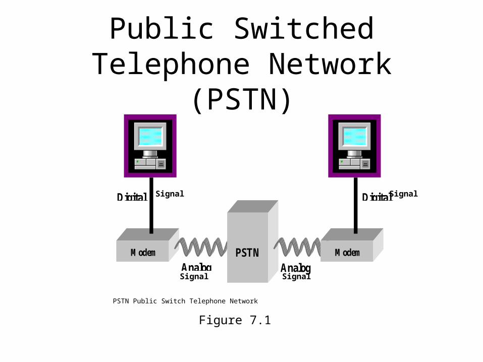
Public Switched Telephone Network (PSTN)
Figure 7.1
AnalogAnalog
DigitalDigital
Modem PSTN Modem
Signal Signal
Signal Signal
PSTN Public Switch Telephone Network
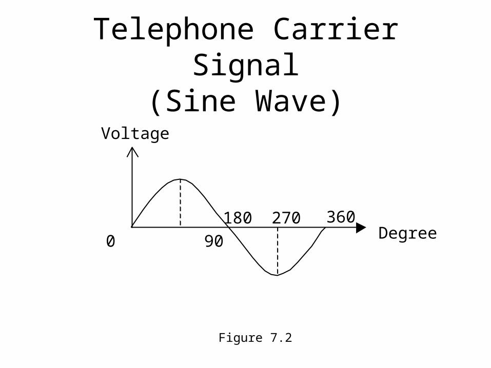
Telephone Carrier Signal(Sine Wave)
Voltage
180 270
0 90
360Degree
Figure 7.2
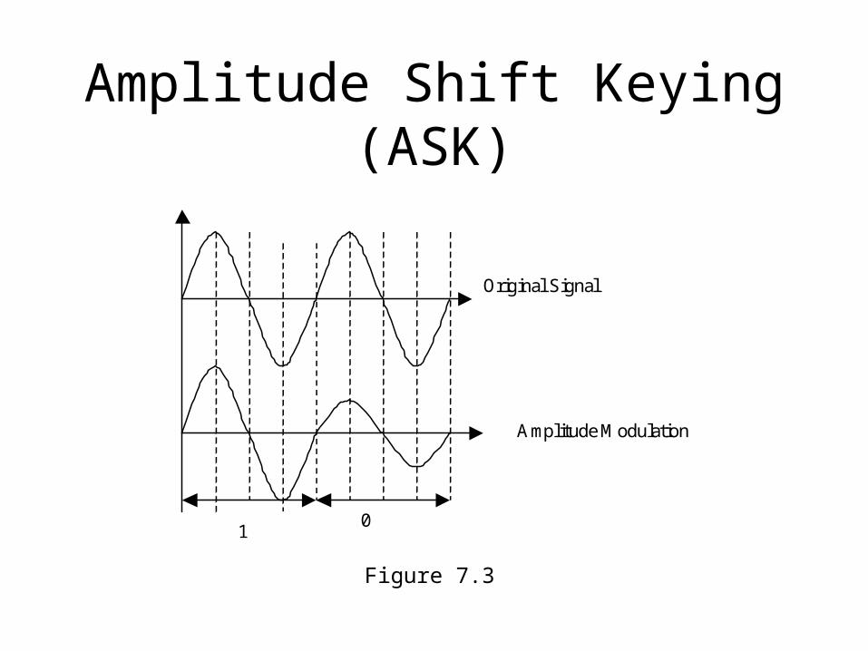
Amplitude Shift Keying (ASK)
Figure 7.3
01
Original Signal
Amplitude Modulation
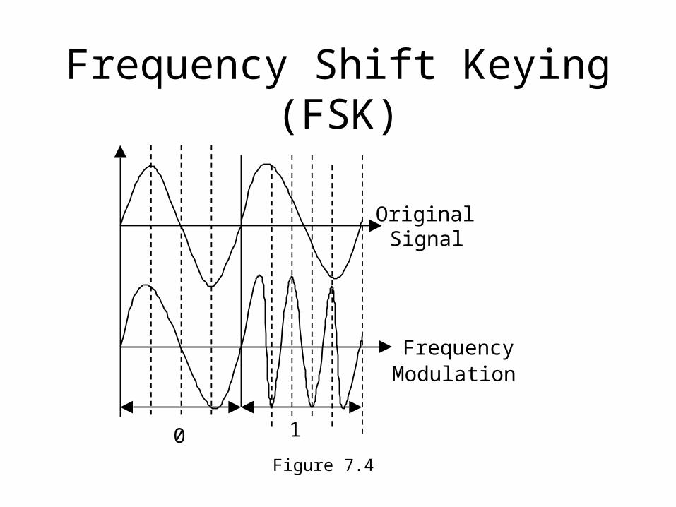
Frequency Shift Keying (FSK)
Figure 7.4
10
OriginalSignal
FrequencyModulation
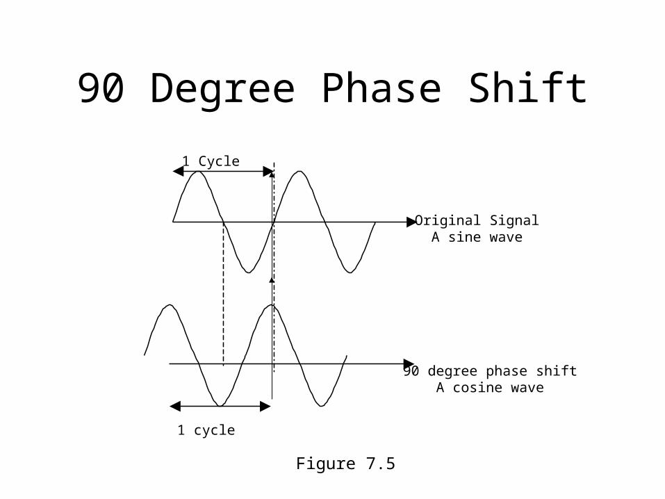
90 Degree Phase Shift
Figure 7.5
1 Cycle
Original SignalA sine wave
90 degree phase shiftA cosine wave
1 cycle
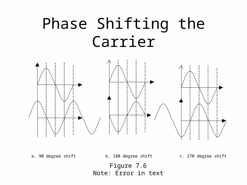
Phase Shifting the Carrier
Figure 7.6Note: Error in text
a. 90 degree shift b. 180 degree shift c. 270 degree shift
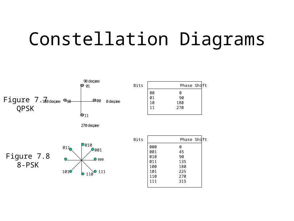
Constellation Diagrams
Figure 7.7QPSK
0 degree
90 degree
180 degree
270 degree
00
01
10
11
Figure 7.88-PSK
000
010
110
001011
101 111
000 0001 45010 90011 135100 180101 225110 270111 315
Bits Phase Shift
00 00110
90
11180270
Bits Phase Shift
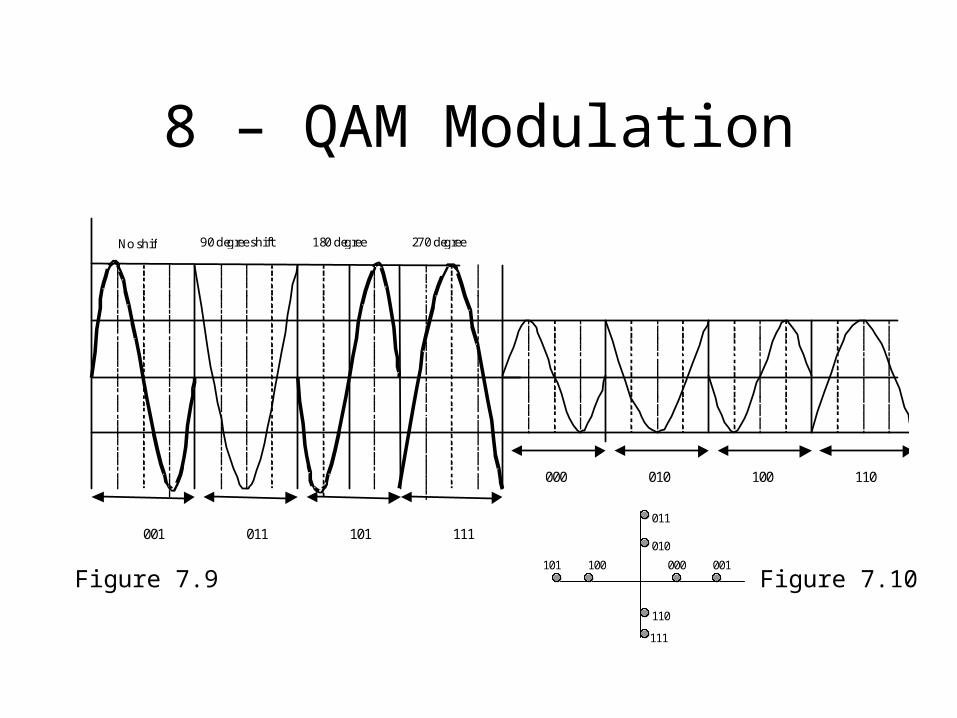
8 – QAM Modulation
Figure 7.9
No shift 90 degree shift 180 degreeshift
270 degreeshift
000 010 100 110
001 011 101 111
Figure 7.10000 001
011
010
101 100
110
111
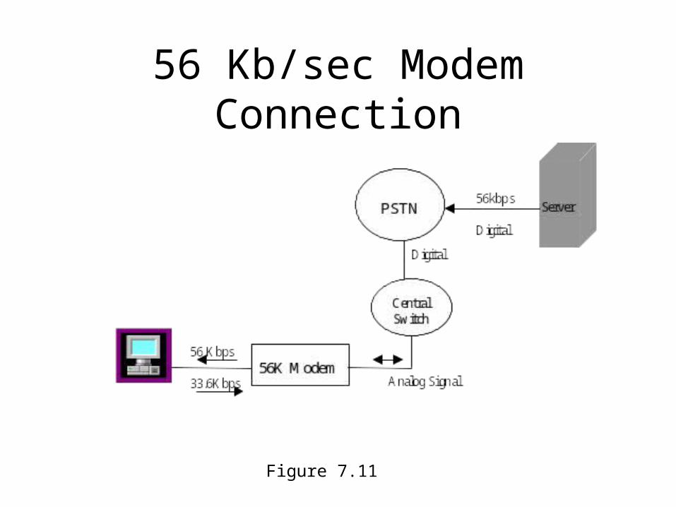
56 Kb/sec Modem Connection
Figure 7.11
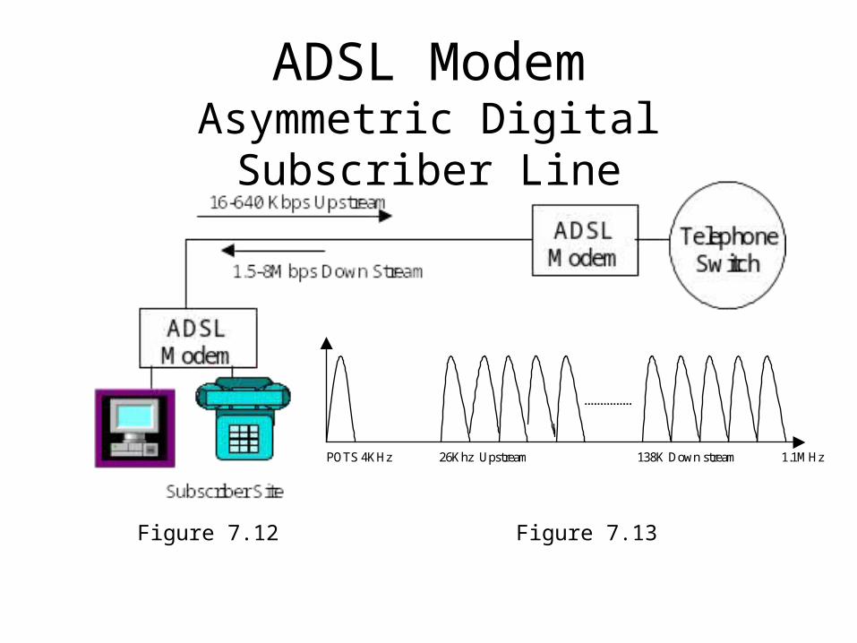
ADSL ModemAsymmetric Digital Subscriber Line
Figure 7.12 Figure 7.13
POTS 4KHz 26Khz Upstream 138K Down stream 1.1MHz
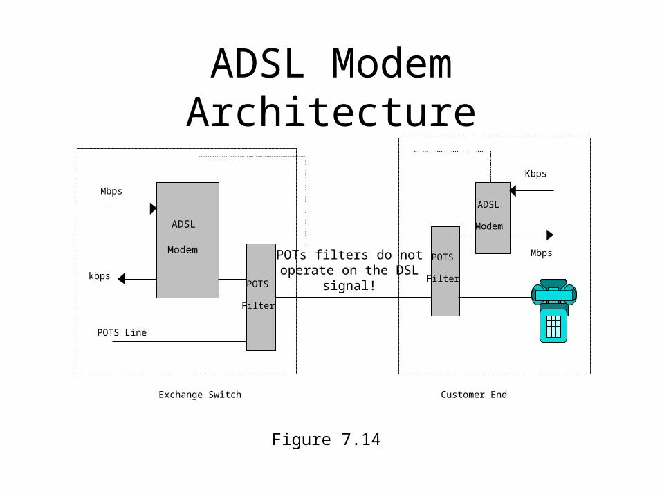
ADSL Modem Architecture
Figure 7.14
ADSL
Modem
POTS
Mbps
kbps
Filter
POTS Line
Exchange Switch
POTS
Filter
ADSL
Modem
Mbps
Kbps
Customer End
POTs filters do notoperate on the DSL
signal!
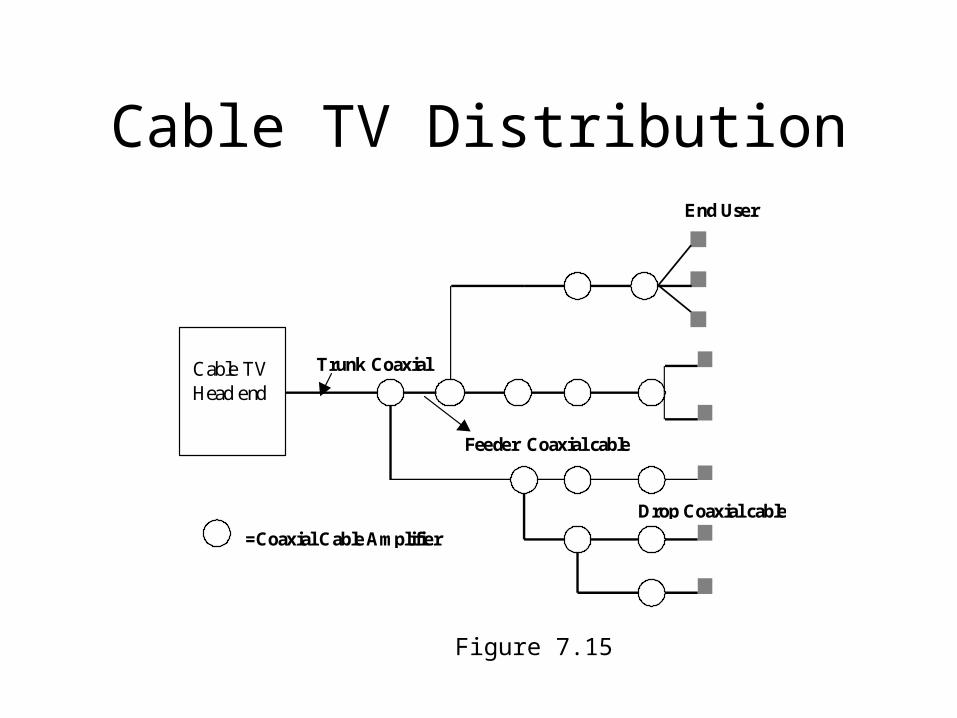
Cable TV Distribution
=Coaxial Cable Amplifier
End User
Trunk Coaxial
Feeder Coaxial cable
Drop Coaxial cable
Cable TVHead end
Figure 7.15
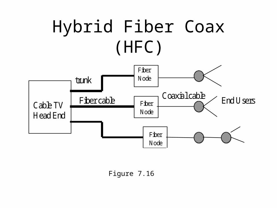
Hybrid Fiber Coax (HFC)
Figure 7.16
Cable TVHead End
FiberNode
FiberNode
FiberNode
trunk
Fiber cable Coaxial cable End Users
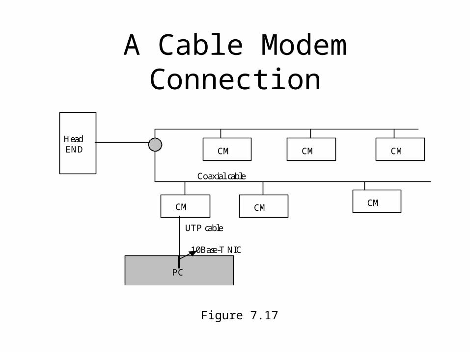
A Cable Modem Connection
Figure 7.17
HeadEND CM CMCM
CM CM CM
PC
10Base-T NIC
UTP cable
Coaxial cable
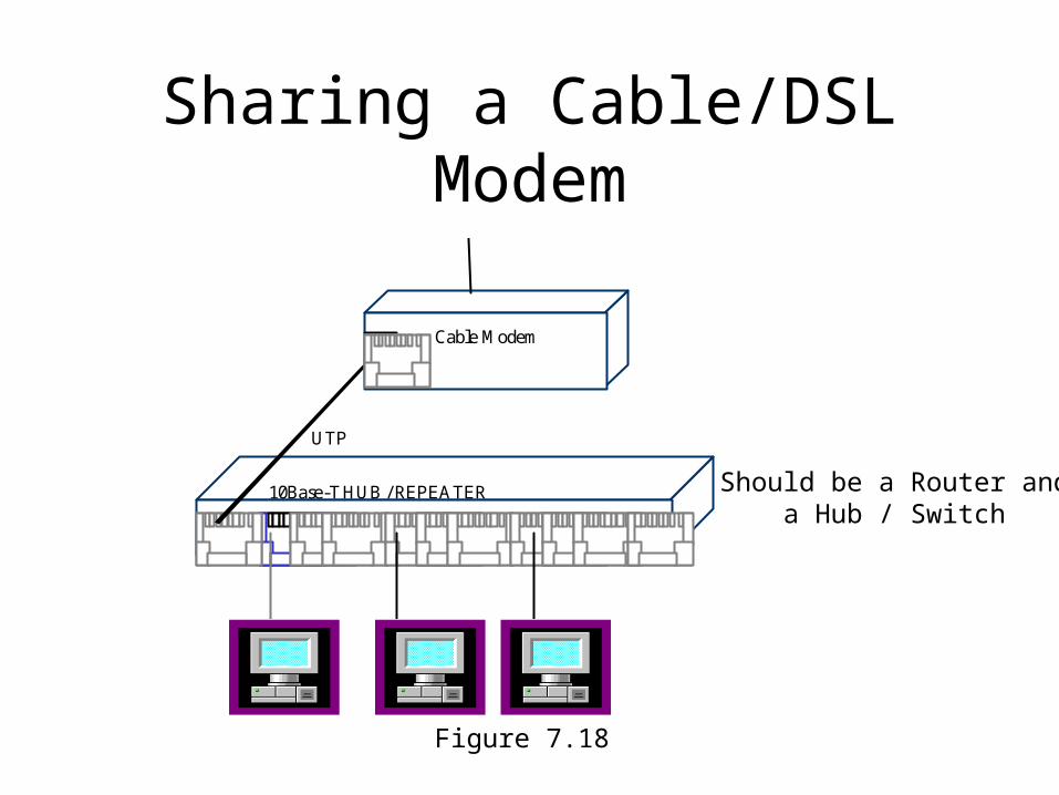
Sharing a Cable/DSL Modem
Figure 7.18
HUB / REPEATER
Cable Modem
UTP
10Base-T Should be a Router anda Hub / Switch
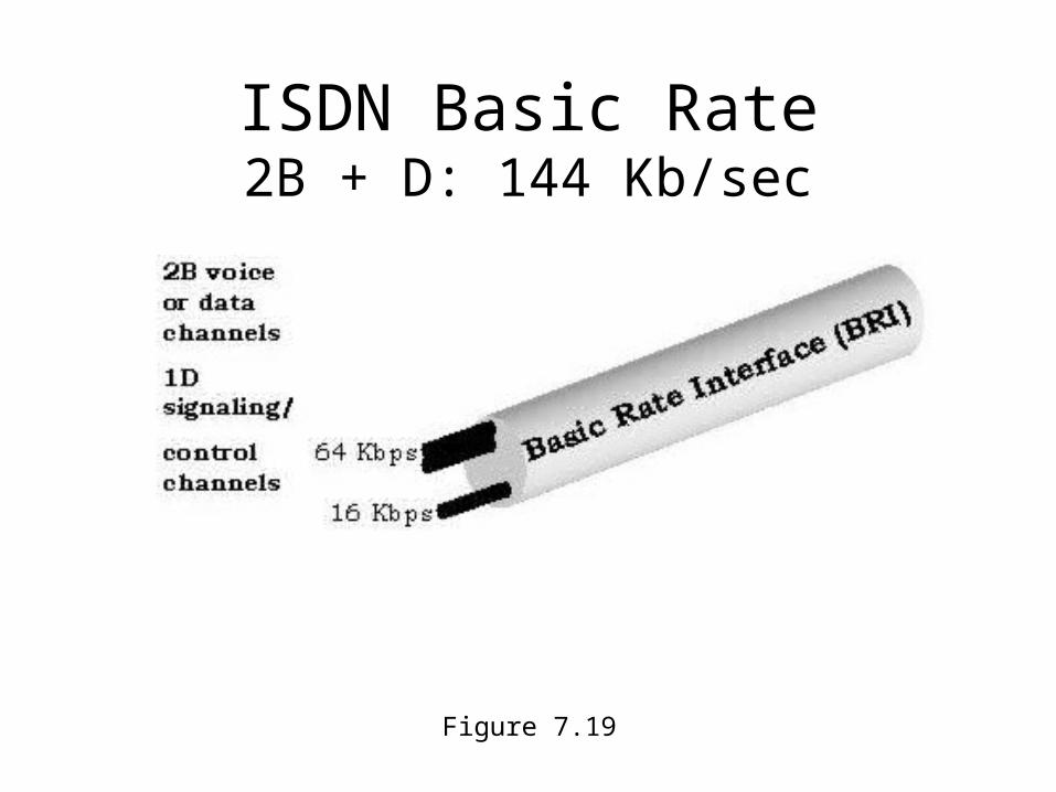
ISDN Basic Rate2B + D: 144 Kb/sec
Figure 7.19
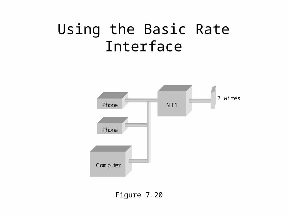
Using the Basic Rate Interface
Computer
Phone
Phone NT12 wires
Figure 7.20
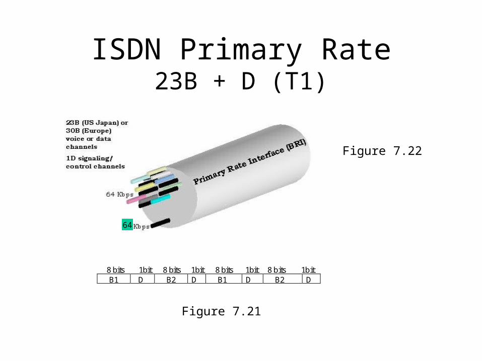
ISDN Primary Rate23B + D (T1)
Figure 7.21
8 bits 1bit 8 bits 1bit 8 bits 1bit 8 bits 1bit B1 D B2 D B1 D B2 D
64
Figure 7.22
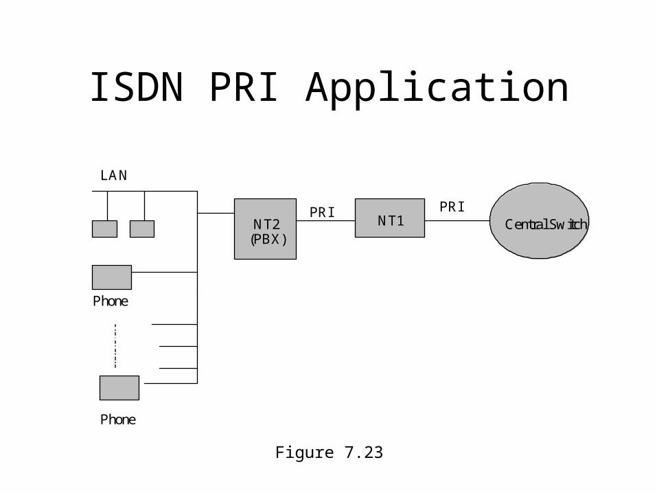
ISDN PRI Application
Figure 7.23
Central SwitchNT1PRI
NT2(PBX)
LAN
Phone
Phone
PRI


