
MODELING AUTONOMOUS MOBILE ROBOT SYSTEM WITH AN OBJECT ORIENTED APPROACH Jun Okamoto Junior Departamento de Engenharia Mecatrônica e de Sistemas Mecânicos Escola Politécnica da Universidade de São Paulo Av. Prof. Mello Moraes, 2231 05508-900 São Paulo, SP, Brazil [email protected] Valdir Grassi Junior Departamento de Engenharia Mecatrônica e de Sistemas Mecânicos Escola Politécnica da Universidade de São Paulo Av. Prof. Mello Moraes, 2231 05508-900 São Paulo, SP, Brazil [email protected] Fabiano Rogério Correa Departamento de Engenharia Mecatrônica e de Sistemas Mecânicos Escola Politécnica da Universidade de São Paulo Av. Prof. Mello Moraes, 2231 05508-900 São Paulo, SP, Brazil [email protected] Abstract. Object oriented approach has proved its benefits in software development and systems organization. Researchers are envisioning new areas that can benefit also from the application of this approach. In the robot control field there are some projects around the world that are bringing together robot control structures modeled by object oriented approach. This paper will present the modeling process of an autonomous mobile robot with an object oriented approach. The robot task is modeled by a Business Process Modeler that links to the robot control structure modeled by UML. The realization of the control algorithms is extracted directly form the object oriented model. The implementation of this model can be achieved by distributed objects implemented using CORBA or other equivalent mechanism. This approach will take the development of mobile robot control systems to benefit from a general distributed control system. Keywords: Object-Oriented Programming, UML, Mobile Robot Navigation.
1. Introduction
Object oriented approach has proved its benefits in software development and systems organization. Researchers are envisioning new areas that can benefit also from the application of this approach. In the robot control field there are some projects around the world that are bringing together robot control structures modeled by object oriented approach. The aim of these projects is mainly build a modular control structure composed of specialized components for each different function in the robot system. Each component has a well-defined role and interface. One software component is not coupled with another one. For this reason, as independent part of the system, each software component act as a building block to construct the robot control structure to solve the task of interest. This modularity approach makes a software component reusable and it lets that one component be replaced with a different one with the same interface and function in the system. For example, consider two different robots. Despite each robot may have physical differences that reflect in a particular way to control its movement, both could receive commands to move to a particular direction with a heading velocity. For this reason they could be represented as software components with the same interface, and one robot could be easily replaced by another one without deeper changes in the control software. The different ways each robot control its movements are encapsulated inside the component.
The Open Robot Control Software (OROCOS) project described by Bruyninckx (2001) aims to develop a general-purpose and open robot control software package based on components. This project benefits from two of the major evolutions in software engineering: object-orientation and software patterns. The modularity and flexibility in the software package being developed in OROCOS project would allow building complex robot systems integrating components for kinematics, dynamics, planning, control, hardware interface, etc. Each of these components would be a software object that would be added or removed from a network and would offer its services through a neutral, programming language interface such as CORBA’s Interface Description Language IDL. This would allow interoperability between components even if the components were written using different programming language or were run on machines with different operational systems. The package resulting of the OROCOS project will help to meet a need in robotic research for reusable functional components to build and test robot control systems.
Other researchers also made use of object-oriented concepts applied to robotics. Hori et al (1999) proposed an approach to networked robot system. They consider networked robots as distributed objects and introduce a distributed object computing approach to them. The authors use CORBA as middleware to allow communication and interoperability between the different robots. Murphy (2000) also mentions examples in her book of how a reactive
architecture could be benefited of object-oriented programming. The behaviors in the architecture could be represented as objects, and each object would be composed using one perceptual class and one action class. The works mentioned previously are only some examples of the recent works done in this field.
This paper will present the modeling process of an autonomous mobile robot task with an object-oriented approach. The modeling process starts with a Business Process Model passing to UML diagrams that describe the designed solution to implement the task control system. Then some aspects of the implementation are discussed showing that the implementation of the system can be achieved using distributed objects.
2. Business Process Model of a Robotic Navigation Task
We choose a robotic navigation task to be object-oriented modeled. In this task, the robot has a goal, which is a place where it has to go. The problem consists in self-localization through all the way in relation to the goal. The information that is provided to the system is the direction and the distance of the goal to the robot. Thus the robot must cope with errors in the movements through the readings of its sensors.
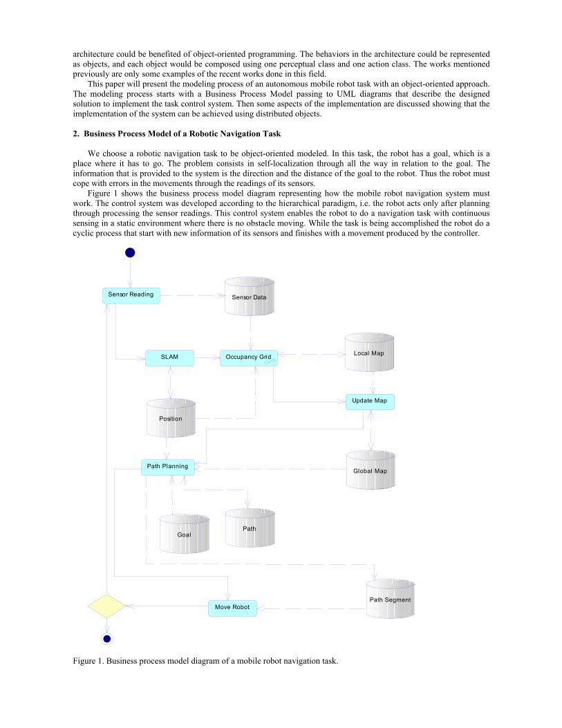
Figure 1 shows the business process model diagram representing how the mobile robot navigation system must work. The control system was developed according to the hierarchical paradigm, i.e. the robot acts only after planning through processing the sensor readings. This control system enables the robot to do a navigation task with continuous sensing in a static environment where there is no obstacle moving. While the task is being accomplished the robot do a cyclic process that start with new information of its sensors and finishes with a movement produced by the controller.
Sensor Reading Sensor Data
Local Map
Global Map
Path
Occupancy Grid
Move Robot
Position
SLAM
Path Planning
Update Map
Goal
Path Segment
Figure 1. Business process model diagram of a mobile robot navigation task.
When the navigation task starts, the first process (processes are indicated in the diagram as boxes) executed is the
Sensor Readings that updates the resource Sensor Data (resources are represented by cylinders) according the information retrieved by range sensors in the robot. Sensor Data is a list of spatial coordinates. These coordinates are the ending points of the vectors starting in the robot and ending in the detected obstacles.
After Sensor Readings another process named SLAM is executed. SLAM (Simultaneous Localization And Mapping) is a statistical framework for simultaneously solving the mapping problem and the induced problem of localizing the robot relative to a growing map. As the robot is navigating toward its goal, it needs to use information of its sensor for self-localization. This allows the robot to correct its path and to use an estimative of its position to incorporate a local map in the global one. Basically the SLAM algorithm is an estimator that can integrate information of several sensor sources (such as dead reckoning) to obtain a better estimative of the robot position in space (Smith et al., 1990). In the diagram, the SLAM process accesses the resource Position and updates it based on the new Sensor Data.
With Position and Sensor Data updated, the Occupancy Grid process is called. The Occupancy Grid transforms that list of coordinates (Sensor Data) in a tessellated map of probability of obstacles occupying a specific cell (Elfes, 1989). It accesses the resource Local Map and updated it. This map can be represented as a matrix where the value of each element, or cell, represents the probability of occupation in an area of the space. After the Occupancy Grid provides an updated Local Map, the process Update incorporates the Local Map in the Global Map.
Then the process Path-planning is called and provided with the updated Global Map, with the resource Goal of the navigation task and with the actual location of the robot (Position). The Path-planning produces a resource named Path that is the whole path to be followed by the robot in order to achieve the goal position. The Path can be represented as a sequence of coordinates interpolated by straight lines. Each line is a path segment of the whole path.
The planning is made in a coarse-to-fine way. Firstly, the space around the robot is divided in great areas through radial rays and concentric circles starting from the robot. The areas in every circle that seems to be poorly occupied are chosen and marked. Those marks are united through lines forming a coarse path. Secondly, each line is closer investigated using the map to determine a better trajectory resulting on the fine-tuned path that will be followed by the robot.
Besides the whole Path, the Path-planning also provides and updates the resource Path Segment. This resource gives the current line segment to be followed by the robot. Finally, the process Move Robot uses the Path Segment resource to send commands to act the robot. While the robot does not reach the resource Goal provided externally by a user, a new cycle begins.
The business process model allows the developer to describe a general solution for the problem. In this step, the main processes and information used in the solution are specified. The business model helps the developer organize his solution idea before he can start to deal with a modeling level more close to the implementation.
3. UML diagrams
Using the Unified Modeling Language (UML) it is possible to specify the object-oriented software solution in a
level more close to the implementation. The UML specification includes nine diagrams each of them representing a viewpoint of the system: class diagram, object diagram, use case diagram, sequence diagram, collaboration diagram, statechart diagram, activity diagram, component diagram, deployment diagram.
In this paper we will present two of these diagrams: the class diagram and the sequence diagram. The first one is a static representation of the system showing the classes and their relationship. The sequence diagram is a dynamic representation that shows interaction between objects created from the classes emphasizing the time ordering of messages.
3.1. Class diagram
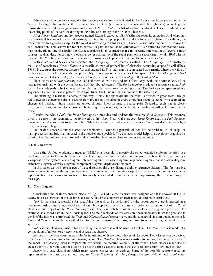
Considering the business process model of Fig. 1, a UML class diagram was designed and it is showed in Fig. 2.
Below it is a description of the designed classes with a brief comment on their methods and main attributes. Task is the class responsible for specifying the task to be performed by the robot. As we are interested in a
navigation task using a single robot and a hierarchic approach, the Task class will make use of one object of the Robot class and one object of the Path Planning class. The main attribute of the Task class is the goal represented, for example, as a coordinate in the 2D task space. The main methods of this class are those necessary to set the goal and to verify if the task was completed, SetGoal and IsGoalAchieved respectively, and those methods to start and stop the task, Start and Stop respectively. A method to return some measure of the progress done to achieve the goal could also be specified.
Robot is the class responsible for describing the robot that will be used in the task. The Robot class is made of a composition of at least one Actuator and at least one Sensor.
Actuator is the base class responsible for interfacing with the motor drives of the robot. Two classes can be derived of Actuator class: Heading class and Steering class. The Heading class is responsible for setting the cruiser velocity of the robot. The Steering class is responsible for setting the steering velocity of the robot. These classes make use of closed control algorithms, and it is also possible to define classes to handle these closed loop controllers such as PID.
Sensor is a base class from which many sensor classes can be derived. Some of the possible sensor classes are represented in the class diagram and they are Force, Proximity, Tracker, Range, Position, Velocity and Accelerator.
Many other sensors can be defined according to the need of the application designer. The common attributes of these sensors are the update_time that gives the interval of time when a new reading is available, and probabilistic parameters such as the variance of the sensor error. The common methods are Start, Stop, SetUpdateTime, GetUpdateTime, SetVariance, GetVariance, and Read. The Read method returns the information for which the specific sensor is responsible.
Position, Velocity and Accelerator classes are responsible for giving internal information about the actual state of the robot. The Position class can be based on the readings of encoders to estimate the robot position. This is known as dead reckoning and it is well known that such method of estimate robot position propagates errors in such manner that after some time the uncertainty of robot position is considerable great to be used on a navigation task. For this reason, the Position class has, besides the inherited methods and attributes of the Sensor class, a method called SetPosition with which is possible to correct the position of the robot. The correction can be done by localization methods of the Map class, such as SLAM method. The Velocity and Accelerator class has only same methods and attributes of the Sensor class
1..1
1..*
1..1
1..*
0..* 0..*
1..1
1..*
0..1
0..1 0..1
1..10..1
0..*
0..1
0..*
0..1
0..*
0..1
0..*
0..1
0..*
1..*
1..1
0..1
0..11..1
1..1
0..10..* 0..1
0..1
Robot
SensorActuator
Map
Local Map
Global Map
Planning
Task
RangeProximity Position Velocity AcceleratorForce
Stereo Vision
EncoderSonar Infra Red
Image
Video
Tracker
Target
Heading
Steering
Pan Tilt
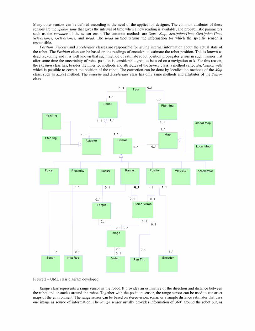
Figure 2 – UML class diagram developed
Range class represents a range sensor in the robot. It provides an estimative of the direction and distance between the robot and obstacles around the robot. Together with the position sensor, the range sensor can be used to construct maps of the environment. The range sensor can be based on stereovision, sonar, or a simple distance estimator that uses one image as source of information. The Range sensor usually provides information of 360° around the robot but, as
this is not necessarily true for all kind of robots and sensors, the Range class has methods and attributes to define and retrieve where are the blind regions of the range sensor. As the sensor can not obtain information about those blind regions, this must be treated when building maps.
Proximity is the class that represents the proximity sensor of the robot. A proximity sensor can detect when an object is close to the robot. This sensor does not return the distance between the robot and the object detected but instead just returns which direction the object was detected. Similarly with the range sensor, the proximity sensor also may have blind regions.
Tracker is the class responsible to describe a visual tracking sensor. Through this sensor is possible to track an object in an image and to retrieve some information about the visual changes suffered by this object. This kind of sensor is used on visual servo control tasks such as the task described by Okamoto Jr and Grassi Jr (2002) were a robot using a vision system follows an object keeping a constant distance between the robot and the object.
Stereo Vision is one of the classes that can be used by the Range sensor class. Stereo Vision is responsible to acquire and process one pair of images and to provide distance estimation from obstacles. The two images required must be taken from two different viewpoints. For this reason, if the robot has one single camera that provides an image from a single viewpoint, the robot or the camera must be moved before acquiring another image. So the Stereo Vision class uses the Position class to determine if the robot has moved and the distance moved by the robot between two camera shots. The Stereo Vision may use the Pan-tilt class to move only the camera if the camera is mounted on a pan-tilt mechanism.
Image is a class to support methods for image processing and image manipulation. Some of the methods that can be implemented in this class are Gradient, Threshold, Labeling, ImageCopy, GetWidth, GetHeight, etc.
The classes on the bottom of the class diagram provide the interface with the hardware of the system. The Video is a class to support the interface with the frame grabber hardware. Through the methods of this class is possible to grab an image after setting the dimension and color of this image. Sonar is a class to support the interface with the sonar hardware. It is used to provide distance estimation from robot to obstacles. Infra Red supports interface with the infrared hardware used to detect proximity. Encoder supports interface with an encoder sensor mounted on each motor shaft of the robot. The encoders are used on dead reckoning methods to estimate the robot location.
Planning is the class responsible for the path planning algorithms used in the navigation task. The Planning class uses the Map class to take decisions about the path the robot should follow. The main attribute of the Planning class is the Goal position set by the Task. As described in the business process model section, this class generates the whole path and the actual path segment the robot should follow. For this reason, this class must have methods to retrieve such information and methods to get the next path segment given the current robot position. So some of the methods of this class are SetGoal,FindGlobalPath,and GetPathSegment.
Map is the class responsible for storing and manipulating the maps. There are two classes derived from it that represent the two different types of map: Local Map and Global Map. Both local and global maps can represent the map using occupancy grids (Elfes, 1989), and the current robot position is indicated on the maps. The Local Map has a method called Slam that uses SLAM algorithm that allows correcting the robot position. The Global Map class has a method called Update that allows the local map to be fused on the global map.
3.2. Sequence Diagrams
The behavior of the objects can be better understood using sequence diagrams. The sequence diagram shows in
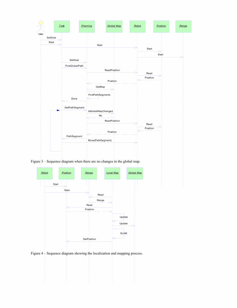
time order the methods called by the objects in some specific situation. Consider, for example, the case when a global map was given to the user and he points the goal position in the map. Suppose that there are no unforeseen obstacles and the environment is static so that the global map is very close to the real one. This implies that the global map does not change during the task and for this reason a re-planning is not necessary. The sequence diagram for this situation is shown in the Fig. 3.
The sequence diagram of Fig. 3 does not show the localization algorithm through SLAM, the local map updating using the range sensor, and the global map updating. The Fig. 4 shows how the localization and mapping works. The local map is responsible for updating its own information, for updating the global map and for correcting the robot position.
When the global map is updated considerably his member function IsGlobalMapChanged returns Yes telling the path planning algorithm to re-plan the path from the current robot position to the goal. This case is shown in Fig 5. For this sequence diagram, it is considered that the initial global path was already found.
SetGoal
Start
SetGoal
IsGlobalMapChanged
FindGlobalPath
No
DoneFindPathSegments
GetPathSegment
PathSegment
Move(PathSegment)
ReadPosition
Position
StartStart
Start
Read
Position
ReadPositionRead
PositionPosition
GetMap
User
:Task :Planning :Global Map :Position:Robot :Range
Figure 3 – Sequence diagram when there are no changes in the global map.
Start
Start
Read
Read
Position
SLAM
Range
Update
SetPosition
Update
:Robot :Position :Range :Local Map :Global Map
Figure 4 – Sequence diagram showing the localization and mapping process.

GetPathSegment
Update
IsGlobalMapChanged
Yes
ReadPosition
Position
GetMap
FindPathSegments
PathSegment
Move(PathSegment)
:Planning :Global Map:Task :Robot:Local Map
Figure 5 – Sequence diagram showing the planning when the global map has changed considerably.
4. Implementation Aspects
After using UML to model the control system, the solution is already well specified and the implementation process
can be started. Some CASE (Computer Aided Software Engineering) tools used to build the UML diagrams can generate part of the software code from the UML diagrams. This is the case of the Sybase’s software PowerDesigner that was used to build the diagrams showed in this paper.
As in the OROCOS project we plan to implement a distributed object-oriented solution. This allows that different components of the system may run at the same time on different machines connected to a network. The CORBA specification (OMG) rules how the components can transparently communicate with each other. Through CORBA implementation it is possible to instantiate and use object methods in a transparent way even when these objects are running on different machines.
5. Conclusion
This paper showed an application on mobile robot navigation modeled using object-oriented concepts. In this
navigational task the position of the robot is corrected through SLAM (Simultaneous Localization and Mapping) and the planning is done using maps based on occupancy grids. The navigational task presented was not designed to cope with dynamic environments since path planning on global maps are usually a computational expensive algorithm. Despite this a general robotic class model was presented allowing a robotic system designer to use the classes for another task more suitable to dynamic environments.
An UML model of the classes and some sequence diagrams were presented showing how the classes can interact with each other. By using CORBA as middleware, it is possible to call methods of the objects in a transparent way even when those objects are running on different machines in a network. As future works we intend to implement the task showed in this paper with objects running in a distributed way possibly using CORBA as middleware.
6. Acknowledgements
The authors would like to thank Sybase for supplying PowerDesigner 9.5. Valdir Grassi Jr would like to thank FAPESP for the author supporting under grant 02/00225-8.
7. References
Booch, G., Jacobson, I., Rumbaugh, J., Rumbaugh, J.,1998, “The Unified Modeling Language User Guide”, Addison-Wesley Pub Co.
Bruyninckx, H., 2001, “Open Robot Control Software: the OROCOS project”, Proceedings of IEEE International Conference on Robotics and Automation (ICRA’01), p. 21-26.
Elfes, A., 1989, "Occupancy Grids: A probabilistic framework for robot perception and navigation", Ph.D. Thesis, Carnegie-Mellon University.

Hori, T., Hirukawa, H., Suehiro, T., Hirai, S., 1999, “Networked Robots as Distributed Objects”, Proceedings of the International Conference on Advanced Intelligent Mechatronics, p.19-23.
Murphy, R.R, 2000, “An Introduction to AI Robotics”, MIT Press. Open Manegement Group. CORBA: Commom Object Request Broker Architecture. http://www.corba.org. Smith, R., Self, M., Cheeseman, P., 1990, "Estimating Uncertain Spatial Relationships in Robotics", In Autonomous
Mobile Vehicles, Springer-Verlag, p. 167-193.


![[ , ] Autonomous Human Robot Interactive Skills](https://cdn.vdocuments.mx/doc/165x107/577cc35f1a28aba71195d883/-autonomous-human-robot-interactive-skills.jpg)


