1
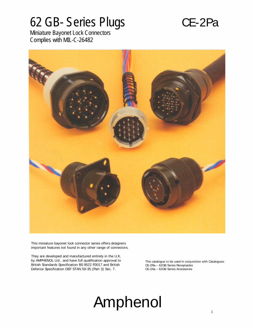
62 GB- Series Plugs Miniature Bayonet Lock Connectors Complies with MIL-C-26482
CE-2Pa
This miniature bayonet lock connector series offers designers important features not found in any other range of connectors. They are developed and manufactured entirely in the U.K. by AMPHENOL Ltd., and have full qualification approval to British Standards Specification BS 9522 F0017 and British Defence Specification DEF STAN 59-35 (Part 3) Sec. 7.
Amphenol
This catalogue to be used in conjunction with Catalogues: CE-2Ra – 62GB Series Receptacles CE-2Aa – 62GB Series Accessories
2
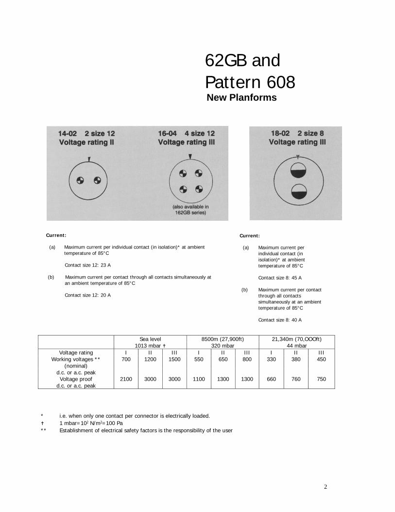
62GB and Pattern 608 New Planforms
Current:
(a) Maximum current per individual contact (in isolation)* at ambient temperature of 85°C
Contact size 12: 23 A
(b) Maximum current per contact through all contacts simultaneously at
an ambient temperature of 85°C
Contact size 12: 20 A
Current:
(a) Maximum current per individual contact (in isolation)* at ambient temperature of 85°C
Contact size 8: 45 A
(b) Maximum current per contact
through all contacts simultaneously at an ambient temperature of 85°C
Contact size 8: 40 A
Sea level 8500m (27,900ft) 21,340m (70,OOOft) 1013 mbar 320 mbar 44 mbar
Voltage rating I II III I II III I II III Working voltages ** 700 1200 1500 550 650 800 330 380 450
(nominal) d.c. or a.c. peak Voltage proof 2100 3000 3000 1100 1300 1300 660 760 750
d.c. or a.c. peak
* i.e. when only one contact per connector is electrically loaded. 1 mbar=102 N/m2=100 Pa
** Establishment of electrical safety factors is the responsibility of the user
CONTENTS Page Amphenol 62GB Solder Connectors 4
Schedule of Tests 5-6
Connector Styles Available 7
Insert Availability 8
Ordering 62GB Series Connectors 10-11
Plugs - Table of Styles 12-13
Plugs 14-19
Insert Orientations 20
Key/Keyway Orientations 21
4
Amphenol ® 62GB solder connectors
This miniature bayonet lock connector series offers designers important features not found in any other range of connectors. The range has full qualification approval to British Standards Specification BS 9522 FOO 17 and British Defence Specification DEF STAN 59-35 (Part 3) Sec. 7.
62GB Series connectors - developed and manufactured
entirely in the United Kingdom by Amphenol Limited. They are the first and only British connectors to have achieved this. A doubly strong position which Amphenol are well geared to handle. The manufacturing facilities of the Whitstable plant have been cited as exemplary in Europe. Certainly the layout is extensive and extremely efficient; safety awards have been attained every time returns have been submitted to the British Safety Council.
62GB Series connectors have been well established with
Government authorities on an international scale and users can be found in Sweden, Denmark, Norway, Finland, Germany, Spain, Holland, India, Canada and Italy.
Derating
Connectors must be derated under the following operating conditions:
1. At elevated ambient temperatures, the current ratings
are reduced so that total maximum hot spot temperature of 125°C is not exceeded.
2. At high altitudes, revised voltage ratings become
effective as shown on page 7. 3. When connectors to different specifications are
intermated (e.g. BS 9522 FOO 17 and MIL-C26482), the combination must not be operated under conditions more severe than the less stringent clause of either specification.
Amphenol 62GB connectors are designed to meet the most stringent requirements of both specifications.
Military Specifications
British Standards Specification BS 9522 FOO 17 closely corresponds to the United States Military Specification MIL-C-26482 solder terminations. Certain differences exist between the schedules which can be seen on pages 2 and 3.
Approved gauges are used to check interchangeability of 62GB series with other connectors manufactured to BS 9522 FOO 17 or MIL-C-26482.
Basic Construction 62GB Series can be supplied in brass or stainless steel. The normal shell finish used, which has a high resistance to corrosion, is zinc cobalt olive drab. Other finishes may be supplied to special order, such as cadmium plate which is available by adding deviation (714) to the end of part number. Inserts are of polychloroprene rubber compounded to an Amphenol specification. Operating temperature range is -55°C to 125°C, and the connectors have gold-plated contacts designed for soldered connections. Configurations for size 20 contacts range between 2 contacts in the size 8 12.7mm (0.5in diameter) shell up to a maximum of 61 contacts in the size 2436.1 mm (1.5in diameter) shell. Intermediate sizes, and contact data for heavier current ratings are shown in the insert availability chart on page 6 and 7.
Hermetic connectors with glass sealed dialectric are manufactured with mild steel shells and nickel iron contacts plated tin over copper.
* Other finishes are available on request. Protection Against Mis-Mating or Cross-Plugging
In BS 9522 FOO 17 positive shell-to-shell keying is provided with keys and keyways in a choice of either the normal (N) or any of the four preferred alternate positions: B, C, E and F. This prevents mismating between shells of different orientations and overcomes the difficulties associated with rotated inserts and a standard key-keyway orientation. In the latter system, damage to the inserts or contacts can result if excessive force is used to engage non-mating pairs.
Rotated inserts are, however, permissible in BS 9522 FOO 17 connectors if required to mate with or replace units to MIL-C-26482 mounted in existing equipment. Connectors have normal orientations manufactured to BS 9522 FOO 17 or MIL-C-26482 are fully intermateable as also are connectors with inserts in positions W, X, Y or Z.
This catalogue to be used in conjunction with Catalogues: CE-2Ra – 62GB Series Receptacles CE-2Aa – 62GB Series Accessories
5
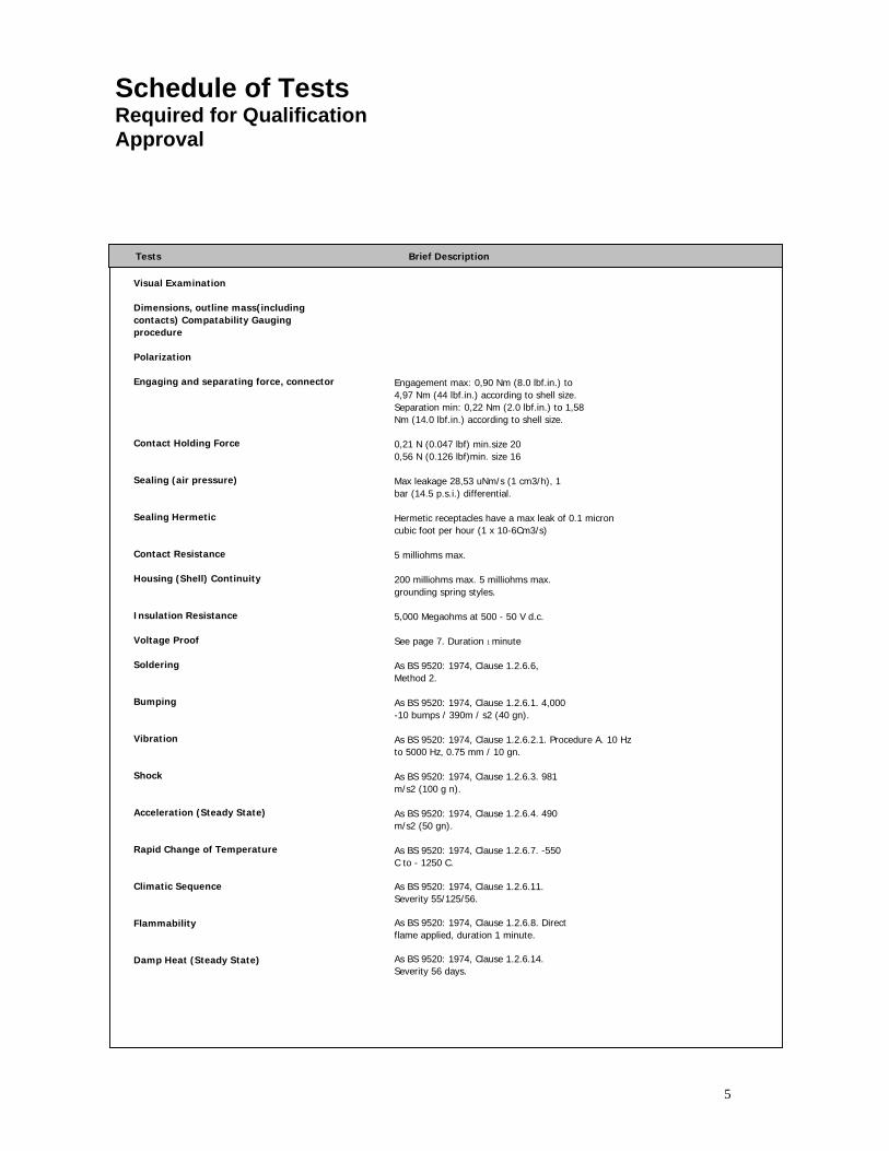
Schedule of Tests Required for Qualification Approval
Tests
Visual Examination Dimensions, outline mass(including contacts) Compatability Gauging procedure Polarization Engaging and separating force, connector Contact Holding Force Sealing (air pressure) Sealing Hermetic Contact Resistance Housing (Shell) Continuity Insulation Resistance Voltage Proof Soldering Bumping Vibration Shock Acceleration (Steady State) Rapid Change of Temperature Climatic Sequence Flammability Damp Heat (Steady State)
Brief Description
Engagement max: 0,90 Nm (8.0 lbf.in.) to 4,97 Nm (44 lbf.in.) according to shell size. Separation min: 0,22 Nm (2.0 lbf.in.) to 1,58 Nm (14.0 lbf.in.) according to shell size. 0,21 N (0.047 lbf) min.size 20 0,56 N (0.126 lbf)min. size 16 Max leakage 28,53 uNm/s (1 cm3/h), 1 bar (14.5 p.s.i.) differential. Hermetic receptacles have a max leak of 0.1 micron cubic foot per hour (1 x 10⁻⁶Cm3/s) 5 milliohms max. 200 milliohms max. 5 milliohms max. grounding spring styles. 5,000 Megaohms at 500 - 50 V d.c. See page 7. Duration 1 minute As BS 9520: 1974, Clause 1.2.6.6, Method 2. As BS 9520: 1974, Clause 1.2.6.1. 4,000 -10 bumps / 390m / s2 (40 gn). As BS 9520: 1974, Clause 1.2.6.2.1. Procedure A. 10 Hz to 5000 Hz, 0.75 mm / 10 gn. As BS 9520: 1974, Clause 1.2.6.3. 981 m/s2 (100 g n). As BS 9520: 1974, Clause 1.2.6.4. 490 m/s2 (50 gn). As BS 9520: 1974, Clause 1.2.6.7. -550 C to - 1250 C. As BS 9520: 1974, Clause 1.2.6.11. Severity 55/125/56. As BS 9520: 1974, Clause 1.2.6.8. Direct flame applied, duration 1 minute. As BS 9520: 1974, Clause 1.2.6.14. Severity 56 days.
6
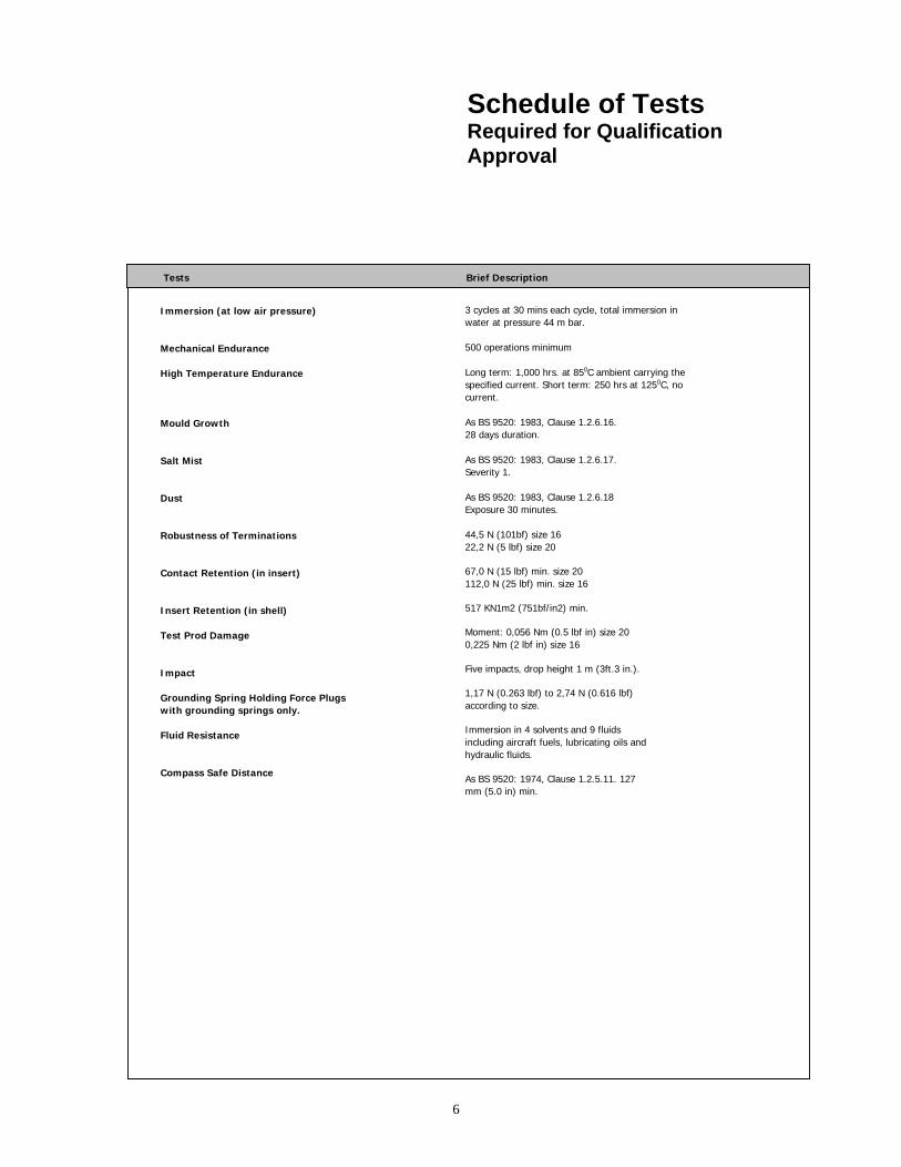
Schedule of Tests Required for Qualification Approval
Tests Brief Description
Immersion (at low air pressure) Mechanical Endurance High Temperature Endurance Mould Growth Salt Mist Dust Robustness of Terminations Contact Retention (in insert) Insert Retention (in shell) Test Prod Damage Impact Grounding Spring Holding Force Plugs with grounding springs only. Fluid Resistance Compass Safe Distance
3 cycles at 30 mins each cycle, total immersion in water at pressure 44 m bar. 500 operations minimum Long term: 1,000 hrs. at 850C ambient carrying the specified current. Short term: 250 hrs at 1250C, no current. As BS 9520: 1983, Clause 1.2.6.16. 28 days duration. As BS 9520: 1983, Clause 1.2.6.17. Severity 1. As BS 9520: 1983, Clause 1.2.6.18 Exposure 30 minutes. 44,5 N (101bf) size 16 22,2 N (5 lbf) size 20 67,0 N (15 lbf) min. size 20 112,0 N (25 lbf) min. size 16 517 KN1m2 (751bf/in2) min. Moment: 0,056 Nm (0.5 lbf in) size 20 0,225 Nm (2 lbf in) size 16 Five impacts, drop height 1 m (3ft.3 in.). 1,17 N (0.263 lbf) to 2,74 N (0.616 lbf) according to size. Immersion in 4 solvents and 9 fluids including aircraft fuels, lubricating oils and hydraulic fluids. As BS 9520: 1974, Clause 1.2.5.11. 127 mm (5.0 in) min.
7
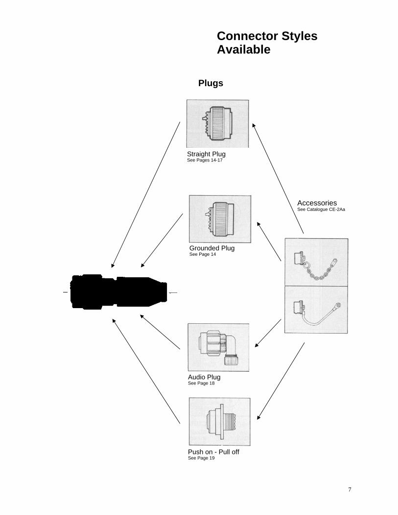
Connector Styles Available
Plugs
Straight PlugSee Pages 14-17
Grounded PlugSee Page 14
AccessoriesSee Catalogue CE-2Aa
Audio PlugSee Page 18
Push on - Pull offSee Page 19
8
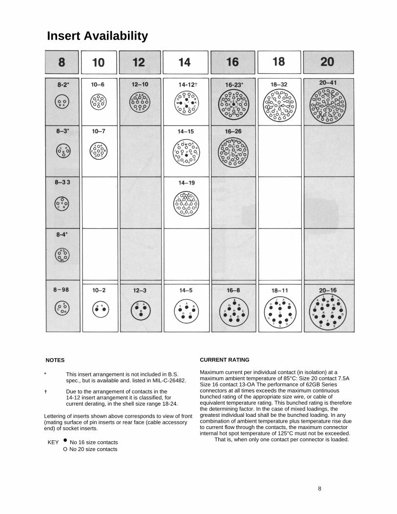
Insert Availability
NOTES * This insert arrangement is not included in B.S.
spec., but is available and. listed in MIL-C-26482.
Due to the arrangement of contacts in the 14-12 insert arrangement it is classified, for current derating, in the shell size range 18-24.
Lettering of inserts shown above corresponds to view of front (mating surface of pin inserts or rear face (cable accessory end) of socket inserts.
KEY • No 16 size contacts O No 20 size contacts
CURRENT RATING Maximum current per individual contact (in isolation) at a maximum ambient temperature of 85°C: Size 20 contact 7.5A Size 16 contact 13-OA The performance of 62GB Series connectors at all times exceeds the maximum continuous bunched rating of the appropriate size wire, or cable of equivalent temperature rating. This bunched rating is therefore the determining factor. In the case of mixed loadings, the greatest individual load shall be the bunched loading. In any combination of ambient temperature plus temperature rise due to current flow through the contacts, the maximum connector internal hot spot temperature of 125°C must not be exceeded.
That is, when only one contact per connector is loaded.
9
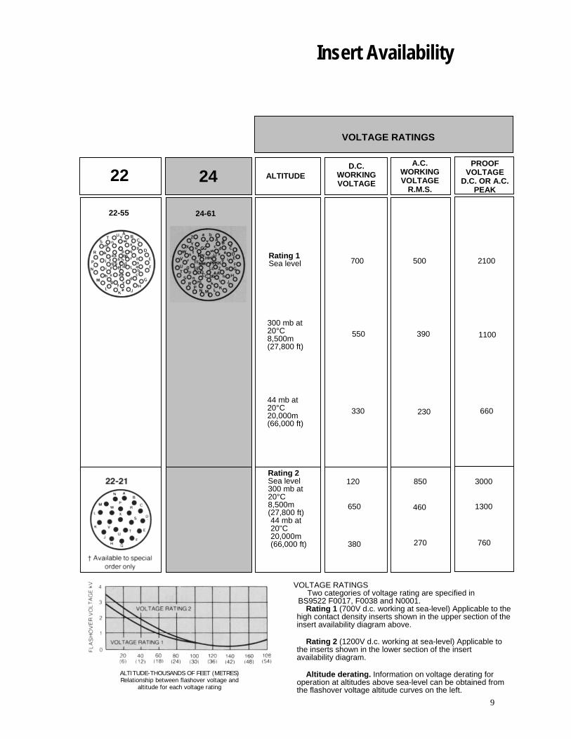
Insert Availability
VOLTAGE RATINGS
ALTITUDE-THOUSANDS OF FEET (METRES)Relationship between flashover voltage and
altitude for each voltage rating
VOLTAGE RATINGSTwo categories of voltage rating are specified in
BS9522 F0017, F0038 and N0001. Rating 1 (700V d.c. working at sea-level) Applicable to the
high contact density inserts shown in the upper section of the insert availability diagram above.
Rating 2 (1200V d.c. working at sea-level) Applicable to
the inserts shown in the lower section of the insert availability diagram.
Altitude derating. Information on voltage derating for
operation at altitudes above sea-level can be obtained from the flashover voltage altitude curves on the left.
22
22-55
D.C.WORKING VOLTAGE
A.C. WORKING VOLTAGE
R.M.S.
PROOFVOLTAGE
D.C. OR A.C. PEAK
Rating 1Sea level
300 mb at 20°C 8,500m (27,800 ft)
44 mb at 20°C 20,000m (66,000 ft)
Rating 2Sea level 300 mb at 20°C 8,500m (27,800 ft) 44 mb at 20"C 20,000m (66,000 ft)
700
550
330
120
650
380
500
390
230
850
460
270
2100
1100
660
3000
1300
760
24 ALTITUDE
24-61
10
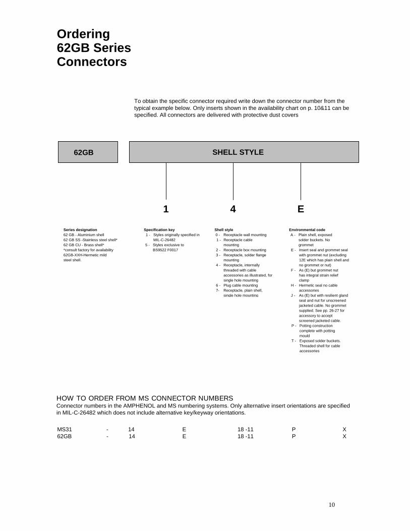
Ordering 62GB Series Connectors
To obtain the specific connector required write down the connector number from the typical example below. Only inserts shown in the availability chart on p. 10&11 can be specified. All connectors are delivered with protective dust covers
62GB SHELL STYLE
1 4 E
Environmental code A - Plain shell, exposed
solder buckets. No grommet
E - Insert seal and grommet seal with grommet nut (excluding 12E which has plain shell and no grommet or nut)
F - As (E) but grommet nut has integral strain relief clamp
H - Hermetic seal no cable accessories
J - As (E) but with resilient gland seal and nut for unscreened jacketed cable. No grommet supplied. See pp. 26-27 for accessory to accept screened jacketed cable.
P - Potting construction complete with potting mould
T - Exposed solder buckets. Threaded shell for cable accessories
Shell style 0 - Receptacle wall mounting 1 - Receptacle cable
mounting 2 - Receptacle box mounting 3 - Receptacle, solder flange
mounting 4 - Receptacle, internally
threaded with cable accessories as illustrated, for single hole mounting
6 - Plug cable mounting 7- Receptacle, plain shell,
single hole mounting
Specification key 1 - Styles originally specified in
MIL-C-26482 5 - Styles exclusive to
BS9522 F0017
Series designation 62 GB - Aluminium shell 62 GB SS -Stainless steel shell* 62 GB CU - Brass shell* *consult factory for availability 62GB-XXH-Hermetic mild steel shell.
HOW TO ORDER FROM MS CONNECTOR NUMBERS Connector numbers in the AMPHENOL and MS numbering systems. Only alternative insert orientations are specified in MIL-C-26482 which does not include alternative key/keyway orientations.
MS31 - 14 E 18 -11 P X 62GB - 14 E 18 -11 P X
11
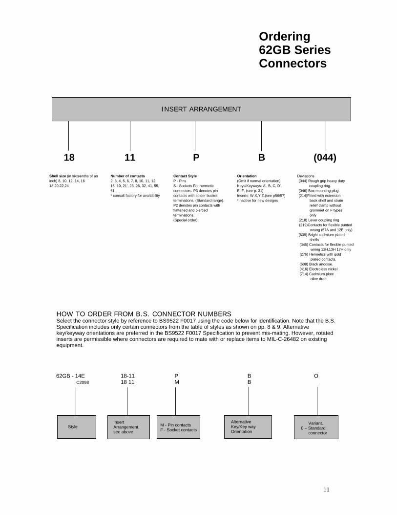
Ordering 62GB Series Connectors
INSERT ARRANGEMENT
18 11 P B (044) Shell size (in sixteenths of an inch) 8, 10, 12, 14, 16 18,20,22,24
Number of contacts 2, 3, 4, 5, 6, 7, 8, 10, 11, 12, 16, 19, 21', 23, 26, 32, 41, 55, 61 * consult factory for availability
Contact Style P - Pins S - Sockets For hermetic connectors. P3 denotes pin contacts with solder bucket terminations. (Standard range). P2 denotes pin contacts with flattened and pierced terminations. (Special order).
Orientation (Omit if normal orientation) Keys/Keyways: A', B, C, D', E. F, (see p. 31) Inserts: W,X,Y,Z.(see p56/57) *Inactive for new designs
Deviations (044) Rough grip heavy duty
coupling ring. (046) Box mounting plug. (214)Fitted with extension
back shell and strain relief clamp without grommet on F types only
(218) Lever coupling ring (219)Contacts for flexible punted
wrung (57A and 12E only) (639) Bright cadmium plated
shells (345) Contacts for flexible punted
wiring 12H,13H 17H only (276) Hermetics with gold
plated contacts. (608) Black anodise. (416) Electroless nickel (714) Cadmium plate
olive drab
HOW TO ORDER FROM B.S. CONNECTOR NUMBERS Select the connector style by reference to BS9522 F0017 using the code below for identification. Note that the B.S. Specification includes only certain connectors from the table of styles as shown on pp. 8 & 9. Alternative key/keyway orientations are preferred in the BS9522 F0017 Specification to prevent mis-mating. However, rotated inserts are permissible where connectors are required to mate with or replace items to MIL-C-26482 on existing equipment.
62GB - 14E C2098
18-11 18 11
PM
B B
O
Style Insert Arrangement, see above
M - Pin contacts F - Socket contacts
Alternative Key/Key way Orientation
Variant. 0 – Standard
connector
12
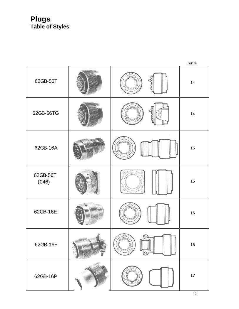
Plugs Table of Styles
62GB-56T
62GB-56TG
62GB-16A
62GB-56T (046)
62GB-16E
62GB-16F
62GB-16P
Page No.
14
14
15
15
16
16
17
13
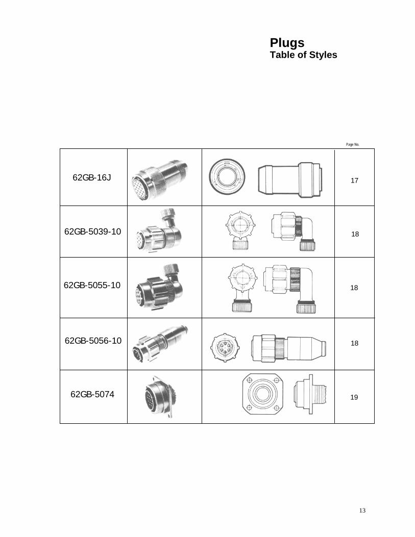
Plugs Table of Styles
62GB-16J
62GB-5039-10
62GB-5055-10
62GB-5056-10
62GB-5074
Page No.
17
18
18
18
19
14
Plugs
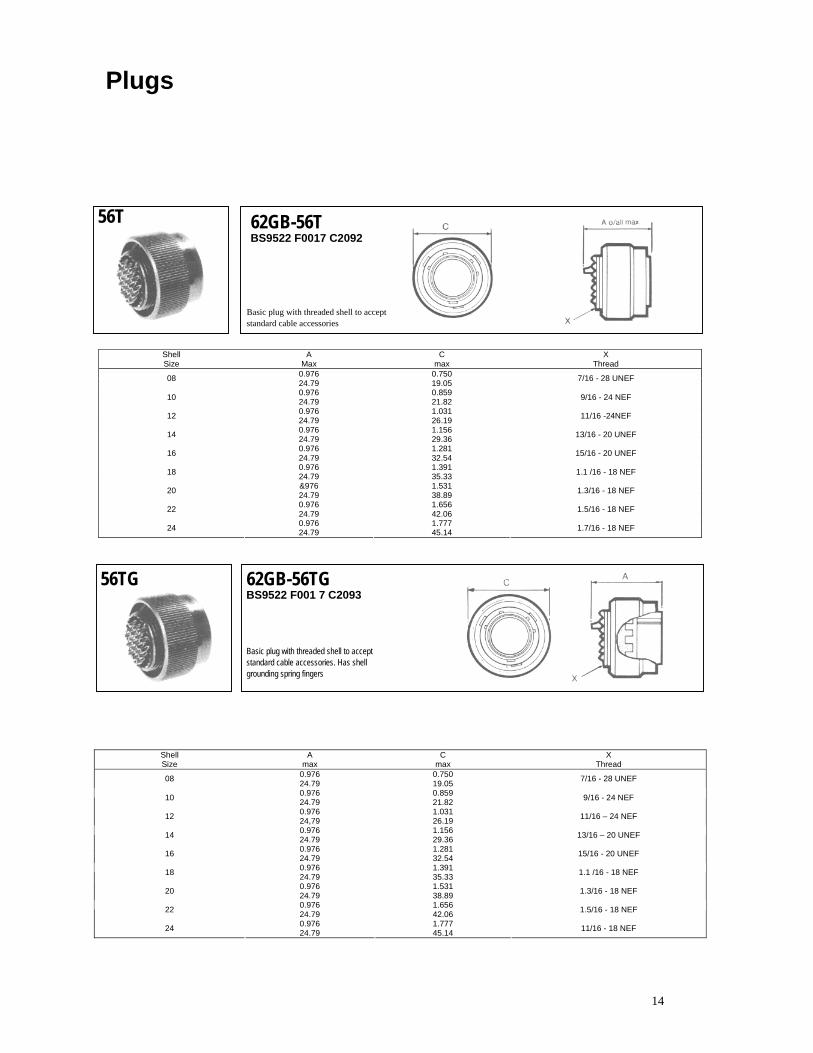
56T 62GB-56T BS9522 F0017 C2092
Basic plug with threaded shell to accept standard cable accessories
Shell Size
A Max
C max
X Thread
0.976 0.750 08 24.79 19.05 7/16 - 28 UNEF
0.976 0.859 10 24.79 21.82 9/16 - 24 NEF
0.976 1.031 12 24.79 26.19 11/16 -24NEF
0.976 1.156 14 24.79 29.36 13/16 - 20 UNEF
0.976 1.281 16 24.79 32.54 15/16 - 20 UNEF
0.976 1.391 18 24.79 35.33 1.1 /16 - 18 NEF
&976 1.531 20 24.79 38.89 1.3/16 - 18 NEF
0.976 1.656 22 24.79 42.06 1.5/16 - 18 NEF
0.976 1.777 24 24.79 45.14 1.7/16 - 18 NEF
56TG 62GB-56TG BS9522 F001 7 C2093
Basic plug with threaded shell to accept standard cable accessories. Has shell grounding spring fingers
Shell Size
A max
C max
X Thread
0.976 0.750 08 24.79 19.05 7/16 - 28 UNEF
0.976 0.859 10 24.79 21.82 9/16 - 24 NEF
0.976 1.031 12 24,79 26.19 11/16 – 24 NEF
0.976 1.156 14 24.79 29.36 13/16 – 20 UNEF
0.976 1.281 16 24.79 32.54 15/16 - 20 UNEF
0.976 1.391 18 24.79 35.33 1.1 /16 - 18 NEF
0.976 1.531 20 24.79 38.89 1.3/16 - 18 NEF
0.976 1.656 22 24.79 42.06 1.5/16 - 18 NEF
0.976 1.777 24 24.79 45.14 11/16 - 18 NEF
15
Plugs
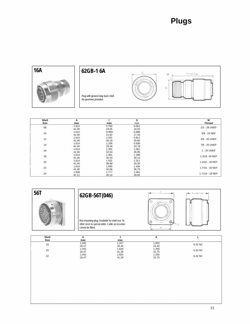
16A 62GB-1 6A
Plug with general duty back shell. No grommet provided.
Shell Size
A max
C max
G max
M Thread
1.614 0.750 0.561 08 41.00 19.05 14.25 1/2 - 28 UNEF
1.614 O.859 0,686 10 41.00 21.82 17.43 5/8 - 24 NEF
1.614 1.031 0.811 12 41.00 26.19 20.60 3/4 - 20 UNEF
1.614 1,156 0.936 14 41.00 29.36 23.78 7/8 - 20 UNEF
1.614 1.281 1.061 16 41.00 32.54 26.95 1 - 20 UNEF
1.614 1.391 1.186 18 41.00 35.33 30.13 1.3/16 -18 NEF
1.614 1.531 1.311 20 41.00 38-89 33.30 1.3/16 - 18 NEF
1.614 1.656 1.436 22 41.00 42.06 36.75 1.7/16 - 18 NEF
1.658 1.777 1.561 24 42.11 45.14 39.65 1.7116 - 18 NEF
56T 62GB-56T(046)
Box-mounting plug. Available for shell size 16: other sizes to special order. Cable accessories cannot be fitted.
Shell Size
A max
J max
K L
1.042 1.317 1,000 16 26.47 33.45 25.40 6.32 NC
1.042 1.625 1.250 20 26.47 41.28 31.75 6.32 NC
1.042 1.625 1.250 22 26.47 41.28 31.75 6.32 NC
16
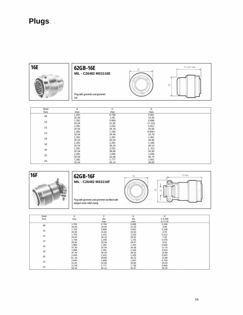
16E 62GB-16E MIL - C26482 MS3116E
Plug with grommet and grommet nut
Shell Size
A max
C max
G max
1.281 0.750 0.561 08 32.54 1.05 14.25 1.281 0.859 0.686 10 32.54 21.82 17.431 1.281 1.031 0.811 12 32.54 26.19 20.60 1.281 1.156 0.936 I 14 32.54 29.36 23.78 1.281 1.281 1.061 16 32.54 32.54 26.95 1.281 1.391 1.186 18 32.54 35.33 30.13 1.281 1.531 1 .311 20 32.54 38.89 33.30 1.281 1.656 1.436 22 32.54 42.06 36.75 1.281 1.777 1.561 24 32.54 45.14 39.65
16F 62GB-16F MIL - C26482 MS3116F
Plug with grommet and grommet nut fitted with integral strain relief clamp.
Shell Size
A max
C dia max
G dia
max
H ± 0.005 (± 0.13)
1.752 0.750 0.828 0.156 08 44.50 19.05 21.03 3.96 1.752 0.859 0.891 0.188 10 44.50 21.82 22.63 4.78 1.752 1.031 1.016 0.312 12 44.50 26.19 25.81 7.93 1.726 1.156 1.141 0.375 14 43.84 29.36 28.97 9.53 1.866 1.281 1.203 0.500 16 47.40 32.54 30.56 12.70 1.866 1.391 1.426 0.625 18 47.40 35.33 36.22 15.88 2.040 1.531 1.426 0.625 20 51 .81 38.89 36.22 15.88 2.040 1.656 1.567 0.750 22 51.81 42.06 39.80 19.05 2.178 1.777 1.735 0.800 24 55.32 45.14 44.07 20.32
Plugs
17
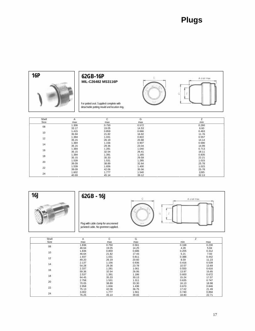
16P 62GB-16P
MIL-C26482 MS3116P
For potted seal. Supplied complete with detachable potting mould and location ring.
Shell Size
A max
C max
G max
Z min
1.306 0.750 0.572 0.260 08 33.17 19.05 14.53 6.60 1.415 0.859 0.666 0.463 10 35.94 21.82 16.92 11.76 1.384 1.031 0.822 0.557 12 35.15 26.19 20.88 14.14 1.384 1.156 0.907 0.590 14 35.15 29.36 23.04 14.99 1.384 1.281 1.040 0.713 16 35.15 32.54 26.41 18.11 1.384 1.391 1.165 0.835 18 35.15 35.33 29.59 22.21 1.539 1.531 1.285 1.015 20 39.09 38.89 32.64 25.78 1.539 1.656 1.400 1.015 22 39.09 42.06 35.56 25.78 1.602 1.777 1.540 1265 24 40.69 45.14 39.12 32.13
16J 62GB - 16J
Plug with cable clamp for unscreened jacketed cable. No grommet supplied.
Shell Size
A max
C max
G max
Z min max
1.836 0.750 0.561 0.168 0.230 08 46.64 19.05 14.25 4.28 5.841.836 0.859 0.686 0.205 0.312 10 46.64 21.82 17.43 5.21 7.93 1.937 1.031 0.811 0.388 0.442 12 49.20 26.19 20.60 8.59 11.23 2.137 1.156 0.936 0.416 0.539 14 54.28 29.36 23.78 10.57 13.692.337 1.281 1.061 0.550 0.616 16 59.36 32.54 26.95 13.97 15.65 2.537 1.391 1.186 0.600 0.672 18 64.45 35.33 30.13 15.24 17.07 2.758 1.531 1.311 0.635 0.747 20 70.05 38.89 33.30 16.13 18.982.958 1.656 1.436 0.670 0.846 22 75.13 42.06 36.75 17.02 21.493.002 1.777 1.561 0.740 0.894 24 76.25 45.14 39.65 18.80 22.71
Plugs
18
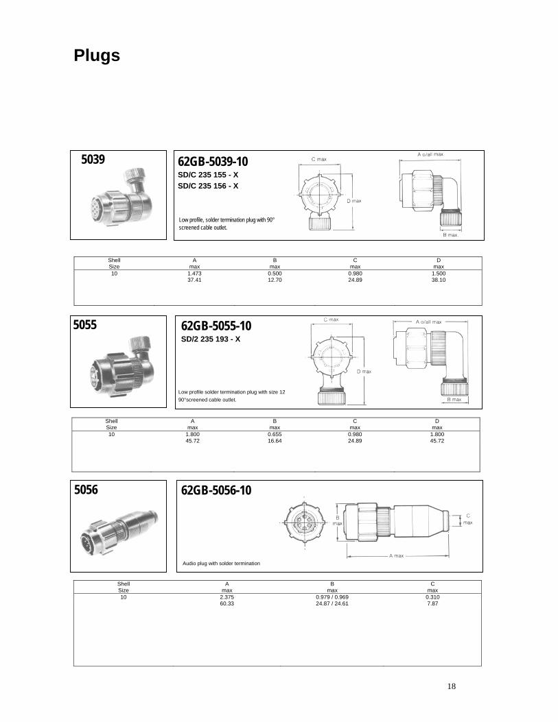
5039 62GB-5039-10 SD/C 235 155 - X SD/C 235 156 - X
Low profile, solder termination plug with 90° screened cable outlet.
Shell Size
A max
B max
C max
D max
10 1.473 0.500 0.980 1.500 37.41 12.70 24.89 38.10
5055 62GB-5055-10 SD/2 235 193 - X
Low profile solder termination plug with size 12 90°screened cable outlet.
Shell A B C D Size max max max max 10 1.800 0.655 0.980 1.800
45.72 16.64 24.89 45.72
5056 62GB-5056-10
Audio plug with solder termination
Shell Size
A max
B max
C max
10 2.375 0.979 / 0.969 0.310 60.33 24.87 / 24.61 7.87
Plugs
19
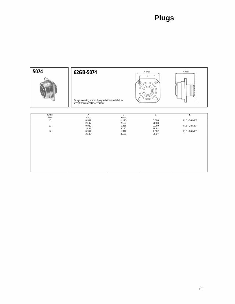
5074 62GB-5074
Flange mounting push/pull plug with threaded shell to accept standard cable accessories.
Shell Size
A max
B max
C L
10 0.912 1.125 0.866 9/16 - 24 NEF 23.17 28.57 22.00
12 0.912 1.218 0.969 9/16 - 24 NEF 23.17 30.93 24.61
14 0.912 1.312 1.062 9/16 - 24 NEF 23.17 33.32 26.97
Plugs
20
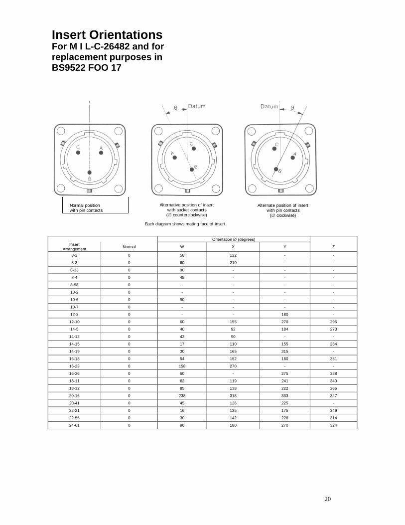
Insert Orientations For M I L-C-26482 and for replacement purposes in BS9522 FOO 17
Normal position with pin contacts
Alternative position of insertwith socket contacts (∅ counterclockwise)
Each diagram shows mating face of insert.
Alternate position of insert with pin contacts
(∅ clockwise)
Orientation ∅ (degrees) Insert
Arrangement Normal W X Y Z
8-2 0 58 122 - -
8-3 0 60 210 - -
8-33 0 90 - - -
8-4 0 45 - - -
8-98 0 - - - -
10-2 0 - - - -
10-6 0 90 - - -
10-7 0 - - - -
12-3 0 - - 180 -
12-10 0 60 155 270 295
14-5 0 40 92 184 273
14-12 0 43 90 - -
14-15 0 17 110 155 234
14-19 0 30 165 315 -
16-18 0 54 152 180 331
16-23 0 158 270 - -
16-26 0 60 - 275 338
18-11 0 62 119 241 340
18-32 0 85 138 222 265
20-16 0 238 318 333 347
20-41 0 45 126 225 -
22-21 0 16 135 175 349
22-55 0 30 142 226 314
24-61 0 90 180 270 324
21
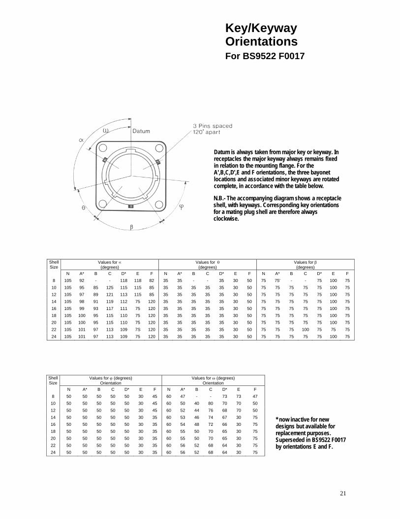
Key/Keyway Orientations For BS9522 F0017
Datum is always taken from major key or keyway. In receptacles the major keyway always remains fixed in relation to the mounting flange. For the A',B,C,D',E and F orientations, the three bayonet locations and associated minor keyways are rotated complete, in accordance with the table below.
N.B.- The accompanying diagram shows a receptacle shell, with keyways. Corresponding key orientations for a mating plug shell are therefore always clockwise.
Shell Size Values for ∝
(degrees) Values for θ (degrees) Values for β
(degrees)
N A* B C D* E F N A* B C D* E F N A* B C D* E F 8 105 92 - - 118 118 82 35 35 - - 35 30 50 75 75' - - 75 100 75
10 105 95 85 125 115 115 85 35 35 35 35 35 30 50 75 75 75 75 75 100 75 12 105 97 89 121 113 115 85 35 35 35 35 35 30 50 75 75 75 75 75 100 75 14 105 98 91 119 112 75 120 35 35 35 35 35 30 50 75 75 75 75 75 100 75 16 105 99 93 117 111 75 120 35 35 35 35 35 30 50 75 75 75 75 75 100 75 18 105 100 95 115 110 75 120 35 35 35 35 35 30 50 75 75 75 75 75 100 75 20 105 100 95 115 110 75 120 35 35 35 35 35 30 50 75 75 75 75 75 100 75 22 105 101 97 113 109 7S 120 35 35 35 35 35 30 50 75 75 75 100 75 75 75 24 105 101 97 113 109 75 120 35 35 35 35 35 30 50 75 75 75 75 75 100 75
Shell Size
Values for ϕ (degrees) Orientation
Values for ω (degrees) Orientation
N A* B C D* E F N A* B C D* E F 8 50 50 50 50 50 30 45 60 47 - - 73 73 47 10 50 50 50 50 50 30 45 60 50 40 80 70 70 50 12 50 50 50 50 50 30 45 60 52 44 76 68 70 50 14 50 50 50 50 50 30 35 60 53 46 74 67 30 75 16 50 50 50 50 50 30 35 60 54 48 72 66 30 75 18 50 50 50 50 50 30 35 60 55 50 70 65 30 75 20 50 50 50 50 50 30 35 60 55 50 70 65 30 75 22 50 50 50 50 50 30 35 60 56 52 68 64 30 75 24 50 50 50 50 50 30 35 60 56 52 68 64 30 75
* now inactive for new designs but available for replacement purposes. Superseded in BS9522 F0017 by orientations E and F.

22


