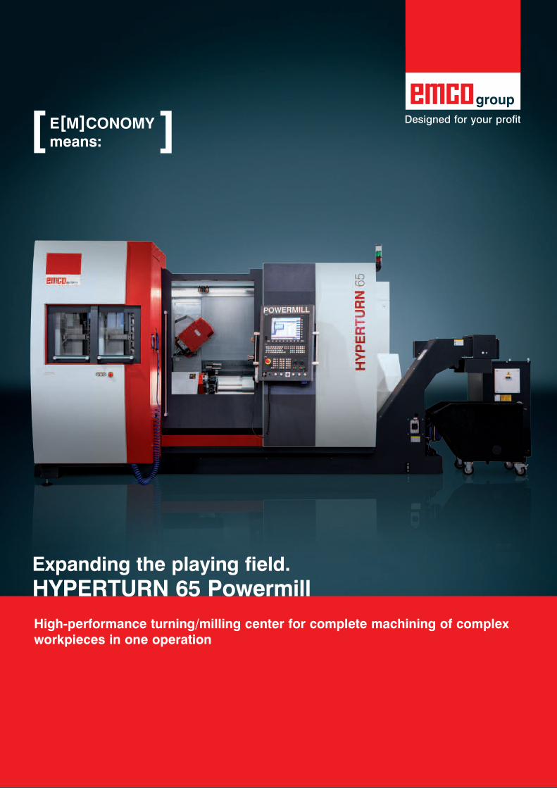
High-performance turning/milling center for complete machining of complex workpieces in one operation
E[M]CONOMymeans:[ ]
Expanding the playing field.HyPERTURN 65 Powermill

HyPERTURN 65 Powermill
More clearance, more power, more possibilities: with a spindle distance of 1300 mm, a powerful counter spindle which also allows 4‑axis machining, a B‑axis with a direct drive for complex 5‑axis simultaneous milling operations, an additional Y‑axis for the lower turret, and all proven, high‑quality features of the Hyperturn series, the Hyperturn 65 Powermill is a powerful addition to every machine range.
Machine with optional equipment
[ Main spindle]‑ Integrated spindle motor (ISM) in
synchronous technology ‑ water‑cooled‑ High drive power 29 (37) kW‑ High torque 250 (360) Nm‑ Large speed range
0 ‑ 5000 (4000/3500) rpm‑ Highly dynamic‑ Bar capacity diameter 65 (76/95) mm
[ Upper tool system]‑ Powerful milling spindle 29 kW‑ Wide speed range 0‑12000 rpm‑ Water‑cooled motor spindle with HSK‑T63 ‑ Internal and external coolant supply‑ B axis with zero backlash direct drive‑ B axis position can be fixed in any position
[ Lower y axis]‑ Travel +/‑ 50 mm‑ Stable, compact construction‑ Wide guide clearances‑ Tapered carriage system
[ Lower tool system]‑ 12‑station tool turret‑ VDI30‑ (VDI40‑ or BMT55P‑) quick‑change
system‑ 12 driven tool stations‑ Servo‑controlled‑ Rigid tapping‑ Polygonal turning, etc.
[ Tool magazine]‑ 20‑slot disc‑type tool magazine‑ 40/80/120‑slot chain‑type tool magazine‑ Ergonomically arranged up front‑ Easy to be manually loaded with tooling‑ Max. tool length 250 mm‑ Max. tool diameter 80 (120) mm‑ Max. tool weight 5 kg
[Upper y axis]‑ Large working stroke +120 / ‑100‑ Short cantilever length‑ Pre‑loaded roller guides‑ Wide guide clearance

Sprocket‑wheel (Steel Ck 45)
[Workpieces]
Bonnet flange (Brass)
Sensor housing (Stainless steel)
Knee (Steel 16 Mn Cr5)
[ Control unit]‑ Ergonomically designed ‑ 90° pivot and slidable‑ Siemens Sinumerik 840D sl‑ LCD color monitor 15‘‘
[ Counter spindle]‑ Integrated spindle motor (ISM) in
synchronous technology ‑ water‑cooled‑ High drive power 29 kW‑ High torque 250 Nm‑ Wide speed range 0‑5000 rpm‑ Coolant feed internal for flushing‑ Automatic part ejector
[ Work area ]‑ Generous design‑ Straight chip fall‑ Optimum access to the work area
[ Finished part conveyor]‑ Max. work piece size Ø 95 x 200 mm‑ Max. finished part weight 4,5 kg‑ Storage area 230 x 1000 mm
[ Chip conveyer]‑ Hinged type conveyor belt‑ Throw‑off height 1200 mm‑ Integrated coolant tank 400 l‑ Turret pumps: 2 x 14 bar‑ Flushing pumps: 2 x 3,7 bar
[Upper y axis]‑ Large working stroke +120 / ‑100‑ Short cantilever length‑ Pre‑loaded roller guides‑ Wide guide clearance

[Hyper-Flexibility]
Milling slant slots
Contour milling (elliptical)Hole patterns centering, drilling, tapping resp. grooving
3D free‑form milling
Undercut Form E/F
Turn‑milling of eccentrical diameter
Machine flexibility is often sacrificed for the sake of productivity. Not with the HYPERTURN: with its high‑performance and exceptionally mobile milling spindle and an almost inexhaustible tool magazine, the HYPERTURN can do nearly anything ‑ and very quickly.

Gear machining (gear hobbing)
Thread milling
Circular spitgot milling
I.D. threading
I.D. boring
Automated measuring in the workspace
Deep‑hole drilling
I.D. grooving
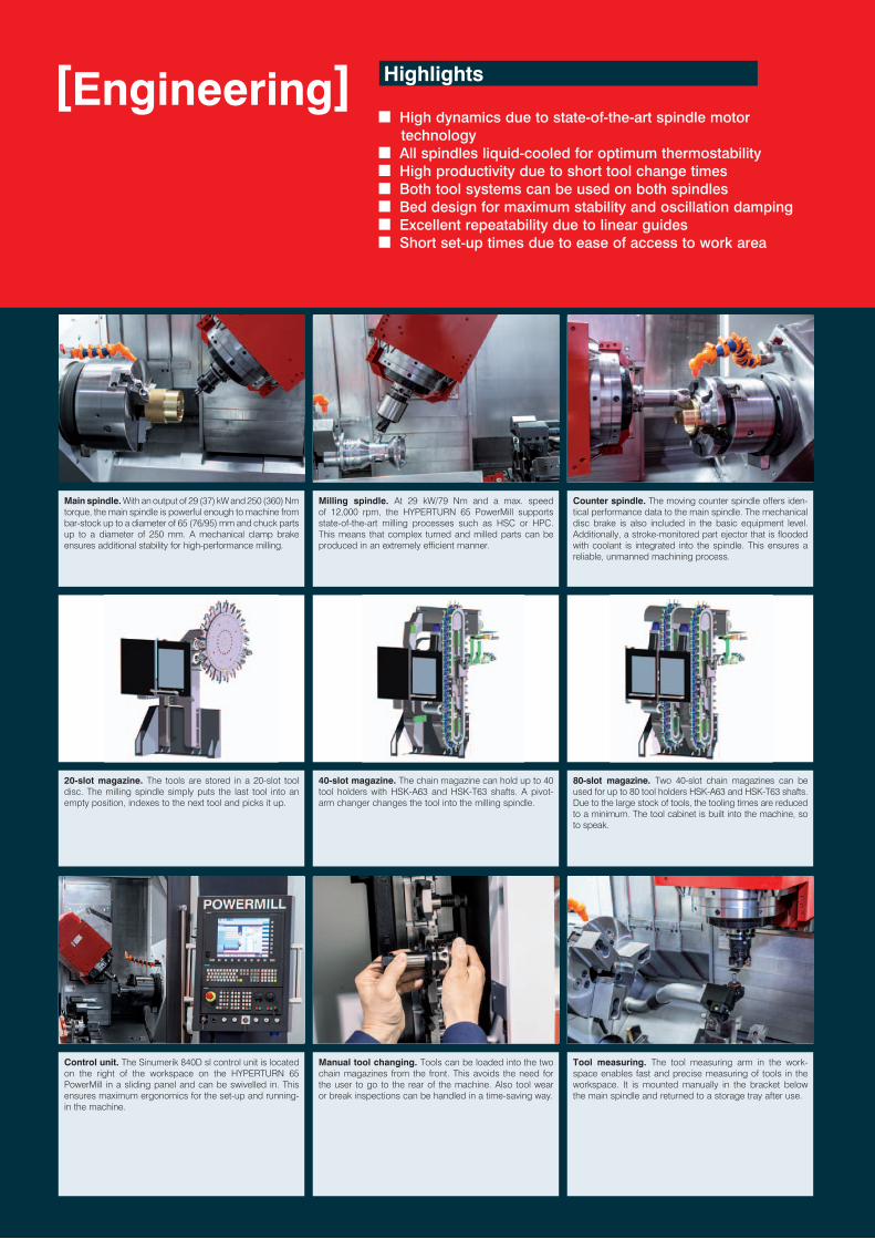
n High dynamics due to state‑of‑the‑art spindle motor technologyn All spindles liquid‑cooled for optimum thermostabilityn High productivity due to short tool change timesn Both tool systems can be used on both spindlesn Bed design for maximum stability and oscillation dampingn Excellent repeatability due to linear guidesn Short set‑up times due to ease of access to work area
[Engineering] Highlights
Main spindle. With an output of 29 (37) kW and 250 (360) Nmtorque, the main spindle is powerful enough to machine from bar-stock up to a diameter of 65 (76/95) mm and chuck parts up to a diameter of 250 mm. A mechanical clamp brake ensures additional stability for high-performance milling.
Milling spindle. At 29 kW/79 Nm and a max. speed of 12,000 rpm, the HYPERTURN 65 PowerMill supports state-of-the-art milling processes such as HSC or HPC. This means that complex turned and milled parts can be produced in an extremely efficient manner.
Counter spindle. The moving counter spindle offers iden-tical performance data to the main spindle. The mechanical disc brake is also included in the basic equipment level. Additionally, a stroke-monitored part ejector that is flooded with coolant is integrated into the spindle. This ensures a reliable, unmanned machining process.
40-slot magazine. The chain magazine can hold up to 40 tool holders with HSK-A63 and HSK-T63 shafts. A pivot-arm changer changes the tool into the milling spindle.
20-slot magazine. The tools are stored in a 20-slot tool disc. The milling spindle simply puts the last tool into an empty position, indexes to the next tool and picks it up.
80-slot magazine. Two 40-slot chain magazines can be used for up to 80 tool holders HSK-A63 and HSK-T63 shafts. Due to the large stock of tools, the tooling times are reduced to a minimum. The tool cabinet is built into the machine, so to speak.
Control unit. The Sinumerik 840D sl control unit is located on the right of the workspace on the HYPERTURN 65 PowerMill in a sliding panel and can be swivelled in. This ensures maximum ergonomics for the set-up and running-in the machine.
Manual tool changing. Tools can be loaded into the two chain magazines from the front. This avoids the need for the user to go to the rear of the machine. Also tool wear or break inspections can be handled in a time-saving way.
Tool measuring. The tool measuring arm in the work-space enables fast and precise measuring of tools in the workspace. It is mounted manually in the bracket below the main spindle and returned to a storage tray after use.
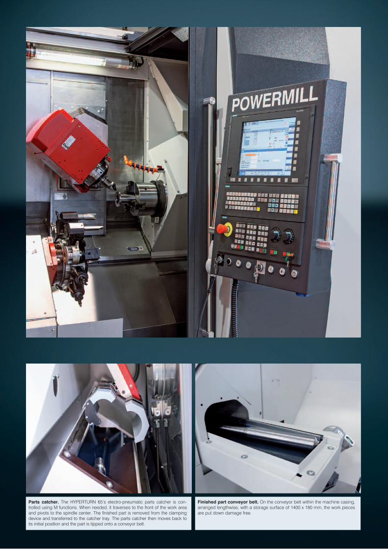
Parts catcher. The HYPERTURN 65’s electro-pneumatic parts catcher is con-trolled using M functions. When needed, it traverses to the front of the work area and pivots to the spindle center. The finished part is removed from the clamping device and transferred to the catcher tray. The parts catcher then moves back to its initial position and the part is tipped onto a conveyor belt.
Finished part conveyor belt. On the conveyor belt within the machine casing, arranged lengthwise, with a storage surface of 1400 x 180 mm, the work pieces are put down damage free.
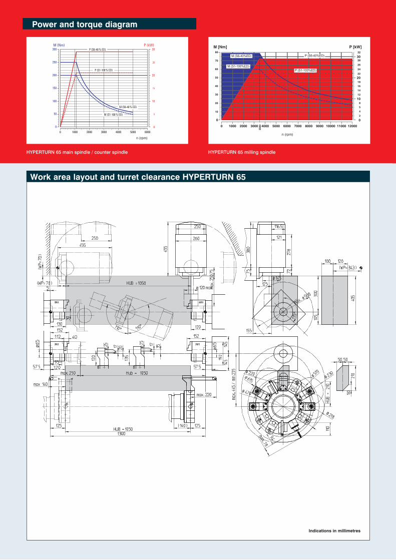
Power and torque diagram
HYPERTURN 65 main spindle / counter spindle HYPERTURN 65 milling spindle
Work area layout and turret clearance HyPERTURN 65
Indications in millimetres
00 1000 2000 3000 4000 5000 6000 7000
100
50
150
150
200 20
25
15
5
10
0
P (S6-40 % ED)
P (S1-100 % ED)
M (S6-40 % ED)
M (S1-100 % ED)
Leistung und Momentenverlauf HT 665 Hauptspindel
M (Nm)
0
0 1000 2000 3000 4000 5000 6000
100
50
150
250
200
300P (kW)
n (U/min)
30
20
25
15
5
10
0
P (S6-40 % ED)
P (S1-100 % ED)
M (S6-40 % ED)
M (S1-100 % ED)
M (Nm) P (kW)
n (U/min)
n (rpm)
Leistung und Momentenverlauf Powermill Frässpindel 12000
M [Nm]
0 1000 2000
35003000 4000 5000 6000 8000 9000 10000 11000 120007000
P [kW]
2
458
10
20
40
50
60
70
80
30 12
00
10
141618
22
24
26
28
20
3032
n [min-1]
M (S6-40%ED)
M (S1-100%ED)
P (S6-40%ED)
P (S1-100%ED)
n (rpm)
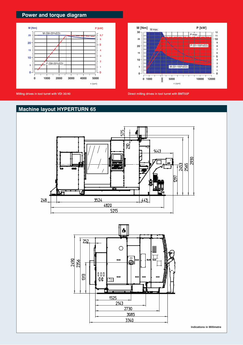
Power and torque diagram
Milling drives in tool turret with VDI 30/40 Direct milling drives in tool turret with BMT55P
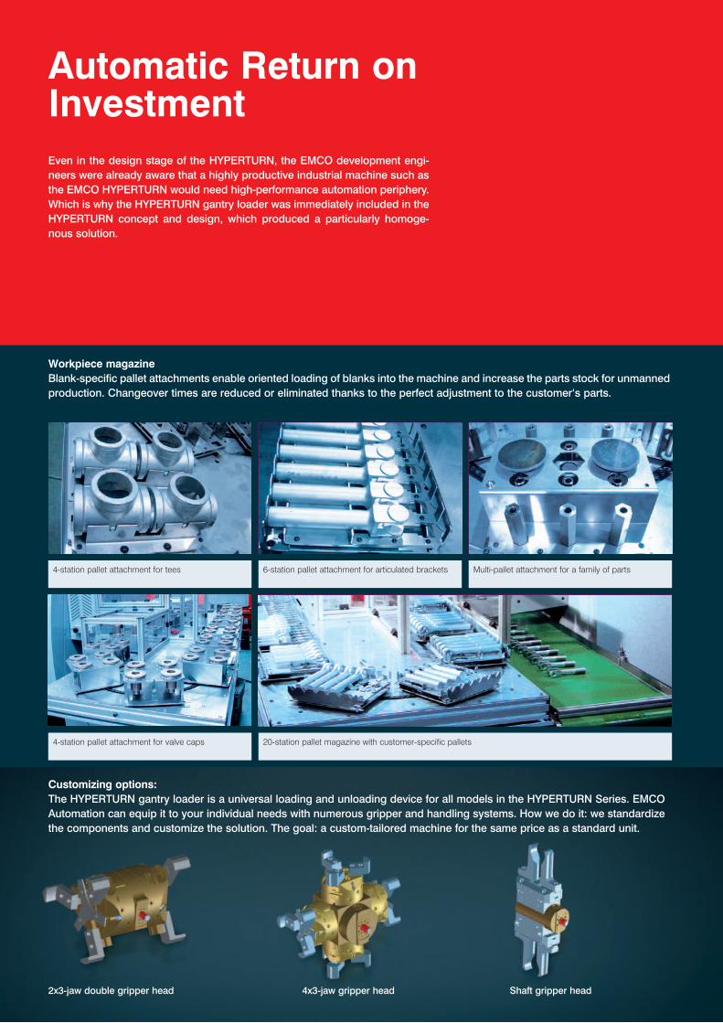
Machine layout HyPERTURN 65
Indications in Millimetre
Leistung und Momentenverlauf Werkzeugwender VDI30
M [Nm]
0 1000 2000 3000 4000 5000
P [kW]
1
2
3
4
5
15
2566,7
00
10
20 5
n [min-1]
P (S6-25%ED)
M (S6-25%ED)
n (rpm)
M [Nm]
0 1000 5000 10000 12000
P [kW]
6
4
32
3300
1
789
1112
5
15
25
0
5
10
0
10
20
30
n [min-1]
M (S1-100%ED)
M max.
P (S1-100%ED)
P max.
n (rpm)
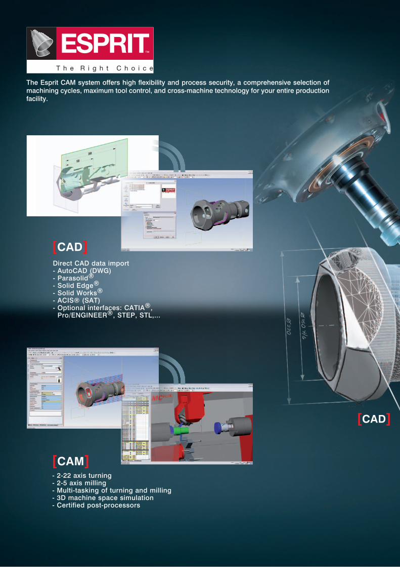
Automatic Return on Investment Even in the design stage of the HYPERTURN, the EMCO development engi‑neers were already aware that a highly productive industrial machine such as the EMCO HYPERTURN would need high‑performance automation periphery. Which is why the HYPERTURN gantry loader was immediately included in the HYPERTURN concept and design, which produced a particularly homoge‑nous solution.
Workpiece magazineBlank‑specific pallet attachments enable oriented loading of blanks into the machine and increase the parts stock for unmanned production. Changeover times are reduced or eliminated thanks to the perfect adjustment to the customer‘s parts.
4-station pallet attachment for tees 6-station pallet attachment for articulated brackets Multi-pallet attachment for a family of parts
4-station pallet attachment for valve caps 20-station pallet magazine with customer-specific pallets
Customizing options:The HYPERTURN gantry loader is a universal loading and unloading device for all models in the HYPERTURN Series. EMCO Automation can equip it to your individual needs with numerous gripper and handling systems. How we do it: we standardize the components and customize the solution. The goal: a custom‑tailored machine for the same price as a standard unit.
2x3‑jaw double gripper head 4x3‑jaw gripper head Shaft gripper head

Pivoting B axis The special feature of the HYPERTURN gantry loader is the integrated B axis as swivel unit. It enables blanks to be loaded into devices at an angle and simultaneous pivoting and positioning. This means not only almost unlimited flexibility in loading and unloading, it also dramatically reduces cycle times.
Measuring systemAn integrated measuring unit allows serial production of high precision components with mini-mum man-power. Tool offset changes are done fully automatically. Each workpiece is loaded into the measuring system via the gantry loader and measured using the feeler. Good parts are pushed into the storage box and bad parts are separated into a special chute.
Short and to the pointIn view of the ever-increasing pressure on floorspace for machines, EMCO has developed the most compact short loader on the market: the EMCO LM1200. Custom-made for the HYPERTURN – and the perfect solution for automatic feeding and loading of cut-to-length bars.
EMCO TOP LOAD A bar-loader which automatically reloads 3-meter bar stock. The loader is exceptionally reliable and has a patented guidance system that allows you to switch to a different bar stock diameter in just a minute or two. If required, the loader can also be extended by adding several material storage strips and can therefore be operated automatically for even longer periods.
Unloading through the counter spindleLong, thin workpieces can be removed from the machine using the counter spindle. Long parts can be stored in different ways. Finished parts can simply be allowed to roll away via a sloping surface or can be gathered to the side for storage using a timed belt.
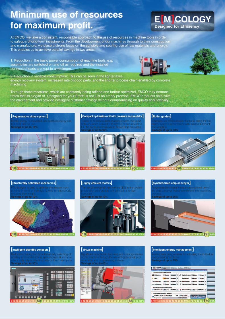
Direct CAD data import‑ AutoCAD (DWG)‑ Parasolid®‑ Solid Edge®‑ Solid Works®‑ ACIS® (SAT)‑ Optional interfaces: CATIA®,
Pro/ENGINEER®, STEP, STL,...
‑ 2‑22 axis turning‑ 2‑5 axis milling‑ Multi‑tasking of turning and milling‑ 3D machine space simulation‑ Certified post‑processors
The Esprit CAM system offers high flexibility and process security, a comprehensive selection of machining cycles, maximum tool control, and cross‑machine technology for your entire production facility.
[CAD]
[CAM]
[CAD]

‑ 1:1 simulation with collision detection‑ Direct connection to CAM ESPRIT‑ Process optimization‑ Reverse simulation of existing NC codes‑ Reduction in scrap rates‑ Training on the virtual machine‑ Simulation of loading systems
(e.g. EMCO gantry loader)
‑ Reduction in set‑up costs‑ Reduction in downtimes‑ Reduction in repair costs
OPTIMUM MACHINE UTILIzATION
A 1:1 mapping of the real machine for defining and testing processes, optimizing machining sequences, and training new operators.
The Virtual Machine
[Production]
[CPS]
[Process chain]
[CAD] [CAM] [CPS] [Production]

[Hydraulic systems]
Compact dimensions, quiet operation, and high energy efficiency - just some of the advantages of the hydraulic assemblies used by EMCO. Monitored pressure switches prevent the need for time-consuming manual pressure adjustments.
www.hawe.de
[Ball screws and roller guides]
Highly precise and generously dimen-sioned guide rails and ball screws with optimal pretensioning form the basis for the machining of precision parts.
www.boschrexroth.com
[Coolant pumps]
Low-maintenance immersion pumps for pressures of up to 25 bar and flow rates of up to 1500 l/min provide op-timum conditions for machining and enable reliable chip transportation.
www.grundfos.at
[Headstocks]
The design and manufacture of headstocks are two of EMCO‘s core competencies. During engineering, the focus is on precision, robustness, high rigidity, precise rotational cha-racteristics, and a long service life.
www.emco-magdeburg.de
[Tool turret]
Rapid-indexing turrets with adjustable swivel speeds and milling drives re-present the current state of the art. The backlash-free milling drive is not only ideal for milling and drilling, but also for rigid tapping, hobbing, and polygonal turning.
www.sauter-feinmechanik.com
[Tool holder]
Innovative, fully developed tool hol-der systems form the basis for cost-effective machining. High changeover accuracy and stability result in short setup and cycle times.
www.wto.de
[Clamping cylinder / chuck]
Hydraulically activated clamping cylinders and chucks guarantee the precise, safe clamping of work pieces. Programmable sensors are used for stroke monitoring. There is no need for time-consuming adjustments of contactless limit switches.
www.roehm.biz
[Chip conveyor]
Slat band conveyors allow for flexible implementation and the safe removal of chips. A monitored overload clutch prevents damage from improper use.
www.knollmb.de
[Machine bases and slides]
www.emco-magdeburg.de
When matching components, we place great value on high stability, good damping characteristics, and a thermoneutral design. We achieve high stability through a shorter force flow, thermal stability through symmetry, and dampening through the materials and interfaces selected.
Quality components
[Coolant pumps]
www.grundfos.at
[Tool holder]
www.wto.de
E[M]COLOGyDesigned for Efficiency
5 10 15 20 25 30 35 40 45 50 55 60 65 70 75 80 85 90 95 100%50
5 10 15 20 25 30 35 40 45 50 55 60 65 70 75 80 85 90 95 100%95
5 10 15 20 25 30 35 40 45 50 55 60 65 70 75 80 85 90 95 100%70
5 10 15 20 25 30 35 40 45 50 55 60 65 70 75 80 85 90 95 100%90
5 10 15 20 25 30 35 40 45 50 55 60 65 70 75 80 85 90 95 100%10
5 10 15 20 25 30 35 40 45 50 55 60 65 70 75 80 85 90 95 100%85
5 10 15 20 25 30 35 40 45 50 55 60 65 70 75 80 85 90 95 100%10
5 10 15 20 25 30 35 40 45 50 55 60 65 70 75 80 85 90 95 100%10
5 10 15 20 25 30 35 40 45 50 55 60 65 70 75 80 85 90 95 100%50
Minimum use of resources for maximum profit.At EMCO, we take a consistent, responsible approach to the use of resources in machine tools in order to safeguard long-term investments. From the development of our machines through to their construction and manufacture, we place a strong focus on the sensible and sparing use of raw materials and energy. This enables us to achieve parallel savings in two areas:
1. Reduction in the basic power consumption of machine tools, e.g. assemblies are switched on and off as required and the installedconnected loads are kept to a minimum.
2. Reduction in variable consumption: This can be seen in the lighter axes, energy recovery system, increased rate of good parts, and the shorter process chain enabled by complete machining.
Through these measures, which are constantly being refined and further optimized, EMCO truly demons-trates that its slogan of „Designed for your Profit“ is not just an empty promise: EMCO products help save the environment and provide intelligent customer savings without compromising on quality and flexibility.
[Compact hydraulics unit with pressure accumulator]
[Highly efficient motors]
[Virtual machine]
[Roller guides]
[Synchronized chip conveyor]
[Intelligent energy management]
[Regenerative drive system]
[Structurally optimized mechanics]
[Intelligent standby concepts]
Thanks to its accumulator charging system, the pump only runs when required. If the pressure accumulator is full, the pump switches over to closed loop circulation. Savings of up to 90%
The use of energy-efficient motors (IE2) in the coolant preparation area guarantee highly cost-effective operation. Savings of up to 10%
Significant reduction in the setup and running-in times on the machine through the use of highly developed simulation and programming software. Savings of up to 85%
Extremely low friction losses thanks to rolling friction. Highly dynamic performance with minimal lubricant consumption. Savings of up to 50%
Programmable interval times enable optimal use of the chip conveyor independently of of the machining process. Savings of up to 95%
Intuitive data entry screens for activating the individual energy-saving functions.Savings of up to 70%
Kinetic energy is converted into electrical energy and fed back into the grid. Savings of up to 10%
FEM analysis is used to optimize the relevant com-ponents in terms of their rigidity while simultaneously reducing their weight.Savings of up to 10%
Reduced consumption by automatically switching off ancillary units and machine space/screen illumination after a defined period of inactivity on the control panel. Savings of up to 50%

EMCO GmbH Salzburger Str. 80 . 5400 Hallein‑Taxach . AustriaTelefon +43 6245 891‑0 . Fax +43 6245 86965 . [email protected]
www.emco-world.com
EN
445
1 . 0
3/16
. Te
chni
cal m
odifi
catio
ns re
serv
ed. E
rror
s an
d om
issi
ons
exce
pted
.
[Technical data]
HyPERTURN 65 PowermillWork areaSwing over bed 500 mmDistance between spindle noses 1300 mmMaximum turning diameter 500 mmMax. part length 1040 mmMax. bar-stock diameter 65 (76/95) mmTravel Traverse path X1 / X2 405 / 210 mmTraverse path Z1 / Z2 1050 / 1050 mmTraverse path Y1 / Y2 220 / 100 mmTraverse path counter spindle Z3 1050 mmMain spindle Speed range (infinitely variable) 0 – 5000 (3500/4000) rpmMaximum torque 250 (360) NmSpindle nose DIN 55026 A2-6 (A2-8)Spindle bearing (inside diameter) 105 (130/140) mmSpindle bore (excluding draw-back rod) Ø 73 (86/106) mmCounter spindle Speed range (infinitely variable) 0 – 5000 rpmMaximum torque 250 NmSpindle nose DIN 55026 A2-6Spindle bearing (inside diameter) Ø 105 mmC‑axesResolution 0,001°Rapid traverse 1000 rpmDrive powerMain spindle (AC integrated-spindle motor) 29 (37) kWCounter spindle (AC integrated-spindle motor) 29 kWMilling spindle ‑ PowermillSpeed range 0 – 12000 rpmMaximum torque 79 NmMaximum Drive power 29 kWType of tool shank HSK-T63B‑axisTravel range 220°Holding torque of clamp 4000 NmInterpolating drive torque 332 NmTool magazine Tool storage capacity 20 / 40 / 80 mmMax. tool diameter Ø 80 (Ø 120) mm Max. tool length 250 mmMax. tool weight 5 kg
Tool turret Number of tool stations 12VDI shaft (DIN 69880) 30 (40) mmTool cross-section for square-shank tools 20 x 20 (25 x 25) mmShank diameter for boring bars 32 (40) mmTool indexing time 0,7 sec.Driven tools Spped range 0 – 5000 (4500) rpmTorque 25 NmDrive power 6,7 kWTool turret with BMT‑interface and direct driveNumber of tool positions 12Precision interface BMT-55PTool cross-section for square-shank tools 20 x 20 (25 x 25) mmShank diameter for boring bars 40 mmTool indexing time 0,5 secSpeed range of driven tools 0 – 12000 rpmTorque of driven tools 30 NmDrive power of driven tools 10 kWFeed drives Rapid speed X1 / X2 30 m/minRapid speed Z1 / Z2 / Z3 30 m/minRapid speed Y1 / Y2 12 m/minFeed force X1 / X2 5000 NFeed force Z1 / Z2 8000 NFeed force Y1 / Y2 7000 NCoolant system Tank capacity 450 lPump capacity 2 x 3,7 kWPower consumption Connected load 50 kVACompressed air 6 barDimensions Height of center above floor 1316 mmOverall height 2490 mmRequired space L x D (without chip conveyor) 5300 x 3450 mmTotal weight 12250 kgSafety devices CE compliant
ZERTIFIZIERT
TÜV AUSTRIA CERT GMBH
EN ISO 9001
ZERTIFIKAT NR. 20 100 20419


