Copyright 2002, OTIS GmbH & Co. OHG Berlin
OTISCentral & East Europe
Area
PRODUCTADMINISTRATION
FIELD COMPONENT MANUAL
Software Data
MCS - RCB IIInstallation Parameters - MCS 311 / 321 / 411/ 413
Part: 4 - AA3No.: GCA21270A VIIIaVintage: 01 / 10Page: 1 / 34D1: 25-Oct-2002
Date: 14-Oct-2002SCN: GAE30075JAA
MCS - RCB II
Software - Installation Parameters MCS 311 / 321 / 411 / 413
Copyright 2002, OTIS GmbH & Co. OHG BerlinNo part of this document may be copied or reproduced in any form or by any means without the prior written
consent of OTIS GmbH & Co, OHG.
Authorization Date D1: 25-Oct-2002
Running on PCB: GCA 21270 A2 or higher
Software Version: GAE30075JAA
Document Revision :
Date SCN Author Comment24-Jan-1994 GAC 30075 BAA Botta Original Document30-Jun-1995 GAE 30075 EAA Szekeres Major revision of document20-Jan-1996 GAE 30075 FAA Hildebrand Revision, Separation of MCS 311 /411
and MCS 32125-Sep-1996 GAE 30075 GAA Szekeres update for GAA release31-Jul-1997 GAE 30075 HAA Szekeres update for HAA release16-Feb-1998 GAE 30075 HAB Dridi. Update for HAB release25-May-2000 GAE 30075 HAC Seelmann Enable ACG Type 2 added14-Oct-2002 GAE 30075 JAA Seelmann Revision for release
Copyright 2002, OTIS GmbH & Co. OHG Berlin
OTISCentral & East Europe
Area
PRODUCTADMINISTRATION
FIELD COMPONENT MANUAL
Software Data
MCS - RCB IIInstallation Parameters - MCS 311 / 321 / 411/ 413
Part: 4 - AA3No.: GCA21270A VIIIaVintage: 01 / 10Page: 2 / 34D1: 25-Oct-2002
Date: 14-Oct-2002SCN: GAE30075JAA
Table of Contents
1 SYSTEM < M - 1 - 3 - 1 - 1 >.................................................................. 3
2 DOOR < M - 1 - 3 - 1 - 2 >....................................................................... 7
3 DRIVE/FIELD < M - 1 - 3 - 1 - 3 > .......................................................... 9
4 GROUP < M - 1 - 3 - 1 - 4 > ................................................................. 10
5 DISPATCHING < M - 1 - 3 - 1 - 5 >....................................................... 18
6 EMERGENCY < M - 1 - 3 - 1 - 6 > ....................................................... 21
7 SECURITY < M - 1 - 3 - 1 - 7 > ............................................................. 28
8 SIGNAL DEV < M - 1 - 3 - 1 - 8 >......................................................... 31
9 DEBUG/TEST < M - 1 - 3 - 1 - 9 > ....................................................... 34
Note:Shaded Variables are depending of the Controller Type or some
other parameters.These are only displayed if the related condition is met. !!!!
Copyright 2002, OTIS GmbH & Co. OHG Berlin
OTISCentral & East Europe
Area
PRODUCTADMINISTRATION
FIELD COMPONENT MANUAL
Software Data
MCS - RCB IIInstallation Parameters - MCS 311 / 321 / 411/ 413
Part: 4 - AA3No.: GCA21270A VIIIaVintage: 01 / 10Page: 3 / 34D1: 25-Oct-2002
Date: 14-Oct-2002SCN: GAE30075JAA
1 SYSTEM < M - 1 - 3 - 1 - 1 >
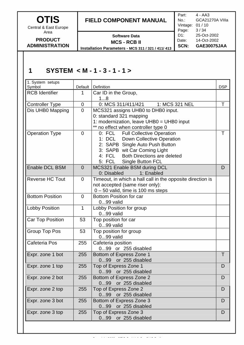
1. System setupsSymbol Default Definition DSPRCB Identifier 1 Car ID in the Group,
1...8Controller Type 0 0: MCS 311/411/421 1: MCS 321 NEL TDis UHB0 Mapping 0 MCS321 assigns UHB0 to DHB0 input.
0: standard 321 mapping1: modernization, leave UHB0 = UHB0 input** no effect when controller type 0
Operation Type 0 0: FCL Full Collective Operation1: DCL Down Collective Operation2: SAPB Single Auto Push Button3: SAPB wit Car Coming Light4: FCL Both Directions are deleted5: FCL Single Button FCL
T
Enable DCL BSM 0 MCS321 Enable BSM during DCL0: Disabled 1: Enabled
D
Reverse HC Tout 0 Timeout, in which a hall call in the opposite direction isnot accepted (same riser only): 0 – 50 valid, time is 100 ms steps
Bottom Position 0 Bottom Position for car0...99 valid
Lobby Position 1 Lobby Position for group0...99 valid
Car Top Position 53 Top position for car0...99 valid
Group Top Pos 53 Top position for group0...99 valid
Cafeteria Pos 255 Cafeteria position0...99 or 255 disabled
Expr. zone 1 bot 255 Bottom of Express Zone 10...99 or 255 disabled
T
Expr. zone 1 top 255 Top of Express Zone 10...99 or 255 disabled
D
Expr. zone 2 bot 255 Bottom of Express Zone 20...99 or 255 disabled
D
Expr. zone 2 top 255 Top of Express Zone 20...99 or 255 disabled
D
Expr. zone 3 bot 255 Bottom of Express Zone 30...99 or 255 disabled
D
Expr. zone 3 top 255 Top of Express Zone 30...99 or 255 disabled
D
Copyright 2002, OTIS GmbH & Co. OHG Berlin
OTISCentral & East Europe
Area
PRODUCTADMINISTRATION
FIELD COMPONENT MANUAL
Software Data
MCS - RCB IIInstallation Parameters - MCS 311 / 321 / 411/ 413
Part: 4 - AA3No.: GCA21270A VIIIaVintage: 01 / 10Page: 4 / 34D1: 25-Oct-2002
Date: 14-Oct-2002SCN: GAE30075JAA
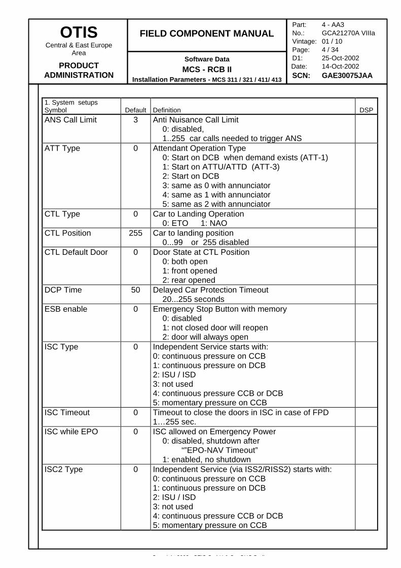
1. System setupsSymbol Default Definition DSPANS Call Limit 3 Anti Nuisance Call Limit
0: disabled,1..255 car calls needed to trigger ANS
ATT Type 0 Attendant Operation Type0: Start on DCB when demand exists (ATT-1)1: Start on ATTU/ATTD (ATT-3)2: Start on DCB3: same as 0 with annunciator4: same as 1 with annunciator5: same as 2 with annunciator
CTL Type 0 Car to Landing Operation0: ETO 1: NAO
CTL Position 255 Car to landing position0...99 or 255 disabled
CTL Default Door 0 Door State at CTL Position0: both open1: front opened2: rear opened
DCP Time 50 Delayed Car Protection Timeout20...255 seconds
ESB enable 0 Emergency Stop Button with memory0: disabled1: not closed door will reopen2: door will always open
ISC Type 0 Independent Service starts with:0: continuous pressure on CCB1: continuous pressure on DCB2: ISU / ISD3: not used4: continuous pressure CCB or DCB5: momentary pressure on CCB
ISC Timeout 0 Timeout to close the doors in ISC in case of FPD1…255 sec.
ISC while EPO 0 ISC allowed on Emergency Power0: disabled, shutdown after
“”EPO-NAV Timeout”1: enabled, no shutdown
ISC2 Type 0 Independent Service (via ISS2/RISS2) starts with:0: continuous pressure on CCB1: continuous pressure on DCB2: ISU / ISD3: not used4: continuous pressure CCB or DCB5: momentary pressure on CCB

Copyright 2002, OTIS GmbH & Co. OHG Berlin
OTISCentral & East Europe
Area
PRODUCTADMINISTRATION
FIELD COMPONENT MANUAL
Software Data
MCS - RCB IIInstallation Parameters - MCS 311 / 321 / 411/ 413
Part: 4 - AA3No.: GCA21270A VIIIaVintage: 01 / 10Page: 5 / 34D1: 25-Oct-2002
Date: 14-Oct-2002SCN: GAE30075JAA
1. System setupsSymbol Default Definition DSPLight Relay Time 20 Light Relay Time
1...255 secondsPerf Monitor Int 10 CPU Monitoring Interval (For Engineering use)
0...255 secondsCar Calls Behind 0 Car Calls behind a moving car´s position
0: Car Calls are enabled1: Car Calls are disabled
SaveCalls in OLD 0 Save Car calls if car goes in overload mode0: calls are deleted1: calls are saved
OCSS-MCSS ICD 0 For LMCSS (only 2 byte messages)0: GBA30085 AAA (V3.3)1: GBA30085 BAA (V4.0)2: GBA30085 CAA (V4.1)3: GBA30085 EAA or higher (V4.2)
For MCSS (2 byte and 4 byte messages*)0: AAA 30045 AAF or higher (2 bytes) MCSS does not support loadweighing From OCSS or alternate door profiles
100: AAA30045AAF (4 bytes)101: AAA30045AAH (4 bytes)102: AAA30045AAI or higher (4 bytes)* 4 bytes only used for double deck, fuzzy logic, orspecial Japanese features
Note: MCSS with alternate door profiles requiresA1130045AAKE or higher
Safety Note: Units with EFO, EFS, EPO, EQO has tobe equipped with- GBA30085HAA01 or higher- AAA30045AAI or higher
OCSS-EMS ICD 0 When EMS is configured for version 3.3, 4.0, 4.1 ICDlevel it needs load weight and actual position in statusmessages. When the ICD setups of OCSS and EMSdo not match the cars jump on the EMS display andload weight is not shown correctly.
0: EMS is at ICD Level 3.3, 4.0, 4.11: EMS is configured for 4.2
Load weighing 0 Load weighing inputs connected to0: DISS (E411)1: OCSS (MCS311/SPEC90)
Copyright 2002, OTIS GmbH & Co. OHG Berlin
OTISCentral & East Europe
Area
PRODUCTADMINISTRATION
FIELD COMPONENT MANUAL
Software Data
MCS - RCB IIInstallation Parameters - MCS 311 / 321 / 411/ 413
Part: 4 - AA3No.: GCA21270A VIIIaVintage: 01 / 10Page: 6 / 34D1: 25-Oct-2002
Date: 14-Oct-2002SCN: GAE30075JAA
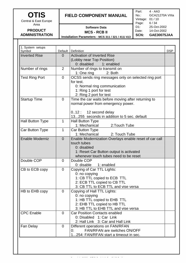
1. System setupsSymbol Default Definition DSPInverted Rise 0 Activation of Inverted Rise
(Lobby near Top Position)0: disabled 1: enabled
Number of rings 2 Number of rings to transmit on1: One ring 2: Both
Test Ring Port 0 OCSS sends ring messages only on selected ring portfor test.
0: Normal ring communication1: Ring 1 port for test2: Ring 2 port for test
Startup Time 0 Time the car waits before moving after returning tonormal power from emergency power.
0..12 : 12 second delay13...255 seconds in addition to 5 sec. default
Hall Button Type 1 Hall Button Type1: Mechanical 2:Touch Tube
Car Button Type 1 Car Button Type1: Mechanical 2: Touch Tube
Enable Moderniz 0 Enable Modernization Overlays enable reset of car calltouch tubes
0: disabled1: Reset Car Button output is activated whenever touch tubes need to be reset
Double COP 0 Double COP0: disable 1: enabled
CB to ECB copy 0 Copying of Car TTL Lights:0: no copying1: CB TTL copied to ECB TTL2: ECB TTL copied to CB TTL3: CB TTL to ECB TTL and vise versa
HB to EHB copy 0 Copying of Hall TTL Lights:0: no copying1: HB TTL copied to EHB TTL2: EHB TTL copied to HB TTL3: HB TTL to EHB TTL and vise versa
CPC Enable 0 Car Position Contacts enabled0: Disabled 1: Car Link2: Hall Link 3: Car and Hall Link
Fan Delay 0 Different operations on FAN/RFAN0: FAN/RFAN are switches ON/OFF1...254: FAN/RFAN start a timeout in sec.
Copyright 2002, OTIS GmbH & Co. OHG Berlin
OTISCentral & East Europe
Area
PRODUCTADMINISTRATION
FIELD COMPONENT MANUAL
Software Data
MCS - RCB IIInstallation Parameters - MCS 311 / 321 / 411/ 413
Part: 4 - AA3No.: GCA21270A VIIIaVintage: 01 / 10Page: 7 / 34D1: 25-Oct-2002
Date: 14-Oct-2002SCN: GAE30075JAA
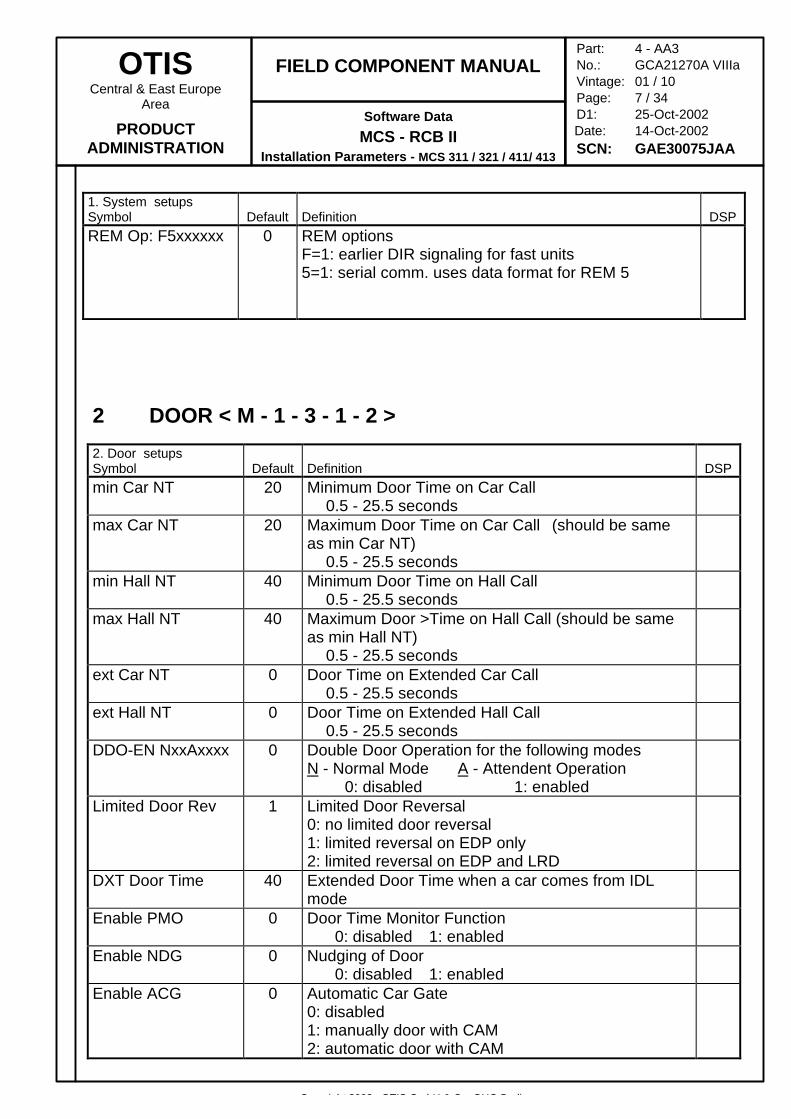
1. System setupsSymbol Default Definition DSPREM Op: F5xxxxxx 0 REM options
F=1: earlier DIR signaling for fast units5=1: serial comm. uses data format for REM 5
2 DOOR < M - 1 - 3 - 1 - 2 >
2. Door setupsSymbol Default Definition DSPmin Car NT 20 Minimum Door Time on Car Call
0.5 - 25.5 secondsmax Car NT 20 Maximum Door Time on Car Call (should be same
as min Car NT)0.5 - 25.5 seconds
min Hall NT 40 Minimum Door Time on Hall Call0.5 - 25.5 seconds
max Hall NT 40 Maximum Door >Time on Hall Call (should be sameas min Hall NT)
0.5 - 25.5 secondsext Car NT 0 Door Time on Extended Car Call
0.5 - 25.5 secondsext Hall NT 0 Door Time on Extended Hall Call
0.5 - 25.5 secondsDDO-EN NxxAxxxx 0 Double Door Operation for the following modes
N - Normal Mode A - Attendent Operation0: disabled 1: enabled
Limited Door Rev 1 Limited Door Reversal0: no limited door reversal1: limited reversal on EDP only2: limited reversal on EDP and LRD
DXT Door Time 40 Extended Door Time when a car comes from IDLmode
Enable PMO 0 Door Time Monitor Function 0: disabled 1: enabled
Enable NDG 0 Nudging of Door 0: disabled 1: enabled
Enable ACG 0 Automatic Car Gate0: disabled1: manually door with CAM2: automatic door with CAM
Copyright 2002, OTIS GmbH & Co. OHG Berlin
OTISCentral & East Europe
Area
PRODUCTADMINISTRATION
FIELD COMPONENT MANUAL
Software Data
MCS - RCB IIInstallation Parameters - MCS 311 / 321 / 411/ 413
Part: 4 - AA3No.: GCA21270A VIIIaVintage: 01 / 10Page: 8 / 34D1: 25-Oct-2002
Date: 14-Oct-2002SCN: GAE30075JAA
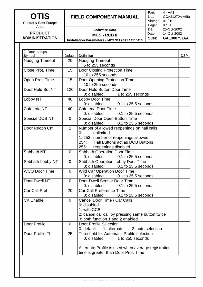
2. Door setupsSymbol Default Definition DSPNudging Timeout 20 Nudging Timeout
5 to 255 secondsClose Prot. Time 15 Door Closing Protection Time
10 to 255 secondsOpen Prot. Time 15 Door Opening Protection Time
10 to 255 secondsDoor Hold But NT 120 Door Hold Button Door Time
0: disabled 1 to 255 secondsLobby NT 40 Lobby Door Time
0: disabled 0.1 to 25.5 secondsCafeteria NT 40 Cafeteria Door Time
0: disabled 0.1 to 25.5 secondsSpecial DOB NT 0 Special Door Open Button Time
0: disabled 0.1 to 25.5 secondsDoor Reopn Cnt 2 Number of allowed reopenings on hall calls
0: unlimited1..253: number of reopenings allowed254: Hall Buttons act as DOB Buttons255: reopenings disabled
Sabbath NT 0 Sabbath Operation Door Time0: disabled 0.1 to 25.5 seconds
Sabbath Lobby NT 0 Sabbath Operation Lobby Door Time0: disabled 0.1 to 25.5 seconds
WCO Door Time 0 Wild Car Operation Door Time0: disabled 0.1 to 25.5 seconds
Door Dwell NT 0 Door Dwell Sensor Door Time0: disabled 0.1 to 25.5 seconds
Car Call Pref 20 Car Call Preference Time0: disabled 0.1 to 25.5 seconds
CK Enable 0 Cancel Door Time / Car Calls0: disabled1: with CCB2: cancel car call by pressing same button twice3: both function 1 and 2 enabled
Door Profile 0 Door Profile Selection0: default 1: alternate 2: auto selection
Door Profile Thr 25 Threshold for Automatic Profile selection0: disabled 1 to 255 seconds
Alternate Profile is used when average registrationtime is greater than Door Prof. Time
Copyright 2002, OTIS GmbH & Co. OHG Berlin
OTISCentral & East Europe
Area
PRODUCTADMINISTRATION
FIELD COMPONENT MANUAL
Software Data
MCS - RCB IIInstallation Parameters - MCS 311 / 321 / 411/ 413
Part: 4 - AA3No.: GCA21270A VIIIaVintage: 01 / 10Page: 9 / 34D1: 25-Oct-2002
Date: 14-Oct-2002SCN: GAE30075JAA
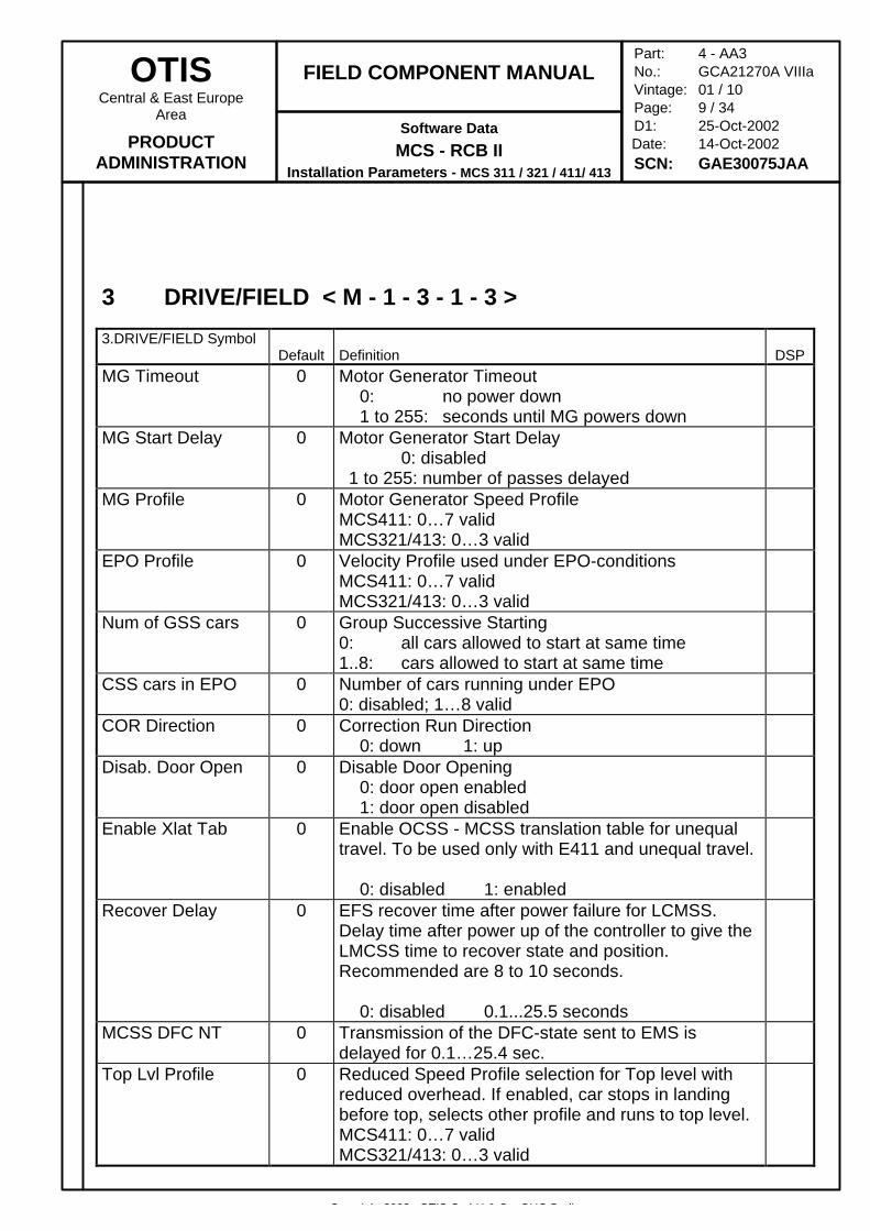
3 DRIVE/FIELD < M - 1 - 3 - 1 - 3 >
3.DRIVE/FIELD SymbolDefault Definition DSP
MG Timeout 0 Motor Generator Timeout0: no power down1 to 255: seconds until MG powers down
MG Start Delay 0 Motor Generator Start Delay0: disabled
1 to 255: number of passes delayedMG Profile 0 Motor Generator Speed Profile
MCS411: 0…7 validMCS321/413: 0…3 valid
EPO Profile 0 Velocity Profile used under EPO-conditionsMCS411: 0…7 validMCS321/413: 0…3 valid
Num of GSS cars 0 Group Successive Starting0: all cars allowed to start at same time1..8: cars allowed to start at same time
CSS cars in EPO 0 Number of cars running under EPO0: disabled; 1…8 valid
COR Direction 0 Correction Run Direction0: down 1: up
Disab. Door Open 0 Disable Door Opening0: door open enabled1: door open disabled
Enable Xlat Tab 0 Enable OCSS - MCSS translation table for unequaltravel. To be used only with E411 and unequal travel.
0: disabled 1: enabledRecover Delay 0 EFS recover time after power failure for LCMSS.
Delay time after power up of the controller to give theLMCSS time to recover state and position.Recommended are 8 to 10 seconds.
0: disabled 0.1...25.5 secondsMCSS DFC NT 0 Transmission of the DFC-state sent to EMS is
delayed for 0.1…25.4 sec.Top Lvl Profile 0 Reduced Speed Profile selection for Top level with
reduced overhead. If enabled, car stops in landingbefore top, selects other profile and runs to top level.MCS411: 0…7 validMCS321/413: 0…3 valid
Copyright 2002, OTIS GmbH & Co. OHG Berlin
OTISCentral & East Europe
Area
PRODUCTADMINISTRATION
FIELD COMPONENT MANUAL
Software Data
MCS - RCB IIInstallation Parameters - MCS 311 / 321 / 411/ 413
Part: 4 - AA3No.: GCA21270A VIIIaVintage: 01 / 10Page: 10 / 34D1: 25-Oct-2002
Date: 14-Oct-2002SCN: GAE30075JAA
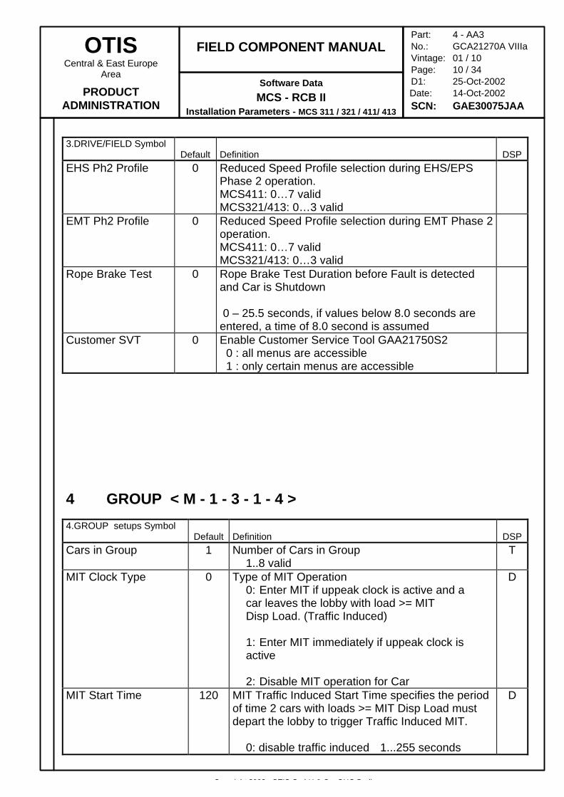
3.DRIVE/FIELD SymbolDefault Definition DSP
EHS Ph2 Profile 0 Reduced Speed Profile selection during EHS/EPSPhase 2 operation.MCS411: 0…7 validMCS321/413: 0…3 valid
EMT Ph2 Profile 0 Reduced Speed Profile selection during EMT Phase 2operation.MCS411: 0…7 validMCS321/413: 0…3 valid
Rope Brake Test 0 Rope Brake Test Duration before Fault is detectedand Car is Shutdown
0 – 25.5 seconds, if values below 8.0 seconds areentered, a time of 8.0 second is assumed
Customer SVT 0 Enable Customer Service Tool GAA21750S2 0 : all menus are accessible 1 : only certain menus are accessible
4 GROUP < M - 1 - 3 - 1 - 4 >
4.GROUP setups SymbolDefault Definition DSP
Cars in Group 1 Number of Cars in Group1..8 valid
T
MIT Clock Type 0 Type of MIT Operation0: Enter MIT if uppeak clock is active and a car leaves the lobby with load >= MIT Disp Load. (Traffic Induced)
1: Enter MIT immediately if uppeak clock is active
2: Disable MIT operation for Car
D
MIT Start Time 120 MIT Traffic Induced Start Time specifies the periodof time 2 cars with loads >= MIT Disp Load mustdepart the lobby to trigger Traffic Induced MIT.
0: disable traffic induced 1...255 seconds
D
Copyright 2002, OTIS GmbH & Co. OHG Berlin
OTISCentral & East Europe
Area
PRODUCTADMINISTRATION
FIELD COMPONENT MANUAL
Software Data
MCS - RCB IIInstallation Parameters - MCS 311 / 321 / 411/ 413
Part: 4 - AA3No.: GCA21270A VIIIaVintage: 01 / 10Page: 11 / 34D1: 25-Oct-2002
Date: 14-Oct-2002SCN: GAE30075JAA
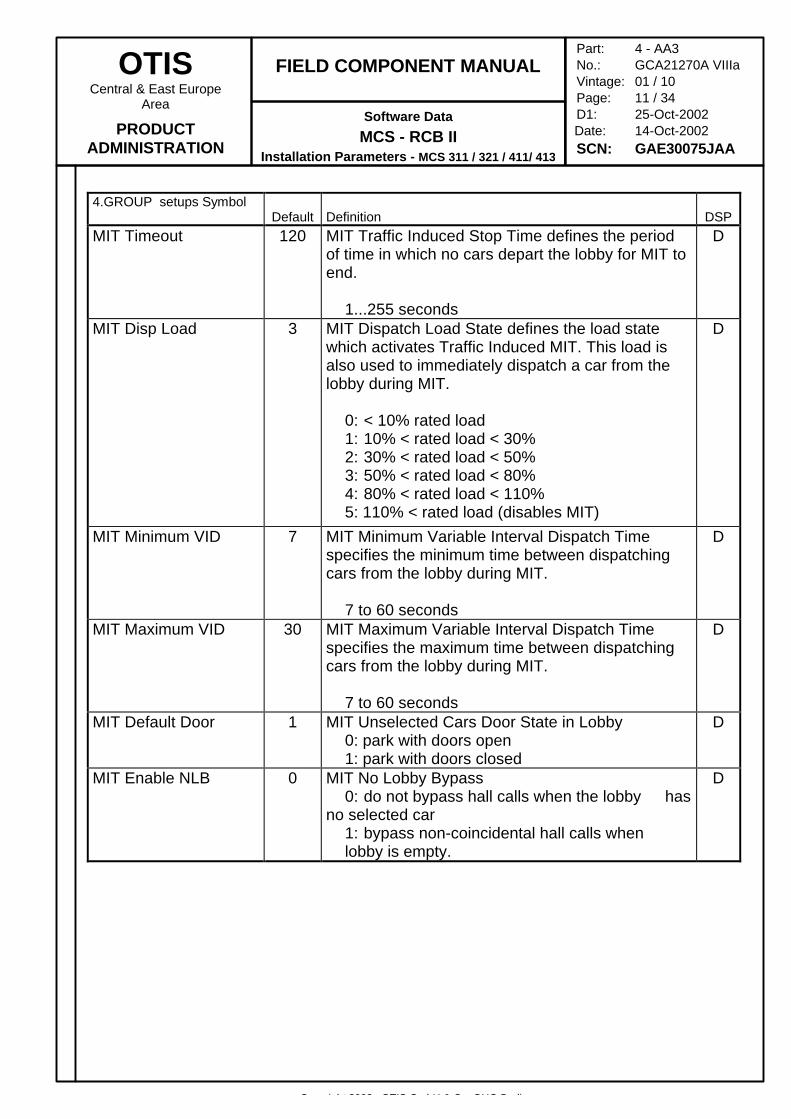
4.GROUP setups SymbolDefault Definition DSP
MIT Timeout 120 MIT Traffic Induced Stop Time defines the periodof time in which no cars depart the lobby for MIT toend.
1...255 seconds
D
MIT Disp Load 3 MIT Dispatch Load State defines the load statewhich activates Traffic Induced MIT. This load isalso used to immediately dispatch a car from thelobby during MIT.
0: < 10% rated load1: 10% < rated load < 30%2: 30% < rated load < 50%3: 50% < rated load < 80%4: 80% < rated load < 110%5: 110% < rated load (disables MIT)
D
MIT Minimum VID 7 MIT Minimum Variable Interval Dispatch Timespecifies the minimum time between dispatchingcars from the lobby during MIT.
7 to 60 seconds
D
MIT Maximum VID 30 MIT Maximum Variable Interval Dispatch Timespecifies the maximum time between dispatchingcars from the lobby during MIT.
7 to 60 seconds
D
MIT Default Door 1 MIT Unselected Cars Door State in Lobby0: park with doors open1: park with doors closed
D
MIT Enable NLB 0 MIT No Lobby Bypass0: do not bypass hall calls when the lobby has
no selected car1: bypass non-coincidental hall calls when lobby is empty.
D
Copyright 2002, OTIS GmbH & Co. OHG Berlin
OTISCentral & East Europe
Area
PRODUCTADMINISTRATION
FIELD COMPONENT MANUAL
Software Data
MCS - RCB IIInstallation Parameters - MCS 311 / 321 / 411/ 413
Part: 4 - AA3No.: GCA21270A VIIIaVintage: 01 / 10Page: 12 / 34D1: 25-Oct-2002
Date: 14-Oct-2002SCN: GAE30075JAA
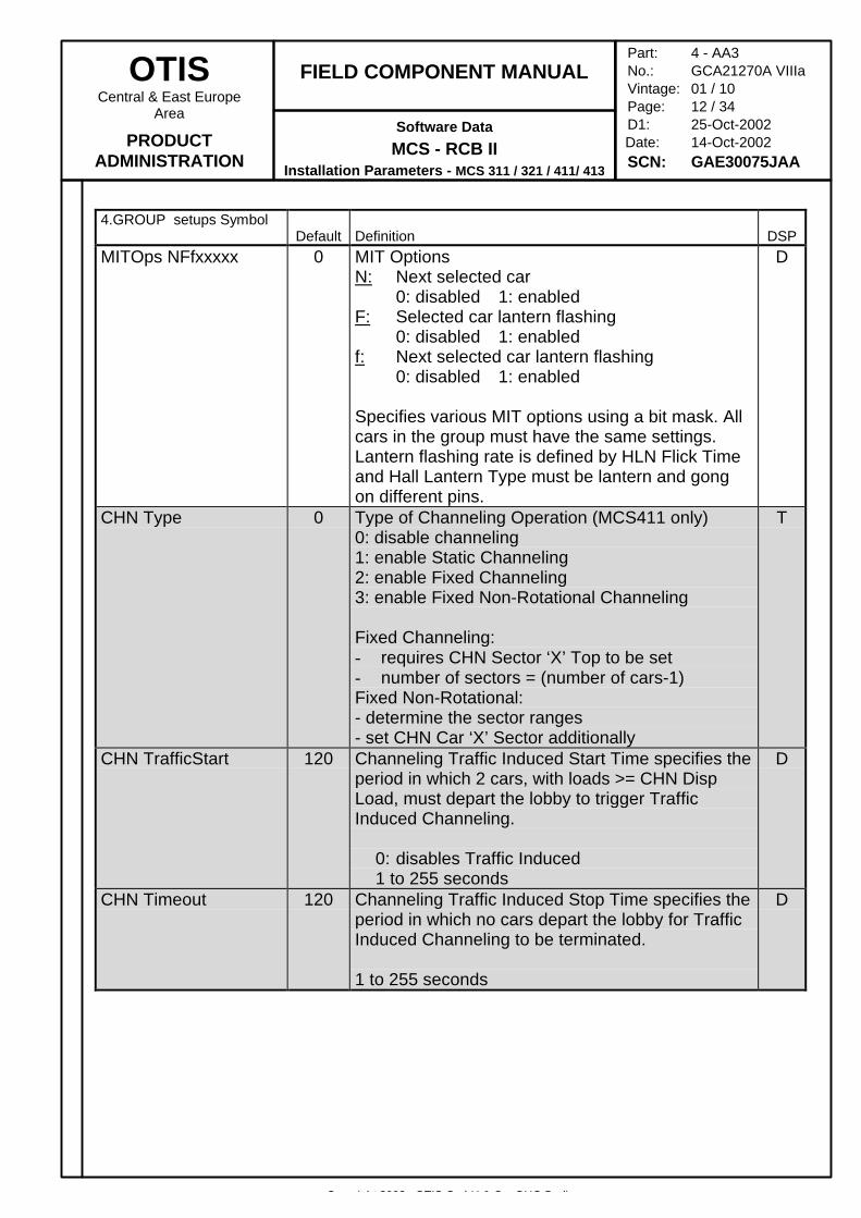
4.GROUP setups SymbolDefault Definition DSP
MITOps NFfxxxxx 0 MIT OptionsN: Next selected car
0: disabled 1: enabledF: Selected car lantern flashing
0: disabled 1: enabledf: Next selected car lantern flashing
0: disabled 1: enabled
Specifies various MIT options using a bit mask. Allcars in the group must have the same settings.Lantern flashing rate is defined by HLN Flick Timeand Hall Lantern Type must be lantern and gongon different pins.
D
CHN Type 0 Type of Channeling Operation (MCS411 only)0: disable channeling1: enable Static Channeling2: enable Fixed Channeling3: enable Fixed Non-Rotational Channeling
Fixed Channeling:- requires CHN Sector ‘X’ Top to be set- number of sectors = (number of cars-1)Fixed Non-Rotational:- determine the sector ranges- set CHN Car ‘X’ Sector additionally
T
CHN TrafficStart 120 Channeling Traffic Induced Start Time specifies theperiod in which 2 cars, with loads >= CHN DispLoad, must depart the lobby to trigger TrafficInduced Channeling.
0: disables Traffic Induced1 to 255 seconds
D
CHN Timeout 120 Channeling Traffic Induced Stop Time specifies theperiod in which no cars depart the lobby for TrafficInduced Channeling to be terminated.
1 to 255 seconds
D
Copyright 2002, OTIS GmbH & Co. OHG Berlin
OTISCentral & East Europe
Area
PRODUCTADMINISTRATION
FIELD COMPONENT MANUAL
Software Data
MCS - RCB IIInstallation Parameters - MCS 311 / 321 / 411/ 413
Part: 4 - AA3No.: GCA21270A VIIIaVintage: 01 / 10Page: 13 / 34D1: 25-Oct-2002
Date: 14-Oct-2002SCN: GAE30075JAA
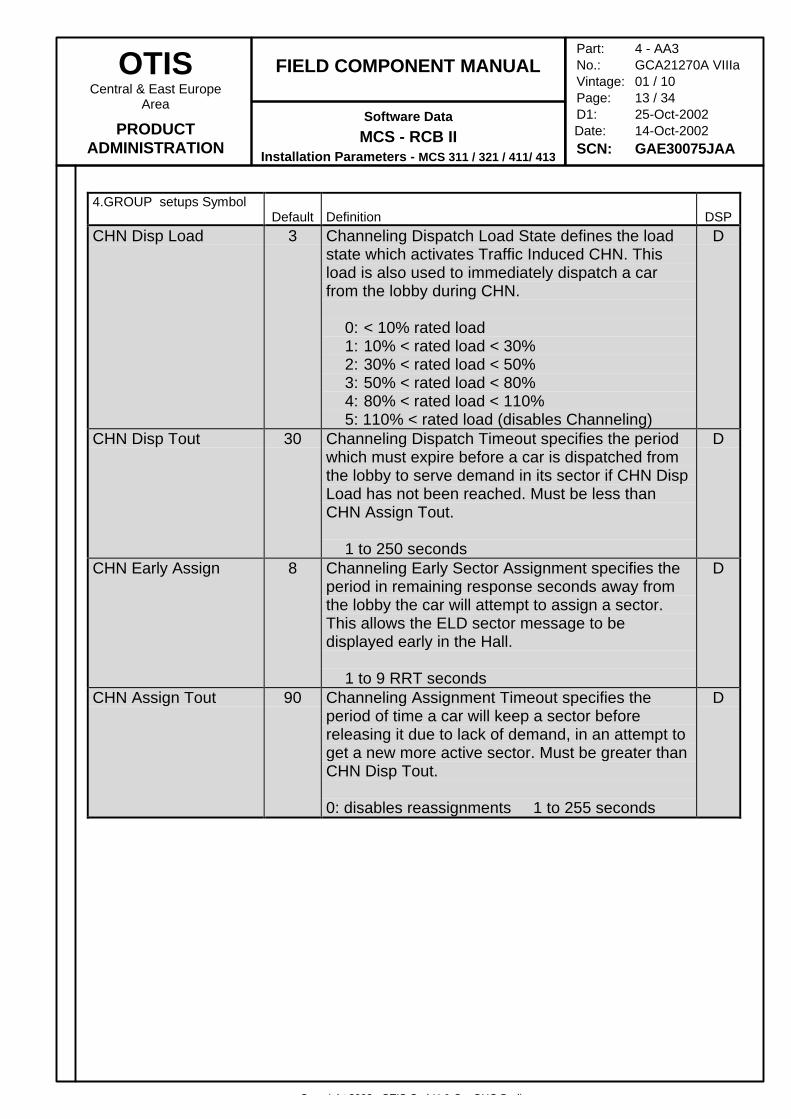
4.GROUP setups SymbolDefault Definition DSP
CHN Disp Load 3 Channeling Dispatch Load State defines the loadstate which activates Traffic Induced CHN. Thisload is also used to immediately dispatch a carfrom the lobby during CHN.
0: < 10% rated load1: 10% < rated load < 30%2: 30% < rated load < 50%3: 50% < rated load < 80%4: 80% < rated load < 110%5: 110% < rated load (disables Channeling)
D
CHN Disp Tout 30 Channeling Dispatch Timeout specifies the periodwhich must expire before a car is dispatched fromthe lobby to serve demand in its sector if CHN DispLoad has not been reached. Must be less thanCHN Assign Tout.
1 to 250 seconds
D
CHN Early Assign 8 Channeling Early Sector Assignment specifies theperiod in remaining response seconds away fromthe lobby the car will attempt to assign a sector.This allows the ELD sector message to bedisplayed early in the Hall.
1 to 9 RRT seconds
D
CHN Assign Tout 90 Channeling Assignment Timeout specifies theperiod of time a car will keep a sector beforereleasing it due to lack of demand, in an attempt toget a new more active sector. Must be greater thanCHN Disp Tout.
0: disables reassignments 1 to 255 seconds
D
Copyright 2002, OTIS GmbH & Co. OHG Berlin
OTISCentral & East Europe
Area
PRODUCTADMINISTRATION
FIELD COMPONENT MANUAL
Software Data
MCS - RCB IIInstallation Parameters - MCS 311 / 321 / 411/ 413
Part: 4 - AA3No.: GCA21270A VIIIaVintage: 01 / 10Page: 14 / 34D1: 25-Oct-2002
Date: 14-Oct-2002SCN: GAE30075JAA
4.GROUP setups SymbolDefault Definition DSP
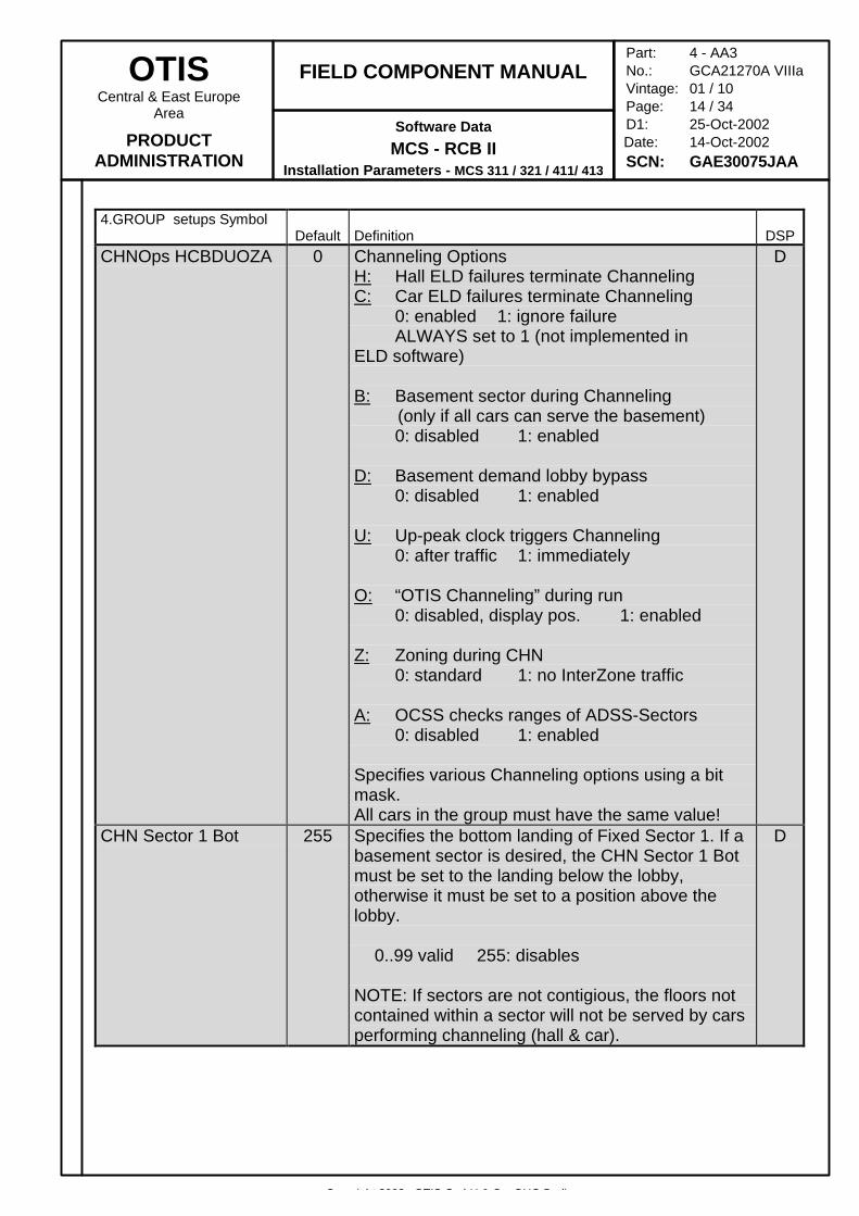
CHNOps HCBDUOZA 0 Channeling OptionsH: Hall ELD failures terminate ChannelingC: Car ELD failures terminate Channeling
0: enabled 1: ignore failureALWAYS set to 1 (not implemented in
ELD software)
B: Basement sector during Channeling (only if all cars can serve the basement)
0: disabled 1: enabled
D: Basement demand lobby bypass0: disabled 1: enabled
U: Up-peak clock triggers Channeling0: after traffic 1: immediately
O: “OTIS Channeling” during run0: disabled, display pos. 1: enabled
Z: Zoning during CHN0: standard 1: no InterZone traffic
A: OCSS checks ranges of ADSS-Sectors0: disabled 1: enabled
Specifies various Channeling options using a bitmask.All cars in the group must have the same value!
D
CHN Sector 1 Bot 255 Specifies the bottom landing of Fixed Sector 1. If abasement sector is desired, the CHN Sector 1 Botmust be set to the landing below the lobby,otherwise it must be set to a position above thelobby.
0..99 valid 255: disables
NOTE: If sectors are not contigious, the floors notcontained within a sector will not be served by carsperforming channeling (hall & car).
D
Copyright 2002, OTIS GmbH & Co. OHG Berlin
OTISCentral & East Europe
Area
PRODUCTADMINISTRATION
FIELD COMPONENT MANUAL
Software Data
MCS - RCB IIInstallation Parameters - MCS 311 / 321 / 411/ 413
Part: 4 - AA3No.: GCA21270A VIIIaVintage: 01 / 10Page: 15 / 34D1: 25-Oct-2002
Date: 14-Oct-2002SCN: GAE30075JAA
4.GROUP setups SymbolDefault Definition DSP
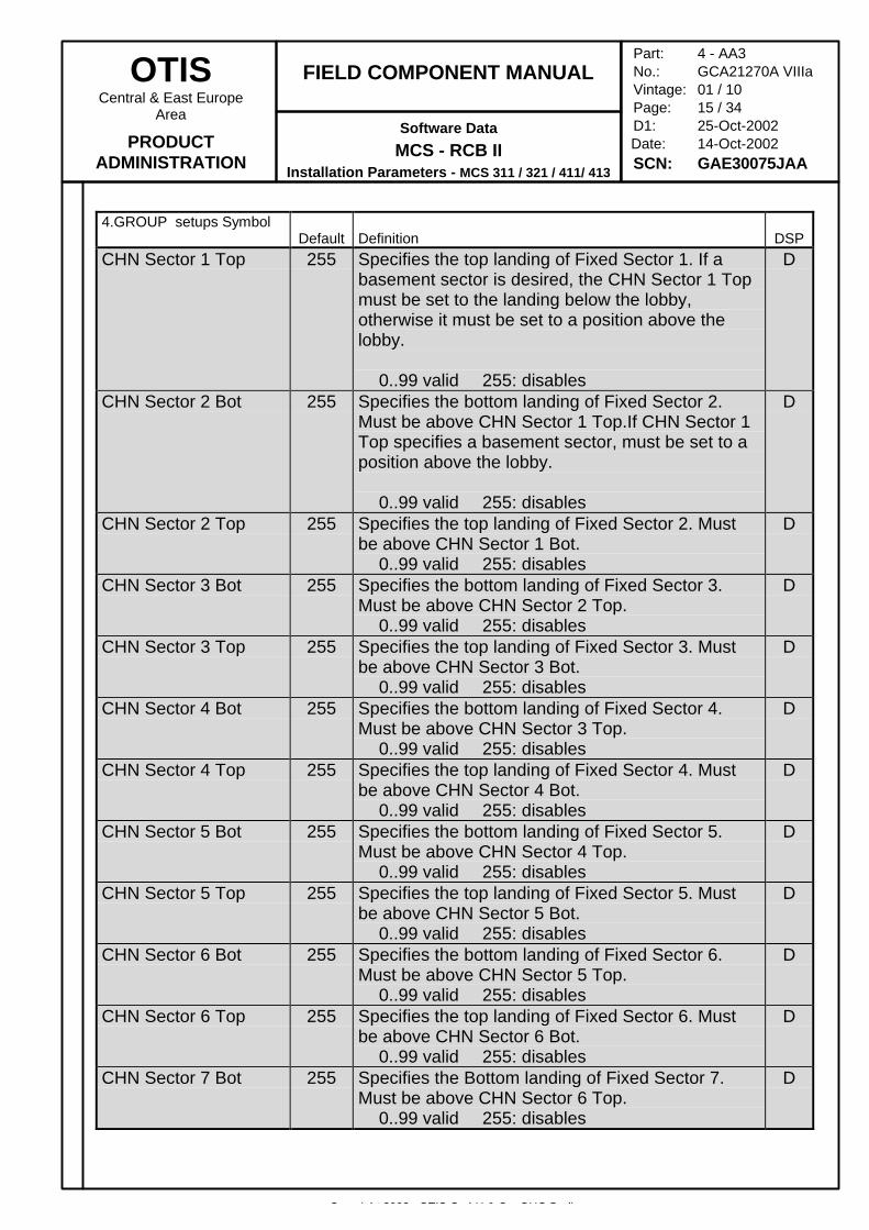
CHN Sector 1 Top 255 Specifies the top landing of Fixed Sector 1. If abasement sector is desired, the CHN Sector 1 Topmust be set to the landing below the lobby,otherwise it must be set to a position above thelobby.
0..99 valid 255: disables
D
CHN Sector 2 Bot 255 Specifies the bottom landing of Fixed Sector 2.Must be above CHN Sector 1 Top.If CHN Sector 1Top specifies a basement sector, must be set to aposition above the lobby.
0..99 valid 255: disables
D
CHN Sector 2 Top 255 Specifies the top landing of Fixed Sector 2. Mustbe above CHN Sector 1 Bot.
0..99 valid 255: disables
D
CHN Sector 3 Bot 255 Specifies the bottom landing of Fixed Sector 3.Must be above CHN Sector 2 Top.
0..99 valid 255: disables
D
CHN Sector 3 Top 255 Specifies the top landing of Fixed Sector 3. Mustbe above CHN Sector 3 Bot.
0..99 valid 255: disables
D
CHN Sector 4 Bot 255 Specifies the bottom landing of Fixed Sector 4.Must be above CHN Sector 3 Top.
0..99 valid 255: disables
D
CHN Sector 4 Top 255 Specifies the top landing of Fixed Sector 4. Mustbe above CHN Sector 4 Bot.
0..99 valid 255: disables
D
CHN Sector 5 Bot 255 Specifies the bottom landing of Fixed Sector 5.Must be above CHN Sector 4 Top.
0..99 valid 255: disables
D
CHN Sector 5 Top 255 Specifies the top landing of Fixed Sector 5. Mustbe above CHN Sector 5 Bot.
0..99 valid 255: disables
D
CHN Sector 6 Bot 255 Specifies the bottom landing of Fixed Sector 6.Must be above CHN Sector 5 Top.
0..99 valid 255: disables
D
CHN Sector 6 Top 255 Specifies the top landing of Fixed Sector 6. Mustbe above CHN Sector 6 Bot.
0..99 valid 255: disables
D
CHN Sector 7 Bot 255 Specifies the Bottom landing of Fixed Sector 7.Must be above CHN Sector 6 Top.
0..99 valid 255: disables
D
Copyright 2002, OTIS GmbH & Co. OHG Berlin
OTISCentral & East Europe
Area
PRODUCTADMINISTRATION
FIELD COMPONENT MANUAL
Software Data
MCS - RCB IIInstallation Parameters - MCS 311 / 321 / 411/ 413
Part: 4 - AA3No.: GCA21270A VIIIaVintage: 01 / 10Page: 16 / 34D1: 25-Oct-2002
Date: 14-Oct-2002SCN: GAE30075JAA
4.GROUP setups SymbolDefault Definition DSP
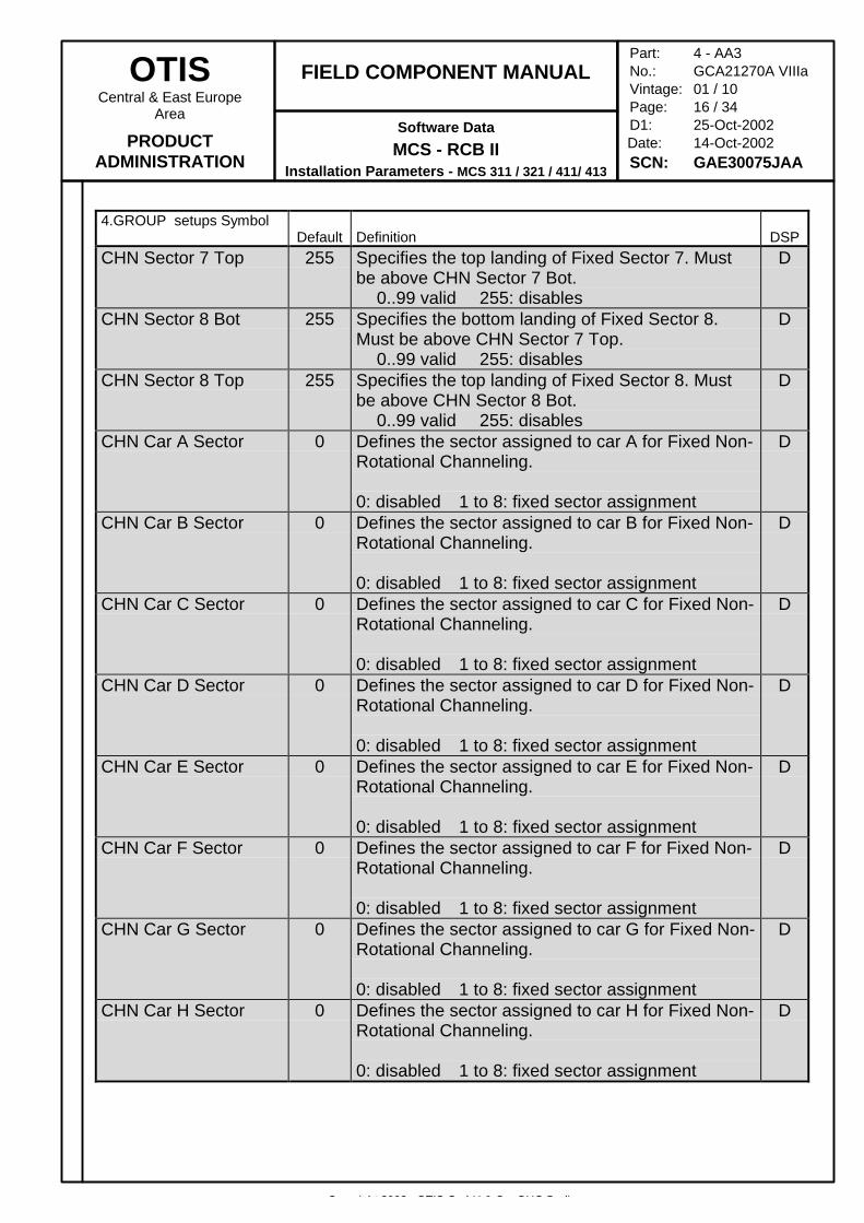
CHN Sector 7 Top 255 Specifies the top landing of Fixed Sector 7. Mustbe above CHN Sector 7 Bot.
0..99 valid 255: disables
D
CHN Sector 8 Bot 255 Specifies the bottom landing of Fixed Sector 8.Must be above CHN Sector 7 Top.
0..99 valid 255: disables
D
CHN Sector 8 Top 255 Specifies the top landing of Fixed Sector 8. Mustbe above CHN Sector 8 Bot.
0..99 valid 255: disables
D
CHN Car A Sector 0 Defines the sector assigned to car A for Fixed Non-Rotational Channeling.
0: disabled 1 to 8: fixed sector assignment
D
CHN Car B Sector 0 Defines the sector assigned to car B for Fixed Non-Rotational Channeling.
0: disabled 1 to 8: fixed sector assignment
D
CHN Car C Sector 0 Defines the sector assigned to car C for Fixed Non-Rotational Channeling.
0: disabled 1 to 8: fixed sector assignment
D
CHN Car D Sector 0 Defines the sector assigned to car D for Fixed Non-Rotational Channeling.
0: disabled 1 to 8: fixed sector assignment
D
CHN Car E Sector 0 Defines the sector assigned to car E for Fixed Non-Rotational Channeling.
0: disabled 1 to 8: fixed sector assignment
D
CHN Car F Sector 0 Defines the sector assigned to car F for Fixed Non-Rotational Channeling.
0: disabled 1 to 8: fixed sector assignment
D
CHN Car G Sector 0 Defines the sector assigned to car G for Fixed Non-Rotational Channeling.
0: disabled 1 to 8: fixed sector assignment
D
CHN Car H Sector 0 Defines the sector assigned to car H for Fixed Non-Rotational Channeling.
0: disabled 1 to 8: fixed sector assignment
D
Copyright 2002, OTIS GmbH & Co. OHG Berlin
OTISCentral & East Europe
Area
PRODUCTADMINISTRATION
FIELD COMPONENT MANUAL
Software Data
MCS - RCB IIInstallation Parameters - MCS 311 / 321 / 411/ 413
Part: 4 - AA3No.: GCA21270A VIIIaVintage: 01 / 10Page: 17 / 34D1: 25-Oct-2002
Date: 14-Oct-2002SCN: GAE30075JAA
4.GROUP setups SymbolDefault Definition DSP
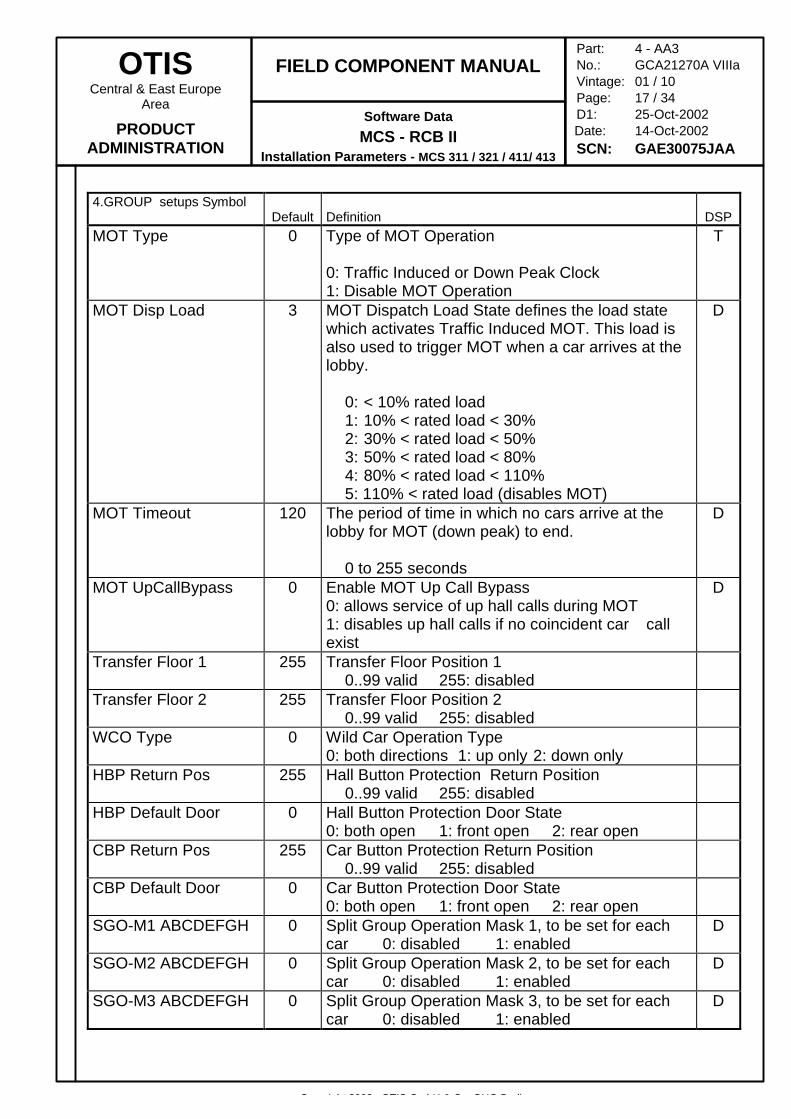
MOT Type 0 Type of MOT Operation
0: Traffic Induced or Down Peak Clock1: Disable MOT Operation
T
MOT Disp Load 3 MOT Dispatch Load State defines the load statewhich activates Traffic Induced MOT. This load isalso used to trigger MOT when a car arrives at thelobby.
0: < 10% rated load1: 10% < rated load < 30%2: 30% < rated load < 50%3: 50% < rated load < 80%4: 80% < rated load < 110%5: 110% < rated load (disables MOT)
D
MOT Timeout 120 The period of time in which no cars arrive at thelobby for MOT (down peak) to end.
0 to 255 seconds
D
MOT UpCallBypass 0 Enable MOT Up Call Bypass0: allows service of up hall calls during MOT1: disables up hall calls if no coincident car callexist
D
Transfer Floor 1 255 Transfer Floor Position 10..99 valid 255: disabled
Transfer Floor 2 255 Transfer Floor Position 20..99 valid 255: disabled
WCO Type 0 Wild Car Operation Type0: both directions 1: up only 2: down only
HBP Return Pos 255 Hall Button Protection Return Position0..99 valid 255: disabled
HBP Default Door 0 Hall Button Protection Door State0: both open 1: front open 2: rear open
CBP Return Pos 255 Car Button Protection Return Position0..99 valid 255: disabled
CBP Default Door 0 Car Button Protection Door State0: both open 1: front open 2: rear open
SGO-M1 ABCDEFGH 0 Split Group Operation Mask 1, to be set for eachcar 0: disabled 1: enabled
D
SGO-M2 ABCDEFGH 0 Split Group Operation Mask 2, to be set for eachcar 0: disabled 1: enabled
D
SGO-M3 ABCDEFGH 0 Split Group Operation Mask 3, to be set for eachcar 0: disabled 1: enabled
D
Copyright 2002, OTIS GmbH & Co. OHG Berlin
OTISCentral & East Europe
Area
PRODUCTADMINISTRATION
FIELD COMPONENT MANUAL
Software Data
MCS - RCB IIInstallation Parameters - MCS 311 / 321 / 411/ 413
Part: 4 - AA3No.: GCA21270A VIIIaVintage: 01 / 10Page: 18 / 34D1: 25-Oct-2002
Date: 14-Oct-2002SCN: GAE30075JAA
4.GROUP setups SymbolDefault Definition DSP
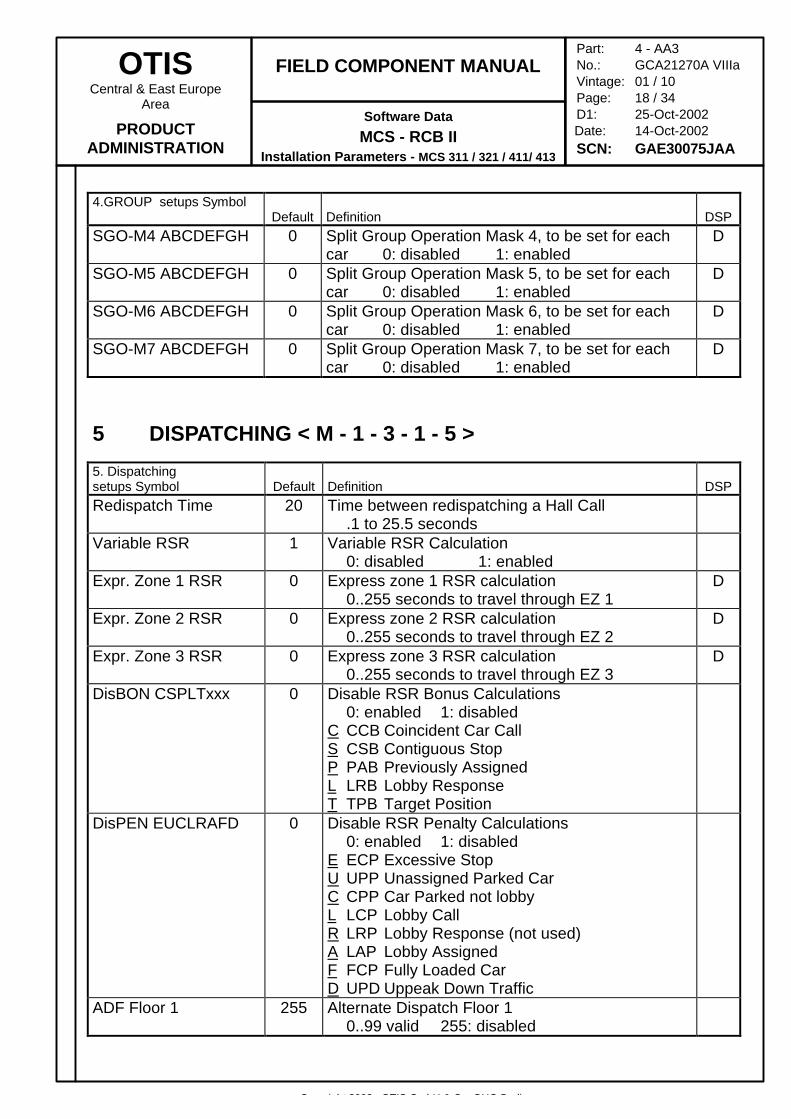
SGO-M4 ABCDEFGH 0 Split Group Operation Mask 4, to be set for eachcar 0: disabled 1: enabled
D
SGO-M5 ABCDEFGH 0 Split Group Operation Mask 5, to be set for eachcar 0: disabled 1: enabled
D
SGO-M6 ABCDEFGH 0 Split Group Operation Mask 6, to be set for eachcar 0: disabled 1: enabled
D
SGO-M7 ABCDEFGH 0 Split Group Operation Mask 7, to be set for eachcar 0: disabled 1: enabled
D
5 DISPATCHING < M - 1 - 3 - 1 - 5 >
5. Dispatchingsetups Symbol Default Definition DSPRedispatch Time 20 Time between redispatching a Hall Call
.1 to 25.5 secondsVariable RSR 1 Variable RSR Calculation
0: disabled 1: enabledExpr. Zone 1 RSR 0 Express zone 1 RSR calculation
0..255 seconds to travel through EZ 1D
Expr. Zone 2 RSR 0 Express zone 2 RSR calculation0..255 seconds to travel through EZ 2
D
Expr. Zone 3 RSR 0 Express zone 3 RSR calculation0..255 seconds to travel through EZ 3
D
DisBON CSPLTxxx 0 Disable RSR Bonus Calculations0: enabled 1: disabled
C CCB Coincident Car CallS CSB Contiguous StopP PAB Previously AssignedL LRB Lobby ResponseT TPB Target Position
DisPEN EUCLRAFD 0 Disable RSR Penalty Calculations0: enabled 1: disabled
E ECP Excessive StopU UPP Unassigned Parked CarC CPP Car Parked not lobbyL LCP Lobby CallR LRP Lobby Response (not used)A LAP Lobby AssignedF FCP Fully Loaded CarD UPD Uppeak Down Traffic
ADF Floor 1 255 Alternate Dispatch Floor 10..99 valid 255: disabled
Copyright 2002, OTIS GmbH & Co. OHG Berlin
OTISCentral & East Europe
Area
PRODUCTADMINISTRATION
FIELD COMPONENT MANUAL
Software Data
MCS - RCB IIInstallation Parameters - MCS 311 / 321 / 411/ 413
Part: 4 - AA3No.: GCA21270A VIIIaVintage: 01 / 10Page: 19 / 34D1: 25-Oct-2002
Date: 14-Oct-2002SCN: GAE30075JAA
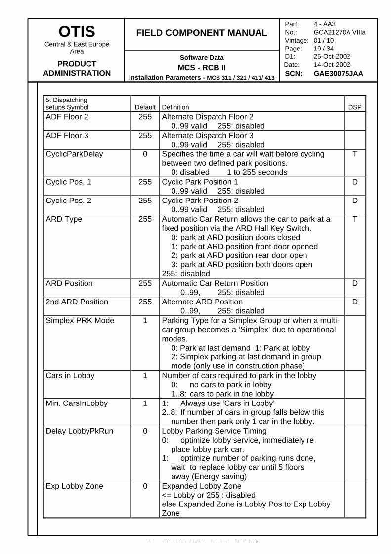
5. Dispatchingsetups Symbol Default Definition DSPADF Floor 2 255 Alternate Dispatch Floor 2
0..99 valid 255: disabledADF Floor 3 255 Alternate Dispatch Floor 3
0..99 valid 255: disabledCyclicParkDelay 0 Specifies the time a car will wait before cycling
between two defined park positions.0: disabled 1 to 255 seconds
T
Cyclic Pos. 1 255 Cyclic Park Position 10..99 valid 255: disabled
D
Cyclic Pos. 2 255 Cyclic Park Position 20..99 valid 255: disabled
D
ARD Type 255 Automatic Car Return allows the car to park at afixed position via the ARD Hall Key Switch.
0: park at ARD position doors closed1: park at ARD position front door opened2: park at ARD position rear door open3: park at ARD position both doors open
255: disabled
T
ARD Position 255 Automatic Car Return Position0..99, 255: disabled
D
2nd ARD Position 255 Alternate ARD Position0..99, 255: disabled
D
Simplex PRK Mode 1 Parking Type for a Simplex Group or when a multi-car group becomes a ‘Simplex’ due to operationalmodes.
0: Park at last demand 1: Park at lobby2: Simplex parking at last demand in group mode (only use in construction phase)
Cars in Lobby 1 Number of cars required to park in the lobby0: no cars to park in lobby1..8: cars to park in the lobby
Min. CarsInLobby 1 1: Always use ‘Cars in Lobby’2..8: If number of cars in group falls below this
number then park only 1 car in the lobby.Delay LobbyPkRun 0 Lobby Parking Service Timing
0: optimize lobby service, immediately replace lobby park car.
1: optimize number of parking runs done, wait to replace lobby car until 5 floors away (Energy saving)
Exp Lobby Zone 0 Expanded Lobby Zone<= Lobby or 255 : disabledelse Expanded Zone is Lobby Pos to Exp LobbyZone
Copyright 2002, OTIS GmbH & Co. OHG Berlin
OTISCentral & East Europe
Area
PRODUCTADMINISTRATION
FIELD COMPONENT MANUAL
Software Data
MCS - RCB IIInstallation Parameters - MCS 311 / 321 / 411/ 413
Part: 4 - AA3No.: GCA21270A VIIIaVintage: 01 / 10Page: 20 / 34D1: 25-Oct-2002
Date: 14-Oct-2002SCN: GAE30075JAA
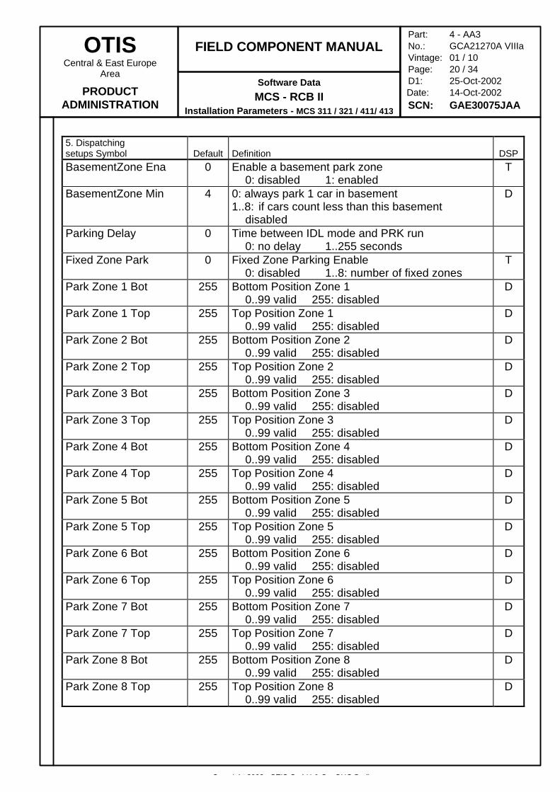
5. Dispatchingsetups Symbol Default Definition DSPBasementZone Ena 0 Enable a basement park zone
0: disabled 1: enabledT
BasementZone Min 4 0: always park 1 car in basement1..8: if cars count less than this basement
disabled
D
Parking Delay 0 Time between IDL mode and PRK run0: no delay 1..255 seconds
Fixed Zone Park 0 Fixed Zone Parking Enable0: disabled 1..8: number of fixed zones
T
Park Zone 1 Bot 255 Bottom Position Zone 10..99 valid 255: disabled
D
Park Zone 1 Top 255 Top Position Zone 10..99 valid 255: disabled
D
Park Zone 2 Bot 255 Bottom Position Zone 20..99 valid 255: disabled
D
Park Zone 2 Top 255 Top Position Zone 20..99 valid 255: disabled
D
Park Zone 3 Bot 255 Bottom Position Zone 30..99 valid 255: disabled
D
Park Zone 3 Top 255 Top Position Zone 30..99 valid 255: disabled
D
Park Zone 4 Bot 255 Bottom Position Zone 40..99 valid 255: disabled
D
Park Zone 4 Top 255 Top Position Zone 40..99 valid 255: disabled
D
Park Zone 5 Bot 255 Bottom Position Zone 50..99 valid 255: disabled
D
Park Zone 5 Top 255 Top Position Zone 50..99 valid 255: disabled
D
Park Zone 6 Bot 255 Bottom Position Zone 60..99 valid 255: disabled
D
Park Zone 6 Top 255 Top Position Zone 60..99 valid 255: disabled
D
Park Zone 7 Bot 255 Bottom Position Zone 70..99 valid 255: disabled
D
Park Zone 7 Top 255 Top Position Zone 70..99 valid 255: disabled
D
Park Zone 8 Bot 255 Bottom Position Zone 80..99 valid 255: disabled
D
Park Zone 8 Top 255 Top Position Zone 80..99 valid 255: disabled
D
Copyright 2002, OTIS GmbH & Co. OHG Berlin
OTISCentral & East Europe
Area
PRODUCTADMINISTRATION
FIELD COMPONENT MANUAL
Software Data
MCS - RCB IIInstallation Parameters - MCS 311 / 321 / 411/ 413
Part: 4 - AA3No.: GCA21270A VIIIaVintage: 01 / 10Page: 21 / 34D1: 25-Oct-2002
Date: 14-Oct-2002SCN: GAE30075JAA
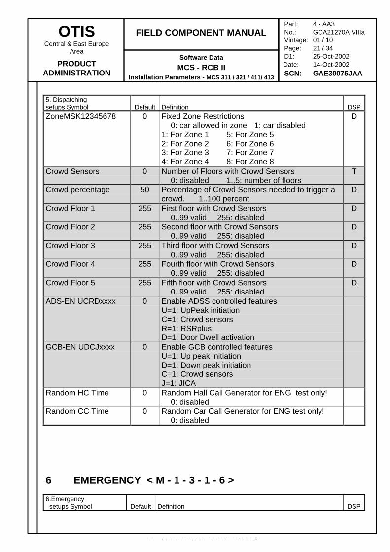
5. Dispatchingsetups Symbol Default Definition DSPZoneMSK12345678 0 Fixed Zone Restrictions
0: car allowed in zone 1: car disabled1: For Zone 1 5: For Zone 52: For Zone 2 6: For Zone 63: For Zone 3 7: For Zone 74: For Zone 4 8: For Zone 8
D
Crowd Sensors 0 Number of Floors with Crowd Sensors0: disabled 1..5: number of floors
T
Crowd percentage 50 Percentage of Crowd Sensors needed to trigger acrowd. 1..100 percent
D
Crowd Floor 1 255 First floor with Crowd Sensors0..99 valid 255: disabled
D
Crowd Floor 2 255 Second floor with Crowd Sensors0..99 valid 255: disabled
D
Crowd Floor 3 255 Third floor with Crowd Sensors0..99 valid 255: disabled
D
Crowd Floor 4 255 Fourth floor with Crowd Sensors0..99 valid 255: disabled
D
Crowd Floor 5 255 Fifth floor with Crowd Sensors0..99 valid 255: disabled
D
ADS-EN UCRDxxxx 0 Enable ADSS controlled featuresU=1: UpPeak initiationC=1: Crowd sensorsR=1: RSRplusD=1: Door Dwell activation
GCB-EN UDCJxxxx 0 Enable GCB controlled featuresU=1: Up peak initiationD=1: Down peak initiationC=1: Crowd sensorsJ=1: JICA
Random HC Time 0 Random Hall Call Generator for ENG test only!0: disabled
Random CC Time 0 Random Car Call Generator for ENG test only!0: disabled
6 EMERGENCY < M - 1 - 3 - 1 - 6 >
6.Emergency setups Symbol Default Definition DSP
Copyright 2002, OTIS GmbH & Co. OHG Berlin
OTISCentral & East Europe
Area
PRODUCTADMINISTRATION
FIELD COMPONENT MANUAL
Software Data
MCS - RCB IIInstallation Parameters - MCS 311 / 321 / 411/ 413
Part: 4 - AA3No.: GCA21270A VIIIaVintage: 01 / 10Page: 22 / 34D1: 25-Oct-2002
Date: 14-Oct-2002SCN: GAE30075JAA
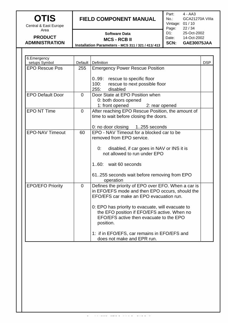
6.Emergency setups Symbol Default Definition DSPEPO Rescue Pos 255 Emergency Power Rescue Position
0..99 : rescue to specific floor100: rescue to next possible floor255: disabled
EPO Default Door 0 Door State at EPO Position when0: both doors opened1: front opened 2: rear opened
EPO NT Time 0 After reaching EPO Rescue Position, the amount oftime to wait before closing the doors.
0: no door closing 1..255 secondsEPO-NAV Timeout 60 EPO - NAV Timeout for a blocked car to be
removed from EPO service.
0: disabled, if car goes in NAV or INS it is not allowed to run under EPO
1..60: wait 60 seconds
61..255 seconds wait before removing from EPO operation
EPO/EFO Priority 0 Defines the priority of EPO over EFO. When a car isin EFO/EFS mode and then EPO occurs, should theEFO/EFS car make an EPO evacuation run.
0: EPO has priority to evacuate, will evacuate to the EFO position if EFO/EFS active. When no EFO/EFS active then evacuate to the EPO position.
1: if in EFO/EFS, car remains in EFO/EFS and does not make and EPR run.
Copyright 2002, OTIS GmbH & Co. OHG Berlin
OTISCentral & East Europe
Area
PRODUCTADMINISTRATION
FIELD COMPONENT MANUAL
Software Data
MCS - RCB IIInstallation Parameters - MCS 311 / 321 / 411/ 413
Part: 4 - AA3No.: GCA21270A VIIIaVintage: 01 / 10Page: 23 / 34D1: 25-Oct-2002
Date: 14-Oct-2002SCN: GAE30075JAA
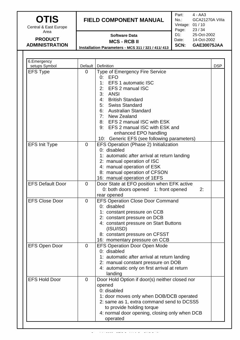
6.Emergency setups Symbol Default Definition DSPEFS Type 0 Type of Emergency Fire Service
0: EFO 1: EFS 1 automatic ISC 2: EFS 2 manual ISC 3: ANSI 4: British Standard 5: Swiss Standard 6: Australian Standard 7: New Zealand 8: EFS 2 manual ISC with ESK 9: EFS 2 manual ISC with ESK and
enhanced EPO handling 10: Generic EFS (see following parameters)
EFS Init Type 0 EFS Operation (Phase 2) Initialization 0: disabled 1: automatic after arrival at return landing 2: manual operation of ISC 4: manual operation of ESK 8: manual operation of CFSON16: manual operation of 1EFS
EFS Default Door 0 Door State at EFO position when EFK active0: both doors opened 1: front opened 2:
rear openedEFS Close Door 0 EFS Operation Close Door Command
0: disabled 1: constant pressure on CCB 2: constant pressure on DCB 4: constant pressure on Start Buttons (ISU/ISD) 8: constant pressure on CFSST16: momentary pressure on CCB
EFS Open Door 0 EFS Operation Door Open Mode 0: disabled 1: automatic after arrival at return landing 2: manual constant pressure on DOB 4: automatic only on first arrival at return landing
EFS Hold Door 0 Door Hold Option if door(s) neither closed noropened 0: disabled 1: door moves only when DOB/DCB operated 2: same as 1, extra command send to DCSS5 to provide holding torque 4: normal door opening, closing only when DCB operated
Copyright 2002, OTIS GmbH & Co. OHG Berlin
OTISCentral & East Europe
Area
PRODUCTADMINISTRATION
FIELD COMPONENT MANUAL
Software Data
MCS - RCB IIInstallation Parameters - MCS 311 / 321 / 411/ 413
Part: 4 - AA3No.: GCA21270A VIIIaVintage: 01 / 10Page: 24 / 34D1: 25-Oct-2002
Date: 14-Oct-2002SCN: GAE30075JAA
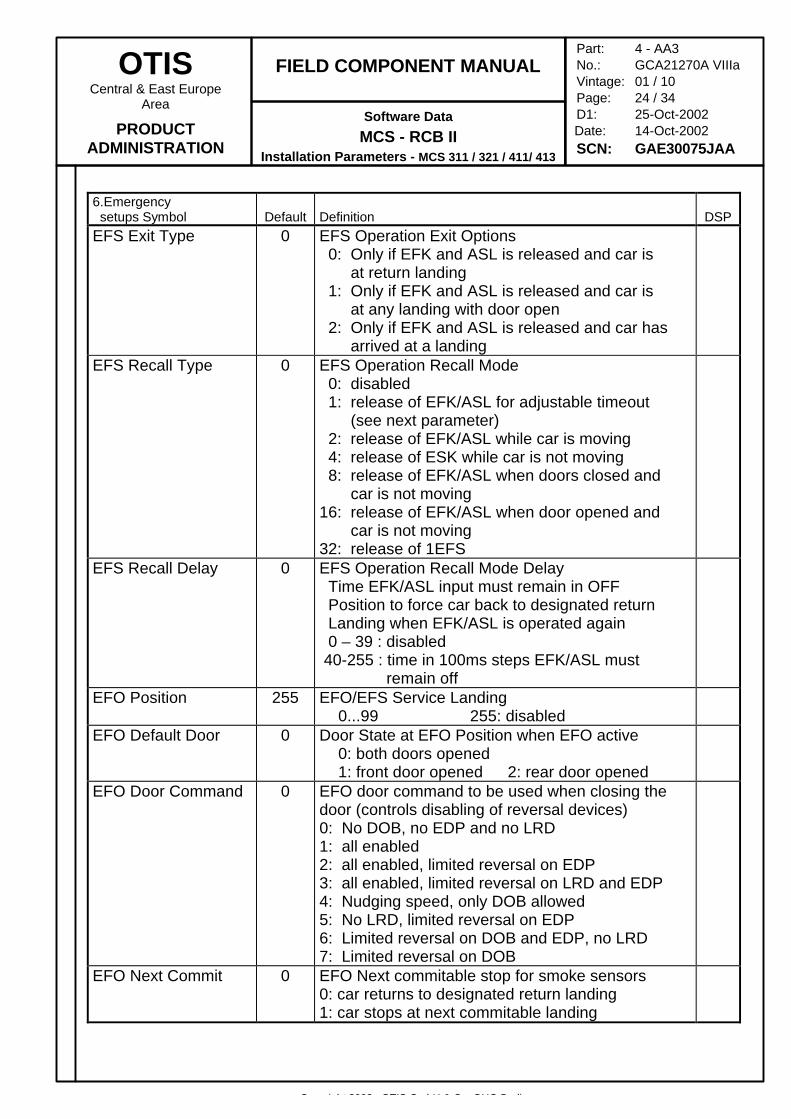
6.Emergency setups Symbol Default Definition DSPEFS Exit Type 0 EFS Operation Exit Options
0: Only if EFK and ASL is released and car is at return landing 1: Only if EFK and ASL is released and car is at any landing with door open 2: Only if EFK and ASL is released and car has arrived at a landing
EFS Recall Type 0 EFS Operation Recall Mode 0: disabled 1: release of EFK/ASL for adjustable timeout (see next parameter) 2: release of EFK/ASL while car is moving 4: release of ESK while car is not moving 8: release of EFK/ASL when doors closed and car is not moving16: release of EFK/ASL when door opened and car is not moving32: release of 1EFS
EFS Recall Delay 0 EFS Operation Recall Mode Delay Time EFK/ASL input must remain in OFF Position to force car back to designated return Landing when EFK/ASL is operated again 0 – 39 : disabled 40-255 : time in 100ms steps EFK/ASL must remain off
EFO Position 255 EFO/EFS Service Landing0...99 255: disabled
EFO Default Door 0 Door State at EFO Position when EFO active0: both doors opened1: front door opened 2: rear door opened
EFO Door Command 0 EFO door command to be used when closing thedoor (controls disabling of reversal devices)0: No DOB, no EDP and no LRD1: all enabled2: all enabled, limited reversal on EDP3: all enabled, limited reversal on LRD and EDP4: Nudging speed, only DOB allowed5: No LRD, limited reversal on EDP6: Limited reversal on DOB and EDP, no LRD7: Limited reversal on DOB
EFO Next Commit 0 EFO Next commitable stop for smoke sensors0: car returns to designated return landing1: car stops at next commitable landing
Copyright 2002, OTIS GmbH & Co. OHG Berlin
OTISCentral & East Europe
Area
PRODUCTADMINISTRATION
FIELD COMPONENT MANUAL
Software Data
MCS - RCB IIInstallation Parameters - MCS 311 / 321 / 411/ 413
Part: 4 - AA3No.: GCA21270A VIIIaVintage: 01 / 10Page: 25 / 34D1: 25-Oct-2002
Date: 14-Oct-2002SCN: GAE30075JAA
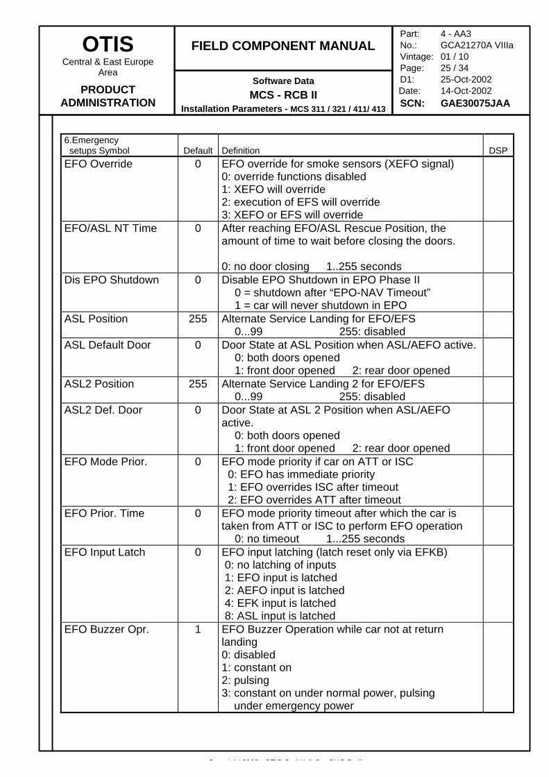
6.Emergency setups Symbol Default Definition DSPEFO Override 0 EFO override for smoke sensors (XEFO signal)
0: override functions disabled1: XEFO will override2: execution of EFS will override3: XEFO or EFS will override
EFO/ASL NT Time 0 After reaching EFO/ASL Rescue Position, theamount of time to wait before closing the doors.
0: no door closing 1..255 secondsDis EPO Shutdown 0 Disable EPO Shutdown in EPO Phase II
0 = shutdown after “EPO-NAV Timeout”1 = car will never shutdown in EPO
ASL Position 255 Alternate Service Landing for EFO/EFS0...99 255: disabled
ASL Default Door 0 Door State at ASL Position when ASL/AEFO active.0: both doors opened1: front door opened 2: rear door opened
ASL2 Position 255 Alternate Service Landing 2 for EFO/EFS0...99 255: disabled
ASL2 Def. Door 0 Door State at ASL 2 Position when ASL/AEFOactive.
0: both doors opened1: front door opened 2: rear door opened
EFO Mode Prior. 0 EFO mode priority if car on ATT or ISC 0: EFO has immediate priority 1: EFO overrides ISC after timeout 2: EFO overrides ATT after timeout
EFO Prior. Time 0 EFO mode priority timeout after which the car istaken from ATT or ISC to perform EFO operation
0: no timeout 1...255 secondsEFO Input Latch 0 EFO input latching (latch reset only via EFKB)
0: no latching of inputs 1: EFO input is latched 2: AEFO input is latched 4: EFK input is latched 8: ASL input is latched
EFO Buzzer Opr. 1 EFO Buzzer Operation while car not at returnlanding0: disabled1: constant on2: pulsing3: constant on under normal power, pulsing under emergency power

Copyright 2002, OTIS GmbH & Co. OHG Berlin
OTISCentral & East Europe
Area
PRODUCTADMINISTRATION
FIELD COMPONENT MANUAL
Software Data
MCS - RCB IIInstallation Parameters - MCS 311 / 321 / 411/ 413
Part: 4 - AA3No.: GCA21270A VIIIaVintage: 01 / 10Page: 26 / 34D1: 25-Oct-2002
Date: 14-Oct-2002SCN: GAE30075JAA
6.Emergency setups Symbol Default Definition DSPResetBut ACEIxxx 0 Reset Button Options in following Modes
A: ATT Mode0: disabled 1: enabled
C: CHCS mode0: disabled 1: enabled
E: EFS Mode0: disabled 1: enabled
I: ISC Mode0: disabled 1: enabled
EPS Enable type 0 Enable Express Priority Service0: disabled 1: enabled
EPS PhaseI Type 0 Express Priority Service Phase I0: serve EHS call immediately1: stop at next commitable floor first2: serve entered car calls en route3: serve all existing car calls
EPS Phase II Type 0 Express Priority Service Phase II0: automatic ISC for one run1: immediately return to normal after run2: automatic CHCS for one run
EPS Timeout 30 Express Priority Service Timeout0: no timeout 1...255 seconds
EMT PhaseI Type 0 Emergency Medical Transportation Phase I0: serve EHS call immediately1: stop at next commitable floor first2: serve entered car calls en route3: serve all existing car calls
EMT Phase II Type 0 Emergency Medical Transportation Phase II0: automatic ISC for one run1: immediately return to normal after run2: automatic CHCS for one run
EMT Timeout 30 Emergency Medical Transportation Timeout0: no timeout 1...255 seconds
FPD Enable 0 Fire Proof Doors Enabled0: Disabled 1: Car Link 2: Group Link
FPD Prefered Dir 0 Fire Proof Doors Preferred Direction0: Go in up direction to accessible Landing
1: Go down to accessible LandingFPD to force EFO 0 FPD Contacts used as smoke sensors to force EFO
operation0: no automatic EFO when FPD operated
1 – 100: number (count) of FPD Contactsoperated at the same time to force EFO
Copyright 2002, OTIS GmbH & Co. OHG Berlin
OTISCentral & East Europe
Area
PRODUCTADMINISTRATION
FIELD COMPONENT MANUAL
Software Data
MCS - RCB IIInstallation Parameters - MCS 311 / 321 / 411/ 413
Part: 4 - AA3No.: GCA21270A VIIIaVintage: 01 / 10Page: 27 / 34D1: 25-Oct-2002
Date: 14-Oct-2002SCN: GAE30075JAA
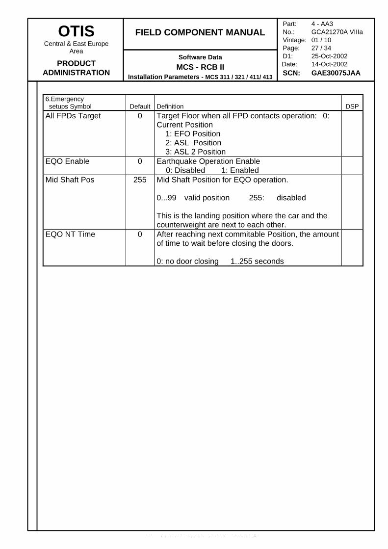
6.Emergency setups Symbol Default Definition DSPAll FPDs Target 0 Target Floor when all FPD contacts operation: 0:
Current Position 1: EFO Position 2: ASL Position 3: ASL 2 Position
EQO Enable 0 Earthquake Operation Enable0: Disabled 1: Enabled
Mid Shaft Pos 255 Mid Shaft Position for EQO operation.
0...99 valid position 255: disabled
This is the landing position where the car and thecounterweight are next to each other.
EQO NT Time 0 After reaching next commitable Position, the amountof time to wait before closing the doors.
0: no door closing 1..255 seconds
Copyright 2002, OTIS GmbH & Co. OHG Berlin
OTISCentral & East Europe
Area
PRODUCTADMINISTRATION
FIELD COMPONENT MANUAL
Software Data
MCS - RCB IIInstallation Parameters - MCS 311 / 321 / 411/ 413
Part: 4 - AA3No.: GCA21270A VIIIaVintage: 01 / 10Page: 28 / 34D1: 25-Oct-2002
Date: 14-Oct-2002SCN: GAE30075JAA
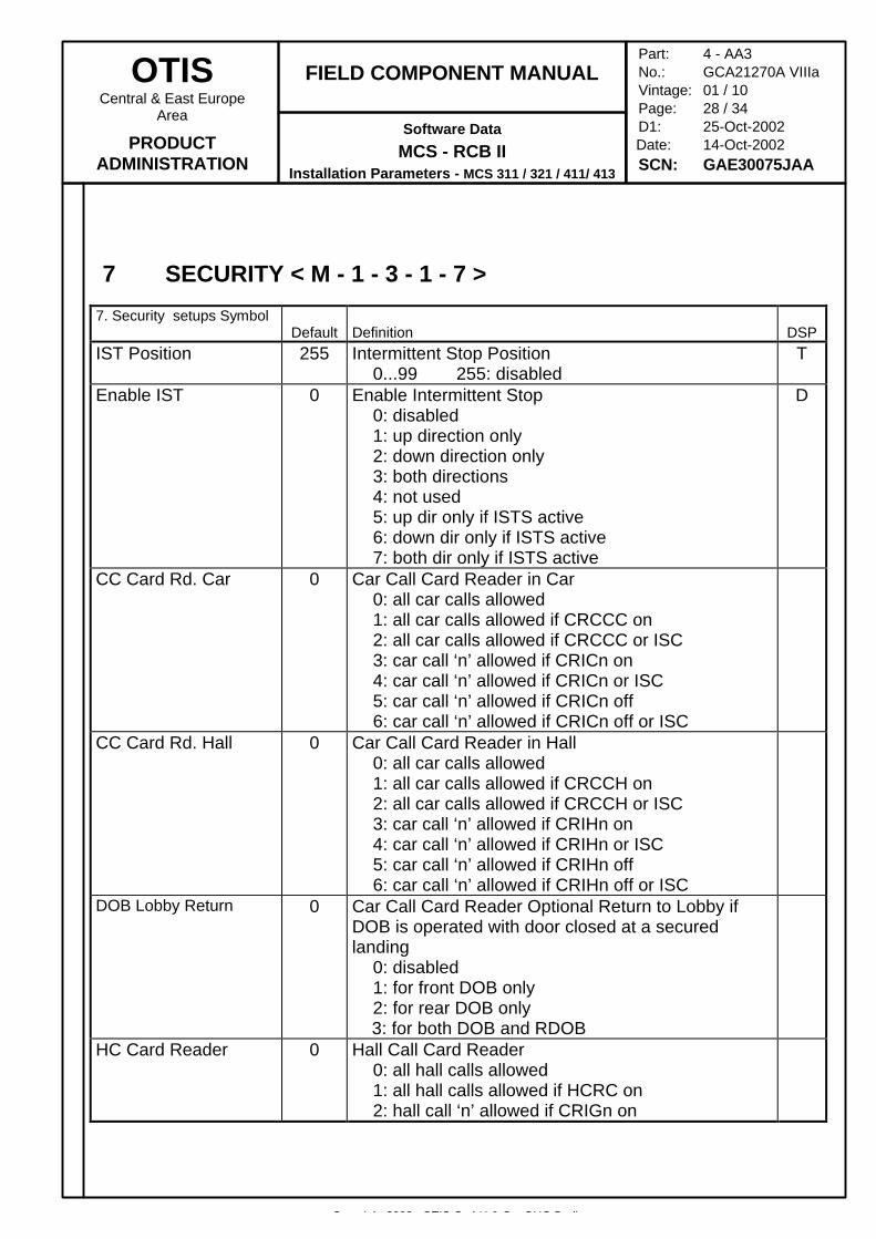
7 SECURITY < M - 1 - 3 - 1 - 7 >
7. Security setups SymbolDefault Definition DSP
IST Position 255 Intermittent Stop Position0...99 255: disabled
T
Enable IST 0 Enable Intermittent Stop0: disabled1: up direction only2: down direction only3: both directions4: not used5: up dir only if ISTS active6: down dir only if ISTS active7: both dir only if ISTS active
D
CC Card Rd. Car 0 Car Call Card Reader in Car0: all car calls allowed1: all car calls allowed if CRCCC on2: all car calls allowed if CRCCC or ISC3: car call ‘n’ allowed if CRICn on4: car call ‘n’ allowed if CRICn or ISC5: car call ‘n’ allowed if CRICn off6: car call ‘n’ allowed if CRICn off or ISC
CC Card Rd. Hall 0 Car Call Card Reader in Hall0: all car calls allowed1: all car calls allowed if CRCCH on2: all car calls allowed if CRCCH or ISC3: car call ‘n’ allowed if CRIHn on4: car call ‘n’ allowed if CRIHn or ISC5: car call ‘n’ allowed if CRIHn off6: car call ‘n’ allowed if CRIHn off or ISC
DOB Lobby Return 0 Car Call Card Reader Optional Return to Lobby ifDOB is operated with door closed at a securedlanding
0: disabled1: for front DOB only2: for rear DOB only
3: for both DOB and RDOBHC Card Reader 0 Hall Call Card Reader
0: all hall calls allowed1: all hall calls allowed if HCRC on2: hall call ‘n’ allowed if CRIGn on
Copyright 2002, OTIS GmbH & Co. OHG Berlin
OTISCentral & East Europe
Area
PRODUCTADMINISTRATION
FIELD COMPONENT MANUAL
Software Data
MCS - RCB IIInstallation Parameters - MCS 311 / 321 / 411/ 413
Part: 4 - AA3No.: GCA21270A VIIIaVintage: 01 / 10Page: 29 / 34D1: 25-Oct-2002
Date: 14-Oct-2002SCN: GAE30075JAA
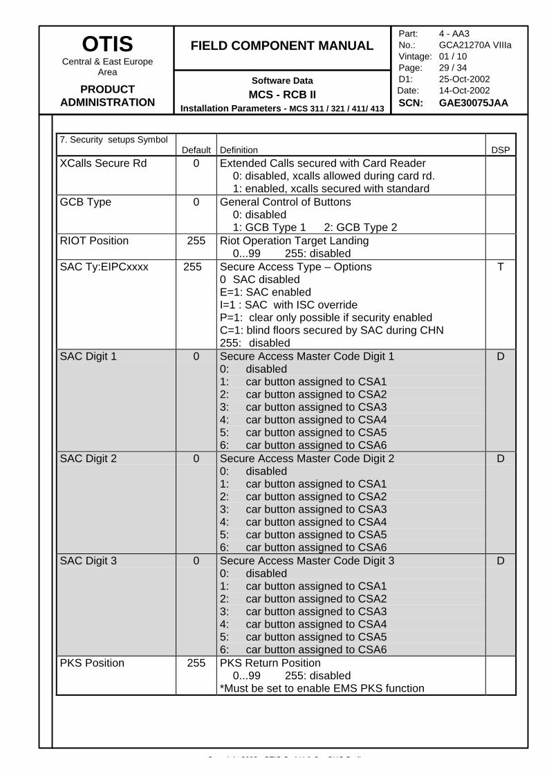
7. Security setups SymbolDefault Definition DSP
XCalls Secure Rd 0 Extended Calls secured with Card Reader0: disabled, xcalls allowed during card rd.1: enabled, xcalls secured with standard
GCB Type 0 General Control of Buttons0: disabled1: GCB Type 1 2: GCB Type 2
RIOT Position 255 Riot Operation Target Landing0...99 255: disabled
SAC Ty:EIPCxxxx 255 Secure Access Type – Options0 SAC disabledE=1: SAC enabledI=1 : SAC with ISC overrideP=1: clear only possible if security enabledC=1: blind floors secured by SAC during CHN255: disabled
T
SAC Digit 1 0 Secure Access Master Code Digit 10: disabled1: car button assigned to CSA12: car button assigned to CSA23: car button assigned to CSA34: car button assigned to CSA45: car button assigned to CSA56: car button assigned to CSA6
D
SAC Digit 2 0 Secure Access Master Code Digit 20: disabled1: car button assigned to CSA12: car button assigned to CSA23: car button assigned to CSA34: car button assigned to CSA45: car button assigned to CSA56: car button assigned to CSA6
D
SAC Digit 3 0 Secure Access Master Code Digit 30: disabled1: car button assigned to CSA12: car button assigned to CSA23: car button assigned to CSA34: car button assigned to CSA45: car button assigned to CSA56: car button assigned to CSA6
D
PKS Position 255 PKS Return Position0...99 255: disabled
*Must be set to enable EMS PKS function
Copyright 2002, OTIS GmbH & Co. OHG Berlin
OTISCentral & East Europe
Area
PRODUCTADMINISTRATION
FIELD COMPONENT MANUAL
Software Data
MCS - RCB IIInstallation Parameters - MCS 311 / 321 / 411/ 413
Part: 4 - AA3No.: GCA21270A VIIIaVintage: 01 / 10Page: 30 / 34D1: 25-Oct-2002
Date: 14-Oct-2002SCN: GAE30075JAA
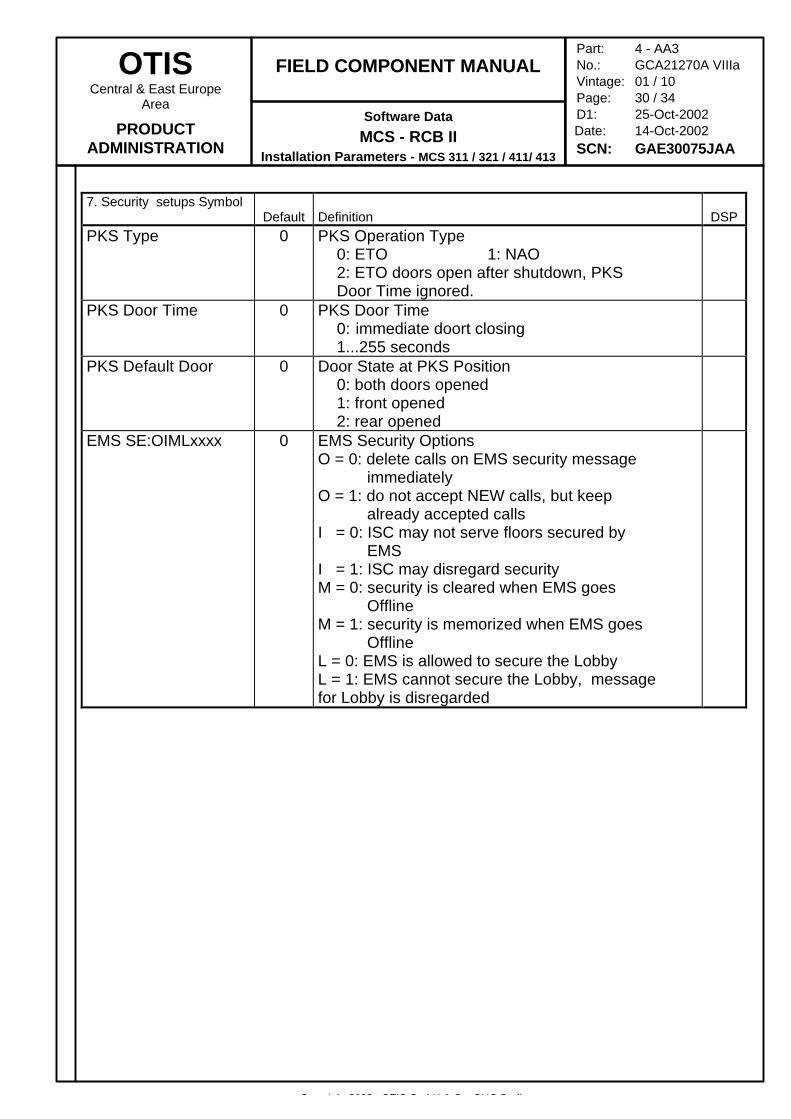
7. Security setups SymbolDefault Definition DSP
PKS Type 0 PKS Operation Type0: ETO 1: NAO2: ETO doors open after shutdown, PKS Door Time ignored.
PKS Door Time 0 PKS Door Time0: immediate doort closing1...255 seconds
PKS Default Door 0 Door State at PKS Position0: both doors opened1: front opened2: rear opened
EMS SE:OIMLxxxx 0 EMS Security OptionsO = 0: delete calls on EMS security message immediatelyO = 1: do not accept NEW calls, but keep already accepted callsI = 0: ISC may not serve floors secured by EMSI = 1: ISC may disregard securityM = 0: security is cleared when EMS goes OfflineM = 1: security is memorized when EMS goes OfflineL = 0: EMS is allowed to secure the LobbyL = 1: EMS cannot secure the Lobby, message for Lobby is disregarded
Copyright 2002, OTIS GmbH & Co. OHG Berlin
OTISCentral & East Europe
Area
PRODUCTADMINISTRATION
FIELD COMPONENT MANUAL
Software Data
MCS - RCB IIInstallation Parameters - MCS 311 / 321 / 411/ 413
Part: 4 - AA3No.: GCA21270A VIIIaVintage: 01 / 10Page: 31 / 34D1: 25-Oct-2002
Date: 14-Oct-2002SCN: GAE30075JAA
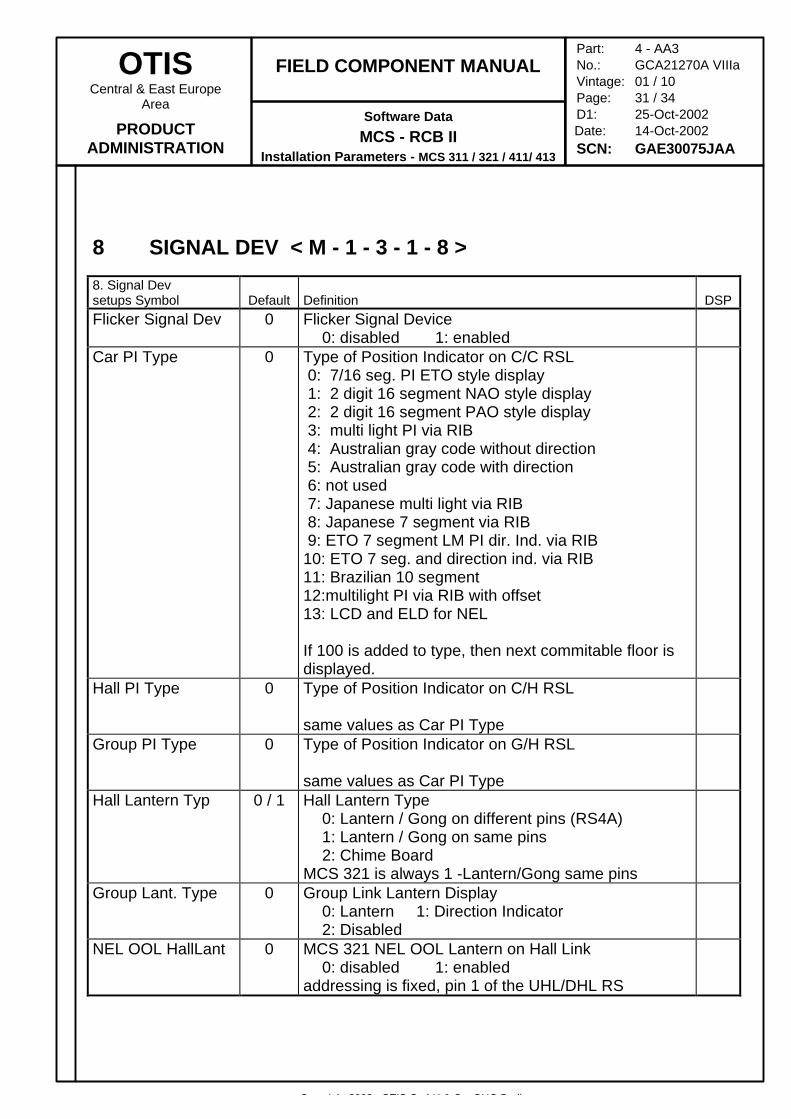
8 SIGNAL DEV < M - 1 - 3 - 1 - 8 >
8. Signal Devsetups Symbol Default Definition DSPFlicker Signal Dev 0 Flicker Signal Device
0: disabled 1: enabledCar PI Type 0 Type of Position Indicator on C/C RSL
0: 7/16 seg. PI ETO style display 1: 2 digit 16 segment NAO style display 2: 2 digit 16 segment PAO style display 3: multi light PI via RIB 4: Australian gray code without direction 5: Australian gray code with direction 6: not used 7: Japanese multi light via RIB 8: Japanese 7 segment via RIB 9: ETO 7 segment LM PI dir. Ind. via RIB10: ETO 7 seg. and direction ind. via RIB11: Brazilian 10 segment12:multilight PI via RIB with offset13: LCD and ELD for NEL
If 100 is added to type, then next commitable floor isdisplayed.
Hall PI Type 0 Type of Position Indicator on C/H RSL
same values as Car PI TypeGroup PI Type 0 Type of Position Indicator on G/H RSL
same values as Car PI TypeHall Lantern Typ 0 / 1 Hall Lantern Type
0: Lantern / Gong on different pins (RS4A)1: Lantern / Gong on same pins2: Chime Board
MCS 321 is always 1 -Lantern/Gong same pinsGroup Lant. Type 0 Group Link Lantern Display
0: Lantern 1: Direction Indicator2: Disabled
NEL OOL HallLant 0 MCS 321 NEL OOL Lantern on Hall Link0: disabled 1: enabled
addressing is fixed, pin 1 of the UHL/DHL RS
Copyright 2002, OTIS GmbH & Co. OHG Berlin
OTISCentral & East Europe
Area
PRODUCTADMINISTRATION
FIELD COMPONENT MANUAL
Software Data
MCS - RCB IIInstallation Parameters - MCS 311 / 321 / 411/ 413
Part: 4 - AA3No.: GCA21270A VIIIaVintage: 01 / 10Page: 32 / 34D1: 25-Oct-2002
Date: 14-Oct-2002SCN: GAE30075JAA
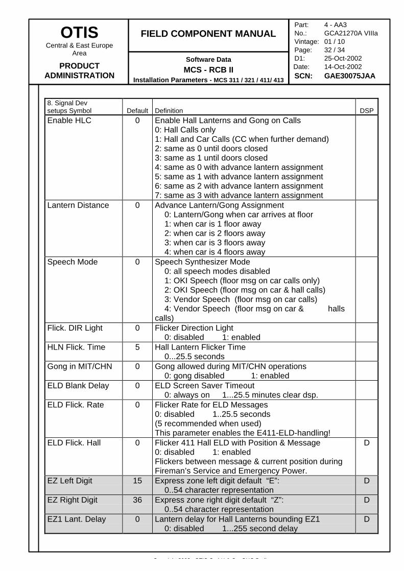
8. Signal Devsetups Symbol Default Definition DSPEnable HLC 0 Enable Hall Lanterns and Gong on Calls
0: Hall Calls only1: Hall and Car Calls (CC when further demand)2: same as 0 until doors closed3: same as 1 until doors closed4: same as 0 with advance lantern assignment5: same as 1 with advance lantern assignment6: same as 2 with advance lantern assignment7: same as 3 with advance lantern assignment
Lantern Distance 0 Advance Lantern/Gong Assignment0: Lantern/Gong when car arrives at floor1: when car is 1 floor away2: when car is 2 floors away3: when car is 3 floors away4: when car is 4 floors away
Speech Mode 0 Speech Synthesizer Mode0: all speech modes disabled1: OKI Speech (floor msg on car calls only)2: OKI Speech (floor msg on car & hall calls)3: Vendor Speech (floor msg on car calls) 4: Vendor Speech (floor msg on car & halls
calls)Flick. DIR Light 0 Flicker Direction Light
0: disabled 1: enabledHLN Flick. Time 5 Hall Lantern Flicker Time
0...25.5 secondsGong in MIT/CHN 0 Gong allowed during MIT/CHN operations
0: gong disabled 1: enabledELD Blank Delay 0 ELD Screen Saver Timeout
0: always on 1...25.5 minutes clear dsp.ELD Flick. Rate 0 Flicker Rate for ELD Messages
0: disabled 1..25.5 seconds(5 recommended when used)This parameter enables the E411-ELD-handling!
ELD Flick. Hall 0 Flicker 411 Hall ELD with Position & Message0: disabled 1: enabledFlickers between message & current position duringFireman’s Service and Emergency Power.
D
EZ Left Digit 15 Express zone left digit default “E”:0..54 character representation
D
EZ Right Digit 36 Express zone right digit default “Z”:0..54 character representation
D
EZ1 Lant. Delay 0 Lantern delay for Hall Lanterns bounding EZ10: disabled 1...255 second delay
D
Copyright 2002, OTIS GmbH & Co. OHG Berlin
OTISCentral & East Europe
Area
PRODUCTADMINISTRATION
FIELD COMPONENT MANUAL
Software Data
MCS - RCB IIInstallation Parameters - MCS 311 / 321 / 411/ 413
Part: 4 - AA3No.: GCA21270A VIIIaVintage: 01 / 10Page: 33 / 34D1: 25-Oct-2002
Date: 14-Oct-2002SCN: GAE30075JAA
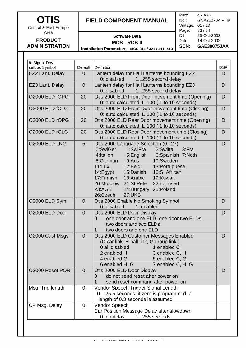
8. Signal Devsetups Symbol Default Definition DSPEZ2 Lant. Delay 0 Lantern delay for Hall Lanterns bounding EZ2
0: disabled 1...255 second delayD
EZ3 Lant. Delay 0 Lantern delay for Hall Lanterns bounding EZ30: disabled 1...255 second delay
D
O2000 ELD fOPG 20 Otis 2000 ELD Front Door movement time (Opening)0: auto calculated 1..100 (.1 to 10 seconds)
D
O2000 ELD fCLG 20 Otis 2000 ELD Front Door movement time (Closing)0: auto calculated 1..100 (.1 to 10 seconds)
D
O2000 ELD rOPG 20 Otis 2000 ELD Rear Door movement time (Opening)0: auto calculated 1..100 (.1 to 10 seconds)
D
O2000 ELD rCLG 20 Otis 2000 ELD Rear Door movement time (Closing)0: auto calculated 1..100 (.1 to 10 seconds)
D
O2000 ELD LNG 5 Otis 2000 Language Selection (0...27) 0:SwiGer 1:SwiFra 2:SwiIta 3:Fra 4:Italien 5:English 6:Spainish 7:Neth 8:German 9:Aus 10:Sweden11:Lux. 12:Belg. 13:Portuguese14:Egypt 15:Danish 16:S. African17:Finnish 18:Arabic 19:Kuwait20:Moscow 21:St.Pete 22:not used23:AGB 24:Hungary 25:Poland26:Czech 27:UKB
D
O2000 ELD Syml 0 Otis 2000 Enable No Smoking Symbol0: disabled 1: enabled
D
O2000 ELD Door 0 Otis 2000 ELD Door Display0 one door and one ELD, one door two ELDs,
two doors and two ELDs1 two doors and one ELD
D
O2000 Cust.Msgs 0 Otis 2000 ELD Customer Messages Enabled(C car link, H hall link, G group link )0 all disabled 1 enabled C2 enabled H 3 enabled C, H4 enabled G 5 enabled C, G6 enabled H, G 7 enabled C, H, G
D
O2000 Reset POR 0 Otis 2000 ELD Door Display0 do not send reset after power on1 send reset command after power on
D
Msg. Trig length 0 Vendor Speech Trigger Signal Length 0 – 25.5 seconds, if zero is programmed, a length of 0.3 seconds is assumed
CP Msg. Delay 0 Vendor SpeechCar Position Message Delay after slowdown
0: no delay 1...255 seconds
Copyright 2002, OTIS GmbH & Co. OHG Berlin
OTISCentral & East Europe
Area
PRODUCTADMINISTRATION
FIELD COMPONENT MANUAL
Software Data
MCS - RCB IIInstallation Parameters - MCS 311 / 321 / 411/ 413
Part: 4 - AA3No.: GCA21270A VIIIaVintage: 01 / 10Page: 34 / 34D1: 25-Oct-2002
Date: 14-Oct-2002SCN: GAE30075JAA
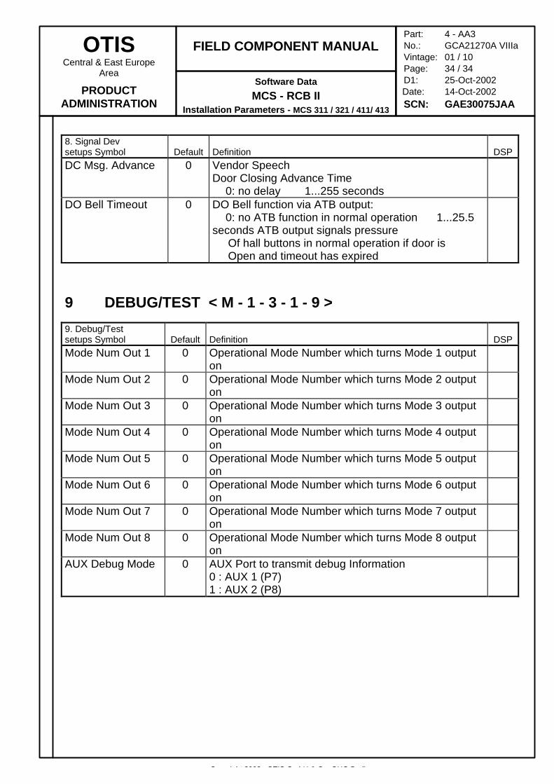
8. Signal Devsetups Symbol Default Definition DSPDC Msg. Advance 0 Vendor Speech
Door Closing Advance Time0: no delay 1...255 seconds
DO Bell Timeout 0 DO Bell function via ATB output:0: no ATB function in normal operation 1...25.5
seconds ATB output signals pressure Of hall buttons in normal operation if door is Open and timeout has expired
9 DEBUG/TEST < M - 1 - 3 - 1 - 9 >
9. Debug/Testsetups Symbol Default Definition DSPMode Num Out 1 0 Operational Mode Number which turns Mode 1 output
onMode Num Out 2 0 Operational Mode Number which turns Mode 2 output
onMode Num Out 3 0 Operational Mode Number which turns Mode 3 output
onMode Num Out 4 0 Operational Mode Number which turns Mode 4 output
onMode Num Out 5 0 Operational Mode Number which turns Mode 5 output
onMode Num Out 6 0 Operational Mode Number which turns Mode 6 output
onMode Num Out 7 0 Operational Mode Number which turns Mode 7 output
onMode Num Out 8 0 Operational Mode Number which turns Mode 8 output
onAUX Debug Mode 0 AUX Port to transmit debug Information
0 : AUX 1 (P7)1 : AUX 2 (P8)


