Download - Manual ip44 popp_en
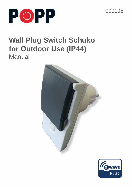
Wall Plug Switch Schukofor Outdoor Use (IP44)Manual
009105
Quick Start...............................................................................................................................................
Product Description.................................................................................................................................
Before Installation....................................................................................................................................
Installation Guidelines.............................................................................................................................
Behavior within the Z-Wave Network......................................................................................................
Operating the Device...............................................................................................................................
Child Protection.......................................................................................................................................
Association..............................................................................................................................................
Configuration Parameters.......................................................................................................................
Command Classes..................................................................................................................................
Technical Data.........................................................................................................................................
Explanation of Z-Wave specific Terms.....................................................................................................
Support....................................................................................................................................................
Wall Plug Switch Schuko (IP44) – Manual
2
2
2
3
3
3
4
4
4
5
6
6
6
2
Quick StartThis is a Z-Wave actuator. Inclusion and Exclusion are confirmed by a triple click of the button. Fast blinking LED indicates the factory reset state.
Please refer to the chapters below for detailed information about all aspects of the products usage.
Product DescriptionThis is a plug switch that can be placed between a wall outlet for Schuko plugs (plug type F) and electric devices, plugged in by cord. It can switch all loads up to 3500 W. The device is IP44 rated and can therefore be used both in dry environments as well as humid environments and outdoor. Switching is controlled wirelessly using Z-Wave or locally applying a button. A multi color LED indicates the switching status and the assignment of the colors to the switching status can be defined by the user. The device will report any change of the switching status to a central gateway regardless the origin of the switch (local or wireless). A built in virtual power meter will report the power consumption of the load attached. However the user must configure the assumed constant power draw of the load. The local button can control the local load but can also be used to control other functions in a Z-Wave network. The device is certified and tested against all important European Safety Regulations and fully complies with the Z-Wave Plus standard. The device supports secure communication and the firmware can be upgraded over the air (OTA).
Before InstallationPlease read carefully the enclosed user manual before installation of the radio-actuator, in order to ensure an error-free functioning.
ATTENTION: Only authorized technicians under consideration of the country-specific installation guidelines/norms may do works with 230 Volt mains power. Prior to the assembly of the product, the voltage network has to be switched off and ensured against re-switching. The product is permitted only for proper use as specified in the user manual. Any kind of guarantee claim has to be forfeited if changes, modifications or painting are undertaken. The product must be checked for damages immediately after unpacking. In the case of damages, the product must not be operated in any case. If a danger-free operation of the equipment cannot be assured, the voltage supply has to be interrupted immediately and the equipment has to be protected from unintended operation.
Installation GuidelinesThe plug can be plugged into every wall outlet for Plug-Type Schuko. It is IP44 rated and can therefore be used both in dry environments as well as humid environments and outdoor. Do not locate the device facing direct sunlight or dusty place. The suitable ambient temperature for the device is 0°C ~ 40°C. Plugs must not be stacked and operated.
Confi guration MenuKeeping the button pressed for 5 seconds will enter the confi guration menu. A blinking blue LED indicates that this menu was entered. Short click of the button will change the confi guration option and a long (min. 2 seconds) click confi rms the selection.
The following options are supported: • Blue: Confi rm fi rmware update• Red: Local reset
Behavior within the Z-Wave NetworkOn factory default the device does not belong to any Z-Wave network. The device needs to join an existing wireless network to communicate with the devices of this network. This process is called Inclusion. Devices can also leave a network. This process is called Exclusion. Both processes are initiated by the primary controller of the Z-Wave network. This controller will be turned into exclusion respective inclusion mode. Please refer to your primary controllers manual on how to turn your controller into inclusion or exclusion mode. Only if the primary controller is in inclusion or exclusion mode, this device can join or leave the network. Leaving the network – i.e. being excluded – sets the device back to factory default.
If the device already belongs to a network, follow the exclusion process before including it in your network. Otherwise inclusion of this device will fail. If the controller being included was a primary controller, it has to be reset fi rst.
Inclusion and Exclusion are confi rmed by a triple click on the button.
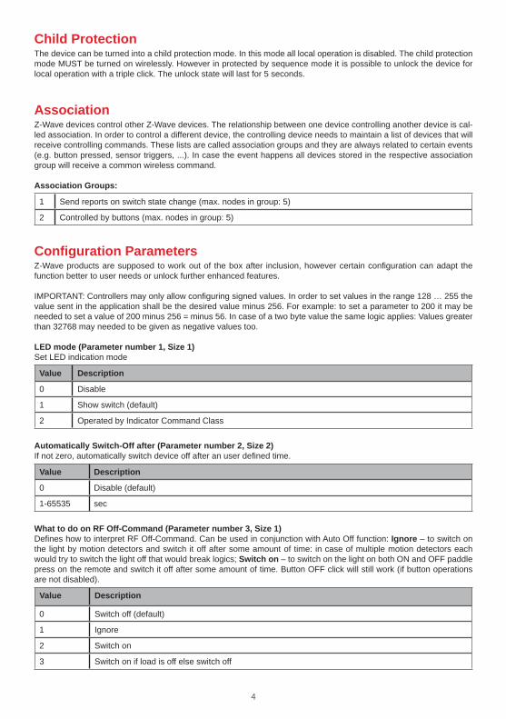
Operating the Device
The device is able to switch electric loads up to 3500 W and can be switched wirelessly or using the local button.
Local OperationThe local button allows to switch the device. A short press on the button toggles the switch. If it is in ON state the button turns off and respective in OFF state the button turns on.
Automated Switch-Off FunctionIf activated the switch will turn off automatically after a defi ned time. This function is particularly useful if the switch is turned on using a motion detector of any other type of sensor. In this case it is possible to further defi ne the reaction of the switch on certain signals sent from a sensor. This allows a very fl exible application of the plug switch in the house.
3
Function Button
Status LED
Function Button
Status LED
Child ProtectionThe device can be turned into a child protection mode. In this mode all local operation is disabled. The child protection mode MUST be turned on wirelessly. However in protected by sequence mode it is possible to unlock the device for local operation with a triple click. The unlock state will last for 5 seconds.
AssociationZ-Wave devices control other Z-Wave devices. The relationship between one device controlling another device is cal-led association. In order to control a different device, the controlling device needs to maintain a list of devices that will receive controlling commands. These lists are called association groups and they are always related to certain events (e.g. button pressed, sensor triggers, ...). In case the event happens all devices stored in the respective association group will receive a common wireless command.
Association Groups:
1 Send reports on switch state change (max. nodes in group: 5)
2 Controlled by buttons (max. nodes in group: 5)
Configuration ParametersZ-Wave products are supposed to work out of the box after inclusion, however certain configuration can adapt the function better to user needs or unlock further enhanced features.
IMPORTANT: Controllers may only allow configuring signed values. In order to set values in the range 128 … 255 the value sent in the application shall be the desired value minus 256. For example: to set a parameter to 200 it may be needed to set a value of 200 minus 256 = minus 56. In case of a two byte value the same logic applies: Values greater than 32768 may needed to be given as negative values too.
LED mode (Parameter number 1, Size 1)Set LED indication mode
Value Description
0 Disable
1 Show switch (default)
2 Operated by Indicator Command Class
Automatically Switch-Off after (Parameter number 2, Size 2)If not zero, automatically switch device off after an user defined time.
Value Description
0 Disable (default)
1-65535 sec
What to do on RF Off-Command (Parameter number 3, Size 1)Defines how to interpret RF Off-Command. Can be used in conjunction with Auto Off function: Ignore – to switch on the light by motion detectors and switch it off after some amount of time: in case of multiple motion detectors each would try to switch the light off that would break logics; Switch on – to switch on the light on both ON and OFF paddle press on the remote and switch it off after some amount of time. Button OFF click will still work (if button operations are not disabled).
Value Description
0 Switch off (default)
1 Ignore
2 Switch on
3 Switch on if load is off else switch off
4
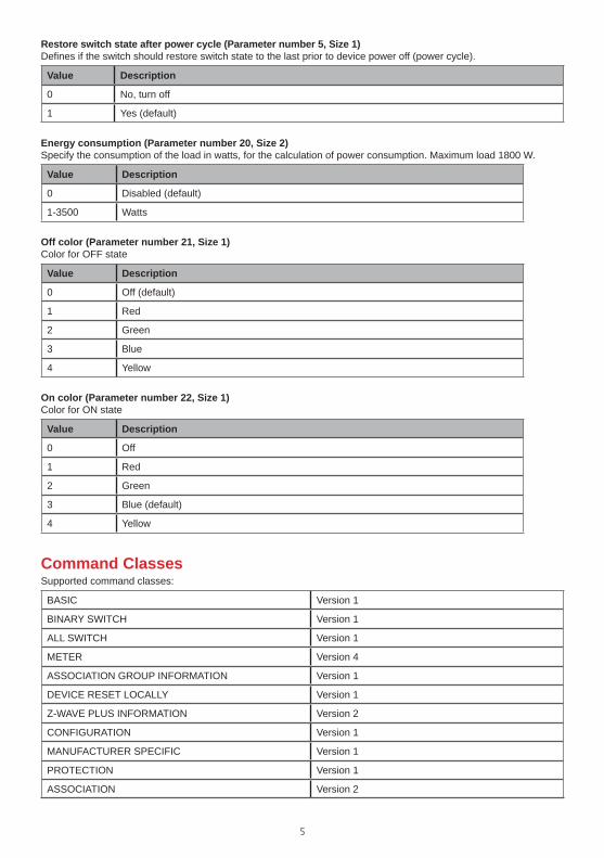
Restore switch state after power cycle (Parameter number 5, Size 1)Defines if the switch should restore switch state to the last prior to device power off (power cycle).
Value Description
0 No, turn off
1 Yes (default)
Energy consumption (Parameter number 20, Size 2)Specify the consumption of the load in watts, for the calculation of power consumption. Maximum load 1800 W.
Value Description
0 Disabled (default)
1-3500 Watts
Off color (Parameter number 21, Size 1)Color for OFF state
Value Description
0 Off (default)
1 Red
2 Green
3 Blue
4 Yellow
On color (Parameter number 22, Size 1)Color for ON state
Value Description
0 Off
1 Red
2 Green
3 Blue (default)
4 Yellow
Command ClassesSupported command classes:
BASIC Version 1
BINARY SWITCH Version 1
ALL SWITCH Version 1
METER Version 4
ASSOCIATION GROUP INFORMATION Version 1
DEVICE RESET LOCALLY Version 1
Z-WAVE PLUS INFORMATION Version 2
CONFIGURATION Version 1
MANUFACTURER SPECIFIC Version 1
PROTECTION Version 1
ASSOCIATION Version 2
5
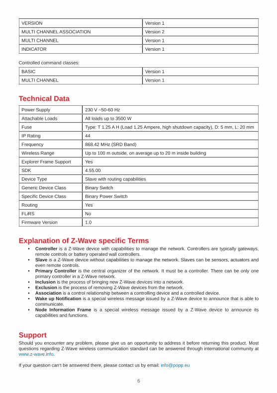
VERSION Version 1
MULTI CHANNEL ASSOCIATION Version 2
MULTI CHANNEL Version 1
INDICATOR Version 1
Controlled command classes:
BASIC Version 1
MULTI CHANNEL Version 1
Technical DataPower Supply 230 V ~50-60 Hz
Attachable Loads All loads up to 3500 W
Fuse Type: T 1.25 A H (Load 1.25 Ampere, high shutdown capacity), D: 5 mm, L: 20 mm
IP Rating 44
Frequency 868.42 MHz (SRD Band)
Wireless Range Up to 100 m outside, on average up to 20 m inside building
Explorer Frame Support Yes
SDK 4.55.00
Device Type Slave with routing capabilities
Generic Device Class Binary Switch
Specific Device Class Binary Power Switch
Routing Yes
FLiRS No
Firmware Version 1.0
Explanation of Z-Wave specific Terms• Controller is a Z-Wave device with capabilities to manage the network. Controllers are typically gateways,
remote controls or battery operated wall controllers.• Slave is a Z-Wave device without capabilities to manage the network. Slaves can be sensors, actuators and
even remote controls.• Primary Controller is the central organizer of the network. It must be a controller. There can be only one
primary controller in a Z-Wave network.• Inclusion is the process of bringing new Z-Wave devices into a network.• Exclusion is the process of removing Z-Wave devices from the network.• Association is a control relationship between a controlling device and a controlled device.• Wake up Notification is a special wireless message issued by a Z-Wave device to announce that is able to
communicate.• Node Information Frame is a special wireless message issued by a Z-Wave device to announce its
capabilities and functions.
SupportShould you encounter any problem, please give us an opportunity to address it before returning this product. Most questions regarding Z-Wave wireless communication standard can be answered through international community at www.z-wave.info.
If your question can‘t be answered there, please contact us by email: [email protected]
6

7

© 2015 POPP & Co.
While the information in this manual has been compiled with great care, it may not be deemed an assurance of product characteristics. Popp & Co. shall be liable onlyto the degree specified in the terms of sale and delivery.
The reproduction and distribution of the documentation and software supplied with this product and the use of its contents is subject to written authorization from Popp & Co. We reserve the right to make any alterations that arise as the result of technical development.
Phone: +44 (0) 20 7419 5726eMail: [email protected]: www.popp.eu


