Pagina 1 di 10 Technical leaflet Cim 747
Revisione 0 Emissione 01/2011
TECHNICAL INFORMATION
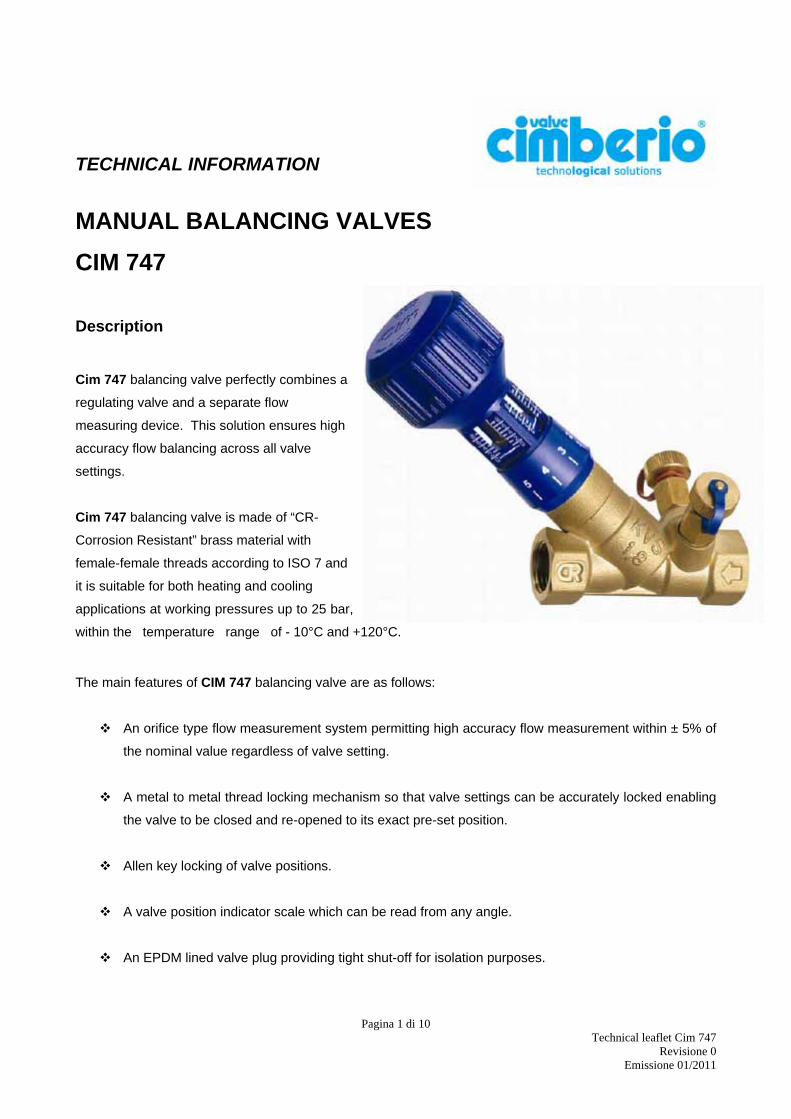
MANUAL BALANCING VALVES CIM 747 Description Cim 747 balancing valve perfectly combines a
regulating valve and a separate flow
measuring device. This solution ensures high
accuracy flow balancing across all valve
settings.
Cim 747 balancing valve is made of “CR-
Corrosion Resistant” brass material with
female-female threads according to ISO 7 and
it is suitable for both heating and cooling
applications at working pressures up to 25 bar,
within the temperature range of - 10°C and +120°C.
The main features of CIM 747 balancing valve are as follows:
An orifice type flow measurement system permitting high accuracy flow measurement within ± 5% of
the nominal value regardless of valve setting.
A metal to metal thread locking mechanism so that valve settings can be accurately locked enabling
the valve to be closed and re-opened to its exact pre-set position.
Allen key locking of valve positions.
A valve position indicator scale which can be read from any angle.
An EPDM lined valve plug providing tight shut-off for isolation purposes.
Pagina 2 di 10 Technical leaflet Cim 747
Revisione 0 Emissione 01/2011
Installation procedure Before installation of CIM 747, check that inside the valve and the pipes there is no foreign matters which
might damage the tightness of the valve.
When installing the valve, please make sure to have a pipe length 5 times the DN upstream the valve and 2
times the DN downstream, and pay attention to the arrow direction casted on the valve body, which shall be
the same as the flow one.
Burr pipe connections after having threaded them and distribute the sealing material on pipe threads only
and not on valve threads.
For assembly purposes, use a spanner, not a pipe wrench, by applying necessary working torque only on
the valve end nearest the pipe. This helps get a firmer grip and avoids potential damages to valve body.
Make sure that pipe threading length is not longer than valve threads.
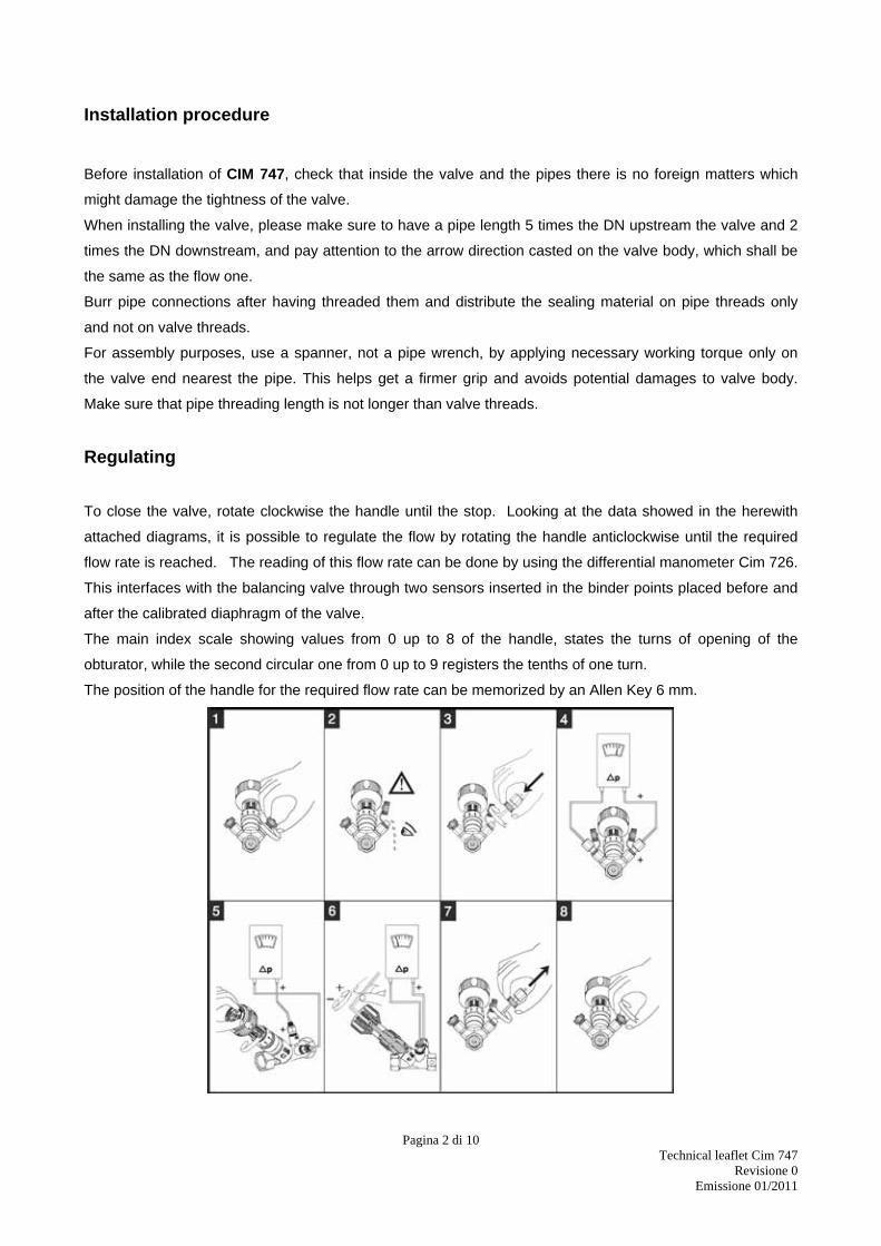
Regulating
To close the valve, rotate clockwise the handle until the stop. Looking at the data showed in the herewith
attached diagrams, it is possible to regulate the flow by rotating the handle anticlockwise until the required
flow rate is reached. The reading of this flow rate can be done by using the differential manometer Cim 726.
This interfaces with the balancing valve through two sensors inserted in the binder points placed before and
after the calibrated diaphragm of the valve.
The main index scale showing values from 0 up to 8 of the handle, states the turns of opening of the
obturator, while the second circular one from 0 up to 9 registers the tenths of one turn.
The position of the handle for the required flow rate can be memorized by an Allen Key 6 mm.
Pagina 3 di 10 Technical leaflet Cim 747
Revisione 0 Emissione 01/2011
Maintenance As a rule, the balancing valve does not need any maintenance. In case of replacement or need of
disassembling of some components of the valve, make sure that the installation is not under service or
pressure.
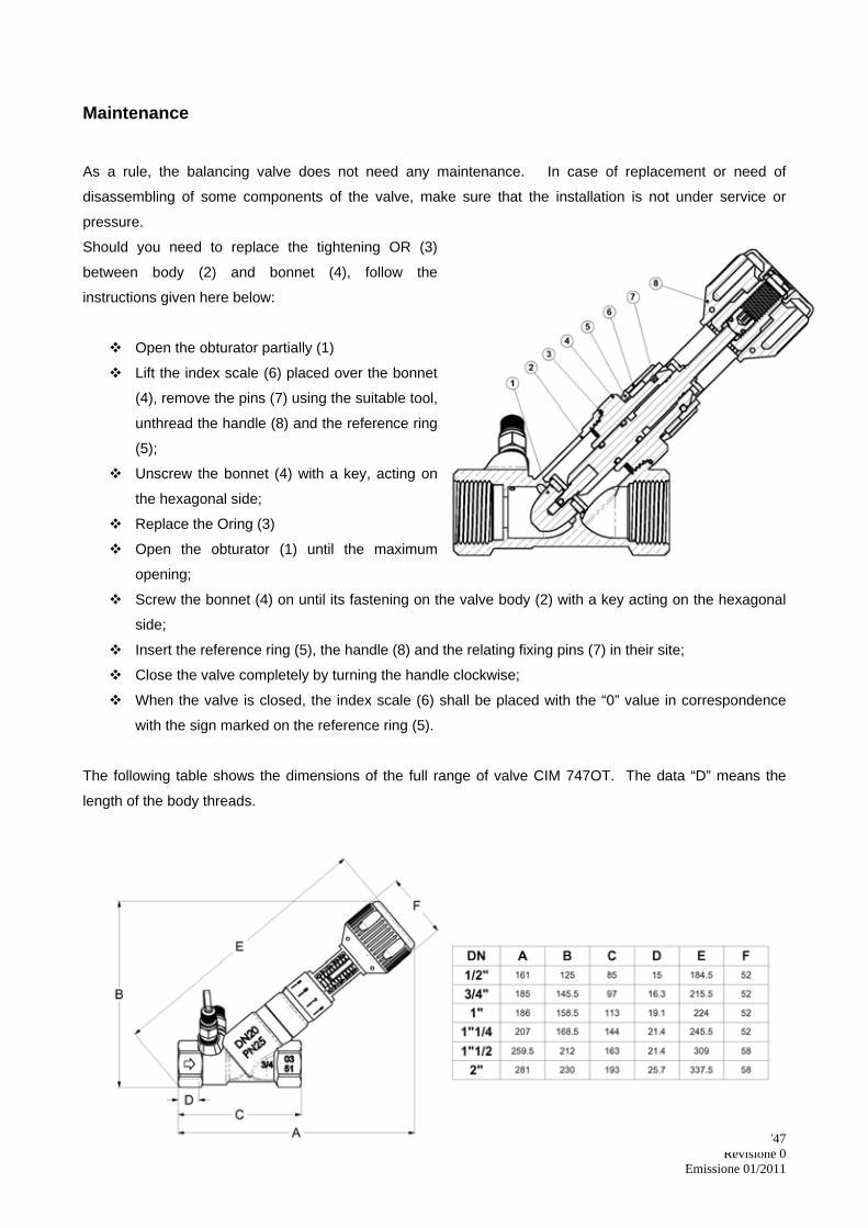
Should you need to replace the tightening OR (3)
between body (2) and bonnet (4), follow the
instructions given here below:
Open the obturator partially (1)
Lift the index scale (6) placed over the bonnet
(4), remove the pins (7) using the suitable tool,
unthread the handle (8) and the reference ring
(5);
Unscrew the bonnet (4) with a key, acting on
the hexagonal side;
Replace the Oring (3)
Open the obturator (1) until the maximum
opening;
Screw the bonnet (4) on until its fastening on the valve body (2) with a key acting on the hexagonal
side;
Insert the reference ring (5), the handle (8) and the relating fixing pins (7) in their site;
Close the valve completely by turning the handle clockwise;
When the valve is closed, the index scale (6) shall be placed with the “0” value in correspondence
with the sign marked on the reference ring (5).
The following table shows the dimensions of the full range of valve CIM 747OT. The data “D” means the
length of the body threads.
Pagina 4 di 10 Technical leaflet Cim 747
Revisione 0 Emissione 01/2011
Diagrams and tables
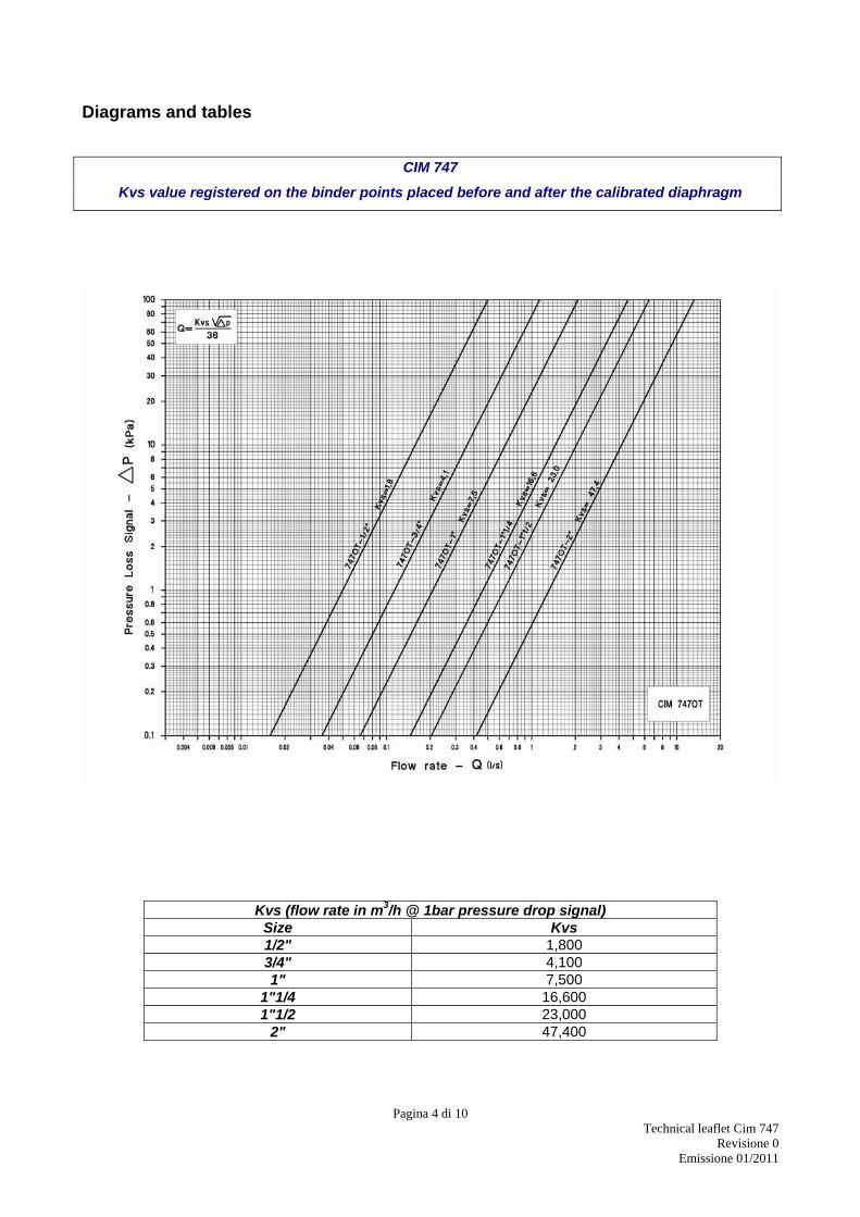
CIM 747
Kvs value registered on the binder points placed before and after the calibrated diaphragm
Kvs (flow rate in m3/h @ 1bar pressure drop signal) Size Kvs 1/2" 1,800 3/4" 4,100 1" 7,500
1"1/4 16,600 1"1/2 23,000
2" 47,400
Pagina 5 di 10 Technical leaflet Cim 747
Revisione 0 Emissione 01/2011
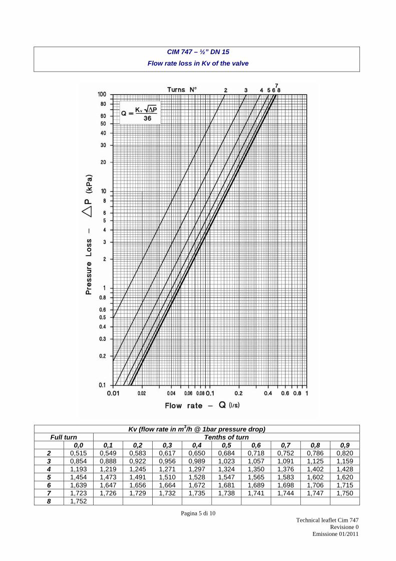
CIM 747 – ½” DN 15
Flow rate loss in Kv of the valve
Kv (flow rate in m3/h @ 1bar pressure drop) Full turn Tenths of turn 0,0 0,1 0,2 0,3 0,4 0,5 0,6 0,7 0,8 0,9
2 0,515 0,549 0,583 0,617 0,650 0,684 0,718 0,752 0,786 0,820 3 0,854 0,888 0,922 0,956 0,989 1,023 1,057 1,091 1,125 1,159 4 1,193 1,219 1,245 1,271 1,297 1,324 1,350 1,376 1,402 1,428 5 1,454 1,473 1,491 1,510 1,528 1,547 1,565 1,583 1,602 1,620 6 1,639 1,647 1,656 1,664 1,672 1,681 1,689 1,698 1,706 1,715 7 1,723 1,726 1,729 1,732 1,735 1,738 1,741 1,744 1,747 1,750 8 1,752
Pagina 6 di 10 Technical leaflet Cim 747
Revisione 0 Emissione 01/2011
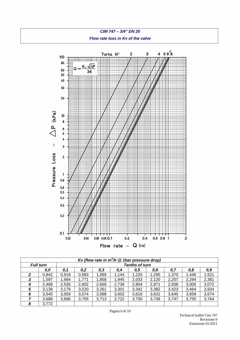
CIM 747 – 3/4” DN 20
Flow rate loss in Kv of the valve
Kv (flow rate in m3/h @ 1bar pressure drop) Full turn Tenths of turn 0,0 0,1 0,2 0,3 0,4 0,5 0,6 0,7 0,8 0,9
2 0,842 0,918 0,993 1,069 1,144 1,220 1,295 1,370 1,446 1,521 3 1,597 1,684 1,771 1,858 1,945 2,033 2,120 2,207 2,294 2,381 4 2,468 2,535 2,602 2,669 2,736 2,804 2,871 2,938 3,005 3,072 5 3,139 3,179 3,220 3,261 3,301 3,342 3,382 3,423 3,464 3,504 6 3,545 3,559 3,574 3,588 3,602 3,616 3,631 3,645 3,659 3,674 7 3,688 3,696 3,705 3,713 3,722 3,730 3,738 3,747 3,755 3,764 8 3,772
Pagina 7 di 10 Technical leaflet Cim 747
Revisione 0 Emissione 01/2011
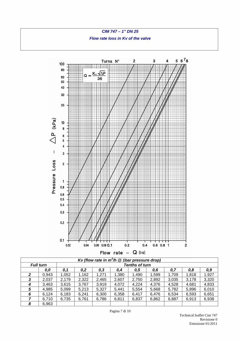
CIM 747 – 1” DN 25 Flow rate loss in Kv of the valve
Kv (flow rate in m3/h @ 1bar pressure drop) Full turn Tenths of turn 0,0 0,1 0,2 0,3 0,4 0,5 0,6 0,7 0,8 0,9
2 0,943 1,052 1,162 1,271 1,380 1,490 1,599 1,709 1,818 1,927 3 2,037 2,179 2,322 2,465 2,607 2,750 2,892 3,035 3,178 3,320 4 3,463 3,615 3,767 3,919 4,072 4,224 4,376 4,528 4,681 4,833 5 4,985 5,099 5,213 5,327 5,441 5,554 5,668 5,782 5,896 6,010 6 6,124 6,183 6,241 6,300 6,358 6,417 6,476 6,534 6,593 6,651 7 6,710 6,735 6,761 6,786 6,811 6,837 6,862 6,887 6,913 6,938 8 6,963
Pagina 8 di 10 Technical leaflet Cim 747
Revisione 0 Emissione 01/2011
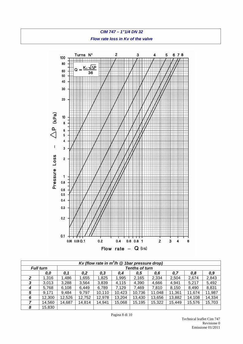
CIM 747 – 1”1/4 DN 32
Flow rate loss in Kv of the valve
Kv (flow rate in m3/h @ 1bar pressure drop) Full turn Tenths of turn 0,0 0,1 0,2 0,3 0,4 0,5 0,6 0,7 0,8 0,9
2 1,316 1,486 1,655 1,825 1,995 2,165 2,334 2,504 2,674 2,843 3 3,013 3,288 3,564 3,839 4,115 4,390 4,666 4,941 5,217 5,492 4 5,768 6,108 6,449 6,789 7,129 7,469 7,810 8,150 8,490 8,831 5 9,171 9,484 9,797 10,110 10,423 10,736 11,048 11,361 11,674 11,987 6 12,300 12,526 12,752 12,978 13,204 13,430 13,656 13,882 14,108 14,334 7 14,560 14,687 14,814 14,941 15,068 15,195 15,322 15,449 15,576 15,703 8 15,830
Pagina 9 di 10 Technical leaflet Cim 747
Revisione 0 Emissione 01/2011
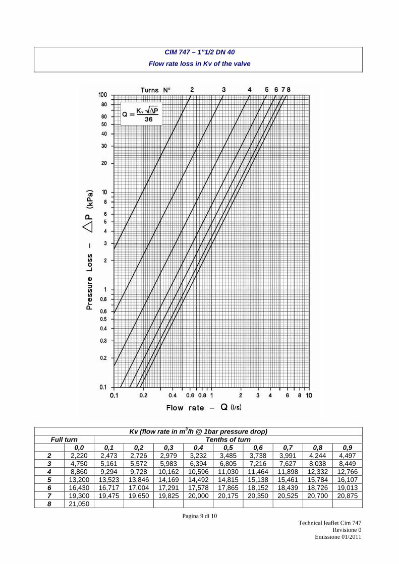
CIM 747 – 1”1/2 DN 40
Flow rate loss in Kv of the valve
Kv (flow rate in m3/h @ 1bar pressure drop) Full turn Tenths of turn 0,0 0,1 0,2 0,3 0,4 0,5 0,6 0,7 0,8 0,9
2 2,220 2,473 2,726 2,979 3,232 3,485 3,738 3,991 4,244 4,497 3 4,750 5,161 5,572 5,983 6,394 6,805 7,216 7,627 8,038 8,449 4 8,860 9,294 9,728 10,162 10,596 11,030 11,464 11,898 12,332 12,766 5 13,200 13,523 13,846 14,169 14,492 14,815 15,138 15,461 15,784 16,107 6 16,430 16,717 17,004 17,291 17,578 17,865 18,152 18,439 18,726 19,013 7 19,300 19,475 19,650 19,825 20,000 20,175 20,350 20,525 20,700 20,875 8 21,050
Pagina 10 di 10 Technical leaflet Cim 747
Revisione 0 Emissione 01/2011
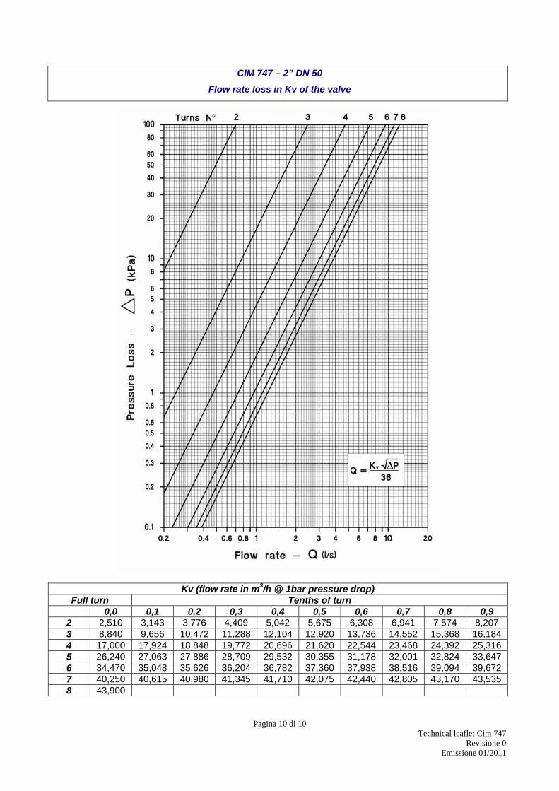
CIM 747 – 2” DN 50
Flow rate loss in Kv of the valve
Kv (flow rate in m3/h @ 1bar pressure drop) Full turn Tenths of turn 0,0 0,1 0,2 0,3 0,4 0,5 0,6 0,7 0,8 0,9
2 2,510 3,143 3,776 4,409 5,042 5,675 6,308 6,941 7,574 8,207 3 8,840 9,656 10,472 11,288 12,104 12,920 13,736 14,552 15,368 16,184 4 17,000 17,924 18,848 19,772 20,696 21,620 22,544 23,468 24,392 25,316 5 26,240 27,063 27,886 28,709 29,532 30,355 31,178 32,001 32,824 33,647 6 34,470 35,048 35,626 36,204 36,782 37,360 37,938 38,516 39,094 39,672 7 40,250 40,615 40,980 41,345 41,710 42,075 42,440 42,805 43,170 43,535 8 43,900


