Machine Automation Controller
NX-series
NX102 CPU Unit
CPU Unit
Hardware User’s Manual
W593-E1-01
NX102-
• Sysmac and SYSMAC are trademarks or registered trademarks of OMRON Corporation in Japan and other countries for OMRON factory automation products.
• Microsoft, Windows, Windows Vista, Excel, and Visual Basic are either registered trademarks or trademarks of Microsoft Corporation in the United States and other countries.
• EtherCAT® is registered trademark and patented technology, licensed by Beckhoff Automation GmbH, Germany.
• ODVA, CIP, CompoNet, DeviceNet, and EtherNet/IP are trademarks of ODVA.
• The SD and SDHC logos are trademarks of SD-3C, LLC.
Other company names and product names in this document are the trademarks or registered trademarks of their respective companies.
Trademarks
Copyrights
NOTE• All rights reserved. No part of this publication may be reproduced, stored in a retrieval system, or transmitted, in
any form, or by any means, mechanical, electronic, photocopying, recording, or otherwise, without the prior written permission of OMRON.
• No patent liability is assumed with respect to the use of the information contained herein.Moreover, because OMRON is constantly striving to improve its high-quality products, the information contained in this manual is subject to change without notice.
• Every precaution has been taken in the preparation of this manual. Nevertheless, OMRON assumes no responsi-bility for errors or omissions.Neither is any liability assumed for damages resulting from the use of the information contained in this publication.
• Microsoft product screen shots reprinted with permission from Microsoft Corporation.• This product incorporates certain third party software. The license and copyright information associated with this
software is available at http://www.fa.omron.co.jp/nj_info_e/.
IntroductionThank you for purchasing an NX-series CPU Unit.This manual contains information that is necessary to use the NX-series CPU Unit. Please read thismanual and make sure you understand the functionality and performance of the NX-series CPU Unitbefore you attempt to use it in a control system.Keep this manual in a safe place where it will be available for reference during operation.
Intended AudienceThis manual is intended for the following personnel, who must also have knowledge of electrical sys-tems (an electrical engineer or the equivalent).• Personnel in charge of introducing FA systems.• Personnel in charge of designing FA systems.• Personnel in charge of installing and maintaining FA systems.• Personnel in charge of managing FA systems and facilities.For programming, this manual is intended for personnel who understand the programming languagespecifications in international standard IEC 61131-3 or Japanese standard JIS B 3503.
Applicable ProductsThis manual covers the following products.• NX-series CPU Units
NX102-££££
Part of the specifications and restrictions for the CPU Units are given in other manuals. Refer to Rele-vant Manuals on page 7 and Related Manuals on page 38.
Introduction
1NX-series NX102 CPU Unit Hardware User’s Manual (W593)

Introduction
2 NX-series NX102 CPU Unit Hardware User’s Manual (W593)
CONTENTSIntroduction .............................................................................................................. 1
Intended Audience...........................................................................................................................................1Applicable Products .........................................................................................................................................1
Relevant Manuals..................................................................................................... 7
Manual Structure...................................................................................................... 9Page Structure.................................................................................................................................................9Special Information ........................................................................................................................................10Precaution on Terminology ............................................................................................................................10
Terms and Conditions Agreement........................................................................ 11Warranty, Limitations of Liability .................................................................................................................... 11Application Considerations ............................................................................................................................12Disclaimers ....................................................................................................................................................12
Safety Precautions................................................................................................. 14Definition of Precautionary Information..........................................................................................................14Symbols .........................................................................................................................................................14WARNING......................................................................................................................................................15Cautions.........................................................................................................................................................17
Precautions for Safe Use ...................................................................................... 18
Precautions for Correct Use ................................................................................. 29
Regulations and Standards .................................................................................. 33Conformance to EU Directives ......................................................................................................................33Conformance to UL and CSA Standards.......................................................................................................34Conformance to KC Standards......................................................................................................................34Software Licenses and Copyrights ................................................................................................................34
Versions .................................................................................................................. 35Checking Versions .........................................................................................................................................35Unit Versions of CPU Units and Sysmac Studio Versions .............................................................................37
Related Manuals..................................................................................................... 38
Terminology............................................................................................................ 41
Revision History..................................................................................................... 46
Sections in this Manual ......................................................................................... 47
Section 1 Introduction to NX-series Controllers1-1 The NX-series Controller.....................................................................................................1 - 2
1-1-1 Features ....................................................................................................................................1 - 31-1-2 Introduction to the System Configurations ................................................................................1 - 6
1-2 Specifications.......................................................................................................................1 - 91-3 Overall Operating Procedure for the CPU Unit ...............................................................1 - 14
1-3-1 Overall Procedure ...................................................................................................................1 - 14
CONTENTS
3NX-series NX102 CPU Unit Hardware User’s Manual (W593)
1-3-2 Procedure Details....................................................................................................................1 - 15
Section 2 System Configuration2-1 Basic System Configuration ...............................................................................................2 - 2
2-1-1 EtherCAT Network Configuration ..............................................................................................2 - 32-1-2 NX Unit Configuration ...............................................................................................................2 - 4
2-2 Connecting to the Sysmac Studio......................................................................................2 - 62-3 Network Configuration ........................................................................................................2 - 7
Section 3 Configuration Units3-1 CPU Units .............................................................................................................................3 - 2
3-1-1 Models and Specifications ........................................................................................................3 - 23-1-2 Part Names and Functions........................................................................................................3 - 43-1-3 Operation Status Indicators.......................................................................................................3 - 63-1-4 Terminal Blocks .......................................................................................................................3 - 103-1-5 Battery.....................................................................................................................................3 - 113-1-6 ID Information Indication .........................................................................................................3 - 12
3-2 SD Memory Cards ..............................................................................................................3 - 143-2-1 Models and Specifications ......................................................................................................3 - 143-2-2 Purpose...................................................................................................................................3 - 14
3-3 Power Supply-related Units ..............................................................................................3 - 153-4 NX Units ..............................................................................................................................3 - 163-5 Sysmac Studio ...................................................................................................................3 - 17
3-5-1 Model Numbers.......................................................................................................................3 - 173-5-2 Connection ..............................................................................................................................3 - 17
Section 4 Designing the Power Supply System4-1 Power Supply System and Design Concepts....................................................................4 - 2
4-1-1 Power Supply System and Types of Power Supplies ...............................................................4 - 24-1-2 NX-series Power Supply-related Units ......................................................................................4 - 44-1-3 Design Concepts for Power Supply to the CPU Rack...............................................................4 - 6
4-2 Designing the NX Unit Power Supply System...................................................................4 - 74-2-1 Procedure for Designing the NX Unit Power Supply System....................................................4 - 74-2-2 Calculation Example for the NX Unit Power Supply..................................................................4 - 8
4-3 Designing the I/O Power Supply System.........................................................................4 - 104-3-1 I/O Power Supply Method .......................................................................................................4 - 104-3-2 Designing the I/O Power Supply from the NX Bus..................................................................4 - 114-3-3 Designing the I/O Power Supply from External Sources.........................................................4 - 164-3-4 Restrictions on Inrush Current for ON/OFF Operation............................................................4 - 17
4-4 Selecting External Power Supplies and Protective Devices..........................................4 - 184-4-1 Selecting the Unit Power Supply.............................................................................................4 - 184-4-2 Selecting the I/O Power Supplies............................................................................................4 - 204-4-3 Selecting Protective Devices...................................................................................................4 - 21
Section 5 Installation and Wiring5-1 Processing at Power ON and Power OFF..........................................................................5 - 2
5-1-1 Power ON Operation.................................................................................................................5 - 25-1-2 Power OFF Operation ...............................................................................................................5 - 45-1-3 Resetting the Controller from the Sysmac Studio .....................................................................5 - 6
CONTENTS
4 NX-series NX102 CPU Unit Hardware User’s Manual (W593)
5-2 Fail-safe Circuits ..................................................................................................................5 - 75-3 Mounting Units.....................................................................................................................5 - 9
5-3-1 Installation in a Control Panel .................................................................................................5 - 105-3-2 Preparations for Installation ....................................................................................................5 - 145-3-3 Installing the CPU Unit ............................................................................................................5 - 165-3-4 Installing and Connecting NX Units.........................................................................................5 - 185-3-5 Mounting the End Cover .........................................................................................................5 - 225-3-6 Mounting the End Plates .........................................................................................................5 - 235-3-7 Attaching Markers ...................................................................................................................5 - 255-3-8 Installing and Removing the SD Memory Card .......................................................................5 - 265-3-9 Battery Installation...................................................................................................................5 - 305-3-10 Removing CPU Unit ................................................................................................................5 - 335-3-11 Removing NX Units .................................................................................................................5 - 345-3-12 Assembled Appearance and Dimensions ...............................................................................5 - 35
5-4 Wiring..................................................................................................................................5 - 385-4-1 Wiring the Unit Power Supply .................................................................................................5 - 395-4-2 Wiring the Additional NX Unit Power Supply Unit ...................................................................5 - 395-4-3 Wiring the Additional I/O Power Supply Unit ...........................................................................5 - 395-4-4 Wiring the Protective Devices .................................................................................................5 - 405-4-5 Grounding ...............................................................................................................................5 - 415-4-6 Wiring the Built-in EtherCAT Port ............................................................................................5 - 465-4-7 Wiring the Built-in EtherNet/IP Port .........................................................................................5 - 465-4-8 Wiring to the CPU Unit Terminal Block....................................................................................5 - 46
5-5 Control Panel Installation..................................................................................................5 - 625-5-1 Temperature ............................................................................................................................5 - 625-5-2 Humidity ..................................................................................................................................5 - 645-5-3 Vibration and Shock ................................................................................................................5 - 645-5-4 Atmosphere.............................................................................................................................5 - 645-5-5 Electrical Environment ............................................................................................................5 - 655-5-6 Grounding ...............................................................................................................................5 - 69
Section 6 Troubleshooting6-1 Overview of Troubleshooting .............................................................................................6 - 2
Section 7 Inspection and Maintenance7-1 Cleaning and Maintenance..................................................................................................7 - 2
7-1-1 Cleaning ....................................................................................................................................7 - 27-1-2 Periodic Inspections ..................................................................................................................7 - 37-1-3 Unit Replacement Precautions..................................................................................................7 - 4
7-2 Replacing the Battery ..........................................................................................................7 - 6
AppendicesA-1 Specifications...................................................................................................................... A - 2A-2 Dimensions.......................................................................................................................... A - 3
A-2-1 NX-series NX102 CPU Unit ..................................................................................................... A - 3A-2-2 End Cover ................................................................................................................................ A - 3A-2-3 SD Memory Card ..................................................................................................................... A - 4
A-3 List of Terminal Block Models ........................................................................................... A - 5A-3-1 Model Notation ......................................................................................................................... A - 5A-3-2 List of Terminal Block Models................................................................................................... A - 5
A-4 Version Information ............................................................................................................ A - 7A-4-1 Relationship between Unit Versions of CPU Units and Sysmac Studio Versions .................... A - 7A-4-2 Functions That Were Added or Changed for Each Unit Version .............................................. A - 7
CONTENTS
5NX-series NX102 CPU Unit Hardware User’s Manual (W593)

A-5 Support Functions of the CPU Units and Restrictions on the CPU Unit ....................... A - 8
Index
CONTENTS
6 NX-series NX102 CPU Unit Hardware User’s Manual (W593)
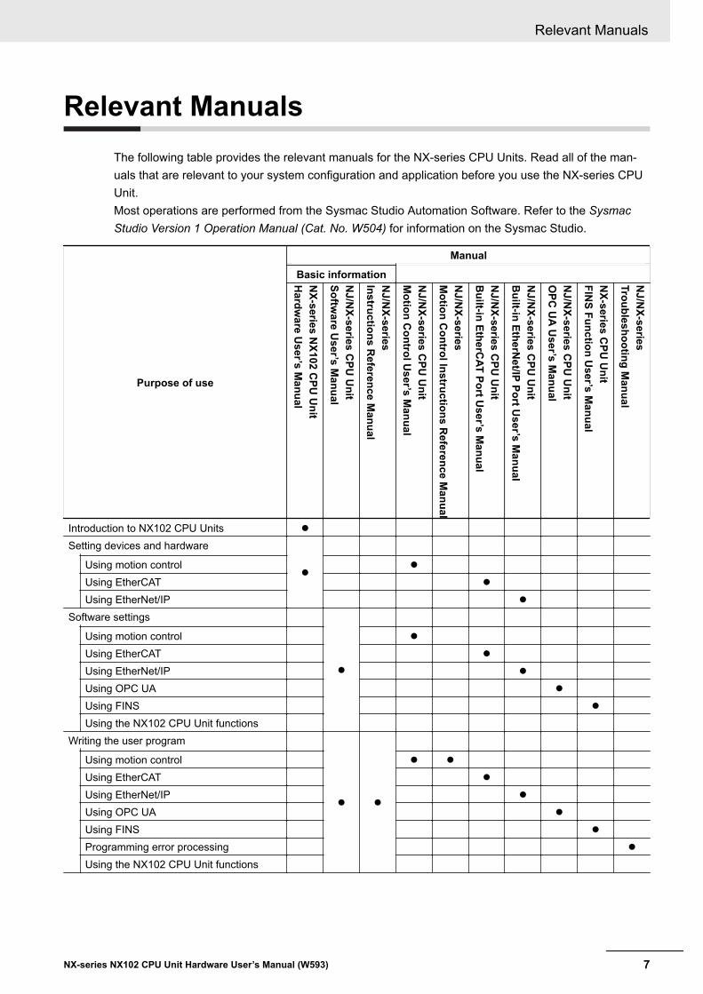
Relevant ManualsThe following table provides the relevant manuals for the NX-series CPU Units. Read all of the man-uals that are relevant to your system configuration and application before you use the NX-series CPUUnit.Most operations are performed from the Sysmac Studio Automation Software. Refer to the SysmacStudio Version 1 Operation Manual (Cat. No. W504) for information on the Sysmac Studio.
Purpose of use
Manual
Basic informationNX-series N
X102 CPU
Unit
Hardw
are User’s M
anual
NJ/N
X-series CPU
Unit
Software U
ser’s Manual
NJ/N
X-seriesInstructions R
eference Manual
NJ/N
X-series CPU
Unit
Motion C
ontrol User’s M
anual
NJ/N
X-seriesM
otion Control Instructions R
eference Manual
NJ/N
X-series CPU
Unit
Built-in EtherC
AT Port User’s M
anual
NJ/N
X-series CPU
Unit
Built-in EtherN
et/IP Port User’s M
anual
NJ/N
X-series CPU
Unit
OPC
UA
User’s M
anual
NX-series C
PU U
nitFIN
S Function User’s M
anual
NJ/N
X-seriesTroubleshooting M
anual
Introduction to NX102 CPU Units l
Setting devices and hardware
lUsing motion control l
Using EtherCAT l
Using EtherNet/IP l
Software settings
l
Using motion control l
Using EtherCAT l
Using EtherNet/IP l
Using OPC UA l
Using FINS l
Using the NX102 CPU Unit functionsWriting the user program
l l
Using motion control l l
Using EtherCAT l
Using EtherNet/IP l
Using OPC UA l
Using FINS l
Programming error processing l
Using the NX102 CPU Unit functions
Relevant Manuals
7NX-series NX102 CPU Unit Hardware User’s Manual (W593)
Purpose of use
Manual
Basic informationNX-series N
X102 CPU
Unit
Hardw
are User’s M
anual
NJ/N
X-series CPU
Unit
Software U
ser’s Manual
NJ/N
X-seriesInstructions R
eference Manual
NJ/N
X-series CPU
Unit
Motion C
ontrol User’s M
anual
NJ/N
X-seriesM
otion Control Instructions R
eference Manual
NJ/N
X-series CPU
Unit
Built-in EtherC
AT Port User’s M
anual
NJ/N
X-series CPU
Unit
Built-in EtherN
et/IP Port User’s M
anual
NJ/N
X-series CPU
Unit
OPC
UA
User’s M
anual
NX-series C
PU U
nitFIN
S Function User’s M
anual
NJ/N
X-seriesTroubleshooting M
anual
Testing operation and debugging
l
Using motion control l
Using EtherCAT l
Using EtherNet/IP l
Using OPC UA l
Using FINS l
Using the NX102 CPU Unit functionsLearning about error management and cor-rections*1 r r l
Maintenance
lUsing motion control l
Using EtherCAT l
Using EtherNet/IP l
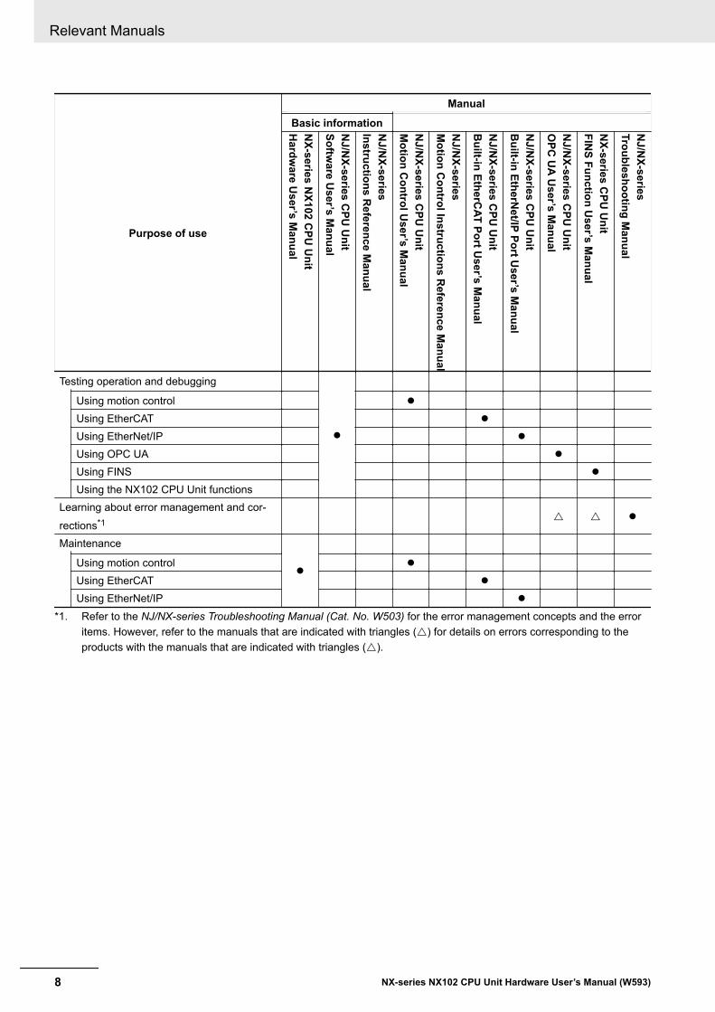
*1. Refer to the NJ/NX-series Troubleshooting Manual (Cat. No. W503) for the error management concepts and the erroritems. However, refer to the manuals that are indicated with triangles (r) for details on errors corresponding to theproducts with the manuals that are indicated with triangles (r).
Relevant Manuals
8 NX-series NX102 CPU Unit Hardware User’s Manual (W593)
Manual Structure
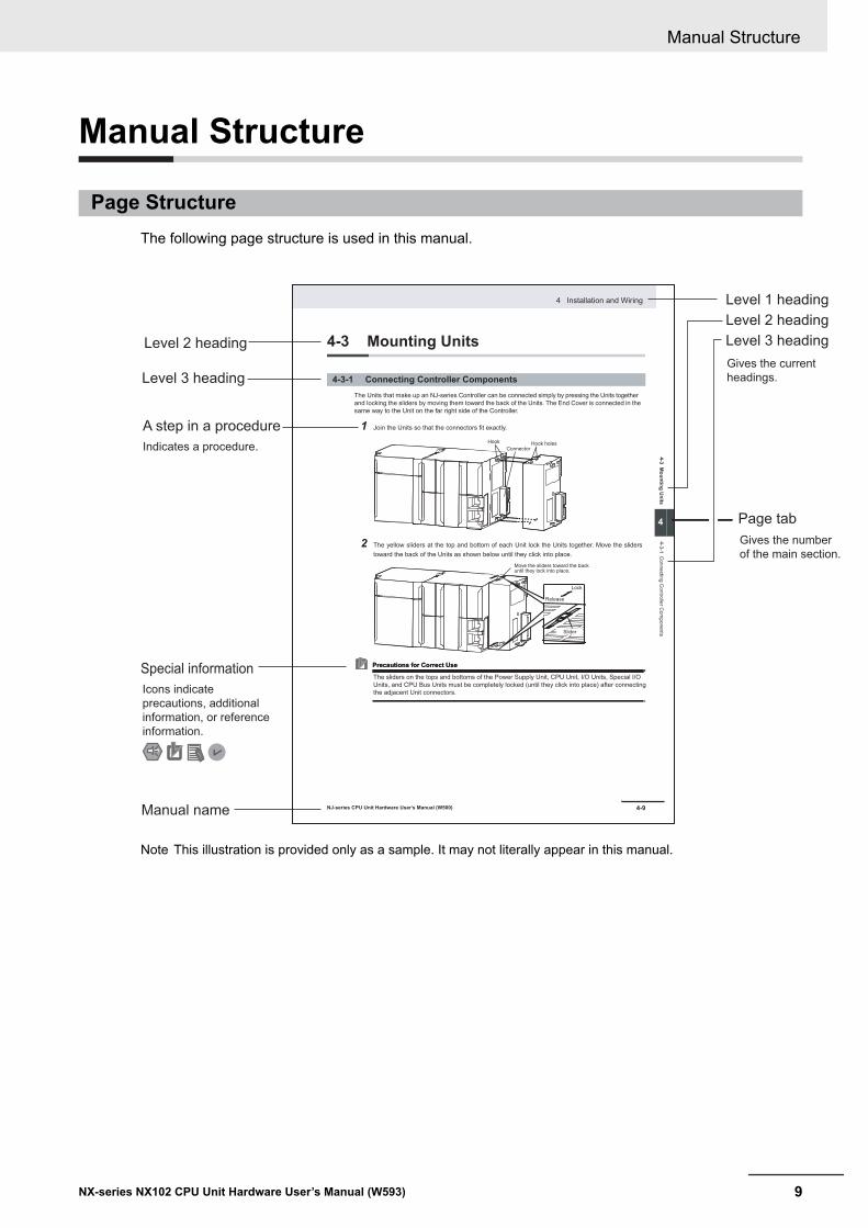
Page StructureThe following page structure is used in this manual.
4-9
4 Installation and Wiring
NJ-series CPU Unit Hardware User’s Manual (W500)
sti
nU
gni
tn
uo
M
3-4
4
s tn
en
op
mo
C r
ellor
tn
oC
gni
tc
en
no
C
1-3-
4
4-3 Mounting Units
The Units that make up an NJ-series Controller can be connected simply by pressing the Units together
and locking the sliders by moving them toward the back of the Units. The End Cover is connected in the
same way to the Unit on the far right side of the Controller.
1 Join the Units so that the connectors fit exactly.
2 The yellow sliders at the top and bottom of each Unit lock the Units together. Move the sliders
toward the back of the Units as shown below until they click into place.
Precautions for Correct UsePrecautions for Correct Use
4-3-1 Connecting Controller Components
Connector
Hook Hook holes
Slider
Lock
Release
Move the sliders toward the back until they lock into place.
Level 1 heading
Level 2 heading
Level 3 headingLevel 2 heading
A step in a procedure
Manual name
Special information
Level 3 heading
Page tab
Gives the current
headings.
Indicates a procedure.
Icons indicate
precautions, additional
information, or reference
information.
Gives the number
of the main section.
The sliders on the tops and bottoms of the Power Supply Unit, CPU Unit, I/O Units, Special I/O
Units, and CPU Bus Units must be completely locked (until they click into place) after connecting
the adjacent Unit connectors.
Note This illustration is provided only as a sample. It may not literally appear in this manual.
Manual Structure
9NX-series NX102 CPU Unit Hardware User’s Manual (W593)
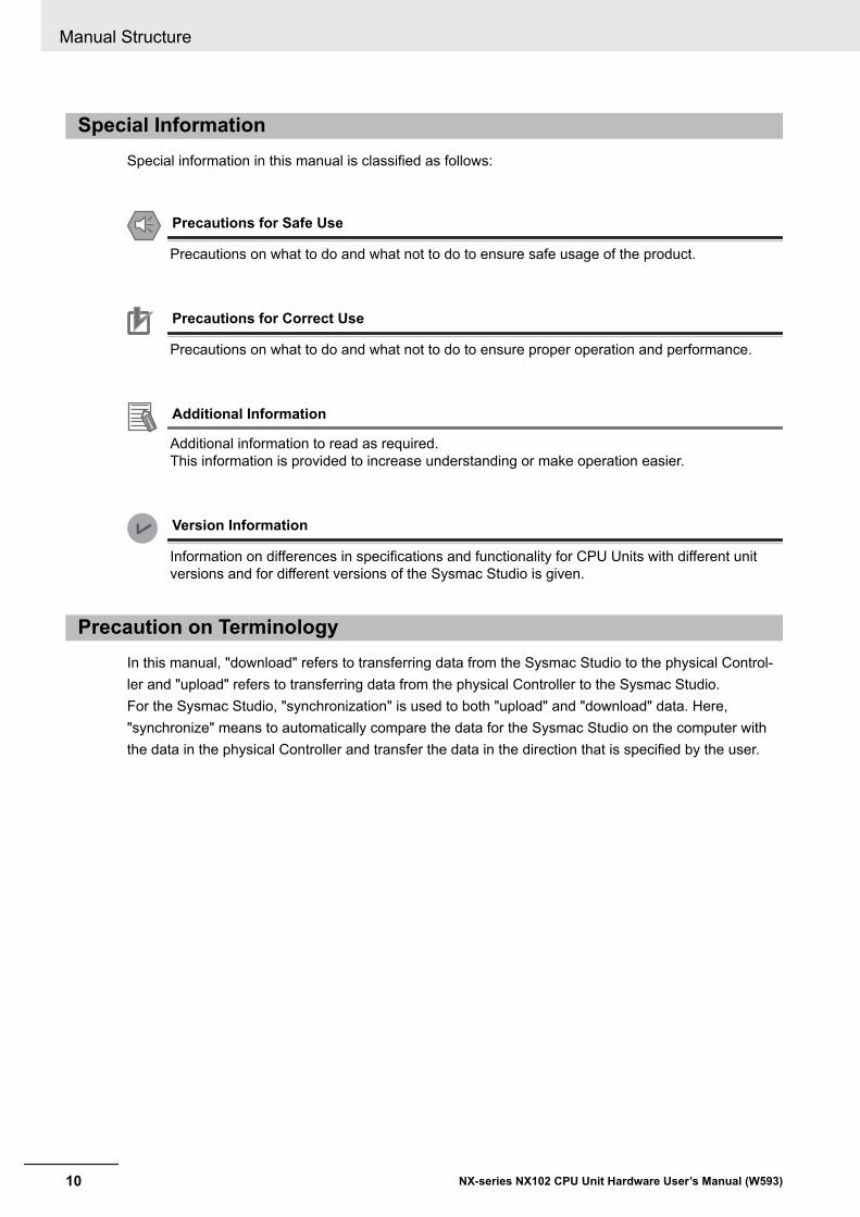
Special InformationSpecial information in this manual is classified as follows:
Precautions for Safe Use
Precautions on what to do and what not to do to ensure safe usage of the product.
Precautions for Correct Use
Precautions on what to do and what not to do to ensure proper operation and performance.
Additional Information
Additional information to read as required.This information is provided to increase understanding or make operation easier.
Version Information
Information on differences in specifications and functionality for CPU Units with different unitversions and for different versions of the Sysmac Studio is given.
Precaution on TerminologyIn this manual, "download" refers to transferring data from the Sysmac Studio to the physical Control-ler and "upload" refers to transferring data from the physical Controller to the Sysmac Studio.For the Sysmac Studio, "synchronization" is used to both "upload" and "download" data. Here,"synchronize" means to automatically compare the data for the Sysmac Studio on the computer withthe data in the physical Controller and transfer the data in the direction that is specified by the user.
Manual Structure
10 NX-series NX102 CPU Unit Hardware User’s Manual (W593)
Terms and Conditions Agreement
Warranty, Limitations of Liability
Warranties
l Exclusive WarrantyOmron’s exclusive warranty is that the Products will be free from defects in materials and work-manship for a period of twelve months from the date of sale by Omron (or such other period ex-pressed in writing by Omron). Omron disclaims all other warranties, express or implied.
l LimitationsOMRON MAKES NO WARRANTY OR REPRESENTATION, EXPRESS OR IMPLIED, ABOUTNON-INFRINGEMENT, MERCHANTABILITY OR FITNESS FOR A PARTICULAR PURPOSE OFTHE PRODUCTS. BUYER ACKNOWLEDGES THAT IT ALONE HAS DETERMINED THAT THEPRODUCTS WILL SUITABLY MEET THE REQUIREMENTS OF THEIR INTENDED USE.
Omron further disclaims all warranties and responsibility of any type for claims or expenses basedon infringement by the Products or otherwise of any intellectual property right.
l Buyer RemedyOmron’s sole obligation hereunder shall be, at Omron’s election, to (i) replace (in the form originallyshipped with Buyer responsible for labor charges for removal or replacement thereof) the non-com-plying Product, (ii) repair the non-complying Product, or (iii) repay or credit Buyer an amount equalto the purchase price of the non-complying Product; provided that in no event shall Omron be re-sponsible for warranty, repair, indemnity or any other claims or expenses regarding the Productsunless Omron’s analysis confirms that the Products were properly handled, stored, installed andmaintained and not subject to contamination, abuse, misuse or inappropriate modification. Returnof any Products by Buyer must be approved in writing by Omron before shipment. Omron Compa-nies shall not be liable for the suitability or unsuitability or the results from the use of Products incombination with any electrical or electronic components, circuits, system assemblies or any othermaterials or substances or environments. Any advice, recommendations or information given orallyor in writing, are not to be construed as an amendment or addition to the above warranty.
See http://www.omron.com/global/ or contact your Omron representative for published information.
Limitation on Liability; EtcOMRON COMPANIES SHALL NOT BE LIABLE FOR SPECIAL, INDIRECT, INCIDENTAL, OR CON-SEQUENTIAL DAMAGES, LOSS OF PROFITS OR PRODUCTION OR COMMERCIAL LOSS IN ANY
Terms and Conditions Agreement
11NX-series NX102 CPU Unit Hardware User’s Manual (W593)
WAY CONNECTED WITH THE PRODUCTS, WHETHER SUCH CLAIM IS BASED IN CONTRACT,WARRANTY, NEGLIGENCE OR STRICT LIABILITY.
Further, in no event shall liability of Omron Companies exceed the individual price of the Product onwhich liability is asserted.
Application Considerations
Suitability of UseOmron Companies shall not be responsible for conformity with any standards, codes or regulationswhich apply to the combination of the Product in the Buyer’s application or use of the Product. At Buy-er’s request, Omron will provide applicable third party certification documents identifying ratings andlimitations of use which apply to the Product. This information by itself is not sufficient for a completedetermination of the suitability of the Product in combination with the end product, machine, system, orother application or use. Buyer shall be solely responsible for determining appropriateness of the par-ticular Product with respect to Buyer’s application, product or system. Buyer shall take application re-sponsibility in all cases.
NEVER USE THE PRODUCT FOR AN APPLICATION INVOLVING SERIOUS RISK TO LIFE ORPROPERTY OR IN LARGE QUANTITIES WITHOUT ENSURING THAT THE SYSTEM AS A WHOLEHAS BEEN DESIGNED TO ADDRESS THE RISKS, AND THAT THE OMRON PRODUCT(S) ISPROPERLY RATED AND INSTALLED FOR THE INTENDED USE WITHIN THE OVERALL EQUIP-MENT OR SYSTEM.
Programmable ProductsOmron Companies shall not be responsible for the user’s programming of a programmable Product, orany consequence thereof.
Disclaimers
Performance DataData presented in Omron Company websites, catalogs and other materials is provided as a guide forthe user in determining suitability and does not constitute a warranty. It may represent the result ofOmron’s test conditions, and the user must correlate it to actual application requirements. Actual per-formance is subject to the Omron’s Warranty and Limitations of Liability.
Change in SpecificationsProduct specifications and accessories may be changed at any time based on improvements and oth-er reasons. It is our practice to change part numbers when published ratings or features are changed,or when significant construction changes are made. However, some specifications of the Product may
Terms and Conditions Agreement
12 NX-series NX102 CPU Unit Hardware User’s Manual (W593)
be changed without any notice. When in doubt, special part numbers may be assigned to fix or estab-lish key specifications for your application. Please consult with your Omron’s representative at anytime to confirm actual specifications of purchased Product.
Errors and OmissionsInformation presented by Omron Companies has been checked and is believed to be accurate; how-ever, no responsibility is assumed for clerical, typographical or proofreading errors or omissions.
Terms and Conditions Agreement
13NX-series NX102 CPU Unit Hardware User’s Manual (W593)
Safety Precautions
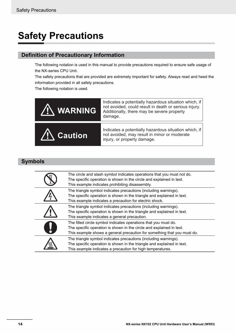
Definition of Precautionary InformationThe following notation is used in this manual to provide precautions required to ensure safe usage ofthe NX-series CPU Unit.The safety precautions that are provided are extremely important for safety. Always read and heed theinformation provided in all safety precautions.The following notation is used.
Indicates a potentially hazardous situation which, if not avoided, could result in death or serious injury. Additionally, there may be severe property damage.
Indicates a potentially hazardous situation which, if not avoided, may result in minor or moderate injury, or property damage.
WARNING
Caution
Symbols
The circle and slash symbol indicates operations that you must not do.The specific operation is shown in the circle and explained in text.This example indicates prohibiting disassembly.The triangle symbol indicates precautions (including warnings).The specific operation is shown in the triangle and explained in text.This example indicates a precaution for electric shock.The triangle symbol indicates precautions (including warnings).The specific operation is shown in the triangle and explained in text.This example indicates a general precaution.The filled circle symbol indicates operations that you must do.The specific operation is shown in the circle and explained in text.This example shows a general precaution for something that you must do.The triangle symbol indicates precautions (including warnings).The specific operation is shown in the triangle and explained in text.This example indicates a precaution for high temperatures.
Safety Precautions
14 NX-series NX102 CPU Unit Hardware User’s Manual (W593)
WARNING
WARNING
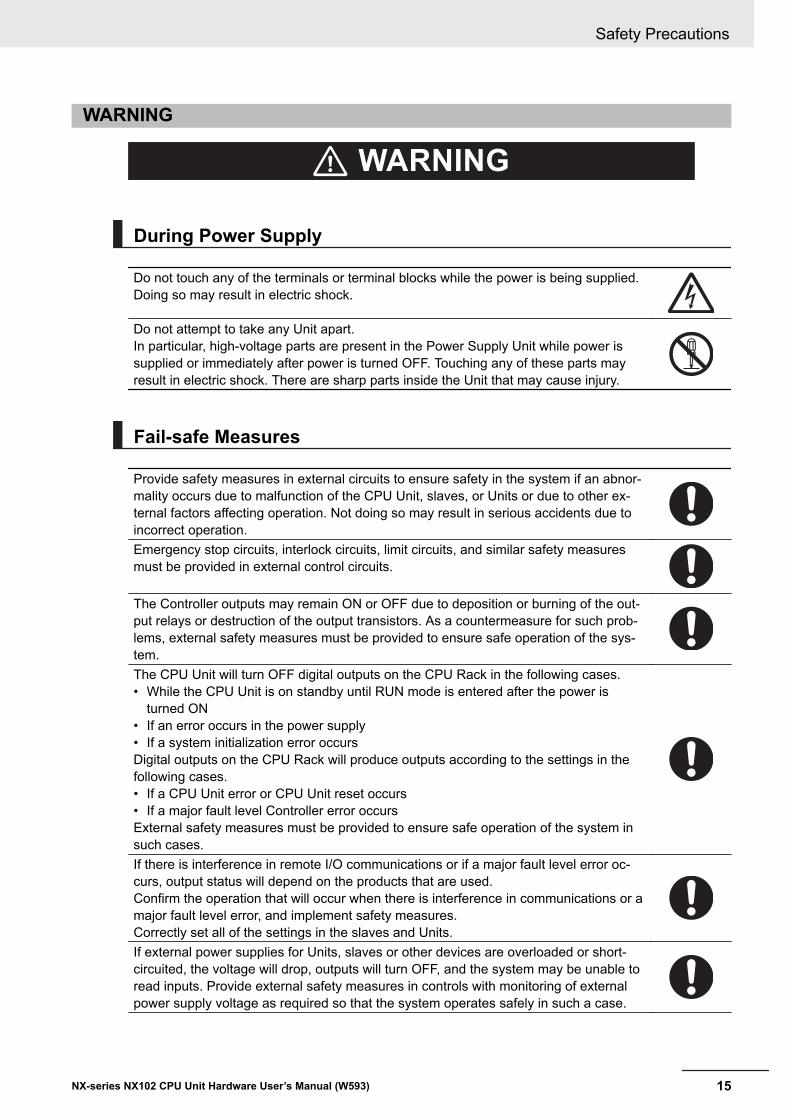
During Power Supply
Do not touch any of the terminals or terminal blocks while the power is being supplied.Doing so may result in electric shock.
Do not attempt to take any Unit apart.In particular, high-voltage parts are present in the Power Supply Unit while power issupplied or immediately after power is turned OFF. Touching any of these parts mayresult in electric shock. There are sharp parts inside the Unit that may cause injury.
Fail-safe Measures
Provide safety measures in external circuits to ensure safety in the system if an abnor-mality occurs due to malfunction of the CPU Unit, slaves, or Units or due to other ex-ternal factors affecting operation. Not doing so may result in serious accidents due toincorrect operation.Emergency stop circuits, interlock circuits, limit circuits, and similar safety measuresmust be provided in external control circuits.
The Controller outputs may remain ON or OFF due to deposition or burning of the out-put relays or destruction of the output transistors. As a countermeasure for such prob-lems, external safety measures must be provided to ensure safe operation of the sys-tem.The CPU Unit will turn OFF digital outputs on the CPU Rack in the following cases.• While the CPU Unit is on standby until RUN mode is entered after the power is
turned ON• If an error occurs in the power supply• If a system initialization error occursDigital outputs on the CPU Rack will produce outputs according to the settings in thefollowing cases.• If a CPU Unit error or CPU Unit reset occurs• If a major fault level Controller error occursExternal safety measures must be provided to ensure safe operation of the system insuch cases.If there is interference in remote I/O communications or if a major fault level error oc-curs, output status will depend on the products that are used.Confirm the operation that will occur when there is interference in communications or amajor fault level error, and implement safety measures.Correctly set all of the settings in the slaves and Units.If external power supplies for Units, slaves or other devices are overloaded or short-circuited, the voltage will drop, outputs will turn OFF, and the system may be unable toread inputs. Provide external safety measures in controls with monitoring of externalpower supply voltage as required so that the system operates safely in such a case.
Safety Precautions
15NX-series NX102 CPU Unit Hardware User’s Manual (W593)
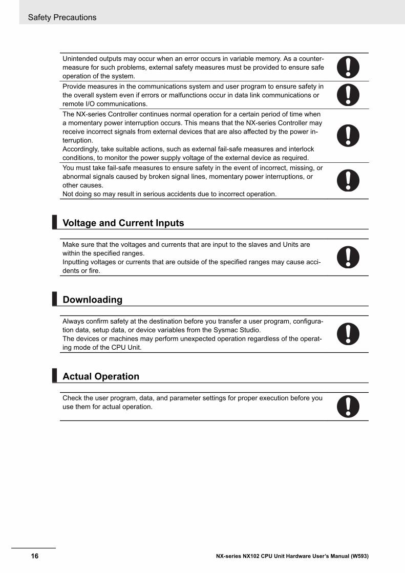
Unintended outputs may occur when an error occurs in variable memory. As a counter-measure for such problems, external safety measures must be provided to ensure safeoperation of the system.Provide measures in the communications system and user program to ensure safety inthe overall system even if errors or malfunctions occur in data link communications orremote I/O communications.The NX-series Controller continues normal operation for a certain period of time whena momentary power interruption occurs. This means that the NX-series Controller mayreceive incorrect signals from external devices that are also affected by the power in-terruption.Accordingly, take suitable actions, such as external fail-safe measures and interlockconditions, to monitor the power supply voltage of the external device as required.You must take fail-safe measures to ensure safety in the event of incorrect, missing, orabnormal signals caused by broken signal lines, momentary power interruptions, orother causes.Not doing so may result in serious accidents due to incorrect operation.
Voltage and Current Inputs
Make sure that the voltages and currents that are input to the slaves and Units arewithin the specified ranges.Inputting voltages or currents that are outside of the specified ranges may cause acci-dents or fire.
Downloading
Always confirm safety at the destination before you transfer a user program, configura-tion data, setup data, or device variables from the Sysmac Studio.The devices or machines may perform unexpected operation regardless of the operat-ing mode of the CPU Unit.
Actual Operation
Check the user program, data, and parameter settings for proper execution before youuse them for actual operation.
Safety Precautions
16 NX-series NX102 CPU Unit Hardware User’s Manual (W593)
Cautions
Caution
Application
Do not touch any Unit when power is being supplied or immediately after the powersupply is turned OFF. Doing so may result in burn injury.
Wiring
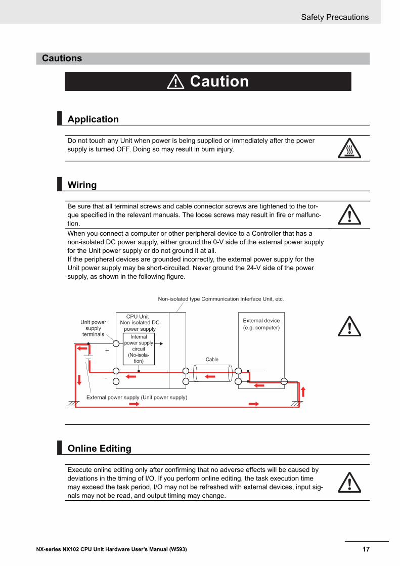
Be sure that all terminal screws and cable connector screws are tightened to the tor-que specified in the relevant manuals. The loose screws may result in fire or malfunc-tion.When you connect a computer or other peripheral device to a Controller that has anon-isolated DC power supply, either ground the 0-V side of the external power supplyfor the Unit power supply or do not ground it at all.If the peripheral devices are grounded incorrectly, the external power supply for theUnit power supply may be short-circuited. Never ground the 24-V side of the powersupply, as shown in the following figure.
Internal power supply
circuit(No-isola-
tion)
CPU Unit
Cable
External device
(e.g. computer)
External power supply (Unit power supply)
Non-isolated type Communication Interface Unit, etc.
Unit power supply
terminals
Non-isolated DC
power supply
Online Editing
Execute online editing only after confirming that no adverse effects will be caused bydeviations in the timing of I/O. If you perform online editing, the task execution timemay exceed the task period, I/O may not be refreshed with external devices, input sig-nals may not be read, and output timing may change.
Safety Precautions
17NX-series NX102 CPU Unit Hardware User’s Manual (W593)
Precautions for Safe Use
Transporting and Disassembly• Do not attempt to disassemble, repair, or modify any Units. Doing so may result in malfunction or
fire.• Do not drop any Unit or subject it to abnormal vibration or shock. Doing so may result in Unit mal-
function or burning.• When transporting any Unit, use the special packing box for it. Also, do not subject the Unit to ex-
cessive vibration or shock during transportation.
Mounting• Always turn OFF the power supply before mounting the Units. If the power supply is not OFF, the
Unit may result in malfunction or may be damaged.• Do not apply labels or tape to the Unit. When the Unit is installed or removed, adhesive or scraps
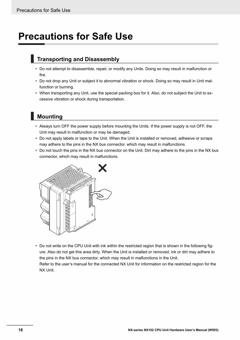
may adhere to the pins in the NX bus connector, which may result in malfunctions.• Do not touch the pins in the NX bus connector on the Unit. Dirt may adhere to the pins in the NX bus
connector, which may result in malfunctions.
• Do not write on the CPU Unit with ink within the restricted region that is shown in the following fig-ure. Also do not get this area dirty. When the Unit is installed or removed, ink or dirt may adhere tothe pins in the NX bus connector, which may result in malfunctions in the Unit.Refer to the user’s manual for the connected NX Unit for information on the restricted region for theNX Unit.
Precautions for Safe Use
18 NX-series NX102 CPU Unit Hardware User’s Manual (W593)
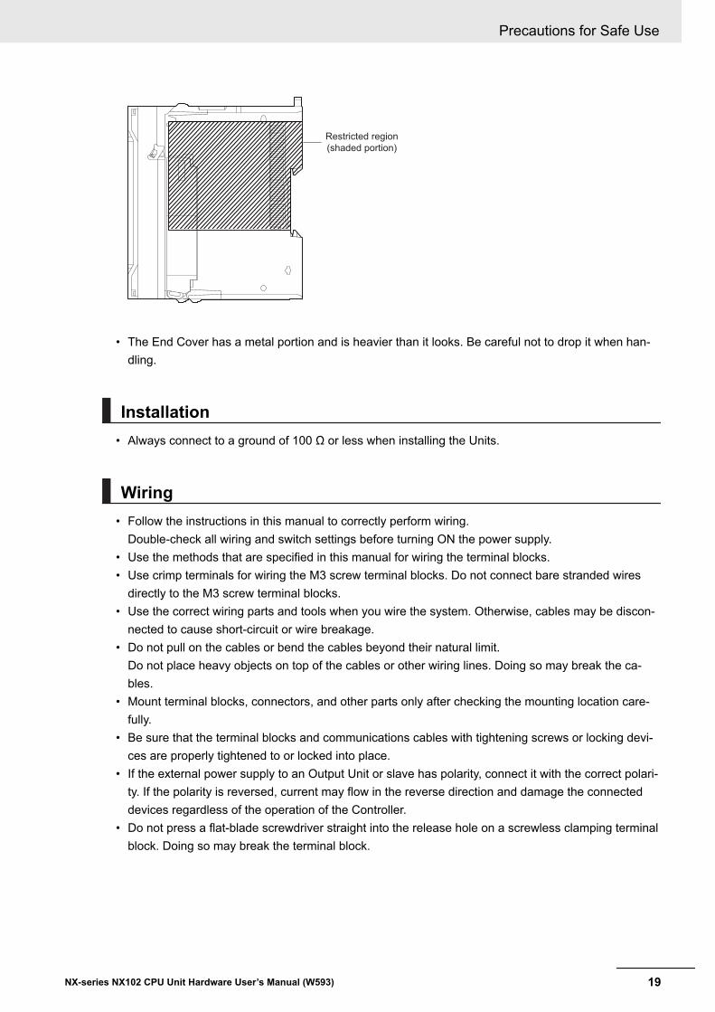
Restricted region
(shaded portion)
• The End Cover has a metal portion and is heavier than it looks. Be careful not to drop it when han-dling.
Installation• Always connect to a ground of 100 Ω or less when installing the Units.
Wiring• Follow the instructions in this manual to correctly perform wiring.
Double-check all wiring and switch settings before turning ON the power supply.• Use the methods that are specified in this manual for wiring the terminal blocks.• Use crimp terminals for wiring the M3 screw terminal blocks. Do not connect bare stranded wires
directly to the M3 screw terminal blocks.• Use the correct wiring parts and tools when you wire the system. Otherwise, cables may be discon-
nected to cause short-circuit or wire breakage.• Do not pull on the cables or bend the cables beyond their natural limit.
Do not place heavy objects on top of the cables or other wiring lines. Doing so may break the ca-bles.
• Mount terminal blocks, connectors, and other parts only after checking the mounting location care-fully.
• Be sure that the terminal blocks and communications cables with tightening screws or locking devi-ces are properly tightened to or locked into place.
• If the external power supply to an Output Unit or slave has polarity, connect it with the correct polari-ty. If the polarity is reversed, current may flow in the reverse direction and damage the connecteddevices regardless of the operation of the Controller.
• Do not press a flat-blade screwdriver straight into the release hole on a screwless clamping terminalblock. Doing so may break the terminal block.
Precautions for Safe Use
19NX-series NX102 CPU Unit Hardware User’s Manual (W593)
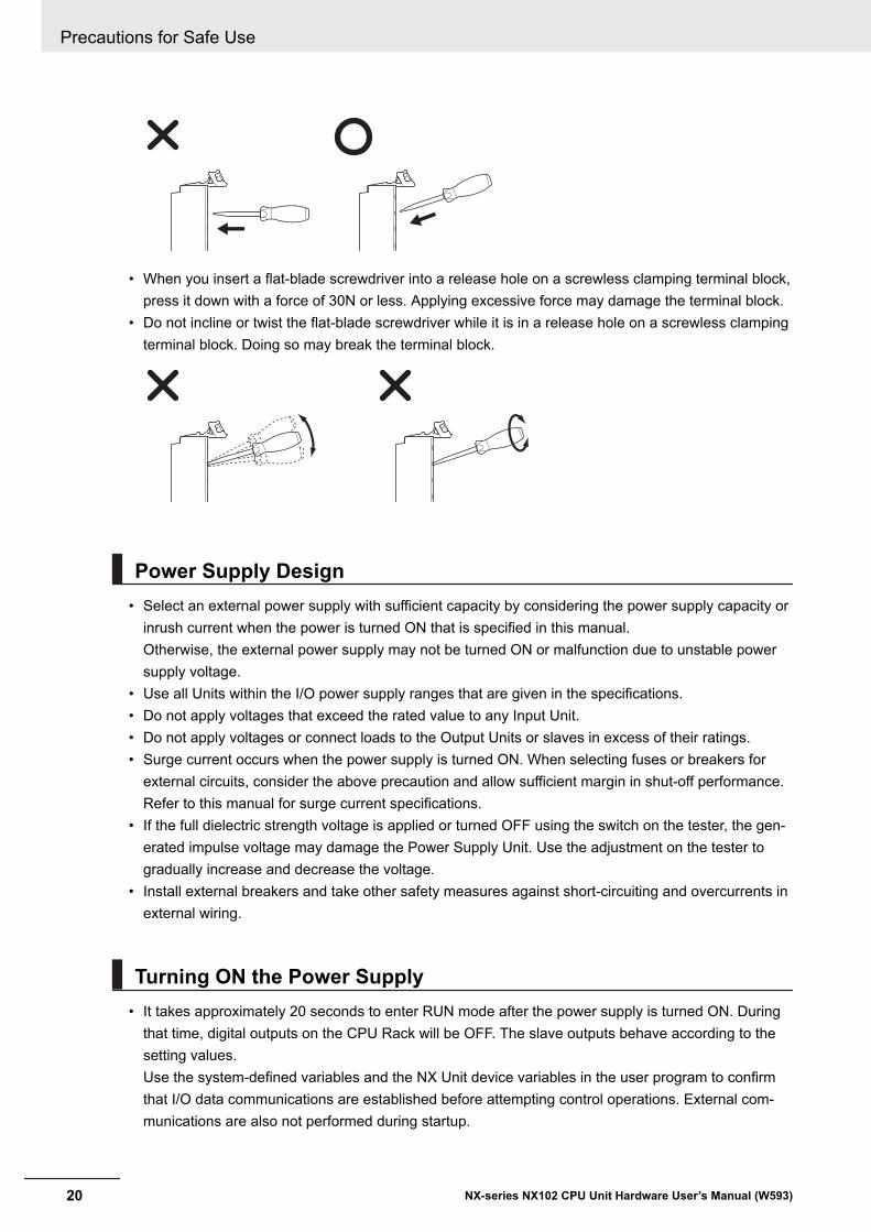
• When you insert a flat-blade screwdriver into a release hole on a screwless clamping terminal block,press it down with a force of 30N or less. Applying excessive force may damage the terminal block.
• Do not incline or twist the flat-blade screwdriver while it is in a release hole on a screwless clampingterminal block. Doing so may break the terminal block.
Power Supply Design• Select an external power supply with sufficient capacity by considering the power supply capacity or
inrush current when the power is turned ON that is specified in this manual.Otherwise, the external power supply may not be turned ON or malfunction due to unstable powersupply voltage.
• Use all Units within the I/O power supply ranges that are given in the specifications.• Do not apply voltages that exceed the rated value to any Input Unit.• Do not apply voltages or connect loads to the Output Units or slaves in excess of their ratings.• Surge current occurs when the power supply is turned ON. When selecting fuses or breakers for
external circuits, consider the above precaution and allow sufficient margin in shut-off performance.Refer to this manual for surge current specifications.
• If the full dielectric strength voltage is applied or turned OFF using the switch on the tester, the gen-erated impulse voltage may damage the Power Supply Unit. Use the adjustment on the tester togradually increase and decrease the voltage.
• Install external breakers and take other safety measures against short-circuiting and overcurrents inexternal wiring.
Turning ON the Power Supply• It takes approximately 20 seconds to enter RUN mode after the power supply is turned ON. During
that time, digital outputs on the CPU Rack will be OFF. The slave outputs behave according to thesetting values.Use the system-defined variables and the NX Unit device variables in the user program to confirmthat I/O data communications are established before attempting control operations. External com-munications are also not performed during startup.
Precautions for Safe Use
20 NX-series NX102 CPU Unit Hardware User’s Manual (W593)
• Configure the external circuits so that the power supply to the control system turns ON only after thepower supply to the Controller has turned ON. If the power supply to the Controller is turned ONafter the control power supply, temporary errors may result in incorrect control system signals be-cause the output terminals on Output Units may momentarily turn ON when power supply is turnedON to the Controller.
• If you transfer data from a backup file on an SD Memory Card to the Controller when the power sup-ply is turned ON, properly select the data groups to transfer. If the data for an unintended data groupis transferred to the Controller, it may cause the equipment to operate unpredictably.
• You cannot obtain normal input data from NX Units while the Units are restarting. Use the system-defined variables or device variables for the NX Units on the CPU Unit in the user program to checkthe validity of the I/O data before you attempt control operations.
Actual Operation• If you change the fail-soft operation setting, the output status when the error occurs may also
change. Confirm safety before you change the setting.• If you use fail-soft operation, write programming to determine whether Unit I/O data is valid. Without
such programming, the user program cannot distinguish between Units for which I/O refreshing iscontinued and Units for which I/O refreshing is stopped.
Turning OFF the Power Supply• Never turn OFF the power supply to the Controller when the BUSY indicator is flashing. While the
BUSY indicator is lit, the user program and settings in the CPU Unit are being backed up in the built-in non-volatile memory. This data will not be backed up correctly if the power supply is turned OFF.Also, a major fault level Controller error will occur the next time you start operation, and operationwill stop.
• Do not turn OFF the power supply or remove the SD Memory Card while SD Memory Card accessis in progress (i.e., while the SD BUSY indicator flashes). Data may become corrupted, and theController will not operate correctly if it uses corrupted data. To remove the SD Memory Card fromthe CPU Unit while the power supply is ON, press the SD Memory Card power supply switch andwait for the SD BUSY indicator and SD PWR indicator to turn OFF before you remove the SD Mem-ory Card.
• If the Unit power supply is turned OFF before the I/O power supply for the control system is turnedOFF, the output terminals of Output Units may malfunction and the control system may perform in-correct output temporarily. To avoid this problem, configure the external circuit to make sure that theUnit power supply is turned OFF only after the power supply for the control system is turned OFF.
• Do not disconnect the cable or turn OFF the power supply to the Controller when downloading dataor the user program from Support Software.
• Always turn OFF the power supply to the Controller before you attempt any of the following.a) Mounting or removing the Unitsb) Assembling the Unitsc) Setting DIP switches or rotary switchesd) Connecting cables or wiring the systeme) Connecting or disconnecting the terminal blocks or connectors
Precautions for Safe Use
21NX-series NX102 CPU Unit Hardware User’s Manual (W593)
The power supply circuit in the CPU Unit may continue to supply power to the Controller for a fewseconds after the power supply turns OFF. The POWER indicator is lit during this time. Confirm thatthe POWER indicator is not lit before you perform any of the above actions.
Operation• Confirm that no adverse effect will occur in the system before you attempt any of the following.
a) Changing the operating mode of the CPU Unit (including changing the setting of the StartupMode)
b) Changing the user program or settingsc) Changing set values or present valuesd) Forced refreshinge) Starting the CPU Unit with the battery exhaustedf) Restarting a slave or Unit after you change any settingsg) Transferring a backup file on the SD Memory Card
• After you change any slave or Unit settings, carefully check the safety of the controlled system be-fore you restart the Unit.
• If two different function modules are used together, such as when you use EtherNet/IP and Ether-CAT slaves, take suitable measures in the user program and external controls to ensure that safetyis maintained in the controlled system if one of the function modules stops. The relevant outputs willbehave according to the slave or Unit specifications if a partial fault level error occurs in one of thefunction modules.
• Always confirm safety at the connected equipment before you reset Controller errors with an eventlevel of partial fault or higher for the EtherCAT Master Function Module.When the error is reset, all slaves that were in any state other than Operational state due to a Con-troller error with an event level of partial fault or higher (in which outputs are disabled) will go to Op-erational state and the outputs will be enabled.Before you reset all errors or restart a slave, confirm that no Controller errors with an event level ofpartial fault have occurred for the EtherCAT Master Function Module.
Designing Tasks• If the following variables are specified for a condition expression when the execution condition of
event tasks is the same as the condition expression for a variable, event tasks may not be executedwhen conditions are met, or event tasks may be executed when conditions are not met.a) Structure members whose data size is 16 bits or more, except for system-defined variables for
motion controlb) Array elements whose data size is 16 bits or moreRefer to the NJ/NX-series CPU Unit Software User’s Manual (Cat. No. W501) for information onevent task execution conditions.
Battery Backup• If you use the clock data in the user program and turn OFF the power supply for a long time, use a
Battery which is sold separately.
Precautions for Safe Use
22 NX-series NX102 CPU Unit Hardware User’s Manual (W593)
The Battery is not mounted when the product is at factory setting. The clock data is retained by thebuilt-in capacitor. The capacitor is charged while the power is supplied and discharged while thepower is not supplied. If the power OFF time rate is high, the clock data is initialized and malfunc-tions may occur in the program for which the clock data is used.
• If you use the Battery, connect the Sysmac Studio and set the Battery-related error detection toUse. The Battery-related error detection is set to Do not use at the factory setting because theBattery is not built in. If the Battery-related error detection is set to Do not use, an error cannot bedetected when the Battery is exhausted and malfunctions may occur in the program for which theclock data is used.
Debugging• Forced refreshing ignores the results of user program execution and refreshes I/O with the specified
values. If forced refreshing is used for inputs for which I/O refreshing is not supported, the inputs willfirst take the specified values, but they will then be overwritten by the user program. Be careful thatthis operation differs from the force-set/reset functionality of the CJ/CP-series PLCs.
• You cannot upload or download information for forced refreshing with the Sysmac Studio.After downloading data that contains forced refreshing, change to RUN mode and then use the Sys-mac Studio to perform the operation for forced refreshing.Depending on the difference in the forced status, the control system may operate unexpectedly.
• Do not specify the same address for the AT specification for more than one variable.Doing so would allow the same entity to be accessed with different variable names, which wouldmake the user program more difficult to understand and possibly cause programming mistakes.
General Communications• When you use data link communications, check the error information that is given in _ErrSta (Con-
troller Error Status) to make sure that no error has occurred in the source device. Create a user pro-gram that uses reception data only when there is no error in the source device.If there is an error in the source device, the data for the data link may contain incorrect values.
• Unexpected operation may result if inappropriate data link tables are set. Even if appropriate datalink tables have been set, confirm that the controlled system will not be adversely affected beforeyou transfer the data link tables. The data links start automatically after the data link tables aretransferred.
EtherNet/IP Communications• Make sure to use the communications distance, number of nodes connected, and method of con-
nection for EtherNet/IP within specifications. Do not connect EtherNet/IP communications to Ether-CAT or other networks. An overload may cause the network to fail or malfunction.
• All related EtherNet/IP nodes are reset when you transfer settings for the built-in EtherNet/IP port(including IP addresses and tag data links settings). The settings can only be enabled after the re-set. Confirm that the system will not be adversely affected by resetting nodes before you transfer thesettings.
• If EtherNet/IP tag data links (cyclic communications) are used with a repeating hub, the communica-tions load on the network will increase. This will increase collisions and may prevent stable
Precautions for Safe Use
23NX-series NX102 CPU Unit Hardware User’s Manual (W593)
communications. Do not use repeating hubs on networks where tag data links are used. Use anEthernet switch instead.
EtherCAT Communications• Make sure to use the communications distance, number of nodes connected, and method of con-
nection for EtherCAT within specifications.Do not connect EtherCAT communications to EtherNet/IP, a standard in-house LAN, or other net-works. An overload may cause the network to fail or malfunction.
• Malfunctions or unexpected operation may occur for some combinations of EtherCAT revisions ofthe master and slaves. If you disable the revision check in the network settings, use the SysmacStudio to check the slave revision settings in the master and the actual slave revisions, and thenmake sure that functionality is compatible in the slave manuals or other references. You can checkthe actual slave revisions from the Sysmac Studio or on slave nameplates.
• After you transfer the user program, the CPU Unit is restarted and communications with the Ether-CAT slaves are cut off. During that period, the slave outputs behave according to the slave specifi-cations. The time that communications are cut off depends on the EtherCAT network configuration.Before you transfer the user program, confirm that the system will not be adversely affected.
• If the Fail-soft Operation parameter is set to stop operation, process data communications willstop for all slaves when an EtherCAT communications error is detected in a slave. At that time, theServo Drive will operate according to the Servo Drive specifications. Make sure that the Fail-soft Op-eration parameter setting results in safe operation when a device error occurs.
• Even if the Process Data Communication is stopped and subsequently restored automatically, takethe external safety measures or set the Fail-soft Operation Settings to Stop to make the system op-erate safe.
• EtherCAT communications are not always established immediately after the power supply is turnedON. Use the system-defined variables in the user program to confirm that communications are es-tablished before attempting control operations.
• If noise occurs or an EtherCAT slave is disconnected from the network, any current communicationsframes may be lost. If frames are lost, slave I/O data is not communicated, and unintended opera-tion may occur. The slave outputs will behave according to the slave specifications. Refer to themanual for the slave. If a noise countermeasure or slave replacement is required, perform the fol-lowing processing.a) Program the Input Data Invalid system-defined variable as an interlock condition in the user pro-
gram.b) Set the PDO communications timeout detection count setting in the EtherCAT master to at
least 2. Refer to the NJ/NX-series CPU Unit Built-in EtherCAT Port User’s Manual (Cat. No.W505) for details.
• When an EtherCAT slave is disconnected, communications will stop and control of the outputs willbe lost not only for the disconnected slave, but for all slaves connected after it through to the physi-cal end node. Confirm that the system will not be adversely affected before you disconnect a slave.
• I/O data communications of NX bus are not always established immediately after the power supplyis turned ON. Use the system-defined variables and the EtherCAT Coupler Unit device variables inthe user program to confirm that I/O data communications are established before attempting controloperations.
• You cannot use standard Ethernet hubs or repeater hubs with EtherCAT communications. If you useone of these, a major fault level error or other error may occur.
Precautions for Safe Use
24 NX-series NX102 CPU Unit Hardware User’s Manual (W593)
• If the actual configuration changes, for example, when actual configuration does not contain a disa-ble slave and subsequently you include it in the actual configuration, set the total cable length for thecase of the worst scenario.
Motion control• Confirm the axis number carefully before you perform an MC Test Run.• The motor is stopped if communications are interrupted between the Sysmac Studio and the CPU
Unit during an MC Test Run. Connect the communications cable between the computer and CPUUnit securely and confirm that the system will not be adversely affected before you perform an MCTest Run.
• Always execute the Save Cam Table instruction if you change any of the cam data from the userprogram in the CPU Unit or from the Sysmac Studio. If the cam data is not saved, the previous con-dition will be restored when the power is turned ON again, possibly causing unexpected machineoperation.
• The positive drive prohibit input (POT), negative drive prohibit input (NOT), and home proximity in-put (DEC) of the Servo Drive are used by the MC Function Module as the positive limit input, nega-tive limit input, and home proximity input. Make sure that the signal widths for all of these input sig-nals are longer than the control period of the MC Function Module. If the input signal widths areshorter than the control period, the MC Function Module may not be able to detect the input signals,resulting in incorrect operation.
• If you make any changes in the Detailed Settings Area of the Axis Basic Settings Display of theSysmac Studio, make sure that the devices or machines perform the expected operation before youstart actual operation.If the relationship between the functions of the Motion Control Function Module and the EtherCATslave process data that is assigned to the axes is not correct, the devices or machines may performunexpected operation.
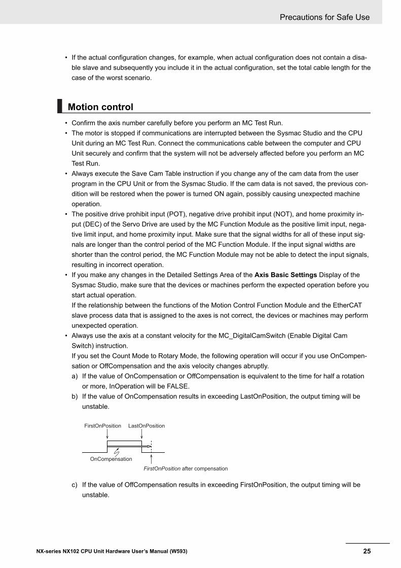
• Always use the axis at a constant velocity for the MC_DigitalCamSwitch (Enable Digital CamSwitch) instruction.If you set the Count Mode to Rotary Mode, the following operation will occur if you use OnCompen-sation or OffCompensation and the axis velocity changes abruptly.a) If the value of OnCompensation or OffCompensation is equivalent to the time for half a rotation
or more, InOperation will be FALSE.b) If the value of OnCompensation results in exceeding LastOnPosition, the output timing will be
unstable.
FirstOnPosition LastOnPosition
OnCompensation
FirstOnPosition after compensation
c) If the value of OffCompensation results in exceeding FirstOnPosition, the output timing will beunstable.
Precautions for Safe Use
25NX-series NX102 CPU Unit Hardware User’s Manual (W593)
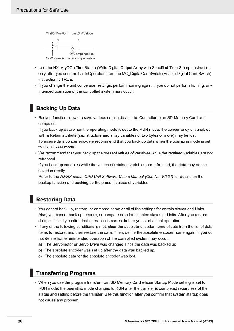
FirstOnPosition LastOnPosition
OffCompensation
LastOnPosition after compensation
• Use the NX_AryDOutTimeStamp (Write Digital Output Array with Specified Time Stamp) instructiononly after you confirm that InOperation from the MC_DigitalCamSwitch (Enable Digital Cam Switch)instruction is TRUE.
• If you change the unit conversion settings, perform homing again. If you do not perform homing, un-intended operation of the controlled system may occur.
Backing Up Data• Backup function allows to save various setting data in the Controller to an SD Memory Card or a
computer.If you back up data when the operating mode is set to the RUN mode, the concurrency of variableswith a Retain attribute (i.e., structure and array variables of two bytes or more) may be lost.To ensure data concurrency, we recommend that you back up data when the operating mode is setto PROGRAM mode.
• We recommend that you back up the present values of variables while the retained variables are notrefreshed.If you back up variables while the values of retained variables are refreshed, the data may not besaved correctly.Refer to the NJ/NX-series CPU Unit Software User’s Manual (Cat. No. W501) for details on thebackup function and backing up the present values of variables.
Restoring Data• You cannot back up, restore, or compare some or all of the settings for certain slaves and Units.
Also, you cannot back up, restore, or compare data for disabled slaves or Units. After you restoredata, sufficiently confirm that operation is correct before you start actual operation.
• If any of the following conditions is met, clear the absolute encoder home offsets from the list of dataitems to restore, and then restore the data. Then, define the absolute encoder home again. If you donot define home, unintended operation of the controlled system may occur.a) The Servomotor or Servo Drive was changed since the data was backed up.b) The absolute encoder was set up after the data was backed up.c) The absolute data for the absolute encoder was lost.
Transferring Programs• When you use the program transfer from SD Memory Card whose Startup Mode setting is set to
RUN mode, the operating mode changes to RUN after the transfer is completed regardless of thestatus and setting before the transfer. Use this function after you confirm that system startup doesnot cause any problem.
Precautions for Safe Use
26 NX-series NX102 CPU Unit Hardware User’s Manual (W593)
• Always confirm safety at the connected equipment before you perform the following operationswhen the device output hold configuration is set to enable. The equipment may operate unexpected-ly because the last status for outputs is retained.a) Changing the operating mode of the CPU Unitb) When downloaded
• When you transfer the values retained in the memory of the CJ-series Units, always check the setvalues of the Device Output Hold Configuration and make sure that the destination is safe.The devices or machines may perform unexpected operation regardless of the operating mode ofthe CPU Unit.
Battery Installation and Replacement• The Battery may leak, rupture, heat, or ignite. Never short-circuit, charge, disassemble, heat, or in-
cinerate the Battery or subject it to strong shock.• Dispose of any Battery that has been dropped on the floor or otherwise subjected to excessive
shock. Batteries that have been subjected to shock may leak if they are used.• Apply power for at least five minutes before changing the Battery. Install a new Battery within five
minutes (at 25°C) of turning OFF the power supply. If power is not supplied for at least 5 minutes,the retained clock data may be initialized.
• We recommend mounting or replacing the Battery with the power turned OFF to prevent the CPUUnit’s sensitive internal components from being damaged by static electricity and to prevent mal-functions. The Battery can be mounted or replaced without turning OFF the power supply. To do so,always touch a grounded piece of metal to discharge static electricity from your body before youstart the procedure.If the Low Battery Voltage error occurs after you mount the Battery, connect the Sysmac Studio andclear the error.
Unit Replacement• Make sure that the required data, including the user program, configurations, settings, and varia-
bles, is transferred to a CPU Unit that was replaced and to externally connected devices before re-starting operation. Be sure to include the tag data link settings and routing tables, which are storedin the CPU Unit.
• The absolute encoder home offsets are retained in the CPU Unit as absolute encoder information.When you change the combination of the CPU Unit and Servomotor, e.g., when you add or replacea Servomotor, define the absolute encoder home again.
• Always turn OFF the Unit power supply and I/O power supply before you remove the NX Unit.
Disposal• Dispose of the Units and Batteries according to local ordinances as they apply.
Precautions for Safe Use
27NX-series NX102 CPU Unit Hardware User’s Manual (W593)
• The following information must be displayed for all products that contain primary lithium batterieswith a perchlorate content of 6 ppb or higher when shipped to or transported through the State ofCalifornia, USA.Perchlorate Material - special handling may apply.See www.dtsc.ca.gov/hazardouswaste/perchlorate.
• The Battery is a primary lithium battery with a perchlorate content of 6 ppb or higher. Place theabove information on the individual boxes and shipping boxes when shipping finished products thatcontain a CPU Unit with a mounted Battery to the State of California, USA.
Precautions for Safe Use
28 NX-series NX102 CPU Unit Hardware User’s Manual (W593)

Precautions for Correct Use
Storage and Installation• Follow the instructions in this manual to correctly perform installation.• Do not operate or store the Controller in the following locations. Doing so may result in burning, in
operation stopping, or in malfunction.a) Locations subject to direct sunlightb) Locations subject to temperatures or humidity outside the range specified in the specificationsc) Locations subject to condensation as the result of severe changes in temperatured) Locations subject to corrosive or flammable gasese) Locations subject to dust (especially iron dust) or saltsf) Locations subject to exposure to water, oil, or chemicalsg) Locations subject to shock or vibration
• Take appropriate and sufficient countermeasures when installing the Controller in the following loca-tions.a) Locations subject to strong, high-frequency noiseb) Locations subject to static electricity or other forms of noisec) Locations subject to strong electromagnetic fieldsd) Locations subject to possible exposure to radioactivitye) Locations close to power lines
• Before touching a Unit, be sure to first touch a grounded metallic object in order to discharge anystatic build-up.
• Install the Controller away from sources of heat and ensure proper ventilation. Not doing so may re-sult in malfunction, in operation stopping, or in burning.
Mounting• When you install the Unit, be careful not to touch or bump the pins in the NX bus connector.• When you handle the Unit, be careful not to apply stress to the pins in the NX bus connector.
If the Unit is installed and the power supply is turned ON when the pins in the NX bus connector aredeformed, contact failure may cause malfunctions.
• Always mount an End Cover to the end of the CPU Rack to protect the last Unit on the CPU Rack.Not mounting the End Cover may result in malfunction or failure of the CPU Unit.
• After you mount the Unit, always secure it with End Plates at both sides. If you do not secure it, theUnit may be damaged or malfunction.
• If you use DIN Track Insulation Spacers to install a CPU Rack, the height will be increased by ap-proximately 10 mm. Make sure that the CPU Rack and connecting cables do not come into contactwith other devices.
Wiring• Do not allow foreign matter to enter the openings in the Unit. Doing so may result in Unit burning,
electric shock, or failure.
Precautions for Correct Use
29NX-series NX102 CPU Unit Hardware User’s Manual (W593)
• Do not allow wire clippings, shavings, or other foreign material to enter any Unit. Otherwise, Unitburning, failure, or malfunction may occur. Cover the Units or take other suitable countermeasures,especially during wiring work.
• For EtherCAT and EtherNet/IP, use the connection methods and cables that are specified in theNJ/NX-series CPU Unit Built-in EtherCAT Port User’s Manual (Cat. No. W505) and the NJ/NX-seriesCPU Unit Built-in EtherNet/IP Port User’s Manual (Cat. No. W506). Otherwise, communications maybe faulty.
• Use the rated power supply voltage for the Units that supply power. Take appropriate measures toensure that the specified power with the rated voltage and frequency is supplied in places where thepower supply is unstable.
• Make sure that the current capacity of the wire is sufficient. Otherwise, excessive heat may be gen-erated. When cross-wiring terminals, the total current for all the terminals will flow in the wire. Whenwiring cross-overs, make sure that the current capacity of each of the wires is not exceeded.
• If you use reed switches for the input contacts for AC Input Units, use switches with a current ca-pacity of 1 A or greater.If reed switches with smaller allowable currents are used, the contacts may fuse due to surge cur-rents.
Operation• Confirm the device output hold configuration before you change the operating mode of the CPU Unit
or execute the download.• Take safety measures for the controlled system as well.
Error Processing• In applications that use the results of instructions that read the error status, consider the affect on
the system when errors are detected and program error processing accordingly. For example, eventhe detection of a minor error, such as Battery replacement during operation, can affect the systemdepending on how the user program is written.
• If you change the event level of a Controller error, the output status when the error occurs may alsochange. Confirm safety before use.
Restoring and Automatically Transferring Data• When you edit the restore command file or the automatic transfer command file, do not change any-
thing in the file except for the “yes” and “no” specifications for the selectable data groups. If youchange anything else in the file, the Controller may perform unexpected operation when you restoreor automatically transfer the data.
• To prevent an unexpected restoration, set to enter the password for each execution before the re-store operation.
Precautions for Correct Use
30 NX-series NX102 CPU Unit Hardware User’s Manual (W593)
Transferring Programs• If you use the program transfer from SD Memory Card, set to enter the password for each execution
to prevent an unexpected program transfer.
Replacing Slaves and Units• If you replace a slave or Unit, refer to the operation manual for the slave or Unit for information on
the data required for individual slaves or Units and redo the necessary settings.
Task Settings• If a Task Period Exceeded error occurs, shorten the programs to fit in the task period or increase the
setting of the task period.
Motion control• Use the system-defined variable in the user program to confirm that EtherCAT communications are
established before you attempt to execute motion control instructions. Motion control instructions arenot executed normally if EtherCAT communications are not established.
• Use the system-defined variables to monitor for errors in communications with the slaves that arecontrolled by the motion control function module. Motion control instructions are not executed nor-mally if an error occur in slave communications.
• Before you start an MC Test Run, make sure that the operation parameters are set correctly.• Do not download motion control settings during an MC Test Run.
EtherCAT Communications• If you need to disconnect an EtherCAT slave cable during an operation, specify the disconnection of
the software connection of the EtherCAT slave first.Apply the Disable function for those EtherCAT slaves which you plan to replace in the future. If youneed to replace an EtherCAT slave due to a failure or other troubles, be sure to specify disconnect-ing the software connection.
• Set the Servo Drives to stop operation if an error occurs in EtherCAT communications between theController and a Servo Drive.
• Make sure that all of the slaves to be restored are participating in the network before you reset aNetwork Configuration Verification Error, Process Data Communications Error, or Link OFF Error inthe EtherCAT Master Function Module. If any slave is not participating when any of these errors isreset, the EtherCAT Master Function Module may access slave with a different node address thanthe specified node address or the error may not be reset correctly.
• Always use the specified EtherCAT slave cables. If you use any other cable, the EtherCAT masteror the EtherCAT slaves may detect an error and one of the following may occur.a) Continuous refreshing of process data communications will not be possible.b) Continuous refreshing of process data communications will not end during the set cycle.
Precautions for Correct Use
31NX-series NX102 CPU Unit Hardware User’s Manual (W593)
Battery Replacement• Be sure to mount a Battery within two years of the production date shown on the Battery label.• Turn ON the power after replacing the Battery for a CPU Unit that has been unused for a long time.
Leaving the CPU Unit unused again without turning ON the power even once after the Battery isreplaced may result in a shorter Battery life.
• If you use the Battery, use the CJ1W-BAT01 Battery Set which is sold separately.
SD Memory Cards• Insert the SD Memory Card all the way.• Do not turn OFF the power supply to the Controller during SD Memory Card access. The files may
be corrupted.If there is a corrupted file in the SD Memory Card, the file is automatically deleted by the restorationfunction when the power supply is turned ON.
• If you use an OMRON SD Memory Card, the end of the life of the SD Memory Card can be detectedin the following ways.a) _Card1Deteriorated (SD Memory Card Life Warning Flag) system-defined variableb) SD Memory Card Life Exceeded event in the event logWhen the end of the life is detected in any of the above ways, replace the SD Memory Card.
Debugging• When performing online editing, the CPU Unit saves a program updated by the online editing to
built-in non-volatile memory. Sysmac Studio shows a message that it is in a backup operation. Donot turn OFF the power supply to the Controller while this message is displayed. If the power supplyto the Controller is turned OFF, a Controller error will occur when the power supply is turned ONnext time.
• Data Tracing allows to sample the variables without any additional programming.If you set sampling to be performed on a specified task period and use data tracing to sample aninternal variable with a data size of 64 bits or more, members of a structure variable except for sys-tem-defined variable for motion control, or the elements of an array variable, specify the task thatassigns the program in which the target variable is defined or the program that refreshes the varia-ble for the sampling interval.If a different task is specified, the concurrency of variable values may not be ensured.
• If you use data tracing to sample the following variables, correct data may not be sampled.a) Structure members whose data size is 16 bits or more, except for system-defined variables for
motion controlb) Array elements whose data size is 16 bits or moreRefer to the NJ/NX-series CPU Unit Software User’s Manual (Cat. No. W501) for information on da-ta tracing.
Precautions for Correct Use
32 NX-series NX102 CPU Unit Hardware User’s Manual (W593)
Regulations and Standards
Conformance to EU Directives
Applicable Directives• EMC Directives• Low Voltage Directive
Concepts
l EMC DirectivesOMRON devices that comply with EU Directives also conform to the related EMC standards so thatthey can be more easily built into other devices or the overall machine. The actual products havebeen checked for conformity to EMC standards.*1Whether the products conform to the standards in the system used by the customer, however, mustbe checked by the customer. EMC-related performance of the OMRON devices that comply withEU Directives will vary depending on the configuration, wiring, and other conditions of the equip-ment or control panel on which the OMRON devices are installed. The customer must, therefore,perform the final check to confirm that devices and the overall machine conform to EMC standards.*1. Applicable EMC (Electromagnetic Compatibility) standards are as follows: EMS (Electromagnetic Suscept-
ibility): EN 61131-2 EMI (Electromagnetic Interference): EN 61131-2 (Radiated emission: 10-m regula-tions).
l Low Voltage DirectiveAlways ensure that devices operating at voltages of 50 to 1,000 VAC and 75 to 1,500 VDC meetthe required safety standards. The applicable directive is EN 61010-2-201.
l Conformance to EU DirectivesThe NX-series Units comply with EU Directives. To ensure that the machine or device in which theNX-series Units are used complies with EU Directives, the following precautions must be observed.• The NX-series Units must be installed within a control panel.• You must use SELV power supply for the DC power supplies that are connected as the Unit pow-
er supplies and I/O power supplies for the NX-series Units. EMC standard compliance was con-firmed for the OMRON S8VK-S Series DC Power Supplies.
• NX-series Units that comply with EU Directives also conform to the Common Emission Standard.Radiated emission characteristics (10-m regulations) may vary depending on the configuration ofthe control panel used, other devices connected to the control panel, wiring, and other condi-tions.You must therefore confirm that the overall machine or equipment in which the NX-series Unitsare used complies with EU Directives.
• This is a Class A product (for industrial environments). In a residential environment, it may causeradio interference. If radio interference occurs, the user may be required to take appropriatemeasures.
Regulations and Standards
33NX-series NX102 CPU Unit Hardware User’s Manual (W593)
Conformance to UL and CSA StandardsSome NX-series products comply with UL and CSA standards.If you use a product that complies with UL or CSA standards and must apply those standards to yourmachinery or devices, refer to the Instruction Sheet that is provided with the product. The InstructionSheet provides the application conditions for complying with the standards.
Conformance to KC StandardsObserve the following precaution if you use NX-series Units in Korea.
Class A Device (Broadcasting Communications Device for Office Use)This device obtained EMC registration for office use (Class A), and it is intended to be used in placesother than homes.Sellers and/or users need to take note of this.
Usage Conditions for KC StandardsTake the same measures as those described in Conformance to EU Directives on page 33. In addi-tion, attach a clamp core to the port side of the EtherNet/IP cable.The recommended clamp core is given below.
Recommended Clamp Core
Manufacturer Product Model Turns of cableNEC TOKIN Clamp core ESD-SR-250 1 turn
Software Licenses and CopyrightsThis product incorporates certain third party software. The license and copyright information associat-ed with this software is available at http://www.fa.omron.co.jp/nj_info_e/.
Regulations and Standards
34 NX-series NX102 CPU Unit Hardware User’s Manual (W593)
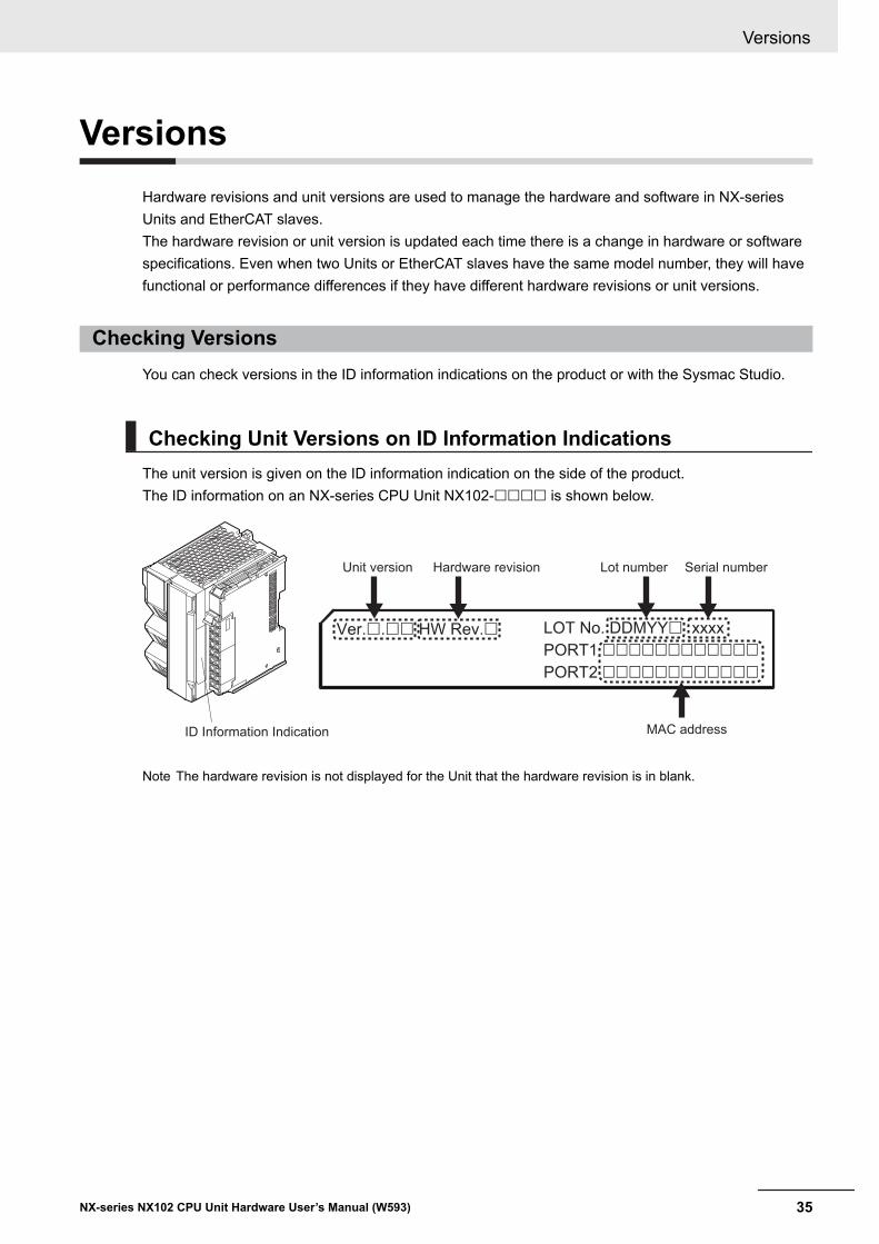
VersionsHardware revisions and unit versions are used to manage the hardware and software in NX-seriesUnits and EtherCAT slaves.The hardware revision or unit version is updated each time there is a change in hardware or softwarespecifications. Even when two Units or EtherCAT slaves have the same model number, they will havefunctional or performance differences if they have different hardware revisions or unit versions.
Checking VersionsYou can check versions in the ID information indications on the product or with the Sysmac Studio.
Checking Unit Versions on ID Information IndicationsThe unit version is given on the ID information indication on the side of the product.The ID information on an NX-series CPU Unit NX102-££££ is shown below.
ID Information Indication
Unit version Hardware revision Lot number Serial number
MAC address
LOT No. DDMYY£ xxxx
PORT1 ££££££££££££
PORT2 ££££££££££££
Ver.£.££ HW Rev.£
Note The hardware revision is not displayed for the Unit that the hardware revision is in blank.
Versions
35NX-series NX102 CPU Unit Hardware User’s Manual (W593)
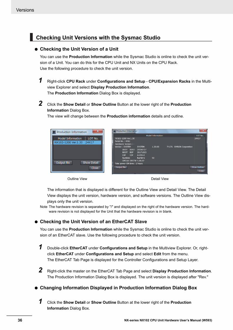
Checking Unit Versions with the Sysmac Studio
l Checking the Unit Version of a UnitYou can use the Production Information while the Sysmac Studio is online to check the unit ver-sion of a Unit. You can do this for the CPU Unit and NX Units on the CPU Rack.Use the following procedure to check the unit version.
1 Right-click CPU Rack under Configurations and Setup - CPU/Expansion Racks in the Multi-view Explorer and select Display Production Information.The Production Information Dialog Box is displayed.
2 Click the Show Detail or Show Outline Button at the lower right of the ProductionInformation Dialog Box.The view will change between the Production information details and outline.
Outline View Detail View
The information that is displayed is different for the Outline View and Detail View. The DetailView displays the unit version, hardware version, and software versions. The Outline View dis-plays only the unit version.
Note The hardware revision is separated by "/" and displayed on the right of the hardware version. The hard-ware revision is not displayed for the Unit that the hardware revision is in blank.
l Checking the Unit Version of an EtherCAT SlaveYou can use the Production Information while the Sysmac Studio is online to check the unit ver-sion of an EtherCAT slave. Use the following procedure to check the unit version.
1 Double-click EtherCAT under Configurations and Setup in the Multiview Explorer. Or, right-click EtherCAT under Configurations and Setup and select Edit from the menu.The EtherCAT Tab Page is displayed for the Controller Configurations and Setup Layer.
2 Right-click the master on the EtherCAT Tab Page and select Display Production Information.The Production Information Dialog Box is displayed. The unit version is displayed after "Rev."
l Changing Information Displayed in Production Information Dialog Box
1 Click the Show Detail or Show Outline Button at the lower right of the ProductionInformation Dialog Box.
Versions
36 NX-series NX102 CPU Unit Hardware User’s Manual (W593)
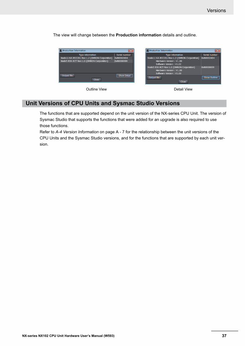
The view will change between the Production information details and outline.
Outline View Detail View
Unit Versions of CPU Units and Sysmac Studio VersionsThe functions that are supported depend on the unit version of the NX-series CPU Unit. The version ofSysmac Studio that supports the functions that were added for an upgrade is also required to usethose functions.Refer to A-4 Version Information on page A - 7 for the relationship between the unit versions of theCPU Units and the Sysmac Studio versions, and for the functions that are supported by each unit ver-sion.
Versions
37NX-series NX102 CPU Unit Hardware User’s Manual (W593)
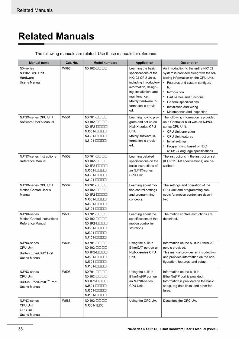
Related ManualsThe following manuals are related. Use these manuals for reference.
Manual name Cat. No. Model numbers Application DescriptionNX-seriesNX102 CPU UnitHardwareUser’s Manual
W593 NX102-££££ Learning the basicspecifications of theNX102 CPU Units,including introductoryinformation, design-ing, installation, andmaintenance.Mainly hardware in-formation is provid-ed.
An introduction to the entire NX102system is provided along with the fol-lowing information on the CPU Unit.• Features and system configura-
tion• Introduction• Part names and functions• General specifications• Installation and wiring• Maintenance and Inspection
NJ/NX-series CPU UnitSoftware User’s Manual
W501 NX701-££££NX102-££££NX1P2-££££NJ501-££££NJ301-££££NJ101-££££
Learning how to pro-gram and set up anNJ/NX-series CPUUnit.Mainly software in-formation is provid-ed.
The following information is providedon a Controller built with an NJ/NX-series CPU Unit.• CPU Unit operation• CPU Unit features• Initial settings• Programming based on IEC
61131-3 language specificationsNJ/NX-series InstructionsReference Manual
W502 NX701-££££NX102-££££NX1P2-££££NJ501-££££NJ301-££££NJ101-££££
Learning detailedspecifications on thebasic instructions ofan NJ/NX-seriesCPU Unit.
The instructions in the instruction set(IEC 61131-3 specifications) are de-scribed.
NJ/NX-series CPU UnitMotion Control User’sManual
W507 NX701-££££NX102-££££NX1P2-££££NJ501-££££NJ301-££££NJ101-££££
Learning about mo-tion control settingsand programmingconcepts.
The settings and operation of theCPU Unit and programming con-cepts for motion control are descri-bed.
NJ/NX-seriesMotion Control InstructionsReference Manual
W508 NX701-££££NX102-££££NX1P2-££££NJ501-££££NJ301-££££NJ101-££££
Learning about thespecifications of themotion control in-structions.
The motion control instructions aredescribed.
NJ/NX-seriesCPU Unit
Built-in EtherCAT® PortUser’s Manual
W505 NX701-££££NX102-££££NX1P2-££££NJ501-££££NJ301-££££NJ101-££££
Using the built-inEtherCAT port on anNJ/NX-series CPUUnit.
Information on the built-in EtherCATport is provided.This manual provides an introductionand provides information on the con-figuration, features, and setup.
NJ/NX-seriesCPU Unit
Built-in EtherNet/IP™ PortUser’s Manual
W506 NX701-££££NX102-££££NX1P2-££££NJ501-££££NJ301-££££NJ101-££££
Using the built-inEtherNet/IP port onan NJ/NX-seriesCPU Unit.
Information on the built-inEtherNet/IP port is provided.Information is provided on the basicsetup, tag data links, and other fea-tures.
NJ/NX-seriesCPU UnitOPC UAUser’s Manual
W588 NX102-££££NJ501-1£00
Using the OPC UA. Describes the OPC UA.
Related Manuals
38 NX-series NX102 CPU Unit Hardware User’s Manual (W593)
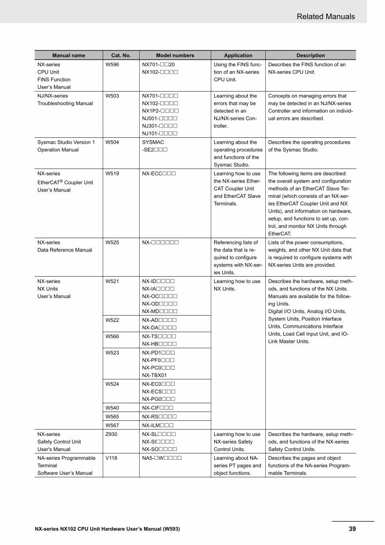
Manual name Cat. No. Model numbers Application DescriptionNX-seriesCPU UnitFINS FunctionUser’s Manual
W596 NX701-££20NX102-££££
Using the FINS func-tion of an NX-seriesCPU Unit.
Describes the FINS function of anNX-series CPU Unit.
NJ/NX-seriesTroubleshooting Manual
W503 NX701-££££NX102-££££NX1P2-££££NJ501-££££NJ301-££££NJ101-££££
Learning about theerrors that may bedetected in anNJ/NX-series Con-troller.
Concepts on managing errors thatmay be detected in an NJ/NX-seriesController and information on individ-ual errors are described.
Sysmac Studio Version 1Operation Manual
W504 SYSMAC-SE2£££
Learning about theoperating proceduresand functions of theSysmac Studio.
Describes the operating proceduresof the Sysmac Studio.
NX-series
EtherCAT® Coupler UnitUser’s Manual
W519 NX-ECC£££ Learning how to usethe NX-series Ether-CAT Coupler Unitand EtherCAT SlaveTerminals.
The following items are described:the overall system and configurationmethods of an EtherCAT Slave Ter-minal (which consists of an NX-ser-ies EtherCAT Coupler Unit and NXUnits), and information on hardware,setup, and functions to set up, con-trol, and monitor NX Units throughEtherCAT.
NX-seriesData Reference Manual
W525 NX-££££££ Referencing lists ofthe data that is re-quired to configuresystems with NX-ser-ies Units.
Lists of the power consumptions,weights, and other NX Unit data thatis required to configure systems withNX-series Units are provided.
NX-seriesNX UnitsUser’s Manual
W521 NX-ID££££NX-IA££££NX-OC££££NX-OD££££NX-MD££££
Learning how to useNX Units.
Describes the hardware, setup meth-ods, and functions of the NX Units.Manuals are available for the follow-ing Units.Digital I/O Units, Analog I/O Units,System Units, Position InterfaceUnits, Communications InterfaceUnits, Load Cell Input Unit, and IO-Link Master Units.
W522 NX-AD££££NX-DA££££
W566 NX-TS££££NX-HB££££
W523 NX-PD1£££NX-PF0£££NX-PC0£££NX-TBX01
W524 NX-EC0£££NX-ECS£££NX-PG0£££
W540 NX-CIF£££W565 NX-RS££££W567 NX-ILM£££
NX-seriesSafety Control UnitUser's Manual
Z930 NX-SL££££NX-SI££££NX-SO££££
Learning how to useNX-series SafetyControl Units.
Describes the hardware, setup meth-ods, and functions of the NX-seriesSafety Control Units.
NA-series ProgrammableTerminalSoftware User’s Manual
V118 NA5-£W££££ Learning about NA-series PT pages andobject functions.
Describes the pages and objectfunctions of the NA-series Program-mable Terminals.
Related Manuals
39NX-series NX102 CPU Unit Hardware User’s Manual (W593)
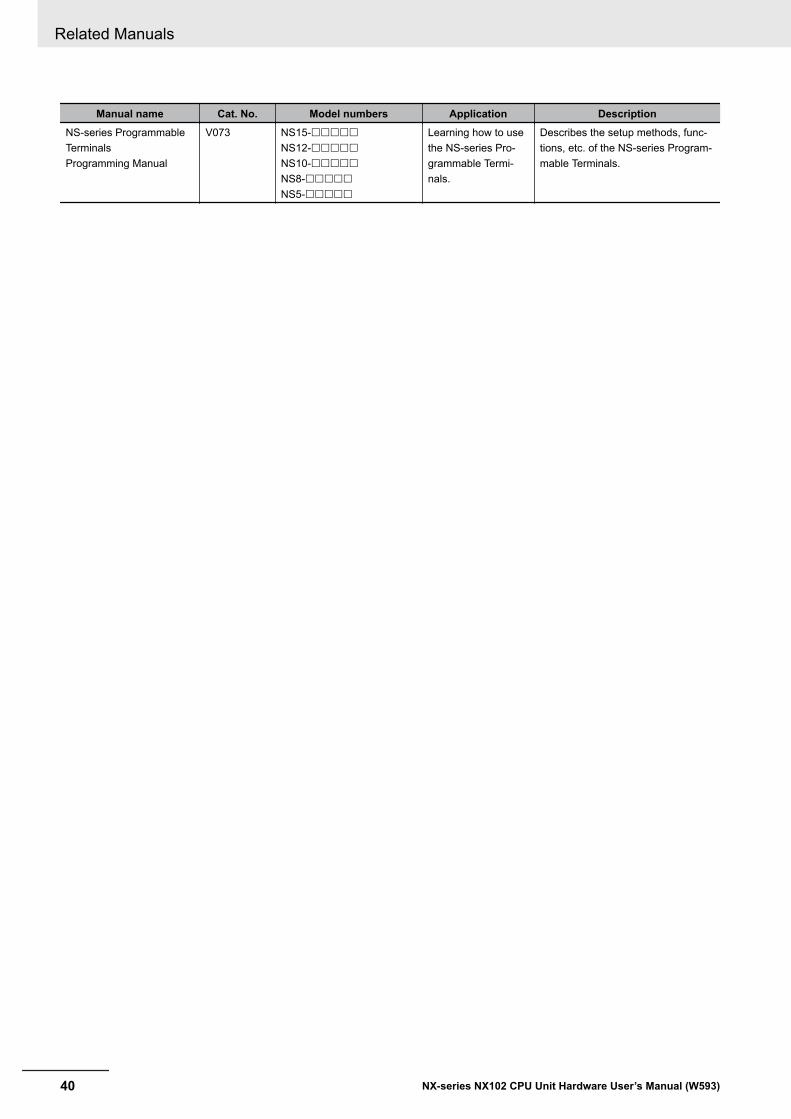
Manual name Cat. No. Model numbers Application DescriptionNS-series ProgrammableTerminalsProgramming Manual
V073 NS15-£££££NS12-£££££NS10-£££££NS8-£££££NS5-£££££
Learning how to usethe NS-series Pro-grammable Termi-nals.
Describes the setup methods, func-tions, etc. of the NS-series Program-mable Terminals.
Related Manuals
40 NX-series NX102 CPU Unit Hardware User’s Manual (W593)

TerminologyTerm Description
AT One of the attributes of a variable.This attribute allows the user to specify what is assigned to a variable. An I/Oport or an address in memory used for CJ-series Units can be specified.
CJ-series Unit Any of the CJ-series Units that can be used with an NJ-series Controller.memory used for CJ-series Units One type of I/O memory that contains addresses to which variables can be as-
signed, for example, when accessing a CJ-series Unit or CJ-series network. Itcan be accessed only with variables with an AT attribute.
CPU Unit The Unit that serves as the center of control for a Machine Automation Control-ler. The CPU Unit executes tasks, refreshes I/O for other Units and slaves, etc.The NJ/NX-series CPU Units include the NX701-££££, NX102-££££,NX1P2-££££, and NJ501-££££.
EtherCAT Master Function Module One of the function modules. This function module controls the EtherCAT slavesas the EtherCAT master.
EtherNet/IP Function Module One of the function modules. This function module controls the built-inEtherNet/IP port.
FB An acronym for "function block."FUN An abbreviation for "function."I/O port A logical interface that is used by the CPU Unit to exchange data with an exter-
nal device (slave or Unit).I/O map settings Settings that assign variables to I/O ports. Assignment information between I/O
ports and variables.I/O refreshing Cyclic data exchange with external devices that is performed with predetermined
memory addresses.MC Test Run A function to check motor operation and wiring from the Sysmac Studio.NX bus The NX-series internal bus. NX102 and NX1P2 CPU Units have the NX bus.NX Units Any of the NX-series Units that perform I/O processing with connected external
devices. The Communications Coupler Units are not included with the NX Units.PDO communications An abbreviation for process data communications. Data is exchanged between
the master and slaves on a process data communications cycle. (The processdata communications cycle is the same as the task period of the primary periodictask.)
PLC Function Module One of the function modules. This function module executes the user program,sends commands to the Motion Control Function Module, and provides an inter-face to the USB and SD Memory Card.
POU An acronym for "program organization unit." A POU is a unit in a program execu-tion model that is defined in IEC 61131-3.A POU contains an algorithm and a local variable table and forms the basic unitused to build a user program.There are three types of POUs: programs, functions, and function blocks.
SDO communications One type of EtherCAT communications in which service data objects (SDOs) areused to transmit information whenever required.
Sysmac Studio A computer software application for setting, programming, debugging, and trou-bleshooting NJ/NX-series Controllers. It also provides operations for motion con-trol and a Simulator.
upload To transfer data from the Controller to the Sysmac Studio with the synchroniza-tion operation of the Sysmac Studio.
Terminology
41NX-series NX102 CPU Unit Hardware User’s Manual (W593)
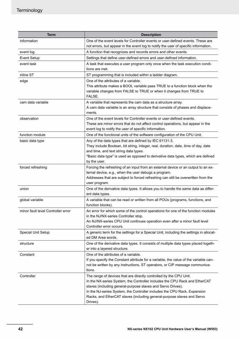
Term Descriptioninformation One of the event levels for Controller events or user-defined events. These are
not errors, but appear in the event log to notify the user of specific information.event log A function that recognizes and records errors and other events.Event Setup Settings that define user-defined errors and user-defined information.event task A task that executes a user program only once when the task execution condi-
tions are met.inline ST ST programming that is included within a ladder diagram.edge One of the attributes of a variable.
This attribute makes a BOOL variable pass TRUE to a function block when thevariable changes from FALSE to TRUE or when it changes from TRUE toFALSE.
cam data variable A variable that represents the cam data as a structure array.A cam data variable is an array structure that consists of phases and displace-ments.
observation One of the event levels for Controller events or user-defined events.These are minor errors that do not affect control operations, but appear in theevent log to notify the user of specific information.
function module One of the functional units of the software configuration of the CPU Unit.basic data type Any of the data types that are defined by IEC 61131-3.
They include Boolean, bit string, integer, real, duration, date, time of day, dateand time, and text string data types."Basic data type" is used as opposed to derivative data types, which are definedby the user.
forced refreshing Forcing the refreshing of an input from an external device or an output to an ex-ternal device, e.g., when the user debugs a program.Addresses that are subject to forced refreshing can still be overwritten from theuser program.
union One of the derivative data types. It allows you to handle the same data as differ-ent data types.
global variable A variable that can be read or written from all POUs (programs, functions, andfunction blocks).
minor fault level Controller error An error for which some of the control operations for one of the function modulesin the NJ/NX-series Controller stop.An NJ/NX-series CPU Unit continues operation even after a minor fault levelController error occurs.
Special Unit Setup A generic term for the settings for a Special Unit, including the settings in allocat-ed DM Area words.
structure One of the derivative data types. It consists of multiple data types placed togeth-er into a layered structure.
Constant One of the attributes of a variable.If you specify the Constant attribute for a variable, the value of the variable can-not be written by any instructions, ST operators, or CIP message communica-tions.
Controller The range of devices that are directly controlled by the CPU Unit.In the NX-series System, the Controller includes the CPU Rack and EtherCATslaves (including general-purpose slaves and Servo Drives).In the NJ-series System, the Controller includes the CPU Rack, ExpansionRacks, and EtherCAT slaves (including general-purpose slaves and ServoDrives).
Terminology
42 NX-series NX102 CPU Unit Hardware User’s Manual (W593)
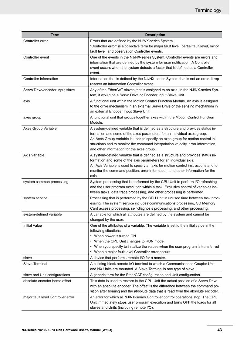
Term DescriptionController error Errors that are defined by the NJ/NX-series System.
“Controller error” is a collective term for major fault level, partial fault level, minorfault level, and observation Controller events.
Controller event One of the events in the NJ/NX-series System. Controller events are errors andinformation that are defined by the system for user notification. A Controllerevent occurs when the system detects a factor that is defined as a Controllerevent.
Controller information Information that is defined by the NJ/NX-series System that is not an error. It rep-resents an information Controller event.
Servo Drive/encoder input slave Any of the EtherCAT slaves that is assigned to an axis. In the NJ/NX-series Sys-tem, it would be a Servo Drive or Encoder Input Slave Unit.
axis A functional unit within the Motion Control Function Module. An axis is assignedto the drive mechanism in an external Servo Drive or the sensing mechanism inan external Encoder Input Slave Unit.
axes group A functional unit that groups together axes within the Motion Control FunctionModule.
Axes Group Variable A system-defined variable that is defined as a structure and provides status in-formation and some of the axes parameters for an individual axes group.An Axes Group Variable is used to specify an axes group for motion control in-structions and to monitor the command interpolation velocity, error information,and other information for the axes group.
Axis Variable A system-defined variable that is defined as a structure and provides status in-formation and some of the axis parameters for an individual axis.An Axis Variable is used to specify an axis for motion control instructions and tomonitor the command position, error information, and other information for theaxis.
system common processing System processing that is performed by the CPU Unit to perform I/O refreshingand the user program execution within a task. Exclusive control of variables be-tween tasks, data trace processing, and other processing is performed.
system service Processing that is performed by the CPU Unit in unused time between task proc-essing. The system service includes communications processing, SD MemoryCard access processing, self-diagnosis processing, and other processing.
system-defined variable A variable for which all attributes are defined by the system and cannot bechanged by the user.
Initial Value One of the attributes of a variable. The variable is set to the initial value in thefollowing situations.• When power is turned ON• When the CPU Unit changes to RUN mode• When you specify to initialize the values when the user program is transferred• When a major fault level Controller error occurs
slave A device that performs remote I/O for a master.Slave Terminal A building-block remote I/O terminal to which a Communications Coupler Unit
and NX Units are mounted. A Slave Terminal is one type of slave.slave and Unit configurations A generic term for the EtherCAT configuration and Unit configuration.absolute encoder home offset This data is used to restore in the CPU Unit the actual position of a Servo Drive
with an absolute encoder. The offset is the difference between the command po-sition after homing and the absolute data that is read from the absolute encoder.
major fault level Controller error An error for which all NJ/NX-series Controller control operations stop. The CPUUnit immediately stops user program execution and turns OFF the loads for allslaves and Units (including remote I/O).
Terminology
43NX-series NX102 CPU Unit Hardware User’s Manual (W593)
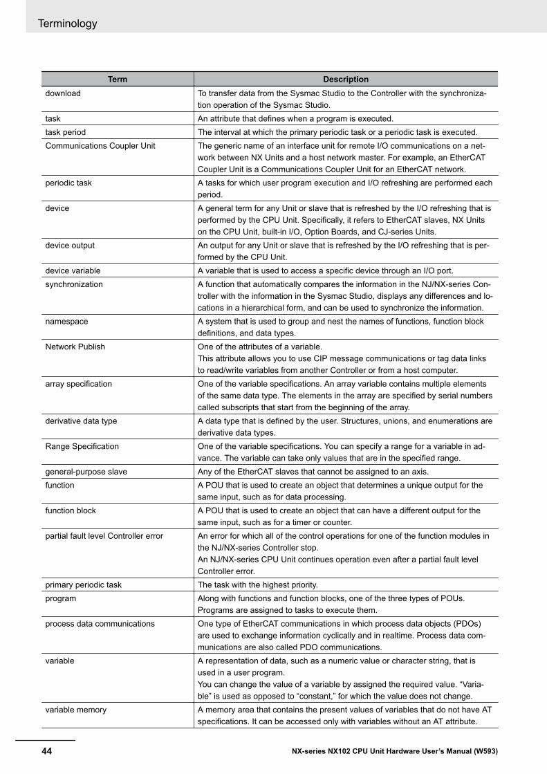
Term Descriptiondownload To transfer data from the Sysmac Studio to the Controller with the synchroniza-
tion operation of the Sysmac Studio.task An attribute that defines when a program is executed.task period The interval at which the primary periodic task or a periodic task is executed.Communications Coupler Unit The generic name of an interface unit for remote I/O communications on a net-
work between NX Units and a host network master. For example, an EtherCATCoupler Unit is a Communications Coupler Unit for an EtherCAT network.
periodic task A tasks for which user program execution and I/O refreshing are performed eachperiod.
device A general term for any Unit or slave that is refreshed by the I/O refreshing that isperformed by the CPU Unit. Specifically, it refers to EtherCAT slaves, NX Unitson the CPU Unit, built-in I/O, Option Boards, and CJ-series Units.
device output An output for any Unit or slave that is refreshed by the I/O refreshing that is per-formed by the CPU Unit.
device variable A variable that is used to access a specific device through an I/O port.synchronization A function that automatically compares the information in the NJ/NX-series Con-
troller with the information in the Sysmac Studio, displays any differences and lo-cations in a hierarchical form, and can be used to synchronize the information.
namespace A system that is used to group and nest the names of functions, function blockdefinitions, and data types.
Network Publish One of the attributes of a variable.This attribute allows you to use CIP message communications or tag data linksto read/write variables from another Controller or from a host computer.
array specification One of the variable specifications. An array variable contains multiple elementsof the same data type. The elements in the array are specified by serial numberscalled subscripts that start from the beginning of the array.
derivative data type A data type that is defined by the user. Structures, unions, and enumerations arederivative data types.
Range Specification One of the variable specifications. You can specify a range for a variable in ad-vance. The variable can take only values that are in the specified range.
general-purpose slave Any of the EtherCAT slaves that cannot be assigned to an axis.function A POU that is used to create an object that determines a unique output for the
same input, such as for data processing.function block A POU that is used to create an object that can have a different output for the
same input, such as for a timer or counter.partial fault level Controller error An error for which all of the control operations for one of the function modules in
the NJ/NX-series Controller stop.An NJ/NX-series CPU Unit continues operation even after a partial fault levelController error.
primary periodic task The task with the highest priority.program Along with functions and function blocks, one of the three types of POUs.
Programs are assigned to tasks to execute them.process data communications One type of EtherCAT communications in which process data objects (PDOs)
are used to exchange information cyclically and in realtime. Process data com-munications are also called PDO communications.
variable A representation of data, such as a numeric value or character string, that isused in a user program.You can change the value of a variable by assigned the required value. “Varia-ble” is used as opposed to “constant,” for which the value does not change.
variable memory A memory area that contains the present values of variables that do not have ATspecifications. It can be accessed only with variables without an AT attribute.
Terminology
44 NX-series NX102 CPU Unit Hardware User’s Manual (W593)

Term DescriptionRetain One of the attributes of a variable. The values of variables with a Retain attribute
are held at the following times. (Variables without a Retain attribute are set totheir initial values.)• When power is turned ON after a power interruption• When the CPU Unit changes to RUN mode• When you specify to not initialize the values when the user program is trans-
ferredinstruction The smallest unit of the processing elements that are provided by OMRON for
use in POU algorithms.There are ladder diagram instructions (program inputs and outputs), function in-structions, function block instructions, and ST statements.
main memory The memory inside the CPU Unit that is used by the CPU Unit to execute the OSand user program.
Motion Control Function Module One of the function modules. The MC Function Module performs motion controlbased on commands from the motion control instructions that are executed inthe user program.
motion control instruction A function block instruction that executes motion control.The Motion Control Function Module supports instructions that are based onfunction blocks for PLCopen® motion control as well as instructions developedspecifically for the Motion Control Function Module.
user-defined event One of the events in the NJ/NX-series System. These events are defined by theuser. “User-defined events” is a generic term for user-defined errors and user-defined information.
user-defined variable A variable for which all of the attributes are defined by the user and can bechanged by the user.
user program All of the programs in one project.Unit A device that mounts to the CPU Rack or an Expansion Rack.Unit configuration The configuration information for the Units that are set on the Sysmac Studio.
This information tells what Unit models are connected to the CPU Unit andwhere they are connected.
literal A constant expression that is used in a user program.enumeration One of the derivative data types. This data type takes one item from a prepared
name list of enumerators as its value.enumerator One of the values that an enumeration can take expressed as a character string.
The value of an enumeration is one of the enumerators.local variable A variable that can be accessed only from inside the POU in which it is defined.
“Local variable” is used as opposed to “global variable.”Local variables include internal variables, input variables, output variables, in-outvariables, and external variables.
Terminology
45NX-series NX102 CPU Unit Hardware User’s Manual (W593)
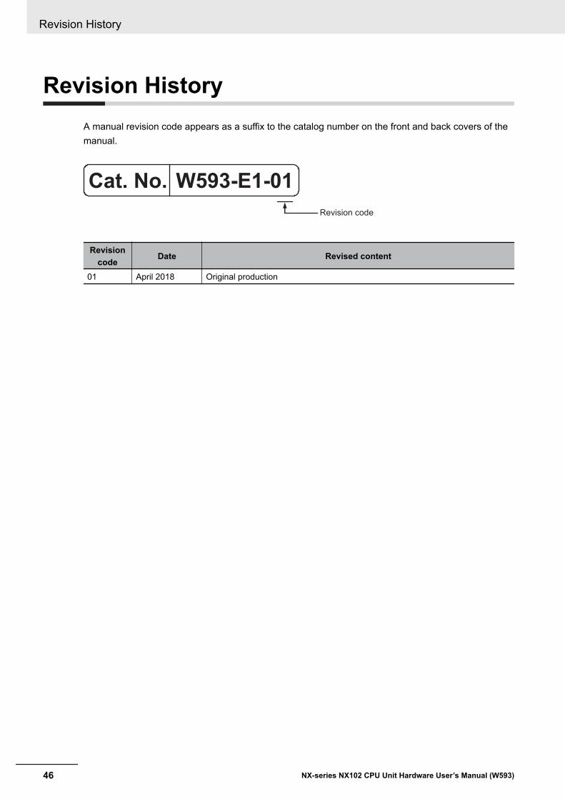
Revision HistoryA manual revision code appears as a suffix to the catalog number on the front and back covers of themanual.
W593-E1-01
Revision code
Cat. No.
Revisioncode Date Revised content
01 April 2018 Original production
Revision History
46 NX-series NX102 CPU Unit Hardware User’s Manual (W593)
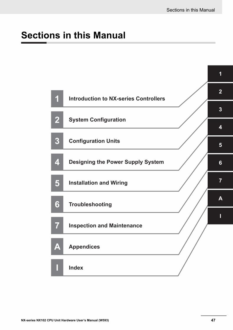
Sections in this Manual
1
2
3
4
5
1
2
3
4
5
A
Introduction to NX-series Controllers
System Configuration
Configuration Units
Designing the Power Supply System
Installation and Wiring
A
6
7
Appendices
6
7
Troubleshooting
Inspection and Maintenance
I
I
Index
Sections in this Manual
47NX-series NX102 CPU Unit Hardware User’s Manual (W593)

Sections in this Manual
48 NX-series NX102 CPU Unit Hardware User’s Manual (W593)
1Introduction to NX-series Control-lers
This section describes the features, basic system configuration, specifications, andoverall operating procedure of an NX-series Controller NX102.
1-1 The NX-series Controller ............................................................................. 1 - 21-1-1 Features........................................................................................................ 1 - 31-1-2 Introduction to the System Configurations.................................................... 1 - 6
1-2 Specifications............................................................................................... 1 - 91-3 Overall Operating Procedure for the CPU Unit ....................................... 1 - 14
1-3-1 Overall Procedure....................................................................................... 1 - 141-3-2 Procedure Details ....................................................................................... 1 - 15
1 - 1NX-series NX102 CPU Unit Hardware User’s Manual (W593)
1
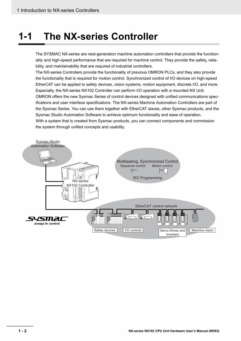
1-1 The NX-series ControllerThe SYSMAC NX-series are next-generation machine automation controllers that provide the function-ality and high-speed performance that are required for machine control. They provide the safety, relia-bility, and maintainability that are required of industrial controllers.The NX-series Controllers provide the functionality of previous OMRON PLCs, and they also providethe functionality that is required for motion control. Synchronized control of I/O devices on high-speedEtherCAT can be applied to safety devices, vision systems, motion equipment, discrete I/O, and more.Especially, the NX-series NX102 Controller can perform I/O operation with a mounted NX Unit.OMRON offers the new Sysmac Series of control devices designed with unified communications spec-ifications and user interface specifications. The NX-series Machine Automation Controllers are part ofthe Sysmac Series. You can use them together with EtherCAT slaves, other Sysmac products, and theSysmac Studio Automation Software to achieve optimum functionality and ease of operation.With a system that is created from Sysmac products, you can connect components and commissionthe system through unified concepts and usability.
Sysmac Studio
Automation Software
Multitasking, Synchronized ControlSequence control Motion control
IEC Programming
EtherCAT control network
Safety devices I/O controls Servo Drives and
Inverters
Machine vision
NX-series
NX102 Controller
1 Introduction to NX-series Controllers
1 - 2 NX-series NX102 CPU Unit Hardware User’s Manual (W593)
1-1-1 Features
Hardware Features
l Standard-feature EtherCAT Control Network SupportAll CPU Units provide an EtherCAT master port for EtherCAT communications.EtherCAT is an advanced industrial network system that achieves faster, more-efficient communi-cations. It is based on Ethernet. Each node achieves a short fixed communications cycle time bytransmitting Ethernet frames at high speed.The standard-feature EtherCAT control network allows you to connect all of the devices requiredfor machine control (e.g., I/O systems, Servo Drives, Inverters, and machine vision) to the samenetwork.
l Support for EtherCAT Slave TerminalsYou can use EtherCAT Slave Terminals to save space. You can also flexibly build systems with thewide variety of NX Units.
l Achieving a Safety SubsystemYou can use NX-series Safety Control Units to integrate safety controls in sequence and motioncontrol systems.
l Standard-feature EtherNet/IP Communications PortsAll CPU Units provide two EtherNet/IP ports for EtherNet/IP communications.EtherNet/IP is a multi-vendor industrial network that uses Ethernet. You can use it for networks be-tween Controllers or as a field network. The use of standard Ethernet technology allows you to con-nect to many different types of general-purpose Ethernet devices. Moreover, with two EtherNet/IPports these CPU Units enable the integrated control of two separate control systems, for example,one of the host information control system for communications between Controllers and the otherfor a lower-level field network control system.
l NX-series Units ConnectableThe CPU Unit can be connected with up to 32 NX Units including NX-series Digital I/O Units, Ana-log I/O Units, and other I/O Units.
l Battery-free OperationThe following data (other than the clock data) is retained in the built-in non-volatile memory.• User program• Set values• Variables retained during power interruption• Event logs
The retention period for the clock data is limited*1.When the clock data is not needed or the equipment’s power OFF time is shorter than the clockdata retention period, the battery-free operation is possible and man-hours for battery replacementcan be reduced.
1 Introduction to NX-series Controllers
1 - 3NX-series NX102 CPU Unit Hardware User’s Manual (W593)
1-1 The NX-series C
ontroller
1
1-1-1 Features
If you turn OFF the power supply to the equipment for a longer period of time than the clock dataretention period, mount a battery which is sold separately.*1. Approximately 10 days at an ambient temperature of 40°C. Refer to 3-1-5 Battery on page 3 - 11 for de-
tail.
l Standard-feature SD Memory Card SlotYou can access an SD Memory Card that is mounted in the CPU Unit from the user program.
l Highly Reliable HardwareThe NX-series Controllers provide the hardware reliability and RAS functions that you expect of aPLC.
Software Features
l Integrated Sequence Control and Motion ControlAn NX-series CPU Unit can perform both sequence control and motion control. You can simultane-ously achieve both sequence control and multi-axes synchronized control. Sequence control, mo-tion control, and I/O refreshing are all executed in the same control period.The same control period is also used for the process data communications cycle for EtherCAT. Thisenables precise sequence and motion control in a fixed period with very little deviation.
l Programming Languages Based on the IEC 61131-3 International StandardThe NJ-series Controllers support language specifications that are based on IEC 61131-3. Tothese, OMRON has added our own improvements. Motion control instructions that are based on
PLCopen® standards and an instruction set (POUs) that follows IEC rules are provided.
l Programming with Variables to Eliminate Worrying about the Memory MapYou access all data through variables in the same way as for the advanced programming languag-es that are used on computers. Memory in the CPU Unit is automatically assigned to the variablesthat you create so that you do not have to remember the physical addresses.
l A Wealth of Security FeaturesThe many security features of the NX-series Controllers include operation authority settings and re-striction of program execution with IDs.
l Complete Controller MonitoringThe CPU Unit monitors events in all parts of the Controller, including mounted NX Units and Ether-CAT slaves.Troubleshooting information for errors is displayed on the Sysmac Studio or on an NS-series PT.Events are also recorded in logs.
l Sysmac Studio Automation SoftwareThe Sysmac Studio provides an integrated development environment that covers not only the Con-troller, but also covers peripheral devices and devices on EtherCAT. You can use consistent proce-dures for all devices regardless of the differences in the devices. The Sysmac Studio supports all
1 Introduction to NX-series Controllers
1 - 4 NX-series NX102 CPU Unit Hardware User’s Manual (W593)
phases of Controller application, from designing through debugging, simulations, commissioning,and changes during operation.
l A Wealth of Simulation FeaturesThe many simulation features include execution, debugging, and task execution time estimates ona virtual controller.
1 Introduction to NX-series Controllers
1 - 5NX-series NX102 CPU Unit Hardware User’s Manual (W593)
1-1 The NX-series C
ontroller
1
1-1-1 Features
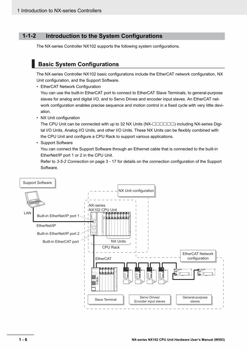
1-1-2 Introduction to the System ConfigurationsThe NX-series Controller NX102 supports the following system configurations.
Basic System ConfigurationsThe NX-series Controller NX102 basic configurations include the EtherCAT network configuration, NXUnit configuration, and the Support Software.• EtherCAT Network Configuration
You can use the built-in EtherCAT port to connect to EtherCAT Slave Terminals, to general-purposeslaves for analog and digital I/O, and to Servo Drives and encoder input slaves. An EtherCAT net-work configuration enables precise sequence and motion control in a fixed cycle with very little devi-ation.
• NX Unit configurationThe CPU Unit can be connected with up to 32 NX Units (NX-££££££) including NX-series Digi-tal I/O Units, Analog I/O Units, and other I/O Units. These NX Units can be flexibly combined withthe CPU Unit and configure a CPU Rack to support various applications.
• Support SoftwareYou can connect the Support Software through an Ethernet cable that is connected to the built-inEtherNet/IP port 1 or 2 in the CPU Unit.Refer to 3-5-2 Connection on page 3 - 17 for details on the connection configuration of the SupportSoftware.
EtherNet/IP
LAN
Slave TerminalServo Drives/
Encoder input slaves
General-purpose
slaves
Support Software
EtherCAT
CPU Rack
NX Units
EtherCAT Network
configuration
Built-in EtherNet/IP port 1
Built-in EtherNet/IP port 2
Built-in EtherCAT port
NX Unit configuration
NX-series
NX102 CPU Unit
1 Introduction to NX-series Controllers
1 - 6 NX-series NX102 CPU Unit Hardware User’s Manual (W593)

Network Configurations• Host computers, HMIs, and other NJ/NX-series Controllers or field network devices are connected
to the two built-in EtherNet/IP ports.• A DeviceNet network is connected to a CJ-series DeviceNet Unit mounted to the NJ-series CPU
Unit.• A serial communications network is connected to the following Units.
NX-series Communications Interface UnitCJ-series Serial Communications Unit
EtherCAT Slave Terminal
Vision Systems
SysmacStudio
EtherNet/IP
DeviceNet
EtherCAT
CompoNet
REMOTE TERMINAL
0 1 2 3 4 5 6 7 8 9 10 11 12 13 14 15
OUT
CRT1-OD16
MS NS WORD NODE ADR
REMOTE TERMINAL
0 1 2 3 4 5 6 7 8 9 10 11 12 13 14 15
OUT
CRT1-OD16
MS NS WORD NODE ADR
REMOTE TERMINAL
0 1 2 3 4 5 6 7 8 9 10 11 12 13 14 15
OUT
CRT1-OD16
MS NS WORD NODE ADR
EtherNet/IP
Information
Level
Built-in EtherNet/IP port 1
Built-in EtherNet/IP port 2
Built-in EtherCAT port
Built-in EtherNet/IP ports
CompoNet Master Unit
CompoNet slaves
DeviceNet slaves
DeviceNet Unit
NJ-series CPU Unit
Field Level
NX-series NX102 CPU Unit
Serial Communications Unit
RS-232C, RS-422A/485
RFID system Robots
Servo Drives
General-purpose slaves
Serial communications devices
NX-series Communications Interface Unit
General-purpose components or OMRON components
Serial communications devices
General-purpose components or OMRON components
NJ/NX-series CPU Unit
Programmable terminal
FA Wireless LAN Unit
FA Communications
Software
Refer to the NJ/NX-series CPU Unit Software User’s Manual (Cat. No. W501) for details on the net-work configuration.
1 Introduction to NX-series Controllers
1 - 7NX-series NX102 CPU Unit Hardware User’s Manual (W593)
1-1 The NX-series C
ontroller
1
1-1-2 Introduction to the System C
onfigurations
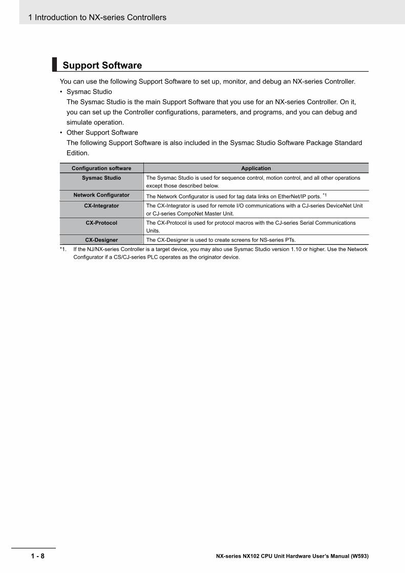
Support SoftwareYou can use the following Support Software to set up, monitor, and debug an NX-series Controller.• Sysmac Studio
The Sysmac Studio is the main Support Software that you use for an NX-series Controller. On it,you can set up the Controller configurations, parameters, and programs, and you can debug andsimulate operation.
• Other Support SoftwareThe following Support Software is also included in the Sysmac Studio Software Package StandardEdition.
Configuration software ApplicationSysmac Studio The Sysmac Studio is used for sequence control, motion control, and all other operations
except those described below.Network Configurator The Network Configurator is used for tag data links on EtherNet/IP ports. *1
CX-Integrator The CX-Integrator is used for remote I/O communications with a CJ-series DeviceNet Unitor CJ-series CompoNet Master Unit.
CX-Protocol The CX-Protocol is used for protocol macros with the CJ-series Serial CommunicationsUnits.
CX-Designer The CX-Designer is used to create screens for NS-series PTs.*1. If the NJ/NX-series Controller is a target device, you may also use Sysmac Studio version 1.10 or higher. Use the Network
Configurator if a CS/CJ-series PLC operates as the originator device.
1 Introduction to NX-series Controllers
1 - 8 NX-series NX102 CPU Unit Hardware User’s Manual (W593)
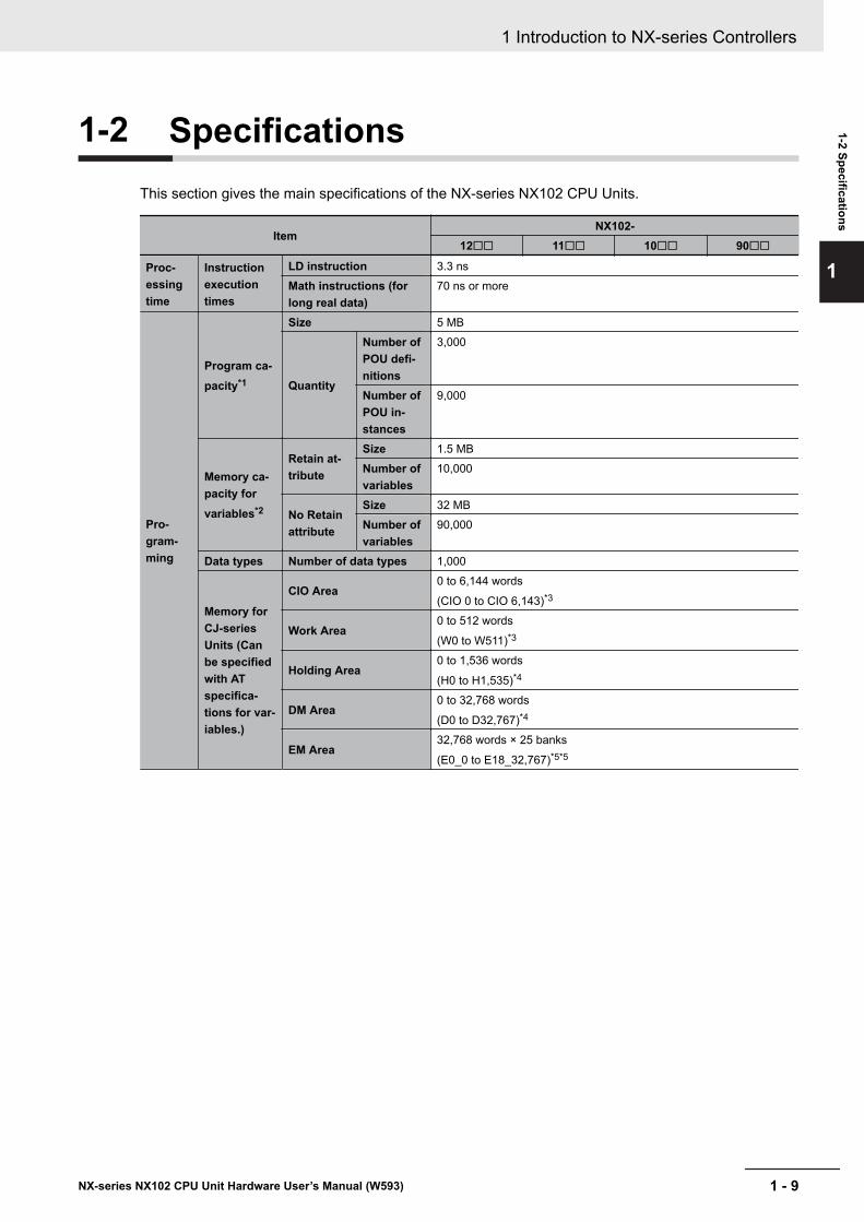
1-2 SpecificationsThis section gives the main specifications of the NX-series NX102 CPU Units.
ItemNX102-
12££ 11££ 10££ 90££
Proc-essingtime
Instructionexecutiontimes
LD instruction 3.3 nsMath instructions (forlong real data)
70 ns or more
Pro-gram-ming
Program ca-pacity*1
Size 5 MB
Quantity
Number ofPOU defi-nitions
3,000
Number ofPOU in-stances
9,000
Memory ca-pacity forvariables*2
Retain at-tribute
Size 1.5 MBNumber ofvariables
10,000
No Retainattribute
Size 32 MBNumber ofvariables
90,000
Data types Number of data types 1,000
Memory forCJ-seriesUnits (Canbe specifiedwith ATspecifica-tions for var-iables.)
CIO Area0 to 6,144 words
(CIO 0 to CIO 6,143)*3
Work Area0 to 512 words
(W0 to W511)*3
Holding Area0 to 1,536 words
(H0 to H1,535)*4
DM Area0 to 32,768 words
(D0 to D32,767)*4
EM Area32,768 words × 25 banks
(E0_0 to E18_32,767)*5*5
1 Introduction to NX-series Controllers
1 - 9NX-series NX102 CPU Unit Hardware User’s Manual (W593)
1-2 Specifications
1
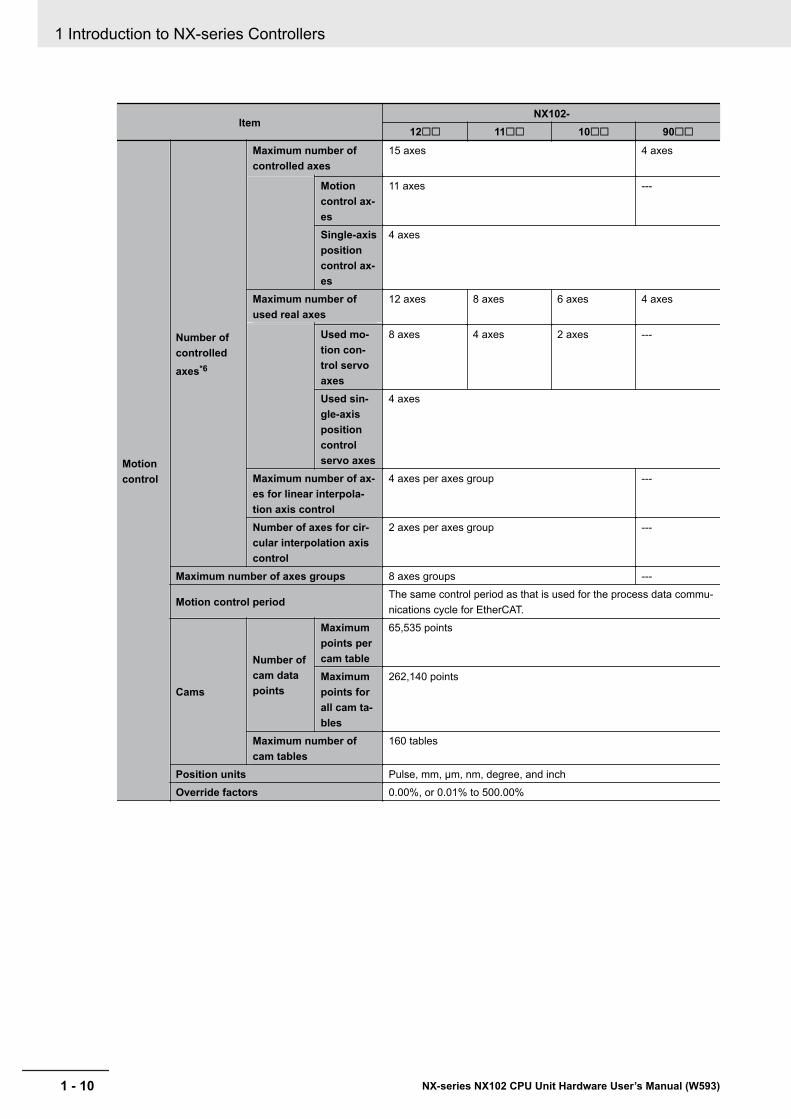
ItemNX102-
12££ 11££ 10££ 90££
Motioncontrol
Number ofcontrolledaxes*6
Maximum number ofcontrolled axes
15 axes 4 axes
Motioncontrol ax-es
11 axes ---
Single-axispositioncontrol ax-es
4 axes
Maximum number ofused real axes
12 axes 8 axes 6 axes 4 axes
Used mo-tion con-trol servoaxes
8 axes 4 axes 2 axes ---
Used sin-gle-axispositioncontrolservo axes
4 axes
Maximum number of ax-es for linear interpola-tion axis control
4 axes per axes group ---
Number of axes for cir-cular interpolation axiscontrol
2 axes per axes group ---
Maximum number of axes groups 8 axes groups ---
Motion control periodThe same control period as that is used for the process data commu-nications cycle for EtherCAT.
Cams
Number ofcam datapoints
Maximumpoints percam table
65,535 points
Maximumpoints forall cam ta-bles
262,140 points
Maximum number ofcam tables
160 tables
Position units Pulse, mm, μm, nm, degree, and inchOverride factors 0.00%, or 0.01% to 500.00%
1 Introduction to NX-series Controllers
1 - 10 NX-series NX102 CPU Unit Hardware User’s Manual (W593)
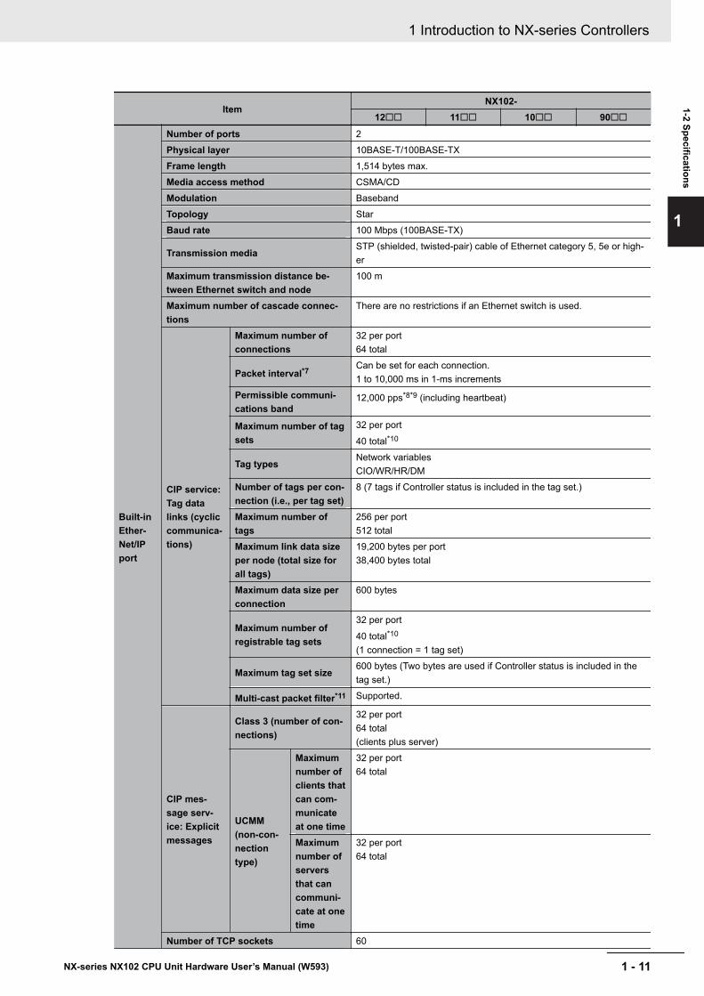
ItemNX102-
12££ 11££ 10££ 90££
Built-inEther-Net/IPport
Number of ports 2Physical layer 10BASE-T/100BASE-TXFrame length 1,514 bytes max.Media access method CSMA/CDModulation BasebandTopology StarBaud rate 100 Mbps (100BASE-TX)
Transmission mediaSTP (shielded, twisted-pair) cable of Ethernet category 5, 5e or high-er
Maximum transmission distance be-tween Ethernet switch and node
100 m
Maximum number of cascade connec-tions
There are no restrictions if an Ethernet switch is used.
CIP service:Tag datalinks (cycliccommunica-tions)
Maximum number ofconnections
32 per port64 total
Packet interval*7Can be set for each connection.1 to 10,000 ms in 1-ms increments
Permissible communi-cations band
12,000 pps*8*9 (including heartbeat)
Maximum number of tagsets
32 per port
40 total*10
Tag typesNetwork variablesCIO/WR/HR/DM
Number of tags per con-nection (i.e., per tag set)
8 (7 tags if Controller status is included in the tag set.)
Maximum number oftags
256 per port512 total
Maximum link data sizeper node (total size forall tags)
19,200 bytes per port38,400 bytes total
Maximum data size perconnection
600 bytes
Maximum number ofregistrable tag sets
32 per port
40 total*10
(1 connection = 1 tag set)
Maximum tag set size600 bytes (Two bytes are used if Controller status is included in thetag set.)
Multi-cast packet filter*11 Supported.
CIP mes-sage serv-ice: Explicitmessages
Class 3 (number of con-nections)
32 per port64 total(clients plus server)
UCMM(non-con-nectiontype)
Maximumnumber ofclients thatcan com-municateat one time
32 per port64 total
Maximumnumber ofserversthat cancommuni-cate at onetime
32 per port64 total
Number of TCP sockets 60
1 Introduction to NX-series Controllers
1 - 11NX-series NX102 CPU Unit Hardware User’s Manual (W593)
1-2 Specifications
1
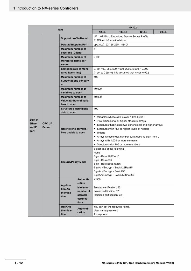
ItemNX102-
12££ 11££ 10££ 90££
Built-inEther-Net/IPport
OPC UAServer
Support profile/ModelUA 1.02 Micro Embedded Device Server ProfilePLCOpen Information Model
Default Endpoint/Port opc.tcp://192.168.250.1:4840/Maximum number ofsessions (Client)
5
Maximum number ofMonitored Items perserver
2,000
Sampling rate of Moni-tored Items (ms)
0, 50, 100, 250, 500, 1000, 2000, 5,000, 10,000(If set to 0 (zero), it is assumed that is set to 50.)
Maximum number ofSubscriptions per serv-er
100
Maximum number ofvariables to open
10,000
Maximum number ofValue attribute of varia-bles to open
10,000
Structure’s definitionsable to open
100
Restrictions on varia-bles unable to open
• Variables whose size is over 1,024 bytes• Two-dimensional or higher structure arrays• Structures that include two-dimensional and higher arrays• Structures with four or higher levels of nesting• Unions• Arrays whose index number suffix does no start from 0• Arrays with 1,024 or more elements• Structures with 100 or more members
SecurityPolicy/Mode
Select one of the following.NoneSign - Basic128Rsa15Sign - Basic256Sign - Basic256Sha256SignAndEncrypt - Basic128Rsa15SignAndEncrypt - Basic256SignAndEncrypt - Basic256Sha256
Applica-tion Au-thentica-tion
Authenti-cation
X.509
Maximumnumber ofstorablecertifica-tions
Trusted certification: 32Issuer certification: 32Rejected certification: 32
User Au-thentica-tion
Authenti-cation
You can set the following items.User name/passwordAnonymous
1 Introduction to NX-series Controllers
1 - 12 NX-series NX102 CPU Unit Hardware User’s Manual (W593)
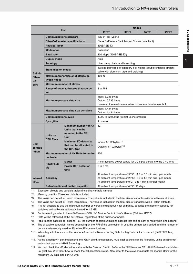
ItemNX102-
12££ 11££ 10££ 90££
Built-inEther-CATport
Communications standard IEC 61158 Type12EtherCAT master specifications Class B (Feature Pack Motion Control compliant)Physical layer 100BASE-TXModulation BasebandBaud rate 100 Mbps (100BASE-TX)Duplex mode AutoTopology Line, daisy chain, and branching
Transmission mediaTwisted-pair cable of category 5 or higher (double-shielded straightcable with aluminum tape and braiding)
Maximum transmission distance be-tween nodes
100 m
Maximum number of slaves 64Range of node addresses that can beset
1 to 192
Maximum process data sizeInput: 5,736 bytesOutput: 5,736 bytesHowever, the maximum number of process data frames is 4.
Maximum process data size per slaveInput: 1,434 bytesOutput: 1,434 bytes
Communications cycle 1,000 to 32,000 µs (in 250-µs increments)Sync jitter 1 μs max.
Unitconfigu-ration
Units onCPU Rack
Maximum number of NXUnits that can bemounted to the CPUUnit
32
Maximum I/O data sizethat can be allocated inthe CPU Unit
Inputs: 8,192 bytes*12
Outputs: 8,192 bytes*12
Maximum number of NX Units for entirecontroller
400
Power sup-ply
Model A non-isolated power supply for DC input is built into the CPU Unit.Power OFF detectiontime
2 to 8 ms
Internalclock
AccuracyAt ambient temperature of 55°C: -3.5 to 0.5 min error per monthAt ambient temperature of 25°C: -1.5 to 1.5 min error per monthAt ambient temperature of 0°C: -3 to 1 min error per month
Retention time of built-in capacitor At ambient temperature of 40°C: 10 days*1. Execution objects and variable tables (including variable names)*2. Memory used for CJ-series Units is included.*3. The value can be set in 1-word increments. The value is included in the total size of variables without a Retain attribute.*4. The value can be set in 1-word increments. The value is included in the total size of variables with a Retain attribute.*5. It is not possible to use the maximum number of words simultaneously for all banks, because the memory capacity for
variables with a Retain attribute is limited to 1.5 MB.*6. For terminology, refer to the NJ/NX-series CPU Unit Motion Control User’s Manual (Cat. No. W507).*7. Data will be refreshed at the set interval, regardless of the number of nodes.*8. “pps” means packets per second, i.e., the number of communications packets that can be sent or received in one second.*9. The allowable bandwidth varies depending on the RPI of the connection in use, the primary task period, and the number of
ports simultaneously used for EtherNet/IP communications.*10. When tag sets that exceed the total of 40 are set, a Number of Tag Sets for Tag Data Links Exceeded (840E0000 hex)
occurs.*11. As the EtherNet/IP port implements the IGMP client, unnecessary multi-cast packets can be filtered by using an Ethernet
switch that supports IGMP Snooping.*12. You can check the I/O allocation status with the Sysmac Studio. Refer to the NJ/NX-series CPU Unit Software User’s Man-
ual (Cat. No. W501) for how to check the I/O allocation status. Also, refer to the relevant manuals for specific Units for themaximum I/O data size per NX Unit.
1 Introduction to NX-series Controllers
1 - 13NX-series NX102 CPU Unit Hardware User’s Manual (W593)
1-2 Specifications
1
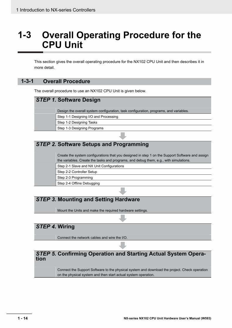
1-3 Overall Operating Procedure for theCPU Unit
This section gives the overall operating procedure for the NX102 CPU Unit and then describes it inmore detail.
1-3-1 Overall ProcedureThe overall procedure to use an NX102 CPU Unit is given below.
STEP 1. Software Design
Design the overall system configuration, task configuration, programs, and variables.Step 1-1 Designing I/O and ProcessingStep 1-2 Designing TasksStep 1-3 Designing Programs
STEP 2. Software Setups and Programming
Create the system configurations that you designed in step 1 on the Support Software and assignthe variables. Create the tasks and programs, and debug them, e.g., with simulations.Step 2-1 Slave and NX Unit ConfigurationsStep 2-2 Controller SetupStep 2-3 ProgrammingStep 2-4 Offline Debugging
STEP 3. Mounting and Setting Hardware
Mount the Units and make the required hardware settings.
STEP 4. Wiring
Connect the network cables and wire the I/O.
STEP 5. Confirming Operation and Starting Actual System Opera-tion
Connect the Support Software to the physical system and download the project. Check operationon the physical system and then start actual system operation.
1 Introduction to NX-series Controllers
1 - 14 NX-series NX102 CPU Unit Hardware User’s Manual (W593)
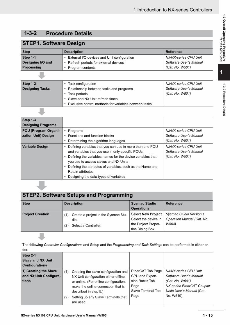
1-3-2 Procedure Details
STEP1. Software DesignStep Description ReferenceStep 1-1Designing I/O andProcessing
• External I/O devices and Unit configuration• Refresh periods for external devices• Program contents
NJ/NX-series CPU UnitSoftware User’s Manual(Cat. No. W501)
Step 1-2Designing Tasks
• Task configuration• Relationship between tasks and programs• Task periods• Slave and NX Unit refresh times• Exclusive control methods for variables between tasks
NJ/NX-series CPU UnitSoftware User’s Manual(Cat. No. W501)
Step 1-3Designing ProgramsPOU (Program Organi-zation Unit) Design
• Programs• Functions and function blocks• Determining the algorithm languages
NJ/NX-series CPU UnitSoftware User’s Manual(Cat. No. W501)
Variable Design • Defining variables that you can use in more than one POUand variables that you use in only specific POUs
• Defining the variables names for the device variables thatyou use to access slaves and NX Units
• Defining the attributes of variables, such as the Name andRetain attributes
• Designing the data types of variables
NJ/NX-series CPU UnitSoftware User’s Manual(Cat. No. W501)
STEP2. Software Setups and ProgrammingStep Description Sysmac Studio
OperationsReference
Project Creation (1) Create a project in the Sysmac Stu-dio.
(2) Select a Controller.
Select New ProjectSelect the device inthe Project Proper-ties Dialog Box
Sysmac Studio Version 1Operation Manual (Cat. No.W504)
The following Controller Configurations and Setup and the Programming and Task Settings can be performed in either or-der.Step 2-1Slave and NX UnitConfigurations1) Creating the Slaveand NX Unit Configura-tions
(1) Creating the slave configuration andNX Unit configuration either offlineor online. (For online configuration,make the online connection that isdescribed in step 5.)
(2) Setting up any Slave Terminals thatare used.
EtherCAT Tab PageCPU and Expan-sion Racks TabPageSlave Terminal TabPage
NJ/NX-series CPU UnitSoftware User’s Manual(Cat. No. W501)NX-series EtherCAT CouplerUnits User’s Manual (Cat.No. W519)
1 Introduction to NX-series Controllers
1 - 15NX-series NX102 CPU Unit Hardware User’s Manual (W593)
1-3 Overall O
perating Procedurefor the C
PU U
nit
1
1-3-2 Procedure Details
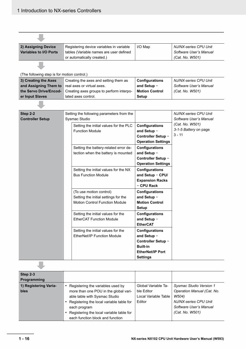
2) Assigning DeviceVariables to I/O Ports
Registering device variables in variabletables (Variable names are user definedor automatically created.)
I/O Map NJ/NX-series CPU UnitSoftware User’s Manual(Cat. No. W501)
(The following step is for motion control.)3) Creating the Axesand Assigning Them tothe Servo Drive/Encod-er Input Slaves
Creating the axes and setting them asreal axes or virtual axes.Creating axes groups to perform interpo-lated axes control.
Configurationsand Setup −Motion ControlSetup
NJ/NX-series CPU UnitSoftware User’s Manual(Cat. No. W501)
Step 2-2Controller Setup
Setting the following parameters from theSysmac Studio
NJ/NX-series CPU UnitSoftware User’s Manual(Cat. No. W501)3-1-5 Battery on page3 - 11
Setting the initial values for the PLCFunction Module
Configurationsand Setup −Controller Setup −Operation Settings
Setting the battery-related error de-tection when the battery is mounted
Configurationsand Setup −Controller Setup −Operation Settings
Setting the initial values for the NXBus Function Module
Configurationsand Setup − CPU/Expansion Racks− CPU Rack
(To use motion control)Setting the initial settings for theMotion Control Function Module
Configurationsand Setup −Motion ControlSetup
Setting the initial values for theEtherCAT Function Module
Configurationsand Setup −EtherCAT
Setting the initial values for theEtherNet/IP Function Module
Configurationsand Setup −Controller Setup −Built-inEtherNet/IP PortSettings
Step 2-3Programming1) Registering Varia-bles
• Registering the variables used bymore than one POU in the global vari-able table with Sysmac Studio
• Registering the local variable table foreach program
• Registering the local variable table foreach function block and function
Global Variable Ta-ble EditorLocal Variable TableEditor
Sysmac Studio Version 1Operation Manual (Cat. No.W504)NJ/NX-series CPU UnitSoftware User’s Manual(Cat. No. W501)
1 Introduction to NX-series Controllers
1 - 16 NX-series NX102 CPU Unit Hardware User’s Manual (W593)
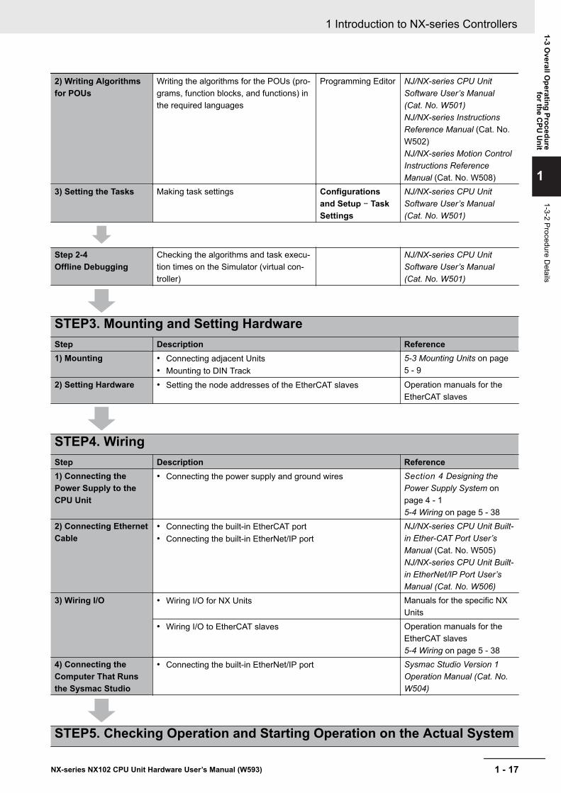
2) Writing Algorithmsfor POUs
Writing the algorithms for the POUs (pro-grams, function blocks, and functions) inthe required languages
Programming Editor NJ/NX-series CPU UnitSoftware User’s Manual(Cat. No. W501)NJ/NX-series InstructionsReference Manual (Cat. No.W502)NJ/NX-series Motion ControlInstructions ReferenceManual (Cat. No. W508)
3) Setting the Tasks Making task settings Configurationsand Setup − TaskSettings
NJ/NX-series CPU UnitSoftware User’s Manual(Cat. No. W501)
Step 2-4Offline Debugging
Checking the algorithms and task execu-tion times on the Simulator (virtual con-troller)
NJ/NX-series CPU UnitSoftware User’s Manual(Cat. No. W501)
STEP3. Mounting and Setting HardwareStep Description Reference1) Mounting • Connecting adjacent Units
• Mounting to DIN Track5-3 Mounting Units on page5 - 9
2) Setting Hardware • Setting the node addresses of the EtherCAT slaves Operation manuals for theEtherCAT slaves
STEP4. WiringStep Description Reference1) Connecting thePower Supply to theCPU Unit
• Connecting the power supply and ground wires Section 4 Designing thePower Supply System onpage 4 - 15-4 Wiring on page 5 - 38
2) Connecting EthernetCable
• Connecting the built-in EtherCAT port• Connecting the built-in EtherNet/IP port
NJ/NX-series CPU Unit Built-in Ether-CAT Port User’sManual (Cat. No. W505)NJ/NX-series CPU Unit Built-in EtherNet/IP Port User’sManual (Cat. No. W506)
3) Wiring I/O • Wiring I/O for NX Units Manuals for the specific NXUnits
• Wiring I/O to EtherCAT slaves Operation manuals for theEtherCAT slaves5-4 Wiring on page 5 - 38
4) Connecting theComputer That Runsthe Sysmac Studio
• Connecting the built-in EtherNet/IP port Sysmac Studio Version 1Operation Manual (Cat. No.W504)
STEP5. Checking Operation and Starting Operation on the Actual System
1 Introduction to NX-series Controllers
1 - 17NX-series NX102 CPU Unit Hardware User’s Manual (W593)
1-3 Overall O
perating Procedurefor the C
PU U
nit
1
1-3-2 Procedure Details
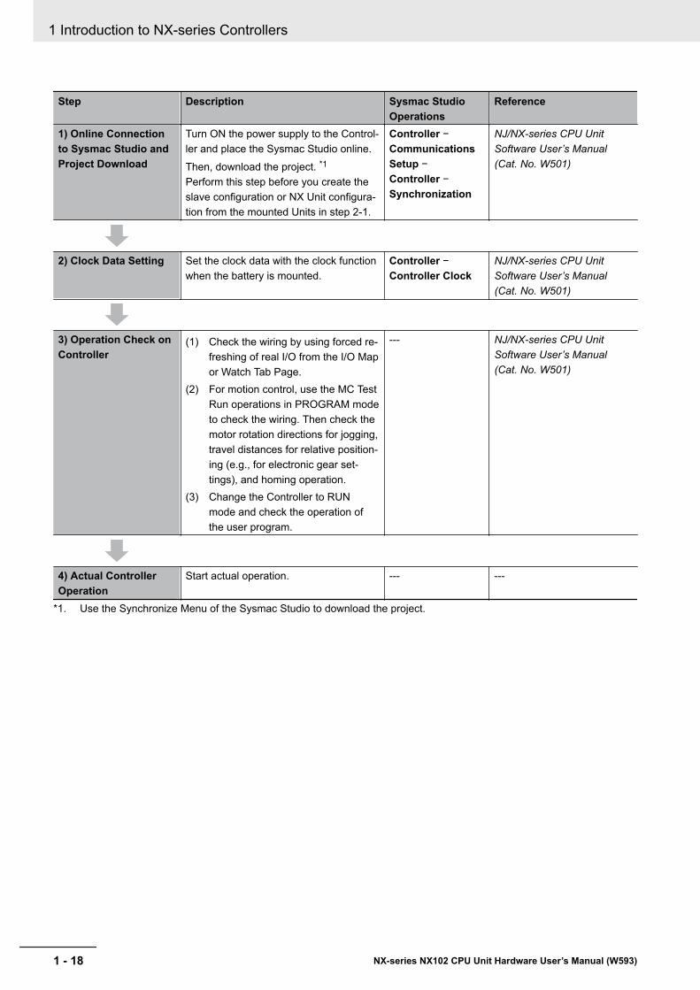
Step Description Sysmac StudioOperations
Reference
1) Online Connectionto Sysmac Studio andProject Download
Turn ON the power supply to the Control-ler and place the Sysmac Studio online.Then, download the project. *1
Perform this step before you create theslave configuration or NX Unit configura-tion from the mounted Units in step 2-1.
Controller −CommunicationsSetup −Controller −Synchronization
NJ/NX-series CPU UnitSoftware User’s Manual(Cat. No. W501)
2) Clock Data Setting Set the clock data with the clock functionwhen the battery is mounted.
Controller −Controller Clock
NJ/NX-series CPU UnitSoftware User’s Manual(Cat. No. W501)
3) Operation Check onController
(1) Check the wiring by using forced re-freshing of real I/O from the I/O Mapor Watch Tab Page.
(2) For motion control, use the MC TestRun operations in PROGRAM modeto check the wiring. Then check themotor rotation directions for jogging,travel distances for relative position-ing (e.g., for electronic gear set-tings), and homing operation.
(3) Change the Controller to RUNmode and check the operation ofthe user program.
--- NJ/NX-series CPU UnitSoftware User’s Manual(Cat. No. W501)
4) Actual ControllerOperation
Start actual operation. --- ---
*1. Use the Synchronize Menu of the Sysmac Studio to download the project.
1 Introduction to NX-series Controllers
1 - 18 NX-series NX102 CPU Unit Hardware User’s Manual (W593)
2System Configuration
This section describes the basic system configuration used for NX-series Controllers.
2-1 Basic System Configuration ....................................................................... 2 - 22-1-1 EtherCAT Network Configuration.................................................................. 2 - 32-1-2 NX Unit Configuration ................................................................................... 2 - 4
2-2 Connecting to the Sysmac Studio.............................................................. 2 - 62-3 Network Configuration................................................................................. 2 - 7
2 - 1NX-series NX102 CPU Unit Hardware User’s Manual (W593)
2
2-1 Basic System ConfigurationAn NX-series Controller NX102 supports the following two types of configurations.• Basic Configuration
The basic configurations include the CPU Unit and the Configuration Units that are controlled direct-ly by the CPU Unit. There are two basic configurations.a) EtherCAT network configurationb) NX Unit configuration
• Other Network ConfigurationsThese are the configurations of the systems that are connected to the CPU Unit’s built-inEtherNet/IP ports and Communications Units.
Basic Controller Configuration
l EtherCAT Network ConfigurationWith an NX-series CPU Unit, you can use an EtherCAT network as a basic system.With the EtherCAT network system of the NX-series CPU Unit, the period for sequence processingand motion processing in the CPU Unit is the same as the EtherCAT communications period.This enables high-precision sequence control and motion control with a constant period and littlefluctuation.For information on EtherCAT, refer to the NJ/NX-series CPU Unit Built-in EtherCAT Port User’sManual (Cat. No. W505).
l NX Unit ConfigurationThe CPU Rack consists of the following items.• NX102 CPU Unit• NX Unit NX-£££££££• End Cover NX-END02
Up to 32 NX Units can be connected.By using the NX Units that support synchronous I/O refreshing, all I/O refreshing is synchronizedwith the task period of the primary periodic task of the CPU Unit.This enables high-precision synchronized control with a stable fixed period.
2 System Configuration
2 - 2 NX-series NX102 CPU Unit Hardware User’s Manual (W593)
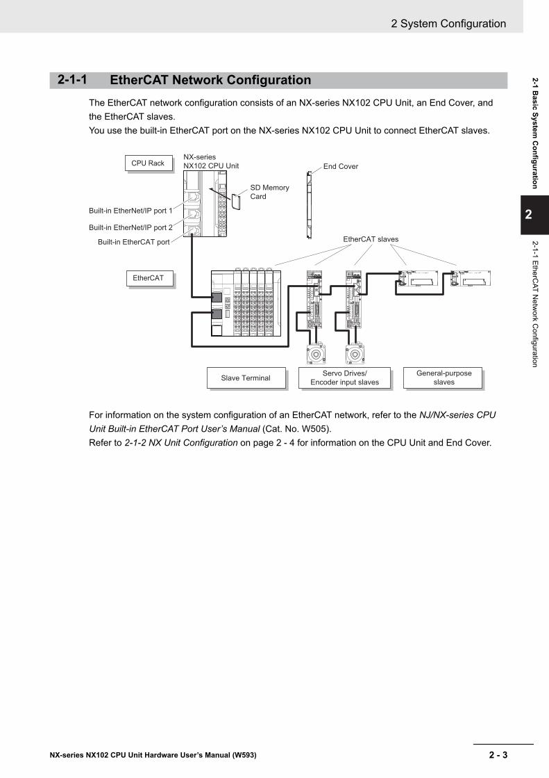
2-1-1 EtherCAT Network ConfigurationThe EtherCAT network configuration consists of an NX-series NX102 CPU Unit, an End Cover, andthe EtherCAT slaves.You use the built-in EtherCAT port on the NX-series NX102 CPU Unit to connect EtherCAT slaves.
ADR ADR
NX-series
NX102 CPU Unit
SD Memory
Card
Slave TerminalServo Drives/
Encoder input slaves
General-purpose
slaves
EtherCAT slaves
Built-in EtherNet/IP port 2
Built-in EtherNet/IP port 1
Built-in EtherCAT port
EtherCAT
CPU Rack End Cover
For information on the system configuration of an EtherCAT network, refer to the NJ/NX-series CPUUnit Built-in EtherCAT Port User’s Manual (Cat. No. W505).Refer to 2-1-2 NX Unit Configuration on page 2 - 4 for information on the CPU Unit and End Cover.
2 System Configuration
2 - 3NX-series NX102 CPU Unit Hardware User’s Manual (W593)
2-1 Basic System
Configuration
2
2-1-1 EtherCAT N
etwork C
onfiguration
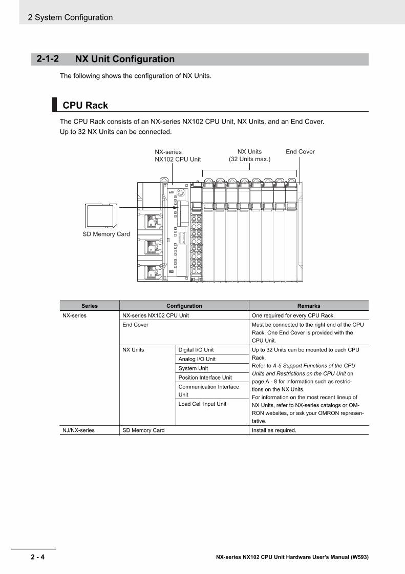
2-1-2 NX Unit ConfigurationThe following shows the configuration of NX Units.
CPU RackThe CPU Rack consists of an NX-series NX102 CPU Unit, NX Units, and an End Cover.Up to 32 NX Units can be connected.
NX-series
NX102 CPU Unit
SD Memory Card
End CoverNX Units
(32 Units max.)
Series Configuration RemarksNX-series NX-series NX102 CPU Unit One required for every CPU Rack.
End Cover Must be connected to the right end of the CPURack. One End Cover is provided with theCPU Unit.
NX Units Digital I/O Unit Up to 32 Units can be mounted to each CPURack.Refer to A-5 Support Functions of the CPUUnits and Restrictions on the CPU Unit onpage A - 8 for information such as restric-tions on the NX Units.For information on the most recent lineup ofNX Units, refer to NX-series catalogs or OM-RON websites, or ask your OMRON represen-tative.
Analog I/O UnitSystem UnitPosition Interface UnitCommunication InterfaceUnitLoad Cell Input Unit
NJ/NX-series SD Memory Card Install as required.
2 System Configuration
2 - 4 NX-series NX102 CPU Unit Hardware User’s Manual (W593)
Configuration Units
l NX-series NX102 CPU UnitThe Unit that serves as the center of control for a Machine Automation Controller. It executes tasks,refreshes I/O for other Units and slaves, etc. In the NX-series, this type of Units is called NX102CPU Unit.Refer to 3-1 CPU Units on page 3 - 2 for the models and specifications of individual NX-seriesNX102 CPU Unit.
l SD Memory CardWith the NX-series NX102 CPU Unit, various data can be saved, backed up, restored, and com-pared using the SD Memory Card.Refer to 3-2 SD Memory Cards on page 3 - 14 for the models and specifications of individual SDMemory Cards.
l NX UnitThe NX Units perform I/O processing with connected external devices. These Units are NX-seriesNX-££££££ Units.Up to 32 NX Units can be connected to the CPU Unit.Refer to A-5 Support Functions of the CPU Units and Restrictions on the CPU Unit on page A - 8for information such as restrictions on the NX Units.
l End CoverA cover to protect the NX Unit and CPU Unit. This is provided with the CPU Unit. The model num-ber is NX-END02.
l Recommended Communications Cables for EtherCAT and EtherNet/IPEtherCAT communications are performed in accordance with the 100BASE-TX standard. Refer tothe NJ/NX-series CPU Unit Built-in EtherCAT Port User’s Manual (Cat. No. W505) for recommend-ed cables.
EtherNet/IP communications are performed in accordance with the 100BASE-TX or 10BASE-Tstandard. Refer to the NJ/NX-series CPU Unit Built-in EtherNet/IP Port User’s Manual (Cat. No.W506) for recommended cables.
2 System Configuration
2 - 5NX-series NX102 CPU Unit Hardware User’s Manual (W593)
2-1 Basic System
Configuration
2
2-1-2 NX U
nit Configuration
2-2 Connecting to the Sysmac StudioConnect the NX-series NX102 CPU Unit and the Sysmac Studio through EtherNet/IP.Refer to 3-5-2 Connection on page 3 - 17 for information on how to make the connection between theNX-series NX102 CPU Unit and the Sysmac Studio.
2 System Configuration
2 - 6 NX-series NX102 CPU Unit Hardware User’s Manual (W593)
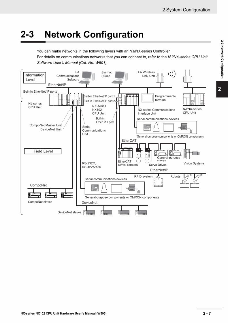
2-3 Network ConfigurationYou can make networks in the following layers with an NJ/NX-series Controller.For details on communications networks that you can connect to, refer to the NJ/NX-series CPU UnitSoftware User’s Manual (Cat. No. W501).
EtherCAT Slave Terminal
Vision Systems
Sysmac
Studio
EtherNet/IP
DeviceNet
EtherCAT
CompoNet
REMOTE TERMINAL
0 1 2 3 4 5 6 7 8 9 10 11 12 13 14 15
OUT
CRT1-OD16
MS NS WORD NODE ADR
REMOTE TERMINAL
0 1 2 3 4 5 6 7 8 9 10 11 12 13 14 15
OUT
CRT1-OD16
MS NS WORD NODE ADR
REMOTE TERMINAL
0 1 2 3 4 5 6 7 8 9 10 11 12 13 14 15
OUT
CRT1-OD16
MS NS WORD NODE ADR
EtherNet/IP
Built-in EtherNet/IP port 1
Built-in EtherNet/IP port 2
Built-in
EtherCAT port
Built-in EtherNet/IP ports
CompoNet Master Unit
CompoNet slaves
DeviceNet slaves
DeviceNet Unit
NJ-series
CPU Unit
Field Level
NX-series
NX102
CPU Unit
Serial
Communications
Unit
RS-232C,
RS-422A/485
RFID system Robots
Servo Drives
General-purpose slaves
Serial communications devices
NX-series Communications
Interface Unit
General-purpose components or OMRON components
Serial communications devices
General-purpose components or OMRON components
NJ/NX-series
CPU Unit
Programmable
terminal
FA Wireless
LAN Unit
FA
Communications
Software
Information
Level
2 System Configuration
2 - 7NX-series NX102 CPU Unit Hardware User’s Manual (W593)
2-3 Netw
ork Configuration
2
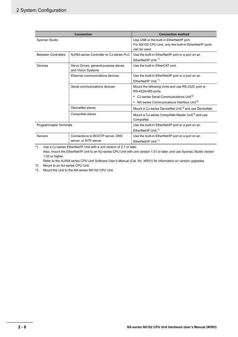
Connection Connection methodSysmac Studio Use USB or the built-in EtherNet/IP port.
For NX102 CPU Unit, only the built-in EtherNet/IP portscan be used.
Between Controllers NJ/NX-series Controller or CJ-series PLC Use the built-in EtherNet/IP port or a port on an
EtherNet/IP Unit.*1
Devices Servo Drives, general-purpose slavesand Vision Systems
Use the built-in EtherCAT port.
Ethernet communications devices Use the built-in EtherNet/IP port or a port on an
EtherNet/IP Unit.*1
Serial communications devices Mount the following Units and use RS-232C port orRS-422A/485 ports.
• CJ-series Serial Communications Unit*2
• NX-series Communications Interface Unit*3
DeviceNet slaves Mount a CJ-series DeviceNet Unit*2 and use DeviceNet.CompoNet slaves Mount a CJ-series CompoNet Master Unit*2 and use
CompoNet.Programmable Terminals Use the built-in EtherNet/IP port or a port on an
EtherNet/IP Unit.*1
Servers Connections to BOOTP server, DNSserver, or NTP server
Use the built-in EtherNet/IP port or a port on an
EtherNet/IP Unit.*1
*1. Use a CJ-series EtherNet/IP Unit with a unit version of 2.1 or later.Also, mount the EtherNet/IP Unit to an NJ-series CPU Unit with unit version 1.01 or later, and use Sysmac Studio version1.02 or higher.Refer to the NJ/NX-series CPU Unit Software User’s Manual (Cat. No. W501) for information on version upgrades.
*2. Mount to an NJ-series CPU Unit.*3. Mount the Unit to the NX-series NX102 CPU Unit.
2 System Configuration
2 - 8 NX-series NX102 CPU Unit Hardware User’s Manual (W593)
3Configuration Units
This section describes configuration devices in the NX-series Controller configuration.
3-1 CPU Units...................................................................................................... 3 - 23-1-1 Models and Specifications ............................................................................ 3 - 23-1-2 Part Names and Functions ........................................................................... 3 - 43-1-3 Operation Status Indicators .......................................................................... 3 - 63-1-4 Terminal Blocks........................................................................................... 3 - 103-1-5 Battery .........................................................................................................3 - 113-1-6 ID Information Indication............................................................................. 3 - 12
3-2 SD Memory Cards ...................................................................................... 3 - 143-2-1 Models and Specifications .......................................................................... 3 - 143-2-2 Purpose ...................................................................................................... 3 - 14
3-3 Power Supply-related Units ...................................................................... 3 - 153-4 NX Units ...................................................................................................... 3 - 163-5 Sysmac Studio ........................................................................................... 3 - 17
3-5-1 Model Numbers .......................................................................................... 3 - 173-5-2 Connection.................................................................................................. 3 - 17
3 - 1NX-series NX102 CPU Unit Hardware User’s Manual (W593)
3
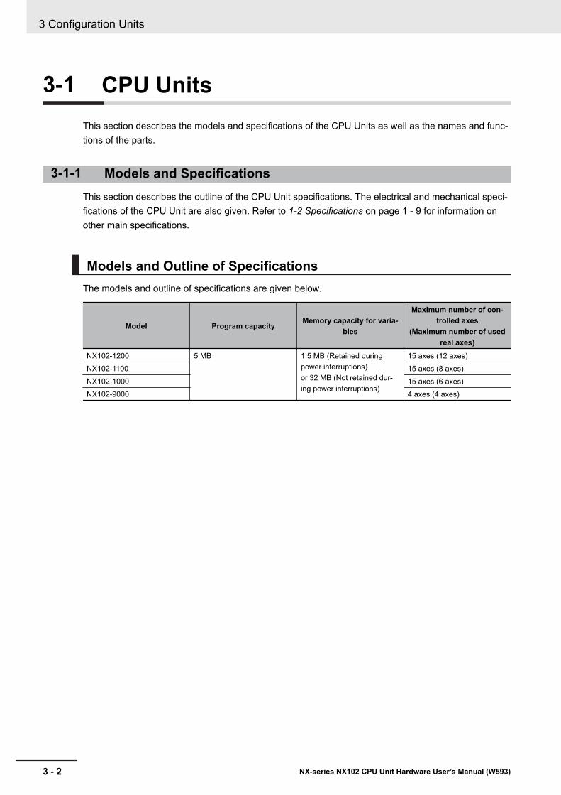
3-1 CPU UnitsThis section describes the models and specifications of the CPU Units as well as the names and func-tions of the parts.
3-1-1 Models and SpecificationsThis section describes the outline of the CPU Unit specifications. The electrical and mechanical speci-fications of the CPU Unit are also given. Refer to 1-2 Specifications on page 1 - 9 for information onother main specifications.
Models and Outline of SpecificationsThe models and outline of specifications are given below.
Model Program capacityMemory capacity for varia-
bles
Maximum number of con-trolled axes
(Maximum number of usedreal axes)
NX102-1200 5 MB 1.5 MB (Retained duringpower interruptions)or 32 MB (Not retained dur-ing power interruptions)
15 axes (12 axes)NX102-1100 15 axes (8 axes)NX102-1000 15 axes (6 axes)NX102-9000 4 axes (4 axes)
3 Configuration Units
3 - 2 NX-series NX102 CPU Unit Hardware User’s Manual (W593)
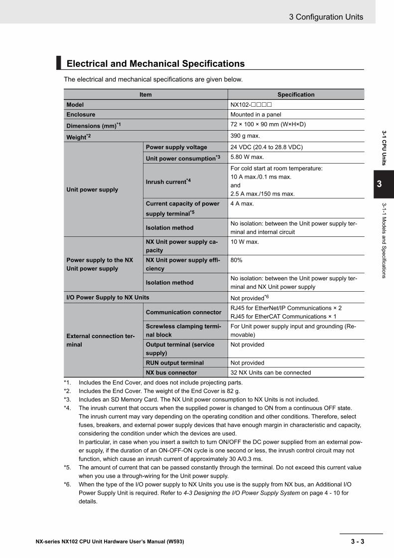
Electrical and Mechanical SpecificationsThe electrical and mechanical specifications are given below.
Item SpecificationModel NX102-££££Enclosure Mounted in a panel
Dimensions (mm)*1 72 × 100 × 90 mm (W×H×D)
Weight*2 390 g max.
Unit power supply
Power supply voltage 24 VDC (20.4 to 28.8 VDC)
Unit power consumption*3 5.80 W max.
Inrush current*4
For cold start at room temperature:10 A max./0.1 ms max.and2.5 A max./150 ms max.
Current capacity of powersupply terminal*5
4 A max.
Isolation method No isolation: between the Unit power supply ter-minal and internal circuit
Power supply to the NXUnit power supply
NX Unit power supply ca-pacity
10 W max.
NX Unit power supply effi-ciency
80%
Isolation method No isolation: between the Unit power supply ter-minal and NX Unit power supply
I/O Power Supply to NX Units Not provided*6
External connection ter-minal
Communication connector RJ45 for EtherNet/IP Communications × 2RJ45 for EtherCAT Communications × 1
Screwless clamping termi-nal block
For Unit power supply input and grounding (Re-movable)
Output terminal (servicesupply)
Not provided
RUN output terminal Not providedNX bus connector 32 NX Units can be connected
*1. Includes the End Cover, and does not include projecting parts.*2. Includes the End Cover. The weight of the End Cover is 82 g.*3. Includes an SD Memory Card. The NX Unit power consumption to NX Units is not included.*4. The inrush current that occurs when the supplied power is changed to ON from a continuous OFF state.
The inrush current may vary depending on the operating condition and other conditions. Therefore, selectfuses, breakers, and external power supply devices that have enough margin in characteristic and capacity,considering the condition under which the devices are used.In particular, in case when you insert a switch to turn ON/OFF the DC power supplied from an external pow-er supply, if the duration of an ON-OFF-ON cycle is one second or less, the inrush control circuit may notfunction, which cause an inrush current of approximately 30 A/0.3 ms.
*5. The amount of current that can be passed constantly through the terminal. Do not exceed this current valuewhen you use a through-wiring for the Unit power supply.
*6. When the type of the I/O power supply to NX Units you use is the supply from NX bus, an Additional I/OPower Supply Unit is required. Refer to 4-3 Designing the I/O Power Supply System on page 4 - 10 fordetails.
3 Configuration Units
3 - 3NX-series NX102 CPU Unit Hardware User’s Manual (W593)
3-1 CPU
Units
3
3-1-1 Models and Specifications
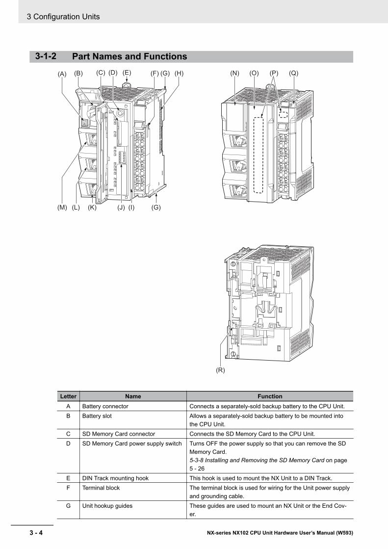
3-1-2 Part Names and Functions
(A) (B) (C) (D) (G) (H)(E) (F) (N)
(I)
(O) (Q)(P)
(J)(M) (K)(L) (G)
(R)
Letter Name FunctionA Battery connector Connects a separately-sold backup battery to the CPU Unit.B Battery slot Allows a separately-sold backup battery to be mounted into
the CPU Unit.C SD Memory Card connector Connects the SD Memory Card to the CPU Unit.D SD Memory Card power supply switch Turns OFF the power supply so that you can remove the SD
Memory Card.5-3-8 Installing and Removing the SD Memory Card on page5 - 26
E DIN Track mounting hook This hook is used to mount the NX Unit to a DIN Track.F Terminal block The terminal block is used for wiring for the Unit power supply
and grounding cable.G Unit hookup guides These guides are used to mount an NX Unit or the End Cov-
er.
3 Configuration Units
3 - 4 NX-series NX102 CPU Unit Hardware User’s Manual (W593)
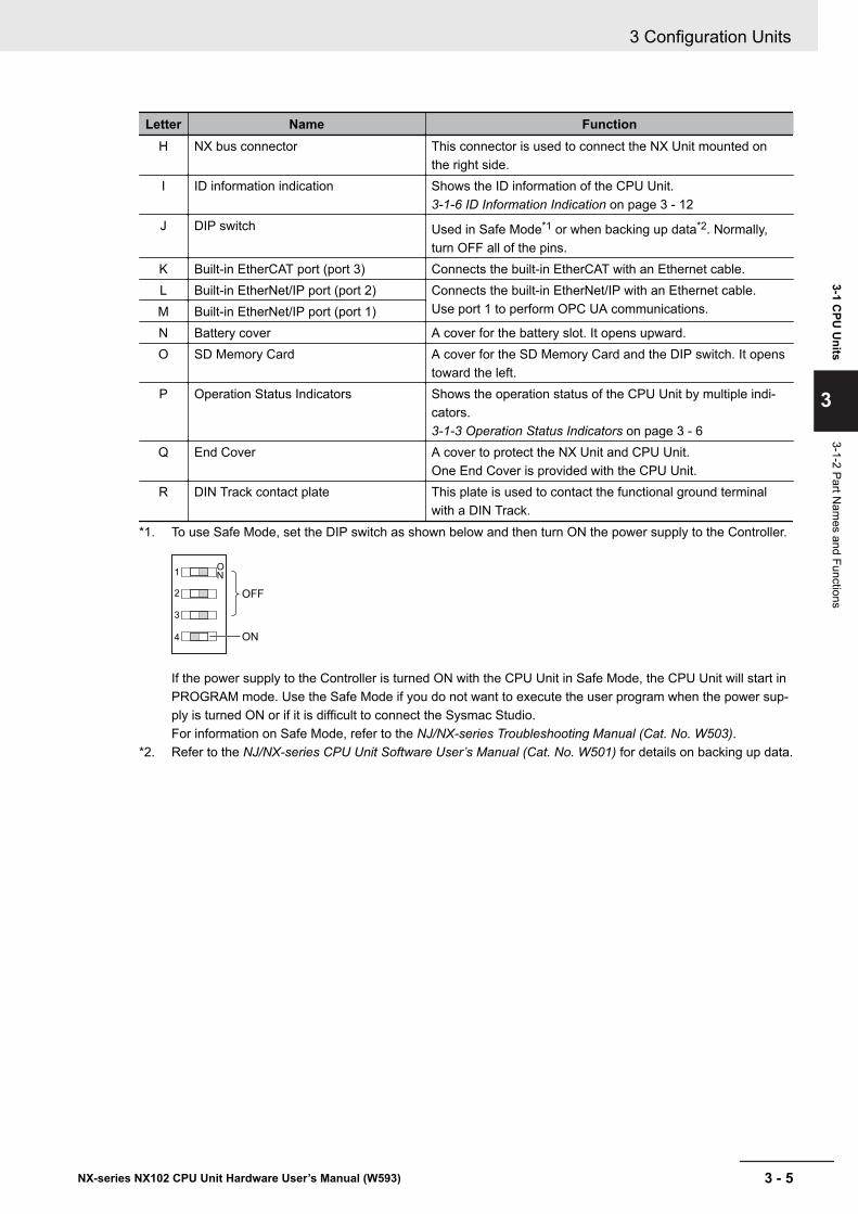
Letter Name FunctionH NX bus connector This connector is used to connect the NX Unit mounted on
the right side.I ID information indication Shows the ID information of the CPU Unit.
3-1-6 ID Information Indication on page 3 - 12J DIP switch Used in Safe Mode*1 or when backing up data*2. Normally,
turn OFF all of the pins.K Built-in EtherCAT port (port 3) Connects the built-in EtherCAT with an Ethernet cable.L Built-in EtherNet/IP port (port 2) Connects the built-in EtherNet/IP with an Ethernet cable.
Use port 1 to perform OPC UA communications.M Built-in EtherNet/IP port (port 1)N Battery cover A cover for the battery slot. It opens upward.O SD Memory Card A cover for the SD Memory Card and the DIP switch. It opens
toward the left.P Operation Status Indicators Shows the operation status of the CPU Unit by multiple indi-
cators.3-1-3 Operation Status Indicators on page 3 - 6
Q End Cover A cover to protect the NX Unit and CPU Unit.One End Cover is provided with the CPU Unit.
R DIN Track contact plate This plate is used to contact the functional ground terminalwith a DIN Track.
*1. To use Safe Mode, set the DIP switch as shown below and then turn ON the power supply to the Controller.
OFF
ON
ON1
2
3
4
If the power supply to the Controller is turned ON with the CPU Unit in Safe Mode, the CPU Unit will start inPROGRAM mode. Use the Safe Mode if you do not want to execute the user program when the power sup-ply is turned ON or if it is difficult to connect the Sysmac Studio.For information on Safe Mode, refer to the NJ/NX-series Troubleshooting Manual (Cat. No. W503).
*2. Refer to the NJ/NX-series CPU Unit Software User’s Manual (Cat. No. W501) for details on backing up data.
3 Configuration Units
3 - 5NX-series NX102 CPU Unit Hardware User’s Manual (W593)
3-1 CPU
Units
3
3-1-2 Part Nam
es and Functions
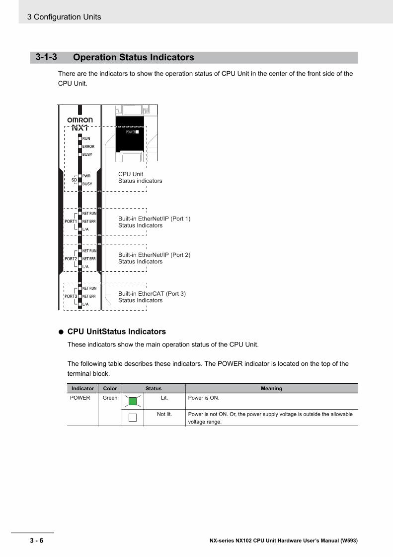
3-1-3 Operation Status IndicatorsThere are the indicators to show the operation status of CPU Unit in the center of the front side of theCPU Unit.
Built-in EtherNet/IP (Port 1)
Status Indicators
Built-in EtherNet/IP (Port 2)
Status Indicators
Built-in EtherCAT (Port 3)
Status Indicators
CPU Unit
Status indicators
l CPU UnitStatus IndicatorsThese indicators show the main operation status of the CPU Unit.
The following table describes these indicators. The POWER indicator is located on the top of theterminal block.
Indicator Color Status MeaningPOWER Green Lit. Power is ON.
Not lit. Power is not ON. Or, the power supply voltage is outside the allowablevoltage range.
3 Configuration Units
3 - 6 NX-series NX102 CPU Unit Hardware User’s Manual (W593)

Indicator Color Status MeaningRUN Green Lit. The CPU Unit is in normal operation in RUN mode. (The user program
is in execution.)Flashing
at 2-s intervals,then flashing at0.5-s intervals.
The CPU Unit is starting (entering RUN mode or PROGRAM mode atstartup).
Flashingat 2-s intervalscontinues for30 seconds or
longer.
System initialization error occurs.
Not lit. Operation is stopped in PROGRAM mode, when a CPU Unit reset is inprogress, or when any of the following errors occurs.• Controller error in the major fault level• CPU error (WDT error)
ERROR Red Lit. Self-diagnosis found one of the following errors.• Controller error in the major fault level• CPU error
Flashingat 1-s intervals.
Self-diagnosis found one of the following errors.• Controller error in the partial fault level (an error in which all control
of a Function Module is disabled)• Controller error in the minor fault level (an error in which partial con-
trol of a Function Module is disabled)CPU Unit operation will continue for either of these errors.Operation will stop for the Function Module in which a Controller errorin the partial fault level occurred.Operation will continue for the Function Module in which a Controllererror in the minor fault level occurred.
Not lit. The CPU Unit is in normal operation, a CPU reset is in progress, ormonitored information occurred (CPU Unit operation will continue.).
BUSY Yellow Flashing Built-in non-volatile memory access in progress.
Not lit. Other than the above.
SD PWR Green Lit. Power is being supplied to the SD Memory Card and the SD MemoryCard can be used.
Flashing A backup, restore or verification operation is in progress.*1
Not lit. The power supply for the SD Memory Card is stopped, an SD MemoryCard is not mounted, or the file format of the mounted SD MemoryCard is not supported.
SD BUSY Yellow Flashing SD Memory Card access in progress.
Not lit. SD Memory Card access not in progress.
*1. Refer to the NJ/NX-series CPU Unit Software User’s Manual (Cat. No. W501) for details on backing up data.
3 Configuration Units
3 - 7NX-series NX102 CPU Unit Hardware User’s Manual (W593)
3-1 CPU
Units
3
3-1-3 Operation Status Indicators
Precautions for Safe Use
• Never turn OFF the power supply to the Controller when the BUSY indicator is flashing. Whilethe BUSY indicator is lit, the user program and settings in the CPU Unit are being backed upin the built-in non-volatile memory. The data will not be backed up if the power supply isturned OFF. Also, a major fault level Controller error will occur the next time you start opera-tion, and operation will stop.
• Do not turn OFF the power supply or remove the SD Memory Card while SD Memory Cardaccess is in progress (i.e., while the SD BUSY indicator flashes). Data may become corrupt-ed, and the Controller will not operate correctly if it uses corrupted data. To remove the SDMemory Card from the CPU Unit while the power supply is ON, press the SD Memory Cardpower supply switch and wait for the SD BUSY indicator and SD PWR indicator to turn OFFbefore you remove the SD Memory Card.
You can check the operation status of the CPU Unit with the CPU Unit status indicators (POWER,RUN, and ERROR indicators).Refer to the NJ/NX-series Troubleshooting Manual (Cat. No. W503) for the procedures to check theoperation status of the CPU Unit.
3 Configuration Units
3 - 8 NX-series NX102 CPU Unit Hardware User’s Manual (W593)
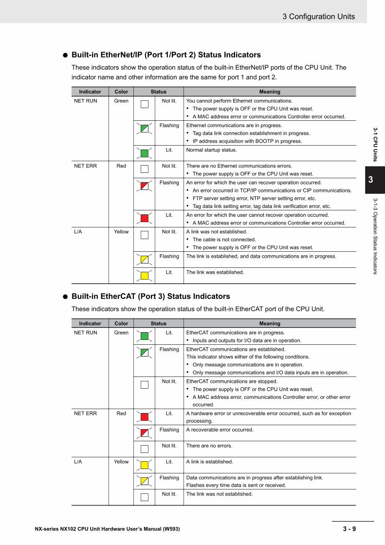
l Built-in EtherNet/IP (Port 1/Port 2) Status IndicatorsThese indicators show the operation status of the built-in EtherNet/IP ports of the CPU Unit. Theindicator name and other information are the same for port 1 and port 2.
Indicator Color Status MeaningNET RUN Green Not lit. You cannot perform Ethernet communications.
• The power supply is OFF or the CPU Unit was reset.• A MAC address error or communications Controller error occurred.
Flashing Ethernet communications are in progress.• Tag data link connection establishment in progress.• IP address acquisition with BOOTP in progress.
Lit. Normal startup status.
NET ERR Red Not lit. There are no Ethernet communications errors.• The power supply is OFF or the CPU Unit was reset.
Flashing An error for which the user can recover operation occurred.• An error occurred in TCP/IP communications or CIP communications.• FTP server setting error, NTP server setting error, etc.• Tag data link setting error, tag data link verification error, etc.
Lit. An error for which the user cannot recover operation occurred.• A MAC address error or communications Controller error occurred.
L/A Yellow Not lit. A link was not established.• The cable is not connected.• The power supply is OFF or the CPU Unit was reset.
Flashing The link is established, and data communications are in progress.
Lit. The link was established.
l Built-in EtherCAT (Port 3) Status IndicatorsThese indicators show the operation status of the built-in EtherCAT port of the CPU Unit.
Indicator Color Status MeaningNET RUN Green Lit. EtherCAT communications are in progress.
• Inputs and outputs for I/O data are in operation.Flashing EtherCAT communications are established.
This indicator shows either of the following conditions.• Only message communications are in operation.• Only message communications and I/O data inputs are in operation.
Not lit. EtherCAT communications are stopped.• The power supply is OFF or the CPU Unit was reset.• A MAC address error, communications Controller error, or other error
occurred.NET ERR Red Lit. A hardware error or unrecoverable error occurred, such as for exception
processing.Flashing A recoverable error occurred.
Not lit. There are no errors.
L/A Yellow Lit. A link is established.
Flashing Data communications are in progress after establishing link.Flashes every time data is sent or received.
Not lit. The link was not established.
3 Configuration Units
3 - 9NX-series NX102 CPU Unit Hardware User’s Manual (W593)
3-1 CPU
Units
3
3-1-3 Operation Status Indicators
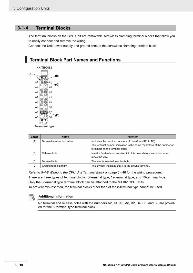
3-1-4 Terminal BlocksThe terminal blocks on the CPU Unit are removable screwless clamping terminal blocks that allow youto easily connect and remove the wiring.Connect the Unit power supply and ground lines to the screwless clamping terminal block.
Terminal Block Part Names and Functions
(A)
A1
A2
A3
A4
A5
A6
A7
A8
B1
B2
B3
B4
B5
B6
B7
B8
(B)
(C)
(D)
NX-TBC082
8-terminal type
Letter Name Function(A) Terminal number indication Indicates the terminal numbers (A1 to A8 and B1 to B8).
The terminal number indication is the same regardless of the number ofterminals on the terminal block.
(B) Release hole Insert a flat-blade screwdriver into this hole when you connect or re-move the wire.
(C) Terminal hole The wire is inserted into this hole.(D) Ground terminal mark This symbol indicates that it is the ground terminal.
Refer to 5-4-8 Wiring to the CPU Unit Terminal Block on page 5 - 46 for the wiring procedure.There are three types of terminal blocks: 8-terminal type, 12-terminal type, and 16-terminal type.Only the 8-terminal type terminal block can be attached to the NX102 CPU Units.To prevent mis-insertion, the terminal blocks other than of the 8-terminal type cannot be used.
Additional Information
No terminal and release holes with the numbers A2, A4, A6, A8, B2, B4, B6, and B8 are provid-ed for the 8-terminal type terminal block.
3 Configuration Units
3 - 10 NX-series NX102 CPU Unit Hardware User’s Manual (W593)
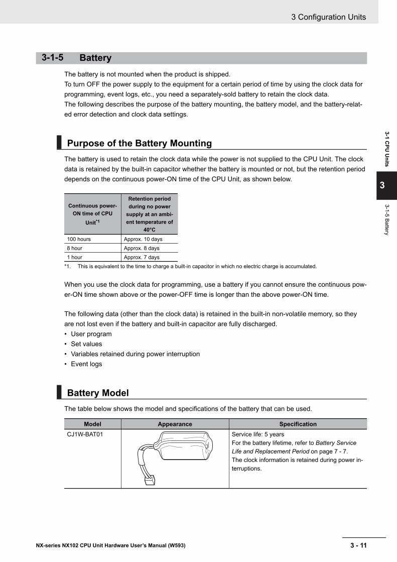
3-1-5 BatteryThe battery is not mounted when the product is shipped.To turn OFF the power supply to the equipment for a certain period of time by using the clock data forprogramming, event logs, etc., you need a separately-sold battery to retain the clock data.The following describes the purpose of the battery mounting, the battery model, and the battery-relat-ed error detection and clock data settings.
Purpose of the Battery MountingThe battery is used to retain the clock data while the power is not supplied to the CPU Unit. The clockdata is retained by the built-in capacitor whether the battery is mounted or not, but the retention perioddepends on the continuous power-ON time of the CPU Unit, as shown below.
Continuous power-ON time of CPU
Unit*1
Retention periodduring no power
supply at an ambi-ent temperature of
40°C100 hours Approx. 10 days8 hour Approx. 8 days1 hour Approx. 7 days
*1. This is equivalent to the time to charge a built-in capacitor in which no electric charge is accumulated.
When you use the clock data for programming, use a battery if you cannot ensure the continuous pow-er-ON time shown above or the power-OFF time is longer than the above power-ON time.
The following data (other than the clock data) is retained in the built-in non-volatile memory, so theyare not lost even if the battery and built-in capacitor are fully discharged.• User program• Set values• Variables retained during power interruption• Event logs
Battery ModelThe table below shows the model and specifications of the battery that can be used.
Model Appearance SpecificationCJ1W-BAT01 Service life: 5 years
For the battery lifetime, refer to Battery ServiceLife and Replacement Period on page 7 - 7.The clock information is retained during power in-terruptions.
3 Configuration Units
3 - 11NX-series NX102 CPU Unit Hardware User’s Manual (W593)
3-1 CPU
Units
3
3-1-5 Battery
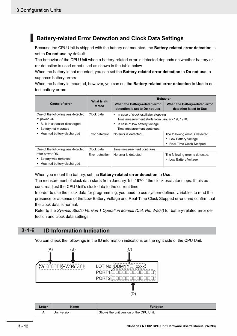
Battery-related Error Detection and Clock Data SettingsBecause the CPU Unit is shipped with the battery not mounted, the Battery-related error detection isset to Do not use by default.The behavior of the CPU Unit when a battery-related error is detected depends on whether battery er-ror detection is used or not used as shown in the table below.When the battery is not mounted, you can set the Battery-related error detection to Do not use tosuppress battery errors.When the battery is mounted, however, you can set the Battery-related error detection to Use to de-tect battery errors.
Cause of errorWhat is af-
fected
BehaviorWhen the Battery-related errordetection is set to Do not use
When the Battery-related errordetection is set to Use
One of the following was detectedat power ON.• Built-in capacitor discharged• Battery not mounted• Mounted battery discharged
Clock data • In case of clock oscillator stoppingTime measurement starts from January 1st, 1970.
• In case of low battery voltageTime measurement continues.
Error detection No error is detected. The following error is detected.• Low Battery Voltage• Real-Time Clock Stopped
One of the following was detectedafter power ON.• Battery was removed• Mounted battery discharged
Clock data Time measurement continues.Error detection No error is detected. The following error is detected.
• Low Battery Voltage
When you mount the battery, set the Battery-related error detection to Use.The measurement of clock data starts from January 1st, 1970 if the clock oscillator stops. If this oc-curs, readjust the CPU Unit’s clock data to the current time.In order to use the clock data for programming, you need to use system-defined variables to read thepresence or absence of the Low Battery Voltage and Real-Time Clock Stopped errors and confirm thatthe clock data is normal.Refer to the Sysmac Studio Version 1 Operation Manual (Cat. No. W504) for battery-related error de-tection and clock data settings.
3-1-6 ID Information IndicationYou can check the followings in the ID information indications on the right side of the CPU Unit.
(A)
(D)
LOT No. DDMYY£ xxxx
PORT1 ££££££££££££
PORT2 ££££££££££££
Ver.£.££ HW Rev.£
(B) (C)
Letter Name FunctionA Unit version Shows the unit version of the CPU Unit.
3 Configuration Units
3 - 12 NX-series NX102 CPU Unit Hardware User’s Manual (W593)
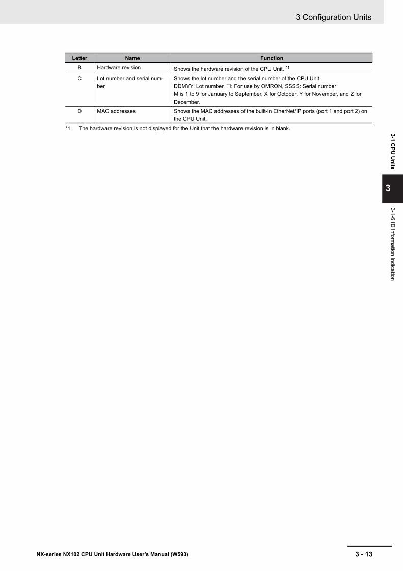
Letter Name FunctionB Hardware revision Shows the hardware revision of the CPU Unit. *1
C Lot number and serial num-ber
Shows the lot number and the serial number of the CPU Unit.DDMYY: Lot number, £: For use by OMRON, SSSS: Serial numberM is 1 to 9 for January to September, X for October, Y for November, and Z forDecember.
D MAC addresses Shows the MAC addresses of the built-in EtherNet/IP ports (port 1 and port 2) onthe CPU Unit.
*1. The hardware revision is not displayed for the Unit that the hardware revision is in blank.
3 Configuration Units
3 - 13NX-series NX102 CPU Unit Hardware User’s Manual (W593)
3-1 CPU
Units
3
3-1-6 ID Inform
ation Indication
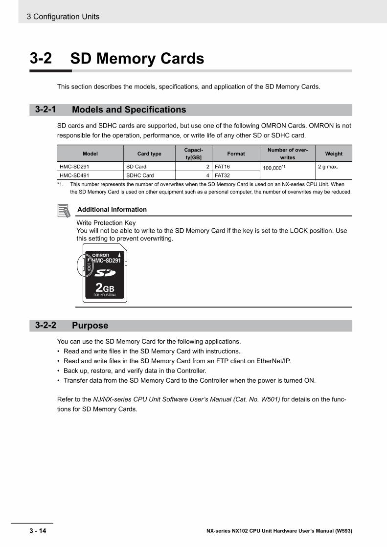
3-2 SD Memory CardsThis section describes the models, specifications, and application of the SD Memory Cards.
3-2-1 Models and SpecificationsSD cards and SDHC cards are supported, but use one of the following OMRON Cards. OMRON is notresponsible for the operation, performance, or write life of any other SD or SDHC card.
Model Card typeCapaci-ty[GB]
FormatNumber of over-
writesWeight
HMC-SD291 SD Card 2 FAT16 100,000*1 2 g max.HMC-SD491 SDHC Card 4 FAT32
*1. This number represents the number of overwrites when the SD Memory Card is used on an NX-series CPU Unit. Whenthe SD Memory Card is used on other equipment such as a personal computer, the number of overwrites may be reduced.
Additional Information
Write Protection KeyYou will not be able to write to the SD Memory Card if the key is set to the LOCK position. Usethis setting to prevent overwriting.
3-2-2 PurposeYou can use the SD Memory Card for the following applications.• Read and write files in the SD Memory Card with instructions.• Read and write files in the SD Memory Card from an FTP client on EtherNet/IP.• Back up, restore, and verify data in the Controller.• Transfer data from the SD Memory Card to the Controller when the power is turned ON.
Refer to the NJ/NX-series CPU Unit Software User’s Manual (Cat. No. W501) for details on the func-tions for SD Memory Cards.
3 Configuration Units
3 - 14 NX-series NX102 CPU Unit Hardware User’s Manual (W593)
3-3 Power Supply-related UnitsThe following NX Units are the NX-series power supply-related Units. When configuring NX Units, youcan use these Units as necessary to supply power to the NX Units. These NX Units are collectivelycalled as the System Units.
• Additional NX Unit Power Supply Unit• Additional I/O Power Supply Unit• I/O Power Supply Connection Unit
Refer to 4-1-2 NX-series Power Supply-related Units on page 4 - 4 for details on the functions ofNX-series power supply-related Units.
3 Configuration Units
3 - 15NX-series NX102 CPU Unit Hardware User’s Manual (W593)
3-3 Power Supply-related U
nits
3
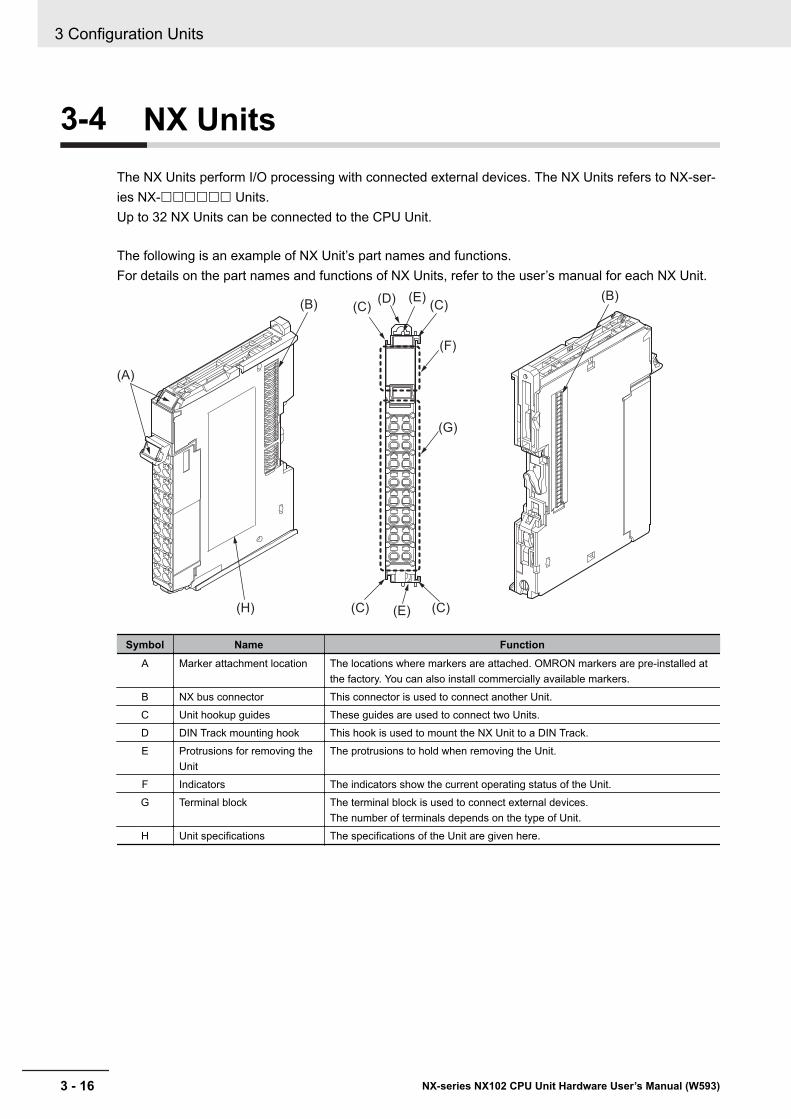
3-4 NX UnitsThe NX Units perform I/O processing with connected external devices. The NX Units refers to NX-ser-ies NX-££££££ Units.Up to 32 NX Units can be connected to the CPU Unit.
The following is an example of NX Unit’s part names and functions.For details on the part names and functions of NX Units, refer to the user’s manual for each NX Unit.
(A)
(H)
(B)(B)
(C)
(G)
(F)
(C)
(C)
(C)
(D) (E)
(E)
Symbol Name FunctionA Marker attachment location The locations where markers are attached. OMRON markers are pre-installed at
the factory. You can also install commercially available markers.B NX bus connector This connector is used to connect another Unit.C Unit hookup guides These guides are used to connect two Units.D DIN Track mounting hook This hook is used to mount the NX Unit to a DIN Track.E Protrusions for removing the
UnitThe protrusions to hold when removing the Unit.
F Indicators The indicators show the current operating status of the Unit.G Terminal block The terminal block is used to connect external devices.
The number of terminals depends on the type of Unit.H Unit specifications The specifications of the Unit are given here.
3 Configuration Units
3 - 16 NX-series NX102 CPU Unit Hardware User’s Manual (W593)
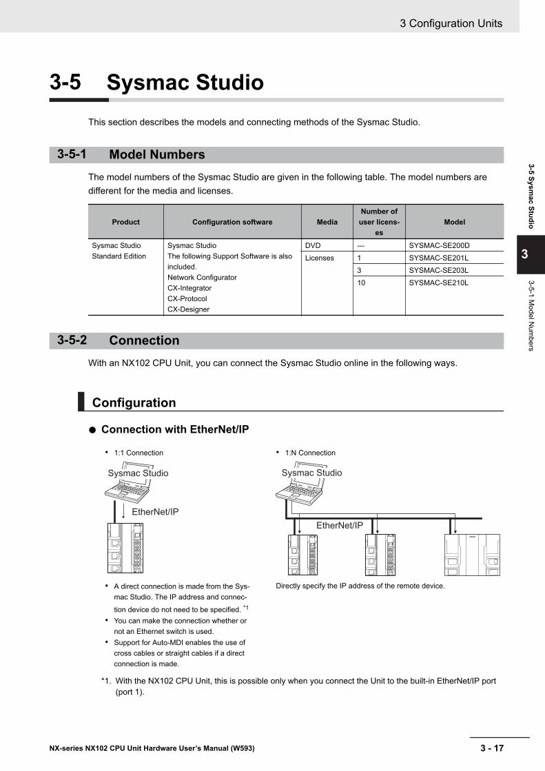
3-5 Sysmac StudioThis section describes the models and connecting methods of the Sysmac Studio.
3-5-1 Model NumbersThe model numbers of the Sysmac Studio are given in the following table. The model numbers aredifferent for the media and licenses.
Product Configuration software MediaNumber of
user licens-es
Model
Sysmac StudioStandard Edition
Sysmac StudioThe following Support Software is alsoincluded.Network ConfiguratorCX-IntegratorCX-ProtocolCX-Designer
DVD --- SYSMAC-SE200DLicenses 1 SYSMAC-SE201L
3 SYSMAC-SE203L10 SYSMAC-SE210L
3-5-2 ConnectionWith an NX102 CPU Unit, you can connect the Sysmac Studio online in the following ways.
Configuration
l Connection with EtherNet/IP
• 1:1 Connection • 1:N Connection
EtherNet/IP
Sysmac Studio
EtherNet/IP
Sysmac Studio
• A direct connection is made from the Sys-mac Studio. The IP address and connec-
tion device do not need to be specified. *1
• You can make the connection whether ornot an Ethernet switch is used.
• Support for Auto-MDI enables the use ofcross cables or straight cables if a directconnection is made.
Directly specify the IP address of the remote device.
*1. With the NX102 CPU Unit, this is possible only when you connect the Unit to the built-in EtherNet/IP port(port 1).
3 Configuration Units
3 - 17NX-series NX102 CPU Unit Hardware User’s Manual (W593)
3-5 Sysmac Studio
3
3-5-1 Model N
umbers
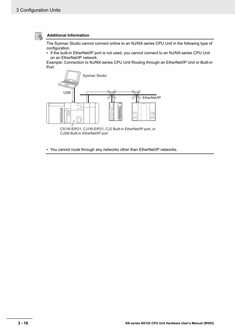
Additional Information
The Sysmac Studio cannot connect online to an NJ/NX-series CPU Unit in the following type ofconfiguration.• If the built-in EtherNet/IP port is not used, you cannot connect to an NJ/NX-series CPU Unit
on an EtherNet/IP network.Example: Connection to NJ/NX-series CPU Unit Routing through an EtherNet/IP Unit or Built-inPort
Sysmac Studio
USB
EtherNet/IP
CS1W-EIP21, CJ1W-EIP21, CJ2 Built-in EtherNet/IP port, or
CJ2M Built-in EtherNet/IP port
• You cannot route through any networks other than EtherNet/IP networks.
3 Configuration Units
3 - 18 NX-series NX102 CPU Unit Hardware User’s Manual (W593)
4Designing the Power Supply Sys-tem
This section describes how to design the power supply system for the NX-seriesNX102 CPU Unit.
4-1 Power Supply System and Design Concepts............................................ 4 - 24-1-1 Power Supply System and Types of Power Supplies ................................... 4 - 24-1-2 NX-series Power Supply-related Units ......................................................... 4 - 44-1-3 Design Concepts for Power Supply to the CPU Rack .................................. 4 - 6
4-2 Designing the NX Unit Power Supply System........................................... 4 - 74-2-1 Procedure for Designing the NX Unit Power Supply System ....................... 4 - 74-2-2 Calculation Example for the NX Unit Power Supply ..................................... 4 - 8
4-3 Designing the I/O Power Supply System ................................................. 4 - 104-3-1 I/O Power Supply Method........................................................................... 4 - 104-3-2 Designing the I/O Power Supply from the NX Bus ......................................4 - 114-3-3 Designing the I/O Power Supply from External Sources ............................ 4 - 164-3-4 Restrictions on Inrush Current for ON/OFF Operation ............................... 4 - 17
4-4 Selecting External Power Supplies and Protective Devices.................. 4 - 184-4-1 Selecting the Unit Power Supply ................................................................ 4 - 184-4-2 Selecting the I/O Power Supplies ............................................................... 4 - 204-4-3 Selecting Protective Devices ...................................................................... 4 - 21
4 - 1NX-series NX102 CPU Unit Hardware User’s Manual (W593)
4
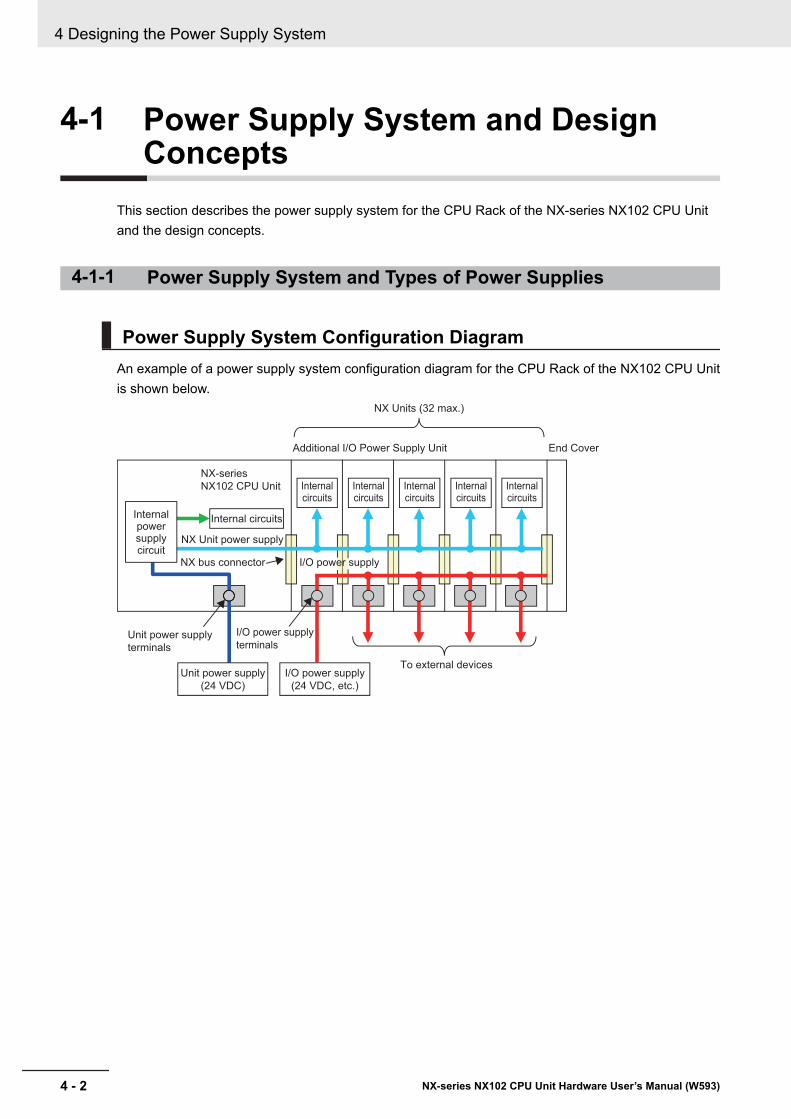
4-1 Power Supply System and DesignConcepts
This section describes the power supply system for the CPU Rack of the NX-series NX102 CPU Unitand the design concepts.
4-1-1 Power Supply System and Types of Power Supplies
Power Supply System Configuration DiagramAn example of a power supply system configuration diagram for the CPU Rack of the NX102 CPU Unitis shown below.
Internal circuits
Internal circuits
Internal circuits
Internal circuits
Internal circuits
NX Units (32 max.)
Unit power supply
terminals
To external devices
End Cover
I/O power supply
terminals
NX bus connector
NX Unit power supply
NX-series
NX102 CPU Unit
Additional I/O Power Supply Unit
I/O power supply
(24 VDC, etc.)
Internal circuitsInternal power supply circuit
Unit power supply
(24 VDC)
I/O power supply
4 Designing the Power Supply System
4 - 2 NX-series NX102 CPU Unit Hardware User’s Manual (W593)
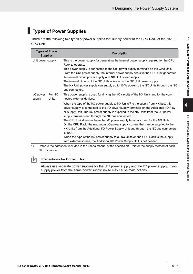
Types of Power SuppliesThere are the following two types of power supplies that supply power to the CPU Rack of the NX102CPU Unit.
Types of PowerSupplies Description
Unit power supply This is the power supply for generating the internal power supply required for the CPURack to operate.This power supply is connected to the Unit power supply terminals on the CPU Unit.From the Unit power supply, the internal power supply circuit in the CPU Unit generatesthe internal circuit power supply and NX Unit power supply.The internal circuits of the NX Units operate on the NX Unit power supply.The NX Unit power supply can supply up to 10 W power to the NX Units through the NXbus connectors.
I/O powersupply
For NXUnits
This power supply is used for driving the I/O circuits of the NX Units and for the con-nected external devices.When the type of the I/O power supply to NX Units*1 is the supply from NX bus, thispower supply is connected to the I/O power supply terminals on the Additional I/O Pow-er Supply Unit. The I/O power supply is supplied to the NX Units from the I/O powersupply terminals and through the NX bus connectors.The CPU Unit does not have the I/O power supply terminals used for the NX Units.On the CPU Rack, the maximum I/O power supply current that can be supplied to theNX Units from the Additional I/O Power Supply Unit and through the NX bus connectorsis 10 A.When the type of the I/O power supply to all NX Units on the CPU Rack is the supplyfrom external source, the Additional I/O Power Supply Unit is not needed.
*1. Refer to the datasheet included in the user’s manual of the specific NX Unit for the supply method of eachNX Unit model.
Precautions for Correct Use
Always use separate power supplies for the Unit power supply and the I/O power supply. If yousupply power from the same power supply, noise may cause malfunctions.
4 Designing the Power Supply System
4 - 3NX-series NX102 CPU Unit Hardware User’s Manual (W593)
4-1 Power Supply System
and Design C
oncepts
4
4-1-1 Power Supply System
and Types of Power Supplies
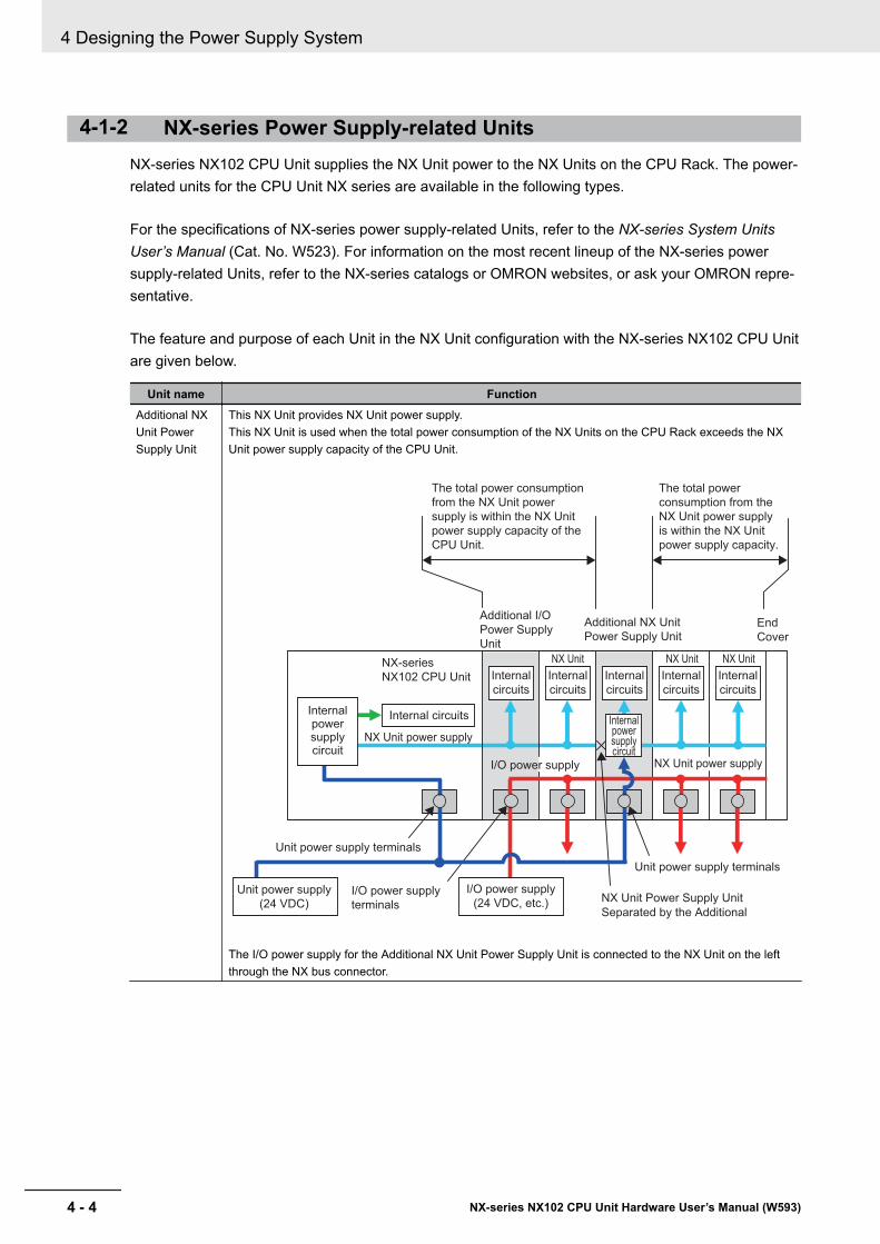
4-1-2 NX-series Power Supply-related UnitsNX-series NX102 CPU Unit supplies the NX Unit power to the NX Units on the CPU Rack. The power-related units for the CPU Unit NX series are available in the following types.
For the specifications of NX-series power supply-related Units, refer to the NX-series System UnitsUser’s Manual (Cat. No. W523). For information on the most recent lineup of the NX-series powersupply-related Units, refer to the NX-series catalogs or OMRON websites, or ask your OMRON repre-sentative.
The feature and purpose of each Unit in the NX Unit configuration with the NX-series NX102 CPU Unitare given below.
Unit name FunctionAdditional NXUnit PowerSupply Unit
This NX Unit provides NX Unit power supply.This NX Unit is used when the total power consumption of the NX Units on the CPU Rack exceeds the NXUnit power supply capacity of the CPU Unit.
Unit power supply terminals
NX Unit Power Supply Unit
Separated by the Additional
End
Cover
NX-series
NX102 CPU Unit Internal
circuits
Internal
circuits
Internal power supply circuit
Internal circuits
NX Unit power supply
NX Unit NX Unit NX Unit
I/O power supply
terminals
Unit power supply terminals
I/O power supply
Additional I/O
Power Supply
Unit
The total power consumption
from the NX Unit power
supply is within the NX Unit
power supply capacity of the
CPU Unit.
The total power
consumption from the
NX Unit power supply
is within the NX Unit
power supply capacity.
Additional NX Unit
Power Supply Unit
Unit power supply
(24 VDC)
NX Unit power supply
Internal power supplycircuit
I/O power supply
(24 VDC, etc.)
Internal
circuits
Internal
circuits
Internal
circuits
The I/O power supply for the Additional NX Unit Power Supply Unit is connected to the NX Unit on the leftthrough the NX bus connector.
4 Designing the Power Supply System
4 - 4 NX-series NX102 CPU Unit Hardware User’s Manual (W593)
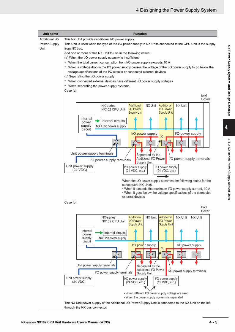
Unit name FunctionAdditional I/OPower SupplyUnit
This NX Unit provides additional I/O power supply.This Unit is used when the type of the I/O power supply to NX Units connected to the CPU Unit is the supplyfrom NX bus.Add one or more of this NX Unit to use in the following cases.(a) When the I/O power supply capacity is insufficient• When the total current consumption from I/O power supply exceeds 10 A• When a voltage drop in the I/O power supply causes the voltage of the I/O power supply to go below the
voltage specifications of the I/O circuits or connected external devices(b) Separating the I/O power supply• When connected external devices have different I/O power supply voltages• When separating the power supply systemsCase (a)
When the I/O power supply becomes the following states for the subsequent NX Units.• When it exceeds the maximum I/O power supply current, 10 A• When it goes below the voltage specifications of the connected external devices
NX Unit NX Unit
End Cover
Separated by the Additional I/O Power Supply Unit
I/O power supply terminals
NX-series
NX102 CPU Unit
Internal power supply circuit
Internal circuits
NX Unit power supply
Additional I/O Power Supply Unit
Additional I/O Power Supply Unit
I/O power supply I/O power supply
Unit power supply terminals
I/O power supply terminals
Unit power supply (24 VDC)
I/O power supply(24 VDC, etc.)
I/O power supply(24 VDC, etc.)
Case (b)
• When different I/O power supply voltage are used
• When the power supply systems is separated
NX Unit NX Unit NX Unit
End
Cover
Separated by the Additional I/O Power Supply Unit
I/O power supply terminals
NX-series
NX102 CPU Unit
Unit power supply terminals
Internal circuits
NX Unit power supply
I/O power supply terminals
Additional I/O Power Supply Unit
Additional I/O Power Supply Unit
I/O power supply I/O power supply
I/O power supply(12 VDC, etc.)
I/O power supply(24 VDC, etc.)
Unit power supply
(24 VDC)
Internal power supply circuit
The NX Unit power supply of the Additional I/O Power Supply Unit is connected to the NX Unit on the leftthrough the NX bus connector.
4 Designing the Power Supply System
4 - 5NX-series NX102 CPU Unit Hardware User’s Manual (W593)
4-1 Power Supply System
and Design C
oncepts
4
4-1-2 NX-series Pow
er Supply-related Units
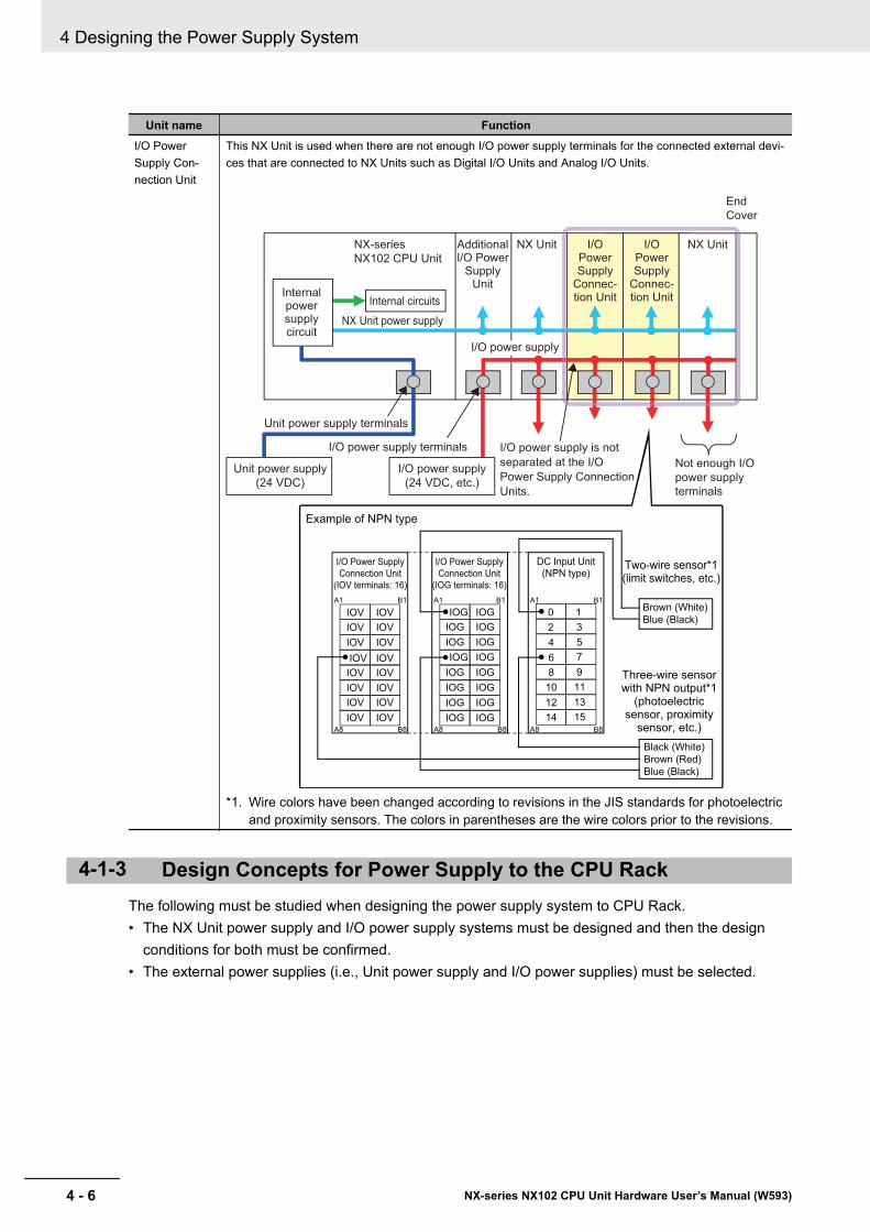
Unit name FunctionI/O PowerSupply Con-nection Unit
This NX Unit is used when there are not enough I/O power supply terminals for the connected external devi-ces that are connected to NX Units such as Digital I/O Units and Analog I/O Units.
End
Cover
Not enough I/O
power supply
terminals
I/O power supply is not
separated at the I/O
Power Supply Connection
Units.
NX Unit NX UnitAdditional I/O Power
Supply Unit
I/O Power Supply
Connec-tion Unit
I/O Power Supply
Connec-tion Unit
NX-series
NX102 CPU Unit
Unit power supply terminals
Internal power supply circuit
Internal circuits
NX Unit power supply
Unit power supply
(24 VDC)
I/O power supply terminals
I/O power supply
A1
A8
B1
B8
A1
A8
B1
B8
A1
A8
B1
B8
IOV
IOV
IOV
IOV
IOV
IOV
IOV
IOV
IOV
IOV
IOV
IOV
IOV
IOV
IOV
IOV
IOG
IOG
IOG
IOG
IOG
IOG
IOG
IOG
IOG
IOG
IOG
IOG
IOG
IOG
IOG
IOG
1
9
7
5
3
13
11
15
0
8
6
4
2
12
10
14
Example of NPN type
I/O Power Supply
Connection Unit
(IOV terminals: 16)
I/O Power Supply
Connection Unit
(IOG terminals: 16)
DC Input Unit(NPN type)
Two-wire sensor*1(limit switches, etc.)
Brown (White)
Blue (Black)
Three-wire sensor with NPN output*1
(photoelectric sensor, proximity
sensor, etc.)
Black (White)
Brown (Red)
Blue (Black)
I/O power supply
(24 VDC, etc.)
*1. Wire colors have been changed according to revisions in the JIS standards for photoelectricand proximity sensors. The colors in parentheses are the wire colors prior to the revisions.
4-1-3 Design Concepts for Power Supply to the CPU RackThe following must be studied when designing the power supply system to CPU Rack.• The NX Unit power supply and I/O power supply systems must be designed and then the design
conditions for both must be confirmed.• The external power supplies (i.e., Unit power supply and I/O power supplies) must be selected.
4 Designing the Power Supply System
4 - 6 NX-series NX102 CPU Unit Hardware User’s Manual (W593)
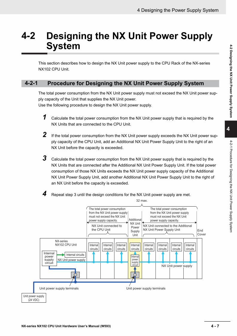
4-2 Designing the NX Unit Power SupplySystem
This section describes how to design the NX Unit power supply to the CPU Rack of the NX-seriesNX102 CPU Unit.
4-2-1 Procedure for Designing the NX Unit Power Supply SystemThe total power consumption from the NX Unit power supply must not exceed the NX Unit power sup-ply capacity of the Unit that supplies the NX Unit power.Use the following procedure to design the NX Unit power supply.
1 Calculate the total power consumption from the NX Unit power supply that is required by theNX Units that are connected to the CPU Unit.
2 If the total power consumption from the NX Unit power supply exceeds the NX Unit power sup-ply capacity of the CPU Unit, add an Additional NX Unit Power Supply Unit to the right of anNX Unit before the capacity is exceeded.
3 Calculate the total power consumption from the NX Unit power supply that is required by theNX Units that are connected after the Additional NX Unit Power Supply Unit. If the total powerconsumption of those NX Units exceeds the NX Unit power supply capacity of the AdditionalNX Unit Power Supply Unit, add another Additional NX Unit Power Supply Unit to the right ofan NX Unit before the capacity is exceeded.
4 Repeat step 3 until the design conditions for the NX Unit power supply are met.
NX-series NX102 CPU Unit
Unit power supply terminals
NX Unit connected to
the CPU Unit
NX Unit connected to the Additional
NX Unit Power Supply Unit
Unit power supply terminals
The total power consumption
from the NX Unit power supply
must not exceed the NX Unit
power supply capacity.
The total power consumption
from the NX Unit power supply
must not exceed the NX Unit
power supply capacity.
Internal circuits
NX Unit power supply
Internal
circuits
NX Unit power supply
Internal power supply circuit
32 max.
Additional
NX Unit
Power
Supply
Unit
End
Cover
Internal power supply circuit
Unit power supply
(24 VDC)
Internal
circuits
Internal
circuits
Internal
circuits
Internal
circuits
Internal
circuits
Internal
circuits
Internal
circuits
4 Designing the Power Supply System
4 - 7NX-series NX102 CPU Unit Hardware User’s Manual (W593)
4-2 Designing the N
X Unit Pow
er Supply System
4
4-2-1 Procedure for Designing the N
X Unit Pow
er Supply System
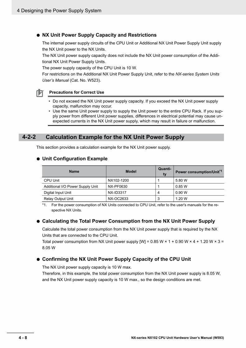
l NX Unit Power Supply Capacity and RestrictionsThe internal power supply circuits of the CPU Unit or Additional NX Unit Power Supply Unit supplythe NX Unit power to the NX Units.The NX Unit power supply capacity does not include the NX Unit power consumption of the Addi-tional NX Unit Power Supply Units.The power supply capacity of the CPU Unit is 10 W.For restrictions on the Additional NX Unit Power Supply Unit, refer to the NX-series System UnitsUser’s Manual (Cat. No. W523).
Precautions for Correct Use
• Do not exceed the NX Unit power supply capacity. If you exceed the NX Unit power supplycapacity, malfunction may occur.
• Use the same Unit power supply to supply the Unit power to the entire CPU Rack. If you sup-ply power from different Unit power supplies, differences in electrical potential may cause un-expected currents in the NX Unit power supply, which may result in failure or malfunction.
4-2-2 Calculation Example for the NX Unit Power SupplyThis section provides a calculation example for the NX Unit power supply.
l Unit Configuration Example
Name Model Quanti-ty Power consumption/Unit*1
CPU Unit NX102-1200 1 5.80 WAdditional I/O Power Supply Unit NX-PF0630 1 0.85 WDigital Input Unit NX-ID3317 4 0.90 WRelay Output Unit NX-OC2633 3 1.20 W
*1. For the power consumption of NX Units connected to CPU Unit, refer to the user's manuals for the re-spective NX Units.
l Calculating the Total Power Consumption from the NX Unit Power SupplyCalculate the total power consumption from the NX Unit power supply that is required by the NXUnits that are connected to the CPU Unit.Total power consumption from NX Unit power supply [W] = 0.85 W × 1 + 0.90 W × 4 + 1.20 W × 3 =8.05 W
l Confirming the NX Unit Power Supply Capacity of the CPU UnitThe NX Unit power supply capacity is 10 W max.Therefore, in this example, the total power consumption from the NX Unit power supply is 8.05 W,and the NX Unit power supply capacity is 10 W max., so the design conditions are met.
4 Designing the Power Supply System
4 - 8 NX-series NX102 CPU Unit Hardware User’s Manual (W593)
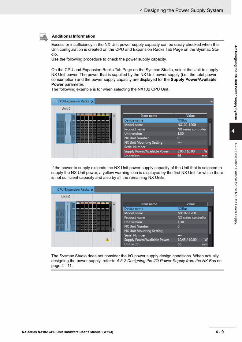
Additional Information
Excess or insufficiency in the NX Unit power supply capacity can be easily checked when theUnit configuration is created on the CPU and Expansion Racks Tab Page on the Sysmac Stu-dio.Use the following procedure to check the power supply capacity.
On the CPU and Expansion Racks Tab Page on the Sysmac Studio, select the Unit to supplyNX Unit power. The power that is supplied by the NX Unit power supply (i.e., the total powerconsumption) and the power supply capacity are displayed for the Supply Power/AvailablePower parameter.The following example is for when selecting the NX102 CPU Unit.
If the power to supply exceeds the NX Unit power supply capacity of the Unit that is selected tosupply the NX Unit power, a yellow warning icon is displayed by the first NX Unit for which thereis not sufficient capacity and also by all the remaining NX Units.
The Sysmac Studio does not consider the I/O power supply design conditions. When actuallydesigning the power supply, refer to 4-3-2 Designing the I/O Power Supply from the NX Bus onpage 4 - 11.
4 Designing the Power Supply System
4 - 9NX-series NX102 CPU Unit Hardware User’s Manual (W593)
4-2 Designing the N
X Unit Pow
er Supply System
4
4-2-2 Calculation Exam
ple for the NX U
nit Power Supply
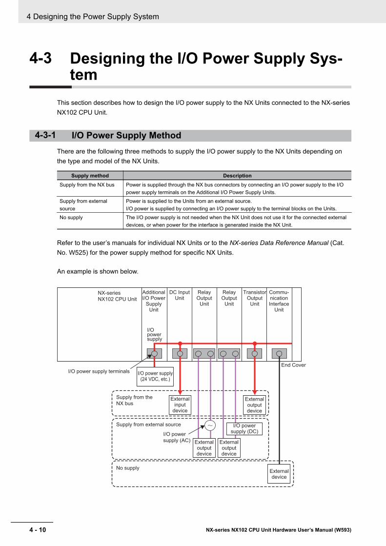
4-3 Designing the I/O Power Supply Sys-tem
This section describes how to design the I/O power supply to the NX Units connected to the NX-seriesNX102 CPU Unit.
4-3-1 I/O Power Supply MethodThere are the following three methods to supply the I/O power supply to the NX Units depending onthe type and model of the NX Units.
Supply method DescriptionSupply from the NX bus Power is supplied through the NX bus connectors by connecting an I/O power supply to the I/O
power supply terminals on the Additional I/O Power Supply Units.Supply from externalsource
Power is supplied to the Units from an external source.I/O power is supplied by connecting an I/O power supply to the terminal blocks on the Units.
No supply The I/O power supply is not needed when the NX Unit does not use it for the connected externaldevices, or when power for the interface is generated inside the NX Unit.
Refer to the user’s manuals for individual NX Units or to the NX-series Data Reference Manual (Cat.No. W525) for the power supply method for specific NX Units.
An example is shown below.
NX-series
NX102 CPU Unit
I/O power
supply (AC)
No supply
I/O power supply
Additional I/O Power
Supply Unit
DC Input Unit
Relay Output
Unit
Relay Output
Unit
Transistor Output
Unit
Commu-nication Interface
Unit
Supply from external source
Supply from the
NX bus
External device
External output device
External output device
External input
device
External output device
I/O power supply (DC)
I/O power supply terminals I/O power supply(24 VDC, etc.)
End Cover
4 Designing the Power Supply System
4 - 10 NX-series NX102 CPU Unit Hardware User’s Manual (W593)
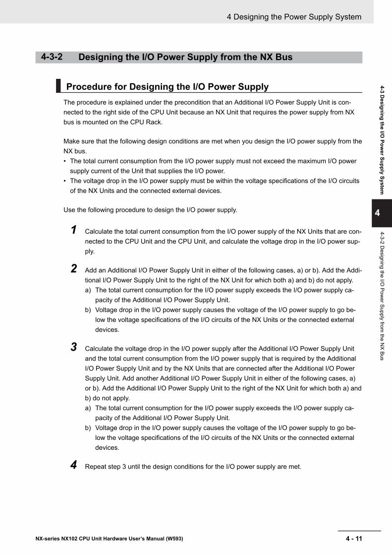
4-3-2 Designing the I/O Power Supply from the NX Bus
Procedure for Designing the I/O Power SupplyThe procedure is explained under the precondition that an Additional I/O Power Supply Unit is con-nected to the right side of the CPU Unit because an NX Unit that requires the power supply from NXbus is mounted on the CPU Rack.
Make sure that the following design conditions are met when you design the I/O power supply from theNX bus.• The total current consumption from the I/O power supply must not exceed the maximum I/O power
supply current of the Unit that supplies the I/O power.• The voltage drop in the I/O power supply must be within the voltage specifications of the I/O circuits
of the NX Units and the connected external devices.
Use the following procedure to design the I/O power supply.
1 Calculate the total current consumption from the I/O power supply of the NX Units that are con-nected to the CPU Unit and the CPU Unit, and calculate the voltage drop in the I/O power sup-ply.
2 Add an Additional I/O Power Supply Unit in either of the following cases, a) or b). Add the Addi-tional I/O Power Supply Unit to the right of the NX Unit for which both a) and b) do not apply.a) The total current consumption for the I/O power supply exceeds the I/O power supply ca-
pacity of the Additional I/O Power Supply Unit.b) Voltage drop in the I/O power supply causes the voltage of the I/O power supply to go be-
low the voltage specifications of the I/O circuits of the NX Units or the connected externaldevices.
3 Calculate the voltage drop in the I/O power supply after the Additional I/O Power Supply Unitand the total current consumption from the I/O power supply that is required by the AdditionalI/O Power Supply Unit and by the NX Units that are connected after the Additional I/O PowerSupply Unit. Add another Additional I/O Power Supply Unit in either of the following cases, a)or b). Add the Additional I/O Power Supply Unit to the right of the NX Unit for which both a) andb) do not apply.a) The total current consumption for the I/O power supply exceeds the I/O power supply ca-
pacity of the Additional I/O Power Supply Unit.b) Voltage drop in the I/O power supply causes the voltage of the I/O power supply to go be-
low the voltage specifications of the I/O circuits of the NX Units or the connected externaldevices.
4 Repeat step 3 until the design conditions for the I/O power supply are met.
4 Designing the Power Supply System
4 - 11NX-series NX102 CPU Unit Hardware User’s Manual (W593)
4-3 Designing the I/O
Power Supply System
4
4-3-2 Designing the I/O
Power Supply from
the NX Bus
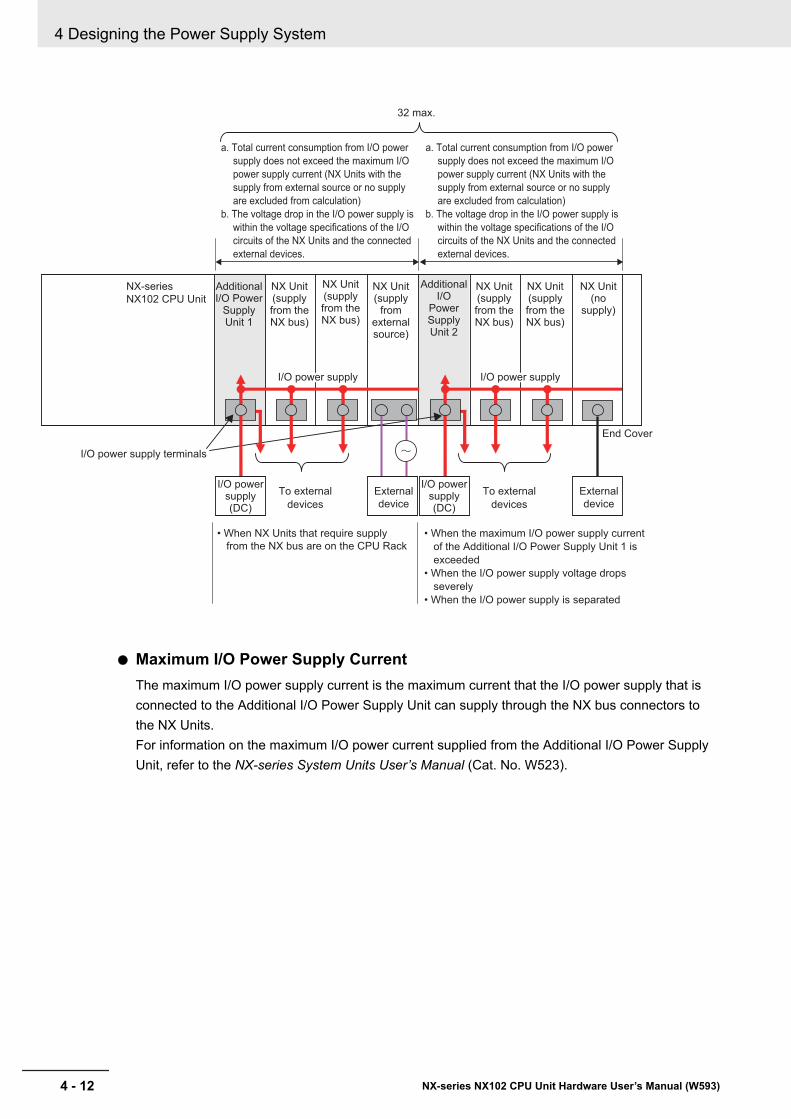
NX-series
NX102 CPU Unit
a. Total current consumption from I/O power
supply does not exceed the maximum I/O
power supply current (NX Units with the
supply from external source or no supply
are excluded from calculation)
b. The voltage drop in the I/O power supply is
within the voltage specifications of the I/O
circuits of the NX Units and the connected
external devices.
Additional I/O Power
Supply Unit 1
NX Unit(no
supply)
Additional I/O
Power Supply Unit 2
NX Unit(supply from the NX bus)
NX Unit(supply from the NX bus)
NX Unit(supply from the NX bus)
NX Unit(supply from the NX bus)
NX Unit(supply
from external source)
• When NX Units that require supply
from the NX bus are on the CPU Rack
• When the maximum I/O power supply current
of the Additional I/O Power Supply Unit 1 is
exceeded
• When the I/O power supply voltage drops
severely
• When the I/O power supply is separated
32 max.
External
device
To external
devices
To external
devices
End Cover
I/O power supply terminals
External
device
I/O power supply(DC)
I/O power supply(DC)
I/O power supply I/O power supply
l Maximum I/O Power Supply CurrentThe maximum I/O power supply current is the maximum current that the I/O power supply that isconnected to the Additional I/O Power Supply Unit can supply through the NX bus connectors tothe NX Units.For information on the maximum I/O power current supplied from the Additional I/O Power SupplyUnit, refer to the NX-series System Units User’s Manual (Cat. No. W523).
4 Designing the Power Supply System
4 - 12 NX-series NX102 CPU Unit Hardware User’s Manual (W593)
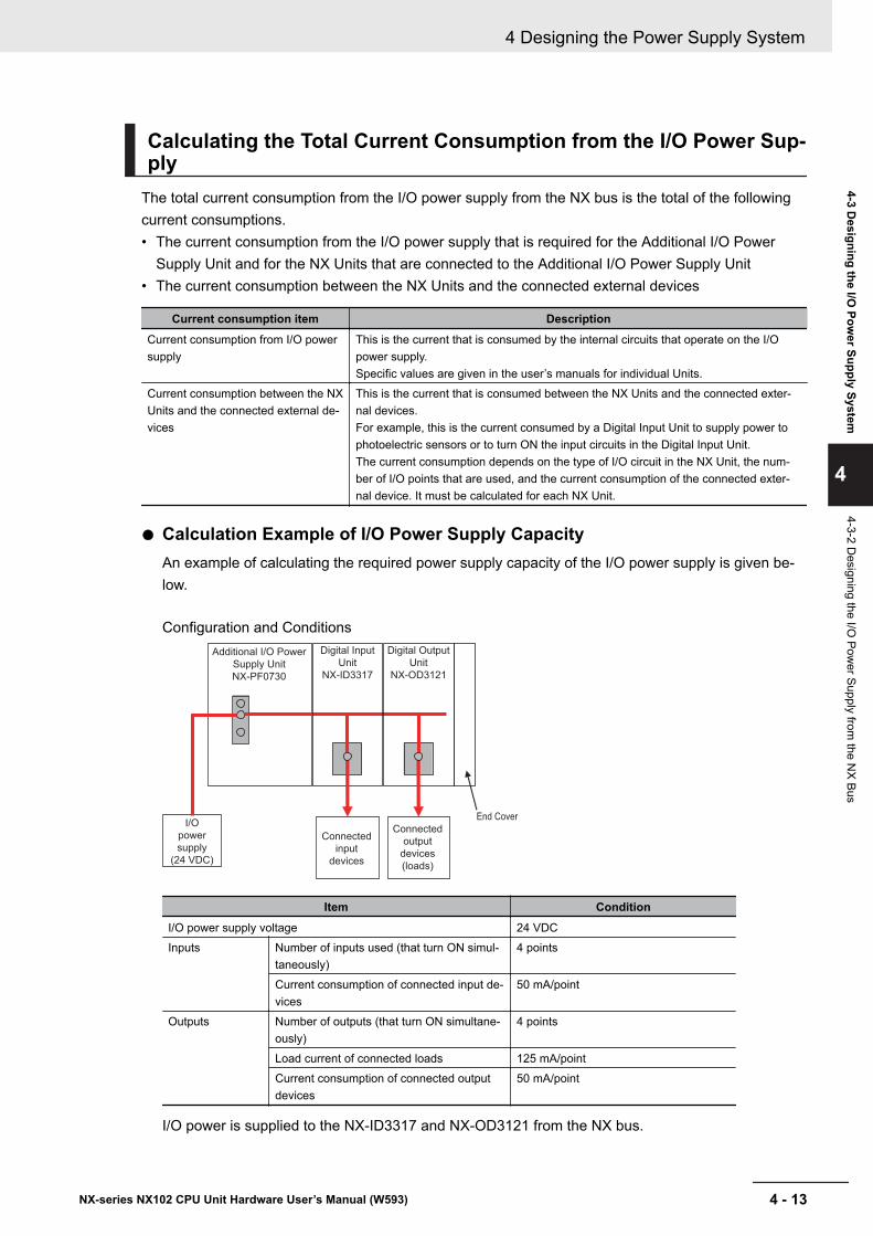
Calculating the Total Current Consumption from the I/O Power Sup-ply
The total current consumption from the I/O power supply from the NX bus is the total of the followingcurrent consumptions.• The current consumption from the I/O power supply that is required for the Additional I/O Power
Supply Unit and for the NX Units that are connected to the Additional I/O Power Supply Unit• The current consumption between the NX Units and the connected external devices
Current consumption item DescriptionCurrent consumption from I/O powersupply
This is the current that is consumed by the internal circuits that operate on the I/Opower supply.Specific values are given in the user’s manuals for individual Units.
Current consumption between the NXUnits and the connected external de-vices
This is the current that is consumed between the NX Units and the connected exter-nal devices.For example, this is the current consumed by a Digital Input Unit to supply power tophotoelectric sensors or to turn ON the input circuits in the Digital Input Unit.The current consumption depends on the type of I/O circuit in the NX Unit, the num-ber of I/O points that are used, and the current consumption of the connected exter-nal device. It must be calculated for each NX Unit.
l Calculation Example of I/O Power Supply CapacityAn example of calculating the required power supply capacity of the I/O power supply is given be-low.
Configuration and Conditions
I/O
power
supply
(24 VDC)
Additional I/O Power
Supply Unit
NX-PF0730
End Cover
Digital Input
Unit
NX-ID3317
Connected
input
devices
Digital Output
Unit
NX-OD3121
Connected
output
devices
(loads)
Item ConditionI/O power supply voltage 24 VDCInputs Number of inputs used (that turn ON simul-
taneously)4 points
Current consumption of connected input de-vices
50 mA/point
Outputs Number of outputs (that turn ON simultane-ously)
4 points
Load current of connected loads 125 mA/pointCurrent consumption of connected outputdevices
50 mA/point
I/O power is supplied to the NX-ID3317 and NX-OD3121 from the NX bus.
4 Designing the Power Supply System
4 - 13NX-series NX102 CPU Unit Hardware User’s Manual (W593)
4-3 Designing the I/O
Power Supply System
4
4-3-2 Designing the I/O
Power Supply from
the NX Bus
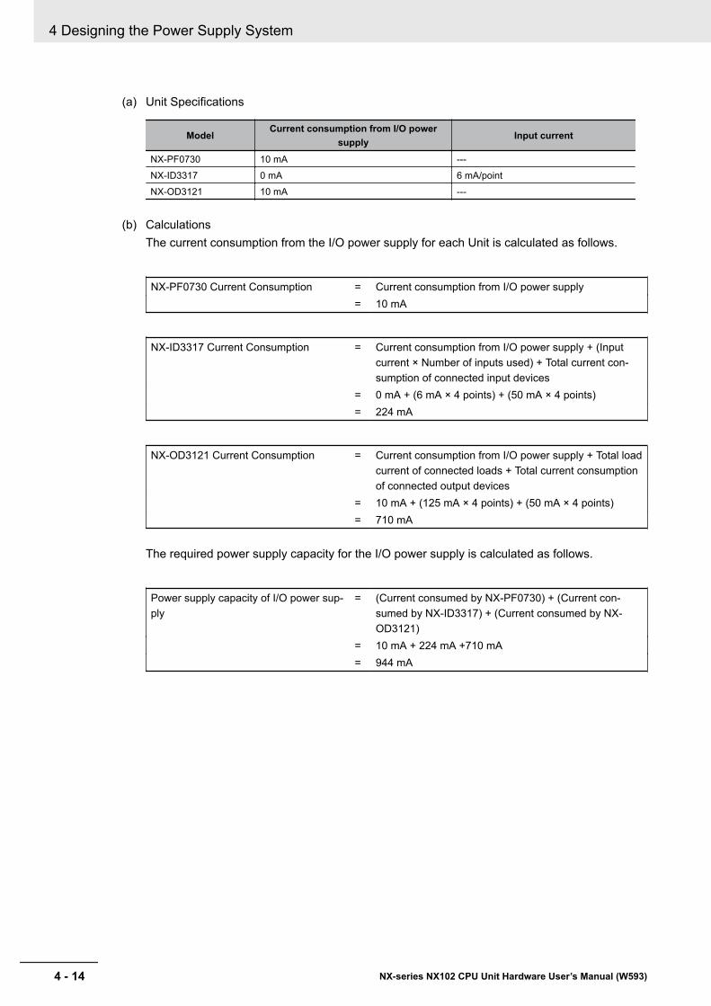
(a) Unit Specifications
ModelCurrent consumption from I/O power
supplyInput current
NX-PF0730 10 mA ---NX-ID3317 0 mA 6 mA/pointNX-OD3121 10 mA ---
(b) CalculationsThe current consumption from the I/O power supply for each Unit is calculated as follows.
NX-PF0730 Current Consumption = Current consumption from I/O power supply= 10 mA
NX-ID3317 Current Consumption = Current consumption from I/O power supply + (Inputcurrent × Number of inputs used) + Total current con-sumption of connected input devices
= 0 mA + (6 mA × 4 points) + (50 mA × 4 points)= 224 mA
NX-OD3121 Current Consumption = Current consumption from I/O power supply + Total loadcurrent of connected loads + Total current consumptionof connected output devices
= 10 mA + (125 mA × 4 points) + (50 mA × 4 points)= 710 mA
The required power supply capacity for the I/O power supply is calculated as follows.
Power supply capacity of I/O power sup-ply
= (Current consumed by NX-PF0730) + (Current con-sumed by NX-ID3317) + (Current consumed by NX-OD3121)
= 10 mA + 224 mA +710 mA= 944 mA
4 Designing the Power Supply System
4 - 14 NX-series NX102 CPU Unit Hardware User’s Manual (W593)
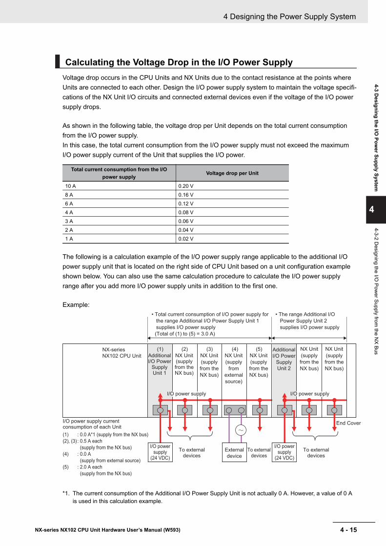
Calculating the Voltage Drop in the I/O Power SupplyVoltage drop occurs in the CPU Units and NX Units due to the contact resistance at the points whereUnits are connected to each other. Design the I/O power supply system to maintain the voltage specifi-cations of the NX Unit I/O circuits and connected external devices even if the voltage of the I/O powersupply drops.
As shown in the following table, the voltage drop per Unit depends on the total current consumptionfrom the I/O power supply.In this case, the total current consumption from the I/O power supply must not exceed the maximumI/O power supply current of the Unit that supplies the I/O power.
Total current consumption from the I/Opower supply
Voltage drop per Unit
10 A 0.20 V8 A 0.16 V6 A 0.12 V4 A 0.08 V3 A 0.06 V2 A 0.04 V1 A 0.02 V
The following is a calculation example of the I/O power supply range applicable to the additional I/Opower supply unit that is located on the right side of CPU Unit based on a unit configuration exampleshown below. You can also use the same calculation procedure to calculate the I/O power supplyrange after you add more I/O power supply units in addition to the first one.
Example:
I/O power supply current consumption of each Unit
(1)
(2), (3)
(4)
(5)
: 0.0 A*1 (supply from the NX bus)
: 0.5 A each
(supply from the NX bus)
: 0.0 A
(supply from external source)
: 2.0 A each
(supply from the NX bus)
NX-series
NX102 CPU Unit
• Total current consumption of I/O power supply for
the range Additional I/O Power Supply Unit 1
supplies I/O power supply
(Total of (1) to (5) = 3.0 A)
• The range Additional I/O
Power Supply Unit 2
supplies I/O power supply
Additional I/O Power
Supply Unit 1
Additional
I/O Power
Supply
Unit 2
NX Unit(supply from the NX bus)
NX Unit
(supply
from the
NX bus)
NX Unit
(supply
from the
NX bus)
NX Unit
(supply
from the
NX bus)
NX Unit
(supply
from the
NX bus)
NX Unit
(supply
from
external
source)
End Cover
To external devices
To external devices
To external devices
External
device
I/O power supply
(24 VDC)
I/O power supply
(24 VDC)
(1) (2) (3) (4) (5)
I/O power supply I/O power supply
*1. The current consumption of the Additional I/O Power Supply Unit is not actually 0 A. However, a value of 0 Ais used in this calculation example.
4 Designing the Power Supply System
4 - 15NX-series NX102 CPU Unit Hardware User’s Manual (W593)
4-3 Designing the I/O
Power Supply System
4
4-3-2 Designing the I/O
Power Supply from
the NX Bus
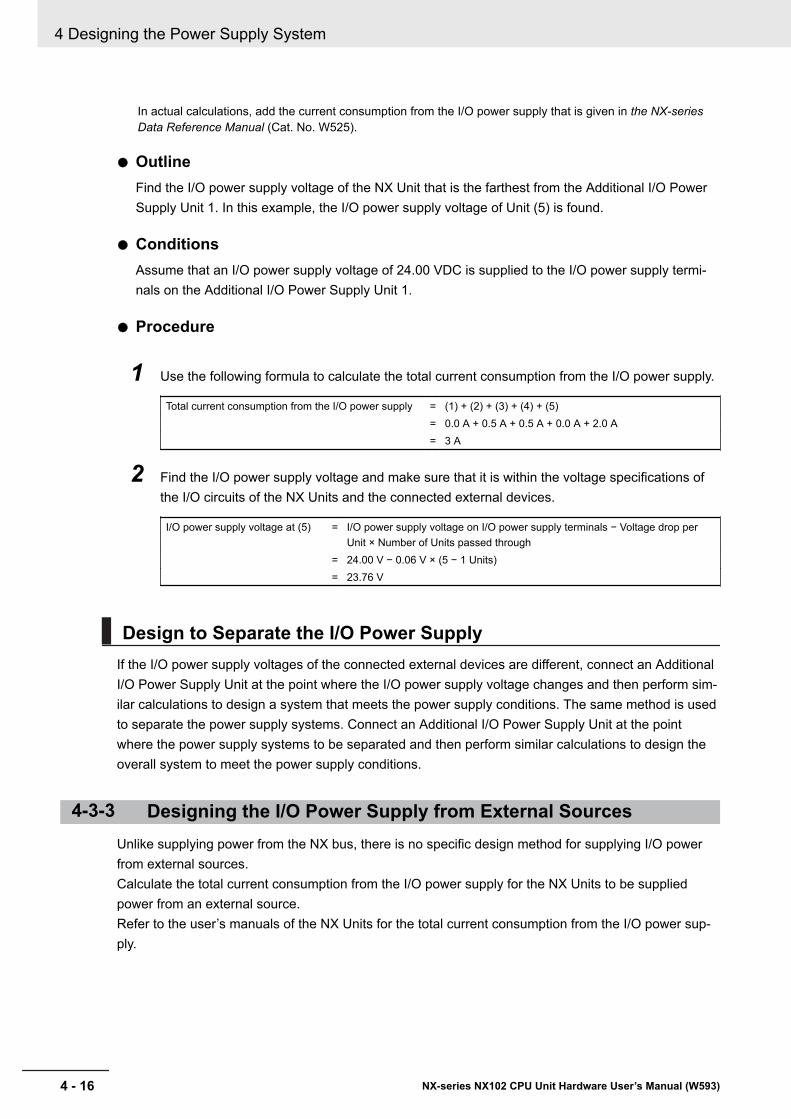
In actual calculations, add the current consumption from the I/O power supply that is given in the NX-seriesData Reference Manual (Cat. No. W525).
l OutlineFind the I/O power supply voltage of the NX Unit that is the farthest from the Additional I/O PowerSupply Unit 1. In this example, the I/O power supply voltage of Unit (5) is found.
l ConditionsAssume that an I/O power supply voltage of 24.00 VDC is supplied to the I/O power supply termi-nals on the Additional I/O Power Supply Unit 1.
l Procedure
1 Use the following formula to calculate the total current consumption from the I/O power supply.
Total current consumption from the I/O power supply = (1) + (2) + (3) + (4) + (5)= 0.0 A + 0.5 A + 0.5 A + 0.0 A + 2.0 A= 3 A
2 Find the I/O power supply voltage and make sure that it is within the voltage specifications ofthe I/O circuits of the NX Units and the connected external devices.
I/O power supply voltage at (5) = I/O power supply voltage on I/O power supply terminals − Voltage drop perUnit × Number of Units passed through
= 24.00 V − 0.06 V × (5 − 1 Units)= 23.76 V
Design to Separate the I/O Power SupplyIf the I/O power supply voltages of the connected external devices are different, connect an AdditionalI/O Power Supply Unit at the point where the I/O power supply voltage changes and then perform sim-ilar calculations to design a system that meets the power supply conditions. The same method is usedto separate the power supply systems. Connect an Additional I/O Power Supply Unit at the pointwhere the power supply systems to be separated and then perform similar calculations to design theoverall system to meet the power supply conditions.
4-3-3 Designing the I/O Power Supply from External SourcesUnlike supplying power from the NX bus, there is no specific design method for supplying I/O powerfrom external sources.Calculate the total current consumption from the I/O power supply for the NX Units to be suppliedpower from an external source.Refer to the user’s manuals of the NX Units for the total current consumption from the I/O power sup-ply.
4 Designing the Power Supply System
4 - 16 NX-series NX102 CPU Unit Hardware User’s Manual (W593)
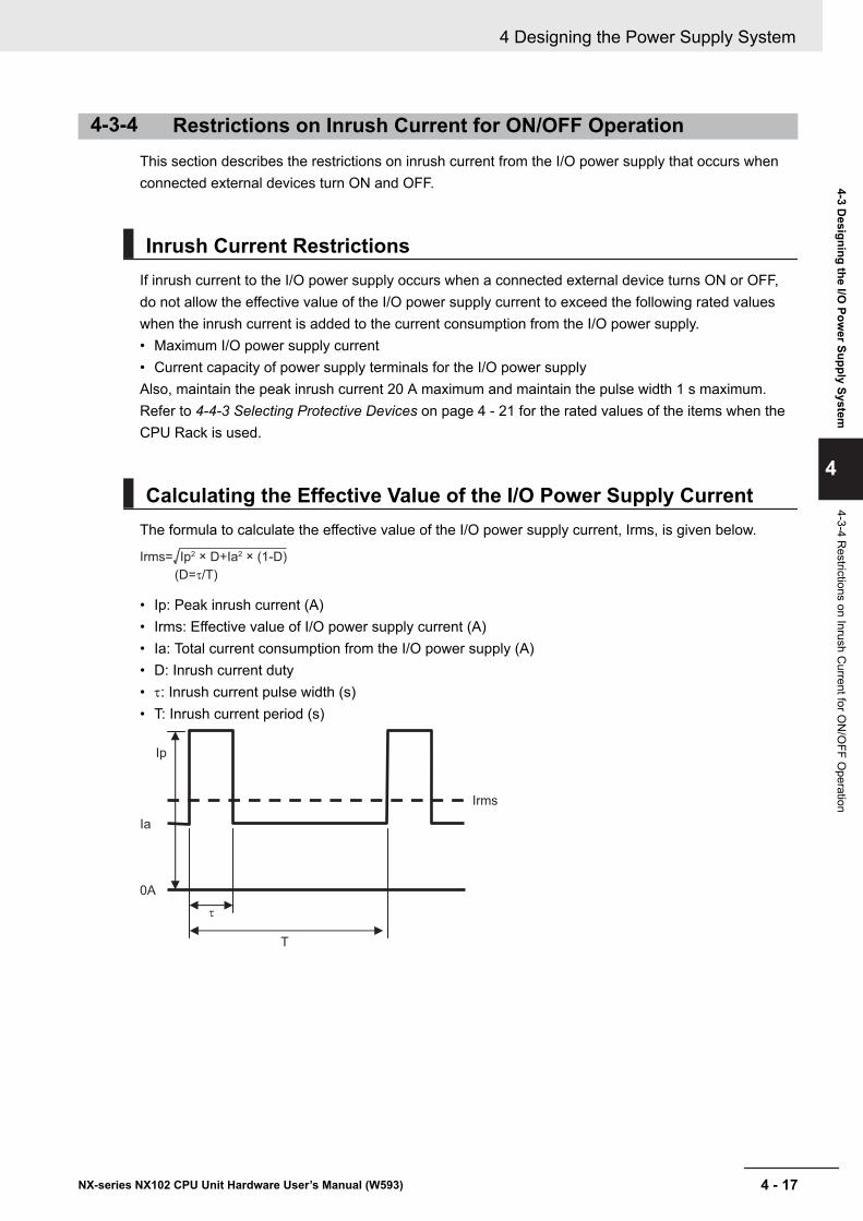
4-3-4 Restrictions on Inrush Current for ON/OFF OperationThis section describes the restrictions on inrush current from the I/O power supply that occurs whenconnected external devices turn ON and OFF.
Inrush Current RestrictionsIf inrush current to the I/O power supply occurs when a connected external device turns ON or OFF,do not allow the effective value of the I/O power supply current to exceed the following rated valueswhen the inrush current is added to the current consumption from the I/O power supply.• Maximum I/O power supply current• Current capacity of power supply terminals for the I/O power supplyAlso, maintain the peak inrush current 20 A maximum and maintain the pulse width 1 s maximum.Refer to 4-4-3 Selecting Protective Devices on page 4 - 21 for the rated values of the items when theCPU Rack is used.
Calculating the Effective Value of the I/O Power Supply CurrentThe formula to calculate the effective value of the I/O power supply current, Irms, is given below.
Irms= Ip2 × D+Ia2 × (1-D)
(D=τ/T)
• Ip: Peak inrush current (A)• Irms: Effective value of I/O power supply current (A)• Ia: Total current consumption from the I/O power supply (A)• D: Inrush current duty• t: Inrush current pulse width (s)• T: Inrush current period (s)
Ip
Ia
Irms
τ
T
0A
4 Designing the Power Supply System
4 - 17NX-series NX102 CPU Unit Hardware User’s Manual (W593)
4-3 Designing the I/O
Power Supply System
4
4-3-4 Restrictions on Inrush C
urrent for ON
/OFF O
peration
4-4 Selecting External Power Suppliesand Protective Devices
This section describes how to select the Unit power supply and the I/O power supply which are theexternal power supplies for the CPU Rack, and how to select the protective devices.
4-4-1 Selecting the Unit Power SupplyThis section describes how to select the Unit power supply for the CPU Rack.
Recommended Power SuppliesUse an SELV power supply that meets the following conditions for the Unit power supply.• Has overcurrent protection.• Has double or reinforced insulation between the input and output.• Has an output voltage of 24 VDC (20.4 to 28.8 VDC).Recommended Power Supplies: S8VK-S Series (manufactured by OMRON)
Calculating the Required Power Supply Capacity of the Unit PowerSupply
l FormulaThis section describes how to calculate the required capacity of the Unit power supply for the CPURack.
Required capacity of the Unit power supply forthe CPU Rack
= Total of required Unit power supply capacity foreach block
Use the following formula to calculate the required Unit power supply capacity for each block in theCPU Rack.Required Unit power supply capacity of the CPU Unit block = (A) + (B)/(C)Required Unit power supply capacity of an Additional NX Unit Power Supply Unit block = ((D) +(E))/(F)
(A) Unit power consumption of the CPU Unit(B) Total NX Unit power consumption of NX Units that are connected to the CPU Unit(C) NX Unit power supply efficiency of the CPU Unit(D) NX Unit power consumption of the Additional NX Unit Power Supply Unit(E) Total NX Unit power consumption of NX Units that are connected to the Additional NX Unit
Power Supply Unit(F) NX Unit power supply efficiency of the Additional NX Unit Power Supply Unit
4 Designing the Power Supply System
4 - 18 NX-series NX102 CPU Unit Hardware User’s Manual (W593)
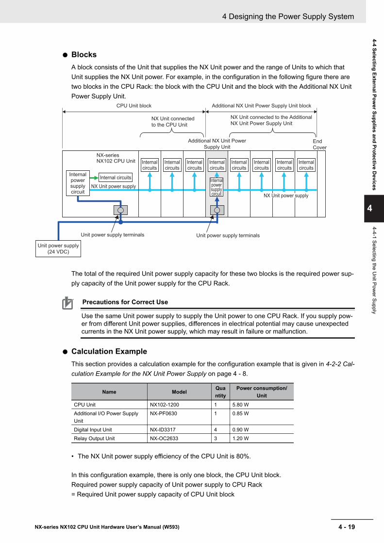
l BlocksA block consists of the Unit that supplies the NX Unit power and the range of Units to which thatUnit supplies the NX Unit power. For example, in the configuration in the following figure there aretwo blocks in the CPU Rack: the block with the CPU Unit and the block with the Additional NX UnitPower Supply Unit.
Internal circuits
End
Cover
NX Unit power supply
Internal circuits
Internal circuits
Internal circuits
NX Unit power supply
Internal power supply circuit
Unit power supply terminals
CPU Unit block Additional NX Unit Power Supply Unit block
NX Unit connected
to the CPU Unit
NX Unit connected to the Additional
NX Unit Power Supply Unit
Additional NX Unit Power
Supply Unit
Internal power supply circuit
Unit power supply terminals
NX-series NX102 CPU Unit
Unit power supply
(24 VDC)
Internal circuits
Internal circuits
Internal circuits
Internal circuits
Internal circuits
The total of the required Unit power supply capacity for these two blocks is the required power sup-ply capacity of the Unit power supply for the CPU Rack.
Precautions for Correct Use
Use the same Unit power supply to supply the Unit power to one CPU Rack. If you supply pow-er from different Unit power supplies, differences in electrical potential may cause unexpectedcurrents in the NX Unit power supply, which may result in failure or malfunction.
l Calculation ExampleThis section provides a calculation example for the configuration example that is given in 4-2-2 Cal-culation Example for the NX Unit Power Supply on page 4 - 8.
Name ModelQuantity
Power consumption/Unit
CPU Unit NX102-1200 1 5.80 WAdditional I/O Power SupplyUnit
NX-PF0630 1 0.85 W
Digital Input Unit NX-ID3317 4 0.90 WRelay Output Unit NX-OC2633 3 1.20 W
• The NX Unit power supply efficiency of the CPU Unit is 80%.
In this configuration example, there is only one block, the CPU Unit block.Required power supply capacity of Unit power supply to CPU Rack= Required Unit power supply capacity of CPU Unit block
4 Designing the Power Supply System
4 - 19NX-series NX102 CPU Unit Hardware User’s Manual (W593)
4-4 Selecting External Power Supplies and Protective D
evices
4
4-4-1 Selecting the Unit Pow
er Supply
= (CPU Unit power consumption + Total power consumption from NX Unit power supply of NXUnits connected to CPU Unit)/NX Unit power supply efficiency of CPU Unit= 5.80 W + (0.85 W × 1 + 0.90 W × 4 + 1.20 W × 3)/0.8= Approx. 15.9 W
The above is the constant power consumption during operation. When you select the power supply,consider the inrush current that will flow when the power is turned ON.Refer to Electrical and Mechanical Specifications on page 3 - 3 under 3-1-1 Models and Specifica-tions on page 3 - 2 for information on surge current specifications.
Precautions for Safe Use
Select an external power supply with sufficient capacity by considering the power supply ca-pacity or inrush current when the power is turned ON. Otherwise, the external power supplymay not be turned ON or it may malfunction due to unstable voltage.
4-4-2 Selecting the I/O Power SuppliesThis section describes how to select the I/O power supplies for the CPU Rack.
Recommended Power SuppliesUse an SELV power supply that meets the following conditions for the I/O power supply.• Has overcurrent protection.• Has double or reinforced insulation between the input and output.• Has an output voltage of 5 to 24 VDC (4.5 to 28.8 VDC).*1*1. Use an output voltage that is appropriate for the I/O circuits of the NX Units and the connected external devi-
ces.Recommended Power Supplies: S8VK-S Series (manufactured by OMRON)
Calculating the Required Power Supply Capacity of the I/O PowerSupply for NX Units
Use the calculation method that is described in 4-3-2 Designing the I/O Power Supply from the NXBus on page 4 - 11 and calculate the total current consumption from the I/O power supply and the re-quired power supply capacity of the I/O power supply.Unlike the Unit power supply, it is not necessary to use only one I/O power supply to supply power toall NX Units on the CPU Rack.
Precautions for Safe Use
Select an external power supply with sufficient capacity by considering the power supply ca-pacity or inrush current when the power is turned ON. Otherwise, the external power supplymay not be turned ON or it may malfunction due to unstable voltage.
4 Designing the Power Supply System
4 - 20 NX-series NX102 CPU Unit Hardware User’s Manual (W593)
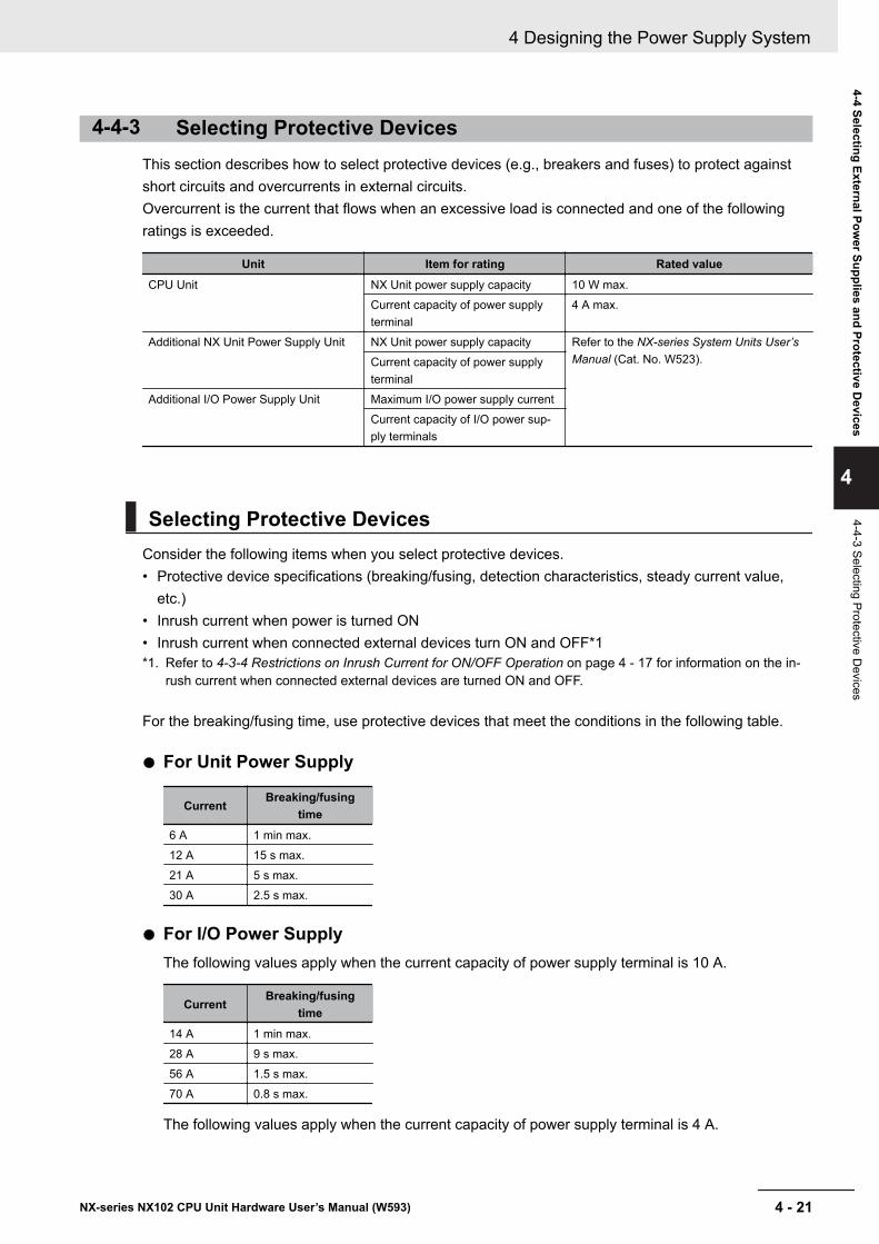
4-4-3 Selecting Protective DevicesThis section describes how to select protective devices (e.g., breakers and fuses) to protect againstshort circuits and overcurrents in external circuits.Overcurrent is the current that flows when an excessive load is connected and one of the followingratings is exceeded.
Unit Item for rating Rated valueCPU Unit NX Unit power supply capacity 10 W max.
Current capacity of power supplyterminal
4 A max.
Additional NX Unit Power Supply Unit NX Unit power supply capacity Refer to the NX-series System Units User’sManual (Cat. No. W523).Current capacity of power supply
terminalAdditional I/O Power Supply Unit Maximum I/O power supply current
Current capacity of I/O power sup-ply terminals
Selecting Protective DevicesConsider the following items when you select protective devices.• Protective device specifications (breaking/fusing, detection characteristics, steady current value,
etc.)• Inrush current when power is turned ON• Inrush current when connected external devices turn ON and OFF*1*1. Refer to 4-3-4 Restrictions on Inrush Current for ON/OFF Operation on page 4 - 17 for information on the in-
rush current when connected external devices are turned ON and OFF.
For the breaking/fusing time, use protective devices that meet the conditions in the following table.
l For Unit Power Supply
CurrentBreaking/fusing
time6 A 1 min max.12 A 15 s max.21 A 5 s max.30 A 2.5 s max.
l For I/O Power SupplyThe following values apply when the current capacity of power supply terminal is 10 A.
CurrentBreaking/fusing
time14 A 1 min max.28 A 9 s max.56 A 1.5 s max.70 A 0.8 s max.
The following values apply when the current capacity of power supply terminal is 4 A.
4 Designing the Power Supply System
4 - 21NX-series NX102 CPU Unit Hardware User’s Manual (W593)
4-4 Selecting External Power Supplies and Protective D
evices
4
4-4-3 Selecting Protective Devices
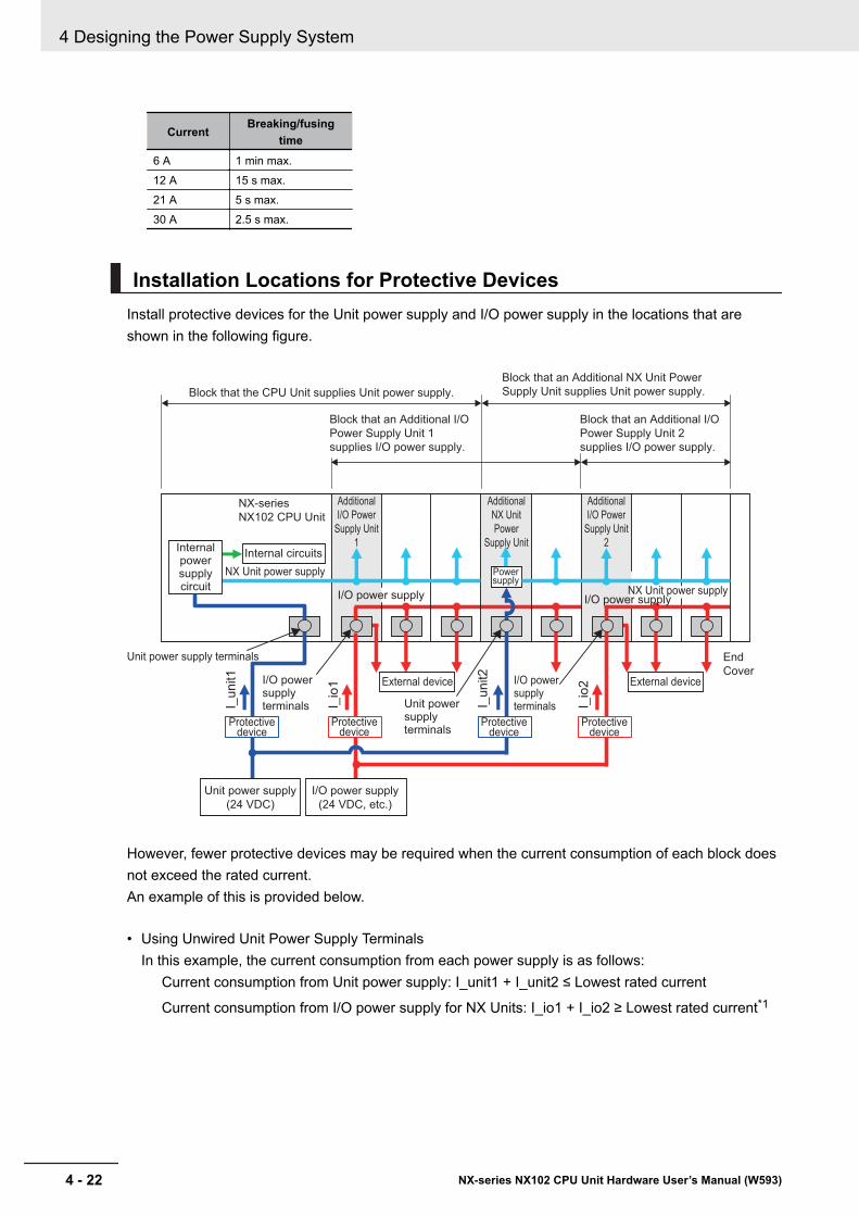
CurrentBreaking/fusing
time6 A 1 min max.12 A 15 s max.21 A 5 s max.30 A 2.5 s max.
Installation Locations for Protective DevicesInstall protective devices for the Unit power supply and I/O power supply in the locations that areshown in the following figure.
External device
End
Cover
Internal circuits
NX Unit power supply
Unit power supply terminals
Internal power supply circuit
NX-series
NX102 CPU Unit
I_u
nit1
I_u
nit2
Protective device
I_io
1
I_io
2I/O power supply
Block that the CPU Unit supplies Unit power supply.
Block that an Additional I/O
Power Supply Unit 1
supplies I/O power supply.
Block that an Additional I/O
Power Supply Unit 2
supplies I/O power supply.
Block that an Additional NX Unit Power
Supply Unit supplies Unit power supply.
External device
Additional
I/O Power
Supply Unit
1
Additional
I/O Power
Supply Unit
2
NX Unit power supply
Unit power supply terminals
I/O power supply terminals
I/O power supply terminals
Additional
NX Unit
Power
Supply Unit
Protective device
Protective device
Protective device
Power supply
I/O power supply
Unit power supply
(24 VDC)
I/O power supply
(24 VDC, etc.)
However, fewer protective devices may be required when the current consumption of each block doesnot exceed the rated current.An example of this is provided below.
• Using Unwired Unit Power Supply TerminalsIn this example, the current consumption from each power supply is as follows:
Current consumption from Unit power supply: I_unit1 + I_unit2 ≤ Lowest rated current
Current consumption from I/O power supply for NX Units: I_io1 + I_io2 ≥ Lowest rated current*1
4 Designing the Power Supply System
4 - 22 NX-series NX102 CPU Unit Hardware User’s Manual (W593)
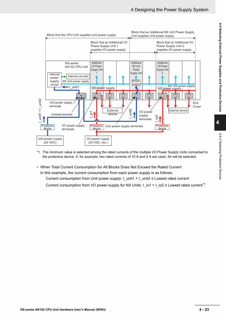
Internal circuits
NX Unit power supply
NX-series
NX102 CPU Unit
Unit power supply
(24 VDC)
I_u
nit1
+ I
_u
nit2
End
Cover
I/O power supply
I/O power supply
terminals
External
device
External device
I_u
nit2
I_io
1
Unit power supply terminals
I_io
2
Additional I/O Power
Supply Unit 1
Additional I/O Power
Supply Unit 2
Additional NX Unit Power
Supply Unit
Protective device
Protective device
Protective device
Unit power supply
terminals
Unwired terminal
I_unit1
I/O power
supply
terminals
Block that the CPU Unit supplies Unit power supply.Block that an Additional NX Unit Power Supply
Unit supplies Unit power supply.
Block that an Additional I/O
Power Supply Unit 1
supplies I/O power supply.
Block that an Additional I/O
Power Supply Unit 2
supplies I/O power supply.
NX Unit power supply
Internal power supply circuit
Power supply
I/O power supply
(24 VDC, etc.)
I/O power supply
*1. The minimum value is selected among the rated currents of the multiple I/O Power Supply Units connected tothe protective device. If, for example, two rated currents of 10 A and 4 A are used, 4A will be selected.
• When Total Current Consumption for All Blocks Does Not Exceed the Rated CurrentIn this example, the current consumption from each power supply is as follows:
Current consumption from Unit power supply: I_unit1 + I_unit2 ≤ Lowest rated current
Current consumption from I/O power supply for NX Units: I_io1 + I_io2 ≤ Lowest rated current*1
4 Designing the Power Supply System
4 - 23NX-series NX102 CPU Unit Hardware User’s Manual (W593)
4-4 Selecting External Power Supplies and Protective D
evices
4
4-4-3 Selecting Protective Devices
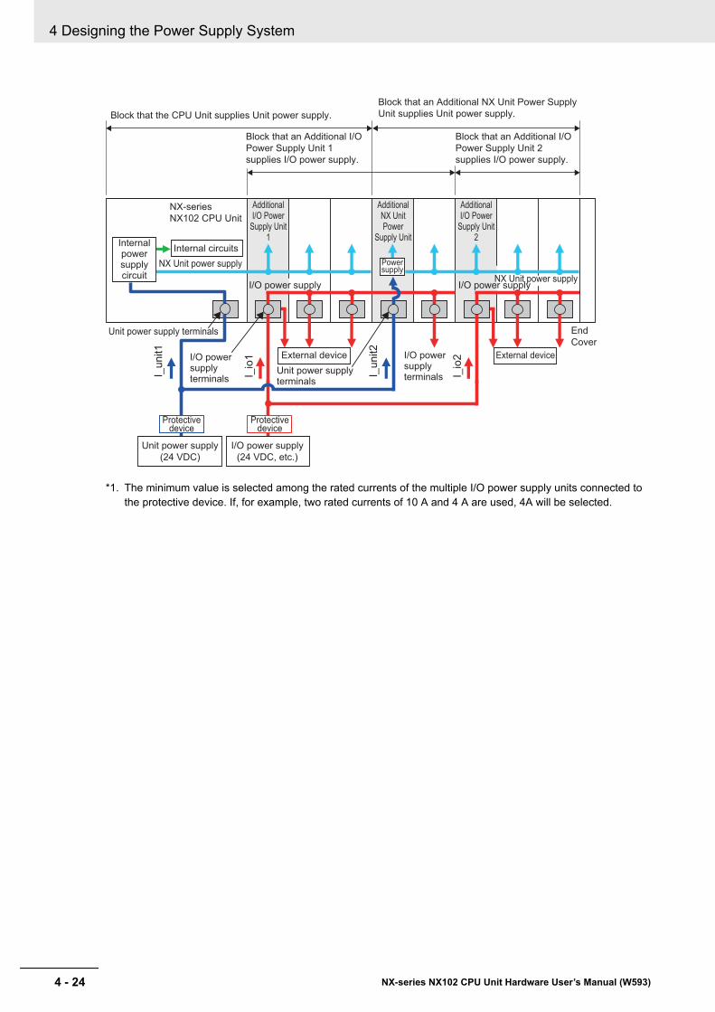
External device
End
Cover
Internal circuits
NX Unit power supply
Unit power supply terminals
Internal power supply circuit
NX-series
NX102 CPU Unit
I_u
nit1
I_u
nit2
I_io
1
I_io
2
I/O power supplyI/O power supply
Block that the CPU Unit supplies Unit power supply.
Block that an Additional I/O
Power Supply Unit 1
supplies I/O power supply.
Block that an Additional I/O
Power Supply Unit 2
supplies I/O power supply.
Block that an Additional NX Unit Power Supply
Unit supplies Unit power supply.
External device
Additional I/O Power
Supply Unit 1
Additional I/O Power
Supply Unit 2
Additional NX Unit Power
Supply Unit
NX Unit power supply
Unit power supply terminals
I/O power supply terminals
I/O power supply terminals
Power supply
Protective device
Protective device
Unit power supply
(24 VDC)
I/O power supply
(24 VDC, etc.)
*1. The minimum value is selected among the rated currents of the multiple I/O power supply units connected tothe protective device. If, for example, two rated currents of 10 A and 4 A are used, 4A will be selected.
4 Designing the Power Supply System
4 - 24 NX-series NX102 CPU Unit Hardware User’s Manual (W593)
5Installation and Wiring
This section describes how to install and wire the NX-series NX102 CPU Unit as wellas details on installation locations.
5-1 Processing at Power ON and Power OFF .................................................. 5 - 25-1-1 Power ON Operation .................................................................................... 5 - 25-1-2 Power OFF Operation................................................................................... 5 - 45-1-3 Resetting the Controller from the Sysmac Studio......................................... 5 - 6
5-2 Fail-safe Circuits .......................................................................................... 5 - 75-3 Mounting Units ............................................................................................. 5 - 9
5-3-1 Installation in a Control Panel ..................................................................... 5 - 105-3-2 Preparations for Installation ........................................................................ 5 - 145-3-3 Installing the CPU Unit................................................................................ 5 - 165-3-4 Installing and Connecting NX Units ............................................................ 5 - 185-3-5 Mounting the End Cover ............................................................................. 5 - 225-3-6 Mounting the End Plates............................................................................. 5 - 235-3-7 Attaching Markers....................................................................................... 5 - 255-3-8 Installing and Removing the SD Memory Card........................................... 5 - 265-3-9 Battery Installation ...................................................................................... 5 - 305-3-10 Removing CPU Unit.................................................................................... 5 - 335-3-11 Removing NX Units .................................................................................... 5 - 345-3-12 Assembled Appearance and Dimensions................................................... 5 - 35
5-4 Wiring .......................................................................................................... 5 - 385-4-1 Wiring the Unit Power Supply ..................................................................... 5 - 395-4-2 Wiring the Additional NX Unit Power Supply Unit ....................................... 5 - 395-4-3 Wiring the Additional I/O Power Supply Unit .............................................. 5 - 395-4-4 Wiring the Protective Devices..................................................................... 5 - 405-4-5 Grounding ................................................................................................... 5 - 415-4-6 Wiring the Built-in EtherCAT Port................................................................ 5 - 465-4-7 Wiring the Built-in EtherNet/IP Port ............................................................ 5 - 465-4-8 Wiring to the CPU Unit Terminal Block ....................................................... 5 - 46
5-5 Control Panel Installation.......................................................................... 5 - 625-5-1 Temperature................................................................................................ 5 - 625-5-2 Humidity...................................................................................................... 5 - 645-5-3 Vibration and Shock.................................................................................... 5 - 645-5-4 Atmosphere ................................................................................................ 5 - 645-5-5 Electrical Environment ................................................................................ 5 - 655-5-6 Grounding ................................................................................................... 5 - 69
5 - 1NX-series NX102 CPU Unit Hardware User’s Manual (W593)
5
5-1 Processing at Power ON and PowerOFF
WARNING• Do not touch the terminal section while power is ON. Electrical shock
may occur.• Do not disassemble any of the Units. Particularly the Units contain
parts with high voltages when power is ON or immediately after pow-er is turned OFF. Electrical shock may occur. There are also sharp in-ternal parts that may cause injury.
5-1-1 Power ON Operation
Precautions for Safe Use
It takes approximately 20 seconds to enter RUN mode after the power supply is turned ON.During that time, digital outputs on the CPU Rack will be OFF. Note that the slave outputs willbehave according to the setting value.Use the system-defined variables and the NX Unit device variables in the user program to con-firm that I/O data communications are established before attempting control operations. Exter-nal communications are also not performed during startup.
Operation Until Operation Ready StatusOnce the Unit power supply to the Unit power supply terminal starts, approximately 20 seconds elap-ses before the CPU Unit enters the operation-ready status. This period is called the startup status.The startup time depends on the slave/NX Unit configuration*1, user program, SD Memory Card us-age, SD Memory Card self-diagnosis usage*2, etc.While the CPU Unit is in the startup status, the RUN indicator flashes at a one second interval.*1. Some EtherCAT slaves can set a maximum standby time of 1 to 200 seconds. For the CPU Unit, however, the
operation-ready status exists as soon as the EtherCAT Master Function Module is functioning, regardless ofthe standby time of the EtherCAT slaves. For the EtherCAT Master Function Module, slaves that do not startwithin the maximum waiting time are treated as having an error.
*2. This function performs self-diagnosis on the inserted SD Memory Card. This is executed if the self-diagnosisat startup is enabled in the Operation Settings under Configurations and Setup − Controller Setup in theSysmac Studio.
The following processing is performed during the startup status of CPU Unit.
Process DescriptionSelf diagnosis at startup Operation is monitored for the following errors: Power Supply Er-
ror, CPU Unit Reset, Hardware Initialization Error, and System In-itialization Error. *1
Data check The _RetainFail (Retention Failure Flag) system-defined variablechanges to TRUE when the values of variables for which the Re-tain attribute was set to retain the values were not retained aftera power interruption.
5 Installation and Wiring
5 - 2 NX-series NX102 CPU Unit Hardware User’s Manual (W593)
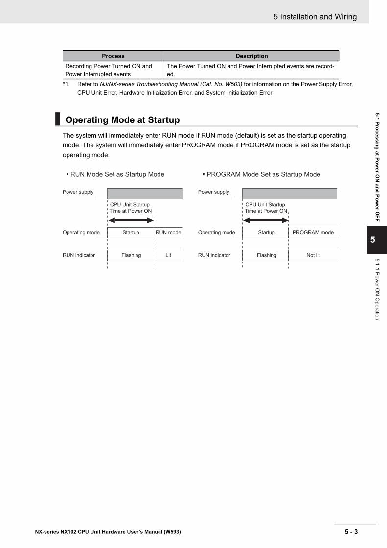
Process DescriptionRecording Power Turned ON andPower Interrupted events
The Power Turned ON and Power Interrupted events are record-ed.
*1. Refer to NJ/NX-series Troubleshooting Manual (Cat. No. W503) for information on the Power Supply Error,CPU Unit Error, Hardware Initialization Error, and System Initialization Error.
Operating Mode at StartupThe system will immediately enter RUN mode if RUN mode (default) is set as the startup operatingmode. The system will immediately enter PROGRAM mode if PROGRAM mode is set as the startupoperating mode.
• RUN Mode Set as Startup Mode • PROGRAM Mode Set as Startup Mode
CPU Unit Startup
Time at Power ON
CPU Unit Startup
Time at Power ON
Operating mode
Power supply
RUN mode
RUN indicator
Operating mode
Power supply
RUN indicatorFlashing Lit
Startup PROGRAM mode
Flashing Not lit
Startup
5 Installation and Wiring
5 - 3NX-series NX102 CPU Unit Hardware User’s Manual (W593)
5-1 Processing at Power O
N and Pow
er OFF
5
5-1-1 Power O
N O
peration
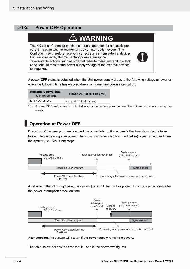
5-1-2 Power OFF Operation
WARNINGThe NX-series Controller continues normal operation for a specific peri-od of time even when a momentary power interruption occurs. TheController may therefore receive incorrect signals from external devicesthat are affected by the momentary power interruption.Take suitable actions, such as external fail-safe measures and interlockconditions, to monitor the power supply voltage of the external devicesas required.
A power OFF status is detected when the Unit power supply drops to the following voltage or lower orwhen the following time has elapsed due to a momentary power interruption.
Momentary power inter-ruption voltage Power OFF detection time
20.4 VDC or less 2 ms min.*1 to 8 ms max.*1. A power OFF status may be detected when a momentary power interruption of 2 ms or less occurs consec-
utively.
Operation at Power OFFExecution of the user program is ended if a power interruption exceeds the time shown in the tablebelow. The processing after power interruption confirmation (described below) is performed, and thenthe system (i.e., CPU Unit) stops.
System reset
Voltage drop
Executing user program
Processing after power interruption is confirmed.
DC: 20.4 V max.
Power interruption confirmed. System stops.
(CPU Unit stops.)
Power OFF detection time 2 to 8 ms
As shown in the following figure, the system (i.e. CPU Unit) will stop even if the voltage recovers afterthe power interruption detection time.
Voltage drop
DC: 20.4 V max.
Power
interruption
confirmed.
System stops.
(CPU Unit stops.)Voltage
recovery
System reset Executing user program
Power OFF detection time2 to 8 ms
Processing after power interruption is confirmed.
After stopping, the system will restart if the power supply remains recovery.
The table below defines the time that is used in the above two figures.
5 Installation and Wiring
5 - 4 NX-series NX102 CPU Unit Hardware User’s Manual (W593)
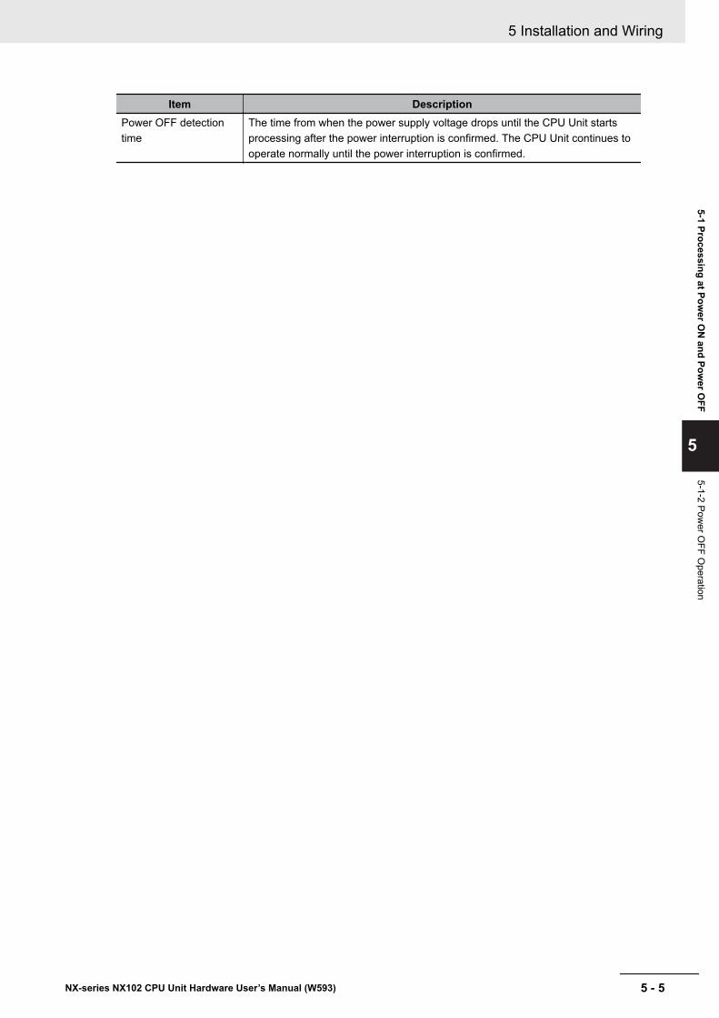
Item DescriptionPower OFF detectiontime
The time from when the power supply voltage drops until the CPU Unit startsprocessing after the power interruption is confirmed. The CPU Unit continues tooperate normally until the power interruption is confirmed.
5 Installation and Wiring
5 - 5NX-series NX102 CPU Unit Hardware User’s Manual (W593)
5-1 Processing at Power O
N and Pow
er OFF
5
5-1-2 Power O
FF Operation
Momentary Power Interruption with Continued OperationExecution of the user program will continue if a momentary power interruption is less than the follow-ing times.
The CPU Unit will not interrupt
execution of user program
Momentary power interruption time
from voltage drop until recovery
Voltage drop
Executing user program
DC: 20.4 V max.
Power OFF detection time2 to 8 ms
Voltage recovery
Processing after Power Interruption Is ConfirmedAfter a power interruption is confirmed, the CPU Unit performs the following processing and thenstops.
Item DescriptionI/O refresh I/O refresh stops, and all outputs are turned OFF. Tag data links
via the EtherNet/IP stop.Processing SD Memory Card access in
progressAny writing is interrupted, files are closed, and the Card is un-mounted.
Transferring user program(including online editing)
Interrupted.As a result, an error will occur the next time that the power isturned ON. The Controller will not operate.
User program execution User program execution is aborted even during execution of an in-struction.
Saving event log The time that a power interruption occurs and the cause (primarypower interruption) of the interruption are recorded.
5-1-3 Resetting the Controller from the Sysmac StudioYou can reset the CPU Unit from the Sysmac Studio.A reset from the Sysmac Studio follows the same operation as cycling the power supply of the Unitpower.Resetting is possible, however, only when the CPU Unit is in PROGRAM mode.Confirm the following status before the CPU Unit Reset.• Check the status of output loads.• Make sure that SD Memory Card access is not in progress.
5 Installation and Wiring
5 - 6 NX-series NX102 CPU Unit Hardware User’s Manual (W593)
5-2 Fail-safe Circuits
WARNINGProvide safety measures in external circuits to ensure safety in the sys-tem if an abnormality occurs due to malfunction of the CPU Unit,slaves, or Units or due to other external factors affecting operation. Notdoing so may result in serious accidents due to incorrect operation.• Emergency stop circuits, interlock circuits, limit circuits, and similar
safety measures must be provided in external control circuits.• The outputs may remain ON or OFF due to deposition or burning of
the output relays or destruction of the output transistors. As a coun-termeasure for such problems, external safety measures must beprovided to ensure safe operation of the system.
WARNINGThe CPU Unit will turn OFF digital outputs on the CPU Rack in the fol-lowing cases.• While the CPU Unit is on standby until RUN mode is entered after
the power is turned ON• If an error occurs in the power supply• If a system initialization error occursDigital outputs on the CPU Rack will produce outputs according to thesettings in the following cases.• If a CPU Unit error or CPU Unit reset occurs• If a major fault level Controller error occursExternal safety measures must be provided to ensure safe operation ofthe system in such cases.
WARNING• If a communications interference occurs for remote I/O or if a major
fault level error occurs, output status will be determined by the speci-fications of the external output device.Confirm the operating specifications for communications errors andmajor fault level errors and implement suitable safety measures.Correctly set all of the settings in the slaves and Units.
• If external power supplies for Units, slaves or other devices are over-loaded or short-circuited, the voltage will drop, outputs will turn OFF,and the system may be unable to read inputs. Provide external safetymeasures in controls with monitoring of external power supply volt-age as required so that the system operates safely in such a case.
• Unintended outputs may be performed when an error occurs in varia-ble memory. As a countermeasure for such problems, external safetymeasures must be provided to ensure safe operation of the system.
• Provide measures in the communications system and user programto ensure safety in the overall system even if errors or malfunctionsoccur in data link communications or remote I/O communications.
• You must implement fail-safe circuits to provide sufficient protectionin the event that abnormal signals occur as the result of broken sig-nal lines or momentary power interruptions.Not doing so may result in serious accidents due to incorrect opera-tion.
5 Installation and Wiring
5 - 7NX-series NX102 CPU Unit Hardware User’s Manual (W593)
5-2 Fail-safe Circuits
5
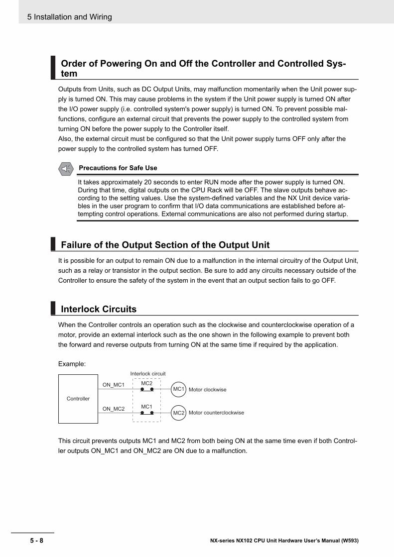
Order of Powering On and Off the Controller and Controlled Sys-tem
Outputs from Units, such as DC Output Units, may malfunction momentarily when the Unit power sup-ply is turned ON. This may cause problems in the system if the Unit power supply is turned ON afterthe I/O power supply (i.e. controlled system's power supply) is turned ON. To prevent possible mal-functions, configure an external circuit that prevents the power supply to the controlled system fromturning ON before the power supply to the Controller itself.Also, the external circuit must be configured so that the Unit power supply turns OFF only after thepower supply to the controlled system has turned OFF.
Precautions for Safe Use
It takes approximately 20 seconds to enter RUN mode after the power supply is turned ON.During that time, digital outputs on the CPU Rack will be OFF. The slave outputs behave ac-cording to the setting values. Use the system-defined variables and the NX Unit device varia-bles in the user program to confirm that I/O data communications are established before at-tempting control operations. External communications are also not performed during startup.
Failure of the Output Section of the Output UnitIt is possible for an output to remain ON due to a malfunction in the internal circuitry of the Output Unit,such as a relay or transistor in the output section. Be sure to add any circuits necessary outside of theController to ensure the safety of the system in the event that an output section fails to go OFF.
Interlock CircuitsWhen the Controller controls an operation such as the clockwise and counterclockwise operation of amotor, provide an external interlock such as the one shown in the following example to prevent boththe forward and reverse outputs from turning ON at the same time if required by the application.
Example:
Controller
Interlock circuit
Motor counterclockwise
Motor clockwise
MC2ON_MC1
MC1ON_MC2
MC1
MC2
This circuit prevents outputs MC1 and MC2 from both being ON at the same time even if both Control-ler outputs ON_MC1 and ON_MC2 are ON due to a malfunction.
5 Installation and Wiring
5 - 8 NX-series NX102 CPU Unit Hardware User’s Manual (W593)
5-3 Mounting UnitsThis section describes how to mount Units to the NX-series Controller.
Precautions for Safe Use
Always turn OFF the power supply to the Controller before you attempt any of the following.• Mounting or removing NX Units or CPU Unit• Assembling the Units• Setting DIP switches or rotary switches• Connecting cables or wiring the system• Connecting or disconnecting the terminal blocks or connectorsThe built-in power supply of the CPU Unit may continue to supply power after the power supplyis turned OFF. The POWER indicator remains lit as long as power is supplied. Make sure thatthe POWER indicator is not lit before you perform any of the above operations.
Precautions for Correct Use
• Follow the instructions in this manual to correctly perform installation.• Do not operate or store the Units in the following locations. Doing so may result in burning, in
operation stopping, or in malfunction.• Locations subject to direct sunlight• Locations subject to temperatures or humidity outside the range specified in the specifica-
tions• Locations subject to condensation as the result of severe changes in temperature• Locations subject to corrosive or flammable gases• Locations subject to dust (especially iron dust) or salts• Locations subject to exposure to water, oil, or chemicals• Locations subject to shock or vibration
• Take appropriate and sufficient countermeasures during installation in the following locations.• Locations subject to strong, high-frequency noise• Locations subject to static electricity or other forms of noise• Locations subject to strong electromagnetic fields• Locations subject to possible exposure to radioactivity• Locations close to power lines
5 Installation and Wiring
5 - 9NX-series NX102 CPU Unit Hardware User’s Manual (W593)
5-3 Mounting U
nits
5
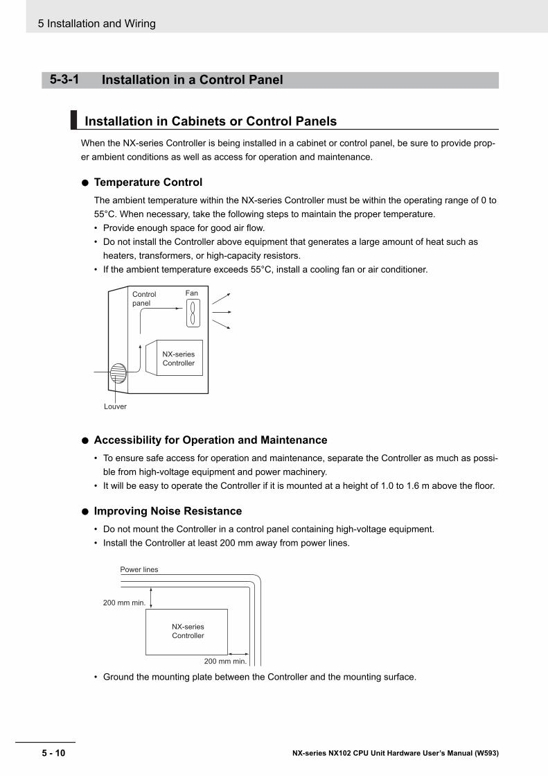
5-3-1 Installation in a Control Panel
Installation in Cabinets or Control PanelsWhen the NX-series Controller is being installed in a cabinet or control panel, be sure to provide prop-er ambient conditions as well as access for operation and maintenance.
l Temperature ControlThe ambient temperature within the NX-series Controller must be within the operating range of 0 to55°C. When necessary, take the following steps to maintain the proper temperature.• Provide enough space for good air flow.• Do not install the Controller above equipment that generates a large amount of heat such as
heaters, transformers, or high-capacity resistors.• If the ambient temperature exceeds 55°C, install a cooling fan or air conditioner.
NX-series
Controller
FanControl
panel
Louver
l Accessibility for Operation and Maintenance• To ensure safe access for operation and maintenance, separate the Controller as much as possi-
ble from high-voltage equipment and power machinery.• It will be easy to operate the Controller if it is mounted at a height of 1.0 to 1.6 m above the floor.
l Improving Noise Resistance• Do not mount the Controller in a control panel containing high-voltage equipment.• Install the Controller at least 200 mm away from power lines.
NX-series
Controller
200 mm min.
200 mm min.
Power lines
• Ground the mounting plate between the Controller and the mounting surface.
5 Installation and Wiring
5 - 10 NX-series NX102 CPU Unit Hardware User’s Manual (W593)
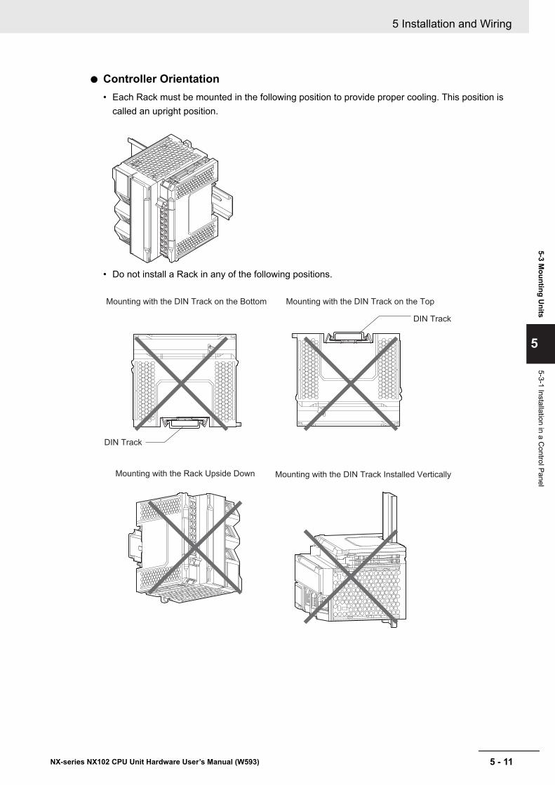
l Controller Orientation• Each Rack must be mounted in the following position to provide proper cooling. This position is
called an upright position.
• Do not install a Rack in any of the following positions.
Mounting with the DIN Track on the Bottom
Mounting with the Rack Upside Down Mounting with the DIN Track Installed Vertically
Mounting with the DIN Track on the Top
DIN Track
DIN Track
5 Installation and Wiring
5 - 11NX-series NX102 CPU Unit Hardware User’s Manual (W593)
5-3 Mounting U
nits
5
5-3-1 Installation in a Control Panel
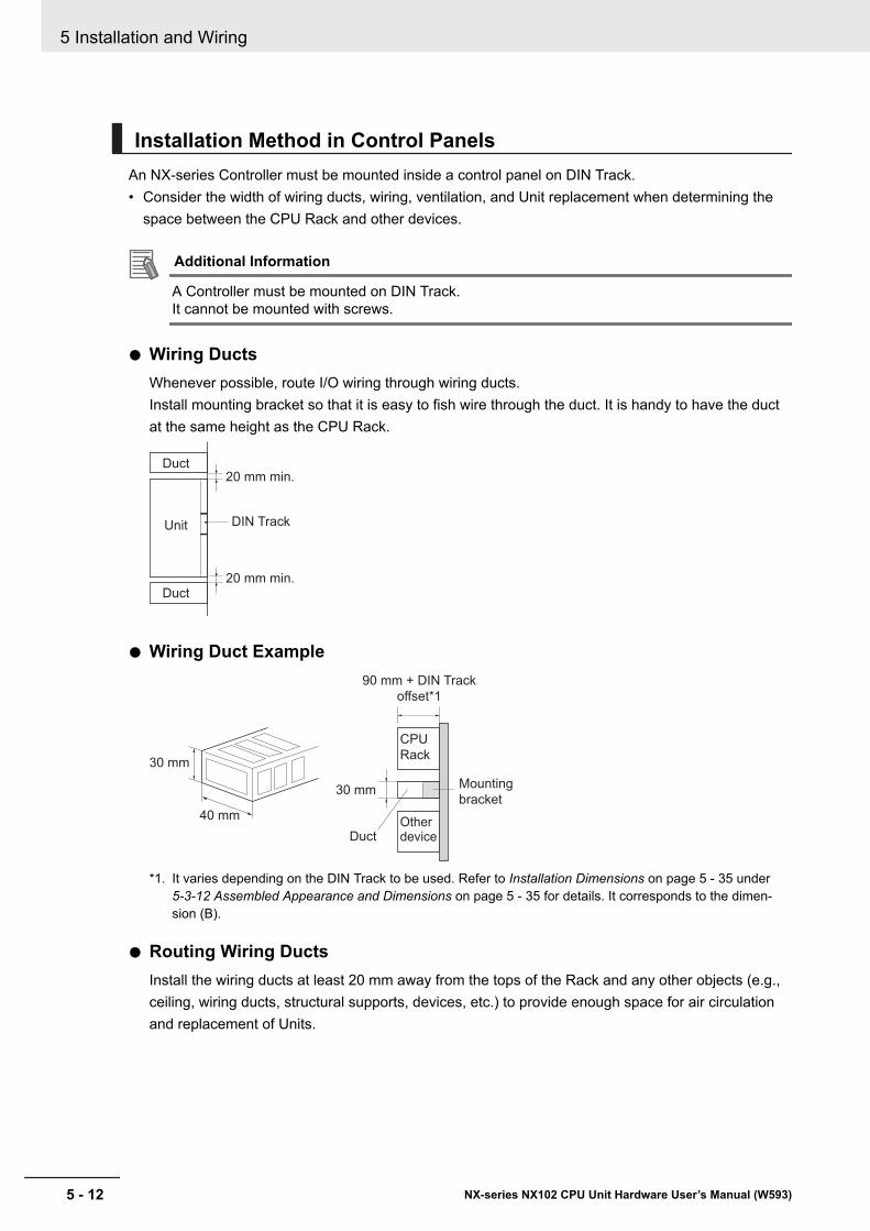
Installation Method in Control PanelsAn NX-series Controller must be mounted inside a control panel on DIN Track.• Consider the width of wiring ducts, wiring, ventilation, and Unit replacement when determining the
space between the CPU Rack and other devices.
Additional Information
A Controller must be mounted on DIN Track.It cannot be mounted with screws.
l Wiring DuctsWhenever possible, route I/O wiring through wiring ducts.Install mounting bracket so that it is easy to fish wire through the duct. It is handy to have the ductat the same height as the CPU Rack.
Duct
Duct
Unit
20 mm min.
20 mm min.
DIN Track
l Wiring Duct Example
40 mm
30 mm
30 mm
CPU
Rack
Other device
90 mm + DIN Track
offset*1
Duct
Mounting
bracket
*1. It varies depending on the DIN Track to be used. Refer to Installation Dimensions on page 5 - 35 under 5-3-12 Assembled Appearance and Dimensions on page 5 - 35 for details. It corresponds to the dimen-sion (B).
l Routing Wiring DuctsInstall the wiring ducts at least 20 mm away from the tops of the Rack and any other objects (e.g.,ceiling, wiring ducts, structural supports, devices, etc.) to provide enough space for air circulationand replacement of Units.
5 Installation and Wiring
5 - 12 NX-series NX102 CPU Unit Hardware User’s Manual (W593)
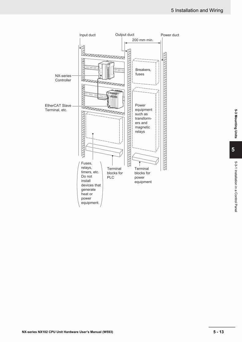
Input duct Power ductOutput duct
Breakers,
fuses
EtherCAT Slave
Terminal, etc.
200 mm min.
Power
equipment
such as
transform-
ers and
magnetic
relays
Terminal
blocks for
power
equipment
Terminal
blocks for
PLC
Fuses,
relays,
timers, etc.
Do not
install
devices that
generate
heat or
power
equipment.
NX-series
Controller
5 Installation and Wiring
5 - 13NX-series NX102 CPU Unit Hardware User’s Manual (W593)
5-3 Mounting U
nits
5
5-3-1 Installation in a Control Panel

5-3-2 Preparations for InstallationWe recommend using the following products to install the Unit on a DIN Track.
Name Model Manufacturer Remarks35-mm DIN Track PFP-50N OMRON Corporation • Length: 50 cm
• Material: Aluminum• Surface treatment: Insulated
PFP-100N OMRON Corporation • Length: 100 cm• Material: Aluminum• Surface treatment: Insulated
NS 35/ 7,5 PERF Phoenix Contact • Length: 75.5, 95.5, 115.5, or 200 cm• Material: Steel• Surface treatment: Conductive
NS 35/ 15 PERF Phoenix Contact • Length: 75.5, 95.5, 115.5, or 200 cm• Material: Steel• Surface treatment: Conductive
End Plate PFP-M OMRON Corporation Two End Plates are required for eachCPU Rack.
CLIPFIX 35 Phoenix Contact Two End Plates are required for eachCPU Rack.
Not all of the combinations of the DIN Tracks and End Plates listed above are possible.Confirm applicability of the combinations in the following table.
DIN Track modelPFP-M
(OMRON)CLIPFIX 35
(Phoenix Contact)PFP-50N Possible PossiblePFP-100N Possible PossibleNS 35/ 7,5 PERF Possible PossibleNS 35/ 15 PERF Not possible Possible
Also, use screws and washers of the following sizes to fix the DIN Tracks.
(a): Dimensions from the screw head to the fastening surface
(a)
DIN Track modelApplicablescrew size
(a)
PFP-50N M4 4.1 mm max.NS 35/ 7,5 PERF M6 4.6 mm max.NS 35/ 15 PERF M6 10 mm max.
If you use any DIN Track other than those listed in the table above, refer to the dimensions shown in 5-3-12 Assembled Appearance and Dimensions on page 5 - 35 and use proper screws and washers.
l DIN TracksPFP-100N/50N DIN Track
5 Installation and Wiring
5 - 14 NX-series NX102 CPU Unit Hardware User’s Manual (W593)
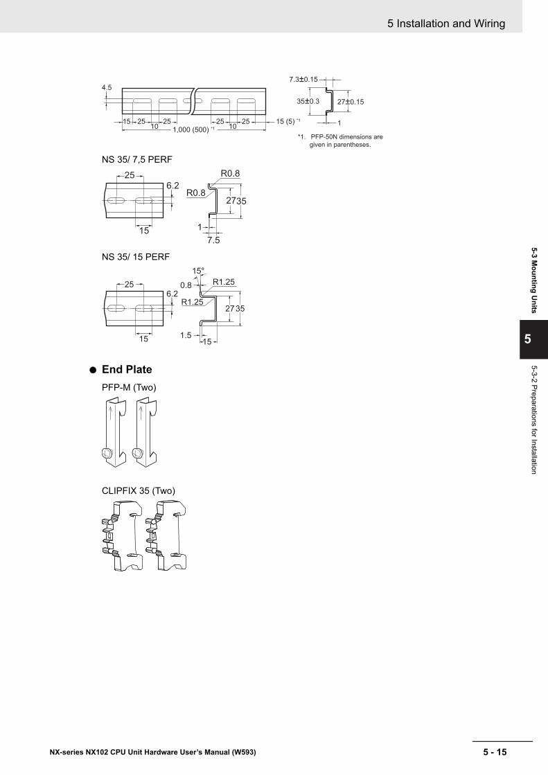
1,000 (500) *1
1510
4.5
25 25 2510
25 15 (5) *11
7.3±0.15
35±0.3 27±0.15
*1. PFP-50N dimensions are
given in parentheses.
NS 35/ 7,5 PERF
1
7.5
3527
R0.8
R0.86.2
15
25
NS 35/ 15 PERF
1.5
0.8
15
3527
R1.25
15°
R1.256.2
15
25
l End PlatePFP-M (Two)
CLIPFIX 35 (Two)
5 Installation and Wiring
5 - 15NX-series NX102 CPU Unit Hardware User’s Manual (W593)
5-3 Mounting U
nits
5
5-3-2 Preparations for Installation
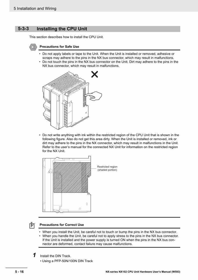
5-3-3 Installing the CPU UnitThis section describes how to install the CPU Unit.
Precautions for Safe Use
• Do not apply labels or tape to the Unit. When the Unit is installed or removed, adhesive orscraps may adhere to the pins in the NX bus connector, which may result in malfunctions.
• Do not touch the pins in the NX bus connector on the Unit. Dirt may adhere to the pins in theNX bus connector, which may result in malfunctions.
• Do not write anything with ink within the restricted region of the CPU Unit that is shown in thefollowing figure. Also do not get this area dirty. When the Unit is installed or removed, ink ordirt may adhere to the pins in the NX connector, which may result in malfunctions in the Unit.Refer to the user’s manual for the connected NX Unit for information on the restricted regionfor the NX Unit.
Restricted region
(shaded portion)
Precautions for Correct Use
• When you install the Unit, be careful not to touch or bump the pins in the NX bus connector.• When you handle the Unit, be careful not to apply stress to the pins in the NX bus connector.
If the Unit is installed and the power supply is turned ON when the pins in the NX bus con-nector are deformed, contact failure may cause malfunctions.
1 Install the DIN Track.• Using a PFP-50N/100N DIN Track
5 Installation and Wiring
5 - 16 NX-series NX102 CPU Unit Hardware User’s Manual (W593)
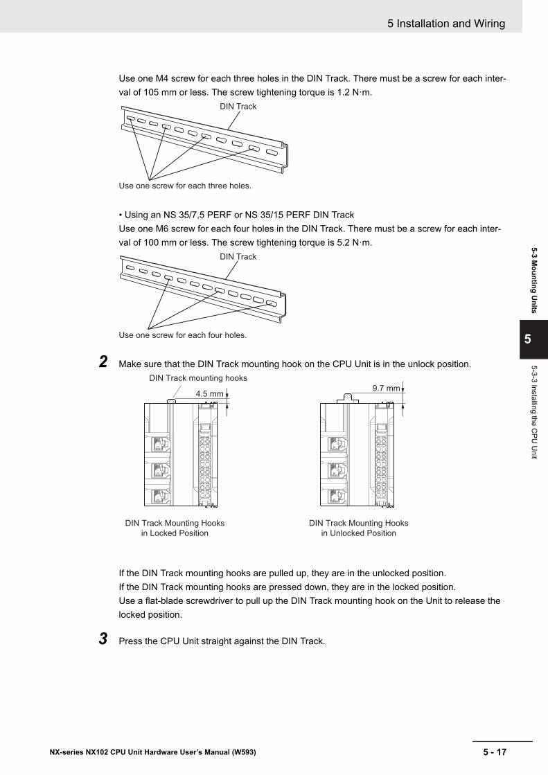
Use one M4 screw for each three holes in the DIN Track. There must be a screw for each inter-val of 105 mm or less. The screw tightening torque is 1.2 N·m.
DIN Track
Use one screw for each three holes.
• Using an NS 35/7,5 PERF or NS 35/15 PERF DIN TrackUse one M6 screw for each four holes in the DIN Track. There must be a screw for each inter-val of 100 mm or less. The screw tightening torque is 5.2 N·m.
DIN Track
Use one screw for each four holes.
2 Make sure that the DIN Track mounting hook on the CPU Unit is in the unlock position.
4.5 mm
DIN Track mounting hooks
DIN Track Mounting Hooks
in Locked Position
DIN Track Mounting Hooks
in Unlocked Position
9.7 mm
If the DIN Track mounting hooks are pulled up, they are in the unlocked position.If the DIN Track mounting hooks are pressed down, they are in the locked position.Use a flat-blade screwdriver to pull up the DIN Track mounting hook on the Unit to release thelocked position.
3 Press the CPU Unit straight against the DIN Track.
5 Installation and Wiring
5 - 17NX-series NX102 CPU Unit Hardware User’s Manual (W593)
5-3 Mounting U
nits
5
5-3-3 Installing the CPU
Unit
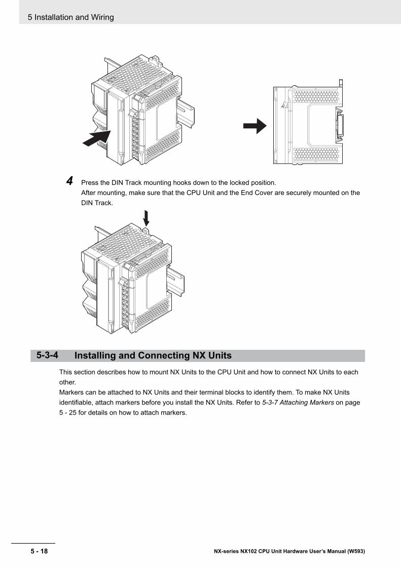
4 Press the DIN Track mounting hooks down to the locked position.After mounting, make sure that the CPU Unit and the End Cover are securely mounted on theDIN Track.
5-3-4 Installing and Connecting NX UnitsThis section describes how to mount NX Units to the CPU Unit and how to connect NX Units to eachother.Markers can be attached to NX Units and their terminal blocks to identify them. To make NX Unitsidentifiable, attach markers before you install the NX Units. Refer to 5-3-7 Attaching Markers on page5 - 25 for details on how to attach markers.
5 Installation and Wiring
5 - 18 NX-series NX102 CPU Unit Hardware User’s Manual (W593)
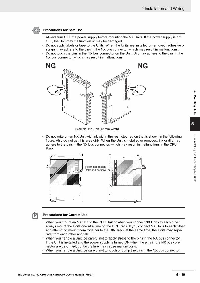
Precautions for Safe Use
• Always turn OFF the power supply before mounting the NX Units. If the power supply is notOFF, the Unit may malfunction or may be damaged.
• Do not apply labels or tape to the Units. When the Units are installed or removed, adhesive orscraps may adhere to the pins in the NX bus connector, which may result in malfunctions.
• Do not touch the pins in the NX bus connector on the Unit. Dirt may adhere to the pins in theNX bus connector, which may result in malfunctions.
Example: NX Unit (12 mm width)
NGNG
• Do not write on an NX Unit with ink within the restricted region that is shown in the followingfigure. Also do not get this area dirty. When the Unit is installed or removed, ink or dirt mayadhere to the pins in the NX bus connector, which may result in malfunctions in the CPURack.
Restricted region
(shaded portion)
Precautions for Correct Use
• When you mount an NX Unit to the CPU Unit or when you connect NX Units to each other,always mount the Units one at a time on the DIN Track. If you connect NX Units to each otherand attempt to mount them together to the DIN Track at the same time, the Units may sepa-rate from each other and fall.
• When you handle a Unit, be careful not to apply stress to the pins in the NX bus connector.If the Unit is installed and the power supply is turned ON when the pins in the NX bus con-nector are deformed, contact failure may cause malfunctions.
• When you handle a Unit, be careful not to touch or bump the pins in the NX bus connector.
5 Installation and Wiring
5 - 19NX-series NX102 CPU Unit Hardware User’s Manual (W593)
5-3 Mounting U
nits
5
5-3-4 Installing and Connecting N
X Units
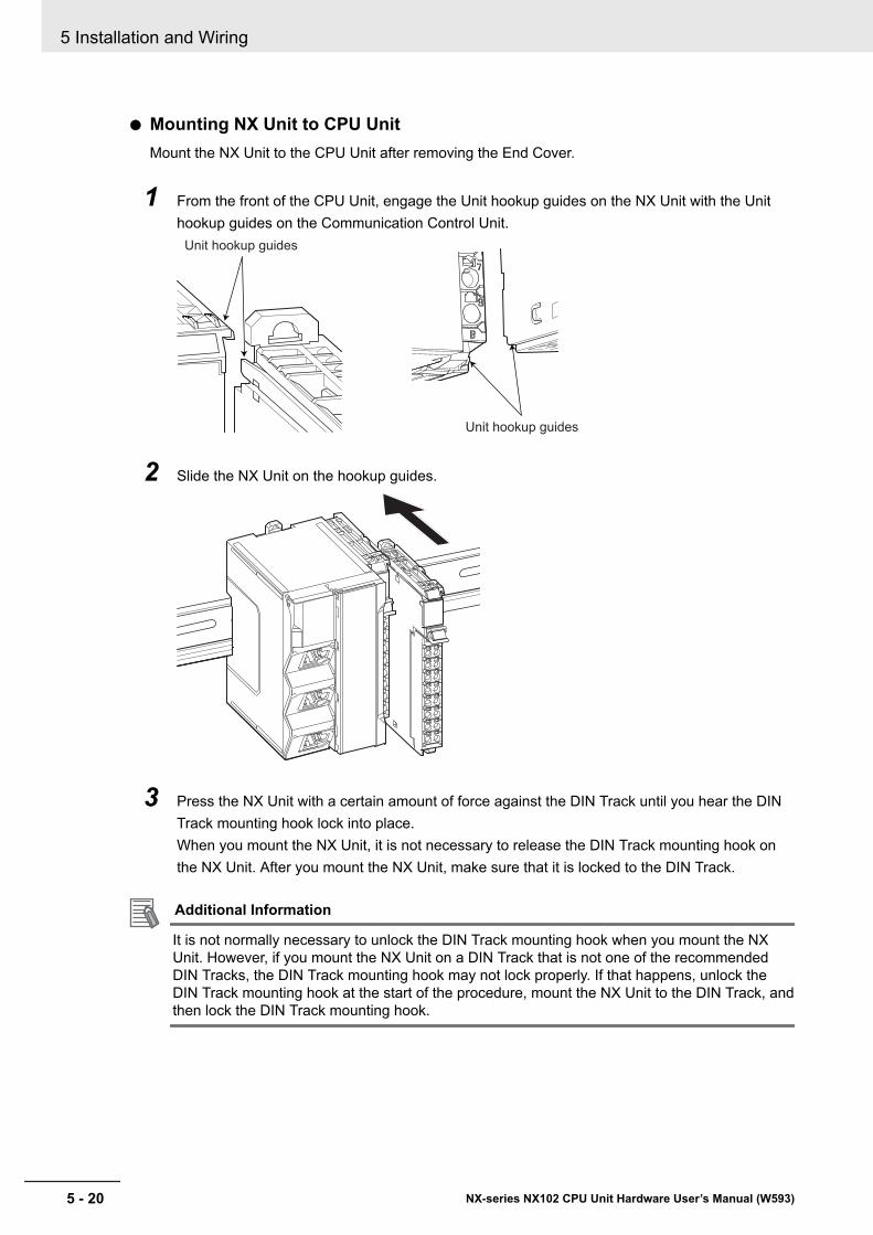
l Mounting NX Unit to CPU UnitMount the NX Unit to the CPU Unit after removing the End Cover.
1 From the front of the CPU Unit, engage the Unit hookup guides on the NX Unit with the Unithookup guides on the Communication Control Unit.
Unit hookup guides
Unit hookup guides
2 Slide the NX Unit on the hookup guides.
3 Press the NX Unit with a certain amount of force against the DIN Track until you hear the DINTrack mounting hook lock into place.When you mount the NX Unit, it is not necessary to release the DIN Track mounting hook onthe NX Unit. After you mount the NX Unit, make sure that it is locked to the DIN Track.
Additional Information
It is not normally necessary to unlock the DIN Track mounting hook when you mount the NXUnit. However, if you mount the NX Unit on a DIN Track that is not one of the recommendedDIN Tracks, the DIN Track mounting hook may not lock properly. If that happens, unlock theDIN Track mounting hook at the start of the procedure, mount the NX Unit to the DIN Track, andthen lock the DIN Track mounting hook.
5 Installation and Wiring
5 - 20 NX-series NX102 CPU Unit Hardware User’s Manual (W593)
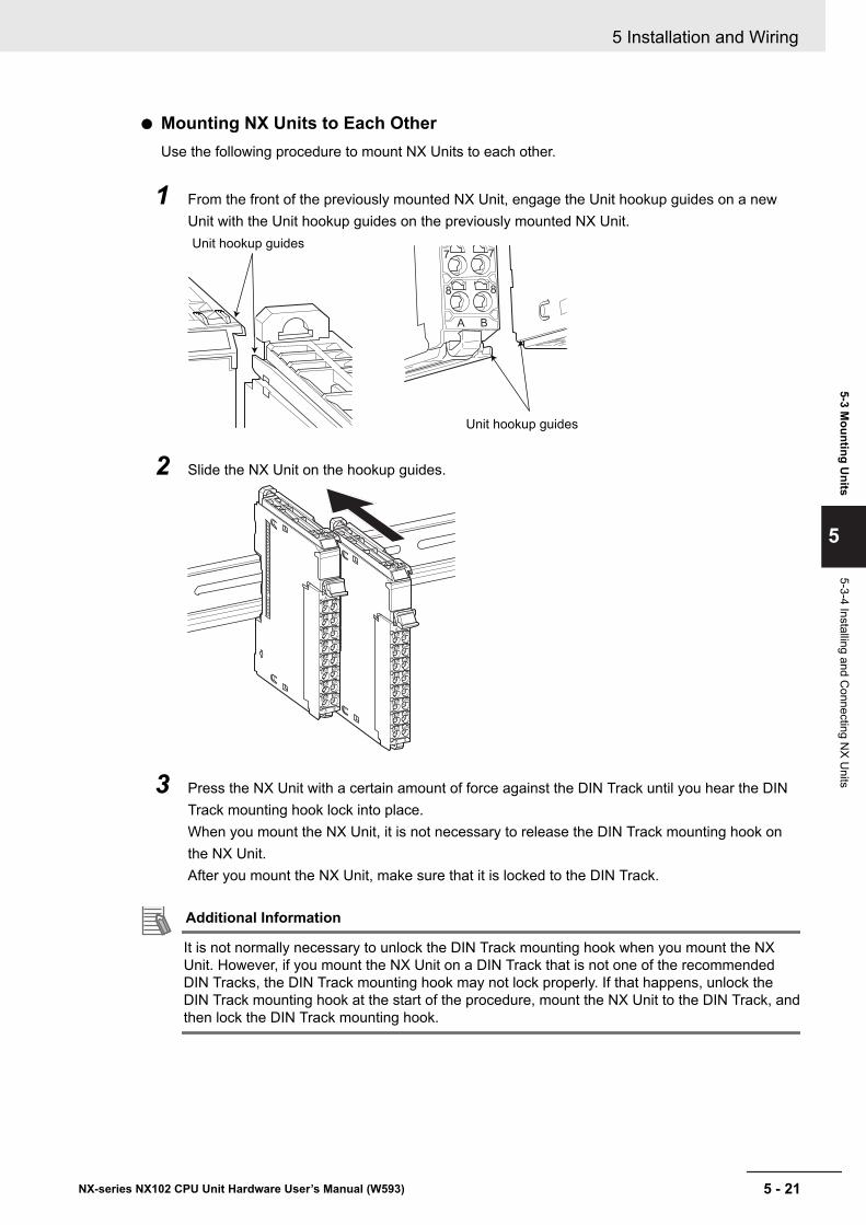
l Mounting NX Units to Each OtherUse the following procedure to mount NX Units to each other.
1 From the front of the previously mounted NX Unit, engage the Unit hookup guides on a newUnit with the Unit hookup guides on the previously mounted NX Unit.Unit hookup guides
Unit hookup guides
2 Slide the NX Unit on the hookup guides.
3 Press the NX Unit with a certain amount of force against the DIN Track until you hear the DINTrack mounting hook lock into place.When you mount the NX Unit, it is not necessary to release the DIN Track mounting hook onthe NX Unit.After you mount the NX Unit, make sure that it is locked to the DIN Track.
Additional Information
It is not normally necessary to unlock the DIN Track mounting hook when you mount the NXUnit. However, if you mount the NX Unit on a DIN Track that is not one of the recommendedDIN Tracks, the DIN Track mounting hook may not lock properly. If that happens, unlock theDIN Track mounting hook at the start of the procedure, mount the NX Unit to the DIN Track, andthen lock the DIN Track mounting hook.
5 Installation and Wiring
5 - 21NX-series NX102 CPU Unit Hardware User’s Manual (W593)
5-3 Mounting U
nits
5
5-3-4 Installing and Connecting N
X Units
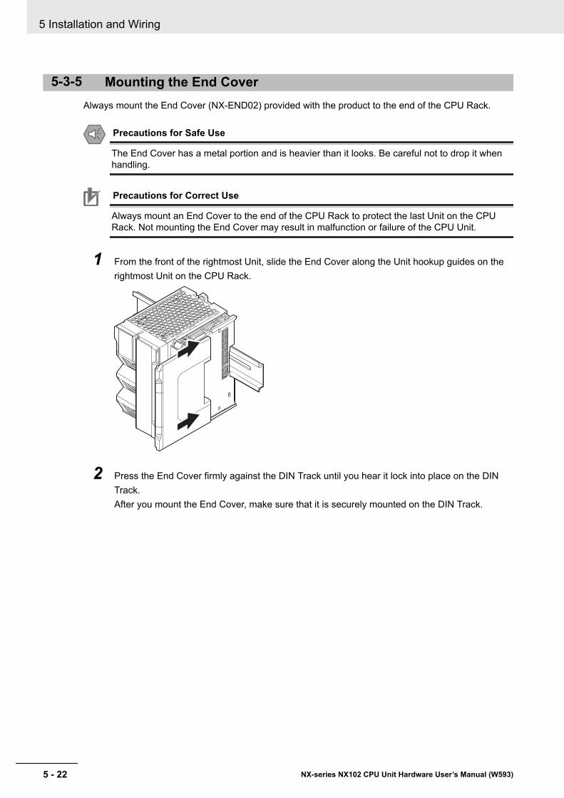
5-3-5 Mounting the End CoverAlways mount the End Cover (NX-END02) provided with the product to the end of the CPU Rack.
Precautions for Safe Use
The End Cover has a metal portion and is heavier than it looks. Be careful not to drop it whenhandling.
Precautions for Correct Use
Always mount an End Cover to the end of the CPU Rack to protect the last Unit on the CPURack. Not mounting the End Cover may result in malfunction or failure of the CPU Unit.
1 From the front of the rightmost Unit, slide the End Cover along the Unit hookup guides on therightmost Unit on the CPU Rack.
2 Press the End Cover firmly against the DIN Track until you hear it lock into place on the DINTrack.After you mount the End Cover, make sure that it is securely mounted on the DIN Track.
5 Installation and Wiring
5 - 22 NX-series NX102 CPU Unit Hardware User’s Manual (W593)
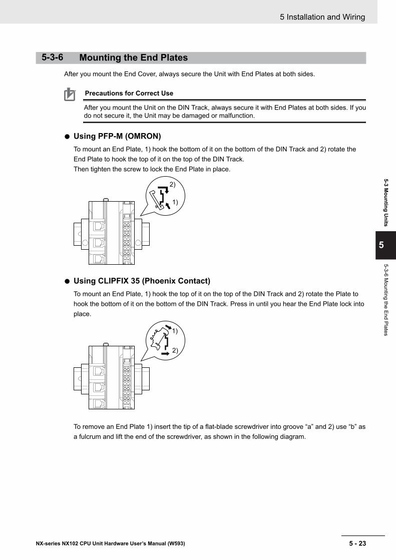
5-3-6 Mounting the End PlatesAfter you mount the End Cover, always secure the Unit with End Plates at both sides.
Precautions for Correct Use
After you mount the Unit on the DIN Track, always secure it with End Plates at both sides. If youdo not secure it, the Unit may be damaged or malfunction.
l Using PFP-M (OMRON)To mount an End Plate, 1) hook the bottom of it on the bottom of the DIN Track and 2) rotate theEnd Plate to hook the top of it on the top of the DIN Track.Then tighten the screw to lock the End Plate in place.
1)
2)
l Using CLIPFIX 35 (Phoenix Contact)To mount an End Plate, 1) hook the top of it on the top of the DIN Track and 2) rotate the Plate tohook the bottom of it on the bottom of the DIN Track. Press in until you hear the End Plate lock intoplace.
1)
2)
To remove an End Plate 1) insert the tip of a flat-blade screwdriver into groove “a” and 2) use “b” asa fulcrum and lift the end of the screwdriver, as shown in the following diagram.
5 Installation and Wiring
5 - 23NX-series NX102 CPU Unit Hardware User’s Manual (W593)
5-3 Mounting U
nits
5
5-3-6 Mounting the End Plates
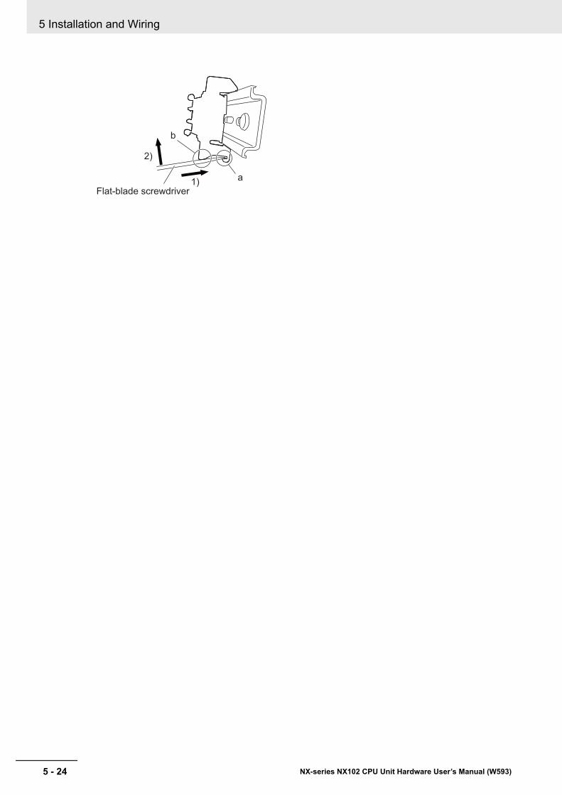
a
b
Flat-blade screwdriver
1)
2)
5 Installation and Wiring
5 - 24 NX-series NX102 CPU Unit Hardware User’s Manual (W593)
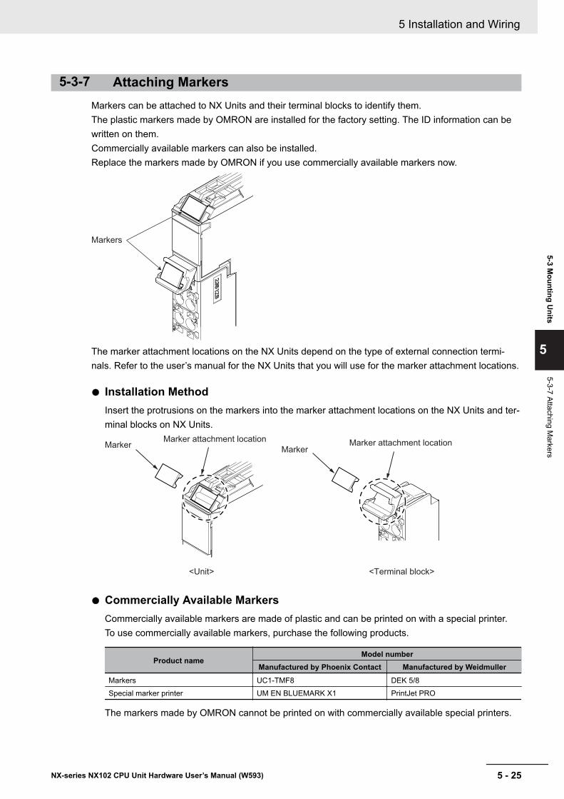
5-3-7 Attaching MarkersMarkers can be attached to NX Units and their terminal blocks to identify them.The plastic markers made by OMRON are installed for the factory setting. The ID information can bewritten on them.Commercially available markers can also be installed.Replace the markers made by OMRON if you use commercially available markers now.
Markers
The marker attachment locations on the NX Units depend on the type of external connection termi-nals. Refer to the user’s manual for the NX Units that you will use for the marker attachment locations.
l Installation MethodInsert the protrusions on the markers into the marker attachment locations on the NX Units and ter-minal blocks on NX Units.
MarkerMarker
Marker attachment locationMarker attachment location
<Terminal block><Unit>
l Commercially Available MarkersCommercially available markers are made of plastic and can be printed on with a special printer.To use commercially available markers, purchase the following products.
Product nameModel number
Manufactured by Phoenix Contact Manufactured by WeidmullerMarkers UC1-TMF8 DEK 5/8Special marker printer UM EN BLUEMARK X1 PrintJet PRO
The markers made by OMRON cannot be printed on with commercially available special printers.
5 Installation and Wiring
5 - 25NX-series NX102 CPU Unit Hardware User’s Manual (W593)
5-3 Mounting U
nits
5
5-3-7 Attaching Markers
5-3-8 Installing and Removing the SD Memory Card
Before Using an SD Memory Card• Keep the following precautions because an SD Memory Card may become unusable.
a) Do not turn OFF the power supply to the Controller while the SD BUSY indicator is lit (i.e., whileSD Memory Card access is in progress).The SD BUSY indicator is lit when the SD Memory Card is accessed from the user program orfrom a computer through FTP.
b) Do not remove the SD Memory Card while the SD BUSY indicator is lit or the SD PWR indicatoris lit (i.e., while SD Memory Card power is supplied).Press the SD Memory Card power supply switch and confirm that the SD BUSY indicator or SDPWR indicator is not lit before you remove the SD Memory Card.
• Never insert the SD Memory Card facing the wrong way.If the SD Memory Card is inserted forcibly, it may become unusable.
• To format the SD Memory Card (e.g., to delete all of the data), insert the SD Memory Card in theCPU Unit and perform the operation from the Sysmac Studio.
• The SD Memory Card uses flash memory, and so its service life is limited. When the end of the SDMemory Card’s service life approaches, the ability to write data is lost, and data is sometimes notretained after writing. The service life depends on the size of the data that is written and on the am-bient temperature. For the unlikely event that data is lost, it is recommended to periodically back updata.
• The service life may be extremely short if a non-OMRON SD Memory Card is used. Also, operationmay be affected due to deterioration in writing performance.
• If you use an OMRON SD Memory Card, the end of the life of the SD Memory Card can be detectedin the following ways.a) _Card1Deteriorated (SD Memory Card Life Warning Flag) system-defined variableb) SD Memory Card Life Exceeded event in the event log
5 Installation and Wiring
5 - 26 NX-series NX102 CPU Unit Hardware User’s Manual (W593)
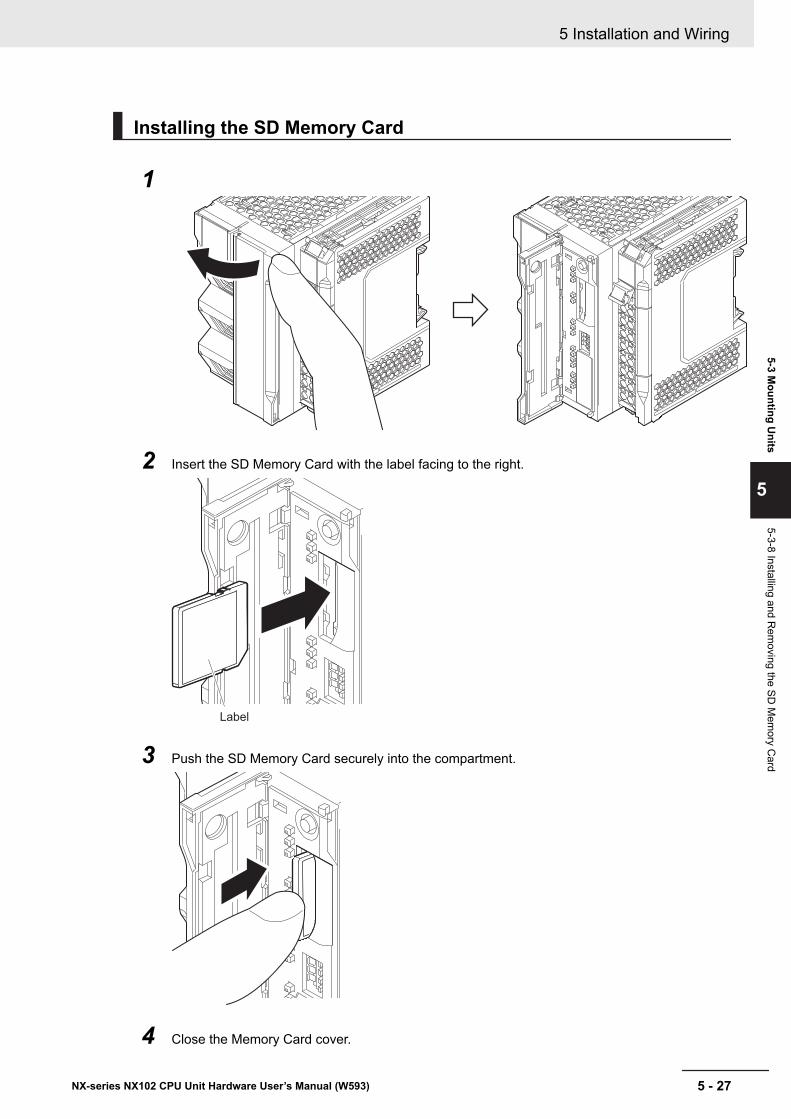
Installing the SD Memory Card
1
2 Insert the SD Memory Card with the label facing to the right.
Label
3 Push the SD Memory Card securely into the compartment.
4 Close the Memory Card cover.
5 Installation and Wiring
5 - 27NX-series NX102 CPU Unit Hardware User’s Manual (W593)
5-3 Mounting U
nits
5
5-3-8 Installing and Rem
oving the SD M
emory C
ard
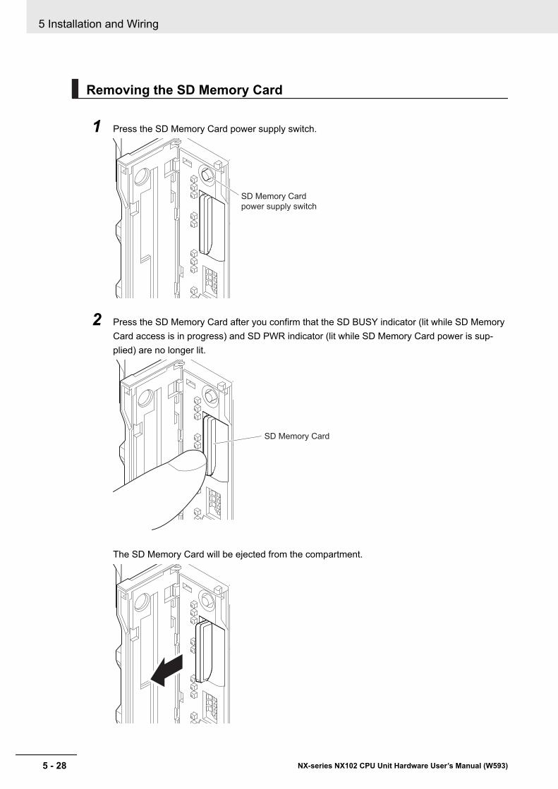
Removing the SD Memory Card
1 Press the SD Memory Card power supply switch.
SD Memory Card
power supply switch
2 Press the SD Memory Card after you confirm that the SD BUSY indicator (lit while SD MemoryCard access is in progress) and SD PWR indicator (lit while SD Memory Card power is sup-plied) are no longer lit.
SD Memory Card
The SD Memory Card will be ejected from the compartment.
5 Installation and Wiring
5 - 28 NX-series NX102 CPU Unit Hardware User’s Manual (W593)
3 Pull out the SD Memory Card.
4 Close the Memory Card cover.
5 Installation and Wiring
5 - 29NX-series NX102 CPU Unit Hardware User’s Manual (W593)
5-3 Mounting U
nits
5
5-3-8 Installing and Rem
oving the SD M
emory C
ard
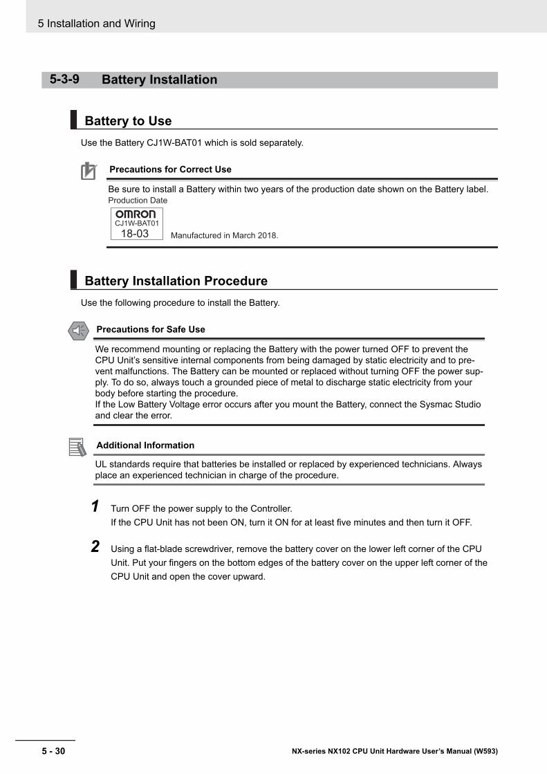
5-3-9 Battery Installation
Battery to UseUse the Battery CJ1W-BAT01 which is sold separately.
Precautions for Correct Use
Be sure to install a Battery within two years of the production date shown on the Battery label.
CJ1W-BAT01
18-03 Manufactured in March 2018.
Production Date
Battery Installation ProcedureUse the following procedure to install the Battery.
Precautions for Safe Use
We recommend mounting or replacing the Battery with the power turned OFF to prevent theCPU Unit’s sensitive internal components from being damaged by static electricity and to pre-vent malfunctions. The Battery can be mounted or replaced without turning OFF the power sup-ply. To do so, always touch a grounded piece of metal to discharge static electricity from yourbody before starting the procedure.If the Low Battery Voltage error occurs after you mount the Battery, connect the Sysmac Studioand clear the error.
Additional Information
UL standards require that batteries be installed or replaced by experienced technicians. Alwaysplace an experienced technician in charge of the procedure.
1 Turn OFF the power supply to the Controller.If the CPU Unit has not been ON, turn it ON for at least five minutes and then turn it OFF.
2 Using a flat-blade screwdriver, remove the battery cover on the lower left corner of the CPUUnit. Put your fingers on the bottom edges of the battery cover on the upper left corner of theCPU Unit and open the cover upward.
5 Installation and Wiring
5 - 30 NX-series NX102 CPU Unit Hardware User’s Manual (W593)
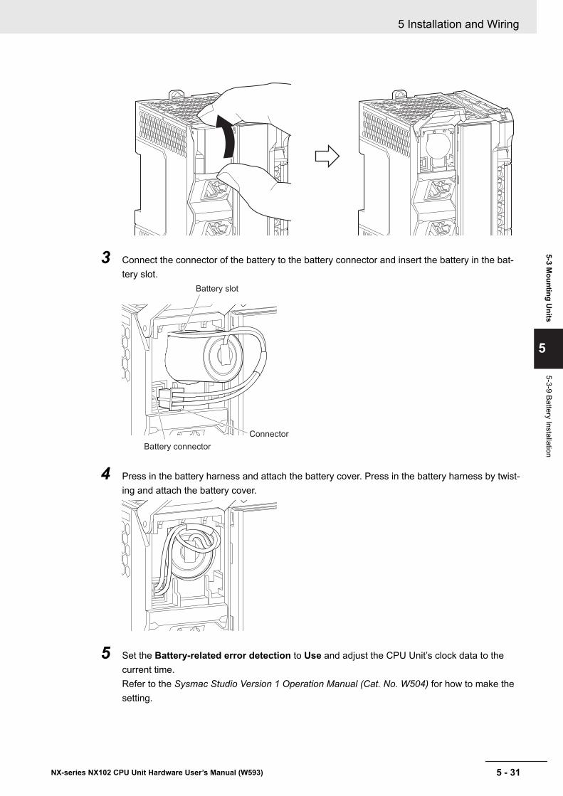
3 Connect the connector of the battery to the battery connector and insert the battery in the bat-tery slot.
Battery connector
Battery slot
Connector
4 Press in the battery harness and attach the battery cover. Press in the battery harness by twist-ing and attach the battery cover.
5 Set the Battery-related error detection to Use and adjust the CPU Unit’s clock data to thecurrent time.Refer to the Sysmac Studio Version 1 Operation Manual (Cat. No. W504) for how to make thesetting.
5 Installation and Wiring
5 - 31NX-series NX102 CPU Unit Hardware User’s Manual (W593)
5-3 Mounting U
nits
5
5-3-9 Battery Installation
Precautions for Safe Use
• Never short-circuit the battery terminals; never charge the battery; never disassemble thebattery; and never heat or incinerate the battery. Doing any of these may cause the battery toleak, heat, ignite, or rupture.
• Dispose of any battery that has been dropped on the floor or otherwise subjected to exces-sive shock. Batteries that have been subjected to shock may leak if they are used.
5 Installation and Wiring
5 - 32 NX-series NX102 CPU Unit Hardware User’s Manual (W593)
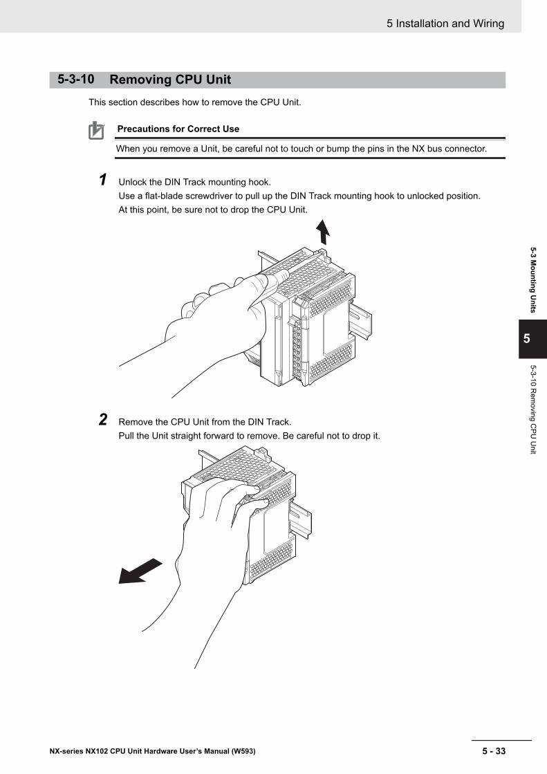
5-3-10 Removing CPU UnitThis section describes how to remove the CPU Unit.
Precautions for Correct Use
When you remove a Unit, be careful not to touch or bump the pins in the NX bus connector.
1 Unlock the DIN Track mounting hook.Use a flat-blade screwdriver to pull up the DIN Track mounting hook to unlocked position.At this point, be sure not to drop the CPU Unit.
2 Remove the CPU Unit from the DIN Track.Pull the Unit straight forward to remove. Be careful not to drop it.
5 Installation and Wiring
5 - 33NX-series NX102 CPU Unit Hardware User’s Manual (W593)
5-3 Mounting U
nits
5
5-3-10 Rem
oving CPU
Unit
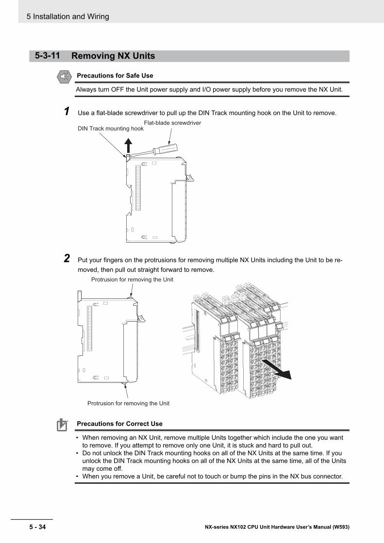
5-3-11 Removing NX Units
Precautions for Safe Use
Always turn OFF the Unit power supply and I/O power supply before you remove the NX Unit.
1 Use a flat-blade screwdriver to pull up the DIN Track mounting hook on the Unit to remove.Flat-blade screwdriver
DIN Track mounting hook
2 Put your fingers on the protrusions for removing multiple NX Units including the Unit to be re-moved, then pull out straight forward to remove.
Protrusion for removing the Unit
Protrusion for removing the Unit
Precautions for Correct Use
• When removing an NX Unit, remove multiple Units together which include the one you wantto remove. If you attempt to remove only one Unit, it is stuck and hard to pull out.
• Do not unlock the DIN Track mounting hooks on all of the NX Units at the same time. If youunlock the DIN Track mounting hooks on all of the NX Units at the same time, all of the Unitsmay come off.
• When you remove a Unit, be careful not to touch or bump the pins in the NX bus connector.
5 Installation and Wiring
5 - 34 NX-series NX102 CPU Unit Hardware User’s Manual (W593)
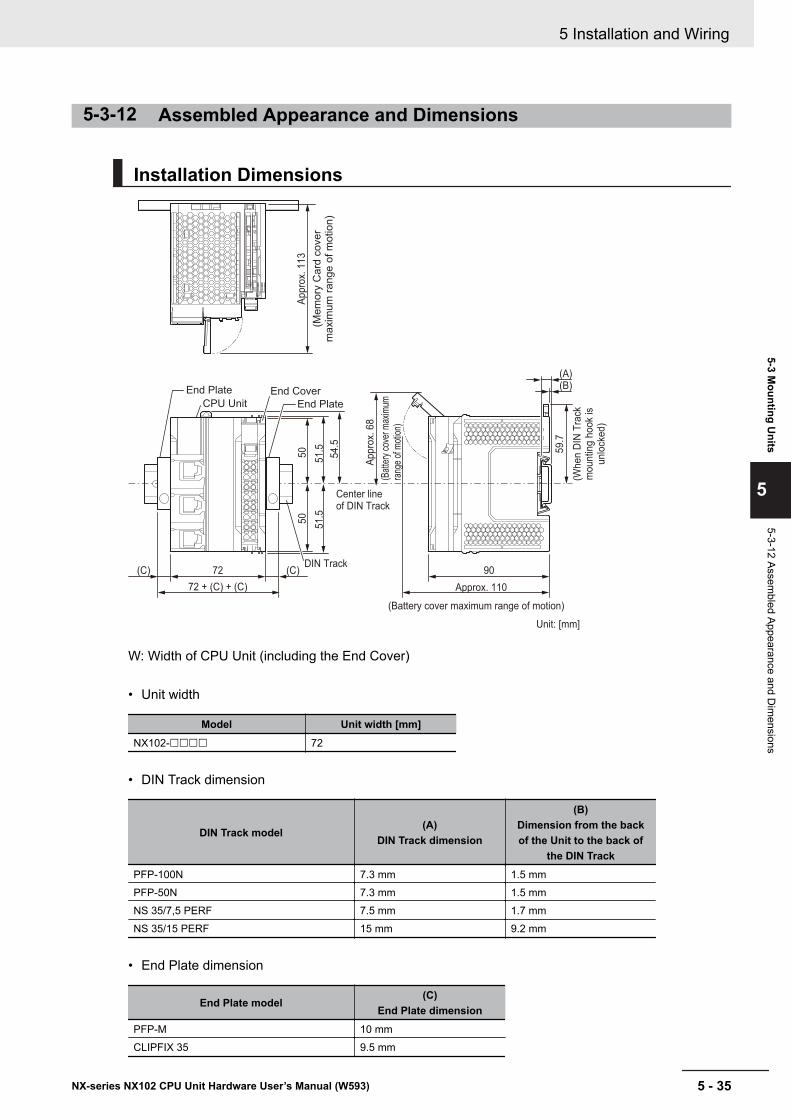
5-3-12 Assembled Appearance and Dimensions
Installation Dimensions
DIN Track
End Plate
CPU Unit
72 + (C) + (C)
72
50
51.5
50
51.5
54.5
Appro
x. 6
8
59.7
Approx. 110
(C) 90
(A)(B)
(C)
End Plate
Center line of DIN Track
(Bat
tery
cov
er m
axim
um
rang
e of
mot
ion)
Appro
x. 1
13
(Me
mo
ry C
ard
co
ve
r m
axim
um
ra
ng
e o
f m
otio
n)
(When D
IN T
rack
m
ountin
g h
ook
is
unlo
cked)
(Battery cover maximum range of motion)
Unit: [mm]
End Cover
W: Width of CPU Unit (including the End Cover)
• Unit width
Model Unit width [mm]NX102-££££ 72
• DIN Track dimension
DIN Track model(A)
DIN Track dimension
(B)Dimension from the backof the Unit to the back of
the DIN TrackPFP-100N 7.3 mm 1.5 mmPFP-50N 7.3 mm 1.5 mmNS 35/7,5 PERF 7.5 mm 1.7 mmNS 35/15 PERF 15 mm 9.2 mm
• End Plate dimension
End Plate model(C)
End Plate dimensionPFP-M 10 mmCLIPFIX 35 9.5 mm
5 Installation and Wiring
5 - 35NX-series NX102 CPU Unit Hardware User’s Manual (W593)
5-3 Mounting U
nits
5
5-3-12 Assembled Appearance and D
imensions
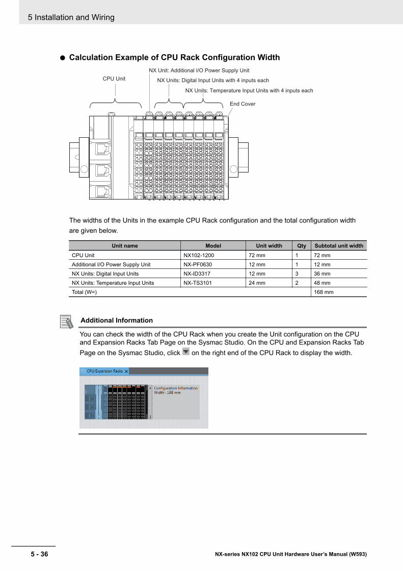
l Calculation Example of CPU Rack Configuration Width
CPU Unit
NX Unit: Additional I/O Power Supply Unit
End Cover
NX Units: Digital Input Units with 4 inputs each
NX Units: Temperature Input Units with 4 inputs each
The widths of the Units in the example CPU Rack configuration and the total configuration widthare given below.
Unit name Model Unit width Qty Subtotal unit widthCPU Unit NX102-1200 72 mm 1 72 mmAdditional I/O Power Supply Unit NX-PF0630 12 mm 1 12 mmNX Units: Digital Input Units NX-ID3317 12 mm 3 36 mmNX Units: Temperature Input Units NX-TS3101 24 mm 2 48 mmTotal (W=) 168 mm
Additional Information
You can check the width of the CPU Rack when you create the Unit configuration on the CPUand Expansion Racks Tab Page on the Sysmac Studio. On the CPU and Expansion Racks TabPage on the Sysmac Studio, click on the right end of the CPU Rack to display the width.
5 Installation and Wiring
5 - 36 NX-series NX102 CPU Unit Hardware User’s Manual (W593)
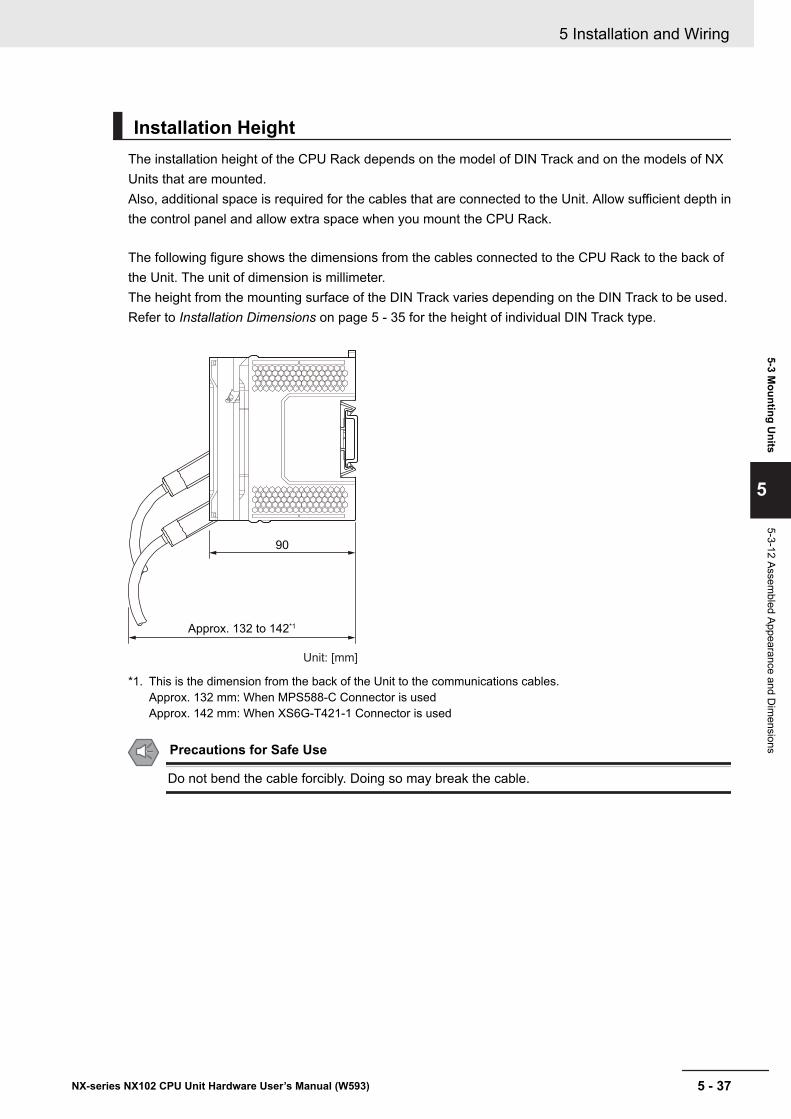
Installation HeightThe installation height of the CPU Rack depends on the model of DIN Track and on the models of NXUnits that are mounted.Also, additional space is required for the cables that are connected to the Unit. Allow sufficient depth inthe control panel and allow extra space when you mount the CPU Rack.
The following figure shows the dimensions from the cables connected to the CPU Rack to the back ofthe Unit. The unit of dimension is millimeter.The height from the mounting surface of the DIN Track varies depending on the DIN Track to be used.Refer to Installation Dimensions on page 5 - 35 for the height of individual DIN Track type.
90
Approx. 132 to 142*1
Unit: [mm]
*1. This is the dimension from the back of the Unit to the communications cables.Approx. 132 mm: When MPS588-C Connector is usedApprox. 142 mm: When XS6G-T421-1 Connector is used
Precautions for Safe Use
Do not bend the cable forcibly. Doing so may break the cable.
5 Installation and Wiring
5 - 37NX-series NX102 CPU Unit Hardware User’s Manual (W593)
5-3 Mounting U
nits
5
5-3-12 Assembled Appearance and D
imensions
5-4 Wiring
WARNING• Do not input a voltage or current that exceeds the specified range in-
to a Unit or slave. If a voltage or current that is outside the specifiedrange is input, the Unit or slave may fail or a fire may occur.
Caution• Tighten terminal block screws and cable screws to the torques speci-
fied in this manual or in the reference manuals. The loose screwsmay result in fire or malfunction.
• Do not touch devices while power is supplied or immediately after thepower supply is turned OFF. You may be burnt.
Precautions for Safe Use
Use the methods that are specified in this manual for wiring the terminal blocks.
Precautions for Correct Use
Do not allow wire clippings or shavings to enter any Unit. Otherwise, Unit burning, failure, ormalfunction may occur. Cover the Units or take other suitable countermeasures, especially dur-ing wiring work.
5 Installation and Wiring
5 - 38 NX-series NX102 CPU Unit Hardware User’s Manual (W593)
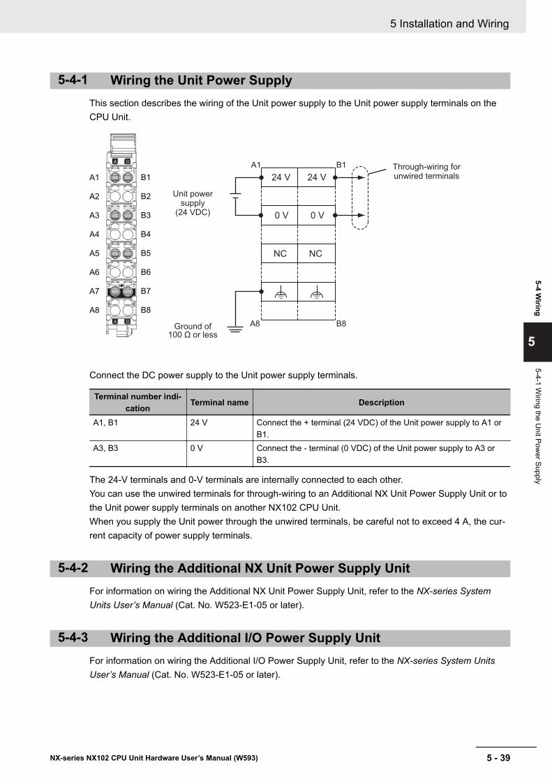
5-4-1 Wiring the Unit Power SupplyThis section describes the wiring of the Unit power supply to the Unit power supply terminals on theCPU Unit.
Unit power supply
(24 VDC)
Through-wiring for unwired terminals
Ground of 100 Ω or less
NC
0 V
24 V
NC
24 V
0 V
A1 B1
A1
A2
A3
A4
A5
A6
A7
A8
B1
B2
B3
B4
B5
B6
B7
B8
A8 B8
Connect the DC power supply to the Unit power supply terminals.
Terminal number indi-cation Terminal name Description
A1, B1 24 V Connect the + terminal (24 VDC) of the Unit power supply to A1 orB1.
A3, B3 0 V Connect the - terminal (0 VDC) of the Unit power supply to A3 orB3.
The 24-V terminals and 0-V terminals are internally connected to each other.You can use the unwired terminals for through-wiring to an Additional NX Unit Power Supply Unit or tothe Unit power supply terminals on another NX102 CPU Unit.When you supply the Unit power through the unwired terminals, be careful not to exceed 4 A, the cur-rent capacity of power supply terminals.
5-4-2 Wiring the Additional NX Unit Power Supply UnitFor information on wiring the Additional NX Unit Power Supply Unit, refer to the NX-series SystemUnits User’s Manual (Cat. No. W523-E1-05 or later).
5-4-3 Wiring the Additional I/O Power Supply UnitFor information on wiring the Additional I/O Power Supply Unit, refer to the NX-series System UnitsUser’s Manual (Cat. No. W523-E1-05 or later).
5 Installation and Wiring
5 - 39NX-series NX102 CPU Unit Hardware User’s Manual (W593)
5-4 Wiring
5
5-4-1 Wiring the U
nit Power Supply
5-4-4 Wiring the Protective DevicesFor information on wiring the protective devices to protect against short circuits and overcurrents ofexternal circuits, refer to 4-4-3 Selecting Protective Devices on page 4 - 21.
5 Installation and Wiring
5 - 40 NX-series NX102 CPU Unit Hardware User’s Manual (W593)
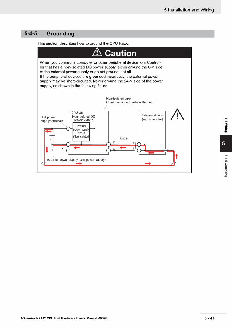
5-4-5 GroundingThis section describes how to ground the CPU Rack.
CautionWhen you connect a computer or other peripheral device to a Control-ler that has a non-isolated DC power supply, either ground the 0-V sideof the external power supply or do not ground it at all.If the peripheral devices are grounded incorrectly, the external powersupply may be short-circuited. Never ground the 24-V side of the powersupply, as shown in the following figure.
Internal power supply
circuit (Non-isolated)
CPU Unit
Cable
External device
(e.g. computer)
External power supply (Unit power supply)
Non-isolated type
Communication Interface Unit, etc.
Unit power
supply terminals
Non-isolated DC power supply
5 Installation and Wiring
5 - 41NX-series NX102 CPU Unit Hardware User’s Manual (W593)
5-4 Wiring
5
5-4-5 Grounding
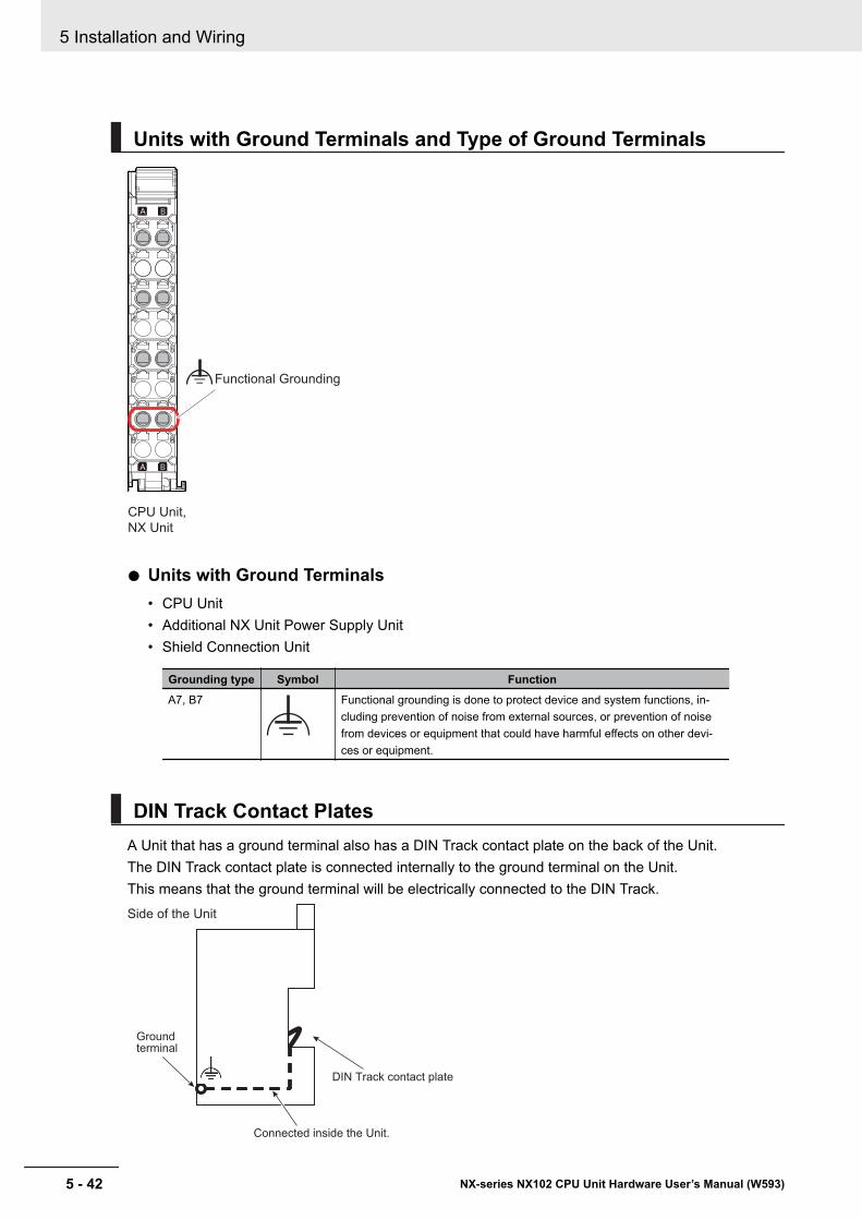
Units with Ground Terminals and Type of Ground Terminals
CPU Unit,
NX Unit
Functional Grounding
l Units with Ground Terminals• CPU Unit• Additional NX Unit Power Supply Unit• Shield Connection Unit
Grounding type Symbol FunctionA7, B7 Functional grounding is done to protect device and system functions, in-
cluding prevention of noise from external sources, or prevention of noisefrom devices or equipment that could have harmful effects on other devi-ces or equipment.
DIN Track Contact PlatesA Unit that has a ground terminal also has a DIN Track contact plate on the back of the Unit.The DIN Track contact plate is connected internally to the ground terminal on the Unit.This means that the ground terminal will be electrically connected to the DIN Track.
DIN Track contact plate
Ground terminal
Side of the Unit
Connected inside the Unit.
5 Installation and Wiring
5 - 42 NX-series NX102 CPU Unit Hardware User’s Manual (W593)

Grounding the CPU RackThis section describes how to ground the ground terminals on the CPU Rack.The functional ground terminals that are provided on some Units and the DIN Track are grounded.
DIN Track
CPU Unit
Electrically connected to
the DIN Track through the
DIN Track contact plate.
Additional NX Unit Power Supply Unit
Shield Connection Unit
End CoverGround terminal
(Functional ground terminal)
Ground terminal
(Functional ground
terminal)
Ground
• Using a dedicated ground wire, ground the ground terminals and DIN Track with a ground resist-ance of 100 Ω or less.
• The ground wire should not be more than 20 m long.
• Use a ground wire that is 2.0 mm2 or larger. CPU Unit Refer to 5-4-8 Wiring to the CPU Unit Termi-nal Block on page 5 - 46 for information on ground wires that are applicable to the functionalground terminal. For information on ground wires that are applicable to the functional ground termi-nals on the Additional NX Unit Power Supply Unit or Shield Connection Unit, refer to the NX-seriesSystem Units User’s Manual (Cat. No. W523).
If the DIN Track is made of steel and the surface is not treated to produce an insulating material, youcan omit grounding the functional ground terminal on any Unit that has one, as shown in the followingfigures.
Additional NX Unit Power Supply Unit
DIN Track
Ground
Ground terminal
(Functional ground terminal)
Ground terminal
(Functional ground terminal)
End Cover
Shield Connection UnitCPU Unit
Electrically connected to
the DIN Track through the
DIN Track contact plate.
5 Installation and Wiring
5 - 43NX-series NX102 CPU Unit Hardware User’s Manual (W593)
5-4 Wiring
5
5-4-5 Grounding
If the surface of the DIN Track is treated to produce an insulating material (e.g., anodized aluminum),the DIN Track contact plate will not be electrically connected to the DIN Track even if they are in physi-cal contact.
Grounding the DIN TrackAttach a crimped terminal to the ground wire and then connect it to mounting hole on the DIN Trackwith a screw to ground the DIN Track.
Grounding the CPU Rack with Peripheral Devices and in ControlPanels
Refer to 5-5-6 Grounding on page 5 - 69 for the grounding procedures for the CPU Rack with periph-eral devices and in control panels.
5 Installation and Wiring
5 - 44 NX-series NX102 CPU Unit Hardware User’s Manual (W593)
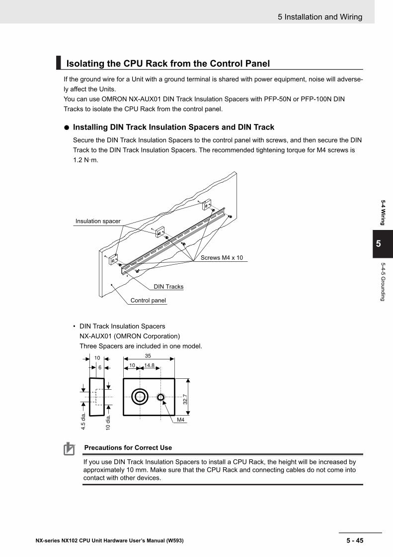
Isolating the CPU Rack from the Control PanelIf the ground wire for a Unit with a ground terminal is shared with power equipment, noise will adverse-ly affect the Units.You can use OMRON NX-AUX01 DIN Track Insulation Spacers with PFP-50N or PFP-100N DINTracks to isolate the CPU Rack from the control panel.
l Installing DIN Track Insulation Spacers and DIN TrackSecure the DIN Track Insulation Spacers to the control panel with screws, and then secure the DINTrack to the DIN Track Insulation Spacers. The recommended tightening torque for M4 screws is1.2 N·m.
Insulation spacer
Control panel
DIN Tracks
Screws M4 x 10
• DIN Track Insulation SpacersNX-AUX01 (OMRON Corporation)Three Spacers are included in one model.
35
14.810
32
.7
4.5
dia
.
6
10
M4
10
dia
.
Precautions for Correct Use
If you use DIN Track Insulation Spacers to install a CPU Rack, the height will be increased byapproximately 10 mm. Make sure that the CPU Rack and connecting cables do not come intocontact with other devices.
5 Installation and Wiring
5 - 45NX-series NX102 CPU Unit Hardware User’s Manual (W593)
5-4 Wiring
5
5-4-5 Grounding
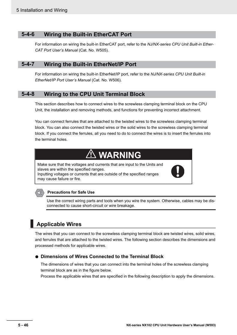
5-4-6 Wiring the Built-in EtherCAT PortFor information on wiring the built-in EtherCAT port, refer to the NJ/NX-series CPU Unit Built-in Ether-CAT Port User’s Manual (Cat. No. W505).
5-4-7 Wiring the Built-in EtherNet/IP PortFor information on wiring the built-in EtherNet/IP port, refer to the NJ/NX-series CPU Unit Built-inEtherNet/IP Port User’s Manual (Cat. No. W506).
5-4-8 Wiring to the CPU Unit Terminal BlockThis section describes how to connect wires to the screwless clamping terminal block on the CPUUnit, the installation and removing methods, and functions for preventing incorrect attachment.
You can connect ferrules that are attached to the twisted wires to the screwless clamping terminalblock. You can also connect the twisted wires or the solid wires to the screwless clamping terminalblock. If you connect the ferrules, all you need to do to connect the wires is to insert the ferrules intothe terminal holes.
WARNINGMake sure that the voltages and currents that are input to the Units andslaves are within the specified ranges.Inputting voltages or currents that are outside of the specified rangesmay cause failure or fire.
Precautions for Safe Use
Use the correct wiring parts and tools when you wire the system. Otherwise, cables may be dis-connected to cause short-circuit or wire breakage.
Applicable WiresThe wires that you can connect to the screwless clamping terminal block are twisted wires, solid wires,and ferrules that are attached to the twisted wires. The following section describes the dimensions andprocessed methods for applicable wires.
l Dimensions of Wires Connected to the Terminal BlockThe dimensions of wires that you can connect into the terminal holes of the screwless clampingterminal block are as in the figure below.Process the applicable wires that are specified in the following description to apply the dimensions.
5 Installation and Wiring
5 - 46 NX-series NX102 CPU Unit Hardware User’s Manual (W593)
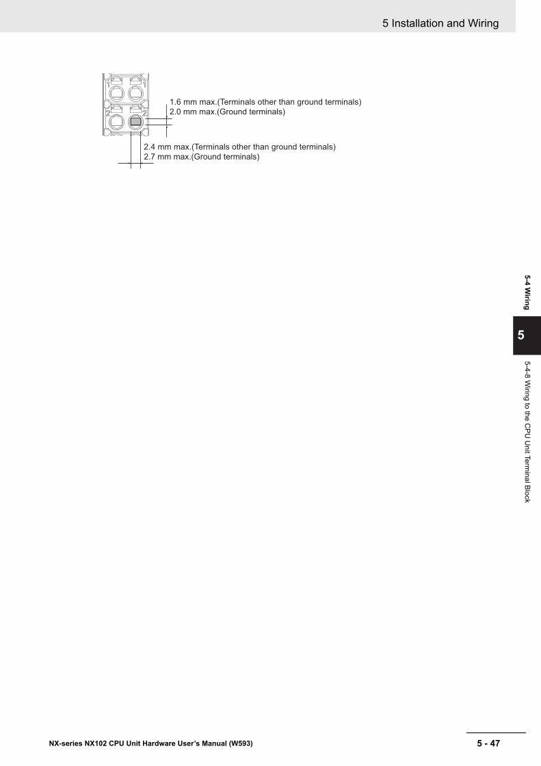
1.6 mm max.(Terminals other than ground terminals)
2.0 mm max.(Ground terminals)
2.4 mm max.(Terminals other than ground terminals)
2.7 mm max.(Ground terminals)
5 Installation and Wiring
5 - 47NX-series NX102 CPU Unit Hardware User’s Manual (W593)
5-4 Wiring
5
5-4-8 Wiring to the C
PU U
nit Terminal Block
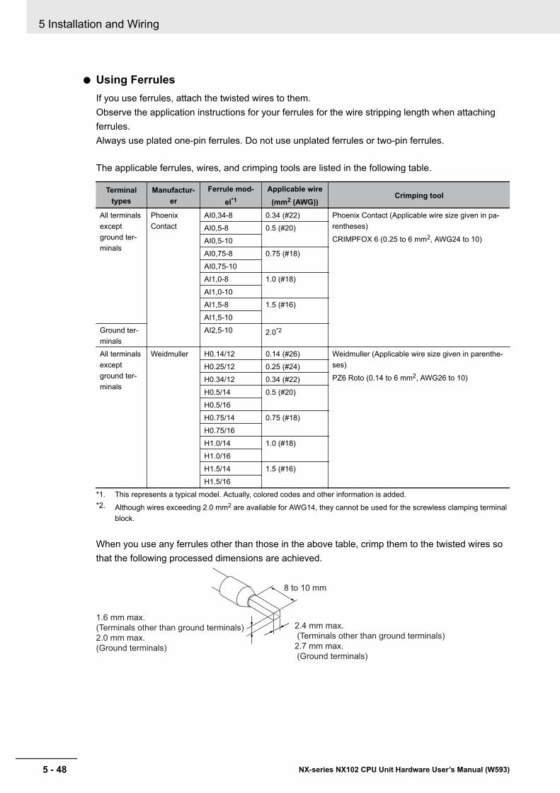
l Using FerrulesIf you use ferrules, attach the twisted wires to them.Observe the application instructions for your ferrules for the wire stripping length when attachingferrules.Always use plated one-pin ferrules. Do not use unplated ferrules or two-pin ferrules.
The applicable ferrules, wires, and crimping tools are listed in the following table.
Terminaltypes
Manufactur-er
Ferrule mod-el*1
Applicable wire(mm2 (AWG))
Crimping tool
All terminalsexceptground ter-minals
PhoenixContact
AI0,34-8 0.34 (#22) Phoenix Contact (Applicable wire size given in pa-rentheses)
CRIMPFOX 6 (0.25 to 6 mm2, AWG24 to 10)AI0,5-8 0.5 (#20)AI0,5-10AI0,75-8 0.75 (#18)AI0,75-10AI1,0-8 1.0 (#18)AI1,0-10AI1,5-8 1.5 (#16)AI1,5-10
Ground ter-minals
AI2,5-10 2.0*2
All terminalsexceptground ter-minals
Weidmuller H0.14/12 0.14 (#26) Weidmuller (Applicable wire size given in parenthe-ses)
PZ6 Roto (0.14 to 6 mm2, AWG26 to 10)H0.25/12 0.25 (#24)H0.34/12 0.34 (#22)H0.5/14 0.5 (#20)H0.5/16H0.75/14 0.75 (#18)H0.75/16H1.0/14 1.0 (#18)H1.0/16H1.5/14 1.5 (#16)H1.5/16
*1. This represents a typical model. Actually, colored codes and other information is added.*2. Although wires exceeding 2.0 mm2 are available for AWG14, they cannot be used for the screwless clamping terminal
block.
When you use any ferrules other than those in the above table, crimp them to the twisted wires sothat the following processed dimensions are achieved.
8 to 10 mm
2.4 mm max.
(Terminals other than ground terminals)
2.7 mm max.
(Ground terminals)
1.6 mm max.
(Terminals other than ground terminals)
2.0 mm max.
(Ground terminals)
5 Installation and Wiring
5 - 48 NX-series NX102 CPU Unit Hardware User’s Manual (W593)

l Using Twisted or Solid WiresIf you use twisted wires or solid wires, use the following table to determine the correct wire specifi-cations.
TerminalsWire type
Wire size
Conductorlength
(strippinglength)
Twisted wires Solid wire
ClassificationCurrent ca-
pacityPlated
Unplat-ed
PlatedUnplat-
edAll terminalsexcept groundterminals
2 A max. Possible Possible Possible Possible 0.08 to 1.5 mm2
(AWG 28 to 16)
8 to 10 mmGreater than 2A and 4 A orless
Not pos-sible
Possible*1
Not pos-sible
Ground termi-nals
--- Possible Possible Possible Possible 2.0 mm2 10 to 12 mm
*1. Secure wires to the screwless clamping terminal block. Refer to Securing Wires on page 5 - 52 for how to securewires.
Precautions for Correct Use
• Use cables with suitable wire sizes for the carrying current. There are also restrictions on thecurrent due to the ambient temperature. Refer to the manuals for the cables and use the ca-bles correctly for the operating environment.
• For twisted wires, strip the sheath and twist the conductor portion. Do not unravel or bend theconductor portion of twisted wires or solid wires.
Unravel wires Bend wires
NG NG
Additional Information
If more than 2 A will flow on the wires, use plated wires or use ferrules.
5 Installation and Wiring
5 - 49NX-series NX102 CPU Unit Hardware User’s Manual (W593)
5-4 Wiring
5
5-4-8 Wiring to the C
PU U
nit Terminal Block
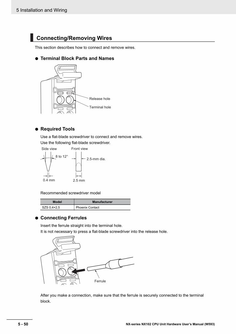
Connecting/Removing WiresThis section describes how to connect and remove wires.
l Terminal Block Parts and Names
Terminal hole
Release hole
l Required ToolsUse a flat-blade screwdriver to connect and remove wires.Use the following flat-blade screwdriver.
2.5 mm0.4 mm
Front view
8 to 12°
Side view
2.5-mm dia.
Recommended screwdriver model
Model ManufacturerSZS 0,4×2,5 Phoenix Contact
l Connecting FerrulesInsert the ferrule straight into the terminal hole.It is not necessary to press a flat-blade screwdriver into the release hole.
Ferrule
After you make a connection, make sure that the ferrule is securely connected to the terminalblock.
5 Installation and Wiring
5 - 50 NX-series NX102 CPU Unit Hardware User’s Manual (W593)
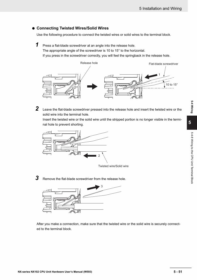
l Connecting Twisted Wires/Solid WiresUse the following procedure to connect the twisted wires or solid wires to the terminal block.
1 Press a flat-blade screwdriver at an angle into the release hole.The appropriate angle of the screwdriver is 10 to 15° to the horizontal.If you press in the screwdriver correctly, you will feel the springback in the release hole.
1
10 to 15°
Flat-blade screwdriverRelease hole
2 Leave the flat-blade screwdriver pressed into the release hole and insert the twisted wire or thesolid wire into the terminal hole.Insert the twisted wire or the solid wire until the stripped portion is no longer visible in the termi-nal hole to prevent shorting.
2
Twisted wire/Solid wire
3 Remove the flat-blade screwdriver from the release hole.
3
After you make a connection, make sure that the twisted wire or the solid wire is securely connect-ed to the terminal block.
5 Installation and Wiring
5 - 51NX-series NX102 CPU Unit Hardware User’s Manual (W593)
5-4 Wiring
5
5-4-8 Wiring to the C
PU U
nit Terminal Block
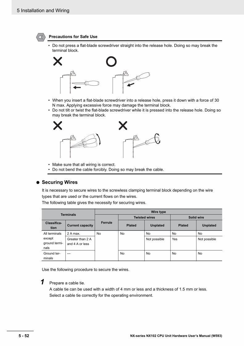
Precautions for Safe Use
• Do not press a flat-blade screwdriver straight into the release hole. Doing so may break theterminal block.
• When you insert a flat-blade screwdriver into a release hole, press it down with a force of 30N max. Applying excessive force may damage the terminal block.
• Do not tilt or twist the flat-blade screwdriver while it is pressed into the release hole. Doing somay break the terminal block.
• Make sure that all wiring is correct.• Do not bend the cable forcibly. Doing so may break the cable.
l Securing WiresIt is necessary to secure wires to the screwless clamping terminal block depending on the wiretypes that are used or the current flows on the wires.The following table gives the necessity for securing wires.
TerminalsWire type
FerruleTwisted wires Solid wire
Classifica-tion
Current capacity Plated Unplated Plated Unplated
All terminalsexceptground termi-nals
2 A max. No No No No NoGreater than 2 Aand 4 A or less
Not possible Yes Not possible
Ground ter-minals
--- No No No No
Use the following procedure to secure the wires.
1 Prepare a cable tie.A cable tie can be used with a width of 4 mm or less and a thickness of 1.5 mm or less.Select a cable tie correctly for the operating environment.
5 Installation and Wiring
5 - 52 NX-series NX102 CPU Unit Hardware User’s Manual (W593)
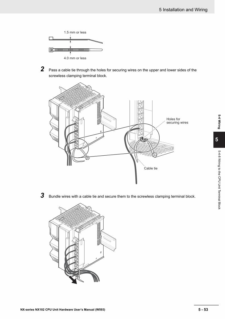
1.5 mm or less
4.0 mm or less
2 Pass a cable tie through the holes for securing wires on the upper and lower sides of thescrewless clamping terminal block.
Holes for securing wires
Cable tie
3 Bundle wires with a cable tie and secure them to the screwless clamping terminal block.
5 Installation and Wiring
5 - 53NX-series NX102 CPU Unit Hardware User’s Manual (W593)
5-4 Wiring
5
5-4-8 Wiring to the C
PU U
nit Terminal Block
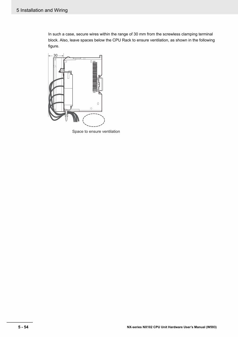
In such a case, secure wires within the range of 30 mm from the screwless clamping terminalblock. Also, leave spaces below the CPU Rack to ensure ventilation, as shown in the followingfigure.
30
Space to ensure ventilation
5 Installation and Wiring
5 - 54 NX-series NX102 CPU Unit Hardware User’s Manual (W593)
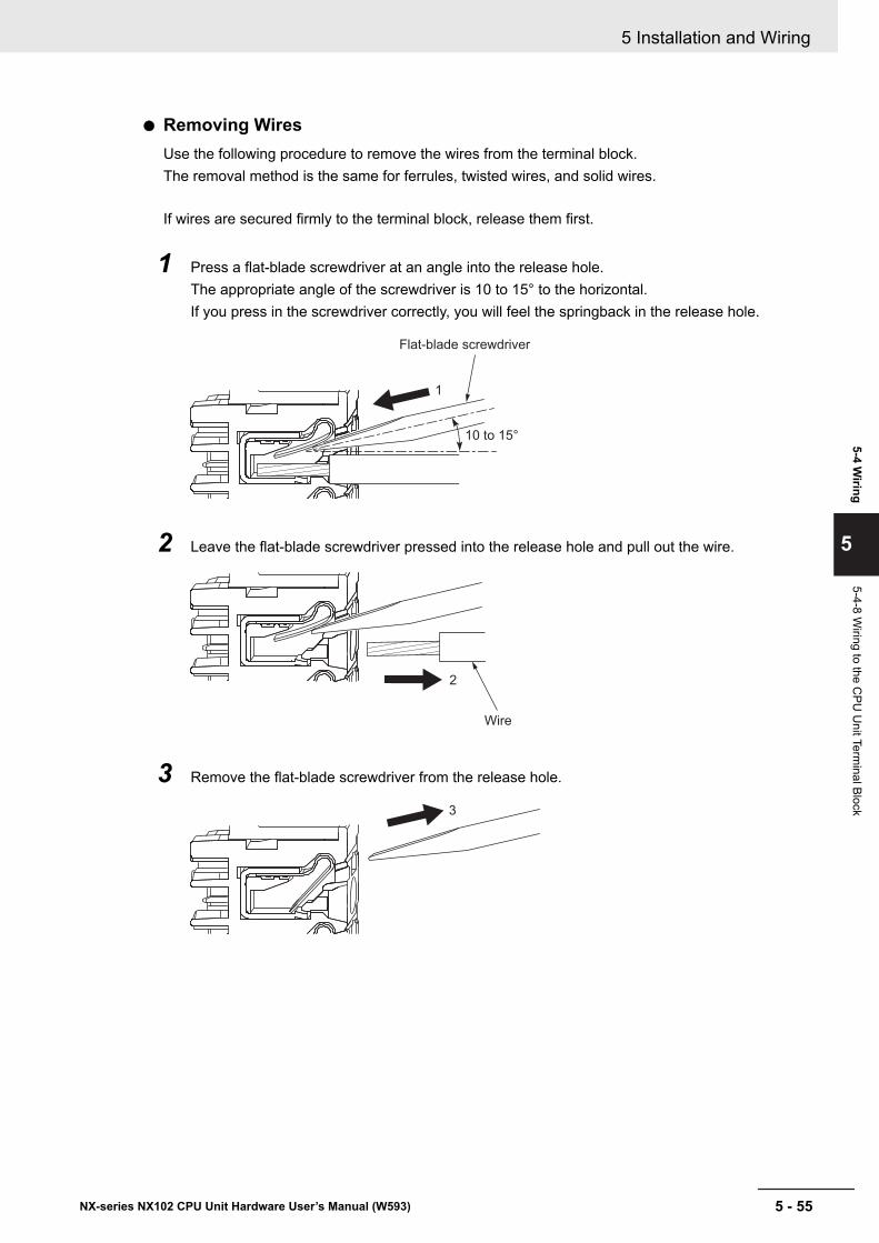
l Removing WiresUse the following procedure to remove the wires from the terminal block.The removal method is the same for ferrules, twisted wires, and solid wires.
If wires are secured firmly to the terminal block, release them first.
1 Press a flat-blade screwdriver at an angle into the release hole.The appropriate angle of the screwdriver is 10 to 15° to the horizontal.If you press in the screwdriver correctly, you will feel the springback in the release hole.
Flat-blade screwdriver
1
10 to 15°
2 Leave the flat-blade screwdriver pressed into the release hole and pull out the wire.
2
Wire
3 Remove the flat-blade screwdriver from the release hole.
3
5 Installation and Wiring
5 - 55NX-series NX102 CPU Unit Hardware User’s Manual (W593)
5-4 Wiring
5
5-4-8 Wiring to the C
PU U
nit Terminal Block
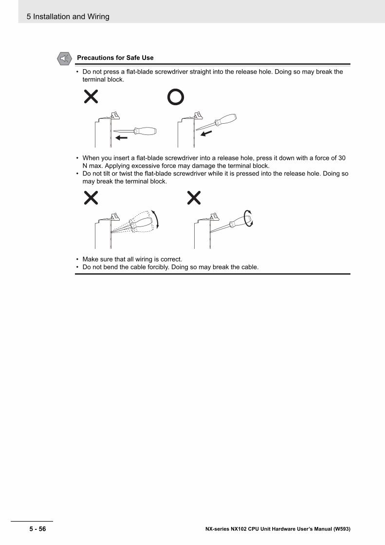
Precautions for Safe Use
• Do not press a flat-blade screwdriver straight into the release hole. Doing so may break theterminal block.
• When you insert a flat-blade screwdriver into a release hole, press it down with a force of 30N max. Applying excessive force may damage the terminal block.
• Do not tilt or twist the flat-blade screwdriver while it is pressed into the release hole. Doing somay break the terminal block.
• Make sure that all wiring is correct.• Do not bend the cable forcibly. Doing so may break the cable.
5 Installation and Wiring
5 - 56 NX-series NX102 CPU Unit Hardware User’s Manual (W593)
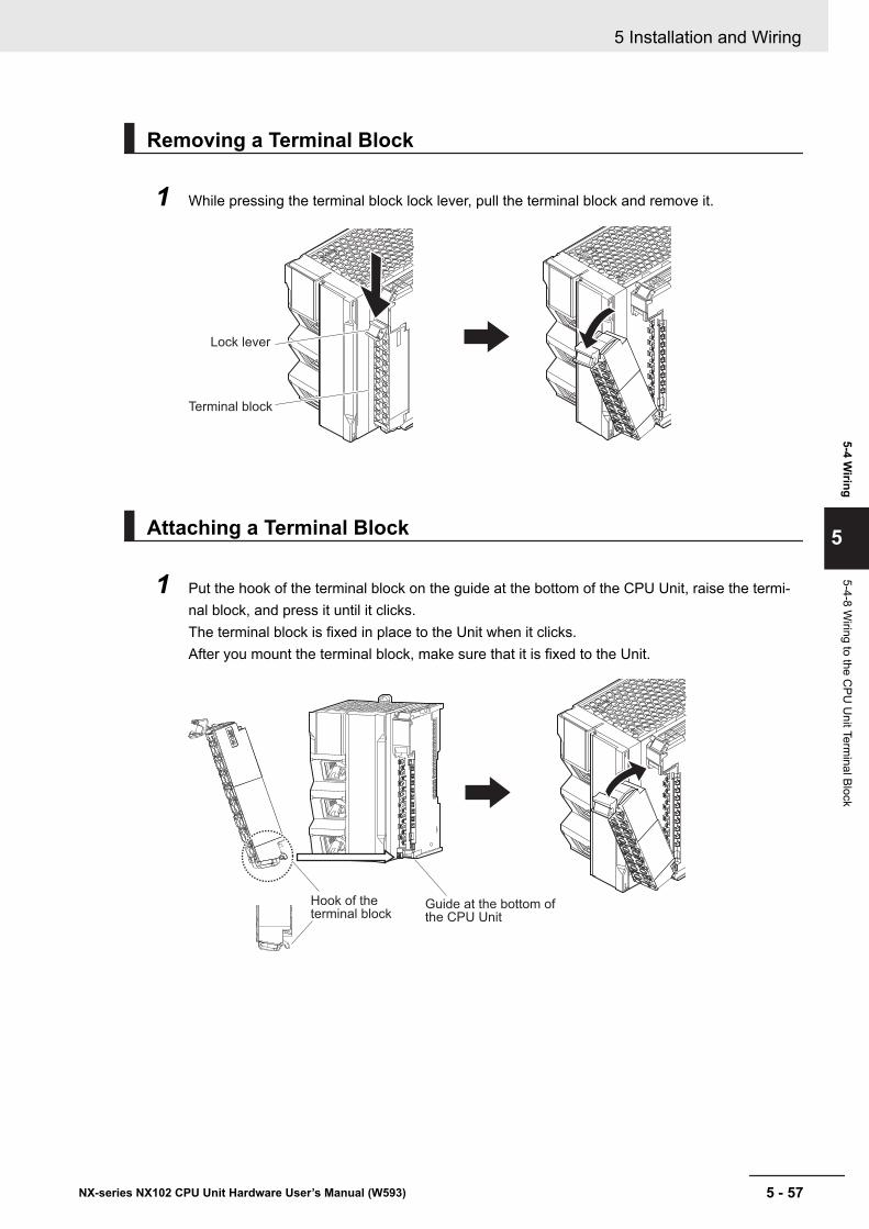
Removing a Terminal Block
1 While pressing the terminal block lock lever, pull the terminal block and remove it.
Terminal block
Lock lever
Attaching a Terminal Block
1 Put the hook of the terminal block on the guide at the bottom of the CPU Unit, raise the termi-nal block, and press it until it clicks.The terminal block is fixed in place to the Unit when it clicks.After you mount the terminal block, make sure that it is fixed to the Unit.
Guide at the bottom of
the CPU Unit
Hook of the
terminal block
5 Installation and Wiring
5 - 57NX-series NX102 CPU Unit Hardware User’s Manual (W593)
5-4 Wiring
5
5-4-8 Wiring to the C
PU U
nit Terminal Block
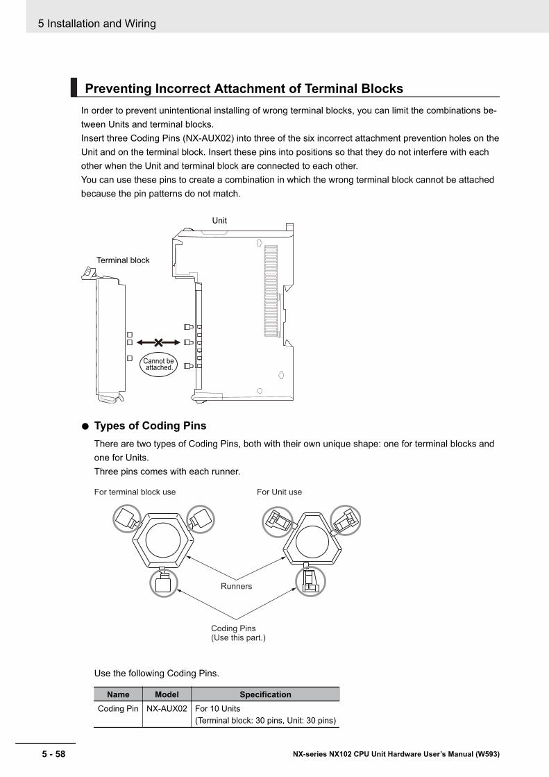
Preventing Incorrect Attachment of Terminal BlocksIn order to prevent unintentional installing of wrong terminal blocks, you can limit the combinations be-tween Units and terminal blocks.Insert three Coding Pins (NX-AUX02) into three of the six incorrect attachment prevention holes on theUnit and on the terminal block. Insert these pins into positions so that they do not interfere with eachother when the Unit and terminal block are connected to each other.You can use these pins to create a combination in which the wrong terminal block cannot be attachedbecause the pin patterns do not match.
Terminal block
Unit
Cannot be attached.
l Types of Coding PinsThere are two types of Coding Pins, both with their own unique shape: one for terminal blocks andone for Units.Three pins comes with each runner.
For terminal block use For Unit use
Coding Pins(Use this part.)
Runners
Use the following Coding Pins.
Name Model SpecificationCoding Pin NX-AUX02 For 10 Units
(Terminal block: 30 pins, Unit: 30 pins)
5 Installation and Wiring
5 - 58 NX-series NX102 CPU Unit Hardware User’s Manual (W593)
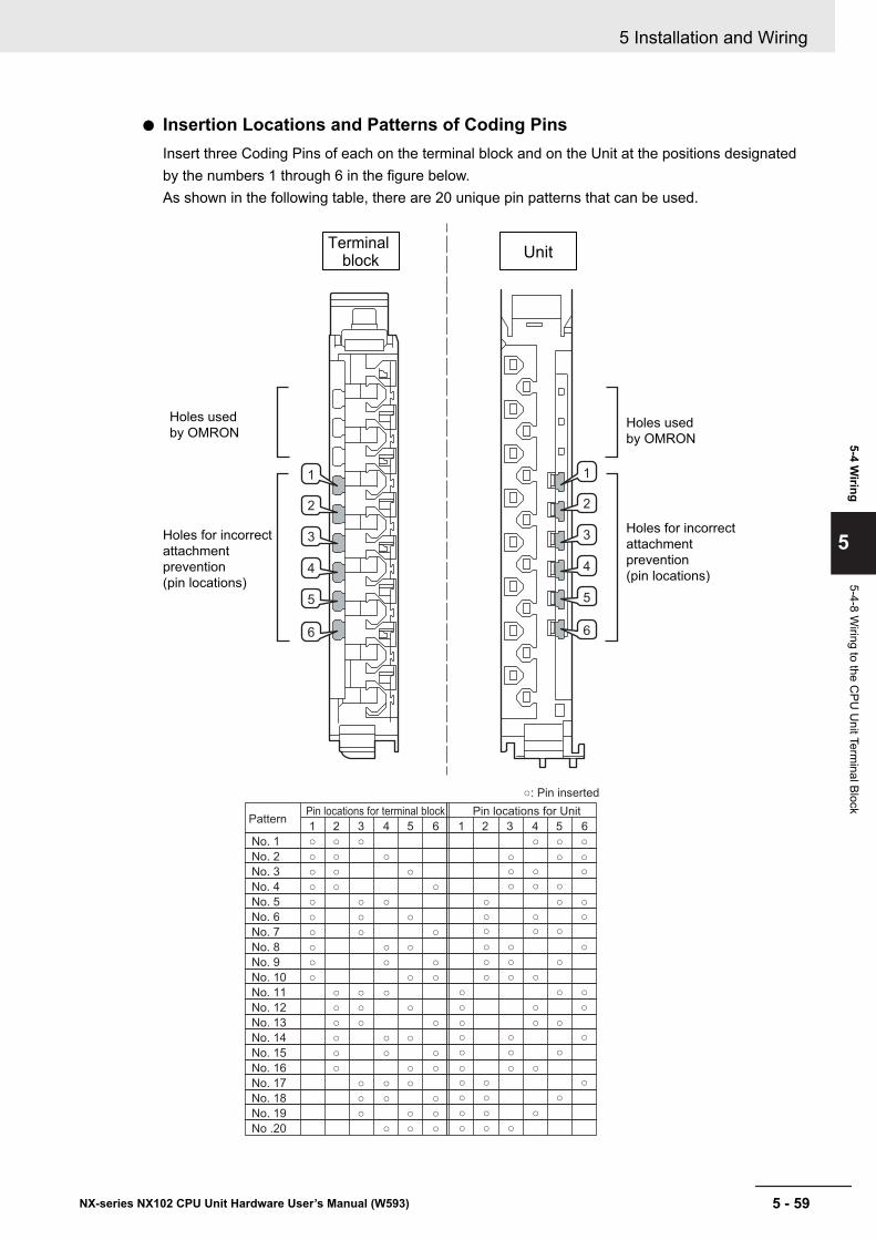
l Insertion Locations and Patterns of Coding PinsInsert three Coding Pins of each on the terminal block and on the Unit at the positions designatedby the numbers 1 through 6 in the figure below.As shown in the following table, there are 20 unique pin patterns that can be used.
1 2 3 4 5 6
No. 1
No. 2
No. 3
No. 4
No. 5
No. 6
No. 7
No. 8
No. 9
No. 10
No. 11
No. 12
No. 13
No. 14
No. 15
No. 16
No. 17
No. 18
No. 19
No .20
1 2 3 4 5 6
PatternPin locations for terminal block Pin locations for Unit
: Pin inserted
Unit Terminal
block
1
2
3
4
5
6
1
2
3
4
5
6
Holes used
by OMRON
Holes used
by OMRON
Holes for incorrect
attachment
prevention
(pin locations)
Holes for incorrect
attachment
prevention
(pin locations)
5 Installation and Wiring
5 - 59NX-series NX102 CPU Unit Hardware User’s Manual (W593)
5-4 Wiring
5
5-4-8 Wiring to the C
PU U
nit Terminal Block
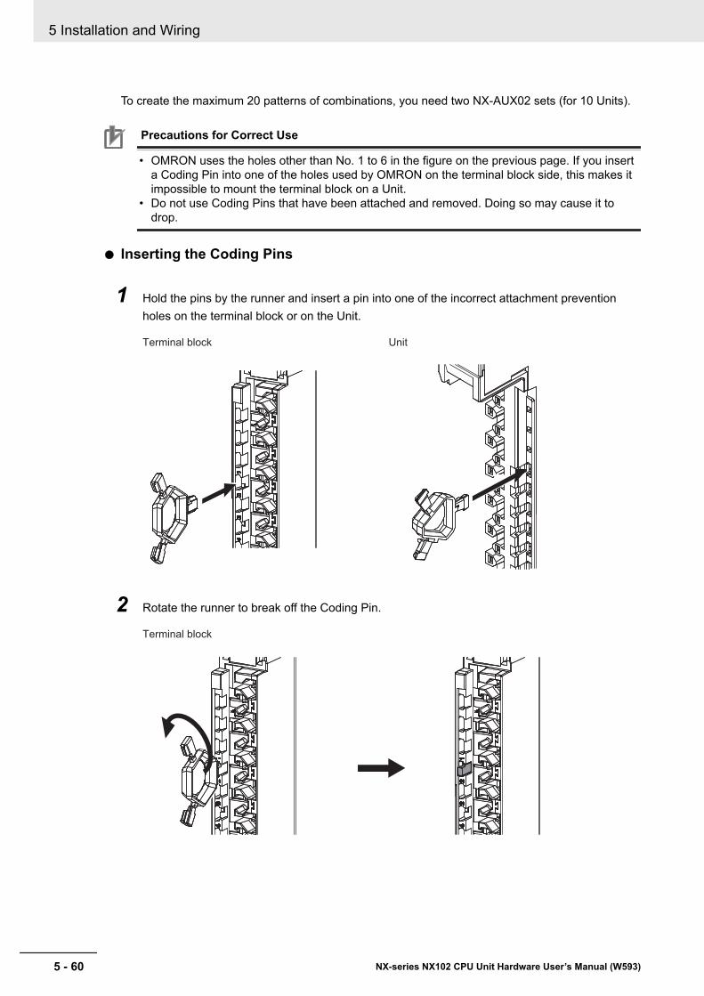
To create the maximum 20 patterns of combinations, you need two NX-AUX02 sets (for 10 Units).
Precautions for Correct Use
• OMRON uses the holes other than No. 1 to 6 in the figure on the previous page. If you inserta Coding Pin into one of the holes used by OMRON on the terminal block side, this makes itimpossible to mount the terminal block on a Unit.
• Do not use Coding Pins that have been attached and removed. Doing so may cause it todrop.
l Inserting the Coding Pins
1 Hold the pins by the runner and insert a pin into one of the incorrect attachment preventionholes on the terminal block or on the Unit.
Terminal block Unit
2 Rotate the runner to break off the Coding Pin.
Terminal block
5 Installation and Wiring
5 - 60 NX-series NX102 CPU Unit Hardware User’s Manual (W593)
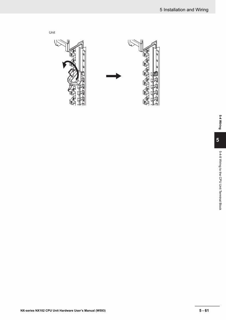
Unit
5 Installation and Wiring
5 - 61NX-series NX102 CPU Unit Hardware User’s Manual (W593)
5-4 Wiring
5
5-4-8 Wiring to the C
PU U
nit Terminal Block
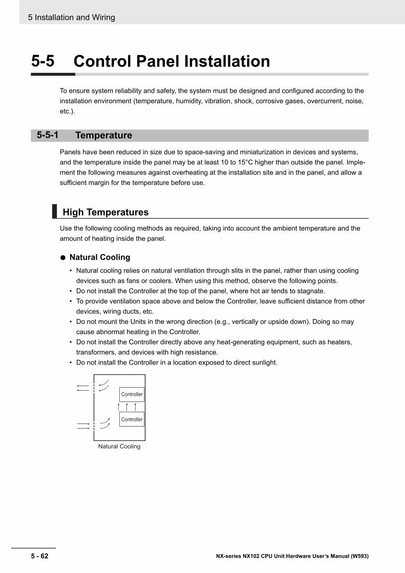
5-5 Control Panel InstallationTo ensure system reliability and safety, the system must be designed and configured according to theinstallation environment (temperature, humidity, vibration, shock, corrosive gases, overcurrent, noise,etc.).
5-5-1 TemperaturePanels have been reduced in size due to space-saving and miniaturization in devices and systems,and the temperature inside the panel may be at least 10 to 15°C higher than outside the panel. Imple-ment the following measures against overheating at the installation site and in the panel, and allow asufficient margin for the temperature before use.
High TemperaturesUse the following cooling methods as required, taking into account the ambient temperature and theamount of heating inside the panel.
l Natural Cooling• Natural cooling relies on natural ventilation through slits in the panel, rather than using cooling
devices such as fans or coolers. When using this method, observe the following points.• Do not install the Controller at the top of the panel, where hot air tends to stagnate.• To provide ventilation space above and below the Controller, leave sufficient distance from other
devices, wiring ducts, etc.• Do not mount the Units in the wrong direction (e.g., vertically or upside down). Doing so may
cause abnormal heating in the Controller.• Do not install the Controller directly above any heat-generating equipment, such as heaters,
transformers, and devices with high resistance.• Do not install the Controller in a location exposed to direct sunlight.
Natural Cooling
Controller
Controller
5 Installation and Wiring
5 - 62 NX-series NX102 CPU Unit Hardware User’s Manual (W593)
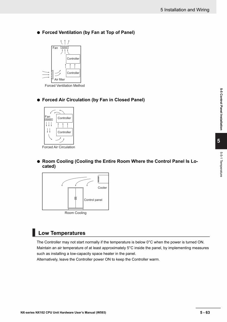
l Forced Ventilation (by Fan at Top of Panel)
Air filter
Fan
Forced Ventilation Method
Controller
Controller
l Forced Air Circulation (by Fan in Closed Panel)
Fan
Forced Air Circulation
Controller
Controller
l Room Cooling (Cooling the Entire Room Where the Control Panel Is Lo-cated)
Room Cooling
Cooler
Control panel
Low TemperaturesThe Controller may not start normally if the temperature is below 0°C when the power is turned ON.Maintain an air temperature of at least approximately 5°C inside the panel, by implementing measuressuch as installing a low-capacity space heater in the panel.Alternatively, leave the Controller power ON to keep the Controller warm.
5 Installation and Wiring
5 - 63NX-series NX102 CPU Unit Hardware User’s Manual (W593)
5-5 Control Panel Installation
5
5-5-1 Temperature
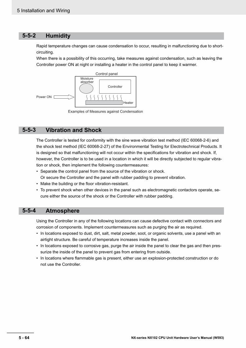
5-5-2 HumidityRapid temperature changes can cause condensation to occur, resulting in malfunctioning due to short-circuiting.When there is a possibility of this occurring, take measures against condensation, such as leaving theController power ON at night or installing a heater in the control panel to keep it warmer.
Moistureabsorber
Power ON
Control panel
Heater
Examples of Measures against Condensation
Controller
5-5-3 Vibration and ShockThe Controller is tested for conformity with the sine wave vibration test method (IEC 60068-2-6) andthe shock test method (IEC 60068-2-27) of the Environmental Testing for Electrotechnical Products. Itis designed so that malfunctioning will not occur within the specifications for vibration and shock. If,however, the Controller is to be used in a location in which it will be directly subjected to regular vibra-tion or shock, then implement the following countermeasures:• Separate the control panel from the source of the vibration or shock.
Or secure the Controller and the panel with rubber padding to prevent vibration.• Make the building or the floor vibration-resistant.• To prevent shock when other devices in the panel such as electromagnetic contactors operate, se-
cure either the source of the shock or the Controller with rubber padding.
5-5-4 AtmosphereUsing the Controller in any of the following locations can cause defective contact with connectors andcorrosion of components. Implement countermeasures such as purging the air as required.• In locations exposed to dust, dirt, salt, metal powder, soot, or organic solvents, use a panel with an
airtight structure. Be careful of temperature increases inside the panel.• In locations exposed to corrosive gas, purge the air inside the panel to clear the gas and then pres-
surize the inside of the panel to prevent gas from entering from outside.• In locations where flammable gas is present, either use an explosion-protected construction or do
not use the Controller.
5 Installation and Wiring
5 - 64 NX-series NX102 CPU Unit Hardware User’s Manual (W593)
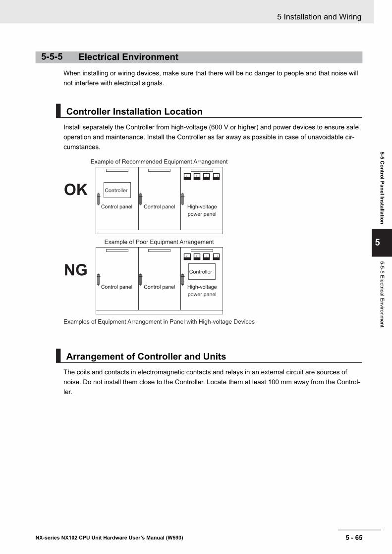
5-5-5 Electrical EnvironmentWhen installing or wiring devices, make sure that there will be no danger to people and that noise willnot interfere with electrical signals.
Controller Installation LocationInstall separately the Controller from high-voltage (600 V or higher) and power devices to ensure safeoperation and maintenance. Install the Controller as far away as possible in case of unavoidable cir-cumstances.
Example of Recommended Equipment Arrangement
Control panel Control panel High-voltage
power panel
Examples of Equipment Arrangement in Panel with High-voltage Devices
Example of Poor Equipment Arrangement
Control panel Control panel High-voltage
power panel
Controller
Controller
OK
NG
Arrangement of Controller and UnitsThe coils and contacts in electromagnetic contacts and relays in an external circuit are sources ofnoise. Do not install them close to the Controller. Locate them at least 100 mm away from the Control-ler.
5 Installation and Wiring
5 - 65NX-series NX102 CPU Unit Hardware User’s Manual (W593)
5-5 Control Panel Installation
5
5-5-5 Electrical Environment
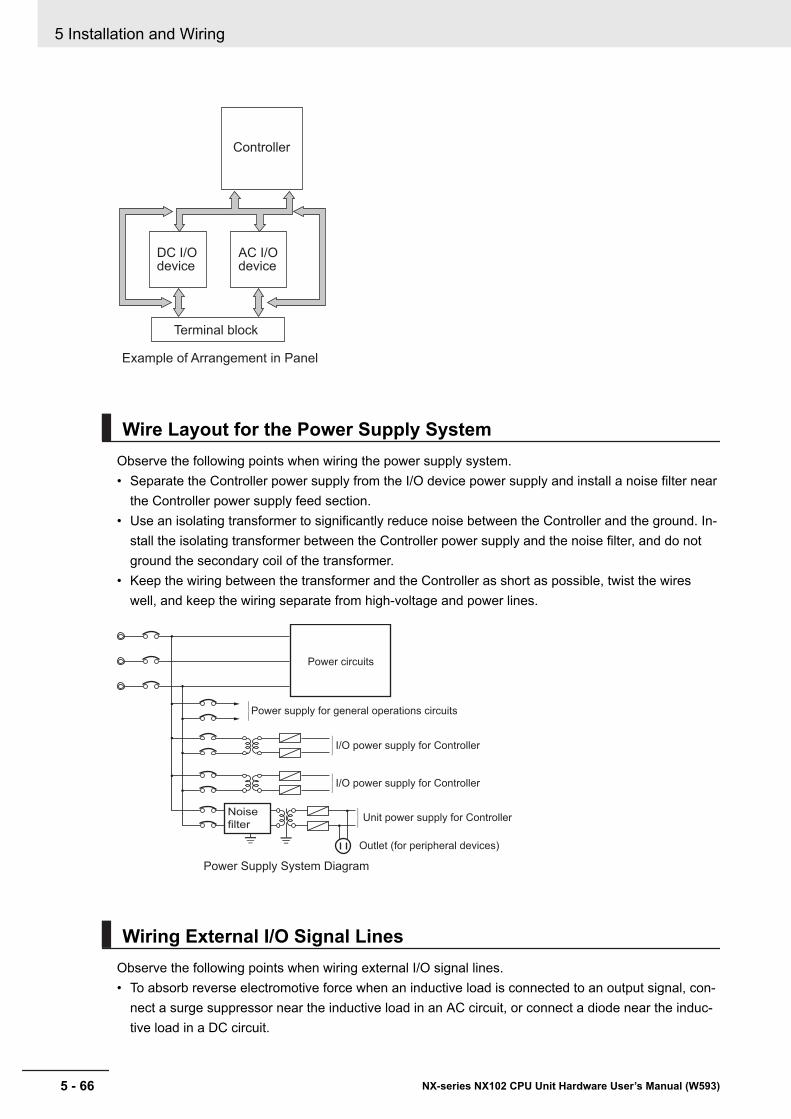
Controller
DC I/Odevice
AC I/Odevice
Terminal block
Example of Arrangement in Panel
Wire Layout for the Power Supply SystemObserve the following points when wiring the power supply system.• Separate the Controller power supply from the I/O device power supply and install a noise filter near
the Controller power supply feed section.• Use an isolating transformer to significantly reduce noise between the Controller and the ground. In-
stall the isolating transformer between the Controller power supply and the noise filter, and do notground the secondary coil of the transformer.
• Keep the wiring between the transformer and the Controller as short as possible, twist the wireswell, and keep the wiring separate from high-voltage and power lines.
Unit power supply for Controller
I/O power supply for Controller
Power Supply System Diagram
Power circuits
Power supply for general operations circuits
Outlet (for peripheral devices)
I/O power supply for Controller
Noise
filter
Wiring External I/O Signal LinesObserve the following points when wiring external I/O signal lines.• To absorb reverse electromotive force when an inductive load is connected to an output signal, con-
nect a surge suppressor near the inductive load in an AC circuit, or connect a diode near the induc-tive load in a DC circuit.
5 Installation and Wiring
5 - 66 NX-series NX102 CPU Unit Hardware User’s Manual (W593)
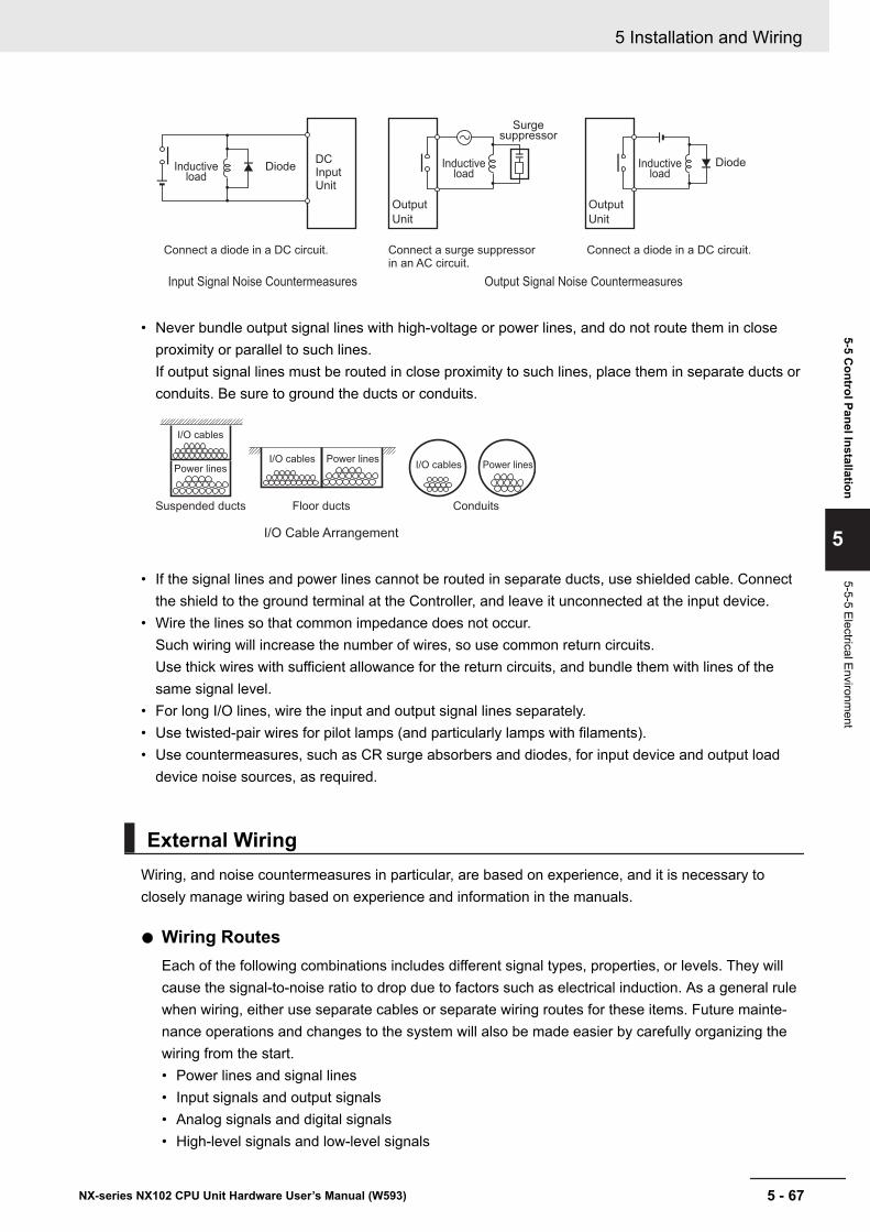
Inductive load
DiodeDC Input Unit
Output
Unit
Inductive load
Surge suppressor
Output
Unit
Diode
Input Signal Noise Countermeasures Output Signal Noise Countermeasures
Connect a diode in a DC circuit. Connect a surge suppressor in an AC circuit.
Connect a diode in a DC circuit.
Inductive load
• Never bundle output signal lines with high-voltage or power lines, and do not route them in closeproximity or parallel to such lines.If output signal lines must be routed in close proximity to such lines, place them in separate ducts orconduits. Be sure to ground the ducts or conduits.
I/O Cable Arrangement
Floor ducts ConduitsSuspended ducts
I/O cables
I/O cablesPower lines
Power linesI/O cables Power lines
• If the signal lines and power lines cannot be routed in separate ducts, use shielded cable. Connectthe shield to the ground terminal at the Controller, and leave it unconnected at the input device.
• Wire the lines so that common impedance does not occur.Such wiring will increase the number of wires, so use common return circuits.Use thick wires with sufficient allowance for the return circuits, and bundle them with lines of thesame signal level.
• For long I/O lines, wire the input and output signal lines separately.• Use twisted-pair wires for pilot lamps (and particularly lamps with filaments).• Use countermeasures, such as CR surge absorbers and diodes, for input device and output load
device noise sources, as required.
External WiringWiring, and noise countermeasures in particular, are based on experience, and it is necessary toclosely manage wiring based on experience and information in the manuals.
l Wiring RoutesEach of the following combinations includes different signal types, properties, or levels. They willcause the signal-to-noise ratio to drop due to factors such as electrical induction. As a general rulewhen wiring, either use separate cables or separate wiring routes for these items. Future mainte-nance operations and changes to the system will also be made easier by carefully organizing thewiring from the start.• Power lines and signal lines• Input signals and output signals• Analog signals and digital signals• High-level signals and low-level signals
5 Installation and Wiring
5 - 67NX-series NX102 CPU Unit Hardware User’s Manual (W593)
5-5 Control Panel Installation
5
5-5-5 Electrical Environment
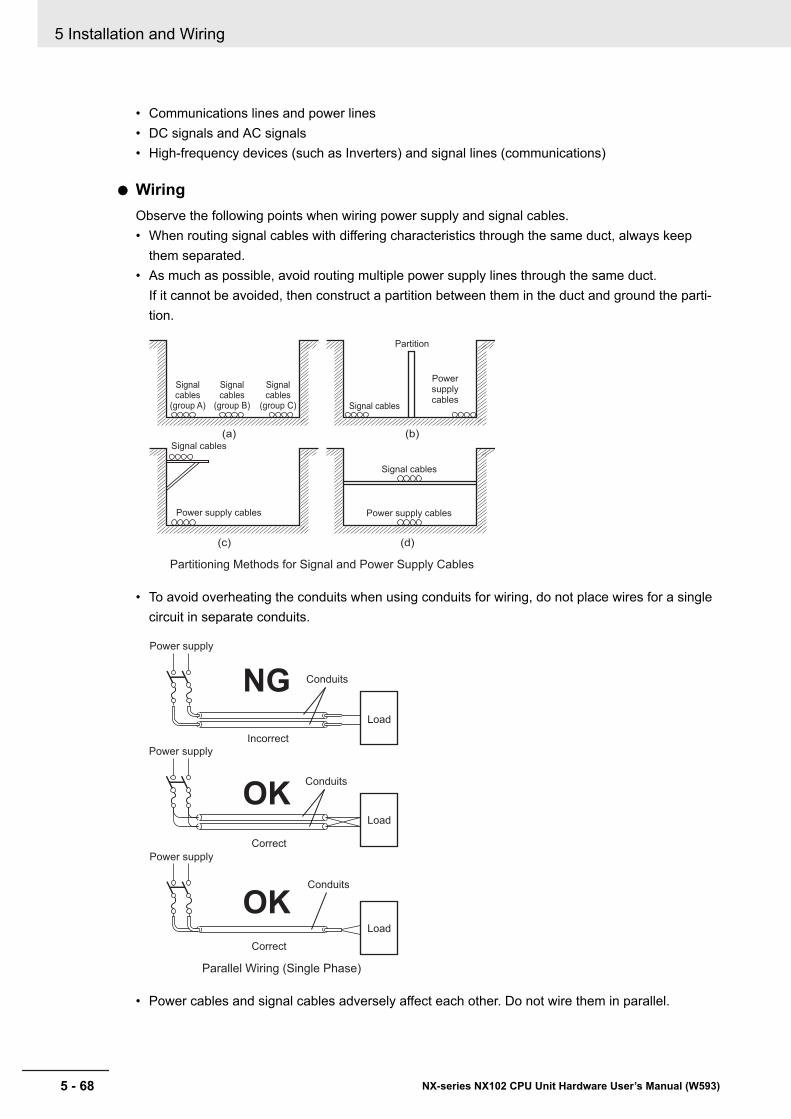
• Communications lines and power lines• DC signals and AC signals• High-frequency devices (such as Inverters) and signal lines (communications)
l WiringObserve the following points when wiring power supply and signal cables.• When routing signal cables with differing characteristics through the same duct, always keep
them separated.• As much as possible, avoid routing multiple power supply lines through the same duct.
If it cannot be avoided, then construct a partition between them in the duct and ground the parti-tion.
Partitioning Methods for Signal and Power Supply Cables
(a) (b)
(c) (d)
Signal cables
Signal cables
Signal cables
Power supply cables
Powersupplycables
Power supply cables
Partition
Signalcables
(group A)
Signalcables
(group B)
Signalcables
(group C)
• To avoid overheating the conduits when using conduits for wiring, do not place wires for a singlecircuit in separate conduits.
Parallel Wiring (Single Phase)
Correct
Correct
Power supply
Incorrect
Power supply
Power supply
Load
Load
Load
Conduits
Conduits
Conduits
OK
OK
NG
• Power cables and signal cables adversely affect each other. Do not wire them in parallel.
5 Installation and Wiring
5 - 68 NX-series NX102 CPU Unit Hardware User’s Manual (W593)
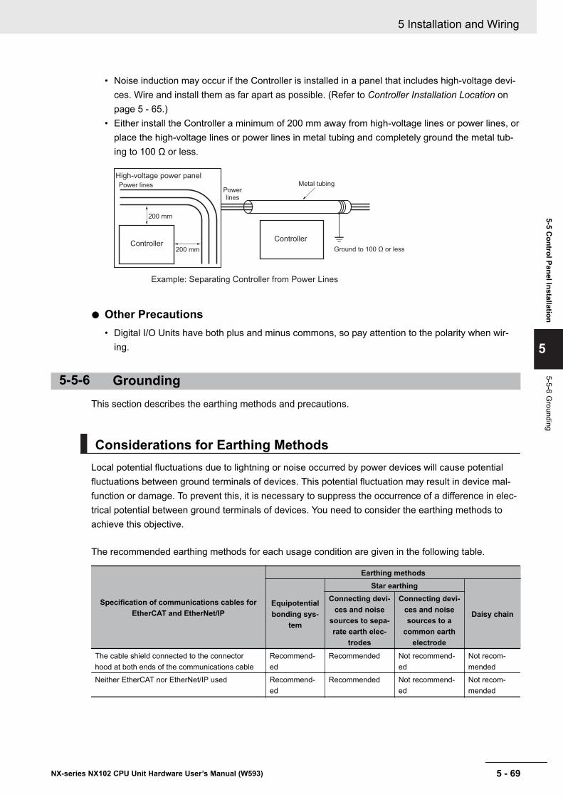
• Noise induction may occur if the Controller is installed in a panel that includes high-voltage devi-ces. Wire and install them as far apart as possible. (Refer to Controller Installation Location onpage 5 - 65.)
• Either install the Controller a minimum of 200 mm away from high-voltage lines or power lines, orplace the high-voltage lines or power lines in metal tubing and completely ground the metal tub-ing to 100 Ω or less.
Example: Separating Controller from Power Lines
Metal tubing
200 mm
200 mm
High-voltage power panel
Power linesPowerlines
Ground to 100 Ω or lessController
Controller
l Other Precautions• Digital I/O Units have both plus and minus commons, so pay attention to the polarity when wir-
ing.
5-5-6 GroundingThis section describes the earthing methods and precautions.
Considerations for Earthing MethodsLocal potential fluctuations due to lightning or noise occurred by power devices will cause potentialfluctuations between ground terminals of devices. This potential fluctuation may result in device mal-function or damage. To prevent this, it is necessary to suppress the occurrence of a difference in elec-trical potential between ground terminals of devices. You need to consider the earthing methods toachieve this objective.
The recommended earthing methods for each usage condition are given in the following table.
Specification of communications cables forEtherCAT and EtherNet/IP
Earthing methods
Equipotentialbonding sys-
tem
Star earthing
Daisy chain
Connecting devi-ces and noise
sources to sepa-rate earth elec-
trodes
Connecting devi-ces and noisesources to a
common earthelectrode
The cable shield connected to the connectorhood at both ends of the communications cable
Recommend-ed
Recommended Not recommend-ed
Not recom-mended
Neither EtherCAT nor EtherNet/IP used Recommend-ed
Recommended Not recommend-ed
Not recom-mended
5 Installation and Wiring
5 - 69NX-series NX102 CPU Unit Hardware User’s Manual (W593)
5-5 Control Panel Installation
5
5-5-6 Grounding
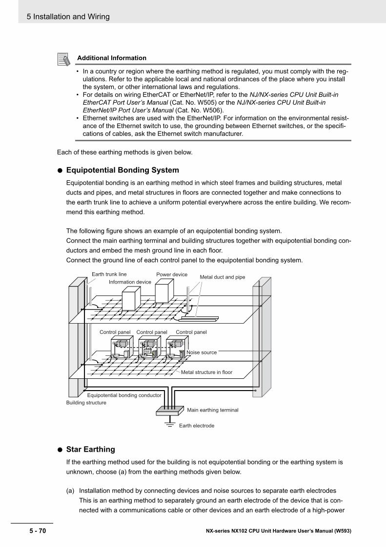
Additional Information
• In a country or region where the earthing method is regulated, you must comply with the reg-ulations. Refer to the applicable local and national ordinances of the place where you installthe system, or other international laws and regulations.
• For details on wiring EtherCAT or EtherNet/IP, refer to the NJ/NX-series CPU Unit Built-inEtherCAT Port User’s Manual (Cat. No. W505) or the NJ/NX-series CPU Unit Built-inEtherNet/IP Port User’s Manual (Cat. No. W506).
• Ethernet switches are used with the EtherNet/IP. For information on the environmental resist-ance of the Ethernet switch to use, the grounding between Ethernet switches, or the specifi-cations of cables, ask the Ethernet switch manufacturer.
Each of these earthing methods is given below.
l Equipotential Bonding SystemEquipotential bonding is an earthing method in which steel frames and building structures, metalducts and pipes, and metal structures in floors are connected together and make connections tothe earth trunk line to achieve a uniform potential everywhere across the entire building. We recom-mend this earthing method.
The following figure shows an example of an equipotential bonding system.Connect the main earthing terminal and building structures together with equipotential bonding con-ductors and embed the mesh ground line in each floor.Connect the ground line of each control panel to the equipotential bonding system.
Information device
Power deviceMetal duct and pipe
Building structure
Equipotential bonding conductor
Main earthing terminal
Earth electrode
Metal structure in floor
Earth trunk line
Control panel
Hub
Control panel Control panel
Noise source
l Star EarthingIf the earthing method used for the building is not equipotential bonding or the earthing system isunknown, choose (a) from the earthing methods given below.
(a) Installation method by connecting devices and noise sources to separate earth electrodesThis is an earthing method to separately ground an earth electrode of the device that is con-nected with a communications cable or other devices and an earth electrode of a high-power
5 Installation and Wiring
5 - 70 NX-series NX102 CPU Unit Hardware User’s Manual (W593)
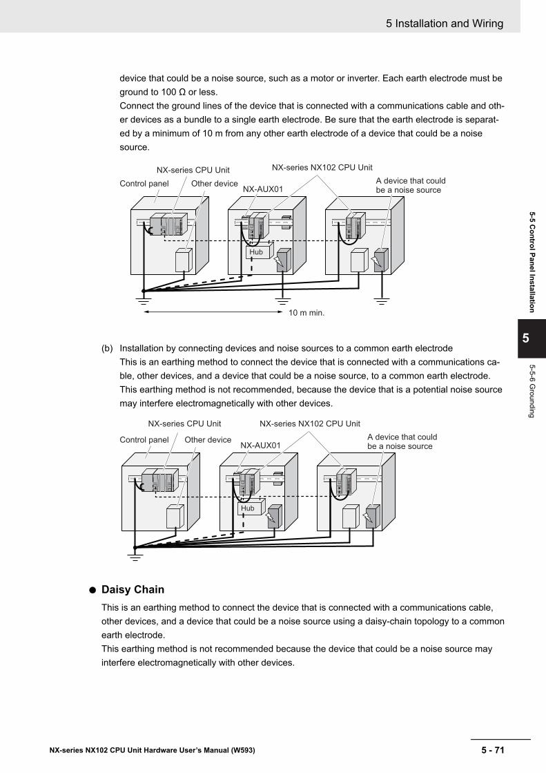
device that could be a noise source, such as a motor or inverter. Each earth electrode must beground to 100 Ω or less.Connect the ground lines of the device that is connected with a communications cable and oth-er devices as a bundle to a single earth electrode. Be sure that the earth electrode is separat-ed by a minimum of 10 m from any other earth electrode of a device that could be a noisesource.
Hub
NX-AUX01
10 m min.
A device that could be a noise source
NX-series CPU Unit
Control panel Other device
NX-series NX102 CPU Unit
(b) Installation by connecting devices and noise sources to a common earth electrodeThis is an earthing method to connect the device that is connected with a communications ca-ble, other devices, and a device that could be a noise source, to a common earth electrode.This earthing method is not recommended, because the device that is a potential noise sourcemay interfere electromagnetically with other devices.
Hub
NX-AUX01A device that could be a noise source
NX-series CPU Unit
Control panel Other device
NX-series NX102 CPU Unit
l Daisy ChainThis is an earthing method to connect the device that is connected with a communications cable,other devices, and a device that could be a noise source using a daisy-chain topology to a commonearth electrode.This earthing method is not recommended because the device that could be a noise source mayinterfere electromagnetically with other devices.
5 Installation and Wiring
5 - 71NX-series NX102 CPU Unit Hardware User’s Manual (W593)
5-5 Control Panel Installation
5
5-5-6 Grounding
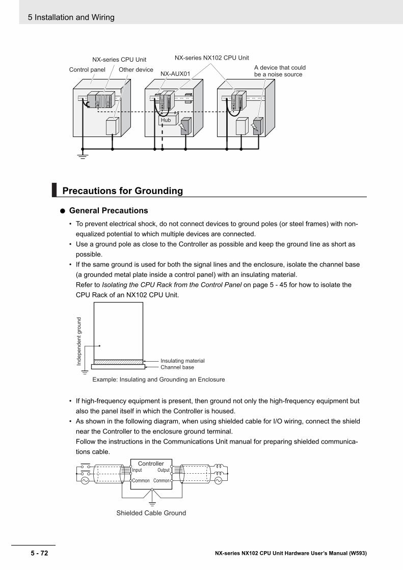
Hub
NX-AUX01A device that could be a noise source
NX-series CPU Unit
Control panel Other device
NX-series NX102 CPU Unit
Precautions for Grounding
l General Precautions• To prevent electrical shock, do not connect devices to ground poles (or steel frames) with non-
equalized potential to which multiple devices are connected.• Use a ground pole as close to the Controller as possible and keep the ground line as short as
possible.• If the same ground is used for both the signal lines and the enclosure, isolate the channel base
(a grounded metal plate inside a control panel) with an insulating material.Refer to Isolating the CPU Rack from the Control Panel on page 5 - 45 for how to isolate theCPU Rack of an NX102 CPU Unit.
Example: Insulating and Grounding an Enclosure
Independent gro
und
Insulating material
Channel base
• If high-frequency equipment is present, then ground not only the high-frequency equipment butalso the panel itself in which the Controller is housed.
• As shown in the following diagram, when using shielded cable for I/O wiring, connect the shieldnear the Controller to the enclosure ground terminal.Follow the instructions in the Communications Unit manual for preparing shielded communica-tions cable.
Shielded Cable Ground
ControllerOutput
Common
Input
Common
5 Installation and Wiring
5 - 72 NX-series NX102 CPU Unit Hardware User’s Manual (W593)
l Controller Ground TerminalsThe Controller has the following ground terminal.
Grounding type Symbol ConnectionFunctionalGrounding
Ground this terminal when power supply noise causes malfunctioning.
When the functional ground terminal is correctly grounded, it is generally effective in suppressingpower supply common noise. Occasionally, however, grounding this terminal will result in pickingup more noise, so be careful when using it.
5 Installation and Wiring
5 - 73NX-series NX102 CPU Unit Hardware User’s Manual (W593)
5-5 Control Panel Installation
5
5-5-6 Grounding

5 Installation and Wiring
5 - 74 NX-series NX102 CPU Unit Hardware User’s Manual (W593)
6Troubleshooting
This section describes the overview of the methods for checking errors.
6-1 Overview of Troubleshooting...................................................................... 6 - 2
6 - 1NX-series NX102 CPU Unit Hardware User’s Manual (W593)
6
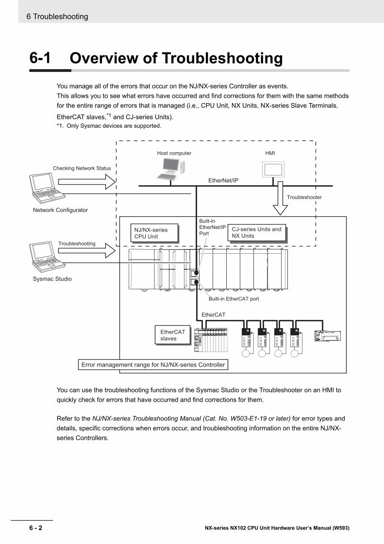
6-1 Overview of TroubleshootingYou manage all of the errors that occur on the NJ/NX-series Controller as events.This allows you to see what errors have occurred and find corrections for them with the same methodsfor the entire range of errors that is managed (i.e., CPU Unit, NX Units, NX-series Slave Terminals,
EtherCAT slaves,*1 and CJ-series Units).*1. Only Sysmac devices are supported.
HMIHost computer
EtherNet/IP
Built-in EtherCAT port
Built-in
EtherNet/IP
Port
EtherCAT
slaves
CJ-series Units and
NX UnitsNJ/NX-series
CPU Unit
Sysmac Studio
Error management range for NJ/NX-series Controller
Troubleshooting
Network Configurator
Checking Network Status
EtherCAT
Troubleshooter
You can use the troubleshooting functions of the Sysmac Studio or the Troubleshooter on an HMI toquickly check for errors that have occurred and find corrections for them.
Refer to the NJ/NX-series Troubleshooting Manual (Cat. No. W503-E1-19 or later) for error types anddetails, specific corrections when errors occur, and troubleshooting information on the entire NJ/NX-series Controllers.
6 Troubleshooting
6 - 2 NX-series NX102 CPU Unit Hardware User’s Manual (W593)
7Inspection and Maintenance
This section describes the required inspections and maintenance. It also describes theservice life and replacement procedure for the Battery.
7-1 Cleaning and Maintenance.......................................................................... 7 - 27-1-1 Cleaning........................................................................................................ 7 - 27-1-2 Periodic Inspections...................................................................................... 7 - 37-1-3 Unit Replacement Precautions ..................................................................... 7 - 4
7-2 Replacing the Battery .................................................................................. 7 - 6
7 - 1NX-series NX102 CPU Unit Hardware User’s Manual (W593)
7
7-1 Cleaning and MaintenanceThis section describes daily maintenance and the cleaning and inspection methods.Daily or periodic inspections are required in order to maintain the NX-series NX102 CPU Unit’s func-tions in peak operating condition.
7-1-1 CleaningPerform the following cleaning procedures periodically to ensure the NX-series CPU Unit is main-tained in the best operating condition. Always turn OFF the power supply to the Controller before per-forming the cleaning procedures.• Wipe off the dust or dirt on the front, top or bottom of the Unit over with a dry, soft cloth when doing
daily cleaning.• If dust or dirt remains even after wiping with a soft, dry cloth, wipe over with a cloth that has been
wet with a sufficiently diluted detergent (2%) and wrung dry.• A smudge may remain on the Unit from gum, vinyl, or tape that was left on for a long time. Remove
the smudge when cleaning.
Precautions for Correct Use
• Never use volatile solvents, such as paint thinner, benzene, or chemical wipes.• Do not touch the connectors.
7 Inspection and Maintenance
7 - 2 NX-series NX102 CPU Unit Hardware User’s Manual (W593)
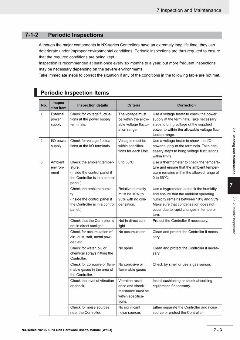
7-1-2 Periodic InspectionsAlthough the major components in NX-series Controllers have an extremely long life time, they candeteriorate under improper environmental conditions. Periodic inspections are thus required to ensurethat the required conditions are being kept.Inspection is recommended at least once every six months to a year, but more frequent inspectionsmay be necessary depending on the severe environments.Take immediate steps to correct the situation if any of the conditions in the following table are not met.
Periodic Inspection Items
No. Inspec-tion item Inspection details Criteria Correction
1 Externalpowersupply
Check for voltage fluctua-tions at the power supplyterminals.
The voltage mustbe within the allow-able voltage fluctu-ation range.
Use a voltage tester to check the powersupply at the terminals. Take necessarysteps to bring voltage of the suppliedpower to within the allowable voltage fluc-tuation range.
2 I/O powersupply
Check for voltage fluctua-tions at the I/O terminals.
Voltages must bewithin specifica-tions for each Unit.
Use a voltage tester to check the I/Opower supply at the terminals. Take nec-essary steps to bring voltage fluctuationswithin limits.
3 Ambientenviron-ment
Check the ambient temper-ature.(Inside the control panel ifthe Controller is in a controlpanel.)
0 to 55°C Use a thermometer to check the tempera-ture and ensure that the ambient temper-ature remains within the allowed range of0 to 55°C.
Check the ambient humidi-ty.(Inside the control panel ifthe Controller is in a controlpanel.)
Relative humiditymust be 10% to95% with no con-densation.
Use a hygrometer to check the humidityand ensure that the ambient operatinghumidity remains between 10% and 95%.Make sure that condensation does notoccur due to rapid changes in tempera-ture.
Check that the Controller isnot in direct sunlight.
Not in direct sun-light
Protect the Controller if necessary.
Check for accumulation ofdirt, dust, salt, metal pow-der, etc.
No accumulation Clean and protect the Controller if neces-sary.
Check for water, oil, orchemical sprays hitting theController.
No spray Clean and protect the Controller if neces-sary.
Check for corrosive or flam-mable gases in the area ofthe Controller.
No corrosive orflammable gases
Check by smell or use a gas sensor.
Check the level of vibrationor shock.
Vibration resist-ance and shockresistance must bewithin specifica-tions.
Install cushioning or shock absorbingequipment if necessary.
Check for noise sourcesnear the Controller.
No significantnoise sources
Either separate the Controller and noisesource or protect the Controller.
7 Inspection and Maintenance
7 - 3NX-series NX102 CPU Unit Hardware User’s Manual (W593)
7-1 Cleaning and M
aintenance
7
7-1-2 Periodic Inspections
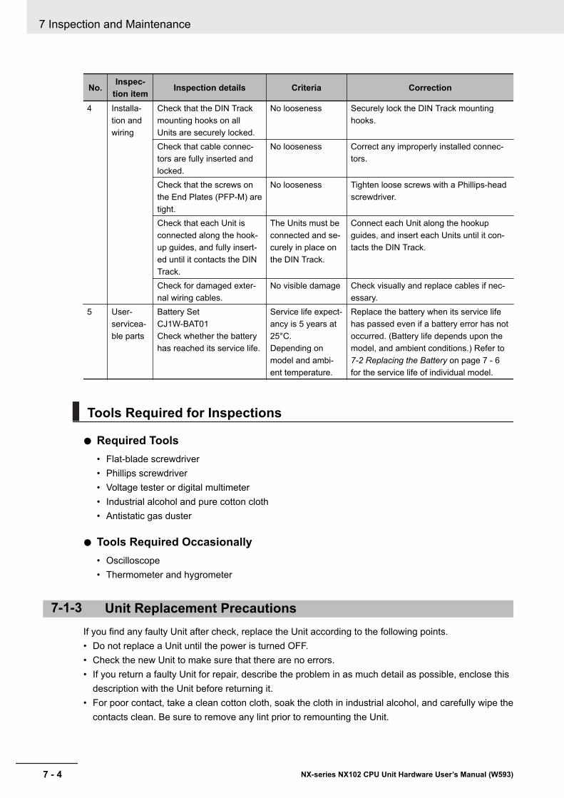
No. Inspec-tion item Inspection details Criteria Correction
4 Installa-tion andwiring
Check that the DIN Trackmounting hooks on allUnits are securely locked.
No looseness Securely lock the DIN Track mountinghooks.
Check that cable connec-tors are fully inserted andlocked.
No looseness Correct any improperly installed connec-tors.
Check that the screws onthe End Plates (PFP-M) aretight.
No looseness Tighten loose screws with a Phillips-headscrewdriver.
Check that each Unit isconnected along the hook-up guides, and fully insert-ed until it contacts the DINTrack.
The Units must beconnected and se-curely in place onthe DIN Track.
Connect each Unit along the hookupguides, and insert each Units until it con-tacts the DIN Track.
Check for damaged exter-nal wiring cables.
No visible damage Check visually and replace cables if nec-essary.
5 User-servicea-ble parts
Battery SetCJ1W-BAT01Check whether the batteryhas reached its service life.
Service life expect-ancy is 5 years at25°C.Depending onmodel and ambi-ent temperature.
Replace the battery when its service lifehas passed even if a battery error has notoccurred. (Battery life depends upon themodel, and ambient conditions.) Refer to 7-2 Replacing the Battery on page 7 - 6for the service life of individual model.
Tools Required for Inspections
l Required Tools• Flat-blade screwdriver• Phillips screwdriver• Voltage tester or digital multimeter• Industrial alcohol and pure cotton cloth• Antistatic gas duster
l Tools Required Occasionally• Oscilloscope• Thermometer and hygrometer
7-1-3 Unit Replacement PrecautionsIf you find any faulty Unit after check, replace the Unit according to the following points.• Do not replace a Unit until the power is turned OFF.• Check the new Unit to make sure that there are no errors.• If you return a faulty Unit for repair, describe the problem in as much detail as possible, enclose this
description with the Unit before returning it.• For poor contact, take a clean cotton cloth, soak the cloth in industrial alcohol, and carefully wipe the
contacts clean. Be sure to remove any lint prior to remounting the Unit.
7 Inspection and Maintenance
7 - 4 NX-series NX102 CPU Unit Hardware User’s Manual (W593)
Precautions for Safe Use
• Make sure that the required data, including the user program, configurations, settings andvariables is transferred to a CPU Unit that was replaced and to externally connected devicesbefore restarting operation. Be sure to include the tag data link settings and routing tables,which are stored in the CPU Unit.
• The absolute encoder home offsets are backed up in the CPU Unit as absolute encoder infor-mation. When you change the combination of the CPU Unit and Servomotor, e.g., when youadd or replace a Servomotor, define the absolute encoder home again.
Precautions for Correct Use
If you replace a slave or Unit, refer to operation manual for the slave or Unit for information onthe data required for individual slaves or Units and redo the necessary settings.
If you use the OPC UA server function with an NX102-££££ and an NJ501-1£00, refer to theNJ/NX-series CPU Unit OPC UA User's Manual (Cat. No. W588) for the description of how to replaceCPU Units.
7 Inspection and Maintenance
7 - 5NX-series NX102 CPU Unit Hardware User’s Manual (W593)
7-1 Cleaning and M
aintenance
7
7-1-3 Unit R
eplacement Precautions
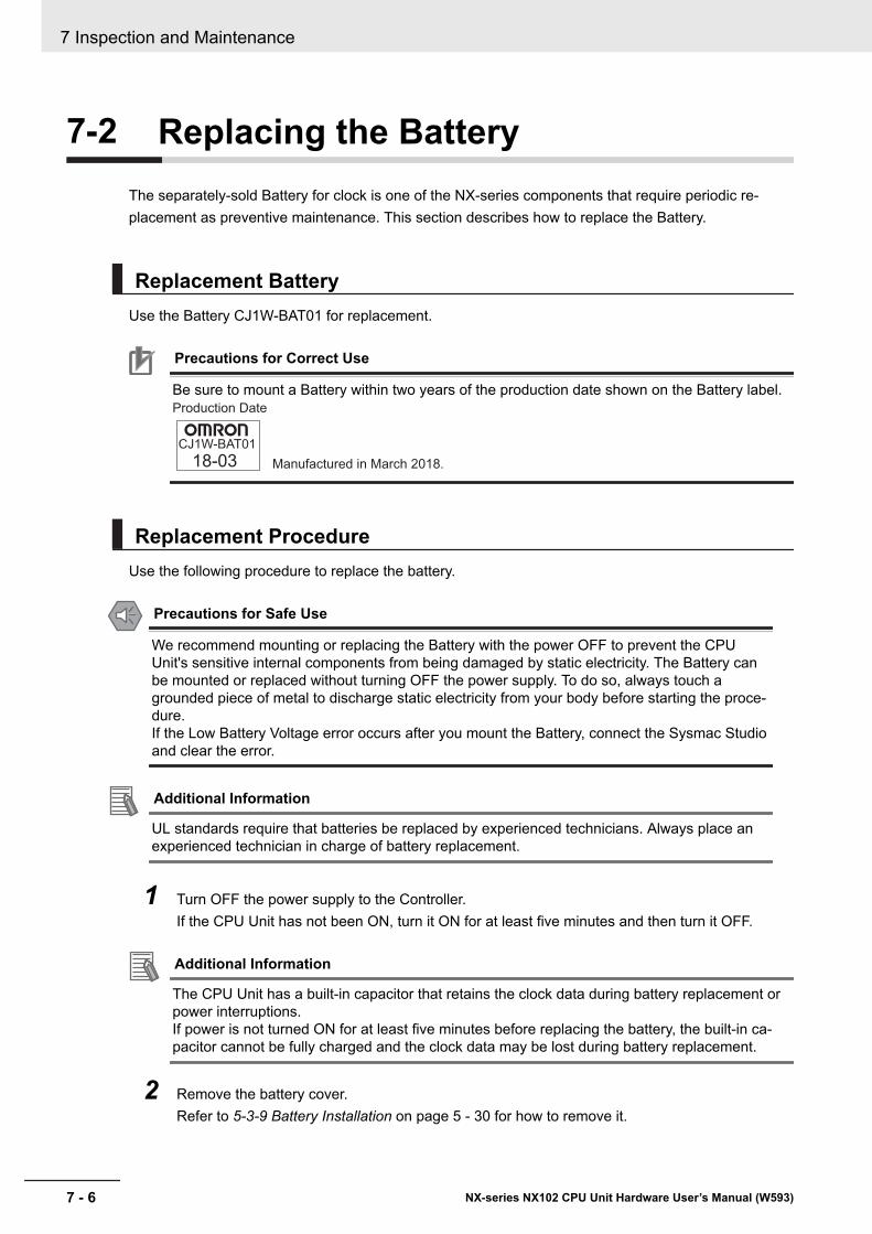
7-2 Replacing the BatteryThe separately-sold Battery for clock is one of the NX-series components that require periodic re-placement as preventive maintenance. This section describes how to replace the Battery.
Replacement BatteryUse the Battery CJ1W-BAT01 for replacement.
Precautions for Correct Use
Be sure to mount a Battery within two years of the production date shown on the Battery label.
CJ1W-BAT01
18-03 Manufactured in March 2018.
Production Date
Replacement ProcedureUse the following procedure to replace the battery.
Precautions for Safe Use
We recommend mounting or replacing the Battery with the power OFF to prevent the CPUUnit's sensitive internal components from being damaged by static electricity. The Battery canbe mounted or replaced without turning OFF the power supply. To do so, always touch agrounded piece of metal to discharge static electricity from your body before starting the proce-dure.If the Low Battery Voltage error occurs after you mount the Battery, connect the Sysmac Studioand clear the error.
Additional Information
UL standards require that batteries be replaced by experienced technicians. Always place anexperienced technician in charge of battery replacement.
1 Turn OFF the power supply to the Controller.If the CPU Unit has not been ON, turn it ON for at least five minutes and then turn it OFF.
Additional Information
The CPU Unit has a built-in capacitor that retains the clock data during battery replacement orpower interruptions.If power is not turned ON for at least five minutes before replacing the battery, the built-in ca-pacitor cannot be fully charged and the clock data may be lost during battery replacement.
2 Remove the battery cover.Refer to 5-3-9 Battery Installation on page 5 - 30 for how to remove it.
7 Inspection and Maintenance
7 - 6 NX-series NX102 CPU Unit Hardware User’s Manual (W593)
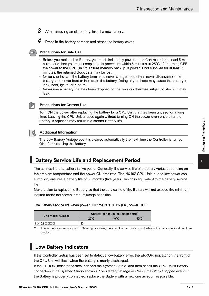
3 After removing an old battery, install a new battery.
4 Press in the battery harness and attach the battery cover.
Precautions for Safe Use
• Before you replace the Battery, you must first supply power to the Controller for at least 5 mi-nutes, and then you must complete this procedure within 5 minutes at 25°C after turning OFFthe power to the CPU Unit to ensure memory backup. If power is not supplied for at least 5minutes, the retained clock data may be lost.
• Never short-circuit the battery terminals; never charge the battery; never disassemble thebattery; and never heat or incinerate the battery. Doing any of these may cause the battery toleak, heat, ignite, or rupture.
• Never use a battery that has been dropped on the floor or otherwise subject to shock. It mayleak.
Precautions for Correct Use
Turn ON the power after replacing the battery for a CPU Unit that has been unused for a longtime. Leaving the CPU Unit unused again without turning ON the power even once after theBattery is replaced may result in a shorter Battery life.
Additional Information
The Low Battery Voltage event is cleared automatically the next time the Controller is turnedON after replacing the Battery.
Battery Service Life and Replacement PeriodThe service life of a battery is five years. Generally, the service life of a battery varies depending onthe ambient temperature and the power ON time rate. The NX102 CPU Unit, due to low power con-sumption, ensures a battery life of 60 months (five years), which is equivalent to the battery servicelife.Make a plan to replace the Battery so that the service life of the Battery will not exceed the minimumlifetime under the normal product usage condition.
The Battery service life when power ON time rate is 0% (i.e., power OFF)
Unit model number Approx. minimum lifetime [month]*1
25°C 40°C 55°CNX102-££££ 60
*1. This is the life expectancy which Omron guarantees, based on the calculation worst value of the part's specification of theproduct.
Low Battery IndicatorsIf the Controller Setup has been set to detect a low-battery error, the ERROR indicator on the front ofthe CPU Unit will flash when the battery is nearly discharged.If the ERROR indicator flashes, connect the Sysmac Studio, and then check the CPU Unit’s Batteryconnection if the Sysmac Studio shows a Low Battery Voltage or Real-Time Clock Stopped event. Ifthe Battery is properly connected, replace the Battery with a new one as soon as possible.
7 Inspection and Maintenance
7 - 7NX-series NX102 CPU Unit Hardware User’s Manual (W593)
7-2 Replacing the B
attery
7
Once a low-battery error has been detected, it will take 5 days (at an ambient temperature of 25°C)before the battery fails if power has been supplied at least once a day.Clock data and variables that are retained during power interruptions can be retained by ensuring thatthe CPU Unit power is not turned OFF until the Battery has been replaced.
Additional Information
The Battery will lose its charge faster at high ambient temperatures.
7 Inspection and Maintenance
7 - 8 NX-series NX102 CPU Unit Hardware User’s Manual (W593)
AAppendices
The appendices provide the general specifications of the CPU Unit and Unit dimen-sions.
A-1 Specifications.............................................................................................. A - 2A-2 Dimensions.................................................................................................. A - 3
A-2-1 NX-series NX102 CPU Unit ..........................................................................A - 3A-2-2 End Cover.....................................................................................................A - 3A-2-3 SD Memory Card ..........................................................................................A - 4
A-3 List of Terminal Block Models.................................................................... A - 5A-3-1 Model Notation..............................................................................................A - 5A-3-2 List of Terminal Block Models .......................................................................A - 5
A-4 Version Information .................................................................................... A - 7A-4-1 Relationship between Unit Versions of CPU Units and Sysmac Stu-
dio Versions...................................................................................................A - 7A-4-2 Functions That Were Added or Changed for Each Unit Version ..................A - 7
A-5 Support Functions of the CPU Units and Restrictions on the CPUUnit ................................................................................................................ A - 8
A - 1NX-series NX102 CPU Unit Hardware User’s Manual (W593)
A
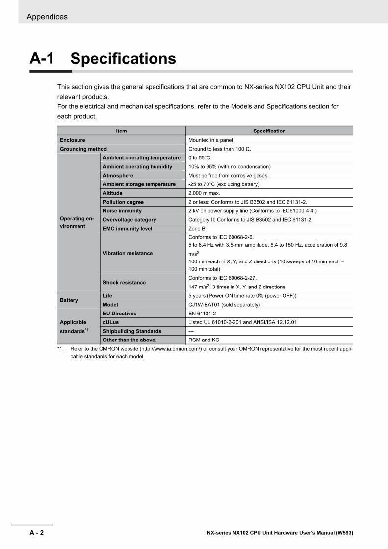
A-1 SpecificationsThis section gives the general specifications that are common to NX-series NX102 CPU Unit and theirrelevant products.For the electrical and mechanical specifications, refer to the Models and Specifications section foreach product.
Item SpecificationEnclosure Mounted in a panelGrounding method Ground to less than 100 Ω.
Operating en-vironment
Ambient operating temperature 0 to 55°CAmbient operating humidity 10% to 95% (with no condensation)Atmosphere Must be free from corrosive gases.Ambient storage temperature -25 to 70°C (excluding battery)Altitude 2,000 m max.Pollution degree 2 or less: Conforms to JIS B3502 and IEC 61131-2.Noise immunity 2 kV on power supply line (Conforms to IEC61000-4-4.)Overvoltage category Category II: Conforms to JIS B3502 and IEC 61131-2.EMC immunity level Zone B
Vibration resistance
Conforms to IEC 60068-2-6.5 to 8.4 Hz with 3.5-mm amplitude, 8.4 to 150 Hz, acceleration of 9.8
m/s2
100 min each in X, Y, and Z directions (10 sweeps of 10 min each =100 min total)
Shock resistanceConforms to IEC 60068-2-27.
147 m/s2, 3 times in X, Y, and Z directions
BatteryLife 5 years (Power ON time rate 0% (power OFF))Model CJ1W-BAT01 (sold separately)
Applicablestandards*1
EU Directives EN 61131-2cULus Listed UL 61010-2-201 and ANSI/ISA 12.12.01Shipbuilding Standards ---Other than the above. RCM and KC
*1. Refer to the OMRON website (http://www.ia.omron.com/) or consult your OMRON representative for the most recent appli-cable standards for each model.
Appendices
A - 2 NX-series NX102 CPU Unit Hardware User’s Manual (W593)
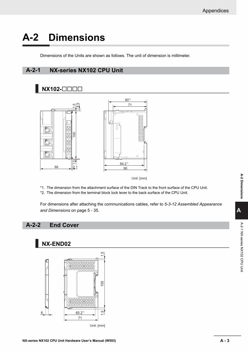
A-2 DimensionsDimensions of the Units are shown as follows. The unit of dimension is millimeter.
A-2-1 NX-series NX102 CPU Unit
NX102-££££
66 2.1
1.5
4.5
100
84.2*1
80*2
71
90
1.5
Unit: [mm]
*1. The dimension from the attachment surface of the DIN Track to the front surface of the CPU Unit.*2. The dimension from the terminal block lock lever to the back surface of the CPU Unit.
For dimensions after attaching the communications cables, refer to 5-3-12 Assembled Appearanceand Dimensions on page 5 - 35.
A-2-2 End Cover
NX-END02
Unit: [mm]
65.2*1
71
6
100
1.5
1.5
Appendices
A - 3NX-series NX102 CPU Unit Hardware User’s Manual (W593)
A-2 D
imensions
A
A-2-1 NX-series N
X102 CPU
Unit
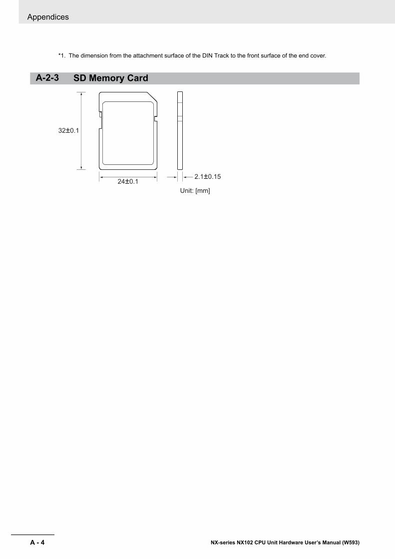
*1. The dimension from the attachment surface of the DIN Track to the front surface of the end cover.
A-2-3 SD Memory Card
2.1±0.15
32±0.1
24±0.1
Unit: [mm]
Appendices
A - 4 NX-series NX102 CPU Unit Hardware User’s Manual (W593)
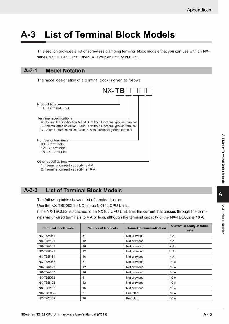
A-3 List of Terminal Block ModelsThis section provides a list of screwless clamping terminal block models that you can use with an NX-series NX102 CPU Unit, EtherCAT Coupler Unit, or NX Unit.
A-3-1 Model NotationThe model designation of a terminal block is given as follows.
NX-TB££££
Product type TB:
Terminal specifications A: Column letter indication A and B, without functional ground terminal B: Column letter indication C and D, without functional ground terminal C: Column letter indication A and B, with functional ground terminal
Number of terminals 08: 8 terminals 12: 12 terminals 16: 16 terminals
Other specifications 1: Terminal current capacity is 4 A. 2: Terminal current capacity is 10 A.
Terminal block
A-3-2 List of Terminal Block ModelsThe following table shows a list of terminal blocks.Use the NX-TBC082 for NX-series NX102 CPU Units.If the NX-TBC082 is attached to an NX102 CPU Unit, limit the current that passes through the termi-nals via unwired terminals to 4 A or less, although the terminal capacity of the NX-TBC082 is 10 A.
Terminal block model Number of terminals Ground terminal indicationCurrent capacity of termi-
nalsNX-TBA081 8 Not provided 4 ANX-TBA121 12 Not provided 4 ANX-TBA161 16 Not provided 4 ANX-TBB121 12 Not provided 4 ANX-TBB161 16 Not provided 4 ANX-TBA082 8 Not provided 10 ANX-TBA122 12 Not provided 10 ANX-TBA162 16 Not provided 10 ANX-TBB082 8 Not provided 10 ANX-TBB122 12 Not provided 10 ANX-TBB162 16 Not provided 10 ANX-TBC082 8 Provided 10 ANX-TBC162 16 Provided 10 A
Appendices
A - 5NX-series NX102 CPU Unit Hardware User’s Manual (W593)
A-3 List of Term
inal Block M
odels
A
A-3-1 Model N
otation

Note When you purchase a terminal block, purchase an NX-TB£££2.
Appendices
A - 6 NX-series NX102 CPU Unit Hardware User’s Manual (W593)
A-4 Version InformationThis section describes the relationship between the unit versions of the NX-series NX102 CPU Unitand the Sysmac Studio versions, and the functions that are supported for each unit version.Refer to the A-5 Support Functions of the CPU Units and Restrictions on the CPU Unit on pageA - 8 for information on NX Units that can be connected to the CPU Unit.
A-4-1 Relationship between Unit Versions of CPU Units and SysmacStudio Versions
This section describes how the unit versions of NX-series NX102 CPU Unit correspond to SysmacStudio versions.
Unit Versions and Corresponding Sysmac Studio VersionsThis following table gives the relationship between the unit versions of NX-series NX102 CPU Unitsand the corresponding Sysmac Studio versions.
Unit version of CPU Unit Corresponding version of Sysmac Studio
Ver. 1.30*1 Ver. 1.23
*1. There is no NX102 CPU Unit with unit version 1.29 or earlier.
A-4-2 Functions That Were Added or Changed for Each Unit VersionThis section describes the functions that were added or changed for each unit version of NX-seriesNX1P2 CPU Unit.
l Additions and Changes to Basic Instructions and Motion Control Instruc-tionsThe basic instructions and motion control instructions that you can use have increased or changedfor the new unit version of the CPU Unit.For details, refer to the NJ/NX-series Instructions Reference Manual (Cat. No. W502) and NJ/NX-series Motion Control Instructions Reference Manual (Cat. No. W508).
l Additions and Changes to Controller EventsThe events that can occur have increased or changed for the new unit version of the CPU Unit.There are also changes in the recovery methods to use when some errors occur.For details, refer to the NJ/NX-series Troubleshooting Manual (Cat. No. W503).
l Additions and Changes to System-defined VariablesThe system-defined variables that you can use have increased or changed for the new unit versionof the CPU Unit.Refer to the NJ/NX-series CPU Unit Software User's Manual (Cat. No. W501) for details.
Appendices
A - 7NX-series NX102 CPU Unit Hardware User’s Manual (W593)
A-4 Version Inform
ation
A
A-4-1 Relationship betw
een Unit Versions of C
PU U
nits and Sysmac
Studio Versions
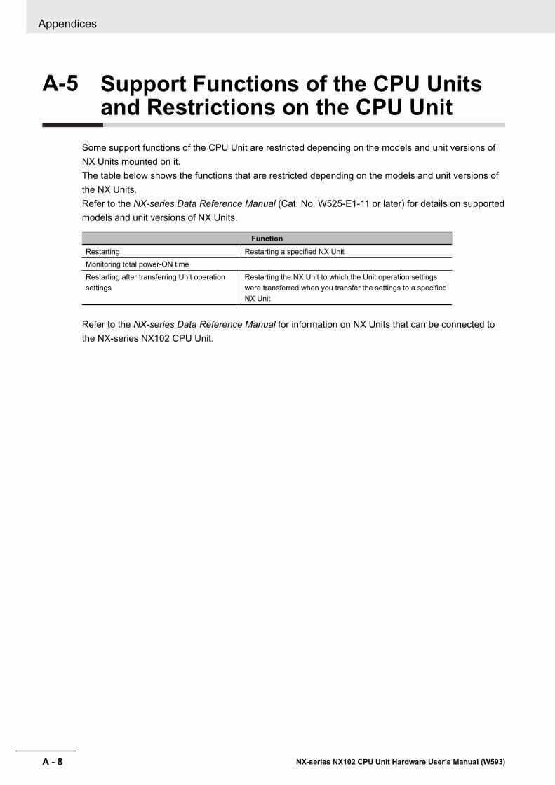
A-5 Support Functions of the CPU Unitsand Restrictions on the CPU Unit
Some support functions of the CPU Unit are restricted depending on the models and unit versions ofNX Units mounted on it.The table below shows the functions that are restricted depending on the models and unit versions ofthe NX Units.Refer to the NX-series Data Reference Manual (Cat. No. W525-E1-11 or later) for details on supportedmodels and unit versions of NX Units.
FunctionRestarting Restarting a specified NX UnitMonitoring total power-ON timeRestarting after transferring Unit operationsettings
Restarting the NX Unit to which the Unit operation settingswere transferred when you transfer the settings to a specifiedNX Unit
Refer to the NX-series Data Reference Manual for information on NX Units that can be connected tothe NX-series NX102 CPU Unit.
Appendices
A - 8 NX-series NX102 CPU Unit Hardware User’s Manual (W593)

IIndex
I - 1NX-series NX102 CPU Unit Hardware User’s Manual (W593)
I
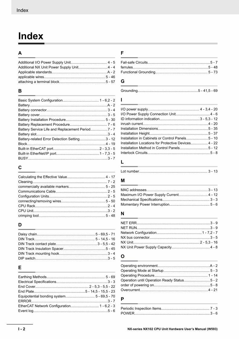
IndexA
Additional I/O Power Supply Unit.................................... 4 - 5Additional NX Unit Power Supply Unit.............................4 - 4Applicable standards.......................................................A - 2applicable wires............................................................. 5 - 46attaching a terminal block..............................................5 - 57
B
Basic System Configuration.................................... 1 - 6,2 - 2Battery.............................................................................A - 2Battery connector............................................................ 3 - 4Battery cover................................................................... 3 - 5Battery Installation Procedure....................................... 5 - 30Battery Replacement Procedure..................................... 7 - 6Battery Service Life and Replacement Period.................7 - 7Battery slot.......................................................................3 - 4Battery-related Error Detection Setting..........................3 - 12Block..............................................................................4 - 19Built-in EtherCAT port..............................................2 - 3,3 - 5Built-in EtherNet/IP port...........................................1 - 7,3 - 5BUSY...............................................................................3 - 7
C
Calculating the Effective Value...................................... 4 - 17Cleaning.......................................................................... 7 - 2commercially available markers.................................... 5 - 25Communications Cable................................................... 2 - 5Configuration Units.......................................................... 2 - 5connecting/removing wires............................................ 5 - 50CPU Rack........................................................................2 - 4CPU Unit..........................................................................3 - 2crimping tool.................................................................. 5 - 48
D
Daisy chain..........................................................5 - 69,5 - 71DIN Track............................................................ 5 - 14,5 - 16DIN Track contact plate......................................... 3 - 5,5 - 42DIN Track Insulation Spacer..........................................5 - 45DIN Track mounting hook................................................ 3 - 4DIP switch........................................................................3 - 5
E
Earthing Methods.......................................................... 5 - 69Electrical Specifications...................................................3 - 3End Cover..................................................... 2 - 5,3 - 5,5 - 22End Plate...................................................5 - 14,5 - 15,5 - 23Equipotential bonding system............................. 5 - 69,5 - 70ERROR............................................................................3 - 7EtherCAT Network Configuration............................ 1 - 6,2 - 3Event log..........................................................................5 - 6
F
Fail-safe Circuits..............................................................5 - 7ferrules...........................................................................5 - 48Functional Grounding.................................................... 5 - 73
G
Grounding............................................................5 - 41,5 - 69
I
I/O power supply................................................... 4 - 3,4 - 20I/O Power Supply Connection Unit.................................. 4 - 6ID information indication........................................3 - 5,3 - 12inrush current.................................................................4 - 20Installation Dimensions..................................................5 - 35Installation Height.......................................................... 5 - 37Installation in Cabinets or Control Panels......................5 - 10Installation Locations for Protective Devices................. 4 - 22Installation Method in Control Panels............................ 5 - 12Interlock Circuits.............................................................. 5 - 8
L
Lot number.................................................................... 3 - 13
M
MAC addresses............................................................. 3 - 13Maximum I/O Power Supply Current............................. 4 - 12Mechanical Specifications............................................... 3 - 3Momentary Power Interruption........................................ 5 - 6
N
NET ERR.........................................................................3 - 9NET RUN.........................................................................3 - 9Network Configuration.............................................1 - 7,2 - 7NX bus connector............................................................ 3 - 5NX Unit.................................................................. 2 - 5,3 - 16NX Unit Power Supply Capacity...................................... 4 - 8
O
Operating environment....................................................A - 2Operating Mode at Startup.............................................. 5 - 3Operating Procedure..................................................... 1 - 14Operation until Operation Ready Status..........................5 - 2order of powering on........................................................5 - 8Overcurrent....................................................................4 - 21
P
Periodic Inspection Items................................................ 7 - 3POWER........................................................................... 3 - 6
Index
I - 2 NX-series NX102 CPU Unit Hardware User’s Manual (W593)
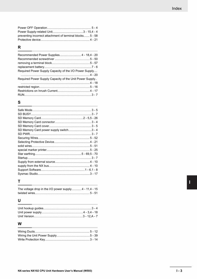
Power OFF Operation..................................................... 5 - 4Power Supply-related Unit.....................................3 - 15,4 - 4preventing incorrect attachment of terminal blocks....... 5 - 58Protective device........................................................... 4 - 21
R
Recommended Power Supplies.......................... 4 - 18,4 - 20Recommended screwdriver ..........................................5 - 50removing a terminal block..............................................5 - 57replacement battery.........................................................7 - 6Required Power Supply Capacity of the I/O Power Supply....
................................................................................... 4 - 20Required Power Supply Capacity of the Unit Power Supply..
................................................................................... 4 - 18restricted region.............................................................5 - 16Restrictions on Inrush Current.......................................4 - 17RUN.................................................................................3 - 7
S
Safe Mode....................................................................... 3 - 5SD BUSY.........................................................................3 - 7SD Memory Card...................................................2 - 5,5 - 26SD Memory Card connector............................................ 3 - 4SD Memory Card cover................................................... 3 - 5SD Memory Card power supply switch............................3 - 4SD PWR.......................................................................... 3 - 7Securing Wires.............................................................. 5 - 52Selecting Protective Device...........................................4 - 21solid wires......................................................................5 - 51special marker printer.................................................... 5 - 25Star earthing........................................................5 - 69,5 - 70Startup............................................................................. 3 - 7Supply from external source..........................................4 - 10supply from the NX bus................................................. 4 - 10Support Software.....................................................1 - 6,1 - 8Sysmac Studio...............................................................3 - 17
T
The voltage drop in the I/O power supply............4 - 11,4 - 15twisted wires.................................................................. 5 - 51
U
Unit hookup guides..........................................................3 - 4Unit power supply..................................................4 - 3,4 - 18Unit Version...........................................................3 - 12,A - 7
W
Wiring Ducts.................................................................. 5 - 12Wiring the Unit Power Supply........................................5 - 39Write Protection Key......................................................3 - 14
Index
I - 3NX-series NX102 CPU Unit Hardware User’s Manual (W593)
I
OMRON CANADA, INC. • HEAD OFFICEToronto, ON, Canada • 416.286.6465 • 866.986.6766 • www.omron247.com
OMRON ELECTRONICS DE MEXICO • HEAD OFFICEMéxico DF • 52.55.59.01.43.00 • 01-800-226-6766 • [email protected]
OMRON ELECTRONICS DE MEXICO • SALES OFFICEApodaca, N.L. • 52.81.11.56.99.20 • 01-800-226-6766 • [email protected]
OMRON ELETRÔNICA DO BRASIL LTDA • HEAD OFFICESão Paulo, SP, Brasil • 55.11.2101.6300 • www.omron.com.br
OMRON ARGENTINA • SALES OFFICECono Sur • 54.11.4783.5300
OMRON CHILE • SALES OFFICESantiago • 56.9.9917.3920
OTHER OMRON LATIN AMERICA SALES54.11.4783.5300
Authorized Distributor:
F204I-E-01 Note: Specifications are subject to change. © 2018 Omron. All Rights Reserved. Printed in U.S.A.
Printed on recycled paper.
OMRON AUTOMATION AMERICAS HEADQUARTERS • Chicago, IL USA • 847.843.7900 • 800.556.6766 • www.omron247.com
OMRON EUROPE B.V. • Wegalaan 67-69, NL-2132 JD, Hoofddorp, The Netherlands. • +31 (0) 23 568 13 00 • www.industrial.omron.eu
Controllers & I/O • Machine Automation Controllers (MAC) • Motion Controllers • Programmable Logic Controllers (PLC) • Temperature Controllers • Remote I/O
Robotics • Industrial Robots • Mobile Robots
Operator Interfaces• Human Machine Interface (HMI)
Motion & Drives• Machine Automation Controllers (MAC) • Motion Controllers • Servo Systems • Frequency Inverters
Vision, Measurement & Identification• Vision Sensors & Systems • Measurement Sensors • Auto Identification Systems
Sensing• Photoelectric Sensors • Fiber-Optic Sensors • Proximity Sensors • Rotary Encoders • Ultrasonic Sensors
Safety • Safety Light Curtains • Safety Laser Scanners • Programmable Safety Systems • Safety Mats and Edges • Safety Door Switches • Emergency Stop Devices • Safety Switches & Operator Controls • Safety Monitoring/Force-guided Relays
Control Components • Power Supplies • Timers • Counters • Programmable Relays • Digital Panel Meters • Monitoring Products
Switches & Relays • Limit Switches • Pushbutton Switches • Electromechanical Relays • Solid State Relays
Software • Programming & Configuration • Runtime


