
Programming Manual
Logix 5000 Controllers Information and Status 1756 ControlLogix, 1756 GuardLogix, 1769 CompactLogix, 1769 Compact GuardLogix, 1789 SoftLogix, 5069 CompactLogix, 5069 Compact GuardLogix, Studio 5000 Logix Emulate
Important user information Read this document and the documents listed in the additional resources section about installation, configuration, and operation of this equipment before you install, configure, operate, or maintain this product. Users are required to familiarize themselves with installation and wiring instructions in addition to requirements of all applicable codes, laws, and standards.
Activities including installation, adjustments, putting into service, use, assembly, disassembly, and maintenance are required to be carried out by suitably trained personnel in accordance with applicable code of practice. If this equipment is used in a manner not specified by the manufacturer, the protection provided by the equipment may be impaired.
In no event will Rockwell Automation, Inc. be responsible or liable for indirect or consequential damages resulting from the use or application of this equipment.
The examples and diagrams in this manual are included solely for illustrative purposes. Because of the many variables and requirements associated with any particular installation, Rockwell Automation, Inc. cannot assume responsibility or liability for actual use based on the examples and diagrams.
No patent liability is assumed by Rockwell Automation, Inc. with respect to use of information, circuits, equipment, or software described in this manual.
Reproduction of the contents of this manual, in whole or in part, without written permission of Rockwell Automation, Inc., is prohibited.
Throughout this manual, when necessary, we use notes to make you aware of safety considerations.
WARNING: Identifies information about practices or circumstances that can cause an explosion in a hazardous environment, which may lead to personal injury or death, property damage, or economic loss.
ATTENTION: Identifies information about practices or circumstances that can lead to personal injury or death, property damage, or economic loss. Attentions help you identify a hazard, avoid a hazard, and recognize the consequence
Important: Identifies information that is critical for successful application and understanding of the product.
Labels may also be on or inside the equipment to provide specific precautions.
SHOCK HAZARD: Labels may be on or inside the equipment, for example, a drive or motor, to alert people that dangerous voltage may be present.
BURN HAZARD: Labels may be on or inside the equipment, for example, a drive or motor, to alert people that surfaces may reach dangerous temperatures.
ARC FLASH HAZARD: Labels may be on or inside the equipment, for example, a motor control center, to alert people to potential Arc Flash. Arc Flash will cause severe injury or death. Wear proper Personal Protective Equipment (PPE). Follow ALL Regulatory requirements for safe work practices and for Personal Protective Equipment (PPE).
Allen-Bradley, Rockwell Software, Rockwell Automation, and TechConnect are trademarks of Rockwell Automation, Inc.
Trademarks not belonging to Rockwell Automation are property of their respective companies.
Rockwell Automation Publication 1756-PM015I-EN-P - February 2018 3
Summary of Changes
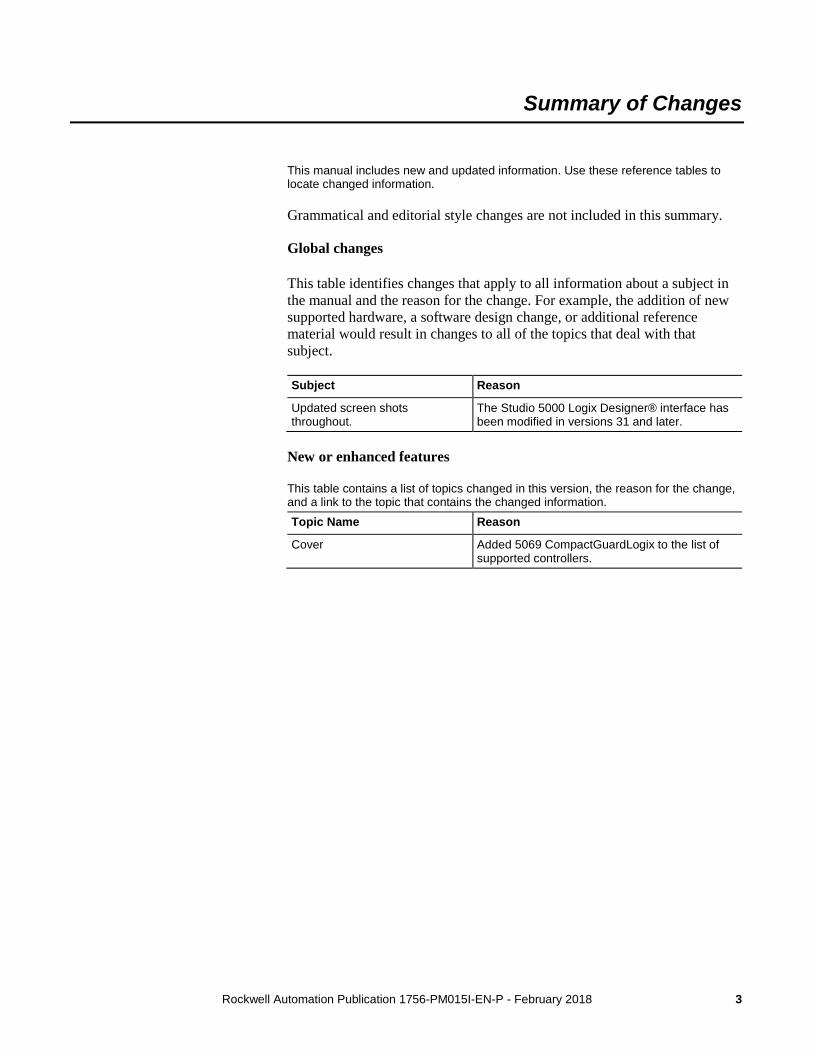
This manual includes new and updated information. Use these reference tables to locate changed information.
Grammatical and editorial style changes are not included in this summary.
Global changes
This table identifies changes that apply to all information about a subject in the manual and the reason for the change. For example, the addition of new supported hardware, a software design change, or additional reference material would result in changes to all of the topics that deal with that subject.
Subject Reason
Updated screen shots throughout.
The Studio 5000 Logix Designer® interface has been modified in versions 31 and later.
New or enhanced features
This table contains a list of topics changed in this version, the reason for the change, and a link to the topic that contains the changed information. Topic Name Reason
Cover Added 5069 CompactGuardLogix to the list of supported controllers.

Rockwell Automation Publication 1756-PM015I-EN-P - February 2018 5
Table of contents
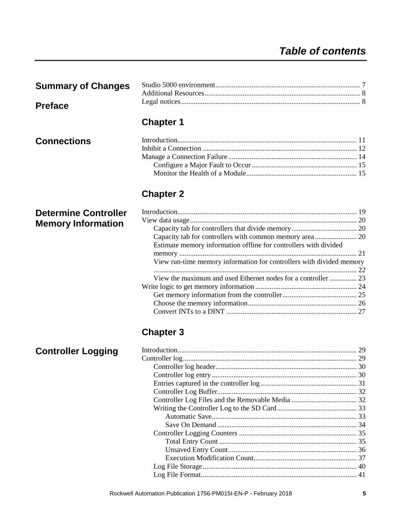
Studio 5000 environment ................................................................................ 7 Additional Resources ...................................................................................... 8 Legal notices ................................................................................................... 8
Chapter 1
Introduction ................................................................................................... 11 Inhibit a Connection ..................................................................................... 12 Manage a Connection Failure ....................................................................... 14
Configure a Major Fault to Occur .......................................................... 15 Monitor the Health of a Module ............................................................. 15
Chapter 2
Introduction ................................................................................................... 19 View data usage ............................................................................................ 20
Capacity tab for controllers that divide memory .................................... 20 Capacity tab for controllers with common memory area ....................... 20 Estimate memory information offline for controllers with divided memory .................................................................................................. 21 View run-time memory information for controllers with divided memory ................................................................................................................ 22 View the maximum and used Ethernet nodes for a controller ............... 23
Write logic to get memory information ........................................................ 24 Get memory information from the controller ......................................... 25 Choose the memory information ............................................................ 26 Convert INTs to a DINT ........................................................................ 27
Chapter 3
Introduction ................................................................................................... 29 Controller log ................................................................................................ 29
Controller log header .............................................................................. 30 Controller log entry ................................................................................ 30 Entries captured in the controller log ..................................................... 31 Controller Log Buffer............................................................................. 32 Controller Log Files and the Removable Media .................................... 32 Writing the Controller Log to the SD Card ............................................ 33
Automatic Save ................................................................................ 33 Save On Demand ............................................................................. 34
Controller Logging Counters ................................................................. 35 Total Entry Count ............................................................................ 35 Unsaved Entry Count ....................................................................... 36 Execution Modification Count......................................................... 37
Log File Storage ..................................................................................... 40 Log File Format ...................................................................................... 41
Summary of Changes
Preface
Connections
Determine Controller Memory Information
Controller Logging
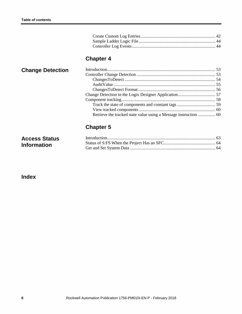
Table of contents
6 Rockwell Automation Publication 1756-PM015I-EN-P - February 2018
Create Custom Log Entries .................................................................... 42 Sample Ladder Logic File ...................................................................... 44 Controller Log Events ............................................................................ 44
Chapter 4
Introduction ................................................................................................... 53 Controller Change Detection ........................................................................ 53
ChangesToDetect ................................................................................... 54 AuditValue ............................................................................................. 55 ChangesToDetect Format ....................................................................... 56
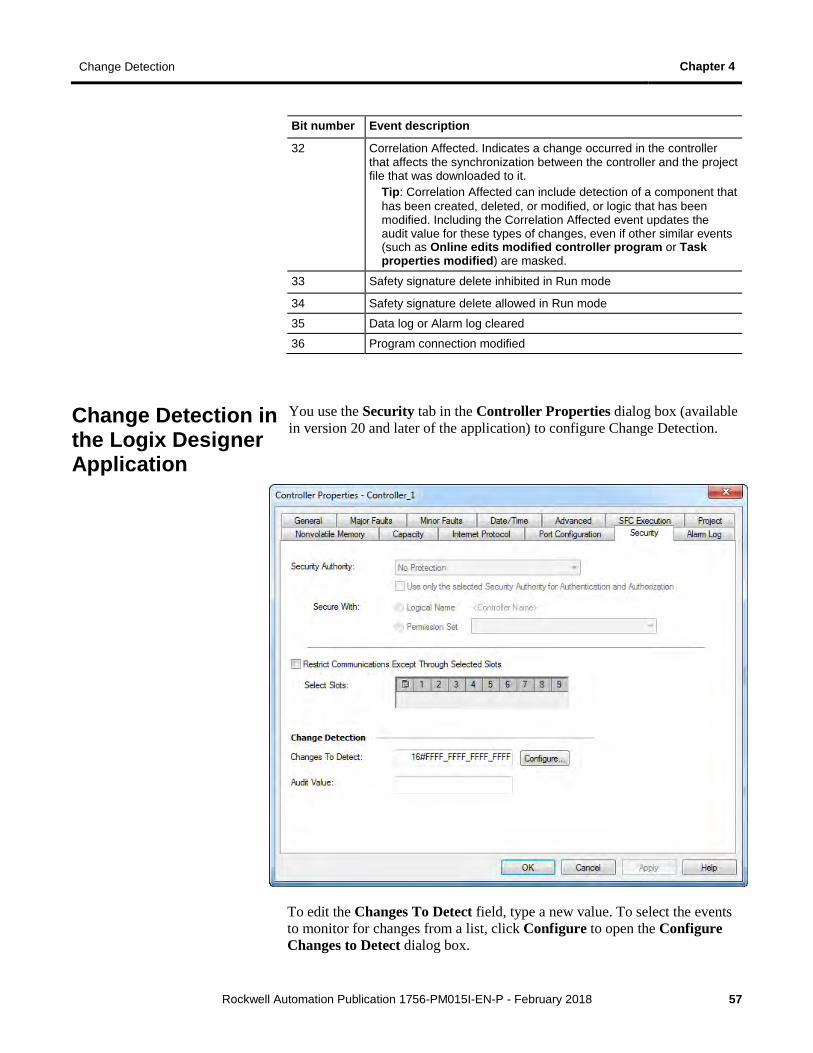
Change Detection in the Logix Designer Application .................................. 57 Component tracking ...................................................................................... 58
Track the state of components and constant tags ................................... 59 View tracked components ...................................................................... 60 Retrieve the tracked state value using a Message instruction ................ 60
Chapter 5
Introduction ................................................................................................... 63 Status of S:FS When the Project Has an SFC ............................................... 64 Get and Set System Data .............................................................................. 64
Change Detection
Access Status Information
Index
Rockwell Automation Publication 1756-PM015I-EN-P - February 2018 7
Preface
This manual describes how Logix 5000 controllers use connections with other devices. This manual also describes status keywords and how to get controller information, such as memory resources. This manual is one of a set of related manuals that show common procedures for programming and operating Logix 5000™ controllers.
For a complete list of common procedures manuals, refer to the Logix 5000 Controllers Common Procedures Programming Manual , publication 1756-PM001 .
• The term Logix 5000 controller refers to any controller that is based on the Logix 5000 operating system.
The Studio 5000 Automation Engineering & Design Environment® combines engineering and design elements into a common environment. The first element is the Studio 5000 Logix Designer® application. The Logix Designer application is the rebranding of RSLogix 5000® software and will continue to be the product to program Logix 5000™ controllers for discrete, process, batch, motion, safety, and drive-based solutions.
The Studio 5000® environment is the foundation for the future of Rockwell Automation® engineering design tools and capabilities. The Studio 5000 environment is the one place for design engineers to develop all elements of their control system.
Studio 5000 environment
Preface
8 Rockwell Automation Publication 1756-PM015I-EN-P - February 2018
These documents contain additional information concerning related Rockwell Automation products.
Resource Description
Industrial Automation Wiring and Grounding Guidelines, publication,1770-4.1 .
Provides general guidelines for installing a Rockwell Automation industrial system.
Product Certifications website, http://www.ab.com
Provides declarations of conformity, certificates, and other certification details.
You can view or download publications at http://www.rockwellautomation.com/literature . To order paper copies of technical documentation, contact your local Rockwell Automation distributor or sales representative.
Copyright notice
Copyright © 2018 Rockwell Automation Technologies, Inc. All Rights Reserved. Printed in USA.
This document and any accompanying Rockwell Software products are copyrighted by Rockwell Automation Technologies, Inc. Any reproduction and/or distribution without prior written consent from Rockwell Automation Technologies, Inc. is strictly prohibited. Please refer to the license agreement for details.
End User License Agreement (EULA)
You can view the Rockwell Automation End-User License Agreement ("EULA") by opening the License.rtf file located in your product's install folder on your hard drive.
Other Licenses
The software included in this product contains copyrighted software that is licensed under one or more open source licenses. Copies of those licenses are included with the software. Corresponding Source code for open source packages included in this product can be located at their respective web site(s).
You may alternately obtain complete Corresponding Source code by contacting Rockwell Automation via our Contact form on the Rockwell Automation website: http://www.rockwellautomation.com/global/about-us/contact/contact.page . Please include "Open Source" as part of the request text.
Additional Resources
Legal notices
Preface
Rockwell Automation Publication 1756-PM015I-EN-P - February 2018 9
The following open source software is used in this product:
Software Copyright License Name License Text
AngularJS Copyright 2010-2017 Google, Inc. MIT License AngularJS 1.5.9 License
Bootstrap Copyright 2011-2017 Twitter, Inc. Copyright 2011-2017 The Bootstrap Authors
MIT License Bootstrap 3.3.7 License
jQuery Copyright 2005, 2014 JS Foundation and other contributors
MIT License jQuery 2.1.1 License
OpenSans Copyright 2017 Google, Inc. Apache License, Version 2.0
OpenSans License
Trademark Notices
Allen-Bradley, ControlBus, ControlFLASH, Compact GuardLogix, Compact I/O, ControlLogix, CompactLogix, DCM, DH+, Data Highway Plus, DriveLogix, DPI, DriveTools, Explorer, FactoryTalk, FactoryTalk Administration Console, FactoryTalk Alarms and Events, FactoryTalk Batch, FactoryTalk Directory, FactoryTalk Security, FactoryTalk Services Platform, FactoryTalk View, FactoryTalk View SE, FLEX Ex, FlexLogix, FLEX I/O, Guard I/O, High Performance Drive, Integrated Architecture, Kinetix, Logix5000, Logix 5000, Logix5550, MicroLogix, DeviceNet, EtherNet/IP, PLC-2, PLC-3, PLC-5, PanelBuilder, PowerFlex, PhaseManager, POINT I/O, PowerFlex, Rockwell Automation, RSBizWare, Rockwell Software, RSEmulate, Historian, RSFieldbus, RSLinx, RSLogix, RSNetWorx for DeviceNet, RSNetWorx for EtherNet/IP, RSMACC, RSView, RSView32, Rockwell Software Studio 5000 Automation Engineering & Design Environment, Studio 5000 View Designer, SCANport, SLC, SoftLogix, SMC Flex, Studio 5000, Ultra 100, Ultra 200, VersaView, WINtelligent, XM, SequenceManager are trademarks of Rockwell Automation, Inc.
Any Rockwell Automation logo, software or hardware product not mentioned herein is also a trademark, registered or otherwise, of Rockwell Automation, Inc.
Other Trademarks
CmFAS Assistant, CmDongle, CodeMeter, CodeMeter Control Center, and WIBU are trademarks of WIBU-SYSTEMS AG in the United States and/or other countries. Microsoft is a registered trademark of Microsoft Corporation in the United States and/or other countries. ControlNet is a trademark of ControlNet International. DeviceNet is a trademark of the Open DeviceNet Vendors Association (ODVA). Ethernet/IP is a trademark of ControlNet International under license by ODVA.
All other trademarks are the property of their respective holders and are hereby acknowledged.
Preface
10 Rockwell Automation Publication 1756-PM015I-EN-P - February 2018
Warranty
This product is warranted in accordance with the product license. The product’s performance may be affected by system configuration, the application being performed, operator control, maintenance, and other related factors. Rockwell Automation is not responsible for these intervening factors. The instructions in this document do not cover all the details or variations in the equipment, procedure, or process described, nor do they provide directions for meeting every possible contingency during installation, operation, or maintenance. This product’s implementation may vary among users.
This document is current as of the time of release of the product; however, the accompanying software may have changed since the release. Rockwell Automation, Inc. reserves the right to change any information contained in this document or the software at any time without prior notice. It is your responsibility to obtain the most current information available from Rockwell when installing or using this product.
Environmental compliance
Rockwell Automation maintains current product environmental information on its website at http://www.rockwellautomation.com/rockwellautomation/about-us/sustainability-ethics/product-environmental-compliance.page
Contact Rockwell Automation
Customer Support Telephone — 1.440.646.3434
Online Support — http://www.rockwellautomation.com/support/
Rockwell Automation Publication 1756-PM015I-EN-P - February 2018 11
Chapter 1
Connections
A Logix 5000 controller uses connections for most, but not all, of its communication with other devices.
Term Definition
Connection A communication link between two devices, such as between a controller and an I/O module, PanelView terminal, or another controller. Connections are allocations of resources that provide more reliable communication between devices than unconnected messages. The number of connections that a single controller can have is limited. You indirectly determine the number of connections the controller uses by configuring the controller to communicate with other devices in the system. These communication types use the following connections: • I/O modules • Produced and consumed tags • Program parameters • Certain types of Message (MSG) instructions (not all types
use a connection)
Requested packet interval (RPI)
The RPI specifies the period at which data updates over a connection. For example, an input module sends data to a controller at the RPI that you assign to the module. • Typically, you configure an RPI in milliseconds (ms). The
range is 0.2 ms (200 microseconds)…750 ms. • If a ControlNet network connects the devices, the RPI
reserves a slot in the stream of data flowing across the ControlNet network. The timing of this slot may not coincide with the exact value of the RPI, but the control system guarantees that the data transfers at least as often as the RPI.
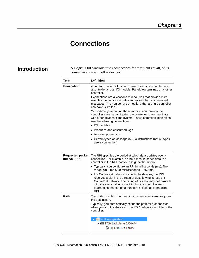
Path The path describes the route that a connection takes to get to the destination. Typically, you automatically define the path for a connection when you add the devices to the I/O Configuration folder of the controller.
Introduction
Chapter 1 Connections
12 Rockwell Automation Publication 1756-PM015I-EN-P - February 2018
In some situations, such as when initially commissioning a system, it is useful to disable portions of a control system and enable them as you physically connect the control system. The controller lets you inhibit individual modules or groups of modules, which prevents the controller from trying to communicate with the modules.
Inhibiting a module breaks the connection to the module and prevents communication of I/O data.
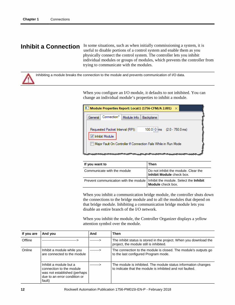
When you configure an I/O module, it defaults to not inhibited. You can change an individual module’s properties to inhibit a module.
If you want to Then
Communicate with the module Do not inhibit the module. Clear the Inhibit Module check box.
Prevent communication with the module Inhibit the module. Select the Inhibit Module check box.
When you inhibit a communication bridge module, the controller shuts down the connections to the bridge module and to all the modules that depend on that bridge module. Inhibiting a communication bridge module lets you disable an entire branch of the I/O network.
When you inhibit the module, the Controller Organizer displays a yellow attention symbol over the module.
If you are And you And Then
Offline ------------------------------> --------> The inhibit status is stored in the project. When you download the project, the module still is inhibited.
Online Inhibit a module while you are connected to the module
--------> The connection to the module is closed. The module's outputs go to the last configured Program mode.
Inhibit a module but a connection to the module was not established (perhaps due to an error condition or fault)
--------> The module is inhibited. The module status information changes to indicate that the module is inhibited and not faulted.
Inhibit a Connection
Connections Chapter 1
Rockwell Automation Publication 1756-PM015I-EN-P - February 2018 13
If you are And you And Then
Uninhibit a module (clear the check box)
No fault occurs
A connection is made to the module and the module is dynamically reconfigured (if the controller is the owner-controller) with the configuration you created for that module. If the controller is configured for listen-only, it cannot reconfigure the module.
Fault occurs A connection is not made to the module. The module status information changes to indicate the fault condition.
Follow these steps to inhibit or uninhibit a module from logic.
1. Use a Get System Value (GSV) instruction to read the Mode attribute for the module.
2. To inhibit the module, set bit 2. To uninhibit the module, clear bit 2.
3. Use a Set System Value (SSV) instruction to write the Mode attribute back to the module.
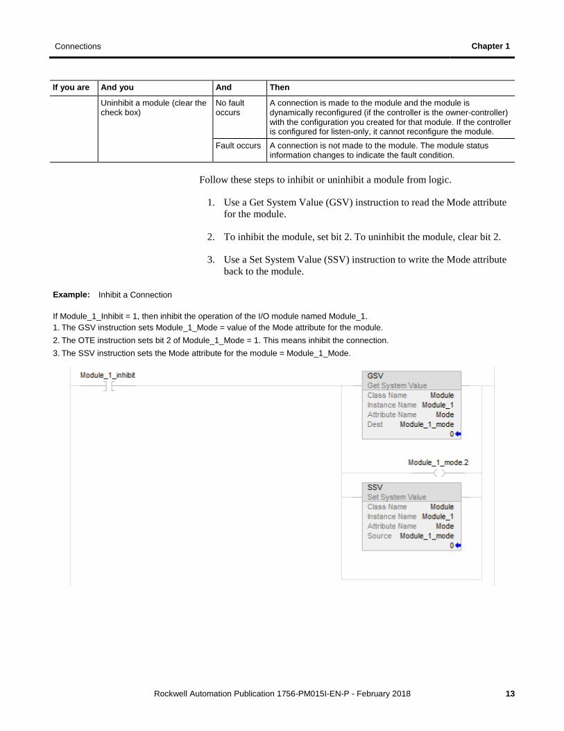
Example: Inhibit a Connection
If Module_1_Inhibit = 1, then inhibit the operation of the I/O module named Module_1. 1. The GSV instruction sets Module_1_Mode = value of the Mode attribute for the module. 2. The OTE instruction sets bit 2 of Module_1_Mode = 1. This means inhibit the connection. 3. The SSV instruction sets the Mode attribute for the module = Module_1_Mode.
Chapter 1 Connections
14 Rockwell Automation Publication 1756-PM015I-EN-P - February 2018
If the controller loses communication with a module, data from that device does not update. When this occurs, the logic acts on the data in ways that may or may not be correct. You can program the controller to manage faults safely and efficiently.
Outputs respond to the last, non-faulted state of the controlling inputs. To avoid potential injury and damage to machinery, make sure this does not create an unsafe operation. Configure critical I/O modules to generate a controller major fault when they lose their connections to the controller, or monitor the status of I/O modules.
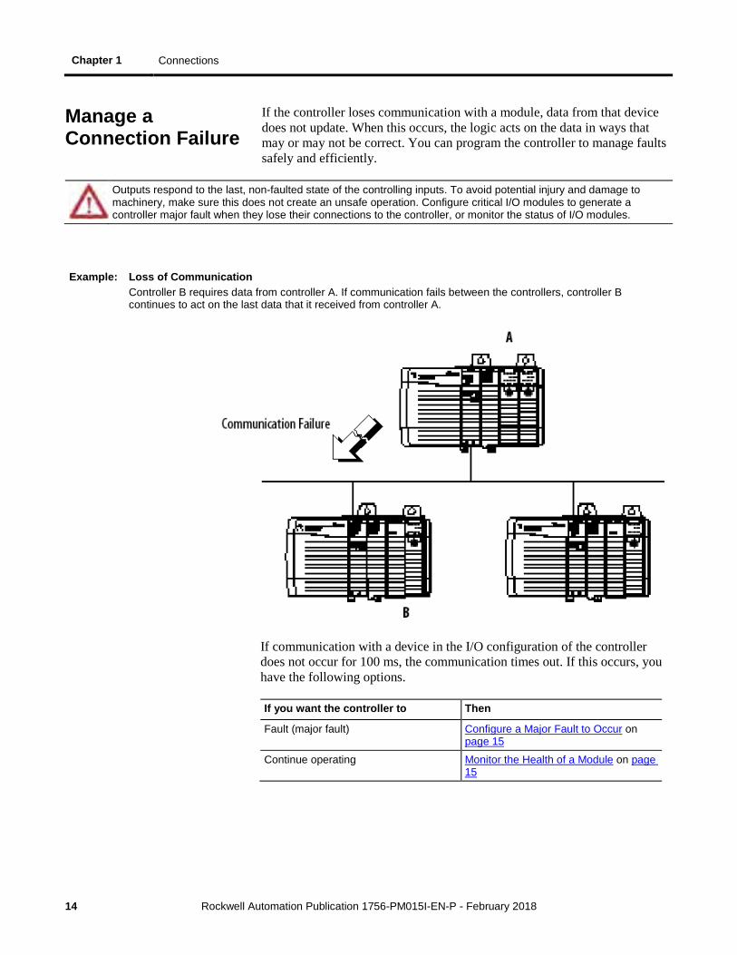
Example: Loss of Communication Controller B requires data from controller A. If communication fails between the controllers, controller B continues to act on the last data that it received from controller A.
If communication with a device in the I/O configuration of the controller does not occur for 100 ms, the communication times out. If this occurs, you have the following options.
If you want the controller to Then
Fault (major fault) Configure a Major Fault to Occur on page 15
Continue operating Monitor the Health of a Module on page 15
Manage a Connection Failure
Connections Chapter 1
Rockwell Automation Publication 1756-PM015I-EN-P - February 2018 15
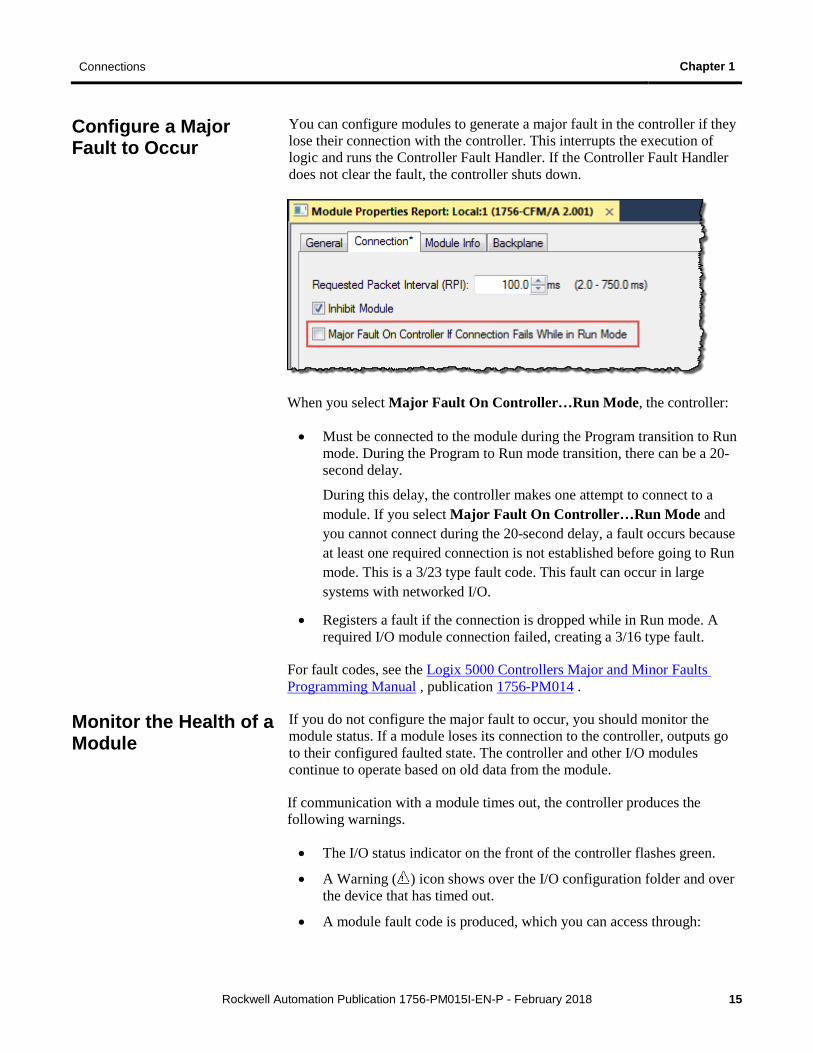
You can configure modules to generate a major fault in the controller if they lose their connection with the controller. This interrupts the execution of logic and runs the Controller Fault Handler. If the Controller Fault Handler does not clear the fault, the controller shuts down.
When you select Major Fault On Controller…Run Mode, the controller:
• Must be connected to the module during the Program transition to Run mode. During the Program to Run mode transition, there can be a 20-second delay.
During this delay, the controller makes one attempt to connect to a module. If you select Major Fault On Controller…Run Mode and you cannot connect during the 20-second delay, a fault occurs because at least one required connection is not established before going to Run mode. This is a 3/23 type fault code. This fault can occur in large systems with networked I/O.
• Registers a fault if the connection is dropped while in Run mode. A required I/O module connection failed, creating a 3/16 type fault.
For fault codes, see the Logix 5000 Controllers Major and Minor Faults Programming Manual , publication 1756-PM014 .
If you do not configure the major fault to occur, you should monitor the module status. If a module loses its connection to the controller, outputs go to their configured faulted state. The controller and other I/O modules continue to operate based on old data from the module.
If communication with a module times out, the controller produces the following warnings.
• The I/O status indicator on the front of the controller flashes green.
• A Warning ( ) icon shows over the I/O configuration folder and over the device that has timed out.
• A module fault code is produced, which you can access through:
Configure a Major Fault to Occur
Monitor the Health of a Module

Chapter 1 Connections
16 Rockwell Automation Publication 1756-PM015I-EN-P - February 2018
• Module Properties window for the module.
• GSV instruction.
To monitor the health of your connections, use a Get System Value (GSV) instruction to monitor the Module object for either the controller or a specific module.
If you want to Get this attribute Data Type Description
Determine if communication has timed out with any device
LEDStatus INT For efficiency, use a DINT as the destination data type.
Current state of the I/O status indicator on the front of the controller. You do not enter an instance name with this attribute. This attribute applies to the entire collection of modules. Value Meaning
0 Status Indicator off. No Module objects are configured for the controller (there are no modules in the I/O Configuration section of the controller organizer).
1 Flashing red. None of the Module objects are Running.
2 Flashing green. At least one Module object is not Running.
3 Solid green. All the Module objects are Running.
Determine if communication has timed out with a specific device
FaultCode INT For efficiency, use a DINT as the destination data type.
A number that identifies a module fault, if one occurs. In the Instance Name, choose the device whose connection you want to monitor. Make sure to assign a name to the device in the I/O Configuration folder of the project.
If Module_Status is any value other than 4, the controller is not communicating with the module. See the following example.
Connections Chapter 1
Rockwell Automation Publication 1756-PM015I-EN-P - February 2018 17
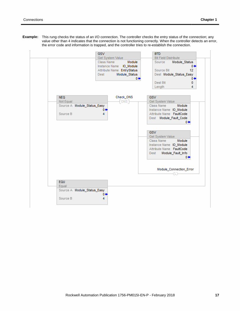
Example: This rung checks the status of an I/O connection. The controller checks the entry status of the connection; any value other than 4 indicates that the connection is not functioning correctly. When the controller detects an error, the error code and information is trapped, and the controller tries to re-establish the connection.

Rockwell Automation Publication 1756-PM015I-EN-P - February 2018 19
Chapter 2
Determine Controller Memory Information
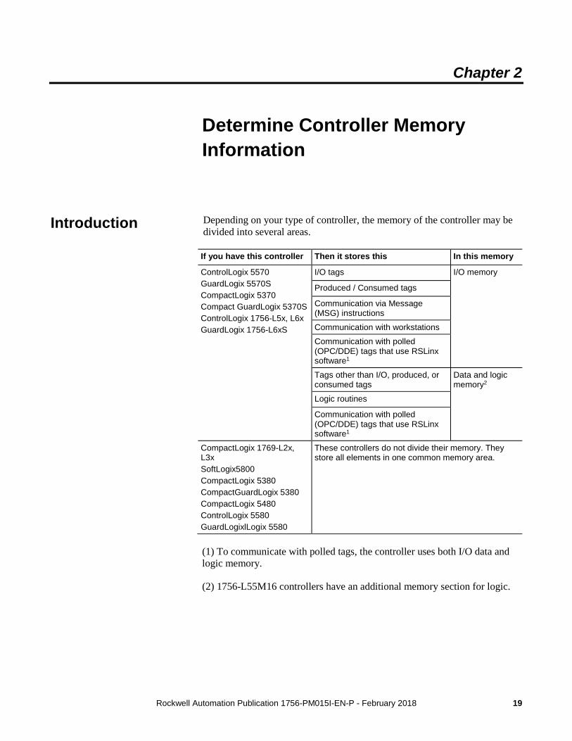
Depending on your type of controller, the memory of the controller may be divided into several areas.
If you have this controller Then it stores this In this memory
ControlLogix 5570 GuardLogix 5570S CompactLogix 5370 Compact GuardLogix 5370S ControlLogix 1756-L5x, L6x GuardLogix 1756-L6xS
I/O tags I/O memory
Produced / Consumed tags
Communication via Message (MSG) instructions
Communication with workstations
Communication with polled (OPC/DDE) tags that use RSLinx software1
Tags other than I/O, produced, or consumed tags
Data and logic memory2
Logic routines
Communication with polled (OPC/DDE) tags that use RSLinx software1
CompactLogix 1769-L2x, L3x SoftLogix5800 CompactLogix 5380 CompactGuardLogix 5380 CompactLogix 5480 ControlLogix 5580 GuardLogixlLogix 5580
These controllers do not divide their memory. They store all elements in one common memory area.
(1) To communicate with polled tags, the controller uses both I/O data and logic memory.
(2) 1756-L55M16 controllers have an additional memory section for logic.
Introduction
Chapter 2 Determine Controller Memory Information
20 Rockwell Automation Publication 1756-PM015I-EN-P - February 2018
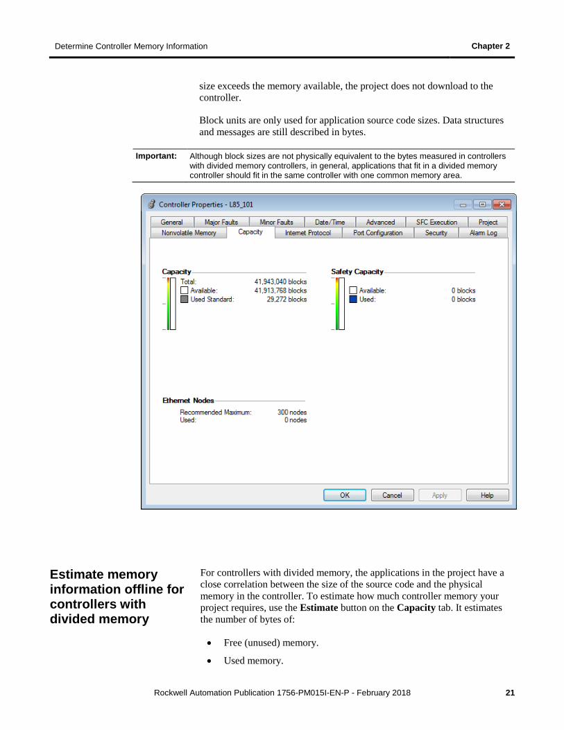
In Logix Designer application, the Capacity tab (formerly the Memory tab) on the Controller Properties dialog box shows data usage in the controller. The data displayed on the Capacity tab depends on the controller.
Tip: Refer to the table on page 19 to see whether a controller divides its memory or has one common memory area.
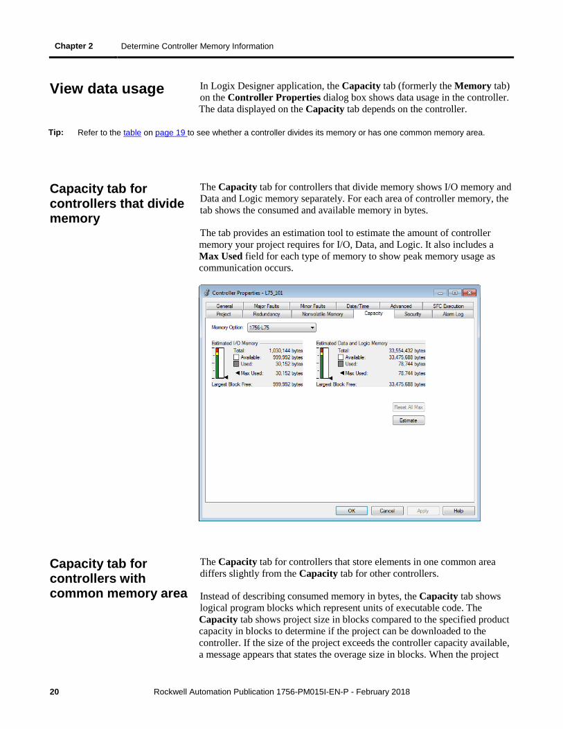
The Capacity tab for controllers that divide memory shows I/O memory and Data and Logic memory separately. For each area of controller memory, the tab shows the consumed and available memory in bytes.
The tab provides an estimation tool to estimate the amount of controller memory your project requires for I/O, Data, and Logic. It also includes a Max Used field for each type of memory to show peak memory usage as communication occurs.
The Capacity tab for controllers that store elements in one common area differs slightly from the Capacity tab for other controllers.
Instead of describing consumed memory in bytes, the Capacity tab shows logical program blocks which represent units of executable code. The Capacity tab shows project size in blocks compared to the specified product capacity in blocks to determine if the project can be downloaded to the controller. If the size of the project exceeds the controller capacity available, a message appears that states the overage size in blocks. When the project
View data usage
Capacity tab for controllers that divide memory
Capacity tab for controllers with common memory area
Determine Controller Memory Information Chapter 2
Rockwell Automation Publication 1756-PM015I-EN-P - February 2018 21
size exceeds the memory available, the project does not download to the controller.
Block units are only used for application source code sizes. Data structures and messages are still described in bytes.
Important: Although block sizes are not physically equivalent to the bytes measured in controllers with divided memory controllers, in general, applications that fit in a divided memory controller should fit in the same controller with one common memory area.
For controllers with divided memory, the applications in the project have a close correlation between the size of the source code and the physical memory in the controller. To estimate how much controller memory your project requires, use the Estimate button on the Capacity tab. It estimates the number of bytes of:
• Free (unused) memory.
• Used memory.
Estimate memory information offline for controllers with divided memory
Chapter 2 Determine Controller Memory Information
22 Rockwell Automation Publication 1756-PM015I-EN-P - February 2018
• Largest free contiguous block of memory.
Tip: This section only applies to controllers with divided memory. Refer to the table on page 19 for a list of controllers with divided memory. Refer to Capacity tab for controllers with common memory area on page 20 for information about the other controllers.
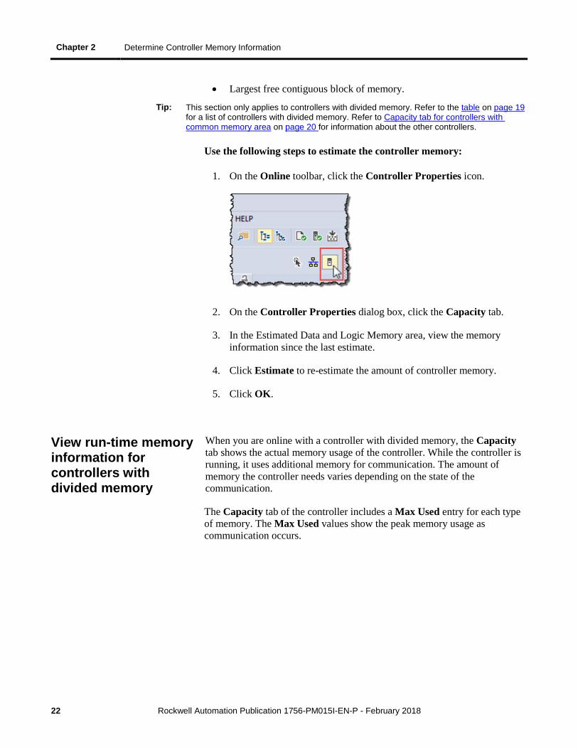
Use the following steps to estimate the controller memory:
1. On the Online toolbar, click the Controller Properties icon.
2. On the Controller Properties dialog box, click the Capacity tab.
3. In the Estimated Data and Logic Memory area, view the memory information since the last estimate.
4. Click Estimate to re-estimate the amount of controller memory.
5. Click OK.
When you are online with a controller with divided memory, the Capacity tab shows the actual memory usage of the controller. While the controller is running, it uses additional memory for communication. The amount of memory the controller needs varies depending on the state of the communication.
The Capacity tab of the controller includes a Max Used entry for each type of memory. The Max Used values show the peak memory usage as communication occurs.
View run-time memory information for controllers with divided memory
Determine Controller Memory Information Chapter 2
Rockwell Automation Publication 1756-PM015I-EN-P - February 2018 23
Tip: This section applies only to controllers with divided memory. Refer to the table on page 19 for a list of controllers with divided memory. Refer to Capacity tab for controllers with common memory area on page 20 for information about the other controllers.
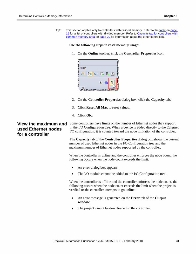
Use the following steps to reset memory usage:
1. On the Online toolbar, click the Controller Properties icon.
2. On the Controller Properties dialog box, click the Capacity tab.
3. Click Reset All Max to reset values.
4. Click OK.
Some controllers have limits on the number of Ethernet nodes they support in the I/O Configuration tree. When a device is added directly to the Ethernet I/O configuration, it is counted toward the node limitation of the controller.
The Capacity tab of the Controller Properties dialog box shows the current number of used Ethernet nodes in the I/O Configuration tree and the maximum number of Ethernet nodes supported by the controller.
When the controller is online and the controller enforces the node count, the following occurs when the node count exceeds the limit:
• An error dialog box appears.
• The I/O module cannot be added to the I/O Configuration tree.
When the controller is offline and the controller enforces the node count, the following occurs when the node count exceeds the limit when the project is verified or the controller attempts to go online:
• An error message is generated on the Error tab of the Output window.
• The project cannot be downloaded to the controller.
View the maximum and used Ethernet nodes for a controller
Chapter 2 Determine Controller Memory Information
24 Rockwell Automation Publication 1756-PM015I-EN-P - February 2018
Tip: The 1756-L85E controllers do not enforce the node count, meaning the system does not prohibit you from connecting additional nodes, and it may be possible to download the project. The system provides a warning when the recommended node limit has been exceeded.
To view the maximum and used Ethernet nodes for a controller:
1. On the Online toolbar, click the Controller Properties icon.
2. On the Controller Properties dialog box, click the Capacity tab.
3. In the Ethernet Node group, view the information about the Ethernet nodes.
• Maximum/Recommended Maximum - shows the maximum or recommended maximum number of Ethernet nodes for the controller
• Used - shows the current number of Ethernet nodes in the I/O Configuration tree
If the number of used Ethernet nodes exceeds the maximum number, appears next to the Used parameter when controller is offline.
For the 1756-L85E controllers, if the node count exceeds the recommended limit, appears next to the Used parameter and the following message appears:
The recommended node limit has been exceeded. It may be possible to connect additional nodes depending on the node type and system architecture.
Use a Message (MSG) instruction to get memory information from the controller.
Tip: This procedure applies to controllers with divided memory. The Logix Designer application determines capacity information for controllers that store elements in one common area.
Write logic to get memory information
Determine Controller Memory Information Chapter 2
Rockwell Automation Publication 1756-PM015I-EN-P - February 2018 25
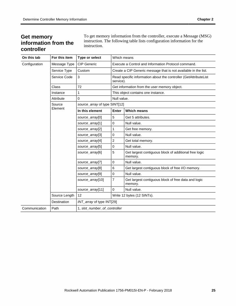
To get memory information from the controller, execute a Message (MSG) instruction. The following table lists configuration information for the instruction.
On this tab For this item Type or select Which means
Configuration Message Type CIP Generic Execute a Control and Information Protocol command.
Service Type Custom Create a CIP Generic message that is not available in the list.
Service Code 3 Read specific information about the controller (GetAttributeList service).
Class 72 Get information from the user memory object.
Instance 1 This object contains one instance.
Attribute 0 Null value.
Source Element
source_array of type SINT[12]
In this element Enter Which means
source_array[0] 5 Get 5 attributes.
source_array[1] 0 Null value.
source_array[2] 1 Get free memory.
source_array[3] 0 Null value. source_array[4] 2 Get total memory.
source_array[5] 0 Null value.
source_array[6] 5 Get largest contiguous block of additional free logic memory.
source_array[7] 0 Null value.
source_array[8] 6 Get largest contiguous block of free I/O memory.
source_array[9] 0 Null value.
source_array[10] 7 Get largest contiguous block of free data and logic memory.
source_array[11] 0 Null value.
Source Length 12 Write 12 bytes (12 SINTs).
Destination INT_array of type INT[29]
Communication Path 1, slot_number_of_controller
Get memory information from the controller
Chapter 2 Determine Controller Memory Information
26 Rockwell Automation Publication 1756-PM015I-EN-P - February 2018
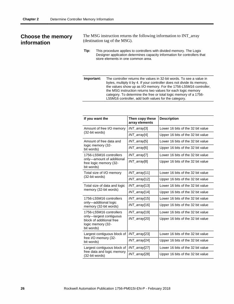
The MSG instruction returns the following information to INT_array (destination tag of the MSG).
Tip: This procedure applies to controllers with divided memory. The Logix Designer application determines capacity information for controllers that store elements in one common area.
Important: The controller returns the values in 32-bit words. To see a value in bytes, multiply it by 4. If your controller does not divide its memory, the values show up as I/O memory. For the 1756-L55M16 controller, the MSG instruction returns two values for each logic memory category. To determine the free or total logic memory of a 1756-L55M16 controller, add both values for the category.
If you want the Then copy these array elements
Description
Amount of free I/O memory (32-bit words)
INT_array[3] Lower 16 bits of the 32 bit value
INT_array[4] Upper 16 bits of the 32 bit value
Amount of free data and logic memory (32-bit words)
INT_array[5] Lower 16 bits of the 32 bit value
INT_array[6] Upper 16 bits of the 32 bit value
1756-L55M16 controllers only—amount of additional free logic memory (32-bit words)
INT_array[7] Lower 16 bits of the 32 bit value
INT_array[8] Upper 16 bits of the 32 bit value
Total size of I/O memory (32-bit words)
INT_array[11] Lower 16 bits of the 32 bit value
INT_array[12] Upper 16 bits of the 32 bit value
Total size of data and logic memory (32-bit words)
INT_array[13] Lower 16 bits of the 32 bit value
INT_array[14] Upper 16 bits of the 32 bit value
1756-L55M16 controllers only—additional logic memory (32-bit words)
INT_array[15] Lower 16 bits of the 32 bit value
INT_array[16] Upper 16 bits of the 32 bit value
1756-L55M16 controllers only—largest contiguous block of additional free logic memory (32-bit words)
INT_array[19] Lower 16 bits of the 32 bit value
INT_array[20] Upper 16 bits of the 32 bit value
Largest contiguous block of free I/O memory (32-bit words)
INT_array[23] Lower 16 bits of the 32 bit value
INT_array[24] Upper 16 bits of the 32 bit value
Largest contiguous block of free data and logic memory (32-bit words)
INT_array[27] Lower 16 bits of the 32 bit value
INT_array[28] Upper 16 bits of the 32 bit value
Choose the memory information
Determine Controller Memory Information Chapter 2
Rockwell Automation Publication 1756-PM015I-EN-P - February 2018 27
The MSG instruction returns each memory value as two separate INTs.
• The first INT represents the lower 16 bits of the value.
• The second INT represents the upper 16 bits of the value.
To convert the separate INTs into one usable value, use a Copy (COP) instruction.
In this operand Specify Which means
Source First INT of the 2 element pair (lower 16 bits)
Start with the lower 16 bits.
Destination DINT tag in which to store the 32-bit value
Copy the value to the DINT tag.
Length 1 Copy 1 times the number of bytes in the Destination data type. In this case, the instruction copies 4 bytes (32 bits), which combines the lower and upper 16 bits into one 32-bit value.
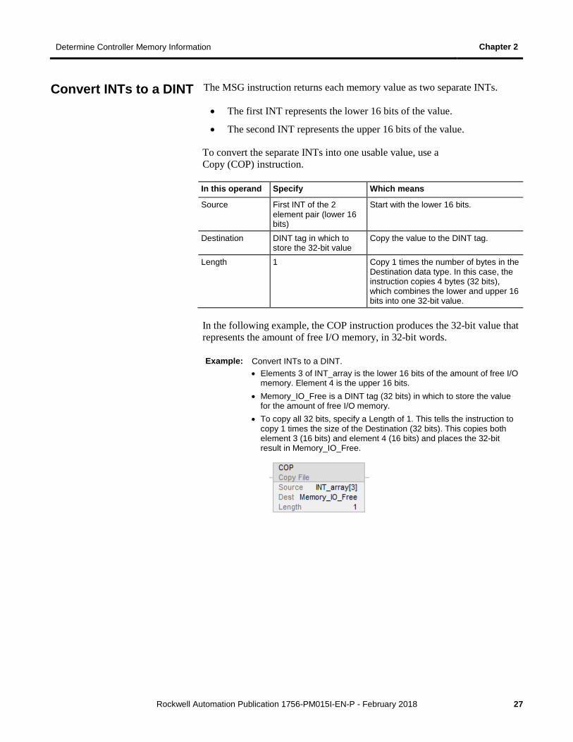
In the following example, the COP instruction produces the 32-bit value that represents the amount of free I/O memory, in 32-bit words.
Example: Convert INTs to a DINT. • Elements 3 of INT_array is the lower 16 bits of the amount of free I/O
memory. Element 4 is the upper 16 bits. • Memory_IO_Free is a DINT tag (32 bits) in which to store the value
for the amount of free I/O memory. • To copy all 32 bits, specify a Length of 1. This tells the instruction to
copy 1 times the size of the Destination (32 bits). This copies both element 3 (16 bits) and element 4 (16 bits) and places the 32-bit result in Memory_IO_Free.
Convert INTs to a DINT

Rockwell Automation Publication 1756-PM015I-EN-P - February 2018 29
Chapter 3
Controller Logging
You use the controller logging feature to detect and log changes made to Logix5000 controllers without adding any auditing software. With controller logging, the controllers:
• Detect changes and create logs entries containing information about the changes.
• Store the log entries to removable media for later review.
• Provide programmatic access to log entry counters to provide change detection information remotely.
Note the following logging considerations:
• The 1769-L3x and 1769-L4x CompactLogix Controllers do not support storing log entries to removable media, and the audit value is not populated.
• The Audit Value is not supported in versions 19 and earlier.
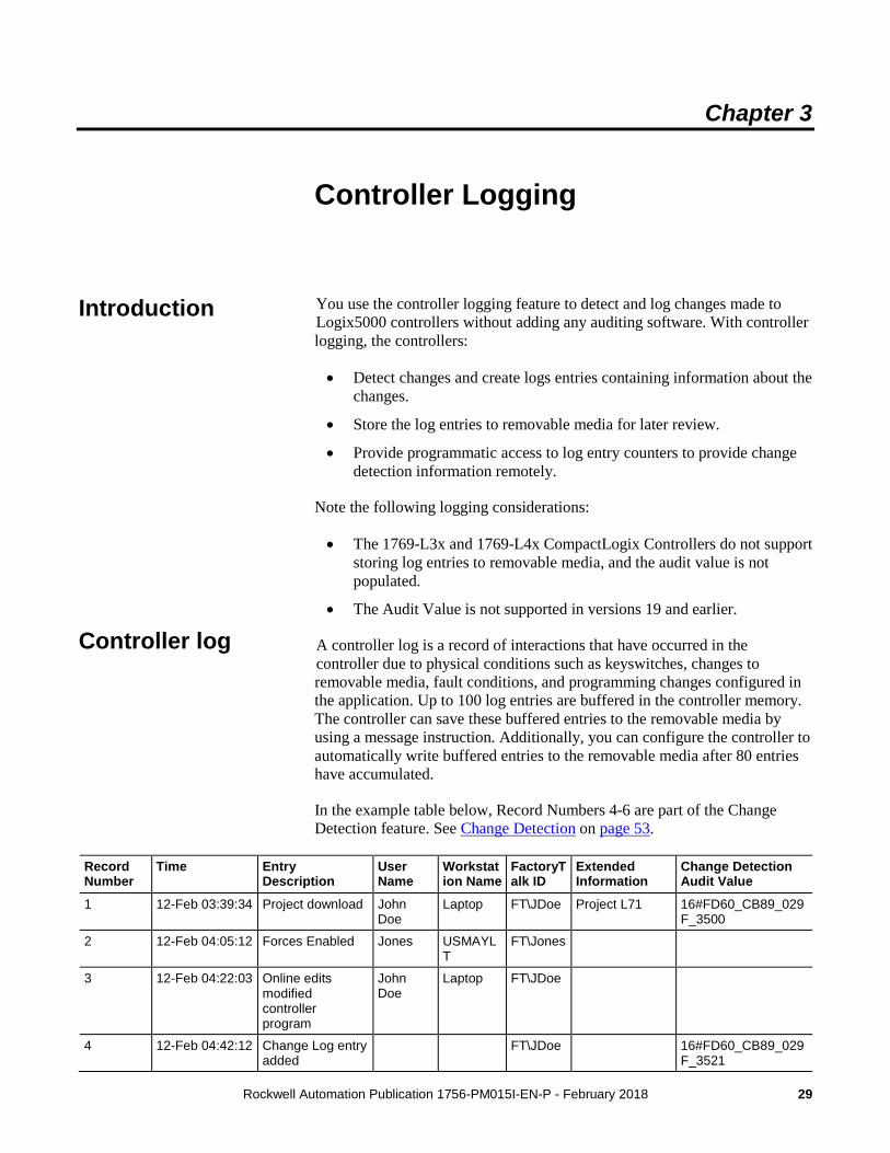
A controller log is a record of interactions that have occurred in the controller due to physical conditions such as keyswitches, changes to removable media, fault conditions, and programming changes configured in the application. Up to 100 log entries are buffered in the controller memory. The controller can save these buffered entries to the removable media by using a message instruction. Additionally, you can configure the controller to automatically write buffered entries to the removable media after 80 entries have accumulated.
In the example table below, Record Numbers 4-6 are part of the Change Detection feature. See Change Detection on page 53.
Record Number
Time Entry Description
User Name
Workstation Name
FactoryTalk ID
Extended Information
Change Detection Audit Value
1 12-Feb 03:39:34 Project download John Doe
Laptop FT\JDoe Project L71 16#FD60_CB89_029F_3500
2 12-Feb 04:05:12 Forces Enabled Jones USMAYLT
FT\Jones
3 12-Feb 04:22:03 Online edits modified controller program
John Doe
Laptop FT\JDoe
4 12-Feb 04:42:12 Change Log entry added
FT\JDoe 16#FD60_CB89_029F_3521
Introduction
Controller log
Chapter 3 Controller Logging
30 Rockwell Automation Publication 1756-PM015I-EN-P - February 2018
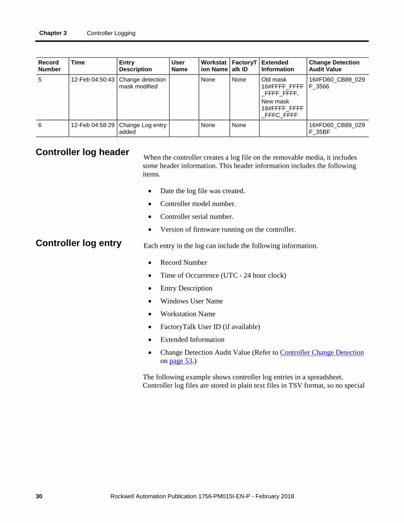
Record Number
Time Entry Description
User Name
Workstation Name
FactoryTalk ID
Extended Information
Change Detection Audit Value
5 12-Feb 04:50:43 Change detection mask modified
None None Old mask 16#FFFF_FFFF_FFFF_FFFF, New mask 16#FFFF_FFFF_FFFC_FFFF
16#FD60_CB89_029F_3566
6 12-Feb 04:58:29 Change Log entry added
None None 16#FD60_CB89_029F_35BF
When the controller creates a log file on the removable media, it includes some header information. This header information includes the following items.
• Date the log file was created.
• Controller model number.
• Controller serial number.
• Version of firmware running on the controller.
Each entry in the log can include the following information.
• Record Number
• Time of Occurrence (UTC - 24 hour clock)
• Entry Description
• Windows User Name
• Workstation Name
• FactoryTalk User ID (if available)
• Extended Information
• Change Detection Audit Value (Refer to Controller Change Detection on page 53.)
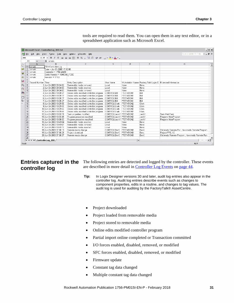
The following example shows controller log entries in a spreadsheet. Controller log files are stored in plain text files in TSV format, so no special
Controller log header
Controller log entry
Controller Logging Chapter 3
Rockwell Automation Publication 1756-PM015I-EN-P - February 2018 31
tools are required to read them. You can open them in any text editor, or in a spreadsheet application such as Microsoft Excel.
The following entries are detected and logged by the controller. These events are described in more detail in Controller Log Events on page 44.
Tip: In Logix Designer versions 30 and later, audit log entries also appear in the controller log. Audit log entries describe events such as changes to component properties, edits in a routine, and changes to tag values. The audit log is used for auditing by the FactoryTalk® AssetCentre.
• Project downloaded
• Project loaded from removable media
• Project stored to removable media
• Online edits modified controller program
• Partial import online completed or Transaction committed
• I/O forces enabled, disabled, removed, or modified
• SFC forces enabled, disabled, removed, or modified
• Firmware update
• Constant tag data changed
• Multiple constant tag data changed
Entries captured in the controller log
Chapter 3 Controller Logging
32 Rockwell Automation Publication 1756-PM015I-EN-P - February 2018
• Change to constant tag configuration reset
• Mode change
• Major fault, major fault cleared
• Program properties modified
• Task properties modified
• Controller timeslice modified
• Removable media inserted or removed
• Safety signature created or deleted
• Safety locked or unlocked
• Custom entry: User-defined logic to create a log entry, with user-defined entry description and extended information
• Safety signature delete inhibited in Run mode
• Safety signature delete allowed in Run mode
• The Changes To Detect value has changed
• Log Collected Data Cleared
• Program Connection Modified
The controller keeps up to 100 log entries buffered in its internal memory. You can configure the controller to write the buffered entries to the removable media when its internal buffer is 80% full. Additionally, you can command the controller to write the buffered entries to the removable media with a message instruction. This procedure is detailed below. Once a log entry is written to the removable media, it is removed from the buffer.
If the removable media is not present, is full, or if the controller is not configured to automatically write buffered entries to the removable media, and the internal buffer becomes full, entries continue to be saved in the buffer in a circular fashion. As new entries are stored, the oldest entries are discarded.
When written to the removable media, controller logs are stored in plain text files in the Tab Separated Value (TSV) format. Each time the controller writes entries to the CompactFlash card, the entries are appended to the text file until the file reaches 1 MB in size. At this point, the controller creates a new text file.
The controller does not attempt to write log entries to a full removable media card. If the removable media becomes full, the system behaves as if the removable media is not present.
Controller log files are stored in plain text files in the TSV format, so no special tools are required to read them. You can open them in any text editor, or in a spreadsheet application such as Microsoft Excel.
Controller Log Buffer
Controller Log Files and the Removable Media

Controller Logging Chapter 3
Rockwell Automation Publication 1756-PM015I-EN-P - February 2018 33
The controller log can be written to the Secure Digital (SD) card either automatically or on demand.
Tip: Some Logix 5000 controllers support additional types of removable media that can be used to write the controller log entries. Refer to the Logix 5000 controller documentation for information regarding the type of removable media your controller supports.
You can configure the controller to automatically write buffered log entries to the SD card when the controller's internal log entry buffer becomes 80% full. You can also configure the controller to write the buffered entries before a firmware update. To write buffered entries before a firmware update, send a message instruction to the controller using a CIP Generic message type and a service type of Controller Log Automatic Write Set. Sending a value of 0 turns off automatic writes, and sending a value of 1 turns on automatic writes. By default, entries are not automatically written.
A rung of logic that performs this configuration and the configuration dialog box of the message instruction are shown in the following examples.
Example: Automatic Save Set ladder instruction and configuration dialog box
Writing the Controller Log to the SD Card
Automatic Save
Chapter 3 Controller Logging
34 Rockwell Automation Publication 1756-PM015I-EN-P - February 2018
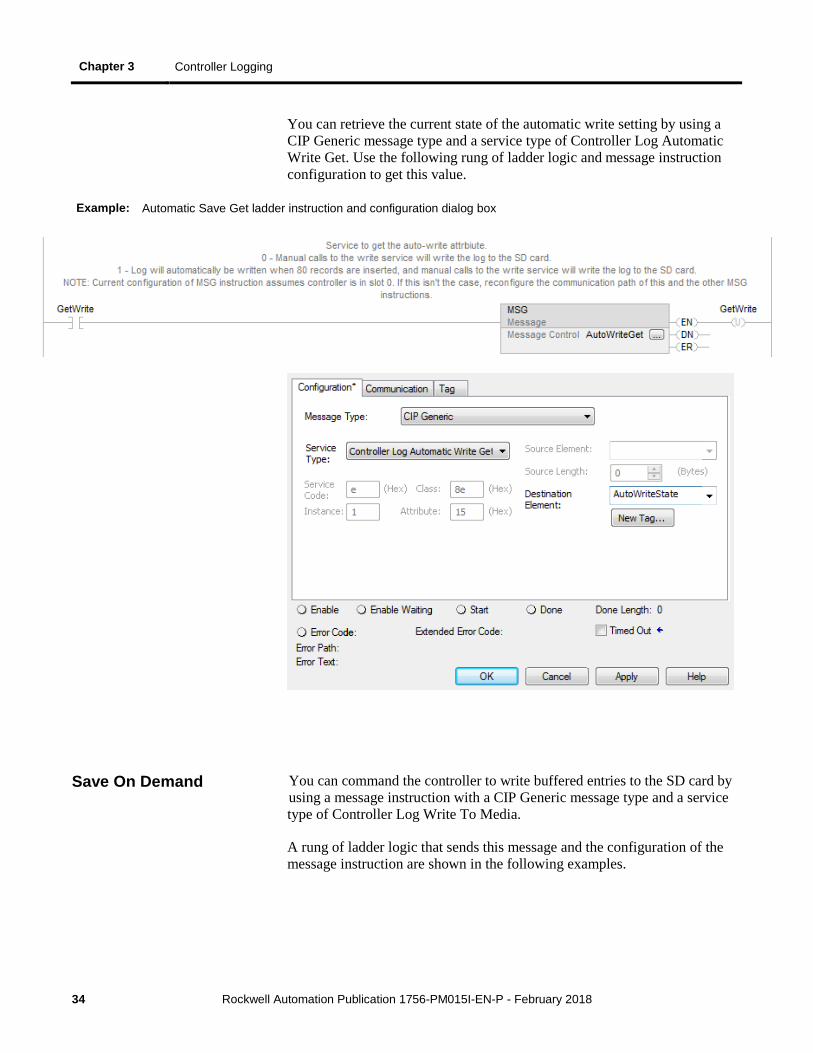
You can retrieve the current state of the automatic write setting by using a CIP Generic message type and a service type of Controller Log Automatic Write Get. Use the following rung of ladder logic and message instruction configuration to get this value.
Example: Automatic Save Get ladder instruction and configuration dialog box
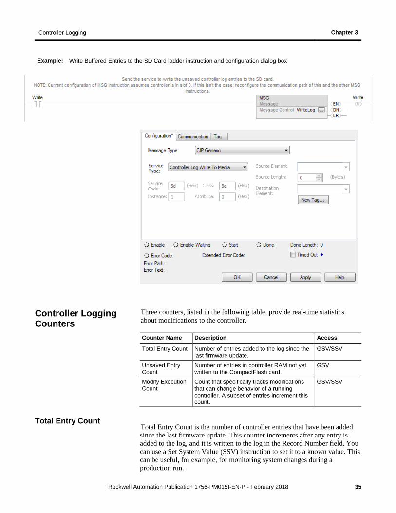
You can command the controller to write buffered entries to the SD card by using a message instruction with a CIP Generic message type and a service type of Controller Log Write To Media.
A rung of ladder logic that sends this message and the configuration of the message instruction are shown in the following examples.
Save On Demand
Controller Logging Chapter 3
Rockwell Automation Publication 1756-PM015I-EN-P - February 2018 35
Example: Write Buffered Entries to the SD Card ladder instruction and configuration dialog box
Three counters, listed in the following table, provide real-time statistics about modifications to the controller.
Counter Name Description Access
Total Entry Count Number of entries added to the log since the last firmware update.
GSV/SSV
Unsaved Entry Count
Number of entries in controller RAM not yet written to the CompactFlash card.
GSV
Modify Execution Count
Count that specifically tracks modifications that can change behavior of a running controller. A subset of entries increment this count.
GSV/SSV
Total Entry Count is the number of controller entries that have been added since the last firmware update. This counter increments after any entry is added to the log, and it is written to the log in the Record Number field. You can use a Set System Value (SSV) instruction to set it to a known value. This can be useful, for example, for monitoring system changes during a production run.
Controller Logging Counters
Total Entry Count
Chapter 3 Controller Logging
36 Rockwell Automation Publication 1756-PM015I-EN-P - February 2018
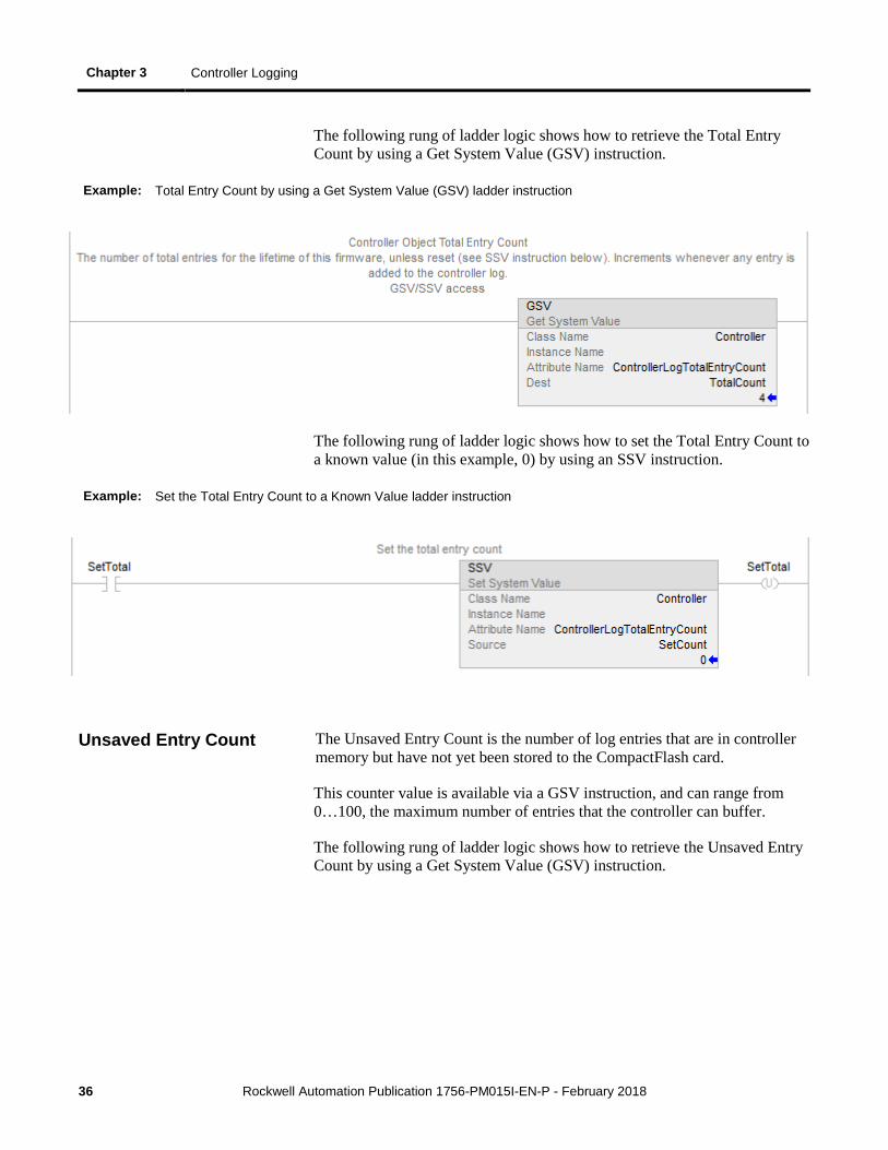
The following rung of ladder logic shows how to retrieve the Total Entry Count by using a Get System Value (GSV) instruction.
Example: Total Entry Count by using a Get System Value (GSV) ladder instruction
The following rung of ladder logic shows how to set the Total Entry Count to a known value (in this example, 0) by using an SSV instruction.
Example: Set the Total Entry Count to a Known Value ladder instruction
The Unsaved Entry Count is the number of log entries that are in controller memory but have not yet been stored to the CompactFlash card.
This counter value is available via a GSV instruction, and can range from 0…100, the maximum number of entries that the controller can buffer.
The following rung of ladder logic shows how to retrieve the Unsaved Entry Count by using a Get System Value (GSV) instruction.
Unsaved Entry Count
Controller Logging Chapter 3
Rockwell Automation Publication 1756-PM015I-EN-P - February 2018 37
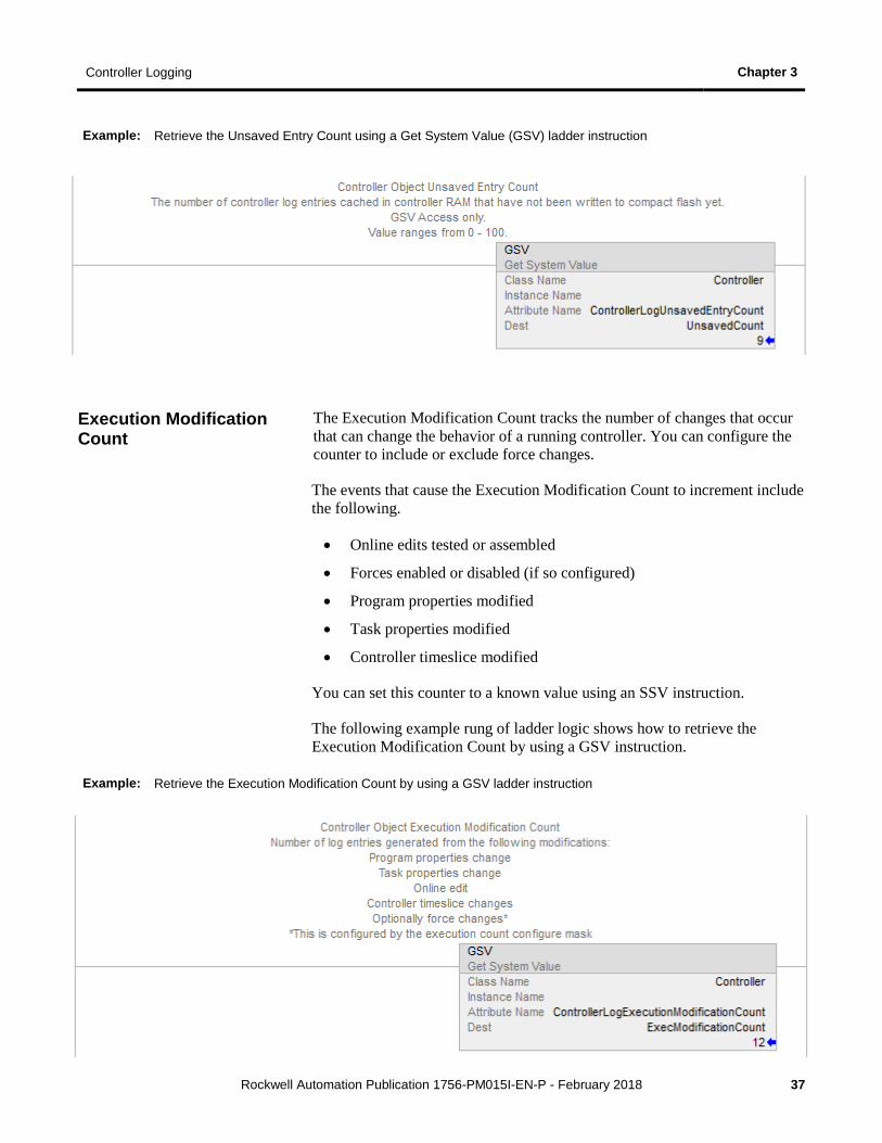
Example: Retrieve the Unsaved Entry Count using a Get System Value (GSV) ladder instruction
The Execution Modification Count tracks the number of changes that occur that can change the behavior of a running controller. You can configure the counter to include or exclude force changes.
The events that cause the Execution Modification Count to increment include the following.
• Online edits tested or assembled
• Forces enabled or disabled (if so configured)
• Program properties modified
• Task properties modified
• Controller timeslice modified
You can set this counter to a known value using an SSV instruction.
The following example rung of ladder logic shows how to retrieve the Execution Modification Count by using a GSV instruction.
Example: Retrieve the Execution Modification Count by using a GSV ladder instruction
Execution Modification Count

Chapter 3 Controller Logging
38 Rockwell Automation Publication 1756-PM015I-EN-P - February 2018
The following rung of ladder logic shows how to set the Execution Modification Count to a known value.
Example: Ladder instruction to set the Execution Modification Count to a known value
You use a message instruction of message type CIP Generic and a service type of Controller Log Config Execution Set to configure whether the Execution Modification Count includes forces.
If it is sent a value of 1, forces are included in the counter. If it is sent a value of 0, forces are not included.
The following rung of ladder logic shows how to send the message instruction, followed by the configuration dialog box of the message instruction.
Controller Logging Chapter 3
Rockwell Automation Publication 1756-PM015I-EN-P - February 2018 39
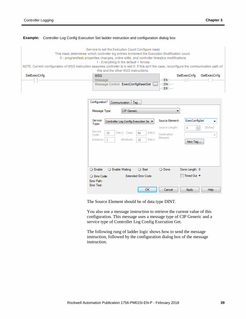
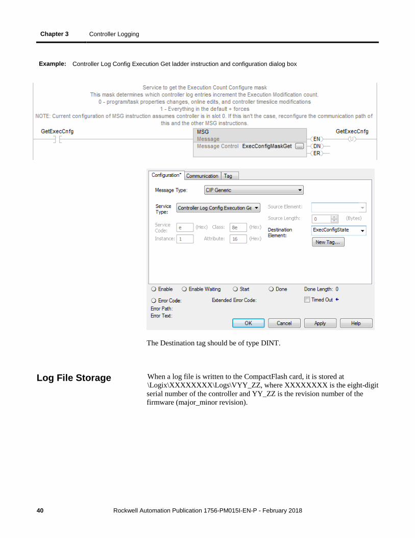
Example: Controller Log Config Execution Set ladder instruction and configuration dialog box
The Source Element should be of data type DINT.
You also use a message instruction to retrieve the current value of this configuration. This message uses a message type of CIP Generic and a service type of Controller Log Config Execution Get.
The following rung of ladder logic shows how to send the message instruction, followed by the configuration dialog box of the message instruction.
Chapter 3 Controller Logging
40 Rockwell Automation Publication 1756-PM015I-EN-P - February 2018
Example: Controller Log Config Execution Get ladder instruction and configuration dialog box
The Destination tag should be of type DINT.
When a log file is written to the CompactFlash card, it is stored at \Logix\XXXXXXXX\Logs\VYY_ZZ, where XXXXXXXX is the eight-digit serial number of the controller and YY_ZZ is the revision number of the firmware (major_minor revision).
Log File Storage
Controller Logging Chapter 3
Rockwell Automation Publication 1756-PM015I-EN-P - February 2018 41
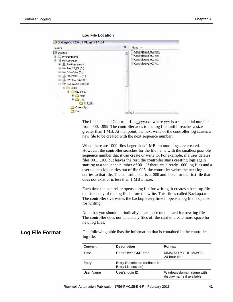
Log File Location
The file is named ControllerLog_yyy.txt, where yyy is a sequential number from 000…999. The controller adds to the log file until it reaches a size greater than 1 MB. At that point, the next write of the controller log causes a new file to be created with the next sequence number.
When there are 1000 files larger than 1 MB, no more logs are created. However, the controller searches for the file name with the smallest possible sequence number that it can create or write to. For example, if a user deletes files 001…100 but leaves the rest, the controller starts creating logs again starting at a sequence number of 001. If there are already 1000 log files and a user deletes log entries out of file 005, the controller writes the next log entries to that file. The controller starts at 000 and looks for the first file that does not exist or is less than 1 MB in size.
Each time the controller opens a log file for writing, it creates a back-up file that is a copy of the log file before the write. This file is called Backup.txt. The controller overwrites the backup every time it opens a log file is opened for writing.
Note that you should periodically clear space on the card for new log files. The controller does not delete any files off the card to create more space for new log files.
The following table lists the information that is contained in the controller log file.
Content Description Format
Time Controller's GMT time MMM-DD-YY HH:MM:SS 24-hour time
Entry Entry Description (defined in Entry List section)
User Name User's login ID Windows domain name with display name if available
Log File Format
Chapter 3 Controller Logging
42 Rockwell Automation Publication 1756-PM015I-EN-P - February 2018
Content Description Format
Workstation Name User's computer name Computer Name
FactoryTalk ID User's FactoryTalk login ID Alphanumeric characters
Extended Information
Entry specific information (defined in Entry List section)
Change Detection Audit Value1
Changes that the controller detected in the Audit value
(1) Version 20 or later. See Change Detection on page 57.
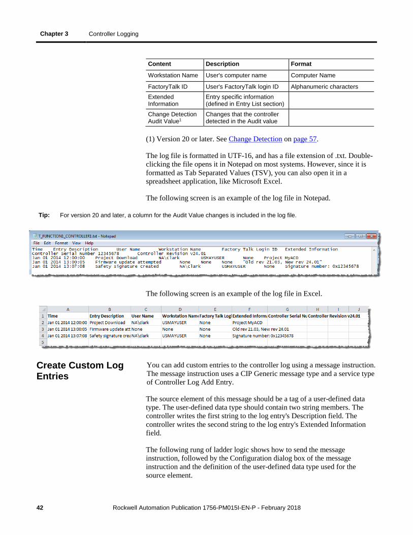
The log file is formatted in UTF-16, and has a file extension of .txt. Double-clicking the file opens it in Notepad on most systems. However, since it is formatted as Tab Separated Values (TSV), you can also open it in a spreadsheet application, like Microsoft Excel.
The following screen is an example of the log file in Notepad.
Tip: For version 20 and later, a column for the Audit Value changes is included in the log file.
The following screen is an example of the log file in Excel.
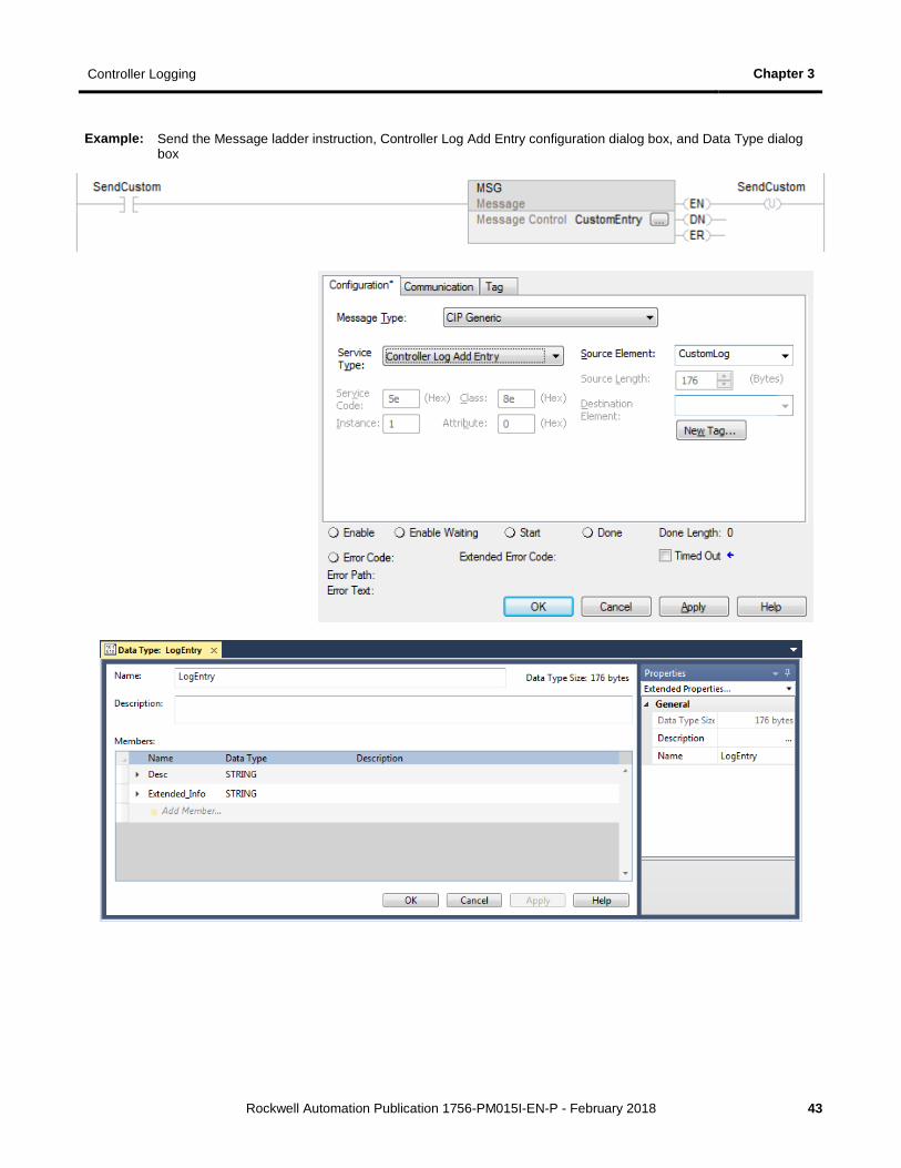
You can add custom entries to the controller log using a message instruction. The message instruction uses a CIP Generic message type and a service type of Controller Log Add Entry.
The source element of this message should be a tag of a user-defined data type. The user-defined data type should contain two string members. The controller writes the first string to the log entry's Description field. The controller writes the second string to the log entry's Extended Information field.
The following rung of ladder logic shows how to send the message instruction, followed by the Configuration dialog box of the message instruction and the definition of the user-defined data type used for the source element.
Create Custom Log Entries
Controller Logging Chapter 3
Rockwell Automation Publication 1756-PM015I-EN-P - February 2018 43
Example: Send the Message ladder instruction, Controller Log Add Entry configuration dialog box, and Data Type dialog box
Chapter 3 Controller Logging
44 Rockwell Automation Publication 1756-PM015I-EN-P - February 2018
In the Logix Designer application, there is a controller logging sample ladder file. If you installed the sample files during the installation, you can open the sample files from the Help menu. On the Help menu, select Vendor Sample Projects.
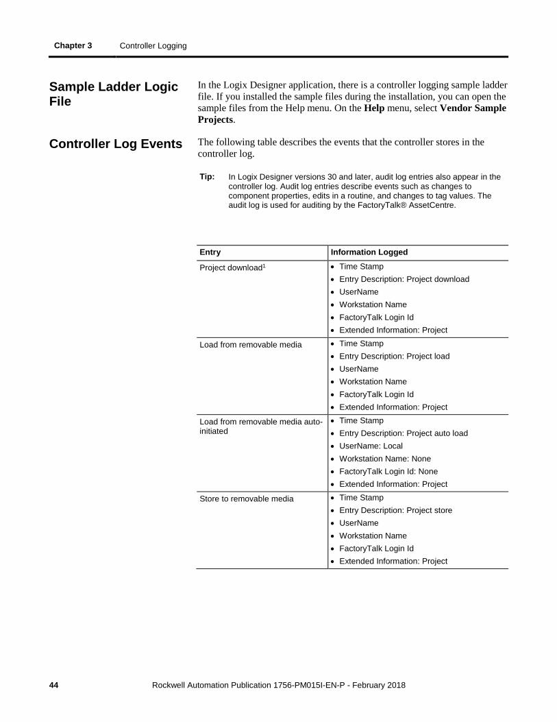
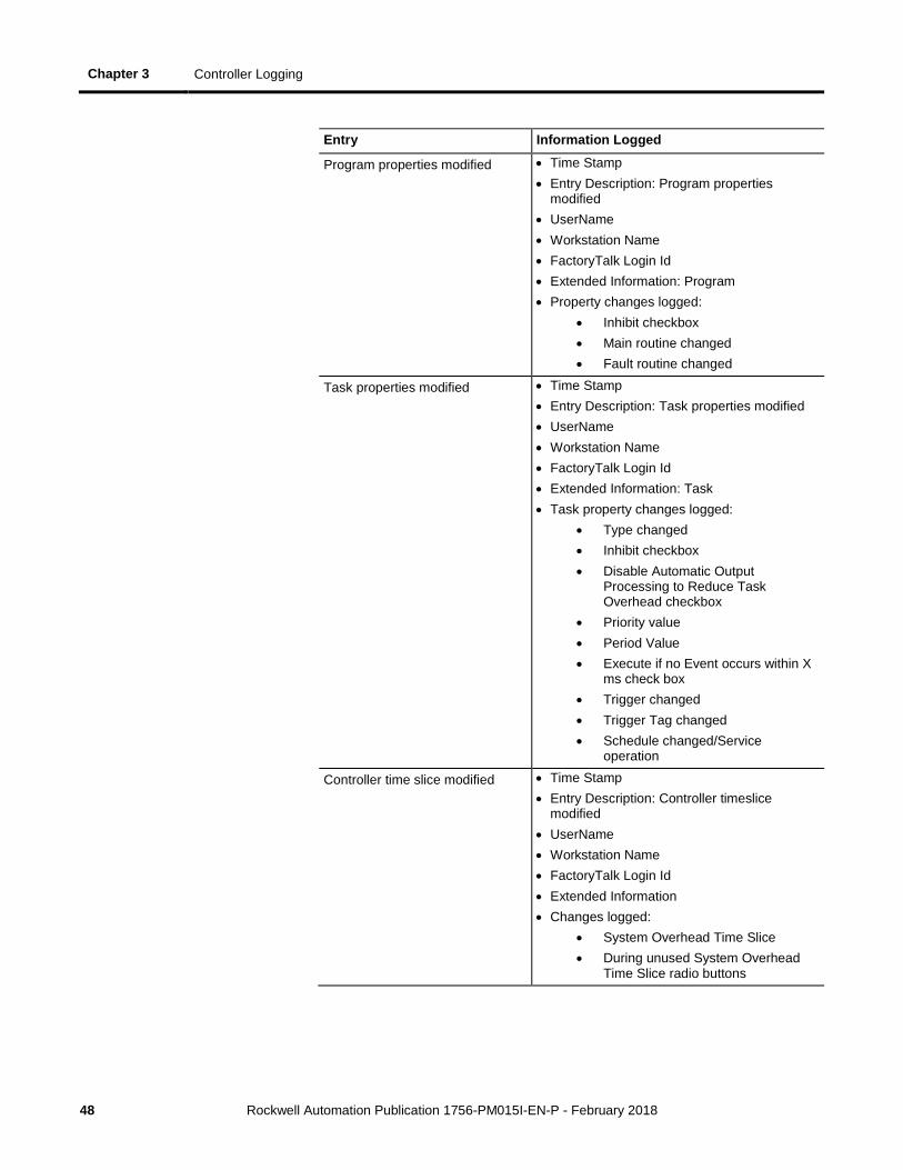
The following table describes the events that the controller stores in the controller log.
Tip: In Logix Designer versions 30 and later, audit log entries also appear in the controller log. Audit log entries describe events such as changes to component properties, edits in a routine, and changes to tag values. The audit log is used for auditing by the FactoryTalk® AssetCentre.
Entry Information Logged
Project download1 • Time Stamp • Entry Description: Project download • UserName • Workstation Name • FactoryTalk Login Id • Extended Information: Project
Load from removable media • Time Stamp • Entry Description: Project load • UserName • Workstation Name • FactoryTalk Login Id • Extended Information: Project
Load from removable media auto-initiated
• Time Stamp • Entry Description: Project auto load • UserName: Local • Workstation Name: None • FactoryTalk Login Id: None • Extended Information: Project
Store to removable media • Time Stamp • Entry Description: Project store • UserName • Workstation Name • FactoryTalk Login Id • Extended Information: Project
Sample Ladder Logic File
Controller Log Events
Controller Logging Chapter 3
Rockwell Automation Publication 1756-PM015I-EN-P - February 2018 45
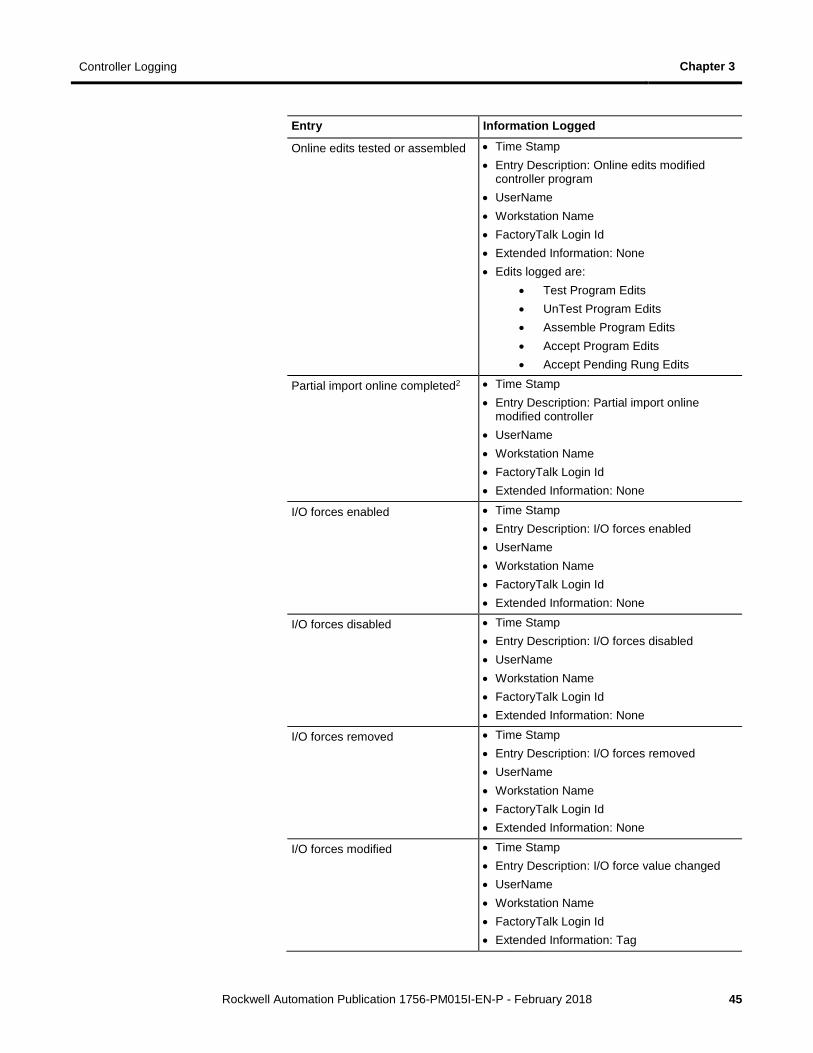
Entry Information Logged
Online edits tested or assembled • Time Stamp • Entry Description: Online edits modified
controller program • UserName • Workstation Name • FactoryTalk Login Id • Extended Information: None • Edits logged are:
• Test Program Edits • UnTest Program Edits • Assemble Program Edits • Accept Program Edits • Accept Pending Rung Edits
Partial import online completed2 • Time Stamp • Entry Description: Partial import online
modified controller • UserName • Workstation Name • FactoryTalk Login Id • Extended Information: None
I/O forces enabled • Time Stamp • Entry Description: I/O forces enabled • UserName • Workstation Name • FactoryTalk Login Id • Extended Information: None
I/O forces disabled • Time Stamp • Entry Description: I/O forces disabled • UserName • Workstation Name • FactoryTalk Login Id • Extended Information: None
I/O forces removed • Time Stamp • Entry Description: I/O forces removed • UserName • Workstation Name • FactoryTalk Login Id • Extended Information: None
I/O forces modified • Time Stamp • Entry Description: I/O force value changed • UserName • Workstation Name • FactoryTalk Login Id • Extended Information: Tag
Chapter 3 Controller Logging
46 Rockwell Automation Publication 1756-PM015I-EN-P - February 2018
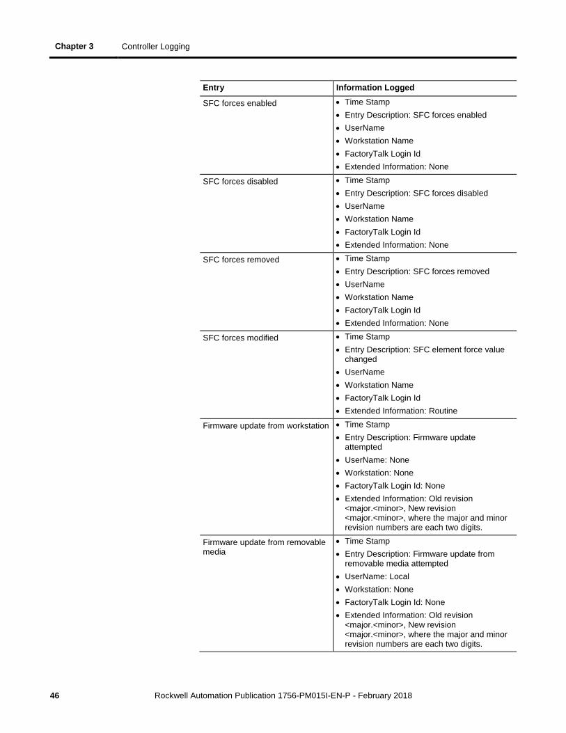
Entry Information Logged
SFC forces enabled • Time Stamp • Entry Description: SFC forces enabled • UserName • Workstation Name • FactoryTalk Login Id • Extended Information: None
SFC forces disabled • Time Stamp • Entry Description: SFC forces disabled • UserName • Workstation Name • FactoryTalk Login Id • Extended Information: None
SFC forces removed • Time Stamp • Entry Description: SFC forces removed • UserName • Workstation Name • FactoryTalk Login Id • Extended Information: None
SFC forces modified • Time Stamp • Entry Description: SFC element force value
changed • UserName • Workstation Name • FactoryTalk Login Id • Extended Information: Routine
Firmware update from workstation • Time Stamp • Entry Description: Firmware update
attempted • UserName: None • Workstation: None • FactoryTalk Login Id: None • Extended Information: Old revision
<major.<minor>, New revision <major.<minor>, where the major and minor revision numbers are each two digits.
Firmware update from removable media
• Time Stamp • Entry Description: Firmware update from
removable media attempted • UserName: Local • Workstation: None • FactoryTalk Login Id: None • Extended Information: Old revision
<major.<minor>, New revision <major.<minor>, where the major and minor revision numbers are each two digits.
Controller Logging Chapter 3
Rockwell Automation Publication 1756-PM015I-EN-P - February 2018 47
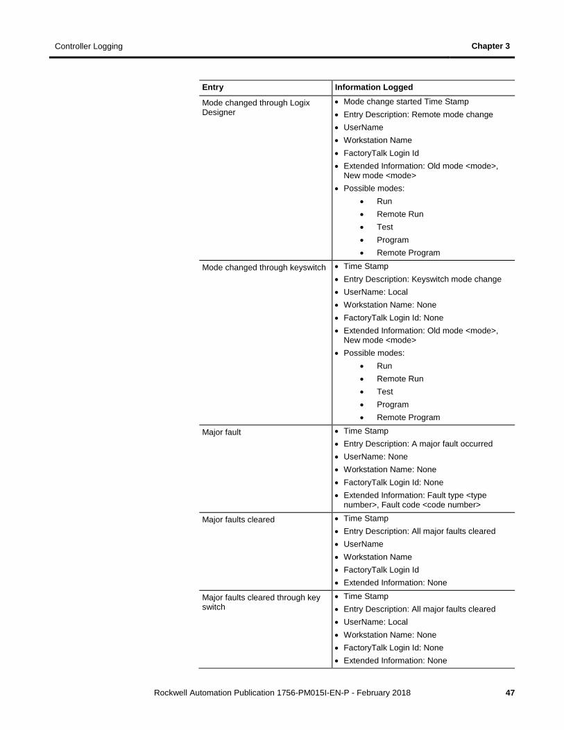
Entry Information Logged
Mode changed through Logix Designer
• Mode change started Time Stamp • Entry Description: Remote mode change • UserName • Workstation Name • FactoryTalk Login Id • Extended Information: Old mode <mode>,
New mode <mode> • Possible modes:
• Run • Remote Run • Test • Program • Remote Program
Mode changed through keyswitch • Time Stamp • Entry Description: Keyswitch mode change • UserName: Local • Workstation Name: None • FactoryTalk Login Id: None • Extended Information: Old mode <mode>,
New mode <mode> • Possible modes:
• Run • Remote Run • Test • Program • Remote Program
Major fault • Time Stamp • Entry Description: A major fault occurred • UserName: None • Workstation Name: None • FactoryTalk Login Id: None • Extended Information: Fault type <type
number>, Fault code <code number>
Major faults cleared • Time Stamp • Entry Description: All major faults cleared • UserName • Workstation Name • FactoryTalk Login Id • Extended Information: None
Major faults cleared through key switch
• Time Stamp • Entry Description: All major faults cleared • UserName: Local • Workstation Name: None • FactoryTalk Login Id: None • Extended Information: None
Chapter 3 Controller Logging
48 Rockwell Automation Publication 1756-PM015I-EN-P - February 2018
Entry Information Logged
Program properties modified • Time Stamp • Entry Description: Program properties
modified • UserName • Workstation Name • FactoryTalk Login Id • Extended Information: Program • Property changes logged:
• Inhibit checkbox • Main routine changed • Fault routine changed
Task properties modified • Time Stamp • Entry Description: Task properties modified • UserName • Workstation Name • FactoryTalk Login Id • Extended Information: Task • Task property changes logged:
• Type changed • Inhibit checkbox • Disable Automatic Output
Processing to Reduce Task Overhead checkbox
• Priority value • Period Value • Execute if no Event occurs within X
ms check box • Trigger changed • Trigger Tag changed • Schedule changed/Service
operation
Controller time slice modified • Time Stamp • Entry Description: Controller timeslice
modified • UserName • Workstation Name • FactoryTalk Login Id • Extended Information • Changes logged:
• System Overhead Time Slice • During unused System Overhead
Time Slice radio buttons
Controller Logging Chapter 3
Rockwell Automation Publication 1756-PM015I-EN-P - February 2018 49
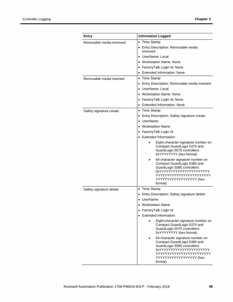
Entry Information Logged
Removable media removed • Time Stamp • Entry Description: Removable media
removed • UserName: Local • Workstation Name: None • FactoryTalk Login Id: None • Extended Information: None
Removable media inserted • Time Stamp • Entry Description: Removable media inserted • UserName: Local • Workstation Name: None • FactoryTalk Login Id: None • Extended Information: None
Safety signature create • Time Stamp • Entry Description: Safety signature create • UserName • Workstation Name • FactoryTalk Login Id • Extended Information:
• Eight-character signature number on Compact GuardLogix 5370 and GuardLogix 5570 controllers: 0xYYYYYYYY (hex format)
• 64-character signature number on Compact GuardLogix 5380 and GuardLogix 5580 controllers: 0xYYYYYYYYYYYYYYYYYYYYYYYYYYYYYYYYYYYYYYYYYYYYYYYYYYYYYYYYYYYYYYYY (hex format)
Safety signature delete • Time Stamp • Entry Description: Safety signature delete • UserName • Workstation Name • FactoryTalk Login Id • Extended Information:
• Eight-character signature number on Compact GuardLogix 5370 and GuardLogix 5570 controllers: 0xYYYYYYYY (hex format)
• 64-character signature number on Compact GuardLogix 5380 and GuardLogix 5580 controllers: 0xYYYYYYYYYYYYYYYYYYYYYYYYYYYYYYYYYYYYYYYYYYYYYYYYYYYYYYYYYYYYYYYY (hex format)
Chapter 3 Controller Logging
50 Rockwell Automation Publication 1756-PM015I-EN-P - February 2018
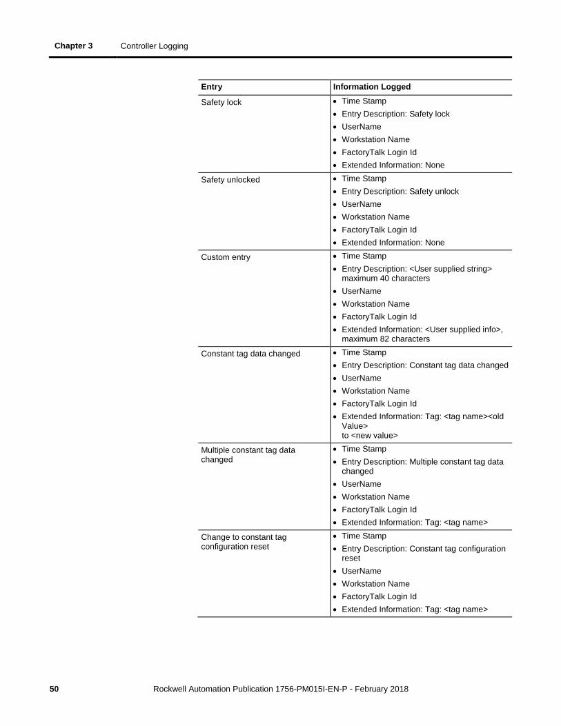
Entry Information Logged
Safety lock • Time Stamp • Entry Description: Safety lock • UserName • Workstation Name • FactoryTalk Login Id • Extended Information: None
Safety unlocked • Time Stamp • Entry Description: Safety unlock • UserName • Workstation Name • FactoryTalk Login Id • Extended Information: None
Custom entry • Time Stamp • Entry Description: <User supplied string>
maximum 40 characters • UserName • Workstation Name • FactoryTalk Login Id • Extended Information: <User supplied info>,
maximum 82 characters
Constant tag data changed • Time Stamp • Entry Description: Constant tag data changed • UserName • Workstation Name • FactoryTalk Login Id • Extended Information: Tag: <tag name><old
Value> to <new value>
Multiple constant tag data changed
• Time Stamp • Entry Description: Multiple constant tag data
changed • UserName • Workstation Name • FactoryTalk Login Id • Extended Information: Tag: <tag name>
Change to constant tag configuration reset
• Time Stamp • Entry Description: Constant tag configuration
reset • UserName • Workstation Name • FactoryTalk Login Id • Extended Information: Tag: <tag name>
Controller Logging Chapter 3
Rockwell Automation Publication 1756-PM015I-EN-P - February 2018 51
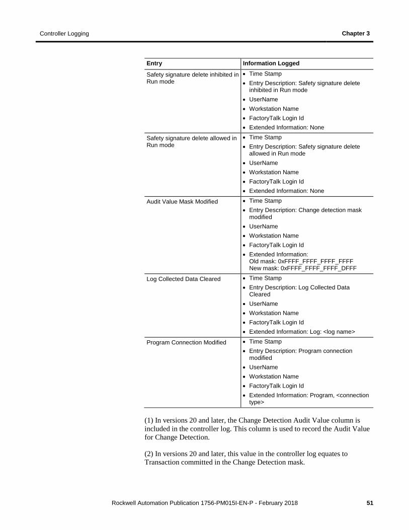
Entry Information Logged
Safety signature delete inhibited in Run mode
• Time Stamp • Entry Description: Safety signature delete
inhibited in Run mode • UserName • Workstation Name • FactoryTalk Login Id • Extended Information: None
Safety signature delete allowed in Run mode
• Time Stamp • Entry Description: Safety signature delete
allowed in Run mode • UserName • Workstation Name • FactoryTalk Login Id • Extended Information: None
Audit Value Mask Modified • Time Stamp • Entry Description: Change detection mask
modified • UserName • Workstation Name • FactoryTalk Login Id • Extended Information:
Old mask: 0xFFFF_FFFF_FFFF_FFFF New mask: 0xFFFF_FFFF_FFFF_DFFF
Log Collected Data Cleared • Time Stamp • Entry Description: Log Collected Data
Cleared • UserName • Workstation Name • FactoryTalk Login Id • Extended Information: Log: <log name>
Program Connection Modified • Time Stamp • Entry Description: Program connection
modified • UserName • Workstation Name • FactoryTalk Login Id • Extended Information: Program, <connection
type>
(1) In versions 20 and later, the Change Detection Audit Value column is included in the controller log. This column is used to record the Audit Value for Change Detection.
(2) In versions 20 and later, this value in the controller log equates to Transaction committed in the Change Detection mask.

Chapter 3 Controller Logging
52 Rockwell Automation Publication 1756-PM015I-EN-P - February 2018
Rockwell Automation Publication 1756-PM015I-EN-P - February 2018 53
Chapter 4
Change Detection
You can use the controller change detection feature as an additional means of detecting changes made to Logix5000 controllers.
• A unique audit value is generated when a project is downloaded to the controller.
• When a change is detected in the controller, a new audit value is generated.
• ChangesToDetect mask allows you to programmatically configure the events to monitor for changes.
• Controller change detection is integrated into the Logix Designer application.
Important: The change detection feature is not supported in version 19 or earlier.
Note the following considerations for change detection.
• Change detection is not available on the Studio 5000® Logix Emulate™ Controller and the SoftLogix5860 Controller, and the audit value is not populated.
• The 1769-L3x and 1769-L4x CompactLogix controllers do not support storing log entries to removable media.
• Change detection is integrated in FactoryTalk AssetCentre version 4.1 and later. FactoryTalk AssetCentre can be configured to detect changes in the controller and read the controller's Controller Log.
• Change detection is not integrated with RSMACC utilities.
Two controller attributes support the Change Detection feature in version 20 and later.
Attribute Name Description Access
AuditValue A unique value that is generated when a project is downloaded to the controller or loaded from removable storage. When a change is detected this value is updated. To specify which changes are monitored, use the ChangesToDetect attribute.
GSV
ChangesToDetect Used to specify which changes are monitored. When a monitored change occurs, the Audit Value is updated.
GSV/SSV
Introduction
Controller Change Detection
Chapter 4 Change Detection
54 Rockwell Automation Publication 1756-PM015I-EN-P - February 2018
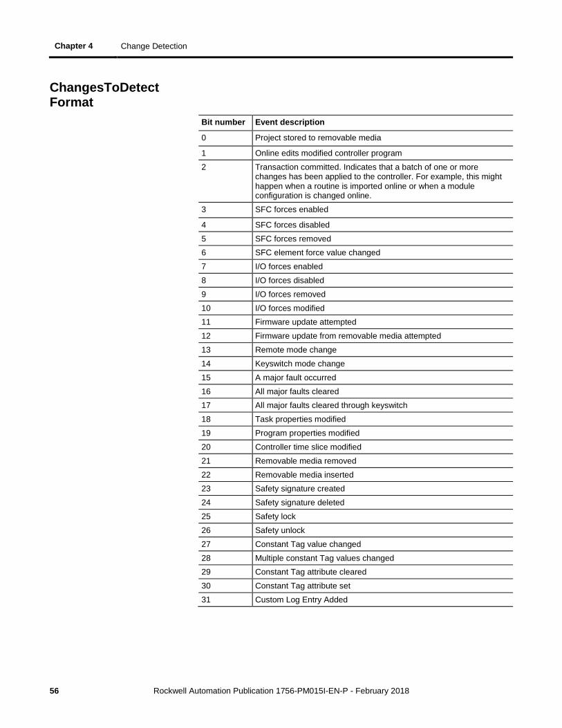
The ChangesToDetect mask is a 64-bit value. Each bit of the ChangesToDetect mask corresponds to a particular event that could cause the Audit Value to change. See ChangesToDetect Format on page 56.
Important: Change detection is unavailable on the Studio 5000 Logix Emulate Controller and the SoftLogix5860 Controller.
If a bit is set to a value of 1, the corresponding event is monitored for changes and when a change for that event occurs the AuditValue updates. If a bit is set to a value of 2, the corresponding event is not monitored and does not affect the Audit Value. The default Audit Value of: 0xFFFFFFFFFFFFFFFF indicates that all events are monitored.
Tip: The Audit Value updates when the controller is online.
Some events always update the audit value when they occur. For example, the audit value changes when a project is downloaded to the controller, or when ChangesToDetect is reconfigured. These types of events are not included in the ChangesToDetect mask.
You can configure the ChangesToDetect mask programmatically using SSV, GSV and MSG instructions.
Tip: You can use the Security tab in the Controller Properties dialog box to configure Change Detection if you are using version 20 or later of the application. See Change Detection in Logix Designer Application on page 57.
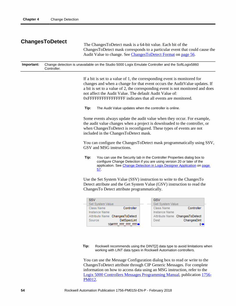
Use the Set System Value (SSV) instruction to write to the ChangesTo Detect attribute and the Get System Value (GSV) instruction to read the ChangesTo Detect attribute programmatically.
Tip: Rockwell recommends using the DINT[2] data type to avoid limitations when working with LINT data types in Rockwell Automation controllers.
You can use the Message Configuration dialog box to read or write to the ChangesToDetect attribute through CIP Generic Messages. For complete information on how to access data using an MSG instruction, refer to the Logix 5000 Controllers Messages Programming Manual, publication 1756-PM012.
ChangesToDetect
Change Detection Chapter 4
Rockwell Automation Publication 1756-PM015I-EN-P - February 2018 55
Use the following settings to configure the ChangesToDetect attribute using the Message Configuration dialog box.
If you want to: In this property Type or select
Set controller events monitored for changes
Message Type CIP Generic
Service Type Changes to Detect Set
Source tag_name of type DINT[2] or LINT 1 This tag represents a bit mask of the changes monitored for the controller.
Destination Leave blank
Get controller events monitored for changes
Message Type CIP Generic
Service Type Changes to Detect Get
Source Leave blank Destination tag_name of type DINT[2] or LINT 1
This tag represents a bit mask of the changes monitored for the controller.
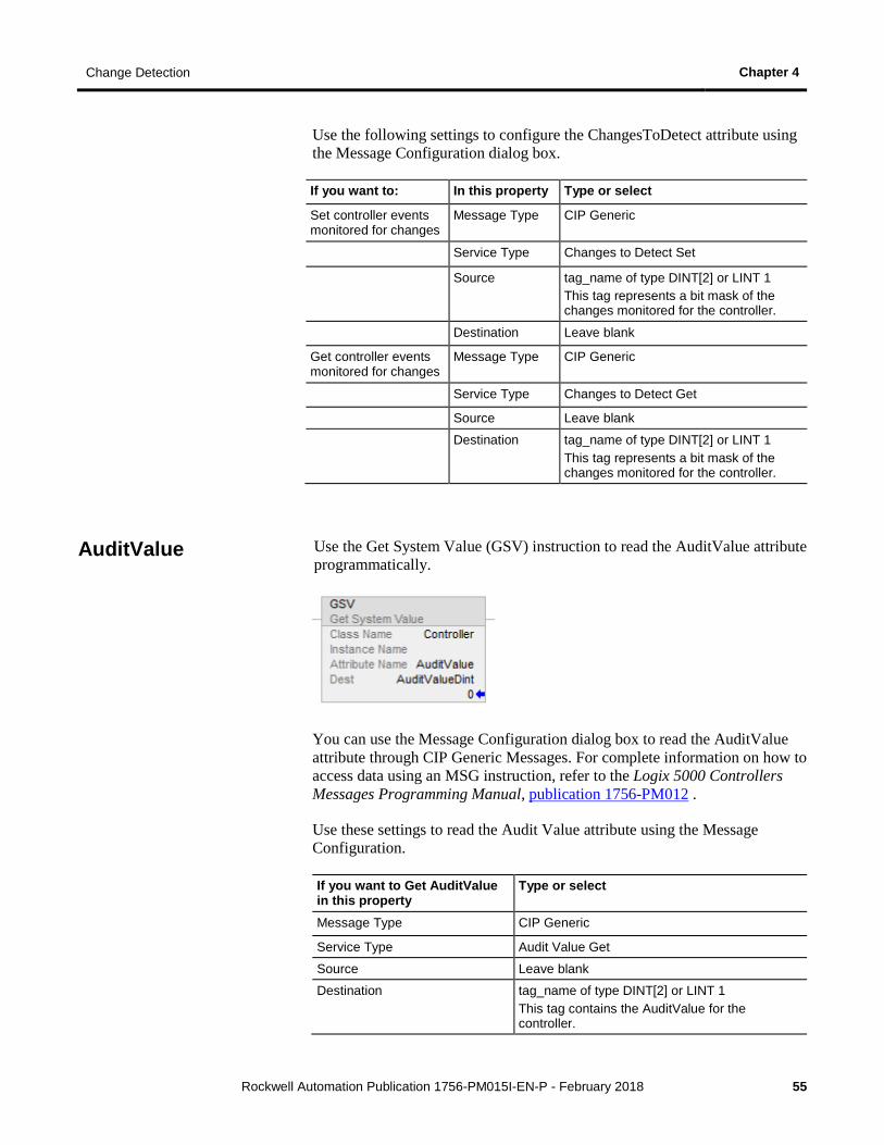
Use the Get System Value (GSV) instruction to read the AuditValue attribute programmatically.
You can use the Message Configuration dialog box to read the AuditValue attribute through CIP Generic Messages. For complete information on how to access data using an MSG instruction, refer to the Logix 5000 Controllers Messages Programming Manual, publication 1756-PM012 .
Use these settings to read the Audit Value attribute using the Message Configuration.
If you want to Get AuditValue in this property
Type or select
Message Type CIP Generic
Service Type Audit Value Get
Source Leave blank
Destination tag_name of type DINT[2] or LINT 1 This tag contains the AuditValue for the controller.
AuditValue
Chapter 4 Change Detection
56 Rockwell Automation Publication 1756-PM015I-EN-P - February 2018
Bit number Event description
0 Project stored to removable media
1 Online edits modified controller program
2 Transaction committed. Indicates that a batch of one or more changes has been applied to the controller. For example, this might happen when a routine is imported online or when a module configuration is changed online.
3 SFC forces enabled
4 SFC forces disabled
5 SFC forces removed
6 SFC element force value changed
7 I/O forces enabled
8 I/O forces disabled
9 I/O forces removed
10 I/O forces modified
11 Firmware update attempted
12 Firmware update from removable media attempted
13 Remote mode change
14 Keyswitch mode change
15 A major fault occurred
16 All major faults cleared
17 All major faults cleared through keyswitch
18 Task properties modified
19 Program properties modified
20 Controller time slice modified
21 Removable media removed
22 Removable media inserted
23 Safety signature created
24 Safety signature deleted
25 Safety lock
26 Safety unlock
27 Constant Tag value changed
28 Multiple constant Tag values changed
29 Constant Tag attribute cleared
30 Constant Tag attribute set
31 Custom Log Entry Added
ChangesToDetect Format
Change Detection Chapter 4
Rockwell Automation Publication 1756-PM015I-EN-P - February 2018 57
Bit number Event description
32 Correlation Affected. Indicates a change occurred in the controller that affects the synchronization between the controller and the project file that was downloaded to it.
Tip: Correlation Affected can include detection of a component that has been created, deleted, or modified, or logic that has been modified. Including the Correlation Affected event updates the audit value for these types of changes, even if other similar events (such as Online edits modified controller program or Task properties modified) are masked.
33 Safety signature delete inhibited in Run mode
34 Safety signature delete allowed in Run mode
35 Data log or Alarm log cleared
36 Program connection modified
You use the Security tab in the Controller Properties dialog box (available in version 20 and later of the application) to configure Change Detection.
To edit the Changes To Detect field, type a new value. To select the events to monitor for changes from a list, click Configure to open the Configure Changes to Detect dialog box.
Change Detection in the Logix Designer Application
Chapter 4 Change Detection
58 Rockwell Automation Publication 1756-PM015I-EN-P - February 2018
For additional information on configuring the settings on the Security tab, refer to the Logix 5000 Security Programming Manual, publication 1756-PM016 or the online help for the Logix Designer application.
Tip: To configure Change Detection programmatically use SSV, GSV or MSG instructions. See Controller Change Detection on page 53.
Use component tracking to determine whether tracked components have been changed. Like change detection, component tracking indicates changes to a project, but at the component level. The Logix Designer application creates a unique signature for each tracked component and compiles those signatures into one overall tracked value to indicate their current state. The following components can be tracked:
• Routines
• Add-On Instructions
• I/O Modules
• Constant tags
Tip: Component tracking is supported only on CompactLogix 5370, ControlLogix 5570, Compact GuardLogix 5370, and GuardLogix 5570 controllers in version 30 of the Logix Designer application.
Tracked components appear in the Tracked Components dialog box, which is accessible on the Controller Properties dialog box - Security tab. The tracked value changes when a tracked component is updated in a way that affects the execution of a routine or an Add-On Instruction. Updating a component attribute that does not affect execution--for example, descriptions and non-constant tag values--does not change the tracked value.
Tip: When an attribute is changed and then changed back to its previous value, the tracked value does not change. This behavior differs from Change Detection, which registers a change even when the change is reversed.
Tip: The Tracked State value and the list of tracked components are static as long as the dialog box is open and will not reflect changes from other workstations. If a user on another workstation makes an update, you might need to close and re-open the Tracked Components dialog box to see the changes.
Recommended limits for tracked components
The following table lists the recommended limits on the number of components that can be tracked. If the limits are exceeded, there might be a noticeable impact on performance in the Logix Designer application.
Tip: To optimize performance, configure component tracking so that the tracked state value is calculated on demand rather than at regular intervals.
Tracked component Recommended limit
Routines 100 Add-On Instructions 100
Component tracking
Change Detection Chapter 4
Rockwell Automation Publication 1756-PM015I-EN-P - February 2018 59
I/O Modules 50
Tags 300
FactoryTalk Security permissions that control component tracking
The following FactoryTalk Security permissions control a user's ability to change tracking status for a component:
• Routine: Modify Properties
• Add-On Instruction: Modify
• Module: Modify Properties
• Tag: Modify Properties
Designate project components for tracking to monitor the current state of a component. Use the following instructions to track the state of a routine, an Add-On Instruction, an I/O module, or a constant tag.
To track the state of a component:
1. In the Controller Organizer, highlight the component to track.
2. Right-click and select Include in tracking group.
3. To stop tracking a component, right-click and select Include in tracking group again.
Tip: If you plan to use the tracked state value to verify that code in a tracked routine is being executed, make sure to track all the routines that call the tracked routine, up to and including the main routine. If you do not track all components that call the tracked routine, a user could modify the project so that the tracked routine is no longer called.
To track the state of a constant tag:
1. In the Tag editor or the Data Monitor, highlight the constant tag to track.
2. Right-click and select Include in tracking group.
3. To stop tracking a constant tag, right-click and select Include in tracking group again.
Tip: When you track a base tag or an alias tag, the base tag and all alias tags are tracked.
Track the state of components and constant tags
Chapter 4 Change Detection
60 Rockwell Automation Publication 1756-PM015I-EN-P - February 2018
After you select project components for tracking, you can check project component status in the Tracked Components dialog box, which is accessible on the Controller Properties dialog box - Security tab.
To view tracked components:
1. On the Online toolbar, click the Controller Properties icon.
2. On the Controller Properties dialog box, click the Security tab.
3. In the Change Detection section, click View components to open the Tracked components dialog box.
Use a Message (MSG) instruction to retrieve the tracked state value. When the controller receives the MSG instruction, it calculates the tracked state value and stores it in a destination tag.
Tip: If you plan to use the tracked state value to verify that code in a tracked routine is being executed, make sure to track all the routines that call the tracked routine, up to and including the main routine. If you do not track all components that call the tracked routine, a user could modify the project so that the tracked routine is no longer called.
To retrieve the tracked state value using an MSG instruction:
1. Create a MESSAGE tag.
2. Insert an MSG instruction in your ladder logic or Structured Text routine.
3. In the instruction, click Browse to open the Message Configuration dialog box.
4. On the Configuration tab, configure the following settings:
• For Message Type, select CIP Generic.
• For Service Type, select Tracked State Value Get.
• For Source Element, select the source tag element. In this release of Logix Designer, the value of the SINT datatype must be 1.
• For Destination Element, select the tag where the controller sends the tracked state value. For best results, create a destination tag that is an array of 32 SINTs.
5. On the Communication tab, configure the communication path.
6. Click Apply.
View tracked components
Retrieve the tracked state value using a Message instruction

Change Detection Chapter 4
Rockwell Automation Publication 1756-PM015I-EN-P - February 2018 61

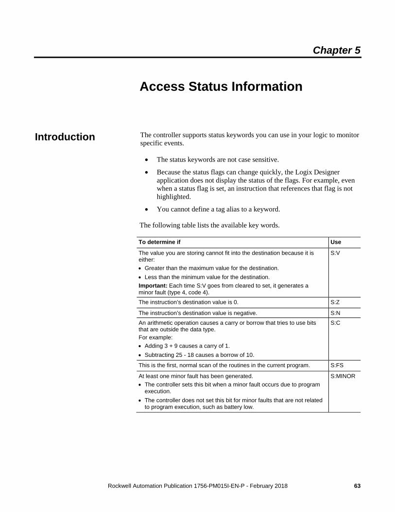
Rockwell Automation Publication 1756-PM015I-EN-P - February 2018 63
Chapter 5
Access Status Information
The controller supports status keywords you can use in your logic to monitor specific events.
• The status keywords are not case sensitive.
• Because the status flags can change quickly, the Logix Designer application does not display the status of the flags. For example, even when a status flag is set, an instruction that references that flag is not highlighted.
• You cannot define a tag alias to a keyword.
The following table lists the available key words.
To determine if Use
The value you are storing cannot fit into the destination because it is either: • Greater than the maximum value for the destination. • Less than the minimum value for the destination. Important: Each time S:V goes from cleared to set, it generates a minor fault (type 4, code 4).
S:V
The instruction’s destination value is 0. S:Z
The instruction’s destination value is negative. S:N
An arithmetic operation causes a carry or borrow that tries to use bits that are outside the data type. For example: • Adding 3 + 9 causes a carry of 1. • Subtracting 25 - 18 causes a borrow of 10.
S:C
This is the first, normal scan of the routines in the current program. S:FS
At least one minor fault has been generated. • The controller sets this bit when a minor fault occurs due to program
execution. • The controller does not set this bit for minor faults that are not related
to program execution, such as battery low.
S:MINOR
Introduction
Chapter 5 Access Status Information
64 Rockwell Automation Publication 1756-PM015I-EN-P - February 2018
The state of S:FS depends on the status of the SFC.
• If you use S:FS in an action of a sequential function chart (SFC), S:FS is set (on) for one scan each time the step goes active. S:FS = step_name.FS.
• If the SFC calls a routine, S:FS is set (on) for one scan each time the step that calls the routine goes active. S:FS = step_name.FS.
If the SFC does not call a routine, S:FS is set (on) for the first scan of the task.
Example: SFC Calls a Ladder Diagram Suppose several steps in an SFC call the same ladder diagram routine. And suppose the ladder diagram uses S:FS. Each time one of those steps goes active, S:FS turns on for one scan of the ladder diagram.
Example: Several Tasks but No SFC Suppose you have two tasks that use ladder diagrams. When the first task runs for the first time, S:FS turns on for one scan. After that, S:FS stays off for that task. When the other task runs for the first time, S:FS turns on for one scan in that task. S:FS stays off in the first task that ran.
The controller stores system data in objects. There is no status file, as in the PLC-5 controller. Use the GSV/SSV instructions to get and set controller system data that is stored in objects.
• The GSV instruction retrieves the specified information and places it in the destination.
• The SSV instruction sets the specified attribute with data from the source.
Use the SSV instruction carefully. Making changes to objects can cause unexpected controller operation or injury to personnel.
To create a GSV/SSV instruction, you need to use Logix Designer online help to find the required information, and create the instruction in Logix Designer application. The following summary describes the steps.
• Open the online help in Logix Designer application to find the object and data type to use in the GSV/SSV instruction.
• In the Logix Designer application, create a tag for the value of the attribute.
• In the Ladder Logic editor, create the GSV/SSV instruction.
Use the following steps to get or set a system value.
1. Open the project in Logix Designer application.
2. From the Help menu, choose Contents.
Status of S:FS When the Project Has an SFC
Get and Set System Data
Access Status Information Chapter 5
Rockwell Automation Publication 1756-PM015I-EN-P - February 2018 65
3. On the Help window, click the Index tab.
4. In the Type in the keyword to find field, type GSV/SSV objects and click Display.
5. In the GSV/SSV Objects help window, click the object you need.
To get or set Select this object
Customize instructions for commonly-used logic
AddOnInstructionDefinition
Different Axis objects depending on motion application
Axis (Several types)
System-overhead time slice Controller
Physical hardware of a controller ControllerDevice
Groups one or more axes to generate coordinated motion
CoordinateSystem
Coordinated system time for the devices in one chassis
CST
DF1 communication driver for the serial port
DF1
Fault history for a controller FaultLog
Attributes of a message instruction
Message
Sttus, faults, and mode of a module
Module
Group of axes MotionGroup
Fault information or scan time for a program
Program
Instance number of a routine Routine
Different objects for safety Safety
Configuration of the serial port SerialPort
Properties or elapsed time of a task
Task
Precision time management for motion control
TimeSynchronize
Wall clock time of a controller WallClockTime
6. In the list of attributes for the object, identify the attribute that you want to access.
For attribute information, see the Logix 5000 Controllers General Instruction Reference Manual, publication 1756-RM003 .
7. In Logix Designer application, create a tag for the value of the attribute.
If the data type of the attribute is
Then
One element (for example, DINT) Create a tag for the attribute.
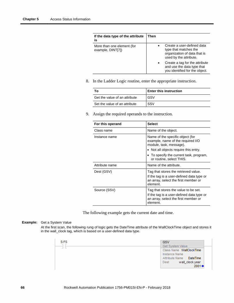
Chapter 5 Access Status Information
66 Rockwell Automation Publication 1756-PM015I-EN-P - February 2018
If the data type of the attribute is
Then
More than one element (for example, DINT[7])
• Create a user-defined data type that matches the organization of data that is used by the attribute.
• Create a tag for the attribute and use the data type that you identified for the object.
8. In the Ladder Logic routine, enter the appropriate instruction.
To Enter this instruction
Get the value of an attribute GSV
Set the value of an attribute SSV
9. Assign the required operands to the instruction.
For this operand Select
Class name Name of the object.
Instance name Name of the specific object (for example, name of the required I/O module, task, message). • Not all objects require this entry. • To specify the current task, program,
or routine, select THIS.
Attribute name Name of the attribute.
Dest (GSV) Tag that stores the retrieved value. If the tag is a user-defined data type or an array, select the first member or element.
Source (SSV) Tag that stores the value to be set. If the tag is a user-defined data type or an array, select the first member or element.
The following example gets the current date and time.
Example: Get a System Value At the first scan, the following rung of logic gets the DateTime attribute of the WallClockTime object and stores it in the wall_clock tag, which is based on a user-defined data type.

Access Status Information Chapter 5
Rockwell Automation Publication 1756-PM015I-EN-P - February 2018 67
For more GSV/SSV information, see the Logix 5000 Controllers General Instructions Reference Manual, publication 1756-RM003 .

Rockwell Automation Publication 1756-PM015I-EN-P - February 2018 69
A access
status information 63 AuditValue 55
B bridge
module connection 12
C Change Detection 53 ChangesToDetect 54 communicate
other controllers 11 CompactFlash
log 32 Component tracking 58 configure
I/O module 12 connection
failure 13 fault checkbox 14 I/O fault 13 inhibit 12 major fault 14 monitor 15
controller log entries 29 memory information 19
D DINT 26
F fault
communication loss 13 I/O connection 13
file log 41
G GSV/SSV
objects 64
I I/O module
communication loss 13 connection fault 13 inhibit 12 path configuration 11
inhibit attention symbol 12 connetion 12 I/O module 12 ladder logic 12
INT 26
L ladder
sample log file 43 log
CompactFlash card 32 counters 35 custom entries 42 entries 31 file format 41 file location 40 header 30 memory buffer 32 modification count 37 sample ladder file 43
M memory
determine amount 19 estimate free amount 21 run message instruction 24 types 19 view controller usage 22
monitor I/O connection 15
Index
Index
70 Rockwell Automation Publication 1756-PM015I-EN-P - February 2018
O objects
data storage 64
P path
connection route 11
S status
access data 63 memory 19 monitor 64
system data access 64
T Track components 58
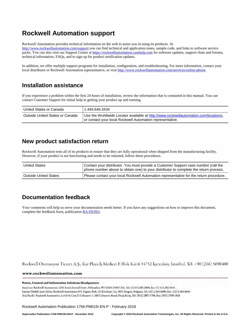
Rockwell Automation Publication 1756-PM015I-EN-P - February 2018
Supersedes Publication 1756-PM015H-EN-P - December 2016 Copyright © 2018 Rockwell Automation Technologies, Inc. All Rights Reserved. Printed in the U.S.A.
Rockwell Automation support Rockwell Automation provides technical information on the web to assist you in using its products. At http://www.rockwellautomation.com/support you can find technical and application notes, sample code, and links to software service packs. You can also visit our Support Center at https://rockwellautomation.custhelp.com for software updates, support chats and forums, technical information, FAQs, and to sign up for product notification updates.
In addition, we offer multiple support programs for installation, configuration, and troubleshooting. For more information, contact your local distributor or Rockwell Automation representative, or visit http://www.rockwellautomation.com/services/online-phone.
Installation assistance If you experience a problem within the first 24 hours of installation, review the information that is contained in this manual. You can contact Customer Support for initial help in getting your product up and running.
United States or Canada 1.440.646.3434 Outside United States or Canada Use the Worldwide Locator available at http://www.rockwellautomation.com/locations,
or contact your local Rockwell Automation representative.
New product satisfaction return Rockwell Automation tests all of its products to ensure that they are fully operational when shipped from the manufacturing facility. However, if your product is not functioning and needs to be returned, follow these procedures.
United States Contact your distributor. You must provide a Customer Support case number (call the phone number above to obtain one) to your distributor to complete the return process.
Outside United States Please contact your local Rockwell Automation representative for the return procedure.
Documentation feedback Your comments will help us serve your documentation needs better. If you have any suggestions on how to improve this document, complete the feedback form, publication RA-DU002.


