Download - Leeds & Northrup
Leeds & Northrup Company
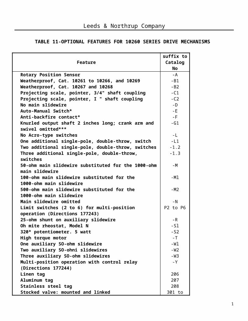
TABLE 11-OPTIONAL FEATURES FOR 10260 SERIES DRIVE MECHANISMS
Feature suffix toCatalog No
Rotary Position Sensor -AWeatherproof, Cat. 10261 to 10266, and 10269 -B1Weatherproof, Cat. 10267 and 10268 -B2Projecting scale, pointer, 3/4" shaft coupling -C1Projecting scale, pointer, I " shaft coupling -C2No main slidewire -DAuto-Manual Switch* -EAnti-backfire contact* -FKnurled output shaft 2 inches long; crank arm and swivel omitted*** -G1No Acro-type switches -LOne additional single-pole, double-throw, switch -L1Two additional single-pole, double-throw, switches -1.2Three additional single-pole, double-throw, switches -1.350-ohm main slidewire substituted for the 1000-ohm main slidewire -M100-ohm main slidewire substituted for the 1000-ohm main slidewire -Ml500-ohm main slidewire substituted for the 1000-ohm main slidewire -M2Main slidewire omitted -NLimit switches (2 to 6) for multi-position operation (Directions 177243) P2 to P625-ohm shunt on auxiliary slidewire -ROh mite rheostat, Model N -Sl320* potentiometer. 5 watt -S2High torque motor -TOne auxiliary SO-ohm slidewire -WlTwo auxiliary SO-ohni slidewires -W2Three auxiliary SO-ohm slidewires -W3Multi-position operation with control relay (Directions 177244) -YLinen tag 206Aluminum tag 207Stainless steel tag 208Stocked valve: mounted and linked 301 to 308
* Permits local electrical operation of drive unit during installation, process start-up, or anytime local manual process control is required. Applicable only to 10261,10262,10264,10266,10268, including suffix combination N-L2. Not available with suffixes A, L3, PC3, POY, W2, W3, or combination S2-Wl.
** The anti-backfire contact is a stationary short across that end of the control slidewire (whose feedback signal determines the setting of the fuel control valve) that corresponds to the closed position of the fuel valve. Thus, if the fuel valve is closing, the anti-backfire contact causes the drive mechanism to close the fuel valve completely before the burner backfirepoint is reached, thereby avoiding the danger.
*** Standard 2 " long shaft on 10263, 10265, and 10269. On all other units, where the -G 1 suffix is not specified, the output shaft is 1-1/2" long. Refer to outline and dimension dwg. in this book.
Leeds & Northrup Company
1

The mechanism is shipped with three plugs mounted in the top cover as shown in Fig.
1. After the mechanism is installed, remove the plug in the uppermost position and mount the
breather plug, which is furnished separately with the mechanism, in its place. This locates
the breather plug above the level of the lubricant in the worm gear compartment. If the
mechanism is mounted with its base down, remove any one of the three plugs, preferably the
one in the middle. Note that the breather plug functions to prevent the formation of an
atmospheric block in the lubricant-filled worm-gear compartment.
All units with the S2 option: do not turn the handwheel beyond the 0 and 100
calibration limits indicated by the output shaft pointer. Otherwise the 320* potentiometer may
be damaged.
3B. Linkage
(1) General Information
For many applications, the controlled device (final control element) will not provide
linear regulation of the controlled quantity throughout its range of travel. A butterfly valve,
damper, or similar device, will normally have the characteristic relationship between position
and flow, as illustrated by the solid line in Fig. 2, where a valve is the controlled device.
Leeds & Northrup Company
2

A non-linear toggle linkage can provide small increments of travel of the controlled
device in the lower portion of its range and greater increments of travel in the upper portion
of its range for equal increments of drive mechanism travel, as illustrated in Fig. 3. Thus,
when toggle linkage is properly applied, it will tend to linearize the characteristic of the
controlled device as illustrated by the dotted line in Fig. 2.
To install the linkage, it may be necessary to reposition the crank arm of the drive unit
on the output shaft. To do this, loosen the clamp screw in the crank arm. After repositioning
the crank arm, torque the bolt and nut to 40-45 lb. -ft.*, with antiseize compound applied to t
he threads. After the linkage has been installed, position the pointer on the output shaft so
that it indicates 0 to 100 on the scale as the crank arm moves between its limits of travel.
Lubricate the swivels of the linkage.
The swivel assembly can be positioned at any point along the slot in the crank arm.
Thus, the effective length of the crank arm can be adjusted to a maximum of 4-7/8 inches. To
reposition the swivel assembly, simply loosen the swivel stud, slide the assembly to the
desired position, and then retighten the stud; torque to 30-35 lb. -ft. Be certain to lubricate the
swivel, stud, and all other linkage pins.
In many cases, the output shaft of the drive
mechanism is arranged to rotate in a clockwise direction to
close the valve (driven device). However, a check should
be made to determine which direction the output shaft does
rotate to close the valve (driven device) and then refer to
the proper linkage diagram.
Fig. 3-Characteristic curve for a non-linear toggle linkage operation of a valve
*75 lb-ft: on 10263, 10265, 10269, and all units with the 12" crank arm or 165 lb-ft for the 11261-C6 crank
arm.
Leeds & Northrup Company
3

(2) Linkage with Toggle Action
Fig. 4 illustrates linkage for four different operating positions of the controlled device,
in this case a valve.
Fig. 4-Four different positions ot controlled device sing linkage with toggle action.
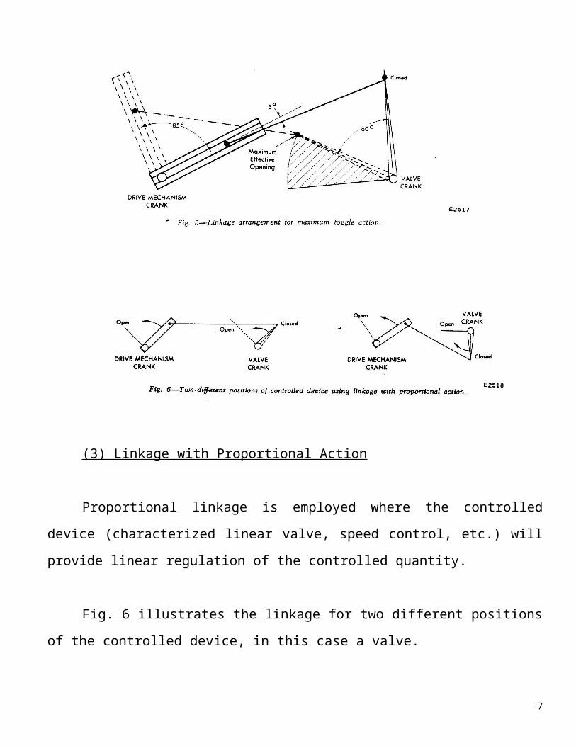
Maximum toggle action is obtained when the drive mechanism crank arm and link rod
are within 5o of dead center at the time when the con -trolled device crank arm and link rod
approach a 90 o angle. This is illustrated in Fig. 5 in which a valve is shown as the controlled
device. It is to be noted that the drive mechanism crank arm moves through only 85o , since
that is the limit of movement of the control slidewire. Reduced toggle effect is obtained when
the drive mechanism crank arm link rod angle is increased through the range of 5 o to
approximately 30 o .
The process should be tested to insure that the controlled device is effective through
the entire range of drive mechanism travel, as illustrated in Fig. 5, and the link rod length
adjusted accordingly. Note that with toggle action, it is particularly important that the limit
switches be set properly to avoid damaging valve seats and possibly the drive unit itself, by
exceeding the overhung load rating. A suggested test procedure is outlined in Section 3E.
Leeds & Northrup Company
4

(3) Linkage with Proportional Action
Proportional linkage is employed where the controlled device (characterized linear
valve, speed control, etc.) will provide linear regulation of the controlled quantity.
Fig. 6 illustrates the linkage for two different positions of the controlled device, in this
case a valve.
Leeds & Northrup Company
(4) Linkage for Fuel-Air Ratio Control
5

When a process includes control of fuel from temperature, and proportioning of air
flow by means of a fuel-air ratio controller, special attention must be given to arrangement of
valve or damper linkages to provide proper functioning of the entire system.
Since fuel flow will be directly proportional to temperature change, the fuel control
valve should be linearized either through the use of a characterized (linear) valve or by
providing toggle action (as outlined in Section 3B2) in the fuel control valve linkage.
Conversely, since the air control valve drive unit will respond to a linear relation
between fuel flow differential and -air flow differential (thus to fuel flow squared) the air'
control valve must be moved faster in the lower end of its range and slower in the upper end
of its range to match the speed of response of the oil valve control.
An inverse toggle action, illustrated in Fig. 7, applied to the air control valve, will
provide the desired response characteristic.
6
Leeds & Northrup Company
For those installations where air flow is controlled from temperature and fuel is controlled by fuel-air ratio, the air control valve should be linearized, and the fuel ontrol valve will require inverse toggle linkage.
3C. Limit Switches
The limit switch cams, Fig. 8, are adjusted at the factory to operate at the extremes of
the indicating scale (85o travel of the operating crank) and normally need not be changed in
the field.
7


