Download - IWS Sample QandA Examinations

Page 1 of 23Rev 1
INTERNATIONAL WELDING SPECIALIST (IWS)INCORPORATING WTIA WELDING SUPERVISOR
AS 1796 CERTIFICATE 10 AND AS 2214WELDING SUPERVISOR
AND
INTERNATIONAL WELDING INSPECTIONPERSONNEL STANDARD (IWI S)
INCORPORATINGWTIA WELDING INSPECTOR
SAMPLEQUESTIONS AND ANSWERS
BANK
Page 2 of 23Rev 1
QUESTION 1
1.1 State five functions of the flux in the flux cored arc welding process. 5 marks (Ref: 1.8)
• Stabilise the arc• Shield molten metal from atmosphere• Scavenge impurities• Controls shape and appearance of weld• Adjusts chemical composition of weld
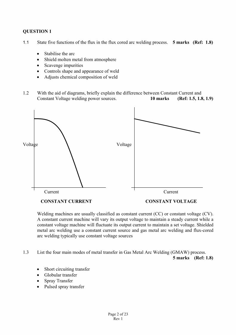
1.2 With the aid of diagrams, briefly explain the difference between Constant Current andConstant Voltage welding power sources. 10 marks (Ref: 1.5, 1.8, 1.9)
Voltage Voltage
Current Current
CONSTANT CURRENT CONSTANT VOLTAGE
Welding machines are usually classified as constant current (CC) or constant voltage (CV).A constant current machine will vary its output voltage to maintain a steady current while aconstant voltage machine will fluctuate its output current to maintain a set voltage. Shieldedmetal arc welding use a constant current source and gas metal arc welding and flux-coredarc welding typically use constant voltage sources
1.3 List the four main modes of metal transfer in Gas Metal Arc Welding (GMAW) process. 5 marks (Ref: 1.8)
• Short circuiting transfer• Globular transfer• Spray Transfer• Pulsed spray transfer
Page 3 of 23Rev 1
QUESTION 2
2.1 List three reasons why SAW solid wires are copper coated. 5 marks (Ref: 1.10)
• It improves the current pickup between contact tip and the electrode.• It aids in the drawing process• Helps prevent rusting of the wire when it is exposed to the atmosphere.
2.2 What is “twin wire” (tandem wire) GMAW? What are the two variations in the weldingprocess? 8 marks (Ref: 1.8)
Automated GMAW process with two wires under one shielding gas nozzle. The tips areinsulated from one another and connected to their own wire feeder and power source andregulated by electronic control system. Welding current may be pulsed or non-pulsed. Thelead wire generates the required penetration while the trail wire provides additional jointfilling as well as an excellent weld profile.
Variation 1: The lead wire uses non-pulsed current, while the trailing wire uses pulsedcurrentVariation 2: Pulsed current is applied to both wires, alternatively
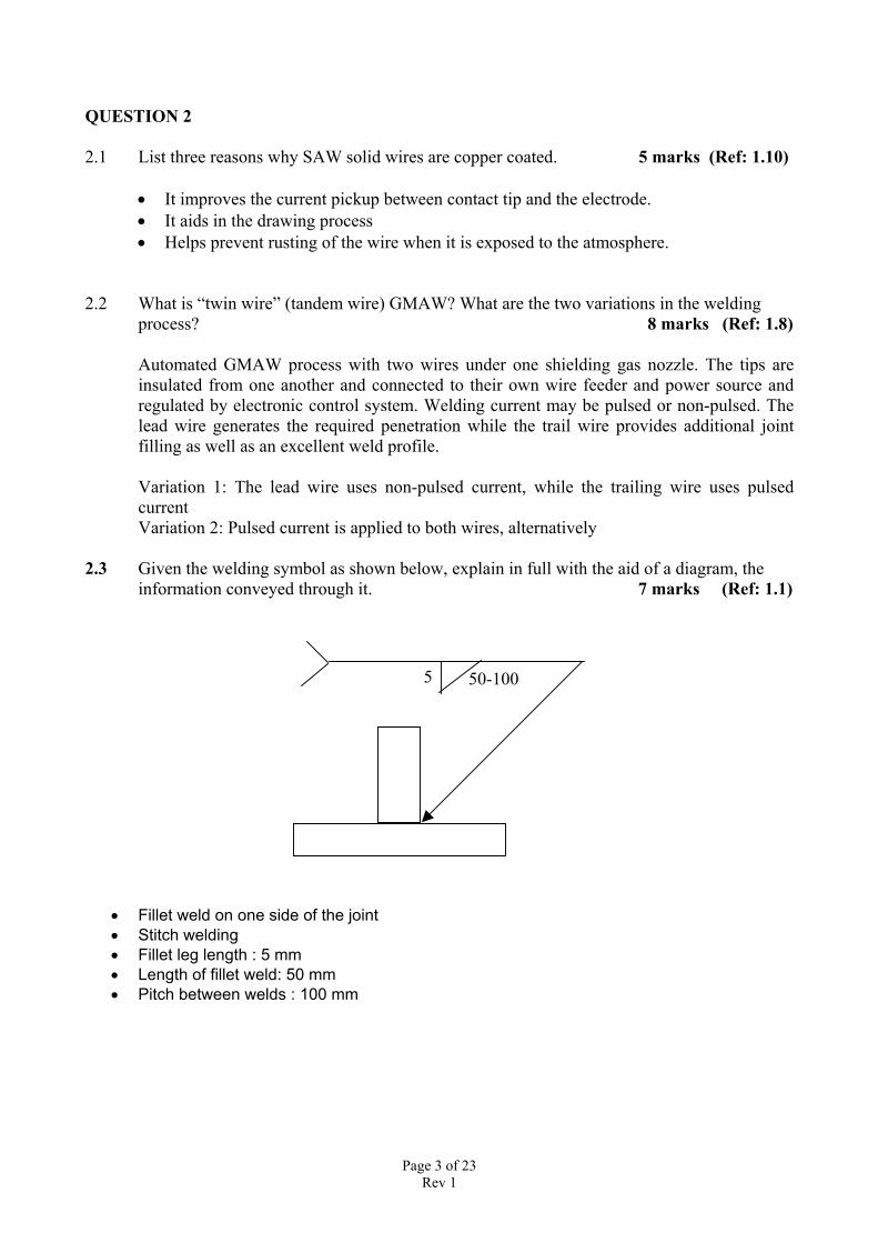
2.3 Given the welding symbol as shown below, explain in full with the aid of a diagram, theinformation conveyed through it. 7 marks (Ref: 1.1)
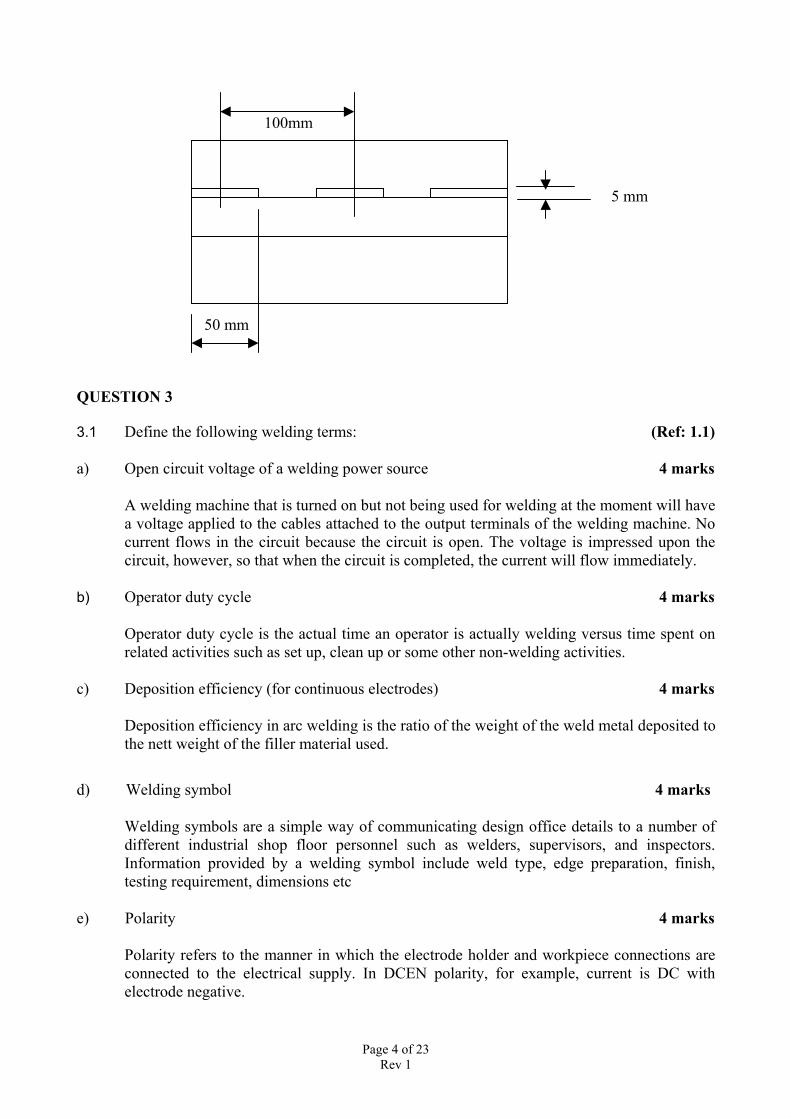
• Fillet weld on one side of the joint• Stitch welding• Fillet leg length : 5 mm• Length of fillet weld: 50 mm• Pitch between welds : 100 mm
5 50-100
Page 4 of 23Rev 1
100mm
5 mm
5050
50 mm
QUESTION 3
3.1 Define the following welding terms: (Ref: 1.1)
a) Open circuit voltage of a welding power source 4 marks
A welding machine that is turned on but not being used for welding at the moment will havea voltage applied to the cables attached to the output terminals of the welding machine. Nocurrent flows in the circuit because the circuit is open. The voltage is impressed upon thecircuit, however, so that when the circuit is completed, the current will flow immediately.
b) Operator duty cycle 4 marks
Operator duty cycle is the actual time an operator is actually welding versus time spent onrelated activities such as set up, clean up or some other non-welding activities.
c) Deposition efficiency (for continuous electrodes) 4 marks
Deposition efficiency in arc welding is the ratio of the weight of the weld metal deposited tothe nett weight of the filler material used.
d) Welding symbol 4 marks
Welding symbols are a simple way of communicating design office details to a number ofdifferent industrial shop floor personnel such as welders, supervisors, and inspectors.Information provided by a welding symbol include weld type, edge preparation, finish,testing requirement, dimensions etc
e) Polarity 4 marks
Polarity refers to the manner in which the electrode holder and workpiece connections areconnected to the electrical supply. In DCEN polarity, for example, current is DC withelectrode negative.
Page 5 of 23Rev 1
QUESTION 4
4.1 Explain the difference between soldering and welding. 5 marks (Ref: 1.1)
Soldering is a group of joining processes that produce coalescence of materials by heatingthem to the soldering temperature and by using a filler metal (solder) having a liquidus notexceeding 450ºC, and below the solidus of the base metals.
In welding, fusion takes place with melting of both the base metal and usually a filler metal.
4.2 Explain the phenomenon of “flashback”. How does a flashback arrestor assist in preventing flashbacks? 7 marks (Ref: 1.2)
Unequal gas pressure can lead to a backflow i.e. mixing of gases in torch, hoses etc that canresult in a flashback. A flashback is the flame burning back into the torch, hoses, regulatoror even the cylinders.
A flashback arrestor is designed to prevent the backflow of gas, quench the flame producedby a flashback and may provide additional protection by shutting off the gas flow if certaintemperatures and/or pressures are exceeded.
4.3 What are Voltage Reducing Devices (VRDs)? List the three types of VRDs commonlyused in the industry. 8 marks (Ref: 1.8)
A device that assists in the reduction of electrical shock to personnel involved in weldingactivities is known as VRD. It is a device that reduces open-circuit voltage to a safe valueuntil welding commences. Upon arc strike, full selected current and voltage becomesavailable. Upon completion of welding, the Open Circuit Voltage is returned to a safe valueuntil the next welding cycle.
The three types of VRDs are:
Type 1: Externally fitted to secondary circuitType 2: Internally fitted to secondary circuitType 3: Fitted to primary circuit
QUESTION 5
5.1 What is magnetic arc blow? State three methods of reducing it. 5 marks (Ref: 1.8, 1.9)
Magnetic arc blow, also called arc wandering, occurs in DC arc welding when the arc doesnot follow the shortest path between the electrode and the workpiece and deflects forwardor backward from the direction of travel or less frequently, to one side.
Some of the methods to reduce it are:
• If DC is being used with MMAW process change to AC• Hold as short an arc as possible to help arc force counteract arc blow
Page 6 of 23Rev 1
• Reduce the welding current• Angle the electrode with the work opposite to the direction of arc blow• Use a backstep welding method• Wrap the work cable around the workpiece so that the current returning to the power
supply passes through it in such a direction that the magnetic field set up neutralises themagnetic field causing the arc blow
5.2 Give five advantages of waterjet cutting over LASER cutting. 5 marks (Ref: 1.12)
• Abrasive waterjets can machine many materials that lasers cannot. (Reflective materialsin particular, such as Aluminum and Copper.)
• Uniformity of material is not very important to an Abrasive jet.• Abrasive jets do not heat the part. Thus there is no thermal distortion or hardening of
the material.• Precision abrasive jet machines can obtain about the same or higher tolerances than
lasers (especially as thickness increases).• Capital equipment costs for water jet are generally much lower than that for a laser.• Abrasive jets can machine thicker materials.• Abrasive jets are safer. No burnt fingers, no noxious fumes and no fires.• Abrasive jets are more environmentally friendly.• Maintenance on the abrasive jet nozzle is simpler than that of a laser, though probably
just as frequent.• Modern Abrasive jets are typically much easier to operate and maintain than lasers• Abrasive jets don't create "scaley" edges, which makes it easier to make a high quality
weld
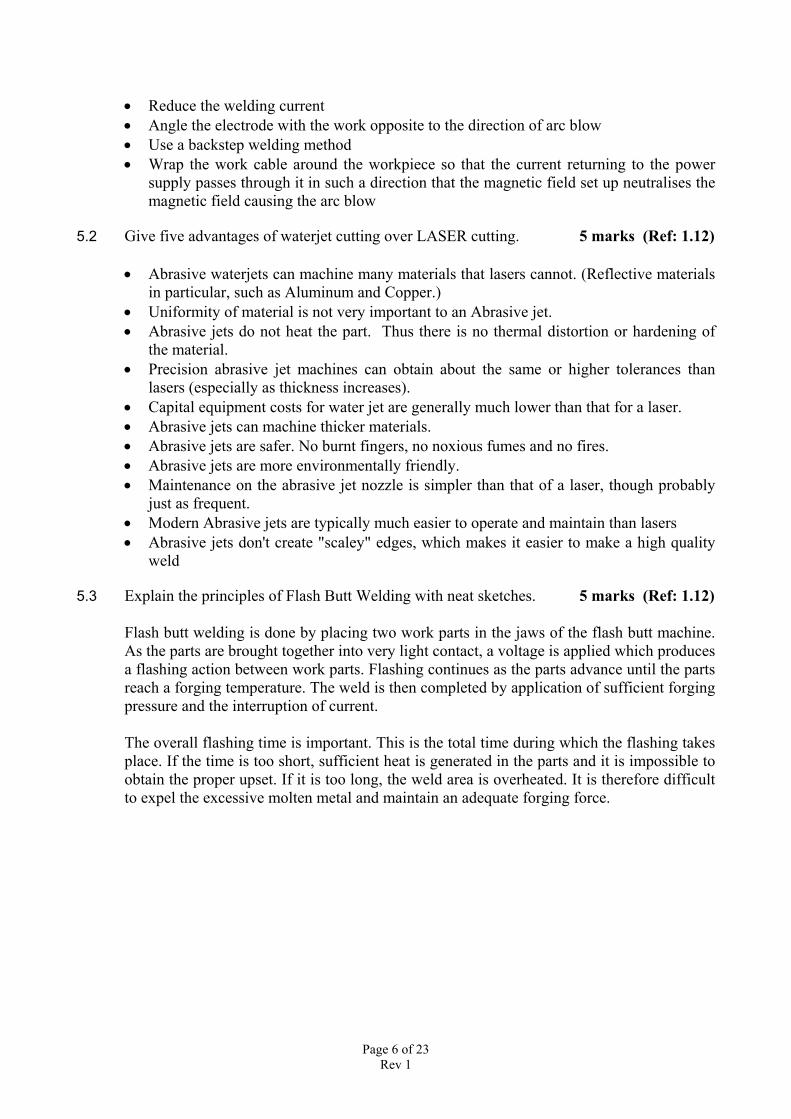
5.3 Explain the principles of Flash Butt Welding with neat sketches. 5 marks (Ref: 1.12)
Flash butt welding is done by placing two work parts in the jaws of the flash butt machine.As the parts are brought together into very light contact, a voltage is applied which producesa flashing action between work parts. Flashing continues as the parts advance until the partsreach a forging temperature. The weld is then completed by application of sufficient forgingpressure and the interruption of current.
The overall flashing time is important. This is the total time during which the flashing takesplace. If the time is too short, sufficient heat is generated in the parts and it is impossible toobtain the proper upset. If it is too long, the weld area is overheated. It is therefore difficultto expel the excessive molten metal and maintain an adequate forging force.
Page 7 of 23Rev 1
Schematic representation of flash butt welding
5.4 List two problems with welding coated steels and give one solution for each problem.
5 marks (Ref: 1.8, 1.9)
For metal arc welding and other high temperature welding methods, precautions must betaken to avoid porosity and cracking of the weld that can be caused by penetration of zincinto the weld pool. High levels of spatter and welding fume and poor bead shape arecommon. The right wire size and type, matched with the most appropriate shielding gas, cansubstantially improve gas metal arc welding (GMAW) performance on galvanized andcoated steels.
For all galvanised products, extremely high welding current is to be avoided, becauseexcessive heating tends to cause expulsion of the zinc coating under the electrodes. Theoptimum setting of the welding parameters must be determined by trial and are dependenton the specific application and sheet characteristics such as thickness or coating weight. Thethicker the zinc coating, the more fumes are generated. In general, resistance welding ispreferred for joining galvanised sheet products because it results in less fuming than othertypes of welding.
Pulsed metal transfer GMAW can help improve galvanized steel weld quality even more.By reducing spatter, it increases process efficiency and minimizes cleanup
Page 8 of 23Rev 1
PAPER SA2MATERIALS AND THEIR BEHAVIOUR DURING
WELDINGQUESTION 1
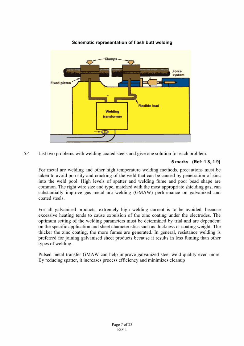
2.1 A steel, with the chemical composition as shown below, and of known heat analysis, is tobe used in structural fabrication. (Ref: 2.7, 2.8, 2.9)
20 All dimensions in mms
C 0.22%Mn 1.20%Ni 0.20% 250Cr 0.40%Mo 0.25%V 0.20%Cu 0.01% 100 100
Continuous fillet welds have to be made simultaneously on a Tee Joint whose thickness is20 mm. MMAW is to be used throughout using 5 mm diameter E 4818 electrodes.(Note: Use WTIA Technote 1:The Weldability of Steels for solving this problem)
i) Calculate the carbon equivalent for this steel 5 marks
Using the IIW formula below and substituting the values:
Ceq = C + Mn/6 + (Cr + Mo + V)/5 + (Ni + Cu)/15 = 0.604 +0.01 = 0.614
ii) For the welding conditions given below, calculate the arc energyArc Voltage = 23 V, Amperage = 230 A, Travel Speed = 200 mm/min 5 marksArc Energy = (Voltage x Current) / Travel Speed = (230x23)/200 = 1.587 kJ
iii) Using the above information and results, determine from the welding data sheets provided
a) The group number of this steel 5 marks
Using the graph in Fig 1 in WTIA Tech Note 1, Group No is 8
b) The preheat necessary for control of HAZ properties of this steel to avoid cold cracking withthe given joint configuration, welding conditions and electrode size 5 marks
Using the graph in Fig 3 in WTIA Tech Note 1, preheat = 1500 C
20
Page 9 of 23Rev 1
QUESTION 22.1 What is re-heat cracking? Explain the reasons why re-heat cracking occurs in low alloy
steels 10 marks (Ref: 2.11)
Reheat cracking may occur in low alloy steels containing alloying additions of chromium,vanadium and molybdenum when the welded component is being subjected to post weldheat treatment, such as stress relief heat treatment, or has been subjected to hightemperature service (typically 350 to 550°C).
Cracking is almost exclusively found in the coarse grained regions of the heat affected zone(HAZ) beneath the weld, or cladding, and in the coarse grained regions within the weldmetal. The cracks can often be seen visually, usually associated with areas of stressconcentration such as the weld toe.
The principal cause is that when heat treating susceptible steels, the grain interior becomesstrengthened by carbide precipitation, forcing the relaxation of residual stresses by creepdeformation at the grain boundaries.
The presence of impurities which segregate to the grain boundaries and promote temperembrittlement, e.g. sulphur, arsenic, tin and phosphorus, will increase the susceptibility toreheat cracking.
The joint design can increase the risk of cracking. For example, joints likely to containstress concentration, such as partial penetration welds, are more liable to initiate cracks.
The welding procedure also has an influence. Large weld beads are undesirable, as theyproduce a coarse grained HAZ which is less likely to be refined by the subsequent pass, andtherefore will be more susceptible to reheat cracking.
2.2 Give four precautions that can assist in re-heat cracking being avoided in low alloy steels.
10 marks (Ref: 2.11)
The risk of reheat cracking can be reduced through the choice of steel, specifying themaximum impurity level and by adopting a more tolerant welding procedure / technique.
Steel choice: If possible, avoid welding steels known to be susceptible to reheat cracking.
Welding procedure and technique:The welding procedure can be used to minimise the risk of reheat cracking by * Producing the maximum refinement of the coarse grain HAZ * Limiting the degree of austenite grain growth * Eliminating stress concentrations
Page 10 of 23Rev 1
QUESTION 3
3.1 The risk of porosity during the welding of aluminium and aluminium alloys can beminimised by rigorous cleaning of material surface and filler wires used. Explain the threecleaning techniques that are available for achieving this. 10 marks (Ref: 2.23)
To minimise the risk, rigorous cleaning of material surface and filler wire should be carriedout. Three cleaning techniques are suitable; mechanical cleaning, solvent degreasing andchemical etch cleaning.
Mechanical cleaning: Wire brushing (stainless steel bristles), scraping or filing can be usedto remove surface oxide and contaminants. Degreasing should be carried out beforemechanical cleaning.
Solvents: Dipping, spraying or wiping with organic solvents can be used to remove grease,oil, dirt and loose particles.
Chemical etching: A solution of 5% sodium hydroxide can be used for batch cleaning butthis should be followed by rinsing in HNO 3 and water to remove reaction products on thesurface.
3.2 How is dilution of filler material defined and expressed? What are the factors that effect thefinal chemical composition and mechanical/physical properties of the welded joint?
10 marks (Ref: 2.25)
Dilution of filler material by the infusion of parent metal during liquidus state in welding isa fundamental process of welding and can be defined as the reduction in alloy content of aweld deposit by virtue of melting and incorporating melted base metal of lower alloycontent
Dilution is commonly expressed as the percentage of base metal that has entered into theweld metal.
The factors that affect the final composition are:
• The type of process being used• The parameters being used by the process• The nature of the base and filler materials
QUESTION 4
4.1 What is a phase diagram (also called equilibrium diagram or constitution diagram)? Give two uses of the iron-carbon equilibrium diagram. 8 marks (Ref: 2.4)
It is a two-dimensional graph which indicates the phases present at a given temperature andcomposition.
Page 11 of 23Rev 1
• To get some idea of the conditions of temperature and pressure that are most likely toproduce a gas, a liquid, or a solid.
• To find the combinations of temperature and pressure at which two states are in
equilibrium.
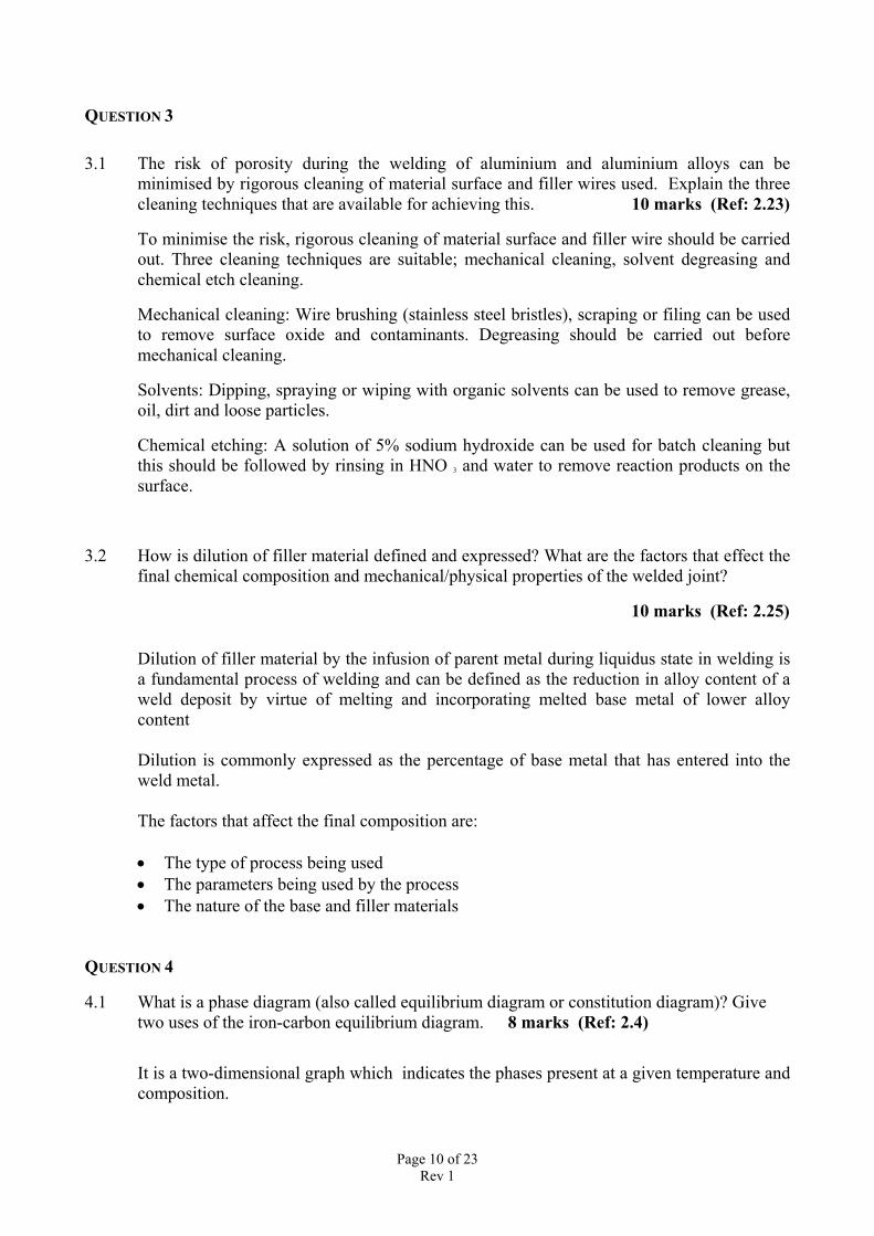
4.2 With the aid of a diagram , describe the phenomenon of creep. State three elements thatcontribute to the rate of creep damage. 12 marks (Ref: 2.14)
Creep is the term given to the material deformation that occurs as a result of long termexposure to levels of stress that are below the yield or ultimate strength. Rather than failingsuddenly with a fracture, the material permanently strains over a longer period of time untilit finally fails. Creep does not happen upon sudden loading but the accumulation of creepstrain in longer times causes failure of the material. This makes creep deformation a "time-dependent" deformation of the material.
The rate of this damage is a function of the material properties and the exposure time,exposure temperature and the applied load (stress). Depending on the magnitude of theapplied stress and its duration, the deformation may become so large that a component canno longer perform its function
QUESTION 5
5.1 What is the effect of corrosion on the fatigue strength of welded structures? 6 marks (Ref: 2.15)
The presence of a corrosive environment may accelerate fatigue crack propagation instructural steels. If pitting conditions exist, development of corrosion pits will introduceadditional points of stress concentration at which cracking may develop. Both thesemechanisms are likely to reduce fatigue strength below that in an inert environment.
Page 12 of 23Rev 1
5.2 Give two reasons why preheat is used when welding a high carbon equivalent steel? Listtwo methods of applying preheat. 6 marks (Ref: 2.8, 2.9)
Preheating is the process applied to raise the temperature of the parent steel before welding.It is used for the following main reasons:
• To slow the cooling rate of the weld and the base material, resulting in softer weld metaland heat affected zone microstructures with a greater resistance to fabrication hydrogencracking.
• The slower cooling rate encourages hydrogen diffusion from the weld area by extending thetime period over which it is at elevated temperature (particularly the time at temperaturesabove approximately 100°C) at which temperatures hydrogen diffusion rates aresignificantly higher than at ambient temperature. The reduction in hydrogen reduces the riskof cracking.
Preheat can be applied through various means. The choice of method of applying preheatwill depend on the material thickness, weldment size and the heating equipment available atthe time of welding. The methods can include furnace heating for small productionassemblies or, for large structural components, arrays of torches, electrical strip heaters,induction heaters or radiation heaters.
5.3 List two specific imperfections that can result in the welding of each of the following:
a) Austenitic stainless steel 4 marks (Ref: 2.16)
Common imperfections found on welding are:
Although austenitic stainless steel is readily welded, weld metal and HAZ cracking canoccur. Weld metal solidification cracking is more likely in fully austenitic structures whichare more crack sensitive than those containing a small amount of ferrite.
b) Copper and copper alloys 4 marks (Ref: 2.21)
In fusion welding tough pitch copper, high oxygen content leads to embrittlement in theheat affected zone (HAZ) and weld metal porosity. Phosphorus deoxidised copper is moreweldable but residual oxygen can result in porosity in autogenous welds especially in thepresence of hydrogen. Porosity is best avoided by using appropriate filler wire containingdeoxidants (Al, Mn, Si, P and Ti).
Page 13 of 23Rev 1
PAPER SA3CONSTRUCTION AND DESIGN
QUESTION 1 5 marks ( Ref: 3.1, 3.2, 3.3, 3.4)
1.1 What is meant by “joint efficiency”
Joint efficiency is the ratio between the tensile strength of the joint and the tensile strengthof the parent material expressed as a percentage
1.2 Define the “design throat thickness” and “load carrying area” for a fillet weld8 marks
Design throat thickness is the shortest distance from the root of the fillet weld to the linedrawn between the toes of the weld.
The load carrying area is the design throat thickness multiplied by the length of the weld.
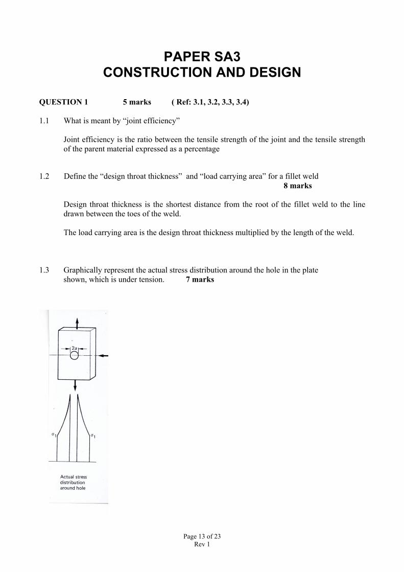
1.3 Graphically represent the actual stress distribution around the hole in the plateshown, which is under tension. 7 marks
Page 14 of 23Rev 1
QUESTION 2
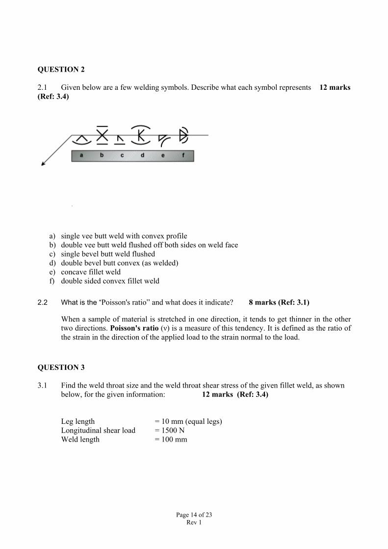
2.1 Given below are a few welding symbols. Describe what each symbol represents 12 marks(Ref: 3.4)
a) single vee butt weld with convex profileb) double vee butt weld flushed off both sides on weld facec) single bevel butt weld flushedd) double bevel butt convex (as welded)e) concave fillet weldf) double sided convex fillet weld
2.2 What is the “Poisson's ratio” and what does it indicate? 8 marks (Ref: 3.1)
When a sample of material is stretched in one direction, it tends to get thinner in the othertwo directions. Poisson's ratio (ν) is a measure of this tendency. It is defined as the ratio ofthe strain in the direction of the applied load to the strain normal to the load.
QUESTION 3
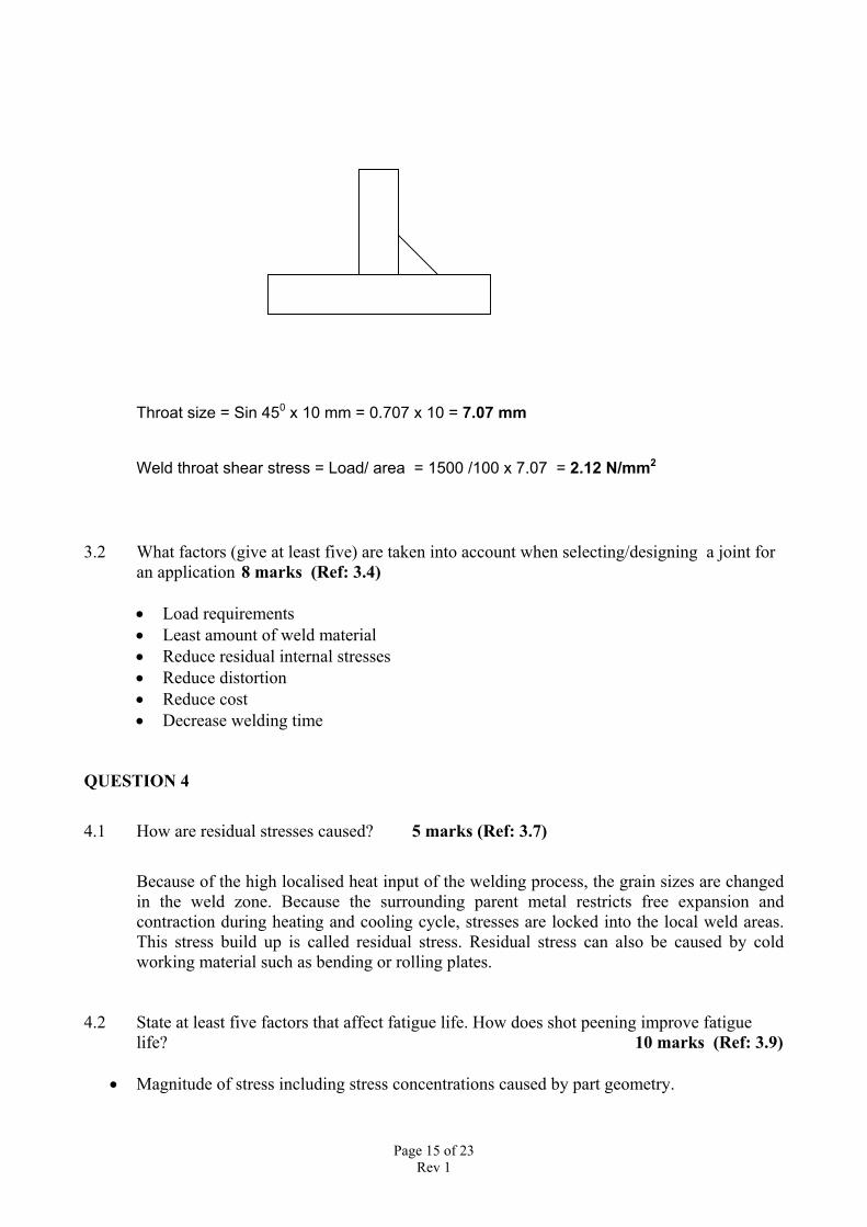
3.1 Find the weld throat size and the weld throat shear stress of the given fillet weld, as shownbelow, for the given information: 12 marks (Ref: 3.4)
Leg length = 10 mm (equal legs)Longitudinal shear load = 1500 NWeld length = 100 mm
Page 15 of 23Rev 1
Throat size = Sin 450 x 10 mm = 0.707 x 10 = 7.07 mm
Weld throat shear stress = Load/ area = 1500 /100 x 7.07 = 2.12 N/mm2
3.2 What factors (give at least five) are taken into account when selecting/designing a joint foran application 8 marks (Ref: 3.4)
• Load requirements• Least amount of weld material• Reduce residual internal stresses• Reduce distortion• Reduce cost• Decrease welding time
QUESTION 4
4.1 How are residual stresses caused? 5 marks (Ref: 3.7)
Because of the high localised heat input of the welding process, the grain sizes are changedin the weld zone. Because the surrounding parent metal restricts free expansion andcontraction during heating and cooling cycle, stresses are locked into the local weld areas.This stress build up is called residual stress. Residual stress can also be caused by coldworking material such as bending or rolling plates.
4.2 State at least five factors that affect fatigue life. How does shot peening improve fatiguelife? 10 marks (Ref: 3.9)
• Magnitude of stress including stress concentrations caused by part geometry.
Page 16 of 23Rev 1
• Quality of the surface; surface roughness, scratches, etc. cause stress concentrations orprovide crack nucleation sites which can lower fatigue life depending on how the stress isapplied.
• Surface defect geometry and location. The size, shape, and location of surface defects suchas scratches, gouges, and dents can have a significant impact on fatigue life.
• Significantly uneven cooling, leading to a heterogeneous distribution of material propertiessuch as hardness and ductility and, in the case of alloys, structural composition.
• Size, frequency, and location of internal defects. Casting defects such as gas porosity andshrinkage voids, for example, can significantly impact fatigue life.
• In metals where strain-rate sensitivity is observed (ferrous metals, copper, titanium, etc.)strain rate also affects fatigue life in low-cycle fatigue situations.
• For non-isotropic materials, the direction of the applied stress can affect fatigue life.• Grain size; for most metals, fine-grained parts exhibit a longer fatigue life than coarse-
grained parts. Environmental conditions and exposure time can cause erosion, corrosion, orgas-phase embrittlement, which all affect fatigue life.
Shot peening puts the surface in a state of compressive stress which inhibits crack formationthus improving fatigue life
4.3 What significant properties does “9% Ni steel” have and what applications is it used for ? 5 marks ( Ref: 3.6, 3.10)
The only alloy steel recommended for cryogenic service is 9% nickel steel. It is satisfactoryfor service down to -195°C and is used for transport and storage of cryogenics because of itslow cost and ease of fabrication. Other alloy steels are suitable for service in the low-temperature range. The steels A201 and T-1 can suffice to -45°C, nickel steels with 2.25%Ni can suffice to -59°C, and nickel steels with 3.5% Ni to-101°C.
QUESTION 5
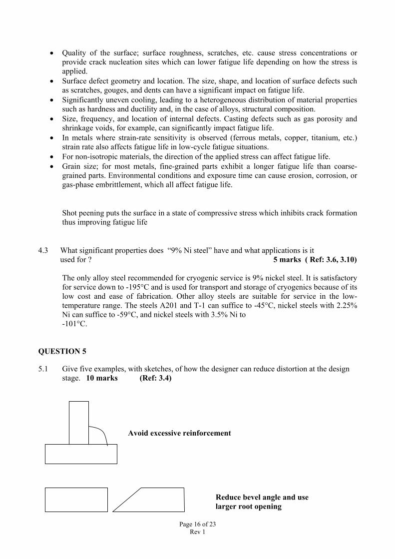
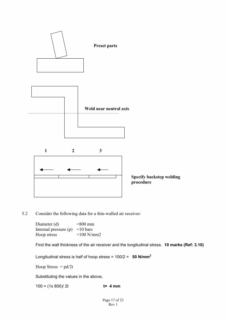
5.1 Give five examples, with sketches, of how the designer can reduce distortion at the designstage. 10 marks (Ref: 3.4)
Avoid excessive reinforcement
Reduce bevel angle and use larger root opening
Page 17 of 23Rev 1
Preset parts
Weld near neutral axis
1 2 3
1
Specify backstep weldingprocedure
5.2 Consider the following data for a thin-walled air receiver:
Diameter (d) =800 mmInternal pressure (p) =10 barsHoop stress =100 N/mm2
Find the wall thickness of the air receiver and the longitudinal stress. 10 marks (Ref: 3.10)
Longitudinal stress is half of hoop stress = 100/2 = 50 N/mm2
Hoop Stress = pd/2t
Substituting the values in the above,
100 = (1x 800)/ 2t t= 4 mm
Page 18 of 23Rev 1
PAPER SA4FABRICATION AND APPLICATIONS
ENGINEERINGQUESTION 1 (Ref: 4.1, 4.2)
1.1 List the three stages in the development of welding procedures. 5 marks• The proposed welding procedure• The procedure qualification record-PQR• The welding procedure specification- WPS
1.2 List five common essential variables for the MMAW process with reference to AS/NZS 1554 Part 1. 5 marks
• A change in specified mean arc voltage• A change in specified mean welding current• A change in position in which the welding is done or change in welding direction• A change from single pass to multipass• A change in minimum specified preheat or inter-run temperature
1.3 List the five methods of qualifying welding procedures available in AS/NZS 1554 Part1. 10 marks
• A pre-qualified procedure• Production of documentary evidence of relevant prior experience by the fabricator• Production of a suitable length of test piece of the same joint type, material type,
material thickness and edge preparation, material type and direction of rolling• Preparation of a special test piece• Destructive testing of a prototype joint• A welding procedure qualified by another fabricator
QUESTION 2 (Ref: 4.1, 4.2)
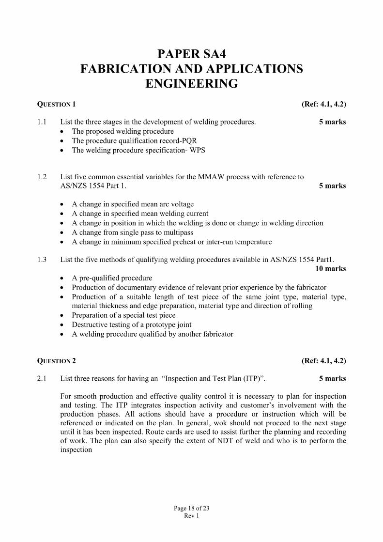
2.1 List three reasons for having an “Inspection and Test Plan (ITP)”. 5 marks
For smooth production and effective quality control it is necessary to plan for inspectionand testing. The ITP integrates inspection activity and customer’s involvement with theproduction phases. All actions should have a procedure or instruction which will bereferenced or indicated on the plan. In general, wok should not proceed to the next stageuntil it has been inspected. Route cards are used to assist further the planning and recordingof work. The plan can also specify the extent of NDT of weld and who is to perform theinspection
Page 19 of 23Rev 1
2.2 List ten components or elements of a typical ITP. 5 marks
Material (at source of supply) Material testing
Material (receipt) Material cutting
Component – mark out Component – flame cutting
Fitup components Weld procedures
Welder qualification Welding
Pressure testing Prior to painting
Grit blasting Painting
Assembly Packing & Dispatch
Documentation
2.3 What is the intended action for the manufacturer's inspector when the following test points
are specified in the ITP?
a) H 5 marks
Fabrication is not to proceed until manufacturer’s inspector has verified the performance
and results of the inspection and test.
b) W 5 marks
Fabrication is not to proceed until the manufacturer’s inspector has verified the performance
and results of the inspection and test. The inspector may delegate this authority to a suitable
trained person whose training has been approved and recorded by the manufacturer.
QUESTION 3 (REF: 4.1, 4.2)
3.1 Give three reasons for lamellar tearing to occur. 6 marks
1. Transverse strain - the shrinkage strains on welding must act in the short direction of theplate i.e. through the plate thickness
2. Weld orientation - the fusion boundary will be roughly parallel to the plane of the inclusions
3. Material susceptibility - the plate must have poor ductility in the through-thickness direction
Page 20 of 23Rev 1
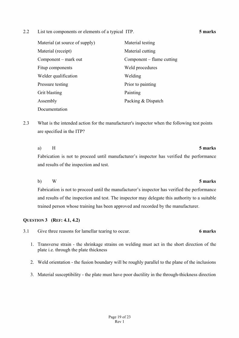
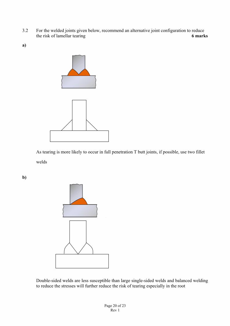
3.2 For the welded joints given below, recommend an alternative joint configuration to reducethe risk of lamellar tearing 6 marks
a)
As tearing is more likely to occur in full penetration T butt joints, if possible, use two fillet
welds
b)
Double-sided welds are less susceptible than large single-sided welds and balanced weldingto reduce the stresses will further reduce the risk of tearing especially in the root
Page 21 of 23Rev 1
3.3 Give two possible causes for each of the welding imperfections and one method ofpreventing each cause.
i) Excessive weld metal 4 marks
Excessive weld metal which is usually a result of poor welder technique for manualprocesses but may be due to poor parameter selection when the process is mechanised. Thatis, too much filler metal for the travel speed used.
If the imperfection is a result of welder technique then welder retraining is required. Formechanised techniques an increase in travel speed or voltage will help to reduce cap height.
ii) Undercut 4 marks
A wide spreading arc (high arc voltage) with insufficient fill (low current or high travel
speed) is the usual cause. However, welder technique, especially when weaving, and the
way the welding torch is angled can both cause and be used to overcome undercutting ( ie
angled to push the weld metal to fill the melted groove). High welding current will also
cause undercut - this is generally associated with the need for a high travel speed to avoid
overfilling of the joint.
This imperfection may be avoided by reducing travel speed and/or the welding current and
by maintaining the correct arc length.
QUESTION 4 (REF: 4.8)
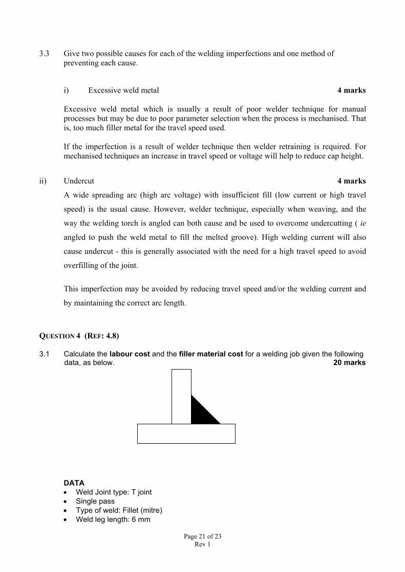
3.1 Calculate the labour cost and the filler material cost for a welding job given the following data, as below. 20 marks
DATA• Weld Joint type: T joint• Single pass• Type of weld: Fillet (mitre)• Weld leg length: 6 mm
Page 22 of 23Rev 1
• Total weld length: 1000 mm• Material: Carbon steel• Welding Process: GMAW• Wire diameter = 0.9 mm• Deposition Efficiency = 95%• Deposition Rate = 3.6 kg/hr• Density of steel = 7.85 x 10³ kg/m3
• Cost of filler material = $5/kg• Hourly labour rate (including overhead) = $25• Operator Factor = 60%
Area of cross section of electrode = ½ x base x height = ½ x 0.6 x 0.6 = 0.18 cm2
Volume of weld metal = area of cross section x length = 0.18 x 100 = 18 cm3
Weight of weld metal = Density x volume = 7.85 x 18 / 1000 = 0.1413 kg
Actual weld metal used = weight/ deposition efficiency = 0.1413/0.95 = 0.1487 kg
Filler metal cost = Actual weld metal used x cost of filler material = 0.1487 x 5 = $ 0.7435
Arc on time = Weld metal deposited/ Deposition rate = 0.1487/3.6 x 60 = 2.47 mins
Labour hours = Arc on time / Operator factor = 2.47/0.6 = 4.13 mins
Labour cost = Labour hours x Labour rate = 4.13/60 x 25 = $1.72
QUESTION 5 (REF: 4.7, 4.9)
5.1 State two limitations of the ultrasonic inspection method 4 marks
• Permanent record is difficult to obtain• Requires high level of skill in interpreting indications
5.2 How is the penetrameter used to determine the sensitivity of the radiograph? 4 marks
In order to determine the sensitivity of a radiograph, a penetrameter or image qualityindicator is used. IQI are used as a means of assessing the image quality of the radiograph.
For a wire laid across a weld, the diameter of the smallest wire that is visible to the eyeunder the correct lighting conditions is established. To then calculate the IQI sensitivity ofthe radiograph, tables can be used as given in the National Standard or the diameter of thewire is divided by the weld thickness and then multiplied by 100 to give the sensitivitypercentage
5.3 List the general steps involved in the repairs of cast iron components for large areas12 marks
• For larger areas, MMAW or powder technique can be used for buttering the edges of thejoint followed by MMAW or GMAW/FCAW welding to fill the groove.
Page 23 of 23Rev 1
• Remove defective area preferably by grinding or tungsten carbide burr. If air arc orMMA gouging is used, the component must be preheated locally to typically 300degrees C.
• After gouging, the prepared area should be lightly ground to remove any hardenedmaterial.
• Preheat the casting to the required temperature
• Butter the surface of the groove with MMAW using a small diameter (2.4mm or 3mm)electrode; use a nickel or Monel rod to produce a soft, ductile 'buttered' layer;alternatively use oxy-acetylene with a powder consumable.
• Remove slag and peen each weld bead whilst still hot.
• Fill the groove using nickel (3 or 4mm diameter) or nickel-iron electrodes for greaterstrength.
• Finally, to avoid cracking through residual stresses, the weld area should be covered toensure the casting will cool slowly to room temperature


