Isolated RS232 and RS485 ExpansionBoard User Guide
The Silicon Labs Isolated RS232 and RS485 Evaluation Board isa hardware plugin card for EFM8 and EFM32 Starter Kits (STKs).The Isolated RS232 and RS485 EXP is intended to help demon-strate and evaluate applications for Silicon Labs isolation andMCU products. Silicon Labs isolation products create a CMOSbarrier to protect components while still allowing for communica-tion and power transfer. Silicon Labs MCU products offer broadsolutions for low power, industrial, consumer electronics andmore. Software demos are available for connecting the MCU Iso-lated RS232 and RS485 EXP and can be downloaded and runthrough Simplicity Studio™. The demos send signals across theisolation barrier and the message is seen by the user on a termi-nal or on the screen of the MCU STK. They also showcase SiliconLabs ISOVolt technology as the MCU powers components acrossthe isolation barrier.Note: For full use and evaluation of the Isolated RS232 and RS485 EXP a MCU STK isneeded. For full demonstration, two MCU STKs and two Isolated RS232 and RS485EXPs are needed to communicate between one another. Software examples are provi-ded for two MCU STKs, the EFM32 Wonder Gecko Starter Kit EFM32WG-STK3800 andthe EFM8 Universal Bee 1 Starter Kit SLSTK2000A.
KEY FEATURES OR KEY POINTS
• 20-pin headers for connection to EFM8and EFM32 starter kits
• Software demos available in SimplicityStudio
• Power and communication over isolationbarrier
• Jumpers for easy manual control of inputsignals
silabs.com | Building a more connected world. Rev. 0.1
1. Kit Contents
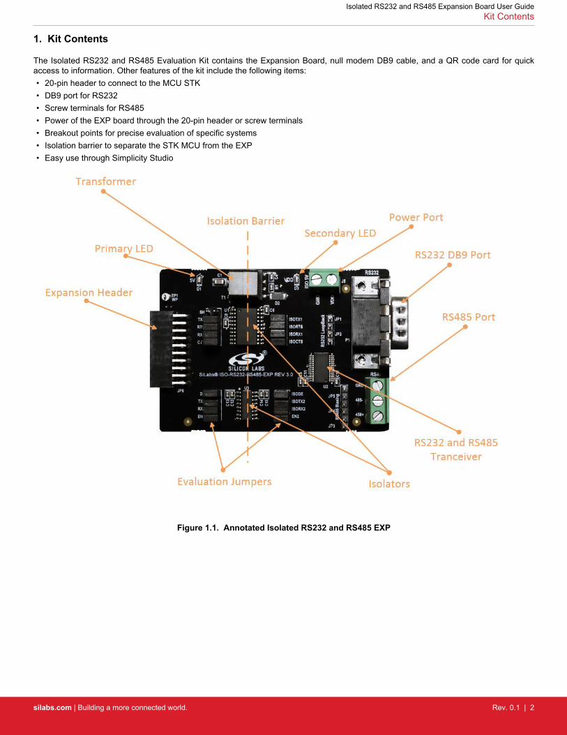
The Isolated RS232 and RS485 Evaluation Kit contains the Expansion Board, null modem DB9 cable, and a QR code card for quickaccess to information. Other features of the kit include the following items:• 20-pin header to connect to the MCU STK• DB9 port for RS232• Screw terminals for RS485• Power of the EXP board through the 20-pin header or screw terminals• Breakout points for precise evaluation of specific systems• Isolation barrier to separate the STK MCU from the EXP• Easy use through Simplicity Studio
Figure 1.1. Annotated Isolated RS232 and RS485 EXP
Isolated RS232 and RS485 Expansion Board User GuideKit Contents
silabs.com | Building a more connected world. Rev. 0.1 | 2
2. Details and Applications
This evaluation kit and associated demos allow the MCU STK, Isolated RS232 and RS485 EXP, and sensors to communicate throughthe RS ports on the EXP board while being isolated. The MCU communicates through UART to the isolation devices. These signals arecarried through the barrier into an RS transceiver which converts it to either RS485 or RS232. Then, the RS ports can be read by a hostor another MCU/EXP combination. The RS communication protocols, especially RS485, are widely used in industrial and commercialapplications where long wires, multiple nodes, high power, or noise are common. Isolation is widely needed in the following markets:• Industrial automation systems• Medical electronics• Hybrid electric vehicles• PLCs, distributed control systems• Isolated switch mode supplies• Isolated ADC and DACs• Motor control• Power inverters• Communication systems
All of these market segments use various communication protocols, such as RS485, CAN, I2C, SPI, UART and the combination of Sili-con Labs isolators and MCU products can serve any of these segments.
2.1 Hardware
The Isolated RS232 and RS485 EXP key components are:• Si88242ED-IS - Digital Isolator with Integrated DC-DC Converter containing 4 unidirectional channels, Automotive, 20-pin SOIC• Si8631BB-B-IS1- Digital CMOS Isolator with 3 channels, up to 150Mbps, Automotive, 16-Pin SOIC• ISL3332IAZ – RS232 and RS485 transceiver• UTB02268s – Power inverter
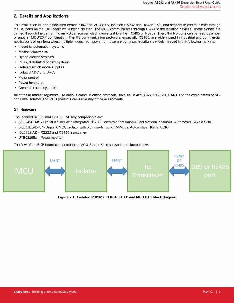
The flow of the EXP board connected to an MCU Starter Kit is shown in the figure below.
MCUUART
RS Transciever
RS242 OR
RS485
Isolator
UARTDB9 or RS485
port
Figure 2.1. Isolated RS232 and RS485 EXP and MCU STK block diagram
Isolated RS232 and RS485 Expansion Board User GuideDetails and Applications
silabs.com | Building a more connected world. Rev. 0.1 | 3

2.1.1 Jumpers and Headers
Isolated RS232 and RS485 EXP contains many jumpers and headers for easy debugging and added functionality.
J1 and J2 contain the 4 wire RS232 signals with J1 coming from the MCU and J2 coming from the transceiver.
J1 also contains the shutdown jumper for the isolator. With this populated, the DC-DC converter is disabled and no power will be sentover the barrier. The other side of the isolation barrier must then be powered separately via the J5 port. With J1 unpopulated, power willflow over the isolation barrier and only one power source is needed.
J3 and J4 contain the RS485 signals with J3 coming from the MCU and J4 coming from the transceiver.
JP1 and JP2 allow loopback of the RS232 signals in the occurrence that no RS232 host or device is available.
JP4 and JP5 allow for RS485 biasing.
The schematics for the board are found in Figure 3.
Figure 2.2. Isolated USB EXP Schematic
Isolated RS232 and RS485 Expansion Board User GuideDetails and Applications
silabs.com | Building a more connected world. Rev. 0.1 | 4
2.1.2 Header Connections
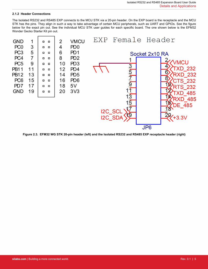
The Isolated RS232 and RS485 EXP connects to the MCU STK via a 20-pin header. On the EXP board is the receptacle and the MCUSTK has the pins. They align in such a way to take advantage of certain MCU peripherals, such as UART and GPIOs. See the figurebelow for the exact pin out. See the individual MCU STK user guides for each specific board. The one shown below is the EFM32Wonder Gecko Starter Kit pin out.
Figure 2.3. EFM32 WG STK 20-pin header (left) and the Isolated RS232 and RS485 EXP receptacle header (right)
Isolated RS232 and RS485 Expansion Board User GuideDetails and Applications
silabs.com | Building a more connected world. Rev. 0.1 | 5
3. Getting Started
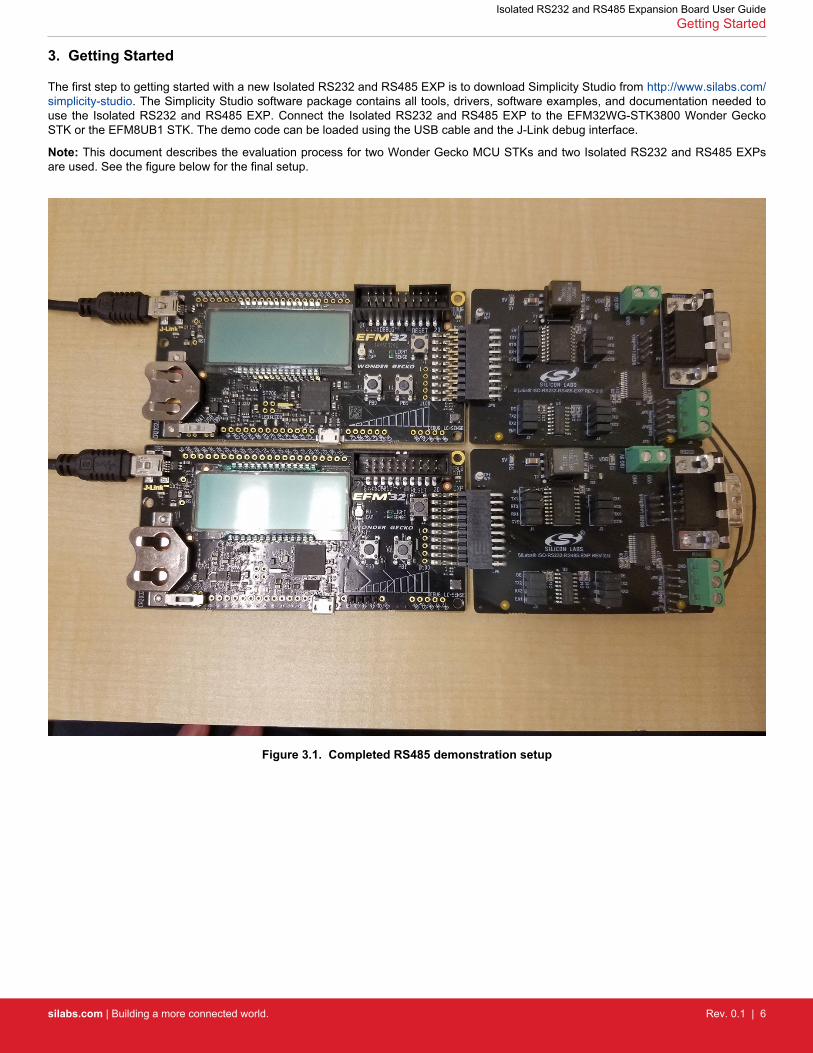
The first step to getting started with a new Isolated RS232 and RS485 EXP is to download Simplicity Studio from http://www.silabs.com/simplicity-studio. The Simplicity Studio software package contains all tools, drivers, software examples, and documentation needed touse the Isolated RS232 and RS485 EXP. Connect the Isolated RS232 and RS485 EXP to the EFM32WG-STK3800 Wonder GeckoSTK or the EFM8UB1 STK. The demo code can be loaded using the USB cable and the J-Link debug interface.
Note: This document describes the evaluation process for two Wonder Gecko MCU STKs and two Isolated RS232 and RS485 EXPsare used. See the figure below for the final setup.
Figure 3.1. Completed RS485 demonstration setup
Isolated RS232 and RS485 Expansion Board User GuideGetting Started
silabs.com | Building a more connected world. Rev. 0.1 | 6
3.1 Loading RS485 Software Demo
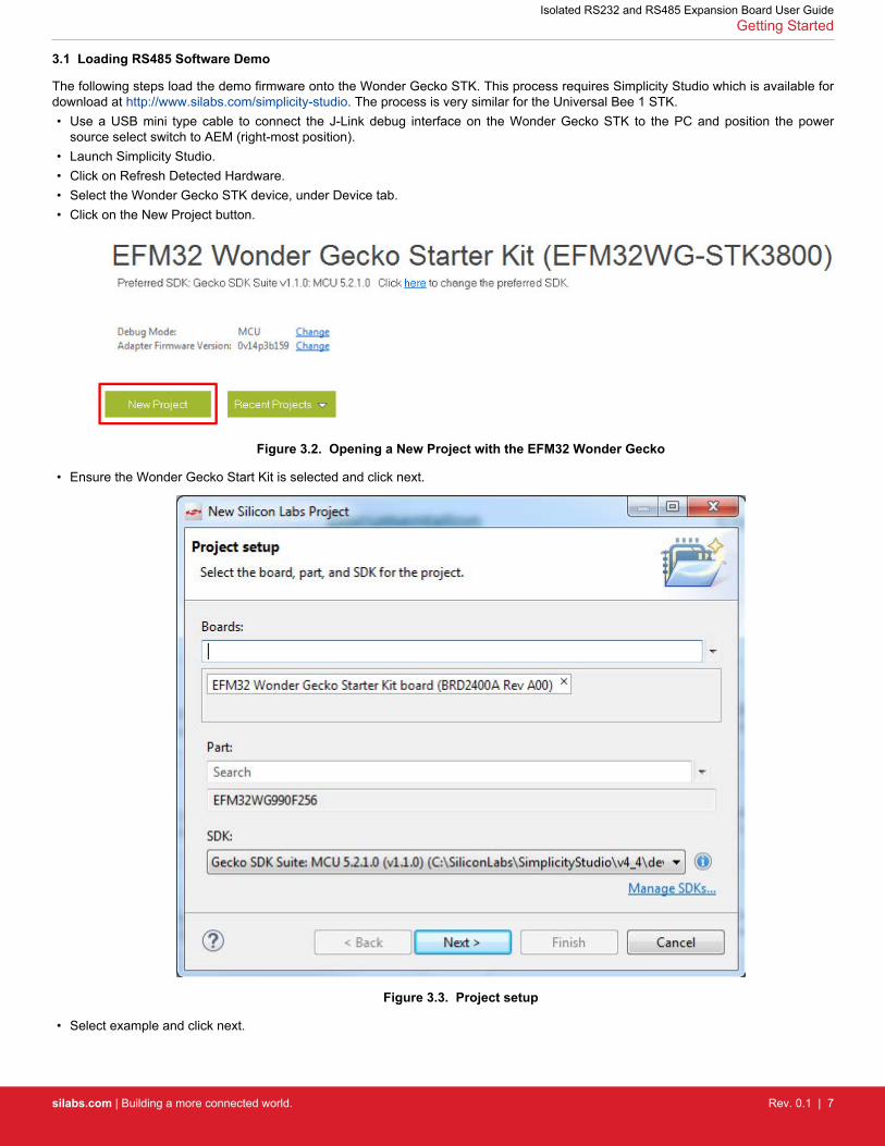
The following steps load the demo firmware onto the Wonder Gecko STK. This process requires Simplicity Studio which is available fordownload at http://www.silabs.com/simplicity-studio. The process is very similar for the Universal Bee 1 STK.• Use a USB mini type cable to connect the J-Link debug interface on the Wonder Gecko STK to the PC and position the power
source select switch to AEM (right-most position).• Launch Simplicity Studio.• Click on Refresh Detected Hardware.• Select the Wonder Gecko STK device, under Device tab.• Click on the New Project button.
Figure 3.2. Opening a New Project with the EFM32 Wonder Gecko
• Ensure the Wonder Gecko Start Kit is selected and click next.
Figure 3.3. Project setup
• Select example and click next.
Isolated RS232 and RS485 Expansion Board User GuideGetting Started
silabs.com | Building a more connected world. Rev. 0.1 | 7
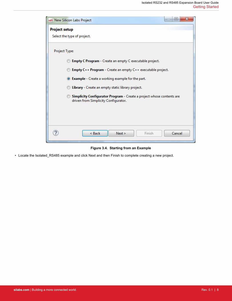
Figure 3.4. Starting from an Example
• Locate the Isolated_RS485 example and click Next and then Finish to complete creating a new project.
Isolated RS232 and RS485 Expansion Board User GuideGetting Started
silabs.com | Building a more connected world. Rev. 0.1 | 8
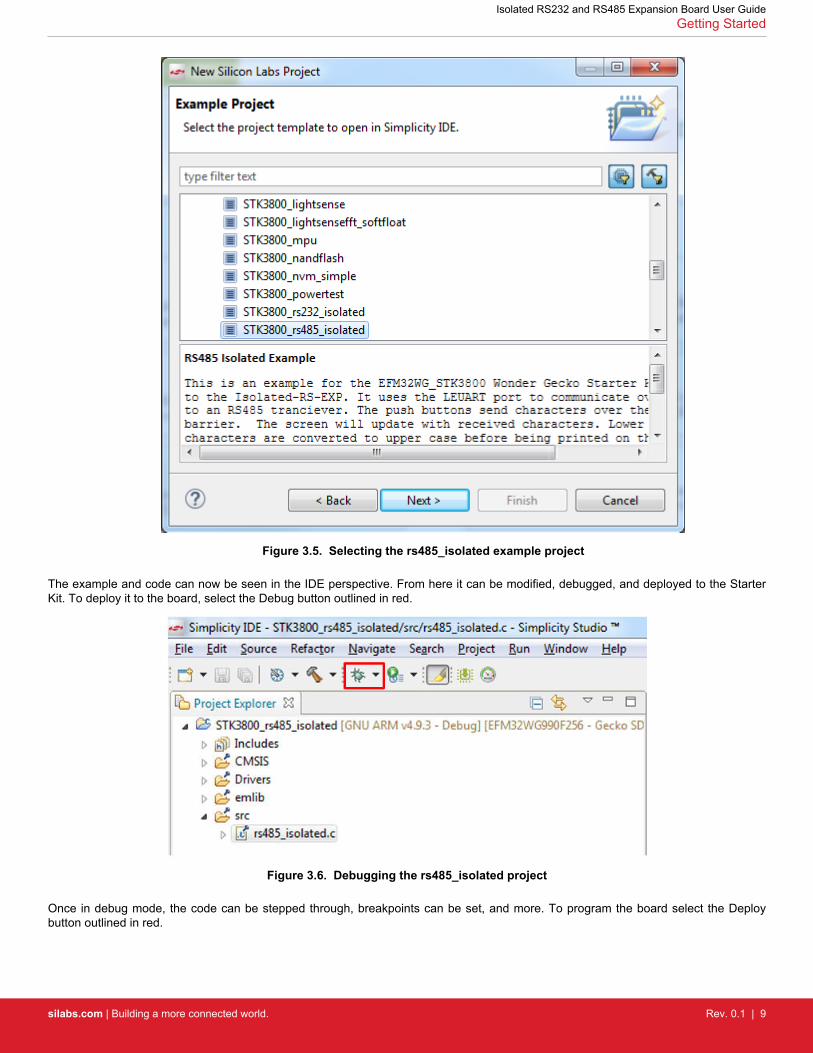
Figure 3.5. Selecting the rs485_isolated example project
The example and code can now be seen in the IDE perspective. From here it can be modified, debugged, and deployed to the StarterKit. To deploy it to the board, select the Debug button outlined in red.
Figure 3.6. Debugging the rs485_isolated project
Once in debug mode, the code can be stepped through, breakpoints can be set, and more. To program the board select the Deploybutton outlined in red.
Isolated RS232 and RS485 Expansion Board User GuideGetting Started
silabs.com | Building a more connected world. Rev. 0.1 | 9
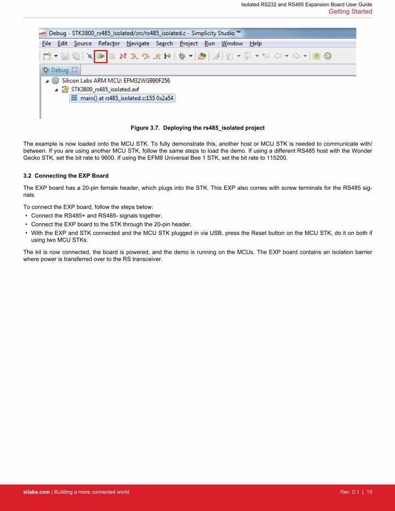
Figure 3.7. Deploying the rs485_isolated project
The example is now loaded onto the MCU STK. To fully demonstrate this, another host or MCU STK is needed to communicate with/between. If you are using another MCU STK, follow the same steps to load the demo. If using a different RS485 host with the WonderGecko STK, set the bit rate to 9600. If using the EFM8 Universal Bee 1 STK, set the bit rate to 115200.
3.2 Connecting the EXP Board
The EXP board has a 20-pin female header, which plugs into the STK. This EXP also comes with screw terminals for the RS485 sig-nals.
To connect the EXP board, follow the steps below:• Connect the RS485+ and RS485- signals together.• Connect the EXP board to the STK through the 20-pin header.• With the EXP and STK connected and the MCU STK plugged in via USB, press the Reset button on the MCU STK, do it on both if
using two MCU STKs.
The kit is now connected, the board is powered, and the demo is running on the MCUs. The EXP board contains an isolation barrierwhere power is transferred over to the RS transceiver.
Isolated RS232 and RS485 Expansion Board User GuideGetting Started
silabs.com | Building a more connected world. Rev. 0.1 | 10
3.3 Using and Understanding the RS485 Example
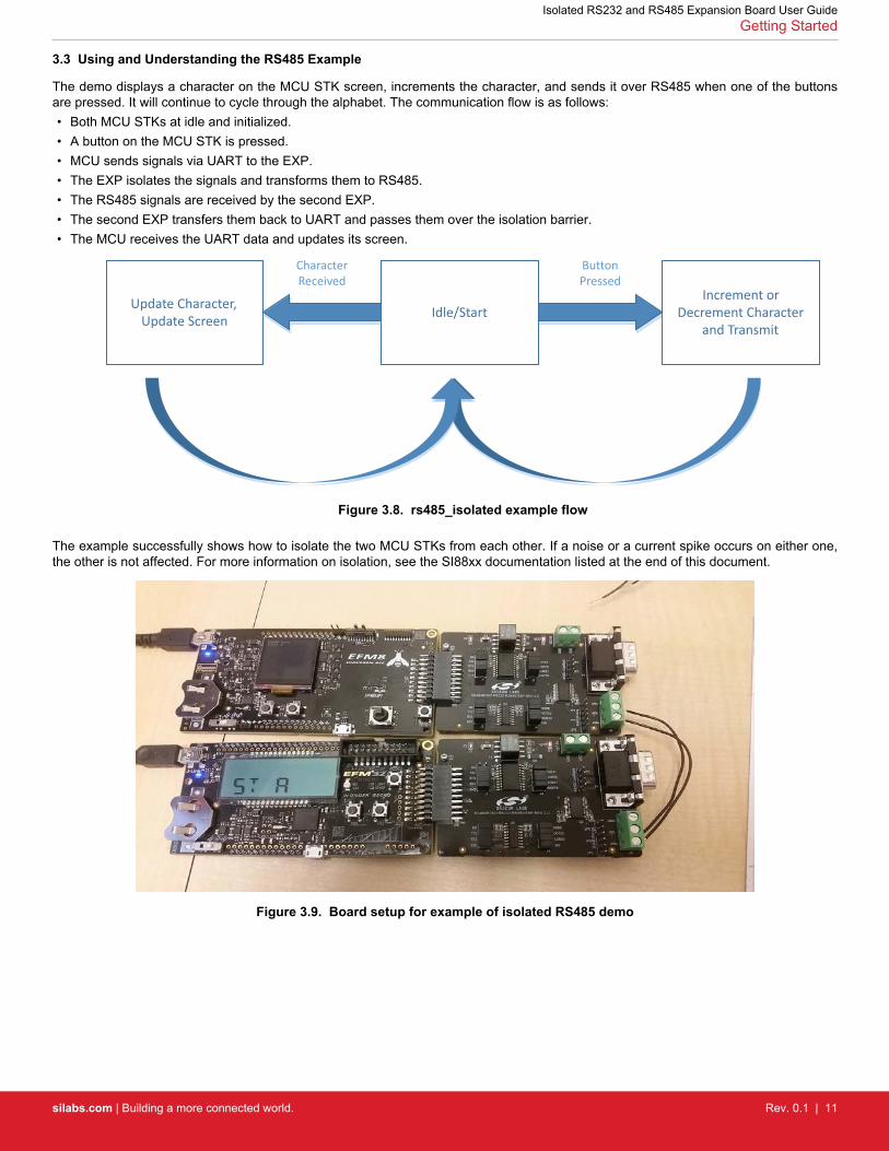
The demo displays a character on the MCU STK screen, increments the character, and sends it over RS485 when one of the buttonsare pressed. It will continue to cycle through the alphabet. The communication flow is as follows:• Both MCU STKs at idle and initialized.• A button on the MCU STK is pressed.• MCU sends signals via UART to the EXP.• The EXP isolates the signals and transforms them to RS485.• The RS485 signals are received by the second EXP.• The second EXP transfers them back to UART and passes them over the isolation barrier.• The MCU receives the UART data and updates its screen.
Idle/Start
Button Pressed
Increment or Decrement Character
and Transmit
Update Character, Update Screen
Character Received
Figure 3.8. rs485_isolated example flow
The example successfully shows how to isolate the two MCU STKs from each other. If a noise or a current spike occurs on either one,the other is not affected. For more information on isolation, see the SI88xx documentation listed at the end of this document.
Figure 3.9. Board setup for example of isolated RS485 demo
Isolated RS232 and RS485 Expansion Board User GuideGetting Started
silabs.com | Building a more connected world. Rev. 0.1 | 11
3.4 Loading RS232 Software Demos
The following steps load the demo firmware onto the Wonder Gecko STK. This process requires Simplicity Studio, which is available fordownload at http://www.silabs.com/simplicity-studio.
These steps are similar to the RS485 demo described above. See figures above and follow the steps below.• Use a USB mini type cable to connect the J-Link debug interface on the Wonder Gecko STK to the PC and position the power
source select switch to AEM (right-most position).• Launch Simplicity Studio.• Click on the Refresh Detected Hardware.• Select the Wonder Gecko STK device under Device tab.• Click on the New Project button.• Leave the default part and board and click next.• Select example and click next.• Locate the Isolated_RS232 example and continue through the prompts until the project is loaded.
Note: This document describes the evaluation process assuming that two Wonder Gecko MCU STKs and two Isolated RS EXPs areused. The EFM8 Universal Bee 1 does not have an RS232 example. You may also use one MCU STK and EXP combination along witha host that has the ability to communicate with RS232.
3.5 Connecting the EXP Board
The EXP board has a 20-pin female header, which plugs into the STK. This EXP also comes with a DB9 port and cable for the RS232pins.
To connect the EXP board, follow the steps below:• Connect the provided null modem DB9 cable to the port on the EXP.• If using a host set the bit rate to 115200, connect the other end to the other set of boards or to a host. Most hosts use COM1 as their
DB9 port.• Connect the EXP board to the STK through the 20-pin header.• Plug the USB cable into the MCU STK to power the two boards.• With the EXP and MCU STK connected and the MCU STK plugged in via USB, press the Reset button on the MCU STK. If using
two MCU STKs, reset both .• The kit is now connected, the board is powered, and the demo is running one or both MCUs. The EXP board contains an isolation
barrier where power is transferred over to the RS transceiver.
Isolated RS232 and RS485 Expansion Board User GuideGetting Started
silabs.com | Building a more connected world. Rev. 0.1 | 12
3.6 Using and Understanding the RS232 Example
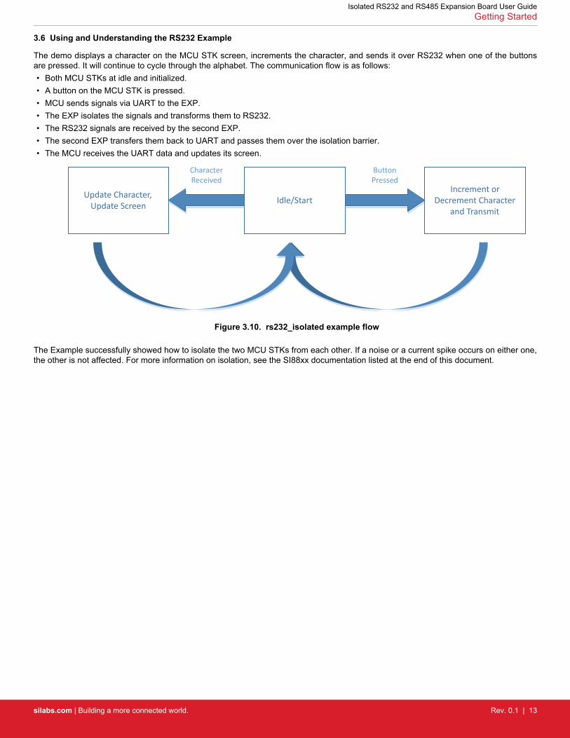
The demo displays a character on the MCU STK screen, increments the character, and sends it over RS232 when one of the buttonsare pressed. It will continue to cycle through the alphabet. The communication flow is as follows:• Both MCU STKs at idle and initialized.• A button on the MCU STK is pressed.• MCU sends signals via UART to the EXP.• The EXP isolates the signals and transforms them to RS232.• The RS232 signals are received by the second EXP.• The second EXP transfers them back to UART and passes them over the isolation barrier.• The MCU receives the UART data and updates its screen.
Idle/Start
Button Pressed
Increment or Decrement Character
and Transmit
Update Character, Update Screen
Character Received
Figure 3.10. rs232_isolated example flow
The Example successfully showed how to isolate the two MCU STKs from each other. If a noise or a current spike occurs on either one,the other is not affected. For more information on isolation, see the SI88xx documentation listed at the end of this document.
Isolated RS232 and RS485 Expansion Board User GuideGetting Started
silabs.com | Building a more connected world. Rev. 0.1 | 13
4. Relevant Documentation
The following documents are available on http://www.silabs.com.• EFM32 Wonder Gecko STK User Guide – User manual for the Wonder Gecko Starter Kit.• Si88x4x Quad Digital Isolators with DC-DC Converter Datasheet — Overview and characteristics of the Si88x4x series of isolators.• Si8640/Si8641/Si8642/Si8645 Low-Power Quad-Channel Digital Isolators Datasheet — Overview and characteristics of the Si864x
series of isolators.
Datasheet and support documentation can be accessed on the Silicon Labs website http://www.silabs.com or in Simplicity Studio underthe Document Index section.
Isolated RS232 and RS485 Expansion Board User GuideRelevant Documentation
silabs.com | Building a more connected world. Rev. 0.1 | 14

http://www.silabs.com
Silicon Laboratories Inc.400 West Cesar ChavezAustin, TX 78701USA
Smart. Connected. Energy-Friendly.
Productswww.silabs.com/products
Qualitywww.silabs.com/quality
Support and Communitycommunity.silabs.com
DisclaimerSilicon Labs intends to provide customers with the latest, accurate, and in-depth documentation of all peripherals and modules available for system and software implementers using or intending to use the Silicon Labs products. Characterization data, available modules and peripherals, memory sizes and memory addresses refer to each specific device, and "Typical" parameters provided can and do vary in different applications. Application examples described herein are for illustrative purposes only. Silicon Labs reserves the right to make changes without further notice and limitation to product information, specifications, and descriptions herein, and does not give warranties as to the accuracy or completeness of the included information. Silicon Labs shall have no liability for the consequences of use of the information supplied herein. This document does not imply or express copyright licenses granted hereunder to design or fabricate any integrated circuits. The products are not designed or authorized to be used within any Life Support System without the specific written consent of Silicon Labs. A "Life Support System" is any product or system intended to support or sustain life and/or health, which, if it fails, can be reasonably expected to result in significant personal injury or death. Silicon Labs products are not designed or authorized for military applications. Silicon Labs products shall under no circumstances be used in weapons of mass destruction including (but not limited to) nuclear, biological or chemical weapons, or missiles capable of delivering such weapons.
Trademark InformationSilicon Laboratories Inc.® , Silicon Laboratories®, Silicon Labs®, SiLabs® and the Silicon Labs logo®, Bluegiga®, Bluegiga Logo®, Clockbuilder®, CMEMS®, DSPLL®, EFM®, EFM32®, EFR, Ember®, Energy Micro, Energy Micro logo and combinations thereof, "the world’s most energy friendly microcontrollers", Ember®, EZLink®, EZRadio®, EZRadioPRO®, Gecko®, ISOmodem®, Micrium, Precision32®, ProSLIC®, Simplicity Studio®, SiPHY®, Telegesis, the Telegesis Logo®, USBXpress®, Zentri and others are trademarks or registered trademarks of Silicon Labs. ARM, CORTEX, Cortex-M3 and THUMB are trademarks or registered trademarks of ARM Holdings. Keil is a registered trademark of ARM Limited. All other products or brand names mentioned herein are trademarks of their respective holders.


