2008 MATE INTERNATIONAL ROV COMPETITIONTecHnical RepoRT
Ranger class“The DiveDog”
Submitted by: team: bluetec 2
blue Hills Regional technical School
team membeRS:
derek Lagasse- team Leader
Joseph Girouard- Pilot
dimitry bajeux
Rhiannon Swyers
dan Zaleski
Phil O’Garro
tim Zaleski
John macdonald
mentORS:dr. michael meyers manuel Cerquiera
Jill bearse
“Our ROV the DiveDog”
Team Blue Tec2
Table of conTenTs
Table of Contents
Abstract
Design Rationale - Frame - Control System - Video Camera -Tools - Tether - Propulsion
Major ChallengeTroubleshooting
Electrical Schematic
Budget/Expense ReportDonations
Future Improvements
Lessons Learned
Reflection StatementAcknowledgements
Research
Photo Gallery
AppendixA-ROV Exploded View- “the DiveDog”B-ROV Assembly Drawing 1C-ROV 3D Assembly Drawing 2
2
2
3
4
5
6
9
10
11
12
13-14
15-16
17-19
7-8
absTRacT
This technical report accurately describes our ROV (remotely operated vehicle), “The DiveDog” created by Team BlueTec from Blue Hills Regional Technical School located in Canton, Massachusetts, USA. Our goal as a team is to design, build and operate a ROV capable of completing the tasks described as part of the 2008 MATE International ROV Competition in a quick, efficient and affective manner. As a team we believe that we have designed a ROV capable of completing the mission.
This report will describe in detail our ROV, its specifications and theory of operation. Our report also describes challenges faced during design and testing, how we overcame these challenges and what we learned from the experience. We have also included a complete expense report, a description of improvements we plan to make in the future and a description of our experiences and those participants who helped us accomplish our goal.
3
2
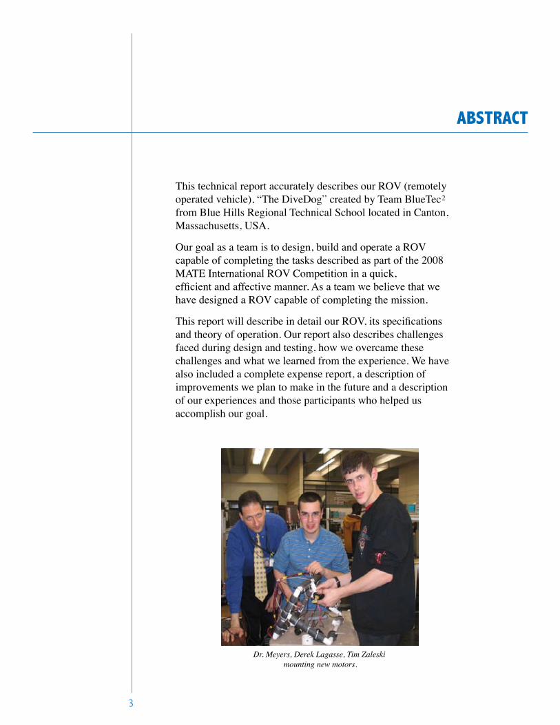
Dr. Meyers, Derek Lagasse, Tim Zaleski mounting new motors.
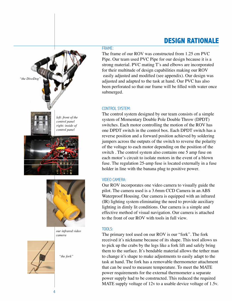
Design RaTionaleFRame: The frame of our ROV was constructed from 1.25 cm PVC Pipe. Our team used PVC Pipe for our design because it is a strong material. PVC mating T’s and elbows are incorporated for their multitude of design capabilities making our ROV easily adjusted and modified (see appendix). Our design was adjusted and adapted to the task at hand. Our PVC has also been perforated so that our frame will be filled with water once submerged.
COntROL SyStem: The control system designed by our team consists of a simple system of Momentary Double Pole Double Throw (DPDT) switches. Each motor controlling the motion of the ROV has one DPDT switch in the control box. Each DPDT switch has a reverse position and a forward position achieved by soldering jumpers across the outputs of the switch to reverse the polarity of the voltage to each motor depending on the position of the switch . The control system also contains one 5 amp fuse on each motorʼs circuit to isolate motors in the event of a blown fuse. The regulation 25-amp fuse is located externally in a fuse holder in line with the banana plug to positive power.
VideO CameRa: Our ROV incorporates one video camera to visually guide the pilot. The camera used is a 3.6mm CCD Camera in an ABS Waterproof Housing. Our camera is equipped with an infrared (IR) lighting system eliminating the need to provide auxiliarylighting in dimly lit conditions. Our camera is a simple and effective method of visual navigation. Our camera is attached to the front of our ROV with tools in full view.
tOOLS:The primary tool used on our ROV is our “fork”. The forkreceived it’s nickname because of its shape. This tool allows us to pick up the crabs by the legs like a fork lift and safely bring them to the surface. It’s bendable material allows the tether man to change it’s shape to make adjustments to easily adapt to the task at hand. The fork has a removable thermometer attachment that can be used to measure temperature. To meet the MATE power requirements for the external thermometer a separate power supply had to be constructed. This reduced the required MATE supply voltage of 12v to a usable device voltage of 1.5v.
4
“the DiveDog”
left: front of thecontrol panelright: inside ofcontrol panel
our infrared video camera
“the fork”
Design RaTionale
5
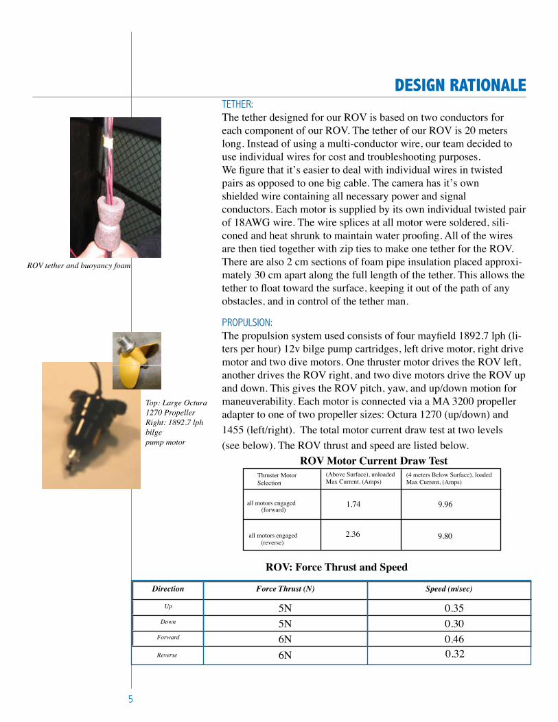
tetHeR:The tether designed for our ROV is based on two conductors for each component of our ROV. The tether of our ROV is 20 meters long. Instead of using a multi-conductor wire, our team decided to use individual wires for cost and troubleshooting purposes.We figure that itʼs easier to deal with individual wires in twisted pairs as opposed to one big cable. The camera has itʼs own shielded wire containing all necessary power and signalconductors. Each motor is supplied by its own individual twisted pair of 18AWG wire. The wire splices at all motor were soldered, sili-coned and heat shrunk to maintain water proofing. All of the wires are then tied together with zip ties to make one tether for the ROV. There are also 2 cm sections of foam pipe insulation placed approxi-mately 30 cm apart along the full length of the tether. This allows the tether to float toward the surface, keeping it out of the path of any obstacles, and in control of the tether man.
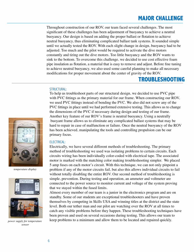
PROPuLSiOn: The propulsion system used consists of four mayfield 1892.7 lph (li-ters per hour) 12v bilge pump cartridges, left drive motor, right drive motor and two dive motors. One thruster motor drives the ROV left, another drives the ROV right, and two dive motors drive the ROV up and down. This gives the ROV pitch, yaw, and up/down motion for maneuverability. Each motor is connected via a MA 3200 propeller adapter to one of two propeller sizes: Octura 1270 (up/down) and 1455 (left/right). The total motor current draw test at two levels(see below). The ROV thrust and speed are listed below.
ROV Motor Current Draw Test
Thruster Motor Selection
9.96
9.802.36
1.74all motors engaged
all motors engaged
(Above Surface), unloadedMax Current, (Amps)
(4 meters Below Surface), loadedMax Current, (Amps)
(forward)
(reverse)
ROV tether and buoyancy foam
Top: Large Octura 1270 PropellerRight: 1892.7 lph bilge pump motor
Direction Force Thrust (N) Speed (m/sec)
Up 5N 0.35Down 5N 0.30
Forward 6N 0.46
ROV: Force Thrust and Speed
Reverse 6N 0.32
MajoR cHallengeThroughout construction of our ROV, our team faced several challenges. The most significant of these challenges has been adjustment of buoyancy to achieve a neutral buoyancy. Our design is based on adding the proper ballast or flotation to achieve neutral buoyancy, thus eliminating complicated ballast tank systems. It sounded simple until we actually tested the ROV. With each slight change in design, buoyancy had to be adjusted. Too much and the pilot would be required to activate the dive motors constantly and tiring out the dive motors. Too little buoyancy and the ROV wants to sink to the bottom. To overcome this challenge, we decided to use cost effective foam pipe insulation as flotation, a material that is easy to remove and adjust. Before fine tuning to achieve neutral buoyancy, we also used some careful planning to make all necessary modifications for proper movement about the center of gravity of the ROV.
6
TRoUblesHooTingStRuCtuRaL:To help us troubleshoot parts of our structural design, we decided to use PVC pipe with PVC fittings as the primary material for our frame. When constructing our ROV, we used PVC fittings instead of bending the PVC. We also did not screw any of the PVC fittings in place until we had performed extensive testing. This allows us to change the dimensions of the PVC if necessary during design and testing of our frame. Another key feature of our ROVʼs frame is neutral buoyancy. Using a neutrally buoyant frame allows us to eliminate any complicated ballast systems that may be hard to repair in case of malfunction or failure. Once the neutral buoyancy of the ROV has been achieved, manipulating the tools and controlling propulsion can be ourprimary focus.
eLeCtRiCaL:Electrically, we have several different methods of troubleshooting. The primary method of troubleshooting we used was isolating problems to certain circuits. Each circuits wiring has been individually color-coded with electrical tape. The associated motor is marked with the matching color making troubleshooting simpler. We placed 5 amp fuses on each motorʼs circuit. With this technique, we can not only pinpoint a problem if any of the motor circuits fail, but also this allows individual circuits to fail without totally disabling the entire ROV. Our second method of troubleshooting is simple, prevention. During testing and operation, an ammeter and voltmeter are connected to the power source to monitor current and voltage of the system proving that we stayed within the fused limits. Almost every member of our team is a junior in the electronics program and are on standby. Some of our students are exceptional troubleshooters and have proven themselves by competing in Skills USA and winning titles at the district and the state level. Both our tether man and our pilot are watching over the ROV at all times to catch any visible problems before they happen. These troubleshooting techniques have been proven and used on several occasions during testing. This allows our team to keep problems to a minimum and allow them to be located and repaired quickly.
temperature display
power supply for temperature sensor
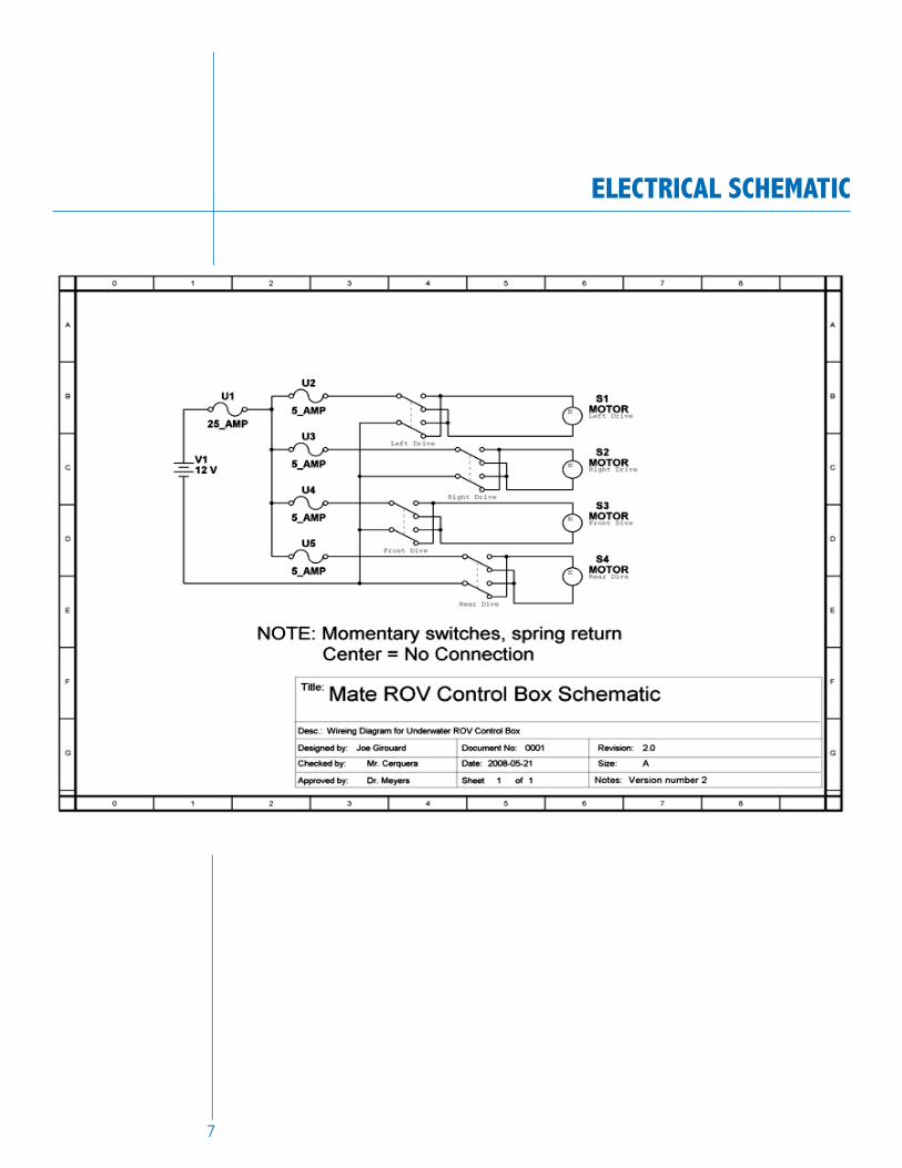
elecTRical scHeMaTic
7
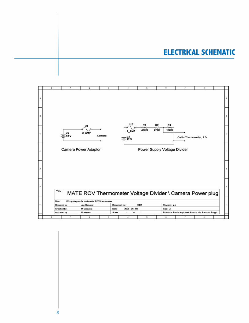
elecTRical scHeMaTic
8
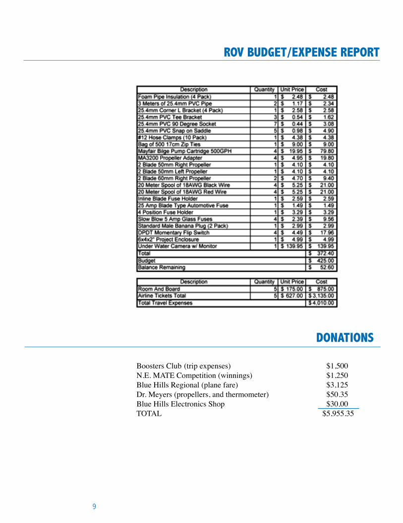
RoV bUDgeT/eXpense RepoRT
9
Boosters Club (trip expenses) $1,500N.E. MATE Competition (winnings) $1,250Blue Hills Regional (plane fare) $3,125Dr. Meyers (propellers, and thermometer) $50.35Blue Hills Electronics Shop $30.00TOTAL $5,955.35
DonaTions
fUTURe iMpRoVeMenTs
Our team built a ROV that is a work in progress. Our team has several ideas that we plan to implement in the future to improve upon the design, functionality and ease of use. One priority is to create more tools to accomplish the tasks at hand in the 2008 MATE International Competition. Our current tool “the fork” works great and is an adjustable design. We plan on creating at least a few more tools to test and at least one more tool for the competition. Our team is currently developing more tools and are up to the challenge of meeting the deadline.
Another improvement that we plan to implement in the near future is externally accessible fuses as well as a power indicator device. We think this would aid in our troubleshooting and add a level of safety to our system.
Another major improvement we would like to accomplish is theaddition of a precision thruster for precision movement of the ROV and its ability to aim for a target. Currently, our pilots agree that it does take some skill and practice to precisely control the ROV. While some other teams believe that a precision controller is the answer, we believe that a precision thruster using a similar system that we use now is a way to gain precise control without using complex software and circuits that could complicate troubleshooting.
And last but not least is the possibility of an additional camera to increase the field of vision.
10
lessons leaRneD
During the building and testing process of our teamʼs ROV, we learned a lot about underwater physics. Our team based our design upon neutral buoyancy. Although this became an additional challenge, our team gained more knowl-edge of physics underwater while trying to overcome this challenge. As we made several attempts to modify, adjust and test our ROV, we observed how changes in design changed the performance of our ROV. As we tested the ROV more, we began to interpret our observations and begin to see how the physics that effected our ROV worked.
One key example was our observations during testing our ROV controls. When attempting to aim for the target, we saw how long it took for the ROV to ex-ecute a maneuver and how long it took to stop. This minor detail was empha-sized when we allowed some of the freshman in our school test drive the ROV. Some had never driven anything like it before and not knowing how it was de-signed, it was easy for them to lose control over the ROV. “There are no brakes underwater,” as Derek Lagasse says.
Another lesson learned was how to manage our time, resources and how to function as a team. Teamwork was essential in this project, withouteveryones contributions we would not have succeeded thus far.
11
ReflecTion sTaTeMenT
As a team, we believe that being part of the 2008 MATE International ROVCompetition has brought us closer together and given us an opportunity toapply what we learn in electronics and engineering each day to something we can be proud of. “You can learn a lot about engineering, but until you actually build something, your missing a piece of the puzzle,” says Derek Lagasse. By coming together as a team, we have had the opportunity to share our knowledge and build a better ROV than any one of us could have on our own.
12
acknowleDgeMenTs
We would like to thank everyone who has made this possible:• The Marine Advanced Technology Education Center- for making this program possible• Mass Maritime - for hosting this yearʼs New England Regional MATE Competition• Blue Hills Regional - for all their help, support, and donations• The Blue Hills Adopt - a Shop Program• The Blue Hills Athletic Department - thanks for letting us use the school pool• The Engineering Department• Electronics Department• The BHR Shops - for their assistance Electrical Department HVAC Department Design and Visual Communication Department• The Administration• William Lagasse - for all of his help and support
Special Thanks to our Mentors Dr. Meyers Mr. Cerquera Ms. Bearse
ReseaRcH
13
ROV
The mid-ocean ridge is a system of undersea volcanoes that meander over the Earth. It is a continuous 60,000-kilometer seam that encircles the Earth. Mid-ocean ridges have many different shapes depending on how fast they are spread-ing, how active they are volcanically, and how much seismic activity is taking place. There are two types of mid-ocean ridges: fast-spreading and slow-spreading. Fast-spreading ridges like the northern and southern East Pacific Rise have smoother topography at the ridge crest, and look somewhat like domes. The East Pacific Rise moves at an average of 15 centimeters per year. Slow-spread-ing ridges like the Mid-Atlantic Ridge have large, wide, rift valleys, sometimes as wide as 10 to 20 kilometers and very rugged terrain at the ridge crest. The Mid-Atlantic Ridge moves at an average of 2.5 centimeters per yearFast-spreading ridges are “hotter,” meaning that more magma is present beneath the ridge axis, and that more volcanic eruptions occur. At slower spreading ridges, the seafloor when pulled cracks and breaks to form ridges and valleys. As the sheets of oceanic crust move away from the mid-ocean ridge, the rock is cooled and thus becomes heavier. Mid-ocean ridges do not form straight lines but are instead offset in many places by fracture zones. Fracture zones are thought to occur due to zones of weakness in the pre-existing continent before it was rifted apart. Most mid-ocean ridges are divided into hundreds of segments by fracture zones. Along the Mid-Atlan-tic Ridge, fracture zones occur at an average interval of 55 kilometers. As the Mid-Atlantic Ridge is some 16,000 kilometers long, it is divided by fracture zones into about 300 distinct segments. ROV’s are commonly used for research tasks very similar to the tasks featured in the 2008 MATE international ROV competition. On August 3-20 2007 the monetary bay aquarium research institute crewed a NOAA NeMO mission to map and study axial volcano. The crew climbed aboard the Woods Hole Ocean-ographic institute research vessel Atlantis. Atlantis is 274 foot vessel capable of carrying 59 crew members for a stay of 60 days. Atlantis is also the home of the famous submersible Alvin, renown for exploring the titanic. By day the crew deployed their main ROV Jason II to pick up instruments, samples, and use various tools to explore the chosen site. By night the crew used MBARI, an autonomous underwater vehicle (AUV) with mapping sonar, to map out the particular part of the ridge they are exploring. With this alternat-ing cycle of vehicles the crew can stud their environment 24/7 and get the most out of their expedition.
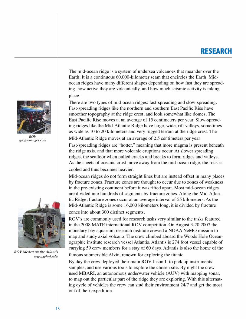
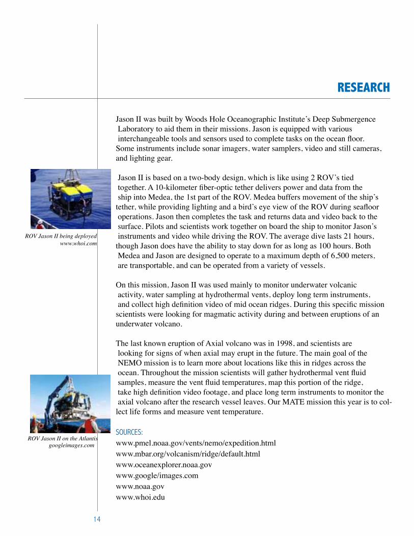
ROV Medea on the Atlantis www.whoi.edu
googleimages.com
14
ReseaRcH
Jason II was built by Woods Hole Oceanographic Institute’s Deep Submergence Laboratory to aid them in their missions. Jason is equipped with various interchangeable tools and sensors used to complete tasks on the ocean floor.Some instruments include sonar imagers, water samplers, video and still cameras, and lighting gear.
Jason II is based on a two-body design, which is like using 2 ROV’s tied together. A 10-kilometer fiber-optic tether delivers power and data from the ship into Medea, the 1st part of the ROV. Medea buffers movement of the ship’s tether, while providing lighting and a bird’s eye view of the ROV during seafloor operations. Jason then completes the task and returns data and video back to the surface. Pilots and scientists work together on board the ship to monitor Jason’s instruments and video while driving the ROV. The average dive lasts 21 hours, though Jason does have the ability to stay down for as long as 100 hours. Both Medea and Jason are designed to operate to a maximum depth of 6,500 meters, are transportable, and can be operated from a variety of vessels.
On this mission, Jason II was used mainly to monitor underwater volcanic activity, water sampling at hydrothermal vents, deploy long term instruments, and collect high definition video of mid ocean ridges. During this specific mission scientists were looking for magmatic activity during and between eruptions of an underwater volcano.
The last known eruption of Axial volcano was in 1998, and scientists are looking for signs of when axial may erupt in the future. The main goal of the NEMO mission is to learn more about locations like this in ridges across the ocean. Throughout the mission scientists will gather hydrothermal vent fluid samples, measure the vent fluid temperatures, map this portion of the ridge, take high definition video footage, and place long term instruments to monitor the axial volcano after the research vessel leaves. Our MATE mission this year is to col-lect life forms and measure vent temperature.
SOuRCeS:www.pmel.noaa.gov/vents/nemo/expedition.htmlwww.mbar.org/volcanism/ridge/default.htmlwww.oceanexplorer.noaa.govwww.google/images.comwww.noaa.govwww.whoi.edu
ROV Jason II being deployed www.whoi.com
ROV Jason II on the Atlantisgoogleimages.com
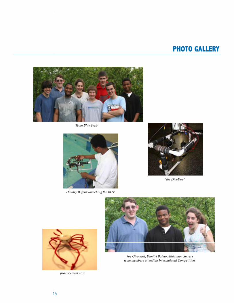
pHoTo galleRy
15
Team Blue Tech2
Dimitry Bajeux launching the ROV
“the DiveDog”
Joe Girouard, Dimitri Bajeux, Rhiannon Swyersteam members attending International Competition
practice vent crab
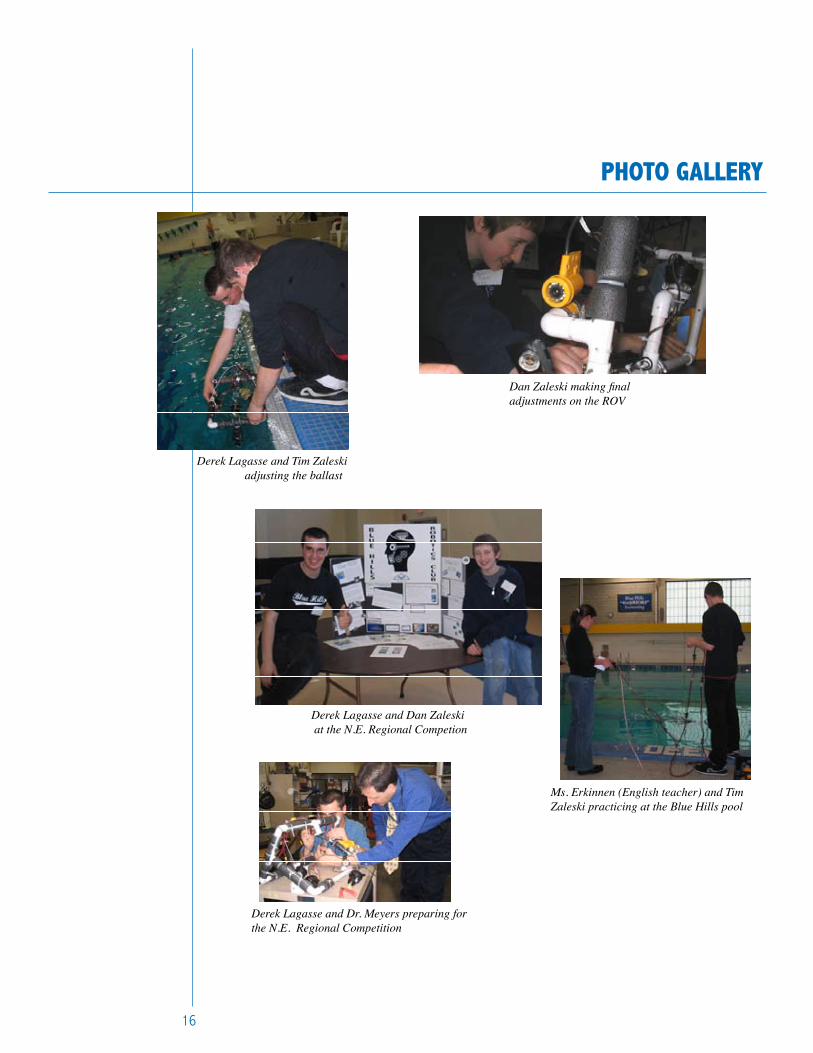
pHoTo galleRy
Dan Zaleski making final adjustments on the ROV
Derek Lagasse and Tim Zaleski adjusting the ballast
Derek Lagasse and Dan Zaleski at the N.E. Regional Competion
Ms. Erkinnen (English teacher) and Tim Zaleski practicing at the Blue Hills pool
Derek Lagasse and Dr. Meyers preparing for the N.E. Regional Competition
16
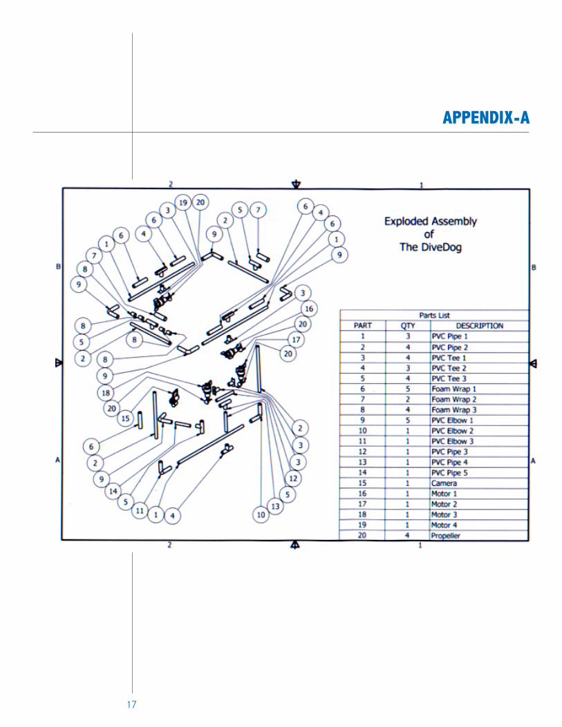
appenDiX-a
17
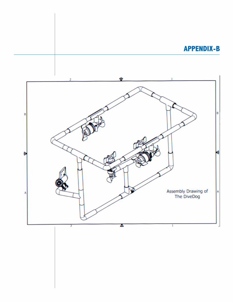
appenDiX-b
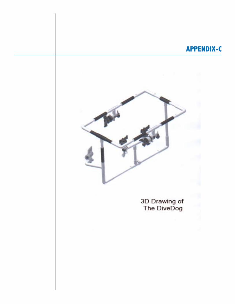
appenDiX-c


