TS 5C - The Quality of Measurements David Martin
Instrument Calibration at the ESRF (3910)
FIG Congress 2010
Facing the Challenges – Building the Capacity
Sydney, Australia, 11-16 April 2010
1/11
Instrument Calibration at the ESRF
David MARTIN, France
Key words: calibration, laser tracker, theodolite, total station
SUMMARY
The European Synchrotron Radiation Facility (ESRF) is an accelerator laboratory located in
Grenoble – France. It is a joint facility supported and shared by 18 European countries. The
ESRF operates the most powerful synchrotron radiation source in Europe. Each year several
thousand researchers travel to Grenoble where they work in a first-class scientific
environment to conduct exciting experiments at the cutting edge of modern science.
The ALignment and GEodesy (ALGE) group is responsible for the installation, control and
periodic realignment of the accelerators and experiments at the ESRF. Alignment tolerances
are typically less than one millimetre and often in the order of several micrometers over the
approximate 1 km accelerator network. Typically, least squares survey network calculations
give distance and angle residual standard deviations of 0.1 mm and 0.5 arc second
respectively. The semi-major axis of the absolute error ellipses are less than 0.15 mm at the
95% confidence level.
To help obtain these results, the ESRF has and continues to develop calibration techniques for
high precision Robotic Total Stations (RTSs) and Laser Trackers (LTs). Electronic Distance
Meters (EDM) incorporated into RTSs and Interferometric and Absolute Distance Meters
(IFMs and ADMs) used in LT instruments are calibrated on the 50 m long Distancemeter
Calibration Bench (DCB). Recently two instrument standards, the Horizontal Circle
Comparator (HCC) and the Vertical Circle Comparator (VCC), were developed to calibrate
horizontal and vertical angles measured by RTS and LT instruments. These three instrument
standards are accredited by COFRAC1 under the ISO/IEC 17025:2005 General requirements
for the competence of testing and calibration laboratories standard.[1]
This paper will present these standards and calibration results of LT and RTS instruments
calibrated on them.
1 The HCC and VCC are in the process of final COFRAC accreditation.
TS 5C - The Quality of Measurements David Martin
Instrument Calibration at the ESRF (3910)
FIG Congress 2010
Facing the Challenges – Building the Capacity
Sydney, Australia, 11-16 April 2010
2/11
Instrument Calibration at the ESRF
David MARTIN, France
1. INTRODUCTION
Robotic Total Stations (RTSs) 2
and Laser Trackers (LTs) are used extensively in large scale
metrology (LSM). They determine three dimensional coordinates of a point by measuring two
orthogonal angles (nominally horizontal and vertical) and a distance to a corner cube
reflector; typically a spherically mounted retro-reflector (SMR).
LSM covers fields that require very high precision alignment over relatively large areas and
volumes. Examples of LSM include particle accelerator alignment and aircraft, ship and car
manufacture. [2, 3] The field of particle accelerator alignment is unique in so far as it overlaps
both the fields of metrology and traditional surveying and geodesy. Standard measurement
precision is typically sub-millimetric over distances ranging between several hundred metres
up to nearly 30 km. Extremely specialised techniques and instruments are needed to guarantee
that these requirements can be met. [4, 5]
2. ALIGNMENT AND CALIBRATION AT THE ESRF
For the ESRF accelerators and beam lines to work correctly, alignment is of critical
importance. The ESRF ALignment and GEodesy (ALGE) group is responsible for the
installation, control and periodic realignment of the accelerators and experiments. Alignment
tolerances are typically less than one millimetre and often in the order of several micrometers.
Distance and angle residual standard deviations issued from the 842 metre long accelerator
network are in the order of 0.1 mm and 0.5 arc-seconds respectively. Absolute error ellipses
are smaller than 0.15 mm at the 95% confidence level. [6]
To help obtain these results, the ESRF has and continues to develop calibration techniques for
high precision motorized RTS instruments. This type of instrument is the workhorse for all
precision work made at the ESRF. At present, the ESRF Alignment and Geodesy group
provides a full calibration suite for the calibration of distances and angles issued from RTSs
and LTs. Distances are calibrated on the Distance Meter Calibration Bench (DCB). Horizontal
angles are calibrated using the Horizontal Circle Comparator (HCC), and vertical angles are
calibrated against the Vertical Angle Comparator (VCC).[7]
2 Robotic Total Stations are total stations (i.e. a theodolite with an integrated distance meter) equipped with an
automatic target recognition (ATR) system. They provide a degree of remote control of the instrument. For
example, a survey operator can control the RTS from a distance using a wireless radio device. The operator
holds the reflector and controls the total station from the observed point. At the ESRF, the RTS is controlled
from a laptop computer to follow a pre-programmed measurements series.

TS 5C - The Quality of Measurements David Martin
Instrument Calibration at the ESRF (3910)
FIG Congress 2010
Facing the Challenges – Building the Capacity
Sydney, Australia, 11-16 April 2010
3/11
2.1 The Distance Meter Calibration Bench
At the ESRF, distances are calibrated against the 52 m long DCB (refer to Figure 1). Since
February 2001, this bench has been accredited under ISO/IEC 17025 for the calibration of
EDM’s by COFRAC, (COmité FRançais pour l'ACcréditation) the French National
accreditation body.
An accredited interferometer is installed on a fixed pillar at one end of the bench and the
instrument to be measured (RTS or LT) is installed on a fixed pillar or heavy tripod at the
other end. The interferometer and instrument reflector are installed on a servo-controlled
carriage. A calibration is made by first determining the zero error of the instrument reflector
pair and then by moving the servo-carriage along the bench and comparing the displacements
measured by the RTS or LT and the interferometer.
Figure 1 Schematic of the ESRF calibration bench. Zoom a) is the instrument station; zoom
b) the servo carriage with the instrument and interferometer reflectors and zoom c) the
interferometer station. After the zero error has been determined the servo carriage is moved in
10 cm intervals from 2 m to 50 m to determine the instrument cyclic (bias) error.
The bench is equipped with an accredited meteorological station which measures temperature,
pressure and humidity. Additional temperature sensors are installed at regular intervals along
the length of the bench to improve corrections for the variations in refraction along the line of
sight. EDM calibrations can be made between 1.9 and 50 m with an expanded uncertainty3
( )2k = of0.07 mm 0.76q+ ; and from 1.9 to 113 m with and expanded uncertainty
of0.10 mm 0.74q+ . Here, q is the instrument resolution. It is 0.1 mm in the case of the
3 The notion of expanded uncertainty is discussed in the Guide to the Expression of uncertainty in Measurement
(GUM).
TS 5C - The Quality of Measurements David Martin
Instrument Calibration at the ESRF (3910)
FIG Congress 2010
Facing the Challenges – Building the Capacity
Sydney, Australia, 11-16 April 2010
4/11
RTSs used at the ESRF. Therefore the expanded uncertainty for 50 m and 113 m calibrations
are 0.15 mm and 0.17 mm respectively. In 2006 the ESRF accreditation was extended to laser
trackers. The uncertainty ( )2k = for the calibration of LT absolute distance meters (ADMs)
and interferometric distance meters (IFMs) over the range of 0.2 m to 48.2 m is 42 µm. [8-11]
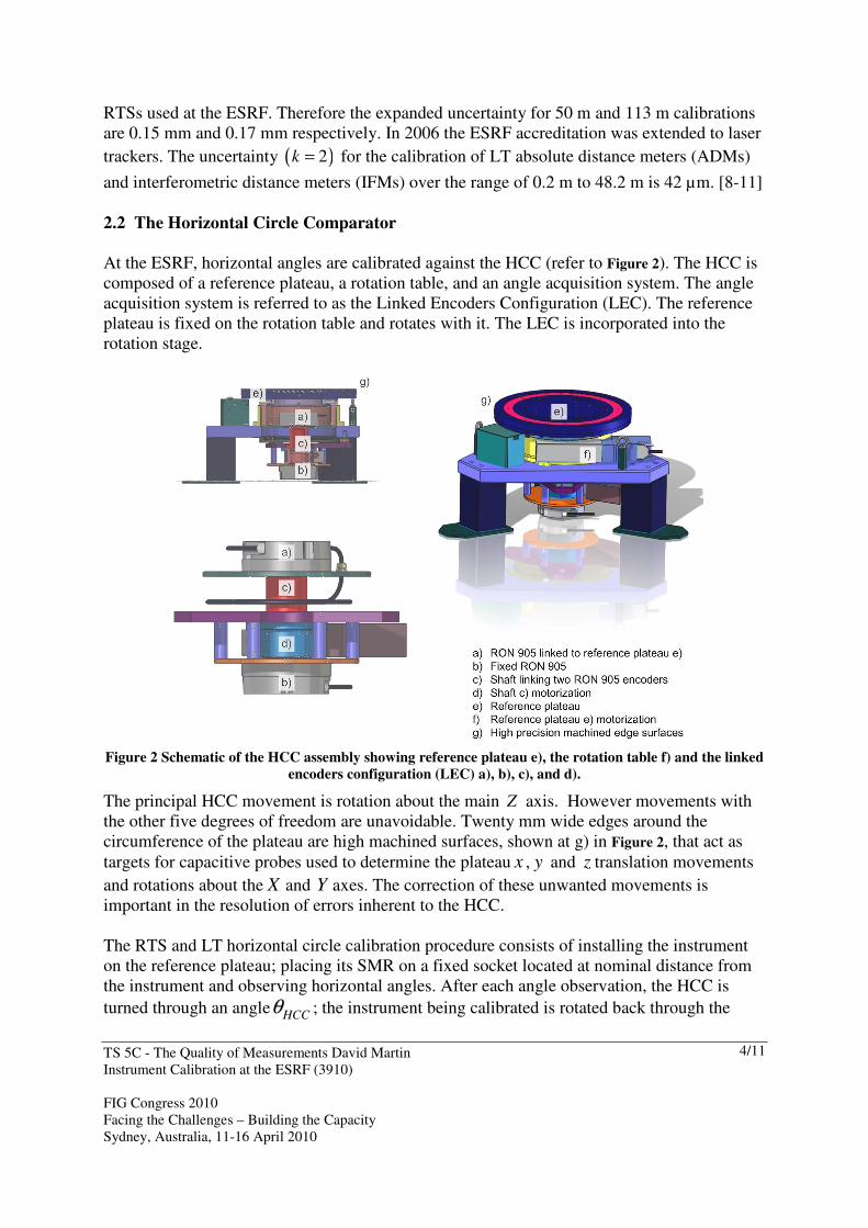
2.2 The Horizontal Circle Comparator
At the ESRF, horizontal angles are calibrated against the HCC (refer to Figure 2). The HCC is
composed of a reference plateau, a rotation table, and an angle acquisition system. The angle
acquisition system is referred to as the Linked Encoders Configuration (LEC). The reference
plateau is fixed on the rotation table and rotates with it. The LEC is incorporated into the
rotation stage.
Figure 2 Schematic of the HCC assembly showing reference plateau e), the rotation table f) and the linked
encoders configuration (LEC) a), b), c), and d).
The principal HCC movement is rotation about the main Z axis. However movements with
the other five degrees of freedom are unavoidable. Twenty mm wide edges around the
circumference of the plateau are high machined surfaces, shown at g) in Figure 2, that act as
targets for capacitive probes used to determine the plateau x , y and z translation movements
and rotations about the X and Y axes. The correction of these unwanted movements is
important in the resolution of errors inherent to the HCC.
The RTS and LT horizontal circle calibration procedure consists of installing the instrument
on the reference plateau; placing its SMR on a fixed socket located at nominal distance from
the instrument and observing horizontal angles. After each angle observation, the HCC is
turned through an angle HCCθ ; the instrument being calibrated is rotated back through the

TS 5C - The Quality of Measurements David Martin
Instrument Calibration at the ESRF (3910)
FIG Congress 2010
Facing the Challenges – Building the Capacity
Sydney, Australia, 11-16 April 2010
5/11
same nominal angle RTSθ− , and the observation procedure is repeated. The calibration
consists of comparing the differences between the HCC angle readings and RTS or LT
horizontal circle observations. The procedure is illustrated in Figure 3. Any angle displacement
over 360 degrees can be investigated.
Figure 3 Observation procedure using the HCC.
2.3 The Linked Encoders Configuration
The HCC angle reference system is the LEC (Figure 2). The LEC consists of two Heidenhain
RON 905 angle encoders mounted in juxtaposition. The body of one RON 905 is fixed to the
main support assembly and does not move. The body of the second RON 905 is fixed to the
main plateau and rotates with it. The two RON 905 encoders (rotors) are rigidly connected
together in a precision alignment shaft assembly. The shaft and encoders are rotated
continuously by a high-performance precision rotation stage (shown c) in Figure 2). The two
RON 905 encoder positions are read out simultaneously and continuously. The LEC is used to
reduce the influence of residual RON 905 encoder errors. [12-15] Comparative small angle
tests made between the LEC and high precision capacitive probes measuring rotational
movements of a 1 m long bar show that the LEC uncertainty remains below 0.05 arc seconds.
The HCC has been examined by COFRAC and is awaiting final accreditation. The expanded
uncertainty ( )2k = for HCC calibrations of RTS and LT horizontal circles is 1 arc second.4
2.4 The VCC
4 As part of the accreditation procedure, an inter-laboratory comparison between the ESRF and the French
National Metrology Institute, the Laboratoire National d'Essais (LNE) using a 12 sided polygon mirror was
made. Values were compared using n
E numbers. The maximum n
E number was determined to be 0.44. Values
of 1n
E < provide objective evidence that the estimate of uncertainty is consistent with the definition of
expanded uncertainty given in the GUM.
TS 5C - The Quality of Measurements David Martin
Instrument Calibration at the ESRF (3910)
FIG Congress 2010
Facing the Challenges – Building the Capacity
Sydney, Australia, 11-16 April 2010
6/11
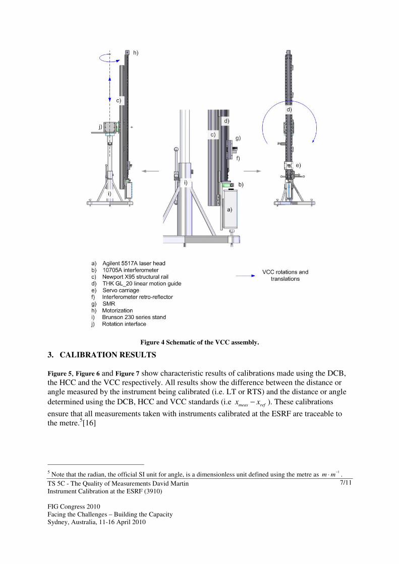
The VCC is composed of a motorized 2.5 m long linear motion guide with carriage fixed to a
3 m aluminium structural rail and an interferometer system (refer to Figure 4). The
interferometer system is positioned at one end of the rail while the motorisation driving the
carriage is at the opposite end. Its reflector is placed on the carriage. The full system is placed
on a heavy duty adjustable height stand. The VCC system is interfaced to the stand with a
system which permits it to be rotated in any orientation. When the VCC, a multipurpose tool,
is oriented vertically it can be used to calibrate the vertical circles of RTSs and LTs.
Whereas it is important to examine the horizontal circle over the full 360°, this constraint is
generally relaxed with vertical circles. First, no instrument available on the market is capable
of observing a target directly over the full 360° vertical circle. For example its base prevents it
from reading angles between approximately 150° and 210°. Often taking vertical readings
near the zenith (i.e. 0º) is difficult as well. For the most part, the typical working range of the
vertical circle of LTs and RTSs is within ±45° of the horizontal (i.e. vertical circle readings of
90°±45° and 270°±45°).
The VCC calibration procedure compares the SMS vertical circle readings with the vertical
displacements of its SMR. These vertical displacements are measured by the interferometer
system installed on the VCC. The determination of the vertical reference angle requires the
simultaneous measurement of the distance between the instrument being calibrated and the
VCC. Provided that the instrument (RTS or LT) distance meter is calibrated on the ESRF
DCB, these distances are traceable with an assigned uncertainty and coverage factor.
The VCC has been examined by COFRAC and is awaiting final accreditation. The expanded
uncertainty ( )2k = for VCC calibrations of RTS and LT horizontal circles is
1.65 arc seconds.
TS 5C - The Quality of Measurements David Martin
Instrument Calibration at the ESRF (3910)
FIG Congress 2010
Facing the Challenges – Building the Capacity
Sydney, Australia, 11-16 April 2010
7/11
Figure 4 Schematic of the VCC assembly.
3. CALIBRATION RESULTS
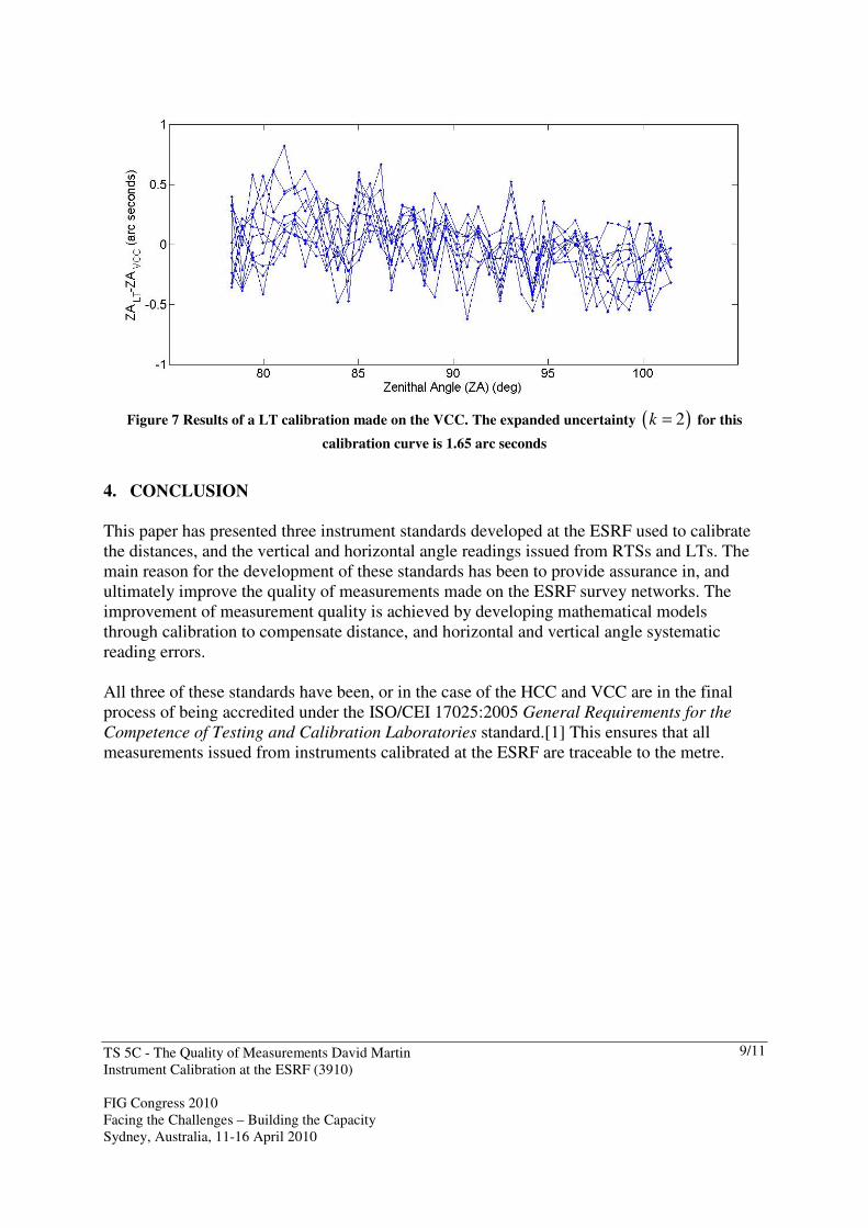
Figure 5, Figure 6 and Figure 7 show characteristic results of calibrations made using the DCB,
the HCC and the VCC respectively. All results show the difference between the distance or
angle measured by the instrument being calibrated (i.e. LT or RTS) and the distance or angle
determined using the DCB, HCC and VCC standards (i.e meas ref
x x− ). These calibrations
ensure that all measurements taken with instruments calibrated at the ESRF are traceable to
the metre.5[16]
5 Note that the radian, the official SI unit for angle, is a dimensionless unit defined using the metre as
1m m
−
⋅ .

TS 5C - The Quality of Measurements David Martin
Instrument Calibration at the ESRF (3910)
FIG Congress 2010
Facing the Challenges – Building the Capacity
Sydney, Australia, 11-16 April 2010
8/11
Figure 5 Typical IFM, ADM and EDM distance error curves derived from calibrations made on the ESRF
DCB. The ADM and IFM curves are from three different instruments and manufacturers. The expanded
uncertainties ( )2k = for these calibration curves are 0.042 mm for the IFM and ADM curves and 0.15
mm for the EDM curve.
Figure 6 Results of a LT calibration made on the HCC. The heavy red line is a model for the horizontal
angles issued from a LT. The RMSE of this model is 1.07 arc seconds. The expanded uncertainty ( )2k =
for this calibration curve is 1.0 arc seconds
TS 5C - The Quality of Measurements David Martin
Instrument Calibration at the ESRF (3910)
FIG Congress 2010
Facing the Challenges – Building the Capacity
Sydney, Australia, 11-16 April 2010
9/11
Figure 7 Results of a LT calibration made on the VCC. The expanded uncertainty ( )2k = for this
calibration curve is 1.65 arc seconds
4. CONCLUSION
This paper has presented three instrument standards developed at the ESRF used to calibrate
the distances, and the vertical and horizontal angle readings issued from RTSs and LTs. The
main reason for the development of these standards has been to provide assurance in, and
ultimately improve the quality of measurements made on the ESRF survey networks. The
improvement of measurement quality is achieved by developing mathematical models
through calibration to compensate distance, and horizontal and vertical angle systematic
reading errors.
All three of these standards have been, or in the case of the HCC and VCC are in the final
process of being accredited under the ISO/CEI 17025:2005 General Requirements for the
Competence of Testing and Calibration Laboratories standard.[1] This ensures that all
measurements issued from instruments calibrated at the ESRF are traceable to the metre.
TS 5C - The Quality of Measurements David Martin
Instrument Calibration at the ESRF (3910)
FIG Congress 2010
Facing the Challenges – Building the Capacity
Sydney, Australia, 11-16 April 2010
10/11
REFERENCES
1. ISO, ISO/CEI 17025:2005 General Requirements for the Competence of Testing and Calibration
Laboratories. Second edition ed. 2005: International Organization for Standardization.
2. Estler, W.T., et al., Large-scale metrology - An update. CIRP Annals Manufacturing Technology
2002. 51(2): p. 587-609.
3. Peggs, G.N., et al., Recent Developments in Large Scale Dimensional Metrology. Proceedings of the
Institution of Mechanical Engineers, Part B: Journal of Engineering Manufacture 2009. 223(6): p. 571-
595.
4. Mayoud, M. Large Scale Metrology for Research and Industry – Application to Particle Accelerators
and Recent Developments. in FIG Working Week 2004 2004. Athens: FIG.
5. Martin, D. Review of Accelerator Alignment. in XXIV FIG International Congress. 2010. Sydney,
Australia.
6. Martin, D. Instrumentation and Survey Networks at the ESRF. in Eighth International Workshop on
Accelerator Alignment. 2004. CERN, Geneva Switzerland.
7. Martin, D. and D. Chetwynd. Angle calibration of robotic total stations and laser trackers. in XIX
IMEKO World Congress: Fundamental and Applied Metrology. 2009. Lisbon, Portugal: IMEKO.
8. Martin, D., A Modern Calibration Bench: Calibrating Survey Instruments. GIM International, 2007.
21(8): p. 21-23.
9. COFRAC. ANNEXE TECHNIQUE à l'attestation d'accréditation (convention n° 1 343) Norme NF EN
ISO/CEI 17025 v2005. 2008 Available from: www.cofrac.fr.
10. Martin, D. Calibration of Total Stations Instruments at the ESRF. in XXIII FIG International Congress.
2006. Munich, Germany.
11. JCGM, ed. Evaluation of measurement data — Guide to the expression of uncertainty in measurement.
ed. J.C.f.G.i. Metrology. 2008, BIPM: Sèvres.
12. Palmer, E.W., Goniometer with Continuously Rotating Gratings for Use as an Angle Standard.
Precision Engineering-Journal of the American Society for Precision Engineering, 1988. 10(3): p. 147-
152.
13. Leleu, S., J.M. David, and G.P. Vailleau. La Mesure des Angles au BNM-LNE - Cretion d'une Nouvelle
Reference de Mesure Angulaire. in Congrès International de Métrologie 2005. 2003. Toulon.
14. Martin, D. The Analysis of Parasitic Movements on a High Precision Rotation Table. in MEDSI 2006.
2006. Himeji Japan.
15. Martin, D. and D. Chetwynd. High precision angle calibration of robotic total stations and laser
trackers. in 5th International Symposium on Instrumentation Science and Technology. 2008. Shenyang,
China.
16. BIPM, The International System of Units (SI). 2006, Comité International des Poids et Mesures
BIOGRAPHICAL NOTES
David Martin is head of the ESRF Alignment and Geodesy Group. He holds an MSc in Land
Surveying from the Department of Geomatic Engineering, University College London and a
PhD in Engineering from the University of Warwick in the United Kingdom. He is the chair
of FIG Standards Network and FIG Working Group 5.1 Standards, Quality Assurance and
Calibration. He has published a number of papers concerning accelerator alignment, survey
instrument calibration and hydrostatic levelling systems.
CONTACTS
David Martin
European Synchrotron Radiation Facility
BP220, 38043 Grenoble CEDEX 9
FRANCE

TS 5C - The Quality of Measurements David Martin
Instrument Calibration at the ESRF (3910)
FIG Congress 2010
Facing the Challenges – Building the Capacity
Sydney, Australia, 11-16 April 2010
11/11
Email: [email protected]
Web site: http://www.esrf.eu


