
VHCEnergy Recovery Ventilators with Enthalpy Wheels and Integrated Heating and Cooling
Installation, Operation and Maintenance Instructions Manual
Capacity: 800 to 5,500 cfmModel: VHC-36, VHC-42, VHC-50
©2012 Venmar CES Inc.
IMpoRtantThe use of this appendix is specifically intended for a qualified installation and service agency. A qualified in-stallation and service agency must perform all installation and service of these appliances.
FoR YouR SaFEtYWhat to do if you smell gas:
1. Do not touch electrical switches or use any phone in the building.
2. Extinguish any open flame.3. Leave the building immediately.4. Immediately call gas supplier.
WaRnIngImproper installation, adjustment, alteration, service or maintenance can cause injury or death. Read the instal-lation, operation and maintenance instructions in this appendix thoroughly before installing or servicing this equipment.
!

vces-vHc-iom-1 – vHc-36, 42 & 50 2
Nomenclature.......................................................................................................................................................................3Safety.Considerations..........................................................................................................................................................4General.Information............................................................................................................................................................4
Unit.Application.Limitations.........................................................................................................................................4Installation............................................................................................................................................................................4
Unit.Location.Requirements..........................................................................................................................................4Roofcurbs.Supplied.by.Venmar.CES.(External.Applications.Only)..............................................................................5Roofcurbs.Supplied.by.Others.......................................................................................................................................6Rigging.and.Placing.the.Unit........................................................................................................................................6Field.Fabricated.Ductwork............................................................................................................................................6Hood.Installation...........................................................................................................................................................7Access.Panels..................................................................................................................................................................7Internal.Packaging.........................................................................................................................................................7Electrical.Connections....................................................................................................................................................8Coil.Connections............................................................................................................................................................9Gas.Connections.............................................................................................................................................................9Water.Source.Heat.Pump.(WSHP).Water.Piping.and.Connections...........................................................................10Condensate.Drain.Trap................................................................................................................................................10
Start-up...............................................................................................................................................................................11Pre.Start-up.Procedure................................................................................................................................................11Start-up.Procedure.......................................................................................................................................................11Optional.Controls.and.Accessory.Sequence.and.Interlocks.......................................................................................12Frost.Control.................................................................................................................................................................13Airflow.Balancing........................................................................................................................................................14
Service.................................................................................................................................................................................15Quarterly.Maintenance...............................................................................................................................................15Annual.Maintenance...................................................................................................................................................15Coils...............................................................................................................................................................................15Testing.and.Replacement.of.the.Damper.Actuator...................................................................................................16Motor.and.Blower.Removal.–.Down,.Side.and.End.Supply/Exhaust.........................................................................16Motor.and.Blower.Service.–.Down,.Side.and.End.Supply/Exhaust...........................................................................16Motor.Removal.–.Gas.Units.and.Top.Supply/Exhaust................................................................................................17Blower.Removal.–.Gas.Units.and.Top.Supply/Exhaust...............................................................................................17Motor.and.Blower.Service.–.Gas.Units.and.Top.Supply/Exhaust...............................................................................17Belt.Tension.Adjustment.............................................................................................................................................18Plenum.Fan.and.Motor.Removal................................................................................................................................18Plenum.Fan.and.Motor.Service...................................................................................................................................19Cassette.Removal.........................................................................................................................................................19Cassette.Service............................................................................................................................................................20
Appendix.A:.Service.Clearance.Dimensions......................................................................................................................21Appendix.B:.Hood.Installation..........................................................................................................................................25Appendix.C:.Rigging.Drawing...........................................................................................................................................26Appendix.D:.Equipment.Data...........................................................................................................................................27Appendix.E:.Electrical.Data...............................................................................................................................................28Appendix.F:.Terminal.Control.Diagrams..........................................................................................................................32Appendix.G:.Standard.Field.Wiring.(FW).Terminals........................................................................................................35Appendix.H:.Temperature.Rise.Over.Gas.Furnace...........................................................................................................37Appendix.I:.In-shot.Gas.Burner.Information.for.2:1,.4:1.and.On/Off.............................................................................39Appendix.J:.VHC-36,.42.and.50.Start-up.Report.and.Checklist.......................................................................................48Appendix.K:.Troubleshooting...........................................................................................................................................52Appendix.L:.Electric.Heating.Coil.and.Controls.Information..........................................................................................54Appendix.M:.Water.Line.Field.Mounted.Options.and.Accessories.................................................................................56Appendix.N:.Enthalpy.Wheel.Pressure.Drop.vs..Flow.Formulae.and.Curves..................................................................64
Table of Contents
Manufacturer reserves the right to discontinue or change specifications or designs without notice or obligation.

vces-vHc-iom-1 – vHc-36, 42 & 50 3
Nomenclature
VHC-XX
Ventilator with heating and cooling
Nominal wheel diameter– 36– 42– 50
©Venmar CES Inc. 2012. All rights reserved throughout the world.
Illustrations cover the general appearance of Venmar CES products at the time of publication and Venmar CES reserves the right to make changes in design and construction at any time without notice.
™® The following are trademarks or registered trademarks of their respective companies: Venmar Select from Venmar CES, Variable Refrigerant Control (VRC) from Venmar CES and Tefzel from DuPont.
vces-vHc-iom-1 – vHc-36, 42 & 50 4
Safety Considerations
General Information
Unit.Application.Limitations
InstallationUnit.Location.Requirements
Warning, Caution and Important notes appear through-out this manual in specific and appropriate locations to alert Installing Contractors and maintenance or service personnel of potential safety hazards, possible equipment damage or to alert personnel of special procedures or in-structions that must be followed as outlined below.
Hazards may exist within this equipment because it con-tains electrical and numerous moving components. Only qualified service personnel should install or service this equipment. Untrained personnel may perform basic main-tenance such as maintaining filters. Observe precautions marked in literature and on labels attached to the unit. Follow all safety codes.
These ventilators can provide 100% outdoor air ventilation or, depending on options selected, varying amounts of recirculation between the exhaust and supply airstreams. The VHCs use an enthalpy wheel for total energy recov-ery which provides superior efficiency in hot and humid climates. These models are also effective in cold climates and use various types of frost control or defrost to ensure
proper operation when the outside temperatures are ex-tremely low. Units intended for rooftop installations must be installed on a factory or field supplied roofcurb. This manual contains information on optional components that may or may not be included with this unit. Refer to the submittals for options that pertain to this unit.
Using Venmar CES units for temporary ventilation during construction constitutes a violation of Venmar CES war-ranty terms which indicate that the unit warranty would be void “…if equipment is misapplied or if any alterations are made to the basic design or operating requirements as listed on the original order and shipped from the factory
unless approval is received in writing from Venmar CES” Fine dust, larger particulate matter, solvents, varnishes and other chemicals may cause filter clogging and elevated cabinet pressures, higher power consumption and pos-sible irreparable damage to the desiccant material of the enthalpy wheel, which could reduce energy recovery per-formance of the wheel and also reduce the heat transfer effectiveness of other components. Potential damages include, but are not limited to, these examples.
Consult local building codes and electrical codes for spe-cial installation requirements and note additional require-ments listed in this manual. In choosing the installation location of the unit, consider the following factors:
• The unit should be installed to allow easy access for maintenance and for systems operation. See the ser-vice clearance dimensions in Appendix A.
• When possible, mount the unit over an unused area such as a hallway. Although fans and motors are mounted on vibration isolators or are dynamically
CautIonIdentifies an instruction which, if not followed, might se-verely damage the unit, its components, the assembly or final installation.
IMpoRtantIndicates supplementary information needed to fully complete an instruction or installation.
WaRnIngIdentifies an instruction which, if not followed, might cause serious personal injuries including possibility of death.
!
WaRnIngVenmar CES equipment is not designed to be used for tem-porary heating, cooling and/or ventilation during construction.
!
WaRnIngDisconnect the main power switch to the unit before per-forming service or maintenance. Electric shock can cause personal injury or death.
!

vces-vHc-iom-1 – vHc-36, 42 & 50 5
balanced, the unit will be even less perceptible if po-sitioned away from busy offices.
• Locate the unit in an area requiring the least amount of ductwork and direction changes to allow optimum performance, to reduce pressure loss and to use less electricity to achieve proper ventilation. Ductwork must be in accordance with ducting mechanical rules to prevent sound issues and system effects.
• The fresh air intake hood must be positioned away from sources of contamination such as hot chimneys or kitchen exhaust vents.
• Fresh air intake must also be positioned in a direction opposite to that of prevailing winds to reduce entry of snow or rain.
• The unit should be mounted on a level foundation to allow condensation to flow into internal drains. The foundation must provide adequate continuous sup-port to minimize deflection of the unit base frame to not more than 1/16” [1.6 mm] over entire length. In addition to these recommendations, a Structural En-
gineer must be involved to properly size supporting structural elements.
• When mounting the unit indoors, if drain connec-tions are required, mount the unit on a housekeep-ing pad of sufficient height to allow for drain trap height and condensate lines to slope toward the building drain.
• When mounting the unit on a roofcurb check the height from the finished roof to the bottom of the intake hood. Consult with Local Authorities or your building code for minimal intake hood height for the water-tight height from and above the finished roof and in snow prone areas, the buildup of snow, to de-termine the height of the roofcurb. Venmar CES op-tional roofcurbs measure 18” [457 mm] in height. If additional height is required from the finished roof to the top of the roofcurb, to the bottom of the intake hood or if other than level, custom height roofcurbs must be ordered.
Roofcurbs supplied by Venmar CES should be mounted as follows:
• The roofcurb is shipped knocked-down with assem-bly hardware and instructions provided. The roofcurb must be field erected, assembled and set in place by the Installing Contractor.
• Roofcurb dimensions are submitted with the unit mechanical drawings which can also be found in the unit control panel pocket or by calling Technical Sup-port personnel from the Venmar CES factory.
• After the roofcurb has been assembled, ensure that the roofcurb dimensions suit the unit for which it is designated.
• The cross members must be positioned as per the roofcurb drawing to properly support the ductwork plenums for bottom vertical return and supply con-nections and for stability.
• Ensure that the assembled roofcurb is square, plumb and level to within 1/16” [1.6 mm] over the entire length. The building structure must provide continu-ous structural support to the full perimeter of the roofcurb and all cross members requiring support. The roofcurb may be shimmed as required to provide continuous support.
• The roofcurb must be fastened to the building structure.• The Installing Contractor is responsible for making the
roofcurb water-tight by caulking all roofcurb joints.
Roofcurbs.Supplied.by.Venmar.CES.(External.Applications.Only)
IMpoRtantThe following items must be completed prior to setting the unit on the roofcurb:
• The roofcurb roofing must be completed including insulation, cant strip, flashing and counter-flashing.
• Vertical ductwork must be attached to the roofcurb cross members and building structure, not to the unit. See the mechanical drawings for information on roofcurb installation, recommended ductwork attachment and dimensions.
• If there is no building roof access underneath the unit and drain or piping connections must be made (in the roofing), it is recommended to do so before unit installation using the appropriate materials pro-vided by the Installing Contractor.
• Remove the length of 3/8” x 1½” [9.5 mm x 38 mm] polyvinyl gasket strip with adhesive backing sup-plied with the unit and apply a continuous strip to the top perimeter of the roofcurb and duct opening connections for an air and water-tight seal.
IMpoRtantThe gasket between the unit and the roofcurb is critical for an air and water-tight seal. An improperly applied gasket can result in air and water leakage and poor unit performance. Position the unit with equal spacing all around between the roofcurb and inside unit base rail using ½” [13 mm] wood shims as it is being lowered.

vces-vHc-iom-1 – vHc-36, 42 & 50 6
Roofcurbs supplied by others must be designed with the same dimensions and cross member arrangement as per Venmar CES roofcurb drawings and must be designed to evenly withstand perimeter and cross section static loads.
Inspect the equipment exterior and interior for damage and for shipped loose parts. Ensure there is no damage to internal components such as fans, motors, dampers, enthalpy wheel, insulation and structures. File a claim with the shipping company if the unit is damaged. Check the packing slip against all items received. If any items are missing, sign the carrier’s bill of lading with the notation “Shipment Received Less Item #___.”
Spreader bars are required to prevent damage to the roof flange. Rollers may be used to move the unit across the roof. Lifting holes are provided in the base rails as shown in Appendix C. Refer to submittal documents for overall unit dimensions and Appendix D for unit weights.
On vertical discharge units, secure all ducts to the roofcurb and building structure. Do not secure ductwork to the unit. For unit and duct opening sizes see submittal draw-ings. Insulate and weatherproof all external ductwork, joints and roof openings with counter-flashing and mastic in accordance with applicable codes. Ductwork running through roof decks must comply with local fire codes. Ducts passing through unconditioned spaces must be insu-lated and covered with a vapor barrier. Flexible connectors should be installed close to the unit in the duct leading to occupied spaces to minimize noise transmission.
Duct Design ConsiderationsThe discharge ductwork immediately downstream from the fan is critical for successful applications. Poorly de-signed ductwork can degrade fan performance and con-tributes to excessive pressure drop and noise.
When designing ductwork in the field, it is important to use a straight discharge duct of the correct dimensions to obtain maximum fan performance. The straight section of ductwork helps the airflow to develop a uniform velocity profile as it exits the fan and allows the velocity pressure to recover into static pressure. See Figure 1.
For 100% recovery of velocity pressure into static pres-sure, the straight portion of the discharge duct must be at least 2.5 times the discharge diameter to the length of the straight portion of ductwork.
As an example of how to size the straight portion of duct, as-sume the fan has a 13.5”x 9.5” discharge outlet = 0.89 ft2.
Roofcurbs.Supplied.by.Others
Rigging.and.Placing.the.Unit
Field.Fabricated.Ductwork
IMpoRtantVenmar CES is not liable for any damages, costs or other issues arising from roofcurbs supplied by others.
IMpoRtantThis information is referenced from AMCA Fans and Sys-tems Publication 201.
IMpoRtantThe hoods for these units are not installed from the factory and must be installed on site. They should be installed after the unit is installed. Hoods are shipped on top of the unit. When rigging the unit, make sure the hoods are secured and are not damaged by the spreader bars. See Appendix B for hood installation.
CautIonAll panels must be in place when rigging.
Centrifugal fanCutoff Discharge duct
100% effective duct length2½ diameters at 2,500 FPM
Figure 1: Duct design

vces-vHc-iom-1 – vHc-36, 42 & 50 7
Open access doors or panels and remove all packaging from the unit. Note that there is packaging for wheel sup-port during shipping. Removal of all packaging is critical.
Internal.Packaging
Refer to Table 1 for the effect of undersized equivalent duct diameter.
Calculate Equivalent Duct DiameterThe equivalent duct diameter of the fan outlet.
= (4ab + n)0.5 = (4 x 13.5 x 9.5)0.5 n = 12.75 = ~13
So the straight duct length required would be:
= 2.5 x 13 = 32.5” long [2.7 feet]
Intake and exhaust hoods for these models are shipped separately from the unit. To install hoods see Appendix B. A quick connect for the damper motors is provided to
connect to the main body of the unit. Make sure that all screws are secured to maintain proper support and keep seals water-tight.
Handles for lift off exterior access panels with screw door fasteners are provided but must be installed on site. Han-dles and fasteners are secured inside the unit.
Hood.Installation
Access.Panels
IMpoRtantSecuring door fasteners too tightly has negative effects on the door gasket and should be avoided.
Table 1: Effect of Undersized Equivalent Duct Diameter
Pressure recovery
no Duct12%
Effective Duct
25% Effective
Duct
50% Effective
Duct
100% Effective
Duct0% 50% 80% 90% 100%

vces-vHc-iom-1 – vHc-36, 42 & 50 8
power SupplyUnits are available in all voltages and phases. Please see Appendix E for electrical data. These units may or may not have a factory installed disconnect switch. If disconnect is field supplied, provide a disconnect as per local electrical codes and NEC. Use copper conductors only.
All field wiring must comply with NEC and local require-ments. In Canada, electrical connections must be in accor-dance with CSA C22.1 Canadian Electrical Code Part One.
Units equipped with electric preheaters and/or post heat-ers have either single-point or two-point power connec-tions. See Appendix E, submittal data and/or nameplate to determine which. All units equipped with two-point electric heaters require two-point power connection—one to the unit control panel and one to the electric heater fed from a single field supplied disconnect.
Field ConnectionA high voltage connection hole is located on the outside of the unit with knock-out; see submittal drawings for location. A field installed disconnect switch must use a liquid-tight connector between the disconnect switch and the outside panel of the unit eliminating any water pen-etration into the control box. A wiring diagram is located within the control panel area of the unit.
A low voltage Field Wiring (FW) interface is provided near the control Panel (PNL) terminals for shipped loose or field supplied controls, sensors or interlock connections. The location of the field wiring and panel terminals may vary depending upon options selected as illustrated in Figure 2. The low voltage field wiring entry is made through the side of the unit below the input power supply connection (see Appendix G) which runs through the outside casing and requires a liquid-tight connector or conduit to avoid water penetration.
Installer must provide wiring for controls that are supplied optionally and shipped loose or field supplied. All field supplied low voltage wiring must be Class 2. Mark the Field Wiring terminals schematic (Appendix G) with the connections completed and leave with the unit for start-up and service.
Units will require a start contact interlock from a remote time clock, light sensor, occupancy sensor, manual selector switch or remotely through BACnet from a Building Man-agement System (BMS) depending on ventilation control scheduling mode required. Select required interlock and ventilation control scheduling mode from description below.
See Appendix F and Appendix G for wiring terminal con-trol diagram examples and standard Field Wiring (FW) ter-minal and interlock connections available.
units Supplied with DDC Control packageThe DDC control package enables stand alone opera-tion of the VHC unit and includes a factory installed, programmed and run tested stand alone microprocessor based controller, all necessary sensors and interfaces to provide control of optional post conditioning functions. See the VHC-36, 42 and 50 DDC Control Package Manual (VCES-DDC-IOM-1 (500020459)) for overview, installation and start-up.
An intelligent programmable interface device (BacStat II) with built in room sensor is included for communication, display, setpoint control and to allow for servicing and is shipped loose for field wiring and installation at the unit or remotely. Determine required location for installation and connect using two twisted pair cables, the first for power connection. The LinkNet cable needs to be balanced 100 to 120 ohm nominal impedance twisted shielded pair cable, nominal capacitance of 16 PF/FT or lower.
units Supplied with an Electro-mechanical Controls (EMC) packageThe EMC controls package or dry contact control option include: all relays, motor starters, motor overloads, damper actuators, heating and cooling initiate contacts and se-lected option pickup points. All necessary connections are wired to a terminal strip in the control panel for field wiring connections to a Building Management System (BMS), for field supplied DDC or standard controls and thermostats. See the Control Contractor’s flow and wiring schematics for connection details.
Ventilation Control Scheduling ModesOccupied.Ventilation.(Ov)If the occupancy contact closes or a jumper is placed across terminals FW 304–305 this will enable the unit to run in 100% fresh air mode. Free cooling and defrost will initiate based on the setpoint.
Unoccupied.Recirculation.(Ur)If the unoccupied recirculation contact closes or a jumper is placed across terminals FW 305–306 the unit will turn off unless there is a call for heating/cooling or dehumidi-fication across the heating/cooling or dehumidification
Electrical.Connections
WaRnIngWhen installed, the appliance must be electrically grounded in accordance with local codes or, in the ab-sence of local codes, with the National Electrical Code, ANSI/NFPA70, and/or the Canadian Electrical Code CSA C22.1. Unit cabinet must have an uninterrupted, un-broken electrical ground to minimize the possibility of personal injury if an electrical fault should occur. Failure to follow this warning could result in the Installer being liable for personal injury of others.
!

vces-vHc-iom-1 – vHc-36, 42 & 50 9
Connections to the unit coil system is by others. For in-ternal coil connections, access openings for piping must be cut and sealed air and water-tight to the floor of the
return air compartment where indicated by labels by the Installer. Refer to ASHRAE handbooks and local building codes for correct piping procedures and proper installa-tions. Complete necessary leak checks to ensure the sys-tem is operating correctly.
Refer to Appendix I for more gas heater information.
Coil.Connections
Gas.Connections
contacts. This must come from an optional thermostat or humidistat. The unit will run in recirc mode upon a call.
Occupied.Recirculation.(Or).(DDC.Control.Package.only)If the occupied recirculation contact closes or a jumper is placed across terminals, heat wheel starts (not in free cooling), defrost recirculation damper closes (if equipped), outside and exhaust air dampers (if equipped) begin to open; after outside air damper opens fully the supply blower starts; after exhaust air damper opens fully the exhaust blower starts, the occupied recirculation damper opens and outside and exhaust dampers modulate to the minimum setpoints.
Unoccupied.(Un)If the contact opens or jumper removed on any of the ter-minals 304, 305, 306, 307 or 308 the unit will turn off.
PNL
FW
PNL
FW
Figure 2: Possible terminal strip locations in electrical panel
WaRnIngInternal coil connections may only be completed within des-ignated areas of the unit cabinet. Refer to the interior coil connections label on the floor of the return air compartment.
!

vces-vHc-iom-1 – vHc-36, 42 & 50 10
Before connecting piping to the unit, the water supply line and return line must be flushed to eliminate the for-eign material. In low temperature applications, the water supply line and return line should be insulated to prevent condensate and antifreeze solution should be used to protect water-to-refrigerant heat exchanger from freezing damage. See submittal drawings for water piping connec-tion location. The concentration of water/glycol solution depends on the field application. On open loop systems, a water strainer (16–20 mesh minimum, 20–40 mesh best) is recommended to be installed in the water inlet line to the unit to eliminate contaminants and it must be used for units having water-to-refrigerant brazed plate heat exchanger. A water flow switch is recommended to be installed in line to prevent possible freeze-up due to loss of water flow. An air vent must be installed on the high side of the water line to discharge the non-condensable
air in order to avoid unexpected high head pressure and poor cooling/heating performance. Manual shut-off valves are recommended to be installed for the convenience of future service.
A circuit balancing valve with pressure and temperature gauge connections is recommended to be installed in the water line for balancing and service.
See Appendix M for water line field mounted options and accessories.
Water.Source.Heat.Pump.(WSHP).Water.Piping.and.Connections
CautIonIn areas where scaling can become serious, a periodic cleaning for the water-to-refrigerant heat exchanger is recommended. Standard water coil cleaning procedure should be followed which must be done by a qualified service mechanic.
Cooling coil drain pan is provided with a 1¼” MPT drain connection. A drain trap and condensate line of equal size must be field provided on the drain connection to prevent air or sewer gases from being pulled into the unit caused by the negative (suction) pressure and forcing water out of the pan into the unit.
A label with recommended trap height is provided on the unit as per Figure 3.
The trap height allows for the maximum suction pressure after the cooling coil with intake damper, dirty pre and final high efficiency filters, high efficiency heat wheel plus 1” w.c. per ASHRAE guidelines for outdoor units with intake hood or indoor unit with up to 0.5” w.c. external static intake duct.
Slope the drain lines downward in direction of flow 1/8 inch per foot referring to local codes for proper drainage requirements. Installing a plug for cleaning of the trap is recommended. Prime the trap by filling with water before start-up. Winterize the drain line before freezing on out-door units.
Check and clear drains annually at start of cooling season. Drainage problems can occur should drains be inactive and dry out, or due to reduced water flow caused by buildup of algae. Regular maintenance will prevent these from occurring.
Condensate.Drain.Trap
6.0” [191 mm]minimum
3.0” [76 mm]minimum
PN 500005436
Condensate drain must be trapped as shown. Refer to IOM for further instructions and maintenance.
Le drain de condensation doit être fabriqué et intallé tel quele croquis ci-bas. Voir le manuel d’installation, opération et maintenance pour instructions.
Unit baserail
Curb
Curb support
6.578” [167.08 mm]
3.375” [85.73 mm]
Figure 3: Condensate drain trap label

vces-vHc-iom-1 – vHc-36, 42 & 50 11
To ensure proper operation of each unit, qualified person-nel should perform the start-up and complete the checklist below and the start-up report in Appendix J for permanent record. A completed checklist will provide valuable infor-mation for personnel performing future maintenance.
All units are factory run tested. Blowers, heat wheel and compressors (if equipped) are set up to run correct when power is connected. If any one blower is running back-wards or compressor is making loud noises disconnect power and switch two leads (on three-phase power) to ensure proper rotation and avoid damage.
If units are equipped with compressors power must be turned on for 24 hours prior to a call for cooling, for the compressor crank case heaters to be energizing to prevent possible damage.
The BacStat II interface module (if equipped with DDC control package and mounted remotely) may be tem-porarily connected at the unit for checkout. Ensure it is connected to the Net 2 contacts otherwise it will not give readings.
1. Before proceeding complete the pre start-up checklist.2. Check that all access panels or doors are closed.3. Turn the main disconnect to the ‘On’ position.4. Set the timer, selector switch or BMS contact to the
ventilation control scheduling mode selected and check operation according to sequence. Only one of the following modes selected can have their contacts closed or jumped.a. Occupied ventilation (Ov): With the occupancy
contact closed or a jumper placed across ter-minals, heat wheel starts (not in free cooling), defrost recirculation damper closes (if equipped), outside and exhaust air dampers open fully, the supply blower starts and after exhaust air damper opens fully, the exhaust blower starts.
b. Unoccupied recirculation (Ur): With the unoc-cupied recirculation contact closed or a jumper
Start-up.Procedure
IMpoRtantA completed copy must be sent back to the factory for warranty validation and for factory assistance.
Before requesting start-up, check that the installation is complete and unit is ready. Complete the pre start-up check list below and in the Appendix J for each unit as items are checked.
1. Set the electrical disconnect to the ‘Off’ position.2. Check the unit for obstructive packaging, objects
near or in blowers, dampers, heat wheel, etc. Re-move all red tie down bolts on fan assemblies and heat wheel if so equipped.
3. Check that the fans and heat wheel are rotating freely.4. Check blower wheels and drive set screws. Tighten if
required.5. Check belt alignment and tension.6. Check that the air filters are installed and clean. Re-
place if necessary.7. Check coils (if equipped) if fins have been damaged
in transit or construction and are clean. Straighten fins with fin comb and clean coil if required.
8. Check the refrigerant components and piping that they are in good condition and have no damage or leaks from shipping or installation.
9. Check that the clearance around the air cooled condenser is within minimum clearance and the dis-charge is not blocked.
10. Check that the water strainer has been installed for a WSHP with a brazed heat exchanger.
11. Check that ductwork is connected and complete.
12. Check that condensate drain connections have been trapped, installed correctly and filled.
13. Check that all shipped loose or field supplied com-ponents have been correctly installed and wired and that start interlocks have been completed for the ventilation control desired.
14. Check that the standard field wiring (FW) terminal diagram has been marked up accordingly and left with the unit.
15. Check that all power supplies and control wiring have been inspected and approved by the Local Au-thorities having jurisdiction.
16. Check all factory and field wiring connections for tightness. Tighten if necessary.
17. Check that all fuses are properly installed in holders.18. Check the voltage at the disconnect switch against
the nameplate and against phase-to-phase readings on three-phase. If the voltage is not within 10% of rated or 2% of phase-to-phase, have the condition corrected before continuing start-up.
19. Check that all field piping and venting installation and connections for the heating and cooling options have been completed and test.
20. Set the heating and cooling enable switches to the ‘Off’ position.
Start-upPre.Start-up.Procedure

vces-vHc-iom-1 – vHc-36, 42 & 50 12
Free CoolingPower connected, unit ventilating, free cooling call. Wheel stops rotating.
Variable Speed Setpoint Free CoolingPower connected, unit ventilating. Wheel modulates to keep discharge temperature air at setpoint.
Coil Low Limit (Coil units only)Low limit temperature protection is not provided. Coils must be protected with glycol or field installed low limit temperature protection if the coil entering air temperature is expected to go below 35°F [1.7°C].
DDC units do not use low limit temperature protection. Instead, if discharge air temperature falls below the low limit setpoint (adjustable), for five minutes (adjustable), the unit will shut down and the HW valve will stroke to 100% heat. Power to the DDC unit must be disconnected and reconnected to reset the ‘LS’ (low supply air) alarm.
unit FaultAn external unit fault can be initiated by removing the dry contact jumper to the field wire terminal in the control panel. This contact is normally closed and requires an open contact to initiate a fault and shut down the unit.
Dirty Filter SensorThe VHCs can be equipped with dirty filter sensors which monitor the pressure across the filters and close the con-tacts when the filters become restricted with dirt. Field wired connections can be made to the terminal interface for both the supply and exhaust filter sensors (electro-mechanical controls [EMC] units only).
placed across terminals, heat wheel stops, de-frost recirculation damper opens, outside and exhaust air dampers (if equipped) begin to close and supply blower starts.
c. Occupied recirculation (Or) (DDC control package only): With the occupied recirculation contact closed or a jumper placed across terminals, heat wheel starts (not in free cooling), defrost recir-culation damper closes (if equipped), outside air damper (if equipped) opens. After outside air damper opens supply blower starts, exhaust air damper (if equipped) opens; after exhaust air damper opens, exhaust blower starts, occupied recirculation damper opens, outside and exhaust air dampers modulate to the damper minimum setpoints.
5. Check that dampers are operating properly.6. Check that blowers and heat wheel are rotating in
the correct direction.7. For occupied recirculation scheduling mode the out-
side air and exhaust air dampers must be adjusted during start-up to achieve the required outside and exhaust air volumes. See Airflow Balancing for fur-ther information.
8. Re-check the voltage at the disconnect switch against the nameplate and against phase-to-phase readings on three-phase with all blowers operating. If the voltage is not within 10% of rated or 2% of phase-to-phase have the condition corrected before con-tinuing start-up.
9. Check amperage draw to each motor on each phase against motor nameplate FLA. If significantly different, check ductwork static and/or take corrective action.
10. Before activating the compressor on WSHP units, are water shut-off valves open and is water circulating through the water-to-refrigerant heat exchanger.
11. Enable cooling and check if the sound of the com-pressor is normal or if there is excessive vibration.
12. Check all field and factory refrigerant and water pip-ing connections for leaks and correct.
13. On units with gas furnace module, check supply air proving interlock switch setting to ensure minimum supply airflow prior to burner operation. Set the switch to open below the minimum supply airflow on the furnace rating plate.
14. Enable heating options, see start-up and check out instructions in Appendix I for gas furnace and Appen-dix L for electric coil and complete.
15. Check the operation of the control options provided on the unit. A functional description is provided below and in the VHC-36, 42 and 50 DDC Control Package Manual.
16. Check the setpoints on the DDC Points Reference, adjust and record changes as required.
17. When unit has achieved steady state take measure-ments and complete the readings section of the start-up report in Appendix J and send copy of the start-up report to Venmar CES to validate warranty. Maintain a copy of the report at the unit for future reference.
IMpoRtantA separate low limit dry contact for DDC units is available on the FW terminal strip 363–364. This contact signal is provided by others. When the dry contact is made, it will turn off the unit and stroke the HW valve to 100%.
Optional.Controls.and.Accessory.Sequence.and.Interlocks

vces-vHc-iom-1 – vHc-36, 42 & 50 13
During cold temperatures, defrost and frost prevention are controlled by the unit’s integrated controls as follows.
Recirculation and exhaust only defrost remove the frost from the enthalpy wheel to maintain proper operation but do not provide continuous ventilation or make-up air. This removal of frost occurs when a damper closes the outside airstream or closes both outside and exhaust airstreams and opens a recirculation damper to allow warm room air to circulate through the enthalpy wheel.
Preheat and VSD (Variable Speed Drive) will prevent frost formation on the enthalpy wheel to maintain proper oper-ation and provide continuous ventilation and make-up air. This prevention occurs when a preheater is energized to maintain an outdoor air temperature higher or when the wheel speed is reduced to maintain an exhaust air tem-perature higher than minimum required for the enthalpy wheel to operate frost free.
The requirement for frost control is based upon the out-door air temperature and humidity content of the return air. In areas where the winter outdoor air condition falls below 5°F [−15°C] or the return air relative humidity is above 30%, frost control is probably required.
Recirculation DefrostThe exhaust fan is de-energized. There is no outdoor air ventilation for the duration of defrost. Enthalpy wheel stops rotation. Return air is recirculated through the wheel and back into the building space.
Exhaust only DefrostSupply fan is de-energized. There is no outdoor air ventila-tion for the duration of defrost. Enthalpy wheel maintains rotation. Return air is exhausted outdoors.
preheat Frost preventionPreheat frost prevention is an outdoor air temperature controlled function that allows for continuous ventila-tion by ensuring a minimum enthalpy wheel entering air temperature of 5° F [−15°C]. The temperature sensor is located between the open wire electric heating coil and the enthalpy wheel. The electric heating coil is selectable in 1 kW increments and available in two-stage, four-stage or SCR control. With staged control, one stage cycles to maintain 5° F [−15°C] temperature to the enthalpy wheel as the other stages are continuously on as the outdoor air temperature drops. If the selected kW is insufficient, based upon the entered design conditions, Venmar Select™ soft-
Frost.Control
Remote Fan ControlRemote fan control can be achieved by connecting dry contacts to the terminal interface (during occupied or un-occupied recirculation). These controls could also be the following: SPDT switch, dehumidistat, CO2 sensor, light sen-sor, heat sensor, timer, Building Management System, etc.
Co2 Ventilation ControlVHCs can be directly controlled by a CO2 controller (acces-sory or field supplied) that can be connected to the supply and exhaust high speed contact terminals (VFD units only). As the CO2 levels exceed acceptable limits, dry contacts close raising high speed fan ventilation. See Appendix F, CO2 Ventilation Control. Alternatively a field supplied CO2 controller output can be connected to the BMS which can then be connected to the supply and exhaust fan modu-lating signal input terminals (VFD units only). As the CO2 levels rise and fall the BMS must modulate the signal to the supply and exhaust fans to change the ventilation rate proportionally. See Appendix G. The minimum VFD speed is factory default set to 40 Hertz.
Smoke DetectorVHCs can be equipped with a duct mount smoke detec-tor which will monitor the air when passing through the duct system into the unit. When sufficient smoke is de-tected, an alarm condition is activated. By connecting the occupied terminals to the NC alarm auxiliary contacts on the duct sensor, an alarm condition will open the auxiliary contact and stop operation of the VHC. Locate in a nor-mally occupied area of premises. Recommended for com-pliance to NFPA-90A and IMC code 606.
Cooling override (DDC Controls units only)These terminals are available for a room or return air sum-mer thermostat. All thermostats are field installed and wired.
Dehumidification (DDC Controls units only)These terminals are available for a room or return air de-humidistat. All dehumidistats are field installed and wired.
Heating override (DDC Controls units only)These terminals are available for a room or return air winter thermostat. All thermostats are field installed and wired.
For standard field wiring terminals diagram, refer to Ap-pendix G.
IMpoRtantRemoval of dry contacts that close on high speed termi-nals is required for VFDs to modulate.
vces-vHc-iom-1 – vHc-36, 42 & 50 14
For proper performance the unit must operate and be balanced at the design supply and exhaust airflow rates. Permanent or temporarily field supplied and installed flow measuring stations (FMS) can be used to measure airflow or by using other ASHRAE suggested methods. Where space is limited in the outdoor air or exhaust air ducts for measurements, pressure drop readings can be taken across the enthalpy wheel rotor and airflow extrapolated from the curves in Appendix N for the wheel effectiveness category or thickness. Heat recovery performance is tested in accordance to AHRI Standard 1060 and is accurate to within +/− 5% if there is no dirt buildup in the heat recov-ery wheel rotor.
When FMS are used it is important to locate it in the “warm side” ductwork to minimize the effects of differ-ences in air density especially during cold outside condi-tions. Air density variations can affect the FMS by more than 15%. The FMS should be located downstream from straight sections of duct and not immediately after fans or obstructions that will cause turbulent flow.
Refer to Appendix I for optional gas heater air balancing information. The installation is to be adjusted to achieve
the air throughput within the range specified on the gas heater rating plate.
Imbalanced airflow may cause supply air temperatures to be below freezing. Adequate freeze protection such as glycol or low limit temperature protection for downstream coils or reheat to protect building systems must be field provided.
Setting Flow RateUnits supplied with belt driven double width double inlet fans have an adjustable motor sheave factory set at the midpoint of travel at rpm for the flow rate and external static specified. With optional VFD driven motors this fac-tory setting is at 60 Hz. For 100% outdoor and exhaust, flow rate should be balanced with motors operating at high speed and at 60 Hz by adjusting the motor sheave pitch diameter. The VFD can be used for fine tuning de-pending on sequence.
With the optional direct driven plenum supply fan the VFD is used for speed setting and balancing at the required Hertz.
With the optional internal bypass the airflow rate may be reduced. Consult the factory for setting the flow rate dur-ing internal bypass.
ware automatically adjusts the minimum kW required to maintain the minimum wheel entering air temperature.
VSD (Variable Speed Drive) Frost preventionThis variable speed frost control option is an exhaust air temperature controlled function that allows for continu-ous ventilation by reducing the enthalpy wheel rotational speed. The rotational speed and therefore effectiveness of the enthalpy wheel, is modulated to maintain an exhaust air temperature of 33°F [1°C]. This modulation maintains the wheel operating temperature at conditions that pre-vent frost formation. Special consideration must be given to applications where supply air is being heated, as the heating capacity maximum condition will be during the frost prevention cycle.
non-defrostNo frost control is required in areas where the winter out-door air condition stays above 5°F [−15°C] and the return air humidity level is below 30%.
Frost Control options with RecirculationIn certain design applications, it may be required for the energy recovery unit to have a frost control option and the option for recirculation ventilation. For units requiring both these options, it is important to recognize that these options do not operate at the same time. Recirculation op-eration allows the unit to recirculate return air to the sup-ply airstream. Frost control options operate as described in the previous paragraphs.
IMpoRtantVSD frost control may cause supply air temperatures to be below freezing. Adequate freeze protection, such as glycol or low limit temperature protection for down-stream coils or reheat to protect building systems, must be field provided.
IMpoRtantOn initial power up, the unit will perform a system check and operate at high speed for five seconds.
Airflow.Balancing

vces-vHc-iom-1 – vHc-36, 42 & 50 15
Quarterly maintenance (every three months) should include:
air FiltersThe standard medium efficiency filters and optional high efficiency filters are disposable and should be replaced every three months. More frequent replacement may be required under extremely dirty operating conditions.
To replace the filters, open the filter access door, grasp the filters and pull straight out. The filters will slide completely
out of the unit. Slide the new filters into the frame and close the filter access door.
Cassette panels and Interior of unitRemove the filters from the unit. Wipe the foil faced insula-tion, or the optional interior galvanized liner, surfaces and cassette panels with a soft cloth and mild cleaning solution.
Annual maintenance should include:
aluminum Enthalpy WheelNo cleaning of the enthalpy wheel is required as it is self-cleaning due to the opposing airflows. If it is desired to clean the enthalpy wheel, use low pressure air or a vacuum. Wash the cassette panels with a soft cloth and mild clean-ing solution. Visually inspect the cassette brush seals (shown in Figure 4), perimeter seal and drive belt for proper opera-tion.
FansBlower wheels and fan housing should be checked for dirt buildup. If they are dirty, it will be necessary to remove the blower assembly to clean the dust out through the fan mouth.
System operation CheckVerification of all control modes should be checked to en-sure proper operation. Refer to Start-up section.
Dirt on the surface of the coil reduces its ability to transfer heat which lowers the efficiency of the unit, resulting in poor air quality and expensive operating costs. Because of the condensate on the coil, the dirt often becomes wet and contributes to the growth of microbial organisms. Negli-gence in maintenance may result in serious health related indoor air quality problems.
The coil should be kept clean for maximum performance. To achieve maximum efficiency, clean the coil often during periods of high demand or when dirty conditions prevail. Venmar CES recommends cleaning the coil a minimum of
once per year to prevent dirt buildup in the coil fins where it may not be visible.
Quarterly.Maintenance
Annual.Maintenance
Coils
RotorBrush.seal
Figure 4: System operation check
See Appendix K for troubleshooting information. Refer to Appendix I for more gas heater service and maintenance information.
Service
WaRnIngDisconnect the main power switch to the unit before per-forming service and maintenance procedures.
!
CautIonDo not use acidic chemical coil cleaners. Do not use alka-line chemical coil cleaners with a pH value greater than 8.5 or lower than 6 (after mixing) without using an alu-minum corrosion inhibitor in the cleaning solution. Using these types of cleaners may result in unit damage.

vces-vHc-iom-1 – vHc-36, 42 & 50 16
Coil fins can be cleaned by using steam with detergent, hot water spray or a commercial chemical coil cleaner. After cleaning the coil, be sure to rinse thoroughly.
Cleaning procedure1. Shut down the unit by closing the main disconnect at
the power inlet.2. Open panels or doors to gain access to both sides of
the coil section.
3. Remove soft debris from both sides of the coil with a soft brush.
4. Using a steam cleaning machine, clean the leaving airside of the coil first (going downward) then clean the entering airside. Use a block-off to prevent the steam from penetrating a dry section of the unit.
5. Allow the unit to dry thoroughly before restoring power.
6. Damaged coil fins (excluding brazed aluminum) should be straightened by using a fin comb.
7. Close all panels and doors once the coil is dry.8. Restore electrical power to the unit.
WaRnIngDisconnect the main power switch to the unit before per-forming service and maintenance procedures.
!
Disconnect the four-wire service connector from the motor (#1, Figure 5). Loosen the four bolts (#2, Figure 5) and all screws that fasten the blower to the flex collar. Slide the
fan assembly out of the unit. The fan assembly may have to be lifted over the fan assembly plate bolts (#3, Figure 5).
The belt tension is adjusted by the positioning of the rotat-ing motor base plate. Loosen the two adjustment bolts (#4, Figure 5) on the base plate. Rotate the motor and base plate to achieve the maximum belt deflection as de-scribed under belt tension adjustment below. Tighten the adjustment bolts (#4, Figure 5). Verify that the sheave and pulley faces are still parallel. The fan rpm can be adjusted to achieve the design airflow by setting the adjustable sheave on the motor shaft. The pulley set screw torque setting is 110 in.-lbs to 130 in.-lbs.
Motor.and.Blower.Removal.–.Down,.Side.and.End.Supply/Exhaust
Motor.and.Blower.Service.–.Down,.Side.and.End.Supply/Exhaust
Figure 5: Motor and blower orientation for down, side and end supply/exhaust options
After disconnecting the power from the unit, determine if the actuator is defective. Disconnect the 24 volt power source. Connect the actuator directly to a 24 volt power source with an appropriate cable. If the damper operates correctly, the problem is either in the wiring connections or main circuit board.
If the actuator does not work, it must be replaced. Loosen the nuts on the jack shaft clamp and remove the actua-tor. Tighten the clamp on the damper jack shaft. Test for proper operation.
Testing.and.Replacement.of.the.Damper.Actuator

vces-vHc-iom-1 – vHc-36, 42 & 50 17
Disconnect the four-wire service connector from the motor (#1, Figure 6). Loosen the two adjustment bolts (#2, Figure 6) on the base plate. Rotate the motor and base plate to remove the belt. Remove the four bolts (#3, Figure 6) and slide the motor assembly out.
Motor.Removal.–.Gas.Units.and.Top.Supply/Exhaust
WaRnIngDisconnect the main power switch to the unit before per-forming service and maintenance procedures.
!
Loosen the two adjustment bolts (#2, Figure 6) on the base plate. Rotate the motor and base plate to remove the belt.
Remove the four bolts (#4, Figure 6) and all screws that fasten the blower to the flex collar. Slide the blower out.
The belt tension is adjusted by the positioning of the rotating motor base plate. Loosen the two adjustment bolts (#2, Figure 6) on the base plate. Rotate the motor and base plate to achieve the maximum belt deflection as under Belt Tension Adjustment described below. Tighten the adjustment bolts (#2, Figure 6). Verify that the sheave and pulley faces are still parallel. The fan rpm can be adjusted to achieve the design airflow by setting the ad-justable sheave on the motor shaft. The pulley set screw torque setting is 110 in-lbs to 130 in-lbs.
Blower.Removal.–.Gas.Units.and.Top.Supply/Exhaust
Motor.and.Blower.Service.–.Gas.Units.and.Top.Supply/Exhaust
Figure 6: Motor and blower orientation for gas units and top supply/exhaust options

vces-vHc-iom-1 – vHc-36, 42 & 50 18
Disconnect the four-wire service connector between the motor and the VFD (#1, Figure 8). Remove the four bolts (#2, Figure 8) and slide the motor and plenum fan past the inlet cone, then lift out of the unit. A 1¾” socket is required to remove the fan from the motor shaft.
Plenum.Fan.and.Motor.Removal
WaRnIngNo lubrication is necessary during servicing.
!
1. Measure the belt span with a span scale (see Figure 7).2. Divide the belt span by 64 to determine the belt de-
flection needed to check tension.3. Set the O-ring on the span scale to the required de-
flection value.4. Set the small O-ring at zero on the force scale. 5. Place the scale end of the tension checker squarely
on one belt at the center of the belt span. Apply force on the plunger until the bottom of the large O-ring is even with the top of the next belt or until it is even with a straight edge laid across the sheaves.
6. Read the force scale under the small O-ring to deter-mine the force required to give the needed deflection.
7. Compare the force scale reading in Step 6 with the correct value for the belt style and cross section. The force scale reading should be between the minimum and maximum values shown in Table 2.
8. If the deflection value is below the minimum, tighten the belts. If the deflection value is above the maxi-mum, loosen the belts. The tension on new belts should be checked during the first day of operation, at the end of the first week and monthly thereafter.
Belt.Tension.Adjustment
WaRnIngDisconnect the main power switch to the unit before per-forming service and maintenance procedures.
! Plunger withdeflection force scale (lbs)
Body with deflectiondistance scale (inches)
Small O-ring Large O-ring
Force
Deflection
Belt Span
Figure 7: Belt tension adjustment
Table 2: Recommended Deflection Force
V-belt Cross
Section
Small Sheave
Diameter Range
Recommended Deflection Force (lbs)
Initial Installation
Re-tensioned
Maximum Minimum
A
3.0” to 3.4” 3.3 2.9 2.2
3.6” to 4.2” 3.5 3.1 2.4
4.6” to 6.0” 3.7 3.3 2.5
B
4.6” to 5.4” 6.0 5.1 4.0
5.6” to 7.4” 6.3 5.5 4.2
8.6” to 9.4” 6.6 5.7 4.4

vces-vHc-iom-1 – vHc-36, 42 & 50 19
Both motor shaft and fan bore must be completely free of paint, grease, oil and dirt. If necessary, clean the sur-faces with non-petroleum based solvent, such as isopropyl alcohol. Insert the bushing into the fan, making sure the mating hub is flush against the shoulder at the flats. Posi-tion the assembly at the desired location on the motor shaft and hand tighten nut (clockwise) until the assembly becomes snug on the shaft.
Using a torque wrench and a 1¾” socket, tighten the nut to the proper installation torque. See Table 3 for torque value.
Fan should overlap inlet cone by 3/8” [9 mm] and have a clearance of 1/16” [2 mm]. Motor/fan assembly position is adjustable by loosening the four bolts (#3, Figure 8) and sliding shelf forwards and back.
Plenum.Fan.and.Motor.Service
Figure 8: Plenum fan and motor
WaRnIngDisconnect the main power switch to the unit before per-forming service and maintenance procedures.
!
WaRnIngDo not hammer or use any type of impact to force the bushing along the shaft.
!
WaRnIngThe shaft must fully engage the shaft gripping area of the bushing.
!
Table 3: Torque ValueShaft Size ft-lb
5/8” to 3/4” 100
13/16” to 1” 125
1-1/16” to 1¼” 167
After disconnecting the power from the unit, open the service door for the cassette access. Disconnect the ser-vice connector between the motor and the control box. Remove the exhaust filters and slide the cassette out of
the unit. Take care to not damage the rotor face or any of the cassette seals. Proper support must be provided so the cassette is not dropped.
Cassette.Removal

vces-vHc-iom-1 – vHc-36, 42 & 50 20
perimeter Seal Replacement
To replace the perimeter seal, the enthalpy wheel must be removed from the frame. Disconnect the service con-nector to the drive motor of the enthalpy wheel cassette. Remove the cassette from the unit and stand the assembly on the floor or roof. Remove the dust cap (#1, Figure 9) from the bearing on the drive motor side of the cassette. Remove the bolt (#2, Figure 9) from the end of the wheel shaft with a socket or wrench on the drive motor side. Repeat this procedure for the other side of the cassette as-sembly. Remove the four bolts (#3, Figure 9) with a socket or wrench. Remove the beam and bearing assembly from the end of the wheel shaft. Loosen the four Nyloc nuts (#1, Figure 10) holding the drive motor using a socket or wrench. Rotate the drive motor in the slots to loosen the drive belt and remove the belt. Lift the enthalpy wheel out of the frame with assistance and set aside. Remove the pe-rimeter seal halves (#4, Figure 9) from the cassette frame assembly. Install the two new perimeter seal halves by pressing them into place, cutting to the correct length as is necessary. The perimeter seals are non-adjustable. Com-plete the installation by reversing the above procedure.
Face Seal Replacement and adjustment
To replace the face seals, the cassette assembly must be removed from the unit. Disconnect the service connector to the drive motor of the enthalpy wheel cassette. Remove the cassette from the unit and stand the assembly up on the floor or roof. Remove the screws holding the face seals (#5, Figure 9). Replace the two seals (supply and ex-haust sides), cutting to length as required. Adjust the seals in the slots so that the brush just touches the face of the wheel. Complete the installation by reversing the above procedure.
Enthalpy Wheel Drive Belt Replacement and tensioning adjustment
The enthalpy wheel drive belt can be tightened by slid-ing the cassette assembly only part way out of the unit. Disconnect the service connector to the drive motor of the enthalpy wheel cassette. Slide the cassette assembly out of the unit enough to access the drive motor. Loosen the four Nyloc nuts (#1, Figure 10) holding the drive motor using a socket or wrench. Rotate the drive motor to loosen the belt and replace the belt if necessary. Rotate the drive motor in the slots to tighten the drive belt. Secure the motor in its new location by tightening the four Nyloc nuts (#1, Figure 9). Complete the installation by reversing the above procedure.
Cassette.Service
CautIonWhen handling the enthalpy wheel, ensure not to dam-age the face of the wheel.
CautIonWhen handling the enthalpy wheel, ensure not to dam-age the face of the wheel.
Figure 9: Cassette and drive
Figure 10: Tension adjustment
WaRnIngDisconnect the main power switch to the unit before per-forming service and maintenance procedures.
!
CautIonWhen handling the enthalpy wheel, ensure not to dam-age the face of the wheel.

vces-vHc-iom-1 – vHc-36, 42 & 50 21
Appendix A: Service Clearance Dimensions
34.0”[864]
Rev
erse
cas
sett
ere
mo
val *56.0”
[1,422]
Exhaustblower
Defrost orunoccupiedrecircdamper
Sup
ply
filt
ers
Enth
alp
y w
hee
l
Occ
up
ied
reci
rc o
rre
turn
dam
per
Exh
aust
filt
ers
Control box
Power line inputcontrol wiring
Electricreheat
Cooling/heating coil
Supplyblower
36.0”[914]
34.0”[864]
**46.0”[1,168]
Electric preheat
34.0”[864]
Stan
dar
d c
asse
tte
rem
ova
l *56.0”[1,422]
Note: All dimensions in [ ] are millimeters.* Clearance for enthalpy wheel removal.** Clearance for S-OA intake hood.
Figure A1: Base VHC
34.0”[864]
*56.0”[1,422]
Rev
erse
cas
sett
ere
mo
val
34.0”[864]
Exhaustblower
Defrost orunoccupiedrecircdamper
Sup
ply
filt
ers En
thal
py
wh
eel
Occ
up
ied
reci
rc o
rre
turn
dam
per
Exh
aust
filt
ers
Electricreheat
Control box
Cooling/heating coilSupplyblower
Power line inputcontrol wiring
36.0”[914]
Electricpreheat
**46.0”[1,168]
*56.0”[1,422]
Stan
dar
d c
asse
tte
rem
ova
l
34.0”[864]
* Clearance for enthalpy wheel removal.** Clearance for S-OA intake hood.
Note: All dimensions in [ ] are millimeters.
Figure A2: VHC with hoods

vces-vHc-iom-1 – vHc-36, 42 & 50 22
***48.0”[1,219]
Op
tio
nal
cas
sett
ere
mo
val
*56.0”[1,422]
34.0”[864]
Exhaust blower
Compressor
Defrost orunoccupiedrecircdamper
Sup
ply
filt
ers
Electricp
reheat
12.0”[305]
Enth
alp
y w
hee
l
Occ
up
ied
reci
rc o
rre
turn
dam
per Ex
hau
st f
ilter
s Control box
Electricreheat
Power line inputcontrol wiring
36.0”[914]
Supplyblower
Cooling/heating coil
*56.0”[1,422]
Stan
dar
d c
asse
tte
rem
ova
l34.0”[864]
**46.0”[1,168]
* Clearance for enthalpy wheel removal.** Clearance for S-OA intake hood.*** Clearance for S-EA hood.
Note: All dimensions in [ ] are millimeters.
Figure A3: VHC with integrated cooling
Rev
erse
cas
sett
ere
mo
val
*56.0”[1,422]
34.0”[864]
Exhaustblower
Defrost orunoccupiedrecircdamper
Sup
ply
filt
ers En
thal
py
wh
eel
Occ
up
ied
reci
rc o
rre
turn
dam
per Ex
hau
st f
ilter
s
Cooling/heatingcoil
Control box
Electricreheat
Supplyblower
Gas heater
Venttermination
Power line inputgas line inputcontrol wiring
***36.0”[914]
Note: All dimensions in [ ] are millimeters.* Clearance for enthalpy wheel removal.** Clearance for S-OA intake hood.*** For indoor units: Vent termination and combustion air intake must comply with the National Fuel Gas Code Z2223.1 (NFPA54) in the U.S., in Canada to the Gas Installation Code Can/CGA B149. See Product Catalog Accessories for available separated combustion air intake option For outdoor units: Vent termination must comply with the National Fuel Gas Code Z223.1 (NFPA54) in the U.S., in Canada to the Gas Installation Code Can/CGA B149. See Product Catalog Accessories for available factory vent termination options.
*56.0”[1,422]
Stan
dar
d c
asse
tte
rem
ova
l34.0”[864]
Electricpreheat
**46.0”[1,168]
34.0”[864]
Figure A4: VHC with gas heat

vces-vHc-iom-1 – vHc-36, 42 & 50 23
12.0”[305]
Exhaustblower
Compressor
***48.0”[1,219]
Rev
erse
cas
sett
ere
mo
val
Defrost orunoccupiedrecircdamper
Electricp
reheat
Sup
ply
filt
ers
Enth
alp
y w
hee
l
*56.0”[1,422]
34.0”[864]
Occ
up
ied
reci
rc o
rre
turn
dam
per Exh
aust
filt
ers
Control box
Cooling/heating coil Supplyblower
Power line inputgas line inputcontrol wiring
Gas heater
Venttermination
****36.0”[914]
Note: All dimensions in [ ] are millimeters.
*56.0”[1,422]
Stan
dar
d c
asse
tte
rem
ova
l34.0”[864]
**46.0”[1,168]
* Clearance for enthalpy wheel removal.** Clearance for S-OA intake hood.*** Clearance for S-EA hood.**** For indoor units: Vent termination and combustion air intake must comply with the National Fuel Gas Code Z2223.1 (NFPA54) in the U.S., in Canada to the Gas Installation Code Can/CGA B149. See Product Catalog Accessories for available separated combustion air intake option For outdoor units: Vent termination must comply with the National Fuel Gas Code Z223.1 (NFPA54) in the U.S., in Canada to the Gas Installation Code Can/CGA B149. See Product Catalog Accessories for available factory vent termination options.
Figure A5: VHC with gas heat and integrated Dx cooling
34.0”[864]
*56.0”[1,422]
Rev
erse
cas
sett
ere
mo
val
Exhaustblower
Defrost orunoccupiedrecircdamper
34.0”[864]
Sup
ply
filt
ers
Electricpreheat
Enth
alp
y w
hee
l
Occ
up
ied
reci
rc o
rre
turn
dam
per
Cooling/heatingcoil
Exh
aust
filt
ers
Control box CompressorCompressor
Coaxial coil
WSHPModule
Supplyblower
Electricpost heat
Power line inputcontrol wiring
36.0”[914]
Water inletand outletconnections
Note: All dimensions in [ ] are millimeters.
*56.0”[1,422]
Stan
dar
d c
asse
tte
rem
ova
l
34.0”[864]
**46.0”[1,168]
* Clearance for enthalpy wheel removal.** Clearance for S-OA intake hood.
Figure A6: VHC with water source heat pump (WSHP)

vces-vHc-iom-1 – vHc-36, 42 & 50 24
* Clearance for enthalpy wheel removal.** Clearance for S-OA intake hood.
Note: All dimensions in [ ] are millimeters.
Stan
dar
d c
asse
tte
rem
ova
l
Electricpost heat
*56.0”[1,422]
Supplyblower
Cooling/heating coil
34.0”[864]
**46.0”[1,168]
Electricpreheat
Sup
ply
Filt
ers
Defrost orunoccupiedrecircdamper
34.0”[864]
Enth
alp
y W
hee
l
Occ
up
ied
Rrc
irc
or
retu
rnd
amp
er Exh
aust
filt
ers
Exhaustblower
34.0”[864]
Rev
erse
cas
sett
ere
mo
val
*56.0”[1,422]
Control box
Power line inputcontrol wiring
36.0”[914]
Figure A7: VHC with extended cabinet
12.0”[305]
***48.0”[1,219]
Rev
erse
cas
sett
ere
mo
val
*56.0”[1,422]
34.0”[864]
Exhaustblower
Compressor
Defrost orunoccupiedrecircdamper
Sup
ply
filt
ers
Enth
alp
y w
hee
l
Occ
up
ied
reci
rc o
rre
turn
dam
per
Exh
aust
filt
ers
Cooling/heating coil Supplyblower
Electricpost heat
Control box
Power line inputcontrol wiring
36.0”[914]
Stan
dar
d c
asse
tte
rem
ova
l *56.0”[1,422]
34.0”[864]
**46.0”[1,168]
Electricp
reheat
* Clearance for enthalpy wheel removal.** Clearance for S-OA intake hood.*** Clearance for S-EA hood.
Note: All dimensions in [ ] are millimeters.
Figure A8: VHC with extended cabinet and integrated Dx cooling

vces-vHc-iom-1 – vHc-36, 42 & 50 25
Appendix B: Hood Installation
Figure B1: Outdoor VHC hood installation
IMpoRtantComplete wire connections between the unit and the hood by matching the correct wire colors on the actuator with the wire colors on the schematic.

vces-vHc-iom-1 – vHc-36, 42 & 50 26
Appendix C: Rigging Drawing
Spreader bars
Figure C1: VHC rigging

vces-vHc-iom-1 – vHc-36, 42 & 50 27
Table D1: VHC-36, 42 and 50 Equipment DataVHC-36 VHC-42 VHC-50
Fans
Supply type – Belt drive, ODP
Wheel type Forward curved Forward curved Forward curved
Bearing Pillow block Pillow block Pillow block
Motor (HP) 0.5 to 5 0.5 to 5 1 to 10
Supply type – Direct drive, ODP
Wheel type Backward inclined airfoil Backward inclined airfoil Backward inclined airfoil
Motor (HP) 0.5 to 5 0.5 to 5 1 to 10
Exhaust type – Belt drive, ODP
Wheel type Forward curved Forward curved Forward curved
Bearing Pillow block Pillow block Pillow block
Motor (HP) 0.5 to 5 0.5 to 5 1 to 10
Energy Recovery Module
4” wheel depth medium efficiency
Wheel size 36” x 4” [914 x 102 mm] 42” x 4” [1,067 x 102mm] 50” x 4” [1,270 x 102 mm]
Cassette size40” x 40” x 4.5” [1,016 x 1,016 x 114 mm]
46” x 46” x 4.5” [1,168 x 1,168 x 114 mm]
54” x 54” x 4.5” [1,372 x 1,372 x 114 mm]
6” wheel depth standard efficiency
Wheel size 36” x 6” [914 x 152 mm] 42” x 6” [1,067 x 152 mm] 50” x 6” [1,270 x 152 mm]
Cassette size40” x 40” x 6.5” [1,016 x 1,016 x 165 mm]
46” x 46” x 6.5” [1,168 x 1,168 x 165 mm]
54” x 54” 6.5” [1,372 x 1,372 x 165 mm]
8” wheel depth high efficiency
Wheel size 36” x 8” [914 x 203 mm] 42” x 8” [1,067 x 203 mm] 50” x 8” [1,270 x 203 mm]
Cassette size40” x 40” x 8.5” [1,016 x 1,016 x 216 mm]
46” x 46” x 8.5” [1,168 x 1,168 x 216 mm]
54” x 54” x 8.5” [1,372 x 1,372 x 216 mm]
Wheel substrate Aluminum Aluminum Aluminum
Wheel desiccant Silica gel Silica gel Silica gel
Wheel performance 0.20 to 0.90” w.g. 0.20 to 0.90” w.g. 0.30 to 1.00” w.g.
Filters
Supply and return2” [51 mm] MEF (MERV 7 30–35%)
1 of 20” x 20” [508 x 508 mm] & 1 of 16” x 20” [406 x 508 mm]
1 of 18” x 24” [457 x 610 mm] & 1 of 24” x 24” [610 x 610 mm]
4 of 16” x 24” [406 x 635 mm]
4” [102 mm] MEF (MERV 7 30–35%)
1 of 20” x 20” [508 x 508 mm] & 1 of 16” x 20” [406 x 508 mm]
1 of 18” x 24” [457 x 610 mm] & 1 of 24” x 24” [610 x 610 mm]
4 of 16” x 24” [406 x 635 mm]
Supply only4” [102 mm] prefilterMEF (MERV 7 30–35%)
1 of 20” x 20 “ [508 x 508 mm] & 1 of 16” x 20” [406 x 508 mm]
1 of 18” x 24” [457 x 610 mm] & 1 of 24” x 24” [610 x 610 mm]
4 of 16” x 25” [406 x 635 mm]
4” [102 mm] prefilterHEF (MERV 14 80–85%)
1 of 20” x 20” [508 x 508 mm] & 1 of 16” x 20” [406 x 508 mm]
1 of 18” x 24” [457 x 610 mm] & 1 of 24” x 24” [610 x 610 mm]
4 of 16” x 25” [406 x 635 mm]
Maximum Weight
Base unit, no heating or cooling 1,800 lbs [818 kg] 2,000 lbs [909 kg] 2,200 lbs [1,000 kg]
Heating coil – add 65 lbs [30 kg] 85 lbs [39 kg] 90 lbs [41 kg[
Non integrated cooling coil – add 128 lbs [58 kg] 162 lbs [74 kg[ 242 lbs [110 kg]
Air cooled integrated cooling – add 446 lbs [203 kg] 606 lbs [275 kg] 784 ;bs [356 kg]
Gas heat – add 450 lbs [205 kg] 460 lbs [209 kg] 500 lbs [227 kg]
WSHP – add 590 lbs [268 kg] 755 lbs [343 kg] 890 lbs [405 kg]
Max unit 2,884 lbs [1,311 kg] 3,351 lbs [1,523 kg] 3,850 lbs [1,750 kg]
Roofcurb – add 210 lbs [95 kg] 250 lbs [114 kg] 270 lbs [123 kg]
Extended cabinet roofcurb – add 260 lbs [118 kg] 285 lbs [130 kg] 330 lbs [150 kg]
Appendix D: Equipment Data

vces-vHc-iom-1 – vHc-36, 42 & 50 28
Appendix E: Electrical Data
Electric preheat and post Heat CalculationFLA = W / (1.73 x voltage)
Electric preheaters and post HeatersElectric preheaters and post heaters are available in:
• Single-point or two-point power connection• Two-stage, four-stage* or SCR control
• 1 kW increments for all three-phase voltages.
Electric.Heater.Performance.CalculationsTemperature Rise (°F) = kW x 3,160 cfm
kW = cfm x temperature rise (°F) 3,160
Electric single point preheaters and post heaters have the following limitations:
• 208 VAC – 24 kW maximum• 230 VAC – 27 kW maximum• 460 VAC – 67 kW maximium• 575 VAC – 84 kW maximum
IMpoRtantElectric preheaters and post heaters range from 1 to 120 kW (see below for heater limitations) and actual FLA values of individual heaters will vary based upon the size, temper-ature rise and voltage. Consult the factory for actual FLA values. All electric heaters require three-phase voltage.
IMpoRtantFour-stage electric post heaters are only available with kW ratings higher than 10 kW.
CautIonAll electrical installations and wiring require correct wire gauge sizing and protection according to local building codes.
WaRnIngAll units equipped with two-point electric post heaters require two-point power connections, one to the control panel and one to the electric heater fed from a field supplied single disconnect.
!
Table E1: Full Load Amperage (FLA)
HpVoltage
208/1/60 230/1/60 208/3/60 230/3/60 460/3/60 575/3/60
Blower Motor
0.5 4.5 4.0 1.8 2.2 1.1 0.9
0.75 5.4 6.0 2.7 2.7 1.4 1.1
1.0 6.8 7.0 3.4 3.4 1.7 1.4
1.5 10.2 10.2 5.0 5.0 2.5 2.0
2.0 14.0 14.0 6.4 6.0 3.0 2.4
3.0 17.8 17.0 10.6 10.6 4.8 3.4
5.0 22.0 22.0 15.3 12.8 6.4 5.1
7.5 32.0 32.0 25.0 19.2 9.6 7.8
10.0 29.3 26.8 13.4 10.3
Wheel Drive Motor and Controls
2.4 2.2 2.4 2.2 1.1 0.9
Indirect gas Heat
3.6 3.3 3.6 3.3 1.6 1.3The blower motor FLA values show in in the above table are for one motor only. The power feed to all indirect gas heaters is via step-down transformer. The above FLA values are for the transformer and are not the actual FLA values of the heater.
Table E2: Electric Preheater and Post Heater Limitations
VaCVHC-36 up to 50 kW
VHC-42 up to 70 kW
VHC-50 up to 120 kW
20824 24 24
50 70 120
23027 27 27
50 70 120
46050 70 67
50 70 120
57550 70 84
50 70 120Shaded areas – single-point post heater limitationsWhite areas – two-point post heater limitations

vces-vHc-iom-1 – vHc-36, 42 & 50 29
Table E3: Compressor Run Load Amperage (RLA)
Compressor tonnage
Cooling typeVoltage
208–230/1/60 208–230/3/60 460/3/60 575/3/60
air Cooled Single Circuit
2On/off 12.8 8.3 5.1 3.3
Two-stage 16.7 11.2 4.5 3.7
3On/off 17.9 13.5 7.1 4.9
Two-stage 16.7 13.5 6.1
4On/off 25.0 15.9 7.1 5.1
Two-stage 23.0 17.6 9.2
5On/Off 30.1 19.0 9.7 7.4
VRC® 20.4 9.7
6On/off 23.2 11.2 7.4
VRC 23.2 11.2
8On/off 29.5 14.7 7.9
VRC 24.0 12.6
10On/off 33.3 17.9 12.8
VRC 33.3 17.9 12.8
12On/off 48.1 17.9 14.7
VRC 48.1 18.6 14.7
14On/off 51.3 23.1 19.9
VRC 51.3 23.1 19.9
16On/off 55.8 26.9 23.7
VRC 55.8 26.9 23.7
21On/off 30.4 24.6
VRC
air Cooled Dual Circuit
6On/off 13.5 6.0 4.9
VRC 16.1 7.8
8On/off 15.9 7.1 5.1
VRC 17.9 7.8
10On/off 19.0 9.7 7.4
VRC 20.4 9.7
12On/off 23.2 11.2 7.9
VRC 23.2 11.2
14On/off 25.0 12.2 9.0
VRC 24.0 12.6
16On/off 29.5 14.7 12.2
VRC 24.0 12.6
21On/off 33.3 17.9 12.8
VRC 33.3 17.9 12.8Crossed out areas indicate unavailable compressor selection.Values indicated are for single compressor only.
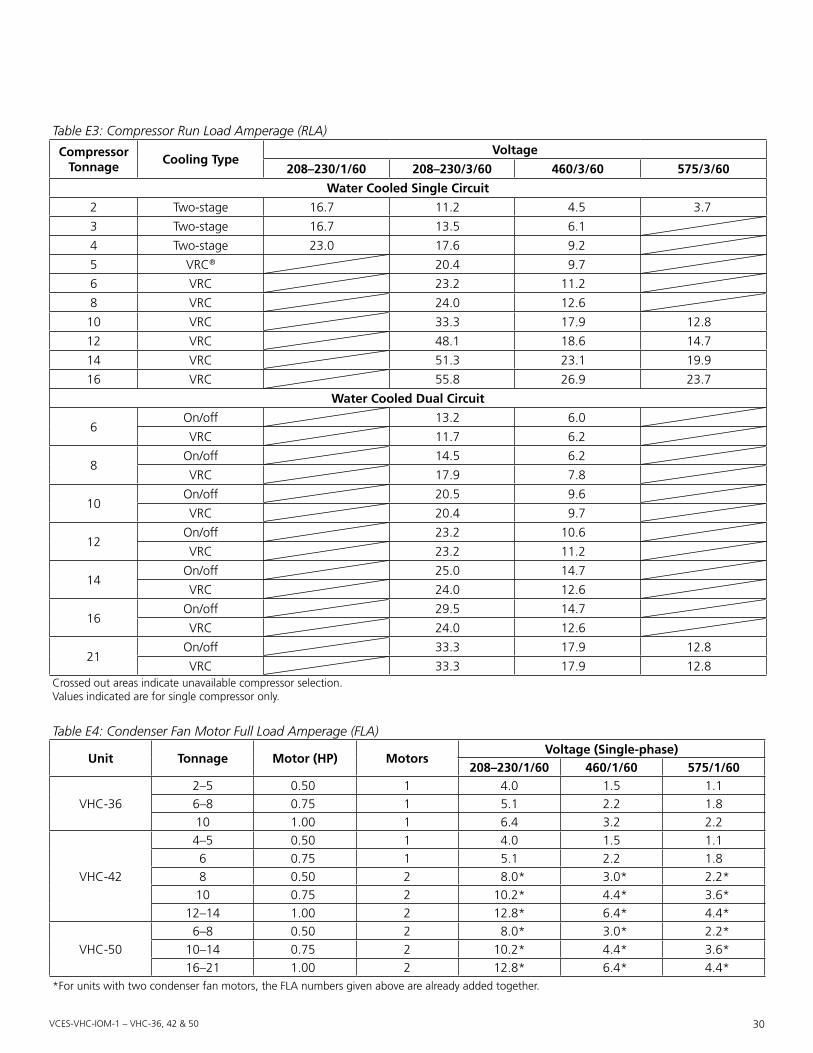
vces-vHc-iom-1 – vHc-36, 42 & 50 30
Table E4: Condenser Fan Motor Full Load Amperage (FLA)
unit tonnage Motor (Hp) MotorsVoltage (Single-phase)
208–230/1/60 460/1/60 575/1/60
VHC-362–5 0.50 1 4.0 1.5 1.16–8 0.75 1 5.1 2.2 1.810 1.00 1 6.4 3.2 2.2
VHC-42
4–5 0.50 1 4.0 1.5 1.16 0.75 1 5.1 2.2 1.88 0.50 2 8.0* 3.0* 2.2*10 0.75 2 10.2* 4.4* 3.6*
12–14 1.00 2 12.8* 6.4* 4.4*
VHC-506–8 0.50 2 8.0* 3.0* 2.2*
10–14 0.75 2 10.2* 4.4* 3.6*16–21 1.00 2 12.8* 6.4* 4.4*
*For units with two condenser fan motors, the FLA numbers given above are already added together.
Table E3: Compressor Run Load Amperage (RLA)
Compressor tonnage
Cooling typeVoltage
208–230/1/60 208–230/3/60 460/3/60 575/3/60
Water Cooled Single Circuit
2 Two-stage 16.7 11.2 4.5 3.7
3 Two-stage 16.7 13.5 6.1
4 Two-stage 23.0 17.6 9.2
5 VRC® 20.4 9.7
6 VRC 23.2 11.2
8 VRC 24.0 12.6
10 VRC 33.3 17.9 12.8
12 VRC 48.1 18.6 14.7
14 VRC 51.3 23.1 19.9
16 VRC 55.8 26.9 23.7
Water Cooled Dual Circuit
6On/off 13.2 6.0
VRC 11.7 6.2
8On/off 14.5 6.2
VRC 17.9 7.8
10On/off 20.5 9.6
VRC 20.4 9.7
12On/off 23.2 10.6
VRC 23.2 11.2
14On/off 25.0 14.7
VRC 24.0 12.6
16On/off 29.5 14.7
VRC 24.0 12.6
21On/off 33.3 17.9 12.8
VRC 33.3 17.9 12.8Crossed out areas indicate unavailable compressor selection.Values indicated are for single compressor only.

vces-vHc-iom-1 – vHc-36, 42 & 50 31
Maximum overcurrent protection (MCa) Calculation1.25 x FLA of larger hp motor or compressor = _____ 1.25 x heater FLA = + _____ Sum of all other motors FLA = + _____ Wheel drive motor and standard controls FLA = + _____ Indirect gas heater FLA = + _____ Calculated total MCA = _____
Minimum Current ampacity (Mop) Calculation1.25 x FLA of larger hp motor or compressor = _____ Electric heater FLA = + _____ Sum of all other motors FLA = + _____ Wheel drive motor and standard controls FLA = + _____ Indirect gas heater FLA = + _____ Calculated total MCA = _____ Actual MOP (from Table E6) = _____
Finding the actual Mop ValueFrom the calculated MOP value, select the next smallest value of protection from the Standard Overcurrent Protec-tion chart below to get the actual MOP value (maximum value of overcurrent device).
IMpoRtantIf this method leads to an actual MOP value being smaller than the calculated total MCA, then a larger value must rather be selected, such that the actual MOP is at least equal to the calculated total MCA.
Table E5: For Dual Circuit on/off units
6 tons Two 3 ton on/off compressors
8 tons Two 4 ton on/off compressors
10 tons Two 5 ton on/off compressors
12 tons Two 6 ton on/off compressors
14 tons Two 7 ton on/off compressors
16 tons Two 8 ton on/off compressors
21 tons Two 10 ton on/off compressors
For Dual Circuit VRC® units
6 tonsOne 3 ton on/off compressor One 3 ton VRC compressor
8 tonsOne 4 ton on/off compressor One 4 ton VRC compressor
10 tonsOne 5 ton on/off compressor One 5 ton VRC compressor
12 tonsOne 6 ton on/off compressor One 6 ton VRC compressor
14 tonsOne 7 ton on/off compressor One 7 ton VRC compressor
16 tonsOne 8 ton on/off compressor One 8 ton VRC compressor
21 tonsOne 10 ton on/off compressor One 10 ton VRC compressor
Table E6: Standard Overcurrent Protection3 40 250
4 45 300
5 50 350
6 60 400
7 70 450
8 80 500
9 90 600
10 100 650
12 110 700
15 125 750
20 150 800
25 175 850
30 200 900
35 225 1,000

vces-vHc-iom-1 – vHc-36, 42 & 50 32
occupied VentilationOccupied ventilation is achieved by closing the occupancy contact to the terminal interface shown in Figure F1. These terminals require a dry contact which could be provided by a number of types of controls such as a timer, light sensor, occupancy sensor, Building Management System or other. The unit will not operate unless these contacts are closed.
occupied timer SensorOccupied ventilation is achieved by connection to the ter-minal interface shown in Figure F2. These terminals require a dry contact which could be provided by a number of types of controls such as a timer, light sensor, occupancy sensor, Building Management System, or other. The unit will not operate unless these contacts are closed.
unoccupied RecirculationSupply fan recirculation for heating and cooling can be achieved by connecting dry contact controls to the termi-nal interface provided in the control panel area. This ter-minal requires a dry contact closure from a field provided and wired device.
Appendix F: Terminal Control Diagrams
301302304305305306307308320321322323324325374375376377
OCCUPANCYCONTACTCR
Note: This is the onlyconnection needed tostart single-speed units.
Figure F1: Occupied ventilation for DDC controls package and electro-mechanical controls (EMC)
301302304305305306307308320321322323324325326327328329
1 2 3 4 5
12
6
9
Figure F2: Occupied ventilation for DDC controls package and electro-mechanical controls (EMC)
301302304305305306307308320321322323324325326327328329
UNOCCUPIED RECIRCULATIONCONTACT (OPTIONAL)CR
Figure F3: Unoccupied recirculation for DDC controls units
IMpoRtantDDC units can be turned on/off through software.

vces-vHc-iom-1 – vHc-36, 42 & 50 33
VFD High Speed ControlHigh speed fan control can be achieved by connecting dry contact controls to the field wired (FW) terminals 374 and 375 for the supply fan and 376 and 377 for the exhaust fan. Only VFD units have the high speed option. These controls could also be the following: DPST switch, dehumidistat, CO2 sensor, light sensor, heat sensor, timer, Building Management System, etc.
Co2 Ventilation ControlVHCs can be directly controlled by a CO2 controller (acces-sory or field supplied) that can be connected to the supply and exhaust high speed contact terminals (VFD units only). As the CO2 levels exceed acceptable limits, dry contacts close raising high speed fan ventilation. See Figure F6. Alternatively a field supplied CO2 controller output can be connected to the BMS which can then be connected to the supply and exhaust fan modulating signal input ter-minals (VFD units only). As the CO2 levels rise and fall the BMS must modulate the signal to the supply and exhaust fans to change the ventilation rate proportionally. See Ap-pendix G. The minimum VFD speed is factory default set to 40 Hertz.
301302304305305306307308320321322323324325326327328329
UNOCCUPIEDRECIRCULATIONCONTACT (OPTIONAL)
CR
Figure F4: Unoccupied recirculation for electro-mechanical controls (EMC) units
301302304305305306307308320321322323324325374375376377
CR
CR
CR
OCCUPANCYCONTACT
SUPPLY BLOWER HIGH SPEED CONTACT
EXHAUST BLOWER HIGH SPEED CONTACT
Figure F5: VFD high speed control
301302304305305306307308320321322323324325374375376377
HIGH SPEEDCONTROL (SUPPLY BLOWER)
HIGH SPEEDCONTROL
RELAY CR1
OCCUPANCYCONTACTCRTB-1
TB-2
TB-1
TB-2
TB-3
TB-4
TB-5
RELAY CR1
RELAY CR1
HIGH SPEEDCONTROL (EXHAUST BLOWER)
3
5
4
6
Figure F6: CO2 ventilation control
IMpoRtantRemoval of dry contacts that close on high speed termi-nals is required for VFDs to modulate.

vces-vHc-iom-1 – vHc-36, 42 & 50 34
Smoke DetectorLocate in a normally occupied area of premises. Recom-mended for compliance to NFPA-90A and IMC Code 606.
VHCs can be equipped with a duct mount smoke detector which will monitor the air when passing through the duct system into the VHC. When sufficient smoke is detected, an alarm condition is activated. By connecting the occu-pied timer/sensor contacts to the NC alarm auxiliary con-tacts on the duct sensor, an alarm condition will open the auxiliary contact and stop operation of the VHC.
Dirty Filter SensorThe VHCs can be equipped with dirty filter sensors which monitor the pressure across the filters and close the con-tacts when the filters become restricted with dirt. Field wired connections can be made to the terminal interface for both the supply and exhaust filter sensors.
301302410411
24V 24V NC C
1 2 15 16
Figure F7: Smoke detector
301302304305305306307308320321322323324325326327328329
DIRTY SUPPLY FILTER24 VAC+ OUTPUTS20 VA MAXIMUM DIRTY EXHAUST FILTER
Figure F8: Dirty filter control
IMpoRtantOn DDC units, there is no dirty filter sensor output to connect to. Rather, the dirty filter sensor is connected to the DDC controller and will display a dirty filter alarm on the BacStat II (user interface) when it senses the filter is dirty.
IMpoRtantThis wiring configuration cannot be used on DDC units that are scheduled on/off through software.

vces-vHc-iom-1 – vHc-36, 42 & 50 35
Control Field Wiring (FW)Low voltage terminal control consists of the following:
Electro-mechanical.Controls.(EMC).UnitInputs• Occupied ventilation timer/sensor
– Dry contact• Occupied recirculation (if equipped)
– Dry contact• Unoccupied recirculation (if equipped)
– Dry contact• Unit fault
– Dry contact• Cooling stage 1 (if equipped)
– Dry contact• Cooling stage 2 (if equipped)
– Dry contact• Heat enable (if equipped)
– Dry contact• Modulating heat (if equipped)
– 0 to 10 VDC• Reheat valve on/off 1 (if equipped)
– Dry contact• Reheat valve on/off 2 (if equipped)
– Dry contact• Reheat valve modulating (if equipped)
– 0 to 10 VDC• Modulating supply motor speed (if equipped)
– 0 to 10 VDC• Modulating exhaust motor speed (if equipped)
– 0 to 10 VDCoutputs• Supply fan on• Exhaust fan on• External unit fault• Defrost on (if equipped with recirculation or exhaust
only defrost options)• Free cooling on (if equipped with free cooling option)• Wheel failure (if equipped with wheel rotation sensor
option)• Dirty supply filters (if equipped with dirty filter sensor
option)• Dirty exhaust filters (if equipped with dirty filter sen-
sor option)• Cooling on (if equipped with cooling)• Heating on (if equipped with gas heat)
Appendix G: Standard Field Wiring (FW) Terminals
IMpoRtantAll output controls are 24 VAC unless otherwise indicated.
24 VAC−
24 VAC+
SCR ELECTRIC POSTHEAT (0–10 VDC+) (OPTIONAL)
SCR ELECTRIC POSTHEAT (0–10 VDC−) (OPTIONAL)
SCR ELECTRIC POSTHEAT (SHIELD) (OPTIONAL)
FREE COOLING ON (OPTIONAL)
DIRTY SUPPLY FILTER (OPTIONAL)
DIRTY EXHAUST FILTER (OPTIONAL)
WHEEL FAILURE (OPTIONAL)
EXHAUST BLOWER ON
COIL LOW LIMIT (OPTIONAL)
24 VAC+OUTPUTS
20 VA MAXIMUM
SUPPLY BLOWER ON
HEATING (ON) (OPTIONAL)
COOLING STAGE 1 (ON) (OPTIONAL)
HOT GAS REHEAT MODULATING (0–10 VDC+) (OPTIONAL)
HOT GAS REHEAT MODULATING (0–10 VDC−) (OPTIONAL)
GAS HEAT MODULATING (0–10 VDC+) (OPTIONAL)
GAS HEAT MODULATING (0–10 VDC−) (OPTIONAL)
COOLING STAGE 2 (ON) (OPTIONAL)
SUPPLY BLOWER MODULATING (SHIELD) (OPTIONAL)
SUPPLY BLOWER MODULATING (0–10 VDC−) (OPTIONAL)
SUPPLY BLOWER MODULATING (0–10 VDC+) (OPTIONAL)
EXHAUST BLOWER MODULATING (0–10 VDC+) (OPTIONAL)
EXHAUST BLOWER MODULATING (0–10 VDC−) (OPTIONAL)
EXHAUST BLOWER MODULATING (SHIELD) (OPTIONAL)
COMPRESSOR ONE STATUS (OPTIONAL)
COMPRESSOR TWO STATUS (OPTIONAL)
CR
CR
CR
CR
CR
CR
CR
CR
CR
CR
CR
CR
CR
CR
CR
CR
UNOCCUPIED RECIRCULATIONCONTACT (OPTIONAL)
OCCUPANCYCONTACT
COOLING STAGE 2CONTACT (OPTIONAL)
GAS HEAT ENABLECONTACT (OPTIONAL)
REHEAT VALVE 2CONTACT (OPTIONAL)
REHEAT VALVE 1CONTACT (OPTIONAL)
SCR ELECTRIC HEAT ENABLECONTACT (OPTIONAL)
GAS HEAT STAGE 2(OPTIONAL)
ELECTRIC HEAT STAGE 1CONTACT (OPTIONAL)
ELECTRIC HEAT STAGE 2CONTACT (OPTIONAL)
ELECTRIC HEAT STAGE 3CONTACT (OPTIONAL)
ELECTRIC HEAT STAGE 4CONTACT (OPTIONAL)
COOLING STAGE 1CONTACT (OPTIONAL)
SUPPLY BLOWER HIGH SPEEDCONTACT (OPTIONAL)
EXHAUST BLOWER HIGH SPEEDCONTACT (OPTIONAL)
UNIT FAULT
371
363
370
310311312313
309308
302301
304A
305306307
314315320321
304305
326325324322
329
354
360359
361362
368364
358357
355
352353
356
376375
377410
502
411501
503502-S
504504-S
374
372373
Figure G1: Electro-mechanical controls (EMC)

vces-vHc-iom-1 – vHc-36, 42 & 50 36
DDC.Controls.UnitInputs• Occupied ventilation
– Dry contact• Unoccupied recirculation (if equipped)
– Dry contact• Occupied recirculation (if equipped)
– Dry contact• Unit fault
– Dry contact• Cooling override (if equipped)
– Dry contact• Dehumidification (if equipped)
– Dry contact• Heating override (if equipped)
– Dry contact• Supply blower high speed (if equipped)
– Dry contact• Exhaust blower high speed (if equipped)
– Dry contact• Modulating supply motor speed (if equipped)
– 0 to 10 VDC• Modulating exhaust motor speed (if equipped)
– 0 to 10 VDCoutputs
• Chilled water valve (field supplied) – 0 to 10 VDC (direct acting)
• Hot water valve (field supplied) – 0 to 10 VDC (direct acting)
• Remote condenser compressor section – stage one (field supplied) – Dry contact
• Remove condenser compressor section – stage two (field supplied) – Dry contact
• WSHP two-way water shut-off valve with on/off ac-tuator (accessory or field supplied) – 24 VAC terminals
Please note that the location of the field wiring (FW) ter-minal and panel (PNL) terminal may vary depending upon options selected. See Figure G3for the two different loca-tions within the electrical panel.
IMpoRtantTerminal contacts are provided to open/close/modulate the type of heating or cooling valves, contacts, etc. as required, which are external to the unit and supplied by others or available as shipped loose accessories for con-nection to internal coils selected.
24 VAC−
24 VAC+
SUPPLY BLOWER MODULATING (SHIELD) (OPTIONAL)
EXHAUST BLOWER MODULATING (0–10 VDC+) (OPTIONAL)
SUPPLY BLOWER MODULATING (0–10 VDC−) (OPTIONAL)
SUPPLY BLOWER MODULATING (0–10 VDC+) (OPTIONAL)
DRY CONTACT OUTPUTS12A/125 VAC10A/250 VAC
MOTORIZED WATER VALVE COM (24 VAC COM)
MOTORIZED WATER VALVE CLOSE (24 VAC)
MOTORIZED WATER VALVE OPEN (24 VAC)
EXHAUST BLOWER MODULATING (0–10 VDC−) (OPTIONAL)
EXHAUST BLOWER MODULATING (SHIELD) (OPTIONAL)
HOT WATER VALVE ACTUATOR (0–10 VDC−) (OPTIONAL)
HOT WATER VALVE ACTUATOR (0–10 VDC+) (OPTIONAL)
CHILLED WATER VALVE ACTUATOR (0–10 VDC−) (OPTIONAL)
CHILLED WATER VALVE ACTUATOR (0–10 VDC+) (OPTIONAL)
BACSTAT NET+
BACSTAT NET−
BACSTATII 24 VAC COM
BACSTATII 24 VAC+
OUTPUTS FOR BACSTATIIDC3036
0–10 VDC OUTPUTS20 mA MAX
CR
CR
CR
CR
CR
CR
CR
CR
CR
CR
CR
CR
UNOCCUPIED RECIRCULATIONCONTACT (OPTIONAL)
OCCUPANCYCONTACT
OCCUPIED RECIRCULATIONCONTACT (OPTIONAL)
HEATING OVERRIDECONTACT (OPTIONAL)
LOW LIMITCONTACT
COOLING OVERRIDECONTACT (OPTIONAL)
DEHUMIDIFICATIONCONTACT (OPTIONAL)
EXHAUST BLOWER HIGH SPEEDCONTACT (OPTIONAL)
UNIT FAULTCONTACT
SUPPLY BLOWER HIGH SPEEDCONTACT (OPTIONAL)
CONDENSER SECTION STAGE 2OUTPUT CONTACT (OPTIONAL)
CONDENSER SECTION STAGE 1OUTPUT CONTACT (OPTIONAL)
316317318319
315314
302301
304
306306307
370371
363364
372373
305305
377376375374
380381
400
382383
402401
403
501
503
502
410411
502-S
435436437
504-S504
Figure G2: DDC controls
PNL
FW
PNL
FW
Figure G3: Terminal locations

vces-vHc-iom-1 – vHc-36, 42 & 50 37
Table H1: VHC-36 Temperature Rise Over Gas Furnace (°F) – 4:1, 2:1 and On/off Modelsair Volume (CFM) 100 MBH 125 MBH 200 MBH
800 94.1900 83.6
1,000 75.2 94.11,100 68.4 85.51,200 62.7 78.41,300 57.9 72.31,400 53.7 67.21,500 50.2 62.7 100.31,600 47.0 58.8 94.11,700 44.3 55.3 88.51,800 41.8 52.3 83.61,900 39.6 49.5 79.22,000 37.6 47.0 75.22,100 35.8 44.8 71.72,200 34.2 42.8 68.42,300 32.7 40.9 65.42,400 31.4 39.2 62.72,500 30.1 37.6 60.2
Use caution in shaded areas.Values above are calculated at sea level.Temperature rise = Sea level temperature rise / (1−Elevation (ft) x 0.0000334)Gas inlet pressure required for natural gas minimum 5” w.c., maximum 13.5” w.c.; for propane minimum 11” w.c., maximum 13.5” w.c.High altitude kit required for elevations over 2,000 feet.
Table H2: VHC-42 Temperature Rise Over Gas Furnace (°F) – 4:1, 2:1 and On/off Modelsair Volume (CFM) 200 MBH 250 MBH 300 MBH 350 MBH
1,5001,600 94.11,700 88.51,800 83.61,900 79.22,000 75.2 94.12,100 71.7 89.62,200 68.4 85.52,300 65.4 81.82,400 62.7 78.4 94.12,500 60.2 75.2 90.32,600 57.9 72.3 86.82,700 55.7 69.7 83.62,800 53.7 67.2 80.6 94.12,900 51.9 64.9 77.8 90.83,000 50.2 62.7 75.2 87.83,100 48.5 60.7 72.8 84.93,200 47.0 58.8 70.5 82.33,300 45.6 57.0 68.4 79.83,400 44.3 55.3 68.4 77.53,500 43.0 53.7 64.5 75.2
Use caution in shaded areas.Values above are calculated at sea level.Temperature rise = Sea level temperature rise / (1−Elevation (ft) x 0.0000334)Gas inlet pressure required for natural gas minimum 5” w.c., maximum 13.5” w.c.; for propane minimum 11” w.c., maximum 13.5” w.c.High altitude kit required for elevations over 2,000 feet.
Appendix H: Temperature Rise Over Gas Furnace

vces-vHc-iom-1 – vHc-36, 42 & 50 38
Table H3: VHC-50 Temperature Rise Over Gas Furnace (°F) – 4:1, 2:1 and On/off Modelsair Volume (CFM) 250 MBH 300 MBH 350 MBH 400 MBH
2,500 75.2 90.32,600 72.3 86.82,700 69.7 83.62,800 67.2 80.6 94.12,900 64.9 77.8 90.83,000 62.7 75.2 87.83,100 60.7 72.8 84.93,200 58.8 70.5 82.3 94.13,300 57.0 68.4 79.8 91.23,400 55.3 66.4 77.5 88.53,500 53.7 64.5 75.2 86.03,600 52.3 62.7 73.2 83.63,700 50.8 61.0 71.2 81.33,800 49.5 59.4 69.3 79.23,900 48.2 57.9 67.5 77.24,000 47.0 56.4 65.8 75.24,100 45.9 55.1 64.2 73.44,200 44.8 53.7 62.7 71.74,300 43.7 52.5 61.2 70.04,400 42.8 51.3 59.9 68.44,500 41.8 50.2 58.5 66.94,600 40.9 49.1 57.2 65.44,700 40.0 48.0 56.0 64.04,800 39.2 47.0 54.9 62.74,900 38.4 46.1 53.7 61.45,000 37.6 45.1 52.7 60.25,100 36.9 44.3 51.6 59.05,200 36.2 43.4 50.6 57.95,300 35.5 42.6 49.7 56.85,400 34.8 41.8 48.8 55.75,500 34.2 41.0 47.9 54.7
Use caution in shaded areas.Values above are calculated at sea level.Temperature rise = Sea level temperature rise / (1−Elevation (ft) x 0.0000334)Gas inlet pressure required for natural gas minimum 5” w.c., maximum 13.5” w.c.; for propane minimum 11” w.c., maximum 13.5” w.c.High altitude kit required for elevations over 2,000 feet.

vces-vHc-iom-1 – vHc-36, 42 & 50 39
The furnace module covered by this appendix is a com-ponent of a “Listed” product, subject to the guidelines of application as designated by the Certifying Agency and outlined in the appliance Manufacturer’s installation and operation instructions.
The information provided in this appendix applies to the furnace module, installed in the appliance and to its op-eration, maintenance and service. Refer to the appliance Manufacturer’s instructions for information related to all other components.
Inspection on arrival1. Inspect unit upon arrival in accordance with unit
Manufacturer’s instructions and follow their recom-mendations if any damage has occurred.
2. Prior to installation locate Manufacturer’s rating plate and verify that furnace is equipped for the available fuel supply and power supply at point of installation.
unit Location/Clearances1. Be sure that the unit is located with respect to build-
ing construction and other equipment to provide ready access and clearance to access panels or doors that must be opened to permit adjustment and ser-vicing of the heating section.
2. The heating unit provided is listed for installation on the positive side of the circulating air blower only.
3. The furnace module in this unit must be installed in a non-combustibile duct or cabinet and is not designed to have any portion of the heat exchanger exposed outside the duct or cabinet in which it is housed.
4. Do not install unit where it may be exposed to po-tentially explosive or flammable vapors or combus-tible dust.
5. Do not locate unit in areas where corrosive vapors (such as chlorinated, halogenated or acidic or air-borne substances containing silicone) are present in the atmosphere or can be mixed with combustion air entering heater.
Venting and Combustion air SupplyOutdoor.InstallationThe heating module is power vented with a combustion air draft inducer/blower and needs an ample supply of air for proper and safe combustion of the fuel gas. Do not block or obstruct air openings to the area where the heating unit is installed. Combustion air openings in the cabinet should be sized to provide 1 sq. in. of free area per 4,000 Btuh of input. Combustion air inlet and flue gas outlet must be located in the same pressure zone to minimize effects of wind on burner and heater perfor-mance. Provide at least 6 feet clearance to side of the unit, where the combustion air inlet or vent (flue) gas discharge is located, from walls, parapets or adjacent buildings or equipment. Do not locate unit near building ventilators or exhausts, or areas where corrosive chemical vapors can be drawn into combustion air supply.
The venting system is designed for direct discharge of flue gases to the outdoors. The vent discharge opening should be located to provide an unobstructed discharge to the outside and should be located as far from the combus-tion air inlet as possible but must always be located in the same pressure zone as the combustion air inlet. Vent duct should pitch down toward outlet, to ensure that any condensate that occurs in vent duct drains away from combustion blower fan housing. The duct opening should be protected by a ½” x ½” [12 x 12 mm] mesh screen. An optional rain hood may be used over the discharge open-ing to prevent wind driven rain from entering the vent duct, but should not intersect the flue gas discharge path. See Figure I1.
Appendix I: In-shot Gas Burner Information for 2:1, 4:1 and On/Off
! WaRnIngImproper installation, adjustment, alteration, service or maintenance can cause injury or death. Read the installa-tion, operation and maintenance instructions in this appen-dix thoroughly before installing or servicing this equipment.
WaRnIng – FoR YouR SaFEtYWhat to do if you smell gas:
1. Do not touch electrical switches or use any phone in the building.
2. Extinguish any open flame.3. Leave the building immediately.4. Immediately call gas supplier.
!
IMpoRtantThe use of this appendix is specifically intended for a qualified installation and service agency. A qualified instal-lation and service agency must perform all installation and service of these appliances.
IMpoRtantCombustion air intake and vent locations differ; see submittal drawings for actual locations. Vent termina-tion must comply with the National Fuel Gas Code 223.1 (NFPA54) in the U.S., in Canada to the Gas Installation Code Can/CGA B149.

vces-vHc-iom-1 – vHc-36, 42 & 50 40
Outdoor units must be individually vented, unless provided with a special vent system by the Manufacturer.
Where sufficient clearance for proper horizontal venting cannot be provided, or in jurisdictions requiring a 4 foot separation between flue gas discharge and combustion air inlet, flue gases need to be vented vertically. Refer to Fig-ure I2 and Figure I3 for suitable venting methods.
Vent pipe must terminate at least 1 foot above the cabi-net. The vent must be located on the same side of the appliance as the combustion air inlet opening. Condensa-tion in the vent pipe is likely during heater start-up cycle and provision for drainage must be provided when a 90° elbow is employed in the vent piping. The open venting system shown will permit condensate to drain from the “T” fitting.
Do not locate unit near building ventilators or exhausts, or areas where corrosive chemical vapors can be drawn into combustion air supply.
Do not install units in locations where flue products can be drawn in the adjacent building openings such as windows, fresh air intakes, etc.
Indoor.InstallationLocate heating unit to ensure an adequate supply of fresh air to replace air used in the combustion and ventilation process. The heating unit must be installed in a location with adequate clearances to provide for an adequate com-bustion air space, service and inspection and proper clear-ances from combustible construction. The heating unit shall be located in such a manner that it does not interfere with the circulation of air in the heated space.
All fuel burning equipment must be supplied with air that enters into the combustion process and is then vented outdoors. Sufficient air must enter the appliance location to replace the air exhausted through the vent system. Do not install appliance in a confined space without providing wall openings to and from this space. If building construc-tion is such that the normal infiltration does not provide sufficient air for combustion and venting, outside air must be introduced. Install air openings that provide a total free area in accordance with the National Fuel Gas Code Z223.1 (NFPA 54) in the US. In Canada, refer to Can/CGA-B149 Installation Code.
All duct furnace modules must be connected to a venting system to convey flue gases outside of the heated space. Refer to installation codes noted above for specific require-ments for the product type being installed.
For multiple unit installations, each heater requires an in-dividual vent pipe and termination, unless the equipment Manufacturer provides an approved special vent system with the heating unit.
Vertically Vented Furnaces (see Figure I4) – Category I (per nFgC and anSI Z21.13 is non-positive vent pressure and non-condensing)1. Use single wall or double wall (Type B) vent pipe di-
ameters for the appropriate models.2. Maximize the height of the vertical run of vent pipe.
A minimum of 5 feet [1.5 m] of vertical pipe is re-quired. The top of the vent pipe must extend at least 2 feet [0.61 m] above the highest point on the roof. Use Listed Type B vent for external runs. An approved weatherproof vent cap must be installed to the vent termination.
3. Horizontal runs must not exceed 75% of the vertical height of the vent pipe, up to a maximum of 10 feet [3 m]. Horizontal runs should be pitched upward ¼
Rain hood(optional)
Mesh screen
AHU cabinet
Rain hood(optional)
Flue gas flowunobstructed
Combustion airinlet cover
Combustionair opening
Combblwr.
AHU cabinet
Meshscreen
Figure I1: Outdoor horizontal venting
Rain cap maybe used, if required
1 ft min.
Support bracket
4 ft min.18.0” min.
12” min.
“T” open toatmosphere
Combustionair inlet
Combustionblower
Figure I2: Outdoor vertical venting
Must use anapprovedvent cap fortermination
Side View
1 ft min.
18” min.
4 ft min.
5” diameter min.6” diameter max.
Drill ¼” hole forcondensate drainage
Figure I3: Outdoor vertical venting – side view

vces-vHc-iom-1 – vHc-36, 42 & 50 41
inch per foot [21 mm/m] and should be supported at 3 foot [1 m] maximum intervals.
4. Design vent pipe runs to minimize the use of elbows. Each 90° elbow is equivalent to 5 feet [1.5 m] of straight vent pipe run.
5. Vent pipe should not be run through unheated spaces. If such runs cannot be avoided, insulate vent pipe to prevent condensation inside vent pipe. Insula-tion should be a minimum of ½” [12.7 mm] thick, foil faced material suitable for temperatures up to 500°F.
6. Dampers must not be used in vent piping runs. Spill-age of flue gases into the occupied space could result.
7. Vent connectors serving Category I heaters must not be connected into any portion of a mechanical draft system operating under positive pressure.
Horizontally Vented Furnaces (see Figure I5) – Category III (per nFgC and anSI Z21.13 is positive vent pressure and non-condensing)Pressures in Category III venting systems are positive and therefore, care must be taken to avoid flue products from entering the heated space. Use only vent materials and components that are UL listed and approved for Category III venting systems.
All vent pipe joints must be sealed to prevent leakage into the heated space. Follow instruction provided with approved venting materials used. The proper vent pipe diameter must be used, to ensure proper venting of com-bustion products, as follows:
• Input ratings of 150,000 Btuh [43,960 W] to 400,000 Btuh [117,228 W] – 6” diameter [152 mm]
• Input ratings of 75,000 Btuh [21,980 W] to 149,999 Btuh [43,958 W] – 5” diameter [126 mm]
The total equivalent length of vent pipe must not exceed 25 feet [7.62 m]. Equivalent length is the total length of straight sections, plus 5 feet [1.52 m] for each 90° elbow and 2.5 feet [0.76 m] for each 45° elbow.
The vent system must also be installed to prevent collec-tion of condensate. Pitch horizontal pipe runs downward ¼ inch per foot [21 mm/m] toward the outlet to permit condensate drainage. Insulate vent pipe exposed to cold air or routed through unheated areas. Insulate vent pipe runs longer than 10 feet [3 m]. Insulation should be a min-imum of ½” [12 mm] thick foil faced material suitable for temperatures up to 500°F. Maintain 6” [152 mm] clear-ance between vent pipe and combustible materials.
A vent cap approved for horizontal venting must be provided. Vent cap inlet diameter must be same as the required vent pipe diameter. The vent terminal must be at least 12” [305 mm] from the exterior wall that it passes through to prevent degradation of building material by flue gases. The vent terminal must be located at least 1 foot [305 mm] above grade, or in snow areas, at least 3 feet [1 m] above snow line to prevent blockage. Addition-ally, the vent terminal must be installed with a minimum horizontal clearance of 4 feet [1.2 m] from electric meters, gas meters, regulators or relief equipment. Periodically clean the screens in the vent terminal (where applicable).
Each appliance must have its own individual vent pipe and terminal. Do not connect vent system from horizontally vented units to other vent systems or a chimney.
Through the wall vents shall not terminate over public walkways, or over an area where condensate or vapor could create a nuisance or hazard.
Exh
aust
Roof lineExhaust vent
terminal
B
A
Air inlet
A = 12” minimumB = 12” minimum, but should size according to expected snow depth
Figure I4: Indoor vertical venting
A = 12” minimum
Exterior wall
A
Exhaust
Air inlet
Exhaust vent terminal
Pitch vent pipedownward fromfurnace ¼ inch
per foot
Figure I5: Indoor horizontal venting

vces-vHc-iom-1 – vHc-36, 42 & 50 42
Separated Combustion air Intake SystemsOn indoor units for operation with separated combustion air intake systems, the burner section is in a reasonably air-tight vestibule compartment, as these systems provide combustion air from outside the heated space and vent the products of combustion outdoors. No air openings are to be made in the vestibule to maintain a reasonably air-tight seal. Additionally the unit must include the following:
1. A suitable air-tight gasket on the vestibule door or access panel.
2. An observation window in the door to permit ob-servation of ignition and main burner flame during operation and servicing.
3. A door or panel interlock switch to ensure that door or panel is closed or in place during operation.
4. Openings into the vestibule space for attachment of inlet air supply pipe and vent pipe, sized for the Bthu [W] input rating.
Proper installation of combustion air intake and flue gas exhaust piping are essential to proper operation of the in-shot gas burner module. Inlet air pipe must be the same size as vent pipe based on input ratings. See Figure I6 and Figure I7 for recommended installation.
gas Supply, piping and Connections1. Installation of piping must conform with local build-
ing codes and ordinances, or in the absence of local codes with ANSI Z223.1 the National Fuel Gas Code. In Canada, installation must be in accordance with CAN/CGA-B149.1 for natural gas and B149.2 for propane units.
2. Gas piping must be sized for the total Btu input of all units (heaters) serviced by a single supply. Refer to unit Manufacturer’s instructions for proper sizing. Each furnace has a ¾” NPT piping connection lo-cated on the exterior of the cabinet.
3. Be sure that gas regulators servicing more than one heater have the proper pipe and internal orifice size for the total input of all heaters serviced by the regulator.
4. Minimum inlet gas pressure required for natural gas operation is 5.0” w.c. and for propane (LP) gas is 11.0” w.c. Maximum inlet pressure for either gas is 13.5” w.c., with the furnace operating. For higher gas pressures, a separate field supplied and installed high pressure regulator with full internal relief is re-quired to reduce pressure to within minimum and maximum range.
5. A 1/8” NPT tap is provided on the inlet side of the gas valve to the heater. A fitting suitable for connec-tion to a pressure gauge capable of measuring gas pressure should be connected to each heater serviced by a single regulator so that gas pressure at each heater can be measured with all heaters in operation (see Figure I8).
6 ft. [1.8 m] min.to wall or
adjoining building
Exhaust vent
Approved vent caps
Combustion air inlet
18” [0.46 m] min. * (See note)
Tee with drip leg andcleanout cap
18” [0.46 m] min.
* Provides sufficient height toexceed expected snow depth
Heating appliance
Exhaust
12” [0.3 m] min.
2.5 ft. [0.75 m] min.
Figure I6: Separated combustion – vertical venting
18” [0.46 m]min. @ CL
5 ft. [1.5 m] min.25 ft. [15.2 m] max.equivalent length
Pitch pipes down ¼ in./ft [21 mm/m]toward terminal caps to allow forcondensate drainage
12” [0.3 m]
3 ft. [0.9 m] min.
Building overhang
6 ft. [1.8 m]min. Adjacent
building
3 ft. [0.9 m] min.above gradesize by expectedsnow depth
24”[0.6 m]
Note: Be sure that the vent cap used for horizontal venting applications is approved for horizontal application. Certain Manufacturer’s vent terminals are approved for vertical installation only.
Figure I7: Separated combustion – horizontal venting
Max. 13.5” w.c.
Pressureregulator
Gassupply
Unit 1 Unit 2 Unit 3
Min. 5.0” w.c. natural gasMin. 11.0” w.c. propane gas
Figure I8: Gas piping line, regulator and overpressure relief valve must be sized to be within the minimum and maxi-mum pressure ratings of all furnaces or appliances serviced.
IMpoRtantApproved combustion supply air intake and exhaust flue gas vent piping and terminals must be used between the unit and outdoors for combustion supply air and exhaust flue gas. The inlet and outlet terminals must be located in the same outdoor pressure zone to provide for safe appli-ance operation.

vces-vHc-iom-1 – vHc-36, 42 & 50 43
6. A drip leg (sediment trap) and a manual shut-off valve must be provided immediately upstream of the gas control on the heating unit. To facilitate servicing of unit, installation of a union is recommended (see Figure I9). The appliance must be isolated from the gas supply system by closing its individual manual shut-off valve during any pressure testing of the gas supply piping system at test pressures greater than 13.5” w.c. [½ psi]. Always use clean, scale-free pipe and malleable iron fittings, and remove all cutting and threading debris prior to connecting pipes. Firmly support the gas piping so that it cannot be dislodged from its installed position.
Gas supply line
Manual gasshut-off valve
Ground joint unionwith brass seat
To controls
Plugged 1/8” NPT testgauge connection
Sediment trap
3”min.
Gas supply line
1
Figure I9: Union installation
WaRnIng1. All field gas piping must be pressure/leak tested
prior to operation. Never use an open flame to check for leaks. Use a soap solution or other leak detecting solution for testing.
2. Gas pressure to appliance controls must never ex-ceed 13.5” w.c. [½ psi].
!
WaRnIng1. When pressure testing at ½ psi or less, close the man-
ual shut-off valve on the appliance before testing. 2. When pressure testing gas supply line at ½ psi
or higher, close manual gas valve and disconnect heater from supply line to be tested. Cap or plug the supply line.
Figure I10: Vertical airflow configuration

vces-vHc-iom-1 – vHc-36, 42 & 50 44
1. Airflow may be either upflow or downflow for heater as shown, without any difference in system performance.
2. In this configuration, condensate due to operation of air conditioning system would drain through the open heat exchanger tubes near base of heater. A conden-sate drain pan should be provided for these applica-tions, if none is incorporated integral to the unit.
3. Some condensation may occur in the flue collector box and it is recommended that a drain tube be con-nected to the lower condensate drain fitting as well.
gas Input RateThe correct heat capacity of the furnace is controlled by the burner orifices and the gas manifold pressure. The manifold pressure is factory set but should be checked at the time of start-up as described below.
operating and Safety Instructions1. This furnace module does not have a pilot. It is
equipped with a direct spark ignition device that au-tomatically lights the gas burner. Do not try to light burners by hand.
2. Before operating, leak test all gas piping up to heater gas valve. Smell around the unit area for gas. Do not attempt to place heater in operation until source of gas leak is identified and corrected.
3. Use only hand force to push and turn the gas control knob to the ‘On’ position. Never use tools. If knob does not operate by hand, replace gas valve prior to starting the unit. Forcing or attempting to repair the gas valve may result in fire or explosion.
4. Do not attempt to operate unit if there is indication that any part or control has been under water. Any control or component that has been under water must be replaced prior to trying to start the unit.
Start-up1. Turn thermostat or temperature controller to its low-
est setting.2. Turn off gas supply at the manual shut-off valve.3. Turn off power to the unit at the disconnect switch.4. Remove access panel or open door to unit vestibule
housing the gas heater.5. Move gas control knob to ‘Off’ position. The furnace
module is provided with a supply air proving interlock switch to ensure minimum supply airflow prior to burner operation. Set the switch after ductwork has been completed to open just below the minimum supply airflow on the furnace rating plate.
6. Install a tapped fitting for attachment to a manom-eter (or other gauge suitable for 14.0” w.c.) in the inlet pressure tap and for 10.0” w.c. in the manifold pressure tap.
7. Wait five minutes for any gas to clear out. If you smell gas, see Step 2 above and correct leak. If you do not smell gas or have corrected any leaks, go to the next step.
8. Turn gas control knob to ‘On’ position.9. Open all manual gas valves.10. Turn power on at disconnect switch.11. Set thermostat or controller to its highest position to
initiate call for heat and maintain operation of unit.12. Draft inducer will run for a 15 to 30 second prepurge
period. See Sequence of Operation provided.13. At the end of the pre-purge, the direct spark will be
energized and gas valve will open.14. Burners ignite.
Check.and.Adjust.Manifold.Pressure• For two-stage (TS) and modulating control (MD)
systems manifold pressure should be 1.2” w.c. for natural gas and 2.7” w.c. for propane during the 90 second warm-up period. Adjust low regulator on two-stage gas valve, if necessary. After 90 seconds, manifold pressure should increase to 3.5” w.c. for natural gas and 10.0” w.c. for propane within 30 to 45 seconds for two-stage units. For modulating units, the manifold pressure will vary depending on the analog input signal. At 10 VDC, pressure should be 3.5” w.c. for natural gas and 10.0” w.c. for propane; at 0 volts the manifold pressure should be 0.4” w.c. for natural gas and 1.1” w.c. for propane.
Figure I11: Gas valve
WaRnIng – FoR YouR SaFEtYThe use and storage of gasoline or other flammable va-pors and liquids in open containers in the vicinity of this appliance is hazardous.
!
IMpoRtantIf modulating controls are provided on furnace module, a separate setup sheet is included with this manual. Refer to that setup sheet for complete start-up instruc-tions. The installation is to be adjusted to achieve the air throughput within the range specified on the gas heater rating plate.

vces-vHc-iom-1 – vHc-36, 42 & 50 45
• For on/off units, the manifold pressure should be 3.5” w.c.
Failure.to.Ignite1. On the initial start-up, or after unit has been off long
periods of time, the first ignition trial may be unsuccess-ful due to need to purge air from manifold at start-up.
2. If ignition does not occur on the first trial, the gas and spark are shut off by the ignition control and the control enters an inter-purge period of 15 seconds, during which the draft inducer continues to run.
3. At the end of the inter-purge period, another trial for ignition will be initiated.
4. Control will initiate up to three ignition trials on a call for heat before lockout of control occurs.
5. Control can be brought out of lockout by turning thermostat or controller to its lowest position and waiting five seconds and then turning back up to call for heat. Controls provided will automatically reset after one hour and initiate a call for heat.
Burner FlamesPrior to completing the start-up, check the appearance of the main burner flame. See Figure I12 and Figure I13 for flame characteristics of properly adjusted natural gas systems.
1. The burner flame should be predominately blue in color, well defined and centered at the tube entry. Distorted flame, yellow tipping of natural gas flame or a long yellow flame on propane, may be caused by lint and dirt accumulation inside burner or at burner ports, at air inlet between burner and mani-fold pipe, or debris in the main burner orifice. Soft brush or vacuum clean affected areas.
2. Poorly defined, substantially yellow flames or flames that appear lazy, indicate poor air supply to burners or excessive burner input. Verify gas supply type and manifold pressure with rating plate.
3. Poor air supply can be caused by obstructions or blockage in heat exchanger tubes or vent discharge pipe. Inspect and clean as necessary to eliminate blockage. Vacuum any dirt or loose debris. Clean heat exchanger tubes with stiff brush. Poor flame characteristics can also be caused by undersized combustion air openings or flue gas recirculation into combustion air supply. Increase air opening size or re-direct flue products to prevent recirculation.
4. Reduced air delivery can also be the result of fan blade slippage, dirt accumulation in the fan blade or low voltage to draft inducer motor. Inspect draft fan assembly and be sure fan blade is secure to motor shaft. Check line voltage to heater.
Shut Down1. Set thermostat or controller to lowest setting.2. Turn off electrical supply to unit at disconnect switch.3. Turn off manual gas supply.4. Disconnect manifold and inlet pressure taps and re-
install pipe plugs.5. Replace vestibule access panel or close door.
normal operation1. Turn on electrical supply to unit at disconnect switch.2. Turn on manual gas supply.3. Set thermostat or temperature controller to desired
temperature.4. Information outlining the normal Sequence of Op-
eration and Wiring Diagram for the control system supplied with the furnace model is enclosed with this instruction.
Fenwal Series 35-6 Ignition ControlFault.Conditions.and.LED.KeyLED steady on Internal control fault 1 Flash Combustion airflow fault 2 Flashes Flame with no call for heat 3 Flashes Ignition lockout
LED flashes on for ¼ second and off for ¼ second during fault condition. Pause between fault codes is three seconds.
Figure I12: Burner flame at start-up 1.2” w.c. manifold pressure draft inducer – high speed
Figure I13: Burner flame at high fire 3.5” w.c. manifold pressure draft inducer – high speed

vces-vHc-iom-1 – vHc-36, 42 & 50 46
Service ChecksFlame current is the current which passes through the flame from the sensor to ground. The minimum flame current necessary to keep the system from lockout is 0.7 microamps. To measure flame current, connect analog DC microammeter to the FC− and FC+ terminals per Fig-ure I14. Meter should read 0.7 uA or higher. If the meter reads below 0 on scale, meter leads are reversed. Discon-nect power and reconnect meter leads for proper polarity.
air pressure SwitchAn air pressure switch is provided as part of the control system to verify airflow through draft inducer by monitor-ing the difference in pressure between the draft inducer and the atmosphere. If sufficient negative pressure is not present, indicating lack of proper air movement through heat exchanger, the switch opens shutting off gas supply through the ignition control module. On units with two-speed draft inducer operation, a dual air pressure switch is used, monitoring high and low speed pressures. The air pressure switches have fixed settings and are not adjustable.
Rollout Switch (Manual Reset)The furnace module is equipped with manual reset rollout switch(es) in the event of burner flame rollout. The switch will open on temperature rise and shut off gas supply through the ignition control module. Flame rollout can be caused by insufficient airflow for the burner firing rate (high gas pressure), blockage of the vent system or in the heat exchanger. The furnace module should not be placed back in operation until the cause of rollout condition is identified. The rollout switch can be reset by pressing the button on top of the switch.
High Limit SwitchThe furnace module is equipped with a fixed temperature high limit switch mounted on the vestibule panel that shuts off gas to the heater through the ignition control module in the event of reduced circulating airflow over the heat exchanger. Reduced airflow can be caused by motor failure of the circulating air blower, dirty or blocked filters or re-striction of the air inlet or outlet to the unit. The high limit switch will automatically reset when the temperature drops to 30°F below the setpoint. Determine the cause of the re-duced airflow and correct.
MaintenanceFurnace.Module.InspectionTurn off all electrical power to the unit before inspection and servicing.
1. The furnace module should be inspected annually by a qualified service agency. The condition of the burners, heat exchanger, draft inducer, vent system, operating controls and wiring should be determined. Check for obvious signs of deterioration, accumulation of dirt and debris and any heat or water related dam-age. Any damaged or deteriorated parts should be replaced before the unit is put back into service.
2. Clean burners, heat exchanger, draft inducer and vent ducts as outlined previously. Periodically clean the screens in the vent terminal (where applicable).
3. Check heat exchanger for cracks. If any are present, replace heat exchanger before putting unit back into service.
4. Check the attachment point of the furnace module to the cabinet or ducts to verify that they are airtight.
5. Check the automatic gas valve to ensure that the gas valve seat is not leaking.
FC−
FC+
Multipurpose meter
Use microamp scale
Red (+)
Black (−)
Series 3561 Module
Figure I14: Flame sensor current check
WaRnIngA secure and effective functioning gas burner requires sufficient combustion gas exhaust discharge. Disabling a security device such as a pressure sensitive switch on a gas device is dangerous and can be fatal. This can also prevent proper functioning of the device and will result in the guarantee being void. Do not attempt to disable the pressure switch to place the heater in operation. Contact a qualified service agency.
!
CautIonIf any of the original wiring needs to be replaced, it must be replaced with wiring materials suitable for 105°C. Label all wires prior to disconnection when servicing unit. Wiring errors can cause improper or dangerous opera-tion. Verify proper operation after servicing.

vces-vHc-iom-1 – vHc-36, 42 & 50 47
Furnace.Module.Operation.Check1. Turn on power to the unit and set thermostat or heat
controller to call for heat, allowing furnace module to operate.
2. Check for proper start-up and ignition as outlined in the Start-up section.
3. Check the appearance of the burner flame (see Fig-ure I12 and Figure I13).
4. Return thermostat or heat controller to normal setting.5. Refer to the appliance Manufacturer’s instructions for
annual maintenance procedures on the complete unit.
Table I1: LED Code TroubleshootingLED Code System Description actions
NoneNo power to T1
On call for heat, nothing happens.Check for open fuse or circuit breaker.Check for poor wiring connection.Check for failed 24 volt transformer.
Steady onNo operation
24 VAC across terminal 24 VAC/V2-Gnd when thermostat calling for heat.
System fault. Repeated lockouts (five) during continous call for heat.Check input voltage and inlet gas pressure during operation.Check for condensate or blockage in air tube or pressure switch.Check for blocked vent condition or obstruction in heat ex-changer tubes.Control fault; replace ignition control.
2 FlashesOpen limit switch
Thermostat call for heat. No power across termi-nals V1/V2 on control.
Check for proper operation of circulating air supply system and for air filter blockage.Check manifold pressure when limit cools and closes. Natural gas 3.5” w.c./LP gas 10” w.c.Low combustion blower air output. Flue gas temperature exceeds 550°F. Inspect for debris accumulation, proper wheel attachment, proper voltage to blower.
1 FlashAirflow fault
Pressure switch contacts in closed position for 30 seconds with no output to combustion blower. Remains in this mode with combustion blower off.
Check for short in wiring to pressure switch.Check pressure switch for closed contacts (with leads disconnected).Replace pressure switch.
1 FlashAirflow fault
Open pressure switch or flame rollout switch when inducer (IND terminal) is energized. If switch remains open for more than 30 seconds after com-bustion blower is energized, control will remain in this mode with IND terminal (blower) energized.
Failed combustion blower.Check connections and air tube from draft inducer to air switch for leaks.Check rollout switch manual reset; depress reset.Check supply tube from draft inducer housing to pressure switches for condensate; drain line and re-connect.Check pressure switch for condensate accumulation.Replace pressure switch.
2 FlashesFlame fault
Flame sensor failure/flame present with no call for heat.
Check for voltage to gas valve with thermostat in ‘Off’ posi-tion. Valve should not be powered.If valve is not energized, check for gas flow (manifold pressure reading greater than 0). If gas flow is present, turn off main shut-off valve and replace gas valve.
Flashes Lockout
Failure to light or carryover. Loss of flame or flame signal during ignition or operating cycle. Control will initiate up to three ignition re-trials before lockout.
Verify gas supply available and operation of gas valve – mani-fold pressure at start of igniton cycle. Check for power to valve terminals Low and Com while spark is energized.Is spark present? If no, check igniter for debris between electrodes, cracked ceramic and check ignition wire for short to ground.Check flame sensor wiring connections to electrode and con-trol and for any abrasions.Check for cracked ceramic on flame sensor or grounded sen-sor rod.Verify that ample air supply and proper venting of flue gases occurs during operating cycle.Check for circulating air leaks into burner compartment during operation.Check for re-circulation of flue gases into combustion air supply.If all conditions satisfactory, replace ignition control.

vces-vHc-iom-1 – vHc-36, 42 & 50 48
Venmar CES Inc.
1502 D Quebec Avenue Saskatoon, Saskatchewan Canada S7K 1V7 Phone: 1-866-4-VENMAR (1-866-483-6627) Fax: (306) 651-6009
unit Identification InformationProject: __________________________________________ Model Number: ___________________________________ Serial Number: ____________________________________ Tag: _____________________________________________ Jobsite Contact: ___________________________________ Job Name:________________________________________ Job Address: ______________________________________ Telephone: _______________________________________ Email: ___________________________________________
Appendix J: VHC-36, 42 and 50 Start-up Report and Checklist
IMpoRtant• Complete this form for each unit and email, fax or
mail to Venmar CES immediately after start-up to validate warranty and to provide valuable informa-tion for personnel performing future maintenance or for factory assistance to address below.
• Read the Installation, Operation and Maintenance Instructions Manual and the VHC-36, 42 and 50 DDC Control Package Manual (if equipped) before proceeding.
• Leave a copy of this report with the owner and at the unit for future reference and permanent record.
• To ensure proper operation of each unit qualified personnel should perform the start-up, complete the checklist and report.
• All units are factory run tested. Blowers, heat wheel and compressors (if equipped) are set up to run correct when power is connected. If any blower is running backwards or compressor is making loud noises disconnect power and switch two leads (on three-phase power) to ensure proper rotation and avoid damage.
• If units are equipped with compressors, power must be turned on for 24 hours prior to a call for cooling for the compressor crank case heaters to be ener-gizing to prevent possible damage.
• The BacStat II interface module (if equipped with DDC control package and mounted remotely) may be temporarily connected at the unit for checkout. Ensure it is connected to the Net 2 contacts other-wise it will not give readings.
Table J1: Pre Start-up ChecklistChecklist Item Yes n/a
1 Is the electrical disconnect set to the ‘Off’ position?2 Have obstructive packaging, objects, tie downs on fans and heat wheel been removed?3 Are fans and heat wheel rotating freely?4 Are fan wheels and drive set screws tight?5 Are belt alignment and tension correct?6 Are air filters installed, clean or replaced?7 Have coils been checked for fin damage and dirt, straightened and cleaned?8 Are refrigerant components and piping in good conditions, no damage or leaks caused by shipment or installation?9 Is the minimum clearance around air cooled condenser met and is discharge clear?10 Has a water strainer been installed for WSHP with brazed heat exchanger?11 Is ductwork connected and complete?12 Are condensate drain connections trapped, installed correctly and filled?
13Are all shipped loose or field supplied components correctly installed and wired and are the start interlocks com-pleted for the ventilation control desired?
14 Has the field wiring (FW) terminal diagram been marked up accordingly and left with the unit?15 Has power supply and control wiring been inspected and approved by the Local Authorities?16 Have factory and field wiring connections been checked and tightened?17 Are all fuses properly installed in holders?18 Is voltage at the disconnect switch within 10% of nameplate and phase-to-phase readings within 2% of nameplate?19 Are field piping and venting installation and connections for heating and cooling options completed and tested?20 Are heating and cooling enable switches set to the ‘Off’ position?
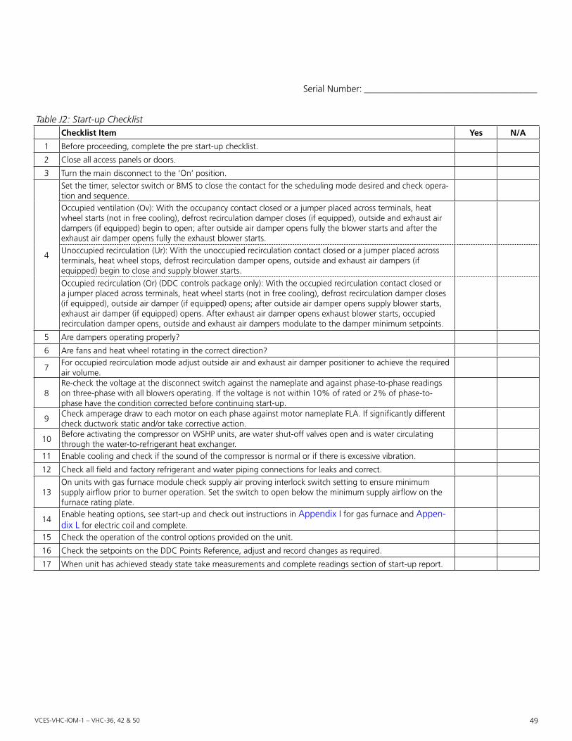
vces-vHc-iom-1 – vHc-36, 42 & 50 49
Table J2: Start-up ChecklistChecklist Item Yes n/a
1 Before proceeding, complete the pre start-up checklist.
2 Close all access panels or doors.
3 Turn the main disconnect to the ‘On’ position.
4
Set the timer, selector switch or BMS to close the contact for the scheduling mode desired and check opera-tion and sequence.Occupied ventilation (Ov): With the occupancy contact closed or a jumper placed across terminals, heat wheel starts (not in free cooling), defrost recirculation damper closes (if equipped), outside and exhaust air dampers (if equipped) begin to open; after outside air damper opens fully the blower starts and after the exhaust air damper opens fully the exhaust blower starts.Unoccupied recirculation (Ur): With the unoccupied recirculation contact closed or a jumper placed across terminals, heat wheel stops, defrost recirculation damper opens, outside and exhaust air dampers (if equipped) begin to close and supply blower starts.
Occupied recirculation (Or) (DDC controls package only): With the occupied recirculation contact closed or a jumper placed across terminals, heat wheel starts (not in free cooling), defrost recirculation damper closes (if equipped), outside air damper (if equipped) opens; after outside air damper opens supply blower starts, exhaust air damper (if equipped) opens. After exhaust air damper opens exhaust blower starts, occupied recirculation damper opens, outside and exhaust air dampers modulate to the damper minimum setpoints.
5 Are dampers operating properly?
6 Are fans and heat wheel rotating in the correct direction?
7For occupied recirculation mode adjust outside air and exhaust air damper positioner to achieve the required air volume.
8Re-check the voltage at the disconnect switch against the nameplate and against phase-to-phase readings on three-phase with all blowers operating. If the voltage is not within 10% of rated or 2% of phase-to-phase have the condition corrected before continuing start-up.
9Check amperage draw to each motor on each phase against motor nameplate FLA. If significantly different check ductwork static and/or take corrective action.
10Before activating the compressor on WSHP units, are water shut-off valves open and is water circulating through the water-to-refrigerant heat exchanger.
11 Enable cooling and check if the sound of the compressor is normal or if there is excessive vibration.
12 Check all field and factory refrigerant and water piping connections for leaks and correct.
13On units with gas furnace module check supply air proving interlock switch setting to ensure minimum supply airflow prior to burner operation. Set the switch to open below the minimum supply airflow on the furnace rating plate.
14Enable heating options, see start-up and check out instructions in Appendix I for gas furnace and Appen-dix L for electric coil and complete.
15 Check the operation of the control options provided on the unit.
16 Check the setpoints on the DDC Points Reference, adjust and record changes as required.
17 When unit has achieved steady state take measurements and complete readings section of start-up report.
Serial Number: _____________________________________

vces-vHc-iom-1 – vHc-36, 42 & 50 50
Table J3: Start-up ReadingsMode of operation Heating Cooling
Power supply
Nameplate voltage
Voltage at discon-nect no motors
L1–L2L2–L3L1–L3
Power supply with all loads connected
Voltage at full load L1/L2/L3
Supply fan
Fan load ampsAmp draw L1/L2/L3Overload amp settingRPMHertz
Exhaust fan
Full load ampsAm draw L1/L2/L3Overload amp settingRPMHertz
Condenser fan #1 amp draw – L1/L2/L3Condenser fan #2 amp draw – L1/L2/L3
Airside
Airflow CFMSupplyExhaustOccupied recirculation
Temperature °F db/wb
Outdoor enteringSupply enthalpy wheel enteringSupply enthalpy wheel leavingCooling coil leavingHeating coil leavingReheat coil leavingSupply leavingReturn enteringExhaust enthalpy wheel leaving
Static pressure inches w.c.
Outdoor ductSupply enthalpy wheel enteringSupply enthalpy wheel leavingSupply fan enteringSupply ductReturn ductExhaust enthalpy wheel enteringExhaust enthalpy wheel leavingExhaust duct
WSHP waterside
US GPMEntering temperature – °FLeaving temperature – °FEntering pressure – PSILeaving pressure – PSI
Start-up Readings• Allow unit to reach steady state before taking readings.• Complete based on options included with the unit.
Serial Number: _____________________________________

vces-vHc-iom-1 – vHc-36, 42 & 50 51
Table J3: Start-up ReadingsMode of operation Heating Cooling
Compressor refrigerant side
Circuit #1
Discharge pressure – PSISuction pressure – PSIDischarge temperature – °FSuction temperature – °FSuperheat – °FSubcooling – °FSite glass oil level __½ __¾ __FSite glass clear __Yes __NoAmps – L1/L2/L3
Circuit #2
Discharge pressure – PSISuction pressure – PSIDischarge temperature – °FSuction temperature – °FSuperheat – °FSubcooling – °FSite glass oil level __½ __¾ __FSite glass clear __Yes __NoAmps – L1/L2/L3
Gas furnace
__Natural gas __PropaneInlet pressure – inches w.c.Low fire manifold pressure – inches w.c.High fire manifold pressure – inches w.c.Supply air inlet temperature – °FSupply air discharge temperature – °F
Electric heating
Stage 1 2 3 4 5 6Amp draw – L1Amp draw – L2Amp drave – L3
This unit has been checked out and started according with the above procedures and completed forms and is oper-ating satisfactorily. After 24 hours of satisfactory opera-tion, shut down the unit and check all foundation bolts, shaft bearings, drive set screws, valve train and terminals. Tighten where required.
Additional Comments: _____________________________
_________________________________________________
_________________________________________________
_________________________________________________
_________________________________________________
_________________________________________________
_________________________________________________
Start-upBy _______________________________________________ Company Name ___________________________________ Date _____________________________________________ Email ____________________________________________ Telephone ________________________________________
Email to Tech Support ([email protected]) or fax to 306-244-4221.
Serial Number: _____________________________________

vces-vHc-iom-1 – vHc-36, 42 & 50 52
Table K1: VHC-36, 42 and 50 Troubleshootingproblem Cause Solutions
Unit will not turn on.Occupancy contact open. Check external wiring.Unoccupied recirc contact open. Check the wiring in the control panel.
Unit will not turn off.Occupancy contact closed. Check the external wiring.Unoccupied recirc contact closed. Check the wiring on the control panel.
Air from supply diffusers too cold. Imbalance of supply and exhaust air.Check filters and heat exchanger for blockage.Check balance of airflows.Install post heat module.
Unit makes an annoying noise.Blower wheel out of alignment.
Remove the motor/blower assembly.Adjust blower wheel.
Enthalpy wheel wiper seal not func-tioning properly.
Check for proper seal operation.
Enthalpy wheel freezing.Imbalance of supply and exhaust air.
Check filters and heat exchanger for blockage.Check balance of airflows.
Defrost damper not functioning. Check for operation of damper actuator.Preheater not functioning. Check for operation of damper actuator.
Enthalpy wheel not running.
Unit is in free cooling. Check jumper wire for proper operation.Unit is in recirc defrost. Check unit circuit breaker.Drive motor capacitor failure. Check motor electrical connections.
Drive motor failure.Check capacitor connections. Check motor operation with a new capacitor.
Drive motor relay in control box. Check relay wiring.
Drive belt.Check for drive belt derailment off drive pulley or failure.
Drive pulley. Check for securely fastened pulley on motor shaft.
Motor and blower not functioning.
Electrical supply interrupted. Check unit circuit breaker.Fan motor capacitor. Check motor electrical connections.Fan motor failure. Check capacitor connections.Fan motor contactor failure. Check contactor wiring. Check contactor operation.Fan drive belt. Check for a tripped overload relay.
Fan drive pulleys.Check for securely fastened pulley(s) on motor or fan shaft(s). Set screw setting at 100 in-lbs to 130 in-lbs.
Only supply fan will turn on.
Unit is in recirc defrost (recirc units). Wait until unit is out of defrost.Unit is in unoccupied recirc (recirc units).
Check external wiring.
Damper end switch not made.Check outdoor air damper for proper wiring.Check that the end switch is making.
Only exhaust fan will turn on.Unit is in defrost (exhaust units).
Check connection to motor.Motor wiring incorrect.Damper end switch not made. Check exhaust air damper for proper wiring.
Damper will not open.Electrical supply interrupted. Check wiring on damper actuator.Defrost relay in control box. Check relay wiring. Check relay operation.
Damper opens when it should be closed.
Wires are reversed. Reverse wires #2 and #3 on damper actuator.
Compressor will not turn.
No power.Ensure main disconnect is on and measure main termi-nal block for voltage.
Wiring is incorrect. Verify if compressor is wired correctly.Controlled temperature lower (cooling) or higher (heating) than thermostat setting.
Adjust thermostat setting.
Compressor failed. Replace compressor.
Appendix K: Troubleshooting

vces-vHc-iom-1 – vHc-36, 42 & 50 53
Table K1: VHC-36, 42 and 50 Troubleshootingproblem Cause Solutions
Compressor runs but stops quickly.Overload, fuse burnout.
Check if voltage is too low, wiring is incorrect, wire gauge is sized correctly; replace blown fuse.
Low or high pressure switch activated.See solution for high pressure switch open and low pressure switch open.
Compressor makes an abnormal sound.
Reverse scroll operation. Reverse any two phases on the three-phase compressor.Compressor quality issue. Replace compressor.
Excessive compressor vibration. Compressor screw is loose. Tighten the screw.Compressor is running but there is no pressure buildup.
Scroll reverse operation. Reverse any two phases on the three-phase compressor.
Compressor system is normal but amps are too high.
Incorrect compressor voltage. Replace with correct voltage compressor.
High pressure switch is open in cool-ing operation.
Condenser fan failed (AC system). Check if wiring is correct; replace any failed components.
Lack of water flow (WSHP).Check if the motorized water valve is opening com-pletely and confirm loop water pumps are running.
Water flow rate is too small (WSHP).Check if pump sized correctly. If water strainer is in-stalled in line, check if strainer is too dirty.
Condenser is too dirty (AC system). Clean condenser coil.Ambient temperature exceeds ap-plication upper limit (AC system).
Consult factory for operation out of application range.
Water entering temperature exceeds application upper limit (WSHP).
Consult factory for operation out of application range.
Refrigerant overcharge. Charge correct amount of refrigerant.Non-condensable air accumulates in the coaxial coil.
Vacuum system, recharge refrigerant.
Coaxial coil scaled. Clean coaxial coil.
High pressure switch is open in heat-ing operation.
Supply fan failure. Check if wiring is correct, replace any failed components.
Outside air damper not open.Check outside air damper operation and replace actua-tor if failed.
Dx coil is too dirty. Clean Dx coil.
Supply airflow is too small.Check if components (coil, wheel, filter) are too dirty, motor is running at low speed or not and check if there is too much pressure loss in supply duct.
Refrigerant overcharge. Charge correct amount of refrigerant.
Low pressure switch is open in cool-ing operation.
TXV failed in closed position. Replace TXV.Supply blower failure. Replace TXV or filter drier.
Insufficient supply airflow.Check if components (coil, wheel, filter) are too dirty, motor is running at low speed or not and check if there is too much pressure loss in supply duct.
Loss of refrigerant charge.Check and repair any leaks in the piping and refill refrigerant.
Low pressure switch is open in heat-ing operation.
TXV failed in closed position. Replace TXV.Blocked TXV or filter drier. Replace TXV or filter drier.
Lack of water flow (WSHP).Check if motorized water valve is opening completely and confirm loop water pumps are running.
Insufficient water flow (WSHP).Check if pump is sized correctly or if water strainer is blocked.
Water entering temperature too low (WSHP).
Consult factory for operation out of application range.
Loss of refrigerant charge.Check and repair any leaks in the piping and refill refrigerant.

vces-vHc-iom-1 – vHc-36, 42 & 50 54
This electric heating coil module covered by this appen-dix is a component of a “Listed” product, subject to the guidelines of application as designated by the Certifying Agency and outlined in the appliance Manufacturer’s in-stallation and operation instructions.
The information provided in this appendix applies to the electric heating coil module, installed in the appliance and to its operation, maintenance and service. Refer to the ap-pliance manufacturer’s instructions for information related to all other components.
1 – Mechanical Installation of Electric Coil Heaters1.1.Handling1.1.1 Remove the shipping covers just before installation.1.1.2 Inspect the heater carefully and report any dam-
age to the manufacturer.Do not install a damaged heater.
1.2.InstallationHeater position1.2.1 The axis of the duct must always be perpendicular
to the face of the heater.1.2.2 The heating elements must always be installed
horizontally.Model SC or ST (Slip-in Type)
1.2.3 Cut an opening in the side of the duct.1.2.4 Slip the heater into the duct until the hole is com-
pletely covered by flanges around the heater.1.2.5 Fasten the heater to the duct with sheet metal
screws and seal openings with a suitable sealing compound.
1.2.6 If the heater is heavy, use additional hangers to support the heater.
Model FC or FT (Flanged Type)
1.2.7 Flange both ends of the duct outwards on three sides to match the heater’s flanges.
1.2.8 Fasten the heater to the duct with sheet metal screws (for heavy heaters, use nuts and bolts and additional hangers to support the heater).
1.2.9 Seal openings with a suitable sealing compound.
2 – Electrical Installation of Electric Coil Heaters2.1.Disconnect.Power.SourceDisconnect all power sources before opening the control box and working within.
2.2.Read.NameplateRead the nameplate carefully and consult wiring diagram before starting to wire.
2.3.Supply.WiresUse only wires suitable for 167°F [75°C]. Wires shall be sized according to the Canadian Electrical Code require-ments. All wires must be brought in through knock-outs.
2.4.Disconnecting.MeansInstall a disconnect switch close to the heater according to the code unless a disconnect switch is already built into the heater.
2.5.Control.Circuit.WiringUse Class 2 wiring for control circuit connections to the duct heater.
2.6.Magnetic.ContactorsIf magnetic contactors are mounted outside of the duct heater, use only contactors approved for:
• 250,000 operations when controlled by auto-reset thermal cut-out (A) and by other switching devices in series with this cut-out (thermostat, step controller, airflow switch, etc.).
• 100,000 operations when controlled by auto-reset thermal cut-out (A) alone.
• 100,000 operations when controlled by auto-reset thermal cut-out (A) plus manual reset cut-out in se-ries (A & M).
• 6,000 operations when controlled by manual reset cutout (M) alone.
2.7.External.Controls.RatingsRating of external control devices shall be suitable for han-dling the VA ratings as marked on the nameplate; other-wise, a backup relay must be used.
2.8.Airflow.InterlockHeaters are generally supplied with one extra terminal marked for fan interlock or air sensing device connection. Remove jumper between terminals I and C before con-necting the fan interlock. Select a suitable airflow sensing device of the differential pressure sensing type, with snap acting contacts. A slow make, slow brake device may cause undue cycling and in some instances chattering of the contactors. When fresh air dampers are used, make sure the heater is properly interlocked to prevent it from being energized before the damper is fully open.
Appendix L: Electric Heating Coil and Controls Information
IMpoRtant• Do not install spray humidifiers upstream of duct.
Install it downstream instead.• Do not cover the control box with thermal insulat-
ing materials.• Use special air intake louvers of weatherproof con-
struction for preheat duct heaters to avoid intake of water or snow particles.
• Make sure that motorized damper blades are not blocked with snow or dirt. Inspect the dampers regularly to ensure a suitable airflow.

vces-vHc-iom-1 – vHc-36, 42 & 50 55
3 – operating Electric Coil Heaters3.1.Minimum.AirflowEnsure that sufficient airflow as marked on the nameplate is passing through the heater. Airflow should be evenly dis-tributed across the entire face of the heater. Use air turning vane at duct elbows and splitter damper at duct branch-offs to streamline the airflow in the heater. Use suitable airflow sensing device or interlock the heater with fan. An insufficient airflow will lead to the opening of the auto-reset thermal cut-out or damage to the heating elements.
3.2.WarningThe air flowing through the duct where the heater is in-stalled shall not contain any combustible particles, nor any flammable vapor or gas.
3.3.Air.TemperatureThe air temperature should not exceed 120°F [49°C] at the heater outlet.
3.4.Minimum.Static.Pressure.and.Air.DirectionThe heater is protected by a differential pressure switch. To keep the contact of this switch closed, it is necessary to maintain a minimum total pressure of 0.07” of water for a constant flow.
3.5.Manual.Reset.Thermal.Cut-outThis protection device is standard on all heaters of less than 300 volt and 30 kW and is optional on all other heat-ers. Please check the auto-reset thermal cut-out before resetting the manual thermal cut-out. If any defect has been detected in the auto-reset thermal cut-out, it will be necessary to replace it before resetting the manual reset thermal cut-out.
4 – MaintenanceAll electric coil heaters have been designed to operate long term without problems. Those responsible for equip-ment and maintenance should be aware of the following suggestions.
4.1.Visual.InspectionIt is strongly recommended to complete a periodic inspec-tion. This precautionary step will help to keep your instal-lations operating well. Note these eventual first signs of problems:
• Accumulation of dust on the heating elements.• Signs of overheating on the heater frame.• Traces of water or rust on the control box.
4.2.Electrical.InspectionTwo weeks after start-up, all electric connections to con-tactors should be checked and tightened up. Before each heating season, check the resistance between the heating
elements and ground. It is also recommended to check the electrical connections to heating elements, magnetic contactors and main power lugs. This inspection is recom-mended monthly during the first four months of operation. After that, two inspections per heating season are sufficient.
4.3.Checkpoints• Check all fuses.• Check the resistance to ground for each circuit.• Check the resistance phase-to-phase for each circuit.• Check the tightening of connections at all contactors
and heating elements.• Check all contactors.
4.4.Off-season.MaintenanceWhere tubular heating elements are used, it is strongly recommended that you start the heating system from time to time. This precaution will prevent moisture from percolating through the terminal gaskets into the heat-ing element and accumulating in the insulating powder. Should a heater be shut off for a long period, we recom-mend that you check carefully the resistance to ground for each circuit. It is important not to power a heater when too low a resistance to ground has been measured. It is also recommended to pay attention to any other heater operating in normal conditions. Control components such as step controllers or modulating valves (SCR) should be maintained and checked according to respective Manufac-turer’s instructions. Any defective components should be replaced only with identical original parts.

vces-vHc-iom-1 – vHc-36, 42 & 50 56
Functional DescriptionsHead.Pressure.ControlA three-way modulating head pressure control valve is required to maintain stable operation of the refrigeration systems when operated on ground loop water systems when the design water temperature is below 65°F in the cooling mode. A refrigerant pressure sensor on the com-pressor discharge is used to modulate the water flow to the condenser using a 2 to 10 VDC signal to artificially keep the compressor discharge pressure at a high enough operating condition to prevent the low pressure refriger-ant switch from tripping.
The three-way modulating head pressure control valve consists of a 24 VAC NEMA 1 or 2 modulating actua-tor with a temperature rating of −22°F to 122°F [−30°C to 50°C], nickel plated forged brass valve with stainless steel ball, stem and replaceable valve cartridge assembly which is an option and must be externally field mounted. For outdoor applications a NEMA 4x rated actuator must be installed. The hydronic valves are intended for use in a normal indoor/outdoor environment for hot or cold water or glycol solutions to 60% concentration with a medium temperature rating of 0°F to 212°F [−18°C to 100°C]. The valve and actuator are preassembled for 100% flow to the coil with minimum of 2 VDC signal. The refrigerant pres-sure sensor is internally factory mounted, prewired and programmed for the DDC to control the three-way valve. A 6 foot coiled wiring harness is factory supplied with the unit, located in the compressor compartment for field ex-tension and wiring to the actuator.
See Table M2 for three-way valve sizing and performance data. Dimensions, technical and installation data follow. See the wiring schematic for connection and the VHC-36, 42 and 50 DDC Control Package Manual for sequencing infor-mation.
Water Shut-offA two-way motorized on/off water shut-off valve is re-quired to isolate water flowing through both the econo-mizer coil (if equipped) and water-to-refrigerant condenser for conservation when the unit is off. The water shut-off valve must be placed upstream of the economizer coil and three-way economizer control valve and the three-way modulating head pressure control valve (if equipped). The motorized water valve must open 90 seconds prior to compressor start-up and remain open five seconds after the compressor is shut off.
The two-way motorized water shut-off valve is an ac-cessory item and consists of a 24 VAC NEMA 1 or 2 on/off actuator with a temperature rating of −22°F to 122° F [−30°C to 50°C], nickel plated forged brass valve and replaceable valve cartridge assembly which is an accessory and must be externally field mounted. For outdoor appli-
Appendix M: Water Line Field Mounted Options and Accessories
IMpoRtant• Water source heat pump external water supply
and return piping shall be in accordance with Na-tional and Local Codes. Line sizing, pressure limit-ing devices, backflow preventers, strainers, valves, flow temperature and pressure measuring, freeze protection and all other safety or control piping requirements for system operation are the sole responsibility of the Installing Contractor and/or De-sign Engineer.
• Some external piping components and control inter-locks are offered as an option or accessory for partly field and factory installation and are summarized in Table M1. A detailed functional description follows.
• On open loop systems, a field supplied and installed water strainer (16–20 mesh minimum) is recom-mended in the water inlet or supply line to the unit to eliminate contaminants and must be used for 14, 16 and 21 ton dual circuit WSHP units which utilize a brazed plate heat exchanger condenser.
• Air vents must be field installed on the high side of the water supply or inlet line to discharge the noncondensable air in order to avoid unexpected high head pressure and poor cooling/heating per-formance.
• Manual shut-off valves in supply and return water lines are recommended to be field installed for isola-tion and service.
• A circuit balancing valve with pressure and tempera-ture gauge connections is recommended to be field supplied and installed for balancing and service. The water supply must be sized for the minimum flow as indicated on the submittals.
• Prior to connection of condensing water supply, verify water pressure is less than the maximum pres-sure for components in the water line. To prevent injury or death due to instantaneous release of high pressure water, relief valves should be field supplied and installed in system water piping.
• Maximum working pressure, pressure drop or Cv factors for condenser and optional or accessory components are given in tables below.
Table M1: WSHP Water Line Option or AccessoryFunction Field Installed Factory Installed
Head pressure control
Three-way water control valve with modulating actuator
Head pressure control DDC program logicRefrigerant pressure transducer
Water shut-off
Two-way water shut-off valve with on/off actuator
Water on/off control DDC program logic
Freeze protection
Water flow switch
Unit on/off control DDC program logicWater outlet tempera-ture sensor

vces-vHc-iom-1 – vHc-36, 42 & 50 57
cations a NEMA 4x rated actuator must be installed. The hydronic valves are intended for use in a normal indoor/outdoor environment for hot or cold water or glycol solu-tions to 60% concentration with a medium temperature rating of 0°F to 212°F [−18°C to 100°C]. The actuator must be field wired to the standard field wiring (FW) ter-minals #435, 436 and 437 depending on valve size. The valve and actuator are preassembled for 0% flow to the coil when the unit does not require heating or cooling.
See Table M3 for two-way valve sizing, performance data and dimensions; installation and technical data is included with accessory parts. See the wiring schematic for connec-tion information.
Freeze protectionA water flow switch and a temperature sensor as an op-tion and mounted on the water return or leaving side of the condenser are used to monitor the presence or ab-sence of flow and the water temperature which will shut down the compressor and unit for freeze protection. The flow switch also features an adjustment which allows the user to change the switch from normally open (NO) to normally closed (NC).
The temperature sensor is factory mounted and wired in-ternally. The flow switch must be externally field mounted in the leaving or return water line and field wired to the standard field wiring (FW) terminal strip as per wiring schematic. See performance, dimensions and installation data at the end of this appendix.
Table M2: Three-way Valve Sizing and Performance Data
tonsMinimum uS
gpMCondenser pressure
Drop (pSI)
Condenser Maximum
pressure (pSI)
three-way Head pressure Control Valve
CvMaximum pressure
(pSI)*Size Fpt
2 6 4.3 400 3.0 600 ½
3 9 9.2 400 3.0 600 ½
4 12 3.0 400 4.7 600 ¾
5 15 5.0 400 7.4 600 ¾
6 18 7.0 400 7.4 600 1
8 24 7.7 400 7.4 600 1
10 30 4.3 400 10.0 400 1¼
12 36 7.0 100 19.0 400 1¼
14 42 6.0 400 19.0 400 1¼
*Maximum close off pressure 200 psi.
Table M3: Two-way Valve Sizing and Performance Data
tonsMinimum uS
gpMCondenser pressure
Drop (pSI)
Condenser Maximum
pressure (pSI)
two-way Water Shut-off Valve
CvMaximum pressure
(pSI)*Size Fpt
2 6 4.3 400 24 600 ¾
3 9 9.2 400 24 600 ¾
4 12 3.0 400 24 600 ¾
5 15 5.0 400 24 600 ¾
6 18 7.0 400 19 400 1¼
8 24 7.7 400 19 400 1¼
10 30 4.3 400 19 400 1¼
12 36 7.0 100 37 400 1½
*Maximum close off pressure 200 psi.

vces-vHc-iom-1 – vHc-36, 42 & 50 58
Table M6: Indoor Three-way Valve Dimensions (2 to 5 tons)Value nominal Size Dimensions (Inches [mm])Inches Dn [mm] a B C
½” 15 mm 2.41” [61.1] 1.39” [35.2] 1.20” [30.6]½” 15 mm 2.38” [60.4] 1.72” [43.7] 1.26” [32.1]¾” 20 mm 2.73” [69.3] 1.81” [45.9] 1.45” [36.8]
2.50”[63.5 mm]
C
2.82”[71.6 mm]
B
3.25”[82.6 mm]
A
Figure M1: Indoor three-way valve actuator (2 to 5 tons)
Table M5: Indoor Three-way Valve Actuator Technical and Dimensional Data (2 to 5 tons)Control On/off, floating pointNominal voltage 24 VAC 50/60 HzNominal voltage range 19.2–28.8 VACPower consumption 1 WTransformer sizing 1 VA (Class 2 power source)
Electrical connectionScrew terminals accessible after removal of small cover (3 feet, 10 feet, 16 feet cables optional)
Input impedance 0.36kΩAngle of rotation 90°Position indication Integrated into handleManual override Push down handle
Running time90 seconds at 60 Hz, 108 seconds at 50 Hz
Humidity 5–95% non-condensingAmbient temperature −22° to 122°F [−30°C to 50°C]Storage temperature −40°F to 176°F [−40°C to 80°C]Housing NEMA 1/IP40Housing rating UL94-5V (B)
Agency listing*cULusa ac. to UL60730-1A/-2- 14, CAN/CSA E60730-1, CSA C22.2 No. 24-93, CE acc. to 89/336/EEC
Noise level Max. 35 db (A)Quality standard ISO 9001*Rated impulse voltage 330V, control pollution degree 2, type of action 1
Table M4: Three-way Technical DataService Chilled or hot water, 60% glycol
Flow characteristic
A-port B-port
Equal percentageModified for constant com-mon port flow
Action 90° rotationSizes ½”, ¾”, 1”, 1¼”, 1½”, 2”Type of end fitting NPT female endsMaterialsBody Forged brass, nickel platedBall and stem Stainless steelSeats PTFECharacterizing disc Tefzel®
Packing 2 EPDM O-rings, lubricatedBody pressure rating 600 PSI 400 PSI
½”–1” 1¼”–2”Media temperature range 0°F to 212°F [−18°C to 100°C]Close off pressure – 200 PSI ½”–2”Maximum differential pres-sure (∆P)
30 PSI for typical applications
LeakageA to AB B to AB0% <2%
Cv ratingA-port B-portSee product chart for values
70% of A to AB Cv
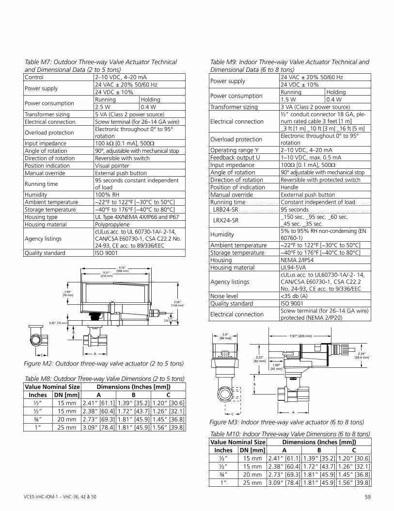
vces-vHc-iom-1 – vHc-36, 42 & 50 59
C
B
A
0.62” [16 mm]
2.99”[76 mm]
1.0”[25.5 mm]
5.28”[134 mm]
9.76”[248 mm]9.21”
[234 mm]
Figure M2: Outdoor three-way valve actuator (2 to 5 tons)
Table M7: Outdoor Three-way Valve Actuator Technical and Dimensional Data (2 to 5 tons)Control 2–10 VDC, 4–20 mA
Power supply24 VAC ± 20% 50/60 Hz24 VDC ± 10%
Power consumptionRunning Holding2.5 W 0.4 W
Transformer sizing 5 VA (Class 2 power source)Electrical connection Screw terminal (for 26–14 GA wire)
Overload protectionElectronic throughout 0° to 95° rotation
Input impedance 100 kΩ [0.1 mA], 500ΩAngle of rotation 90°, adjustable with mechanical stopDirection of rotation Reversible with switchPosition indication Visual pointerManual override External push button
Running time95 seconds constant independent of load
Humidity 100% RHAmbient temperature −22°F to 122°F [−30°C to 50°C]Storage temperature −40°F to 176°F [−40°C to 80°C]Housing type UL Type 4X/NEMA 4X/IP66 and IP67Housing material Polypropylene
Agency listingscULus acc. to UL 60730-1A/- 2-14, CAN/CSA E60730-1, CSA C22.2 No. 24-93, CE acc. to 89/336/EEC
Quality standard ISO 9001
C
2.6”[66 mm]
2.34”[59.4 mm]
7.97” [200 mm]
A
B
1.69”[42 mm]
3.22”[82 mm]
Figure M3: Indoor three-way valve actuator (6 to 8 tons)
Table M8: Outdoor Three-way Valve Dimensions (2 to 5 tons)Value nominal Size Dimensions (Inches [mm])
Inches Dn [mm] a B C½” 15 mm 2.41” [61.1] 1.39” [35.2] 1.20” [30.6]½” 15 mm 2.38” [60.4] 1.72” [43.7] 1.26” [32.1]¾” 20 mm 2.73” [69.3] 1.81” [45.9] 1.45” [36.8]1” 25 mm 3.09” [78.4] 1.81” [45.9] 1.56” [39.8]
Table M9: Indoor Three-way Valve Actuator Technical and Dimensional Data (6 to 8 tons)
Power supply24 VAC ± 20% 50/60 Hz24 VDC ± 10%
Power consumptionRunning Holding1.5 W 0.4 W
Transformer sizing 3 VA (Class 2 power source)
Electrical connection½” conduit connector 18 GA, ple-num rated cable 3 feet [1 m]_3 ft [1 m] _10 ft [3 m] _16 ft [5 m]
Overload protectionElectronic throughout 0° to 95° rotation
Operating range Y 2–10 VDC, 4–20 mAFeedback output U 1–10 VDC, max. 0.5 mAInput impedance 100Ω [0.1 mA], 500ΩAngle of rotation 90° adjustable with mechanical stopDirection of rotation Reversible with protected switchPosition of indication HandleManual override Exxternal push buttonRunning time Constant independent of loadLRB24-SR 95 seconds
LRX24-SR_150 sec. _95 sec. _60 sec. _45 sec. _35 sec.
Humidity5% to 95% RH non-condensing (EN 60760-1)
Ambient temperature −22°F to 122°F [−30°C to 50°C]Storage temperature −40°F to 176°F [−40°C to 80°C]Housing NEMA 2/IP54Housing material UL94-5VA
Agency listingscULus acc. to UL60730-1A/-2- 14, CAN/CSA E60730-1, CSA C22.2 No. 24-93, CE acc. to 9/336/EEC
Noise level <35 db (A)Quality standard ISO 9001
Electrical connectionScrew terminal (for 26–14 GA wire) protected (NEMA 2/IP20)
Table M10: Indoor Three-way Valve Dimensions (6 to 8 tons)Value nominal Size Dimensions (Inches [mm])
Inches Dn [mm] a B C½” 15 mm 2.41” [61.1] 1.39” [35.2] 1.20” [30.6]½” 15 mm 2.38” [60.4] 1.72” [43.7] 1.26” [32.1]¾” 20 mm 2.73” [69.3] 1.81” [45.9] 1.45” [36.8]1” 25 mm 3.09” [78.4] 1.81” [45.9] 1.56” [39.8]

vces-vHc-iom-1 – vHc-36, 42 & 50 60
C
B
A
0.62” [16 mm]
2.99”[76 mm]
1.0”[25.5 mm]
5.28”[134 mm]
9.76”[248 mm]9.21”
[234 mm]
Figure M4: Outdoor three-way valve actuator (6 to 8 tons)
C
3.46”[88 mm] 8.5” [216 mm]
3.3”[84 mm]
B
A
2.49”[63.4 mm]
1.35”[35 mm]
Figure M5: Indoor three-way valve actuator (10 to 21 tons)
Table M11: Outdoor Three-way Valve Actuator Technical and Dimensional Data (6 to 8 tons)
Power supply24 VAC ± 20% 50/60 Hz24 VDC ± 10%
Power consumptionRunning Holding2.5 W 0.4 W
Transformer sizing 5 VA (Class 2 power source)Electrical connection Screw terminal (for 26–14 GA wire)
Overload protectionElectronic throughout 0° to 95° rotation
Operating range Y 2–10 VDC, 4–20 mAInput impedance 600ΩAngle of rotation 90° adjustable with mechanical stopDirection of rotation Reversible with switchPosition indication Visual pointerManual override External push button
Running time95 seconds constant independent of load
Humidity 100% RHAmbient temperature −22°F to 122°F [−30°C to 50°C]Storage temperature −40°F to 176°F [−40°C to 80°C]Housing type UL Type 4X/NEMA 4X/IP66 & IP67Housing material Polypropylene
Agency listings†cULus acc. to UL60730-1A/-2- 14,CAN/CSA E60730-1, CSA C22.2 No. 24-93, CE acc. to 89/336/EEC
Quality standard ISO 9001† Rated impulse voltage 800V, type of action 1, control population degree 3.
Table M12: Outdoor Three-way Valve Dimensions (6 to 8 tons)Value nominal Size Dimensions (Inches [mm])
Inches Dn [mm] a B C1¼” 32 mm 3.96” [100.6] 2.21” [56.2] 2.14” [54.3]1½” 40 mm 4.39” [111.6] 2.45” [62.2] 2.33” [59.1]2” 50 mm 4.90” [124.5] 2.68” [68.0] 2.60” [66.0]
Table M13: Indoor Three-way Valve Actuator Technical and Dimensional Data (10 to 21 tons)
Power supply24 VAC ± 20% 50/60 Hz24 VDC ± 10%
Power consumptionRunning Holding2.5 W 0.4 W
Transformer sizing 3 VA (Class 2 power source)
Electrical connection½” conduit connector 18 GA ple-num rated cable_3 ft [1 m] _10 ft [3 m] _16 ft [5 m]
Overload protectionElectronic throughout 0° to 95° rotation
Operating range Y 2–10 VDC, 4–20 mAFeedback output U 1–10 VDC, max. 0.5 mAInput impedance 100Ω [0.1 mA], 500ΩAngle of rotation 90° adjustable with mechanical stopTorque 180 in-lb [20 Nm]Direction of rotation Reversible with switchPosition indication HandleManual override External push button
Running time95 seconds constant independent of load
Humidity5% to 95% RH non-condensing (EN 60730-1)
Ambient temperature −22°F to 122°F [−30°C to 50°C]Storage temperature −40°F to 176°F [−40°C to 80°C]Housing NEMA 2/IP54Housing material UL94-5VA
Agency listings†cULus acc. to UL60730-1A/-2- 14,CAN/CSA E60730-1, CSA C22.2 No. 24-93, CE acc. to 89/336/EEC
Noise level <45 db (A)Quality standard ISO 9001† Rated impulse voltage 800V, control pollution degree 3, type of ac-tion1 (1.B for -S models)
Table M14: Indoor Three-way Valve Dimensions (10 to 21 tons)Value nominal Size Dimensions (Inches [mm])
Inches Dn [mm] a B C1¼” 32 mm 3.96” [100.6] 2.21” [56.2] 2.14” [54.3]1½” 40 mm 4.39” [111.6] 2.45” [62.2] 2.33” [59.1]2” 50 mm 4.90” [124.5] 2.68” [68.0] 2.60” [66.0]

vces-vHc-iom-1 – vHc-36, 42 & 50 61
10.66”1.52”
9.56”1.10”
2.01”
5.28”
0.21”
5.52”
5.15” 4.41”
AM..N4 9/10”...3/4” 3/8”...9/10” 9/10”...3/4”
4.88”
Figure M6: Outdoor three-way valve actuator (10 to 21 tons)
C
B
A
Figure M7: Actuator
Table M15: Outdoor Three-way Valve Actuator Technical and Dimensional Data (10 to 21 tons)
Power supply24 VAC ± 20% 50/60 Hz24 VDC ± 10%
Power consumptionRunning Holding2.5 W 0.4 W
Transformer sizing 5 VA (Class 2 power source)
Electrical connectionScrew termianl (for 26–14 GA wire) ½” conduit connector
Overload protectionElectronic throughout 0° to 95° rotation
Operating range Y 2–10 VDC, 4–20 mAFeedback output U 1–10 VDC, max. 0.5 mAInput impedance 100Ω [0.1 mA], 500Ω
Angle of rotationMax 95° adjustable with mechani-cal stop
Torque 160 in-lb [16 Nm]Direction of rotation Reversible with switchPosition indication PointerManual override External push button
Running time95 seconds constant independent of load
Humidity5% to 95% RH non-condensing (EN 60730-1)
Ambient temperature −22°F to 122°F [−30°C to 50°C]Storage temperature −40°F to 176°F [−40°C to 80°C]Housing IP66/67 UL Type 4X, NEMA 4XHousing material UL94-5VA
Agency listings†cULus acc. to UL60730-1A/-2- 14,CAN/CSA E60730-1, CSA C22.2 No. 24-93, CE acc. to 89/336/EEC
Noise level <45 db (A)Servicing Maintenance freeQuality standard ISO 9001Weight 3.3 lbs [1.5 kg]† Rated impulse voltage 800V, type of action 1, control pollution degree 3
Table M16: Outdoor Three-way Valve Dimensions (10 to 21 tons)Value nominal Size Dimensions (Inches [mm])
Inches Dn [mm] a B C1¼” 32 mm 3.96” [100.6] 2.21” [56.2] 2.14” [54.3]1½” 40 mm 4.39” [111.6] 2.45” [62.2] 2.33” [59.1]2” 50 mm 4.90” [124.5] 2.68” [68.0] 2.60” [66.0]
Table M17: Actuator SpecificationsTorque 162 in-lbs [18 Nm]
Angle of rotation95° (adjustable with mechanical stops)
Fits shaft diameter 9/16”...3/4”
Manual override External push button
Direction of rotation External switch
Dimensions10.66” x 5.28” x 4.88” [271 x 134 x 124 mm]
Electrical connection Terminal strip
Overload connection Electronic throughout rotation
Auxiliary switch(es)Add on: 1 or 2 SPDT, 3A (0.5A inductive) at 250V one switch adjustable 25° to 85°
Housing specifications NEMA 4/4X, IP66/IP67
Agency listings
cULus according to UL 30730-1A/- 2-14, CAN/CSA E60730-1:02, CE according to 2004/108/EC and 2006/95/EC
Control shaft lengthMinimum ¾”
Maximum 2¼”

vces-vHc-iom-1 – vHc-36, 42 & 50 62
Water Valve piping arrangementIt is important to follow the proper piping arrangement for both two-way and three-way water valves. Incorrect piping arrangements will damage the unit. The field piping schematic is illustrated below.
For two-way ValveTwo-way valves should be installed in accordance to the arrow direction marked on the valve body for the water inlet or supply line. Two-way valves should be installed with the disc upstream. If installed with disc downstream, flow curve will be deeper. If installed “backwards” it is not necessary to remove and change. No damage or control problems will occur.
For three-way ValveThree-way valves must be installed with the ‘AB’ marked or common port to the supply water line, the ‘A’ marked or control port to the coil and the ‘B’ marked, ‘Bypass’ or middle port to the return water line.
Correct piping
Incorrect piping
Valve and actuator InstallationMount the valve directly in the pipe where the assembly will not block the system vent or other components. Do not grip the actuator while making and tightening up plumbing connections. Either hold valve body in your hand or attach adjustable wrench across the hexagonal or flat faces on the valve body. If assembling valve train on bench, take care not to deform the body with a vise.
Refrigerant components
P P P
Access valve Access valves
Scroll compressor
Switch highpressure
Crank case heaterSwitch low optionalpressure valve kit
Pressuretransducer
Pressure transducer factorymounted at compressordischarge port
Unit water inlet
Field mounted
Head pressure control valveoption
On/off valveaccessory
StrainerModulating three-way valve
Motorized valvewater shut-off
Water inlet
H B
Flowswitchoption
Water inletUnit water outlet
A
T
C B
J K
Figure M8: Water valve piping arrangement
ABA A AB
A AB 0%AB 100%
Two-way valvesshould be installedwith the discupstream.
Flow direction
A ABBelimo
A
Figure M9: Two-way valve arrangement
Diverting
A AB
B
A AB
B
A
B
A
B
AB 100% AB 0%
AB 70%AB 0%
The A-port mustbe piped to the coilto maintain propercontrol.
Figure M10: Three-way valve arrangement
1 input, 2 outputs
Coil
Return
Supply
B
A AB
Figure M11: Correct three-way diverting valve piping
1 input, 2 outputs
Coil
Return
Supply
B
A
AB
Figure M12: Incorrect three-way diverting valve piping
Figure M13: Valve installation
CautIonIf the valve is piped incorrectly, it must be re-piped as it may restrict flow and cause damage to the unit.

vces-vHc-iom-1 – vHc-36, 42 & 50 63
Water Flow SwitchFlow.Switch.Dimensions
Flow.Switch.InstallationThe flow switch must be externally field mounted in the leaving or outlet water line. Before installation, the flow switch vane must be trimmed for the size of piping being used. A full size, trimmable stainless steel vane is provided with a removable laminate template. This template is cali-brated for brass or ductile iron reducing tee and forged steel straight tee/brushing combination which allows for field installation in pipeline from ½” to 2” diameter. See Table M18 for approximate actuation and deactivation values.
1. Carefully unpack the flow switch and remove any packing material from the lower housing. Trim the vane at the appropriate mark for the size of piping being used.
2. Apply thread tape or sealant to the ½” male NPT mounting threads and install the flow switch in the system piping with the arrow on the side pointing in the direction of flow.
3. The flow switch must be field wired to the standard field wiring (FW) terminal strip as per wiring sche-matic for 24 VAC.
4. Avoid exceeding any of the maximum electrical rat-ings which can lead to failure.
5. After installation, set the switch action to normally open or normally closed. To change the switching from normally open to normally closed, loosen, but do not remove the two screws on the top cap. Slide the reed switch assembly to expose the switch action se-lected. Tighten screws when adjustment is complete.
11
22
3
3
4
4
5
5
One screw attachesactuator to valve
Four actuator mountingpositions
Two-way flow pattern
Three-way flow pattern(mixing shown)
Top of valve stem indicatesdirection of flow(Flow A to AB shown)
Note: For diverting flow, flowenters in AB and divertsto A and B ports.
CCWCCW
4 x 90°
A
A
AB
AB
B
A-AB = 100%
A-AB = 100%
B-AB = 0%
Figure M14: Valve and actuator assembly and installation
WaRnIngMechanical shock or vibration can cause permanent damage to the switch. Avoid dropping the unit on hard surfaces.
!
Figure M15: Valve and actuator assembly and installation
2¼” [57 mm]
1” [25 mm]¼ (6) travel to normally closed position
(2) 22 AWG Leadwires18 (460) long
1/8 NPT – switch shownin normally open position
Lower body
7/8 hex
½ NPTM
Vane 2-7/16” [62 mm]
2-7/8” [73 mm]
Table M18: Flow Switch Performance Data TableCold Water Flow Rates –
approximate actuation/Deactuationpipe trim no nC
½” L2.6/2.3 2.6/2.5
9.8/8.7 9.8/9.5
¾” J3.1/2.7 3.1/2.8
11.7/10.2 11.7/10.6
1” H4.8/4.5 4.8/4.4
18.2/17.0 18.2/16.7
1¼” E6.2/5.6 6.1/5.6
23.5/21.2 23.1/21.2
1½” C8.2/7.7 8.2/7.7
31.0/29.1 31.0/29.1
2” Full9.5/9.1 9.5/9.0
36.0/34.4 36.0/34.1
GPM upper, LPM lower

vces-vHc-iom-1 – vHc-36, 42 & 50 64
Appendix N: Enthalpy Wheel Pressure Drop vs. Flow Formulae and Curves
Enthalpy Wheel pressure Drop vs. Flow FormulaFlow in cfm = pressure drop measured in ” w.c. / pressure drop coefficient based on enthalpy wheel size
Enthalpy Wheel pressure Drop vs. cfm Curves (based on wheel diameter x depth (inches))
Table N1: Enthalpy Wheel Pressure Drop CoefficientEnthalpy Wheel Size
(diameter x depth in inches)pressure Drop
Coefficient36 x 4 0.00029551
36 x 6 0.00032675
36 x 8 0.00038283
42 x 4 0.00021504
42 x 6 0.00023397
42 x 8 0.00027220
50 x 4 0.00014783
50 x 6 0.00016034
50 x 8 0.00018639
0.5
0.6
0.7
0.8
0.9
1.0
0.4
0.3
0.1
0.2
0.00 500 1,000 1,500 2,000 2,500 3,000
Airflow [cfm]
Pres
sure
Dro
p [
in. w
.g.]
36” x 8” (High)
36”x 6” (Standard)
36” x 4” (Medium)
Figure N1: Pressure drop – 36” enthalpy wheel diameter
0.5
0.6
0.7
0.8
0.9
1.0
0.4
0.3
0.1
0.2
0.00 500 1,000 1,500 2,000 2,500 3,000 3,500 4,000
Airflow [cfm]
Pres
sure
Dro
p [
in. w
.g.]
42” x 8” (High)
42”x 6” (Standard)
42” x 4” (Medium)
Figure N2: Pressure drop – 42” enthalpy wheel diameter
0.5
0.6
0.7
0.8
0.9
1.1
1.0
0.4
0.3
0.1
0.2
0.00 1,000 2,000 3,000 5,000 6,0004,000
Airflow [cfm]
Pres
sure
Dro
p [
in. w
.g.]
50” x 8” (High)
50”x 6” (Standard)
50” x 4” (Medium)
Figure N3: Pressure drop – 50” enthalpy wheel diameter

©2012 Venmar CES Inc.VCES-VHC-IOM-1 (PN 216013)
August 2012
Venmar CES Inc. has a policy of continuous improvement and reserves the right to change design and specifications without notice.


