Download - Installation, Operation & Maintenance PSCS
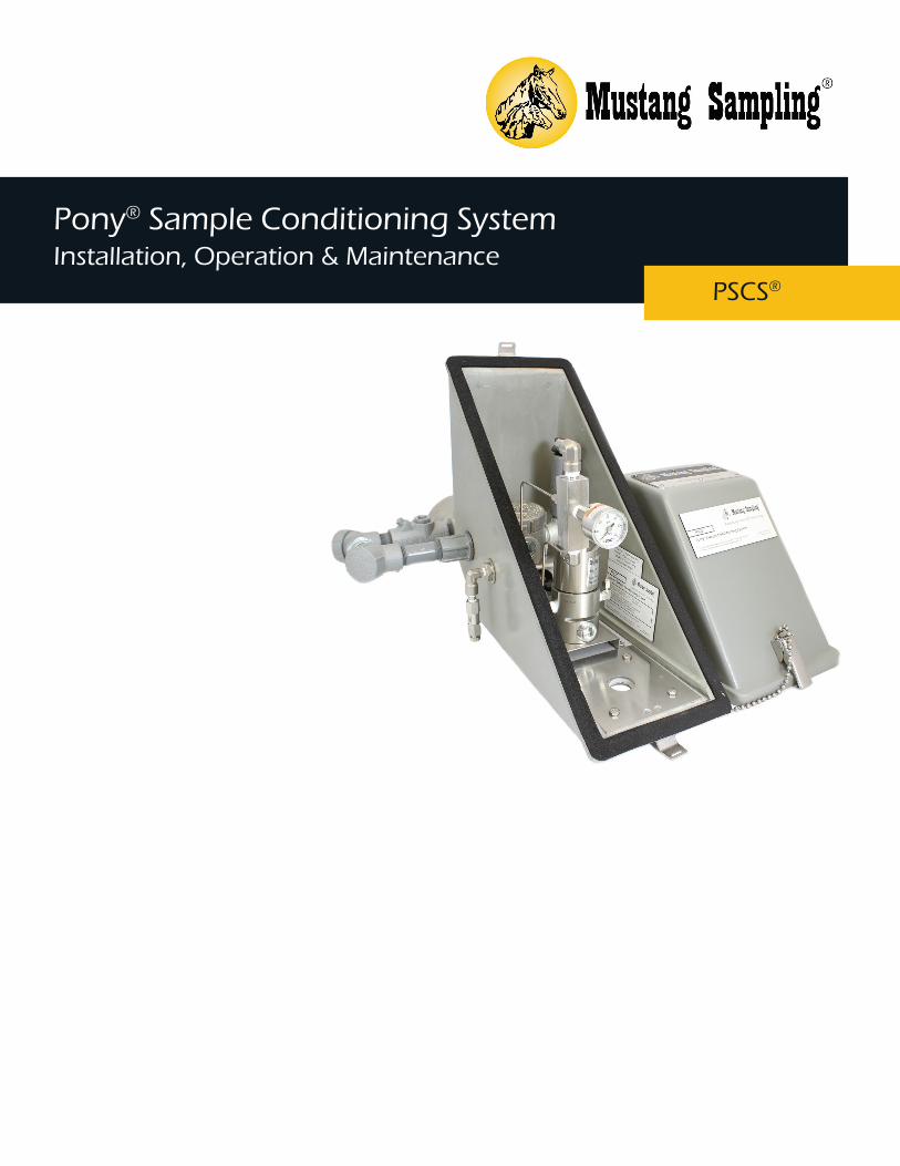
Pony® Sample Conditioning SystemInstallation, Operation & Maintenance
PSCS®

2
TABLE OF CONTENTS
Safety Warnings 3
Product Features 4
Watlow® Controller
Technical Specifications 5
Product Dimensions & Parts 6
Process & Instrumentation Diagram 8
Electrical Wiring Diagrams 9
Installation Instructions 11
Operation Instructions 12
Maintenance Instructions 12
Oven Industries Controller
Technical Specifications 13
Product Dimensions & Parts 14
Process & Instrumentation Diagram 16
Electrical Wiring Diagrams 17
Installation Instructions 19
Operation Instructions 20
Maintenance Instructions 20

3
SAFETY WARNINGS
• Standard for Safety Electrical Equipment for Measurement, Control, and Laboratory Use; Part 1: General Requirements (ANSI/UL 61010-1, 07/12/2004, Ed. 2).
• Standard for Safety Electrical Equipment for Measurement, Control , and Laboratory Use; Part 1: General Requirements (CAN/CSA C22.2 No. 61010-1, 07/01/2004, Ed. 2).
• Standard for Safety Explosion-Proof and Dust-Ignition Proof Electrical Equipment for Use in Hazardous (Classified) Locations (ANSI/UL 1203, 1028/09, Ed. 4).
• Explosion-Proof Enclosures for Use in Class 1 Hazardous Locations Industrial: Industrial Products (CSA C22.2 No. 30-M1986, (G.I. No. 2, 11/1988)).
• Electrical power must be “OFF” before and during installation and maintenance or personal injury may result. Follow site requirements for Safety Precaution Rules.
• Do not exceed any equipment pressure, or electrical ratings.• To reduce the risk of fire or explosion, do not install where the marked operating temperature exceeds the
ignition temperature of the hazardous atmosphere(s).• Heated regulator surface temperature will approach temperature limit specified in technical specifications.• Select a mounting location so that the system will not be subjected to impact or other damaging effects.• The hazard location information specifying class and group listing of each system is marked on the
nameplate.• Properly ground all equipment to prevent static electric generation.
Failure to abide by any of the safety warnings could result in serious injury or death.

4
• Patented technology utilizing existing power supplied by heat trace tube bundle
• Molded narrow clam shell design• Rated for Class 1, Division 1, Group
D Locations• Compatible with Mustang®
CertiSeries® line of products• Steel latching closures
• Requires no external power or natural gas for proper operation
• Conforms to API 14.1 guidelines for hydrocarbon liquid removal and heat tracing
• Protects probes from temperature and weather fluctuations
• Helps preserve sample integrity• Prevents Joule-Thomson cooling• Direct-mount on pipeline fitting
between 6” center-to-center threadolets (TOLs)
• Fits over existing probe brands• Closely coupled to the sample
point
The Pony® Sample Conditioning System is ideal for sampling wet or dry natural gas when a
compact solution mounted directly to the sampling probe is preferred. The PSCS contains a
self-limiting block heater, Watlow® PID temperature controller, system temperature limiter,
and a single or multistage pressure regulator, all mounted inside a Pony® Heated Probe
Enclosure. The close coupled system reduces the opportunity for richer gases to condense
within sample tubing and protects analyzers from damage by solids or liquids while delivering
a representative sample. The Pony® Sample Conditioning System is the only probe mounted
sample conditioning system that can be powered by the heat trace tube bundle, creating a
cost effective solution for new or existing locations.
FEATURES BENEFITS
PRODUCT DESCRIPTION

5
TECHNICAL SPECIFICATIONS
Pony® Sample Conditioning SystemWatlow® Controller Model
Maximum Allowable Operating Pressure 6000 psig (408 BAR) @ 60ºF (16ºC)
Wetted Parts 316 SS Nace Compliant
Regulator Sample Volume/Cv 0.51 cu. in.
Regulator Cv 0.023
Maintains Sample Gas Standard set point at 120ºF (49ºC) Adjustable from 60ºF to 400ºF (16ºC to 204ºC)
Regulator Options MHR® Single-Stage Regulator
MJTHR® Multi-Stage Regulator
Input Supply Voltage Options 115 VAC
240 VAC
24 VDC
Cabinet Construction Options GPR Hotpressed Glass Fiber Reinforced Polyester
SS Stainless Steel

6
PRODUCT DIMENSIONS & PARTS
1
2
Item Number
Description
1 Insulated Clamshell Enclosure
2 Watlow® PID Temperature Controller
3 Single or Multi-Stage Heated Regulator
4 Probe Location3
4

7
Front View Top View

8
PROCESS & INSTRUMENTATION DIAGRAM

9
ELECTRICAL & WIRING DIAGRAMS
120 VAC

10
240 VAC

11
24 VDC

12

13
INSTALLATION INSTRUCTIONS
The Pony® Sample Conditioning System assembly can be mounted in one of several mounting configurations.1. Mount the Pony® Sample Conditioning System assembly in accordance with previous cautions and warnings.2. Perform the electrical hook up with de-energized conductors.3. Verify the unit that you are hooking up to matches voltage wise with the power supply that you are connecting.
Damage to the unit can occur if the wrong source power is applied.4. A seal fitting is required for the power input connection to the controller enclosure to maintain its electrical hazard
classification rating.5. For 120 volt single phase input power: Connect the “hot” wire to wiring terminal #1. Connect the “Neutral” wire
to wiring terminal #2. Connect the earthing (ground) wire to the green screw in the bottom of the enclosure.6. For 208 or 230 volt single phase input power: Connect one “hot” wire to wiring terminal #1. Connect the
“Neutral” to wiring terminal #2. Connect the second “hot” wire to wiring terminal #3. Connect the earthing (ground) wire to the green screw in the bottom of the enclosure.
7. For 24 VDC input power: Connect the positive wire to wiring terminal #1. Connect the negative wire to wiring terminal #2. Connect the earthing (ground) wire to the green screw in the bottom of the enclosure.
8. A seal fitting is required between the controller enclosure and the regulator heater block.9. Externally connect earthing (grounding) conductors from assembly to equipment ground connections.
10. Connections from the controller to the heater block are pre-wired from the factory. If re-placement or troubleshooting is required, refer to the electrical schematic supplied with the unit.
• MAOP—Maximum Allowable Operating Pressure• LNG—Liquid Natural Gas• BTU—British Thermal Unit
• Standard Hand Tools• Utility Knife
NOMENCLATURE
TOOLS REQUIRED
The temperature controller comes from the factory set to 120ºF unless otherwise specified. If a different temperature is required, refer to the Watlow® Temperature Controller operation manual for the complete setup and adjustment procedures.
ADJUST THE TEMPERATURE SET POINT
INSTALLATION
Apply input pressure and adjust the regulator adjustment screw until the desired output pressure is attained. The nut on the adjustment screw may be used to secure the adjustment screw at its set point.
SET REGULATOR PRESSURE

14
OPERATION INSTRUCTIONS
MAINTENANCE INSTRUCTIONS
1. Close the cover on the controller enclosure.2. Turn on the electrical supply to the controller.3. Allow a few minutes for the system temperature to stabilize.4. Verify the sample stream supply is shut off.5. Slowly turn on the sample fluid flow to full open to the regulator.6. Adjust the regulator adjusting screw to obtain the desired output pressure.7. Once sample fluid is being regulated, monitor the regulator temperature to verify that the controller is maintaining
the set point temperature.8. Verify the pressure and flow to the remote gas chromatograph or analyzer.9. Once the flow is correctly established to the analyzer or gas chromatograph, document the flow value. Do not
adjust the flow value unless a calibration check is made on the analyzer.
1. Once system is operational, no routine maintenance is required.2. Monitoring of flow and temperature values is recommended at least annually.

15
Pony® Sample Conditioning SystemOven Industries Controller Model
TECHNICAL SPECIFICATIONS
Maximum Allowable Operating Pressure 2200 psig (150 BAR) @ 60ºF (16ºC) with Liquid Membrane Separator 6000 psig (408 BAR) @ 60ºF (16ºC) without Liquid Membrane Separator
Electrical Classification Class 1, Div 1, Group C, D, & T3Zone 1 Group IIB, Category 2G, IP66, Ex d IIC T3 Gb
Wetted Parts 316 SS Nace Compliant
Regulator Sample Volume/Cv 0.51 cu. in.
Regulator Cv Cv = 0.06
Maintains Sample Gas Standard set point at 120ºF (49ºC) Adjustable from 60ºF to 400ºF (16ºC to 204ºC)
Seals Teflon®
Regulator Options MHR® Single-Stage Regulator
MJTHR® Multi-Stage Regulator
Input Supply Voltage Options 115 VAC, 200 Watts, 50/60 Hz, ± 10%
240 VAC, 200 Watts, 50/60 Hz, ± 10%
24 VDC
Cabinet Construction Options GPR Hotpressed Glass Fiber Reinforced Polyester
SS Stainless Steel

16
PRODUCT DIMENSIONS & PARTS
1
2
Item Number
Description
1 Insulated Clamshell Enclosure
2 Oven Industries Temperature Controller
3 Single or Multi-Stage Heated Regulator
4 Probe Location
3
4

17
Front View Top View

18
PROCESS & INSTRUMENTATION DIAGRAM

19
ELECTRICAL & WIRING DIAGRAMS

20
120/240 VAC 50/60 Hz

21
INSTALLATION INSTRUCTIONS
The Pony® Sample Conditioning System assembly can be mounted in one of several mounting configurations.1. Mount the Pony® Sample Conditioning System assembly in accordance with previous cautions and warnings.2. Perform the electrical hook up with de-energized conductors.3. Verify the unit that you are hooking up to matches voltage wise with the power supply that you are connecting.
Damage to the unit can occur if the wrong source power is applied.4. A seal fitting is required for the power input connection to the controller enclosure to maintain its electrical hazard
classification rating.5. For 120 volt single phase input power: Connect the “hot” wire to wiring terminal #1. Connect the “Neutral” wire
to wiring terminal #2. Connect the earthing (ground) wire to the green screw in the bottom of the enclosure.6. For 208 or 230 volt single phase input power: Connect one “hot” wire to wiring terminal #1. Connect the
“Neutral” to wiring terminal #2. Connect the second “hot” wire to wiring terminal #3. Connect the earthing (ground) wire to the green screw in the bottom of the enclosure.
7. For 24 VDC input power: Connect the positive wire to wiring terminal #1. Connect the negative wire to wiring terminal #2. Connect the earthing (ground) wire to the green screw in the bottom of the enclosure.
8. A seal fitting is required between the controller enclosure and the Mustang® Heated Regulator heater block.9. Externally connect earthing (grounding) conductors from assembly to equipment ground 6 connections.
10. Connections from the controller to the heater block are pre-wired from the factory. If replacement or troubleshooting is required, refer to the electrical schematic supplied with the unit.
• MAOP—Maximum Allowable Operating Pressure• LNG—Liquid Natural Gas• BTU—British Thermal Unit
• Standard Hand Tools• Utility Knife
NOMENCLATURE
TOOLS REQUIRED
ADJUST THE TEMPERATURE SET POINT
INSTALLATION
Apply input pressure and adjust the regulator adjustment screw until the desired output pressure is attained. The nut on the adjustment screw may be used to secure the adjustment screw at its set point.
SET REGULATOR PRESSURE
• The temperature controller is pre-set at the factory to 120ºF unless otherwise specified.• To adjust the Oven Industries controller in the field, only adjust the center set screw in small increments. The pre-set
adjustment has the potentiometer slot set between 6 o’clock and 7 o’clock to achieve the correct 120ºF temperature.• When adjusting the center potentiometer, a slight 1/16” turn will adjust between 5 and 10 degrees Fahrenheit.
Adjustments clockwise increases the temperature and counter-clockwise decreases the temperature. The adjustment is very sensitive and a small turn of the potentiometer can make a large change in the output.
• Once the slight adjustment is made, let it stabilize to see if it reaches your desired temperature. Repeat small adjustments until your desired temperature is reached.
22
1. Close the cover on the controller enclosure.2. Turn on the electrical supply to the controller.3. Allow a few minutes for the system temperature to stabilize.4. Verify the sample stream supply is shut off.5. Slowly turn on the sample fluid flow to full open to the regulator.6. Adjust the regulator adjusting screw to obtain the desired output pressure.7. Once sample fluid is being regulated, monitor the regulator temperature to verify that the controller is maintaining
the set point temperature.8. Verify the pressure and flow to the remote gas chromatograph or analyzer.9. Once the flow is correctly established to the analyzer or gas chromatograph, document the flow value. Do not
adjust the flow value unless a calibration check is made on the analyzer.
OPERATION INSTRUCTIONS
MAINTENANCE INSTRUCTIONS
1. Once system is operational, no routine maintenance is required.2. Monitoring of flow and temperature values is recommended at least annually.


About Mustang SamplingMustang Sampling, LLC is the innovator of Analytically Accurate® solutions within sample conditioning systems. We provide custom solutions of products and services globally to the Natural Gas, Natural Gas Liquids (NGL), and Liquefied Natural Gas (LNG) industries. Mustang Sampling continues to pioneer integrated control systems, allowing our customers to maintain phase stability from sample extraction at the source through sample analysis. Our products are continuously improved and subjected to the highest quality standards which provides our customers with the best sample conditioning solutions.
Mustang Sampling, LLC 43 Ritmore GlenRavenswood, WV 26164P: +1 304 273 5357F: +1 304 273 2531 [email protected]
Copyright © 2019 Mustang Sampling. All rights reserved.Mustang Sampling®, Mustang®, PSCS®, Pony®, CertiSeries®, MHR®, MJTHR® and Analytically Accurate® are registered trademarks of Mustang Sampling, LLC Watlow® is a registered trademark of Watlow Electric Manufacturing Company.Teflon® is a registered trademark of The Chemours Company.
U.S. Patents 7,162,933; D674,052 S
No part of this publication may be reproduced in any material form without the written permission of Mustang Sampling, LLC.
MS-IOMPSCS.v4-EN-P October 2019Supersedes: MS-IOMPSCS.v3-EN-P
TECHNOLOGYAnalytically Accurate®


