Download - Identificación de Arcillas
X-Ray Powder Diffraction and the identification and analysis of clay minerals
-Preparatory and Interpretive Procedures
1. Acetic acid treatment to remove carbonates
Carbonate rocks, or clastic rocks with significant carbonate contents, need to have the calcite or dolomite removed. However, treatment with strong acids to remove carbonate can attack the structure of clay minerals (e.g. trioctahedral minerals are often destroyed by such treatment), and even dilute acid can attack the silicate layers via interlayer regions and exposed edges. Generally, dilute acetic acid is preferred over hydrochloric acid because it less likely to affect clay crystallinity.
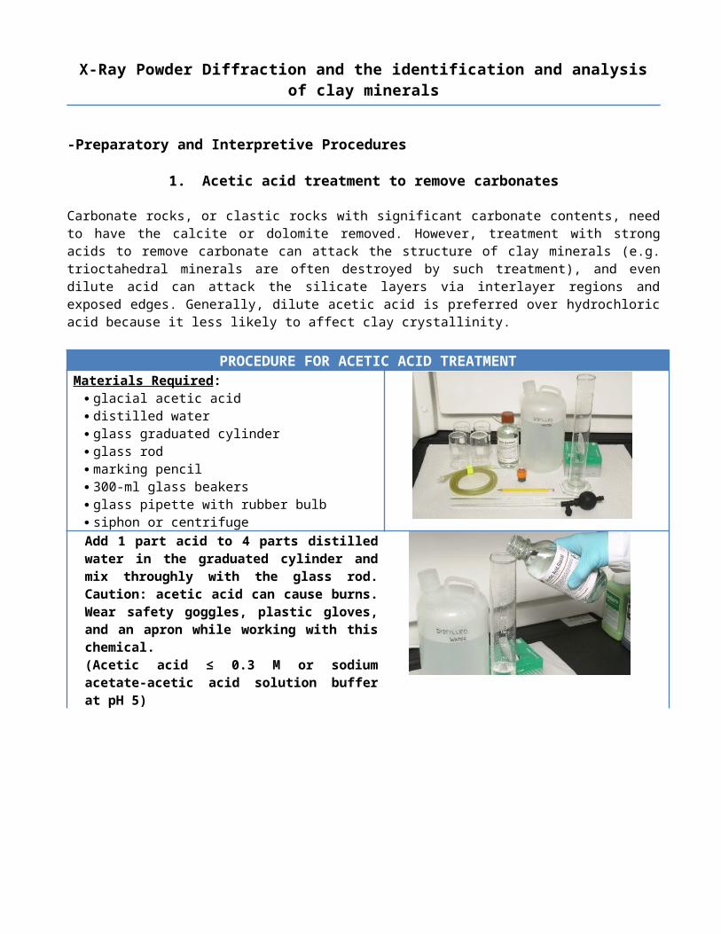
PROCEDURE FOR ACETIC ACID TREATMENTMaterials Required:
glacial acetic acid distilled water glass graduated cylinder glass rod marking pencil 300-ml glass beakers glass pipette with rubber bulb siphon or centrifuge
Add 1 part acid to 4 parts distilled water in the graduated cylinder and mix throughly with the glass rod. Caution: acetic acid can cause burns. Wear safety goggles, plastic gloves, and an apron while working with this chemical.(Acetic acid ≤ 0.3 M or sodium acetate-acetic acid solution buffer at pH 5)
Label 300-ml beakers and add sample.
P á g i n a | 2
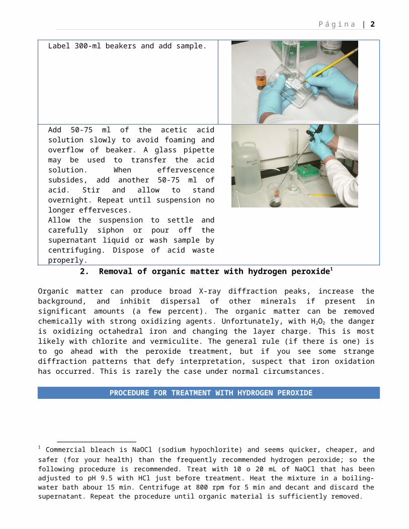
Add 50-75 ml of the acetic acid solution slowly to avoid foaming and overflow of beaker. A glass pipette may be used to transfer the acid solution. When effervescence subsides, add another 50-75 ml of acid. Stir and allow to stand overnight. Repeat until suspension no longer effervesces.Allow the suspension to settle and carefully siphon or pour off the supernatant liquid or wash sample by centrifuging. Dispose of acid waste properly.
2. Removal of organic matter with hydrogen peroxide1
Organic matter can produce broad X-ray diffraction peaks, increase the background, and inhibit dispersal of other minerals if present in significant amounts (a few percent). The organic matter can be removed chemically with strong oxidizing agents. Unfortunately, with H2O2 the danger is oxidizing octahedral iron and changing the layer charge. This is most likely with chlorite and vermiculite. The general rule (if there is one) is to go ahead with the peroxide treatment, but if you see some strange diffraction patterns that defy interpretation, suspect that iron oxidation has occurred. This is rarely the case under normal circumstances.
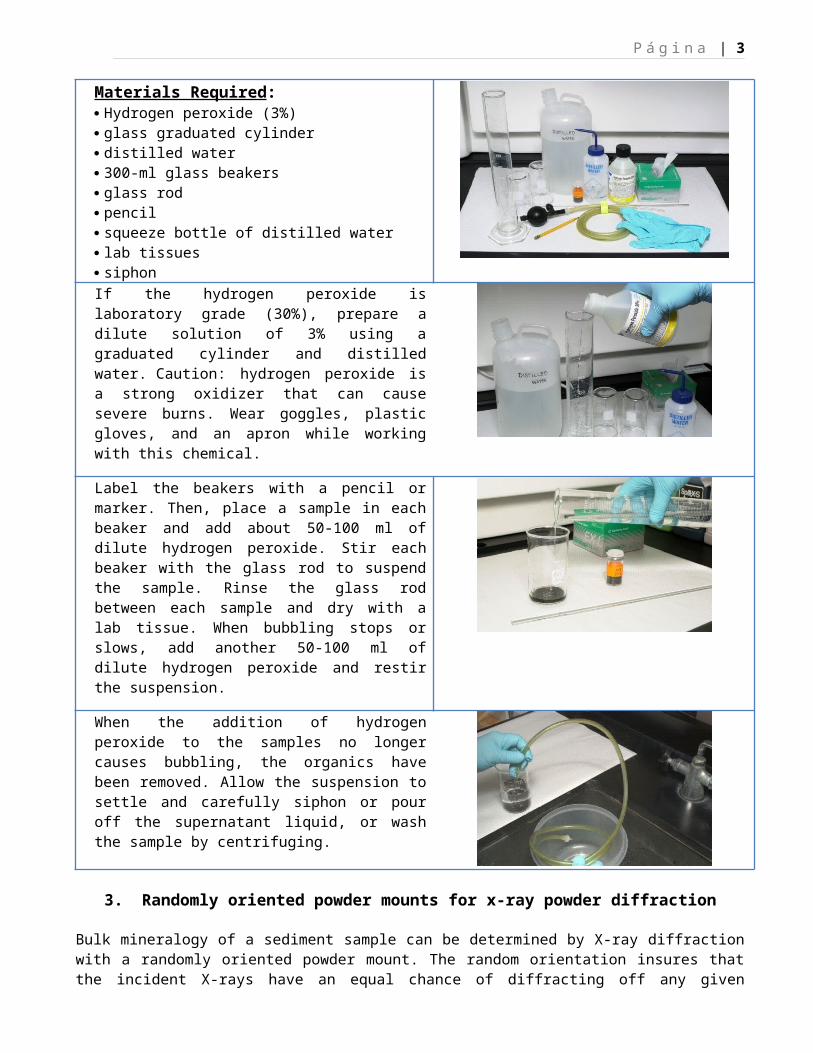
PROCEDURE FOR TREATMENT WITH HYDROGEN PEROXIDEMaterials Required: Hydrogen peroxide (3%) glass graduated cylinder distilled water 300-ml glass beakers glass rod pencil squeeze bottle of distilled water lab tissues siphonIf the hydrogen peroxide is laboratory grade (30%), prepare a dilute solution of 3% using a graduated cylinder and distilled water. Caution: hydrogen peroxide is a strong oxidizer that can cause severe burns. Wear goggles, plastic gloves, and an apron while working with this chemical.
1 Commercial bleach is NaOCl (sodium hypochlorite) and seems quicker, cheaper, and safer (for your health) than the frequently recommended hydrogen peroxide; so the following procedure is recommended. Treat with 10 o 20 mL of NaOCl that has been adjusted to pH 9.5 with HCl just before treatment. Heat the mixture in a boiling-water bath abour 15 min. Centrifuge at 800 rpm for 5 min and decant and discard the supernatant. Repeat the procedure until organic material is sufficiently removed.
P á g i n a | 3
Label the beakers with a pencil or marker. Then, place a sample in each beaker and add about 50-100 ml of dilute hydrogen peroxide. Stir each beaker with the glass rod to suspend the sample. Rinse the glass rod between each sample and dry with a lab tissue. When bubbling stops or slows, add another 50-100 ml of dilute hydrogen peroxide and restir the suspension.
When the addition of hydrogen peroxide to the samples no longer causes bubbling, the organics have been removed. Allow the suspension to settle and carefully siphon or pour off the supernatant liquid, or wash the sample by centrifuging.
3. Randomly oriented powder mounts for x-ray powder diffraction
Bulk mineralogy of a sediment sample can be determined by X-ray diffraction with a randomly oriented powder mount. The random orientation insures that the incident X-rays have an equal chance of diffracting off any given crystal lattice face of the minerals in the sample. The use of a powder press to make randomly oriented powder mounts is undesirable because excessive force could cause preferred orientation of the crystallites. Although some orientation is inevitable (platy minerals tend toward some preferred orientation), the method described below is sufficient for most applications.Sample splits are commonly dried at 60 °C prior to the preparation of randomly oriented powder mounts. The mounts are typically X-rayed between the angles of 2 and 70 degrees two theta using copper Kα radiation at a scanning rate of 2 degrees per minute.
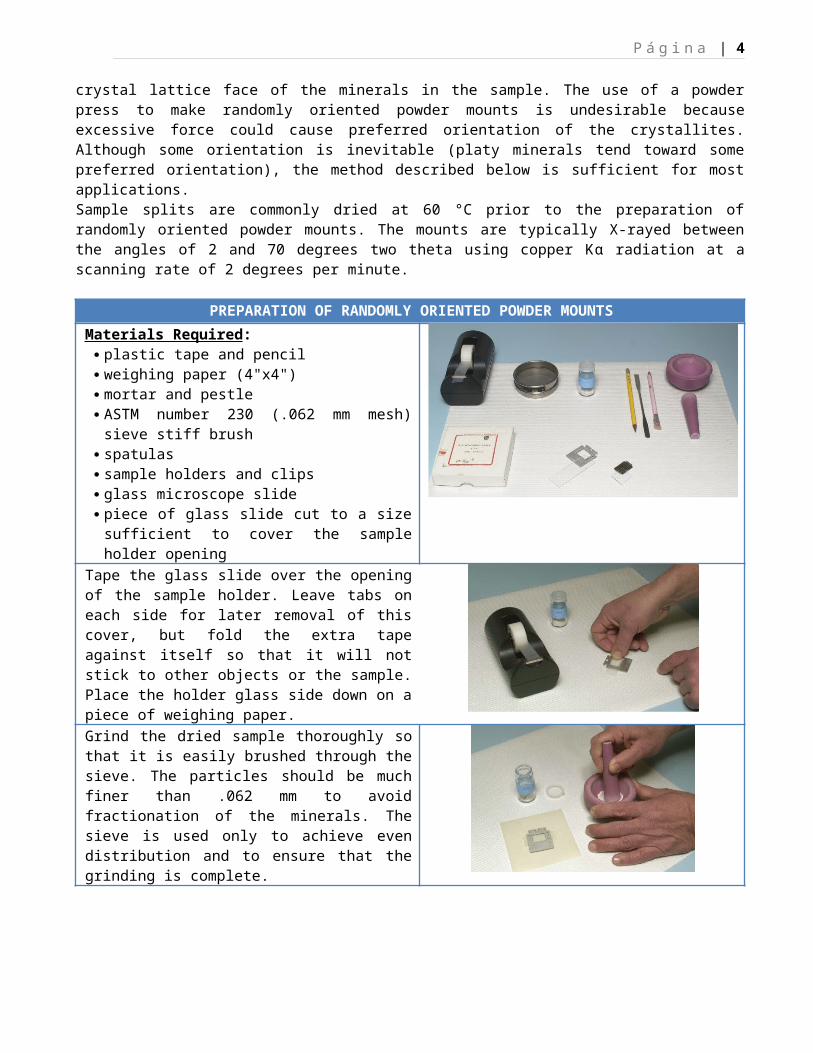
PREPARATION OF RANDOMLY ORIENTED POWDER MOUNTSMaterials Required: plastic tape and pencil weighing paper (4"x4") mortar and pestle ASTM number 230 (.062 mm mesh) sieve stiff brush spatulas sample holders and clips glass microscope slide piece of glass slide cut to a size sufficient to cover
the sample holder openingTape the glass slide over the opening of the sample holder. Leave tabs on each side for later removal of this cover, but fold the extra tape against itself so that it will not stick to other objects or the sample. Place the holder glass side down on a piece of weighing paper.
P á g i n a | 4
Grind the dried sample thoroughly so that it is easily brushed through the sieve. The particles should be much finer than .062 mm to avoid fractionation of the minerals. The sieve is used only to achieve even distribution and to ensure that the grinding is complete.
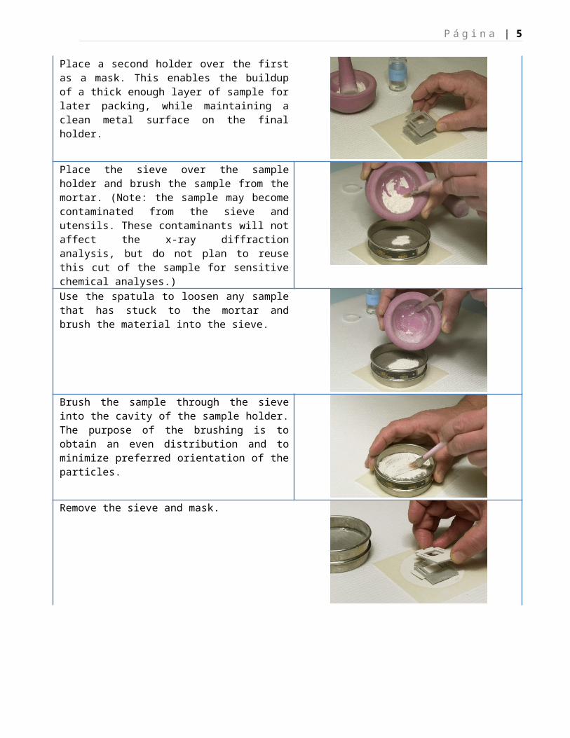
Place a second holder over the first as a mask. This enables the buildup of a thick enough layer of sample for later packing, while maintaining a clean metal surface on the final holder.
Place the sieve over the sample holder and brush the sample from the mortar. (Note: the sample may become contaminated from the sieve and utensils. These contaminants will not affect the x-ray diffraction analysis, but do not plan to reuse this cut of the sample for sensitive chemical analyses.)
Use the spatula to loosen any sample that has stuck to the mortar and brush the material into the sieve.
Brush the sample through the sieve into the cavity of the sample holder. The purpose of the brushing is to obtain an even distribution and to minimize preferred orientation of the particles.
Remove the sieve and mask.
P á g i n a | 5
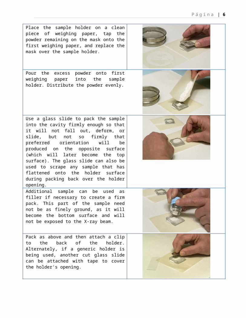
Place the sample holder on a clean piece of weighing paper, tap the powder remaining on the mask onto the first weighing paper, and replace the mask over the sample holder.
Pour the excess powder onto first weighing paper into the sample holder. Distribute the powder evenly.
Use a glass slide to pack the sample into the cavity firmly enough so that it will not fall out, deform, or slide, but not so firmly that preferred orientation will be produced on the opposite surface (which will later become the top surface). The glass slide can also be used to scrape any sample that has flattened onto the holder surface during packing back over the holder opening.
Additional sample can be used as filler if necessary to create a firm pack. This part of the sample need not be as finely ground, as it will become the bottom surface and will not be exposed to the X-ray beam.
Pack as above and then attach a clip to the back of the holder. Alternately, if a generic holder is being used, another cut glass slide can be attached with tape to cover the holder's opening.
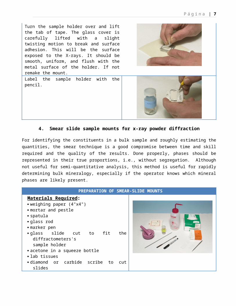
Turn the sample holder over and lift the tab of tape. The glass cover is carefully lifted with a slight twisting motion to break and surface adhesion. This will be the surface exposed to the X-rays. It should be smooth, uniform, and flush with the metal surface of the holder. If not remake the mount.
P á g i n a | 6
Label the sample holder with the pencil.
4. Smear slide sample mounts for x-ray powder diffraction
For identifying the constituents in a bulk sample and roughly estimating the quantities, the smear technique is a good compromise between time and skill required and the quality of the results. Done properly, phases should be represented in their true proportions, i.e., without segregation. Although not useful for semi-quantitative analysis, this method is useful for rapidly determining bulk mineralogy, especially if the operator knows which mineral phases are likely present.
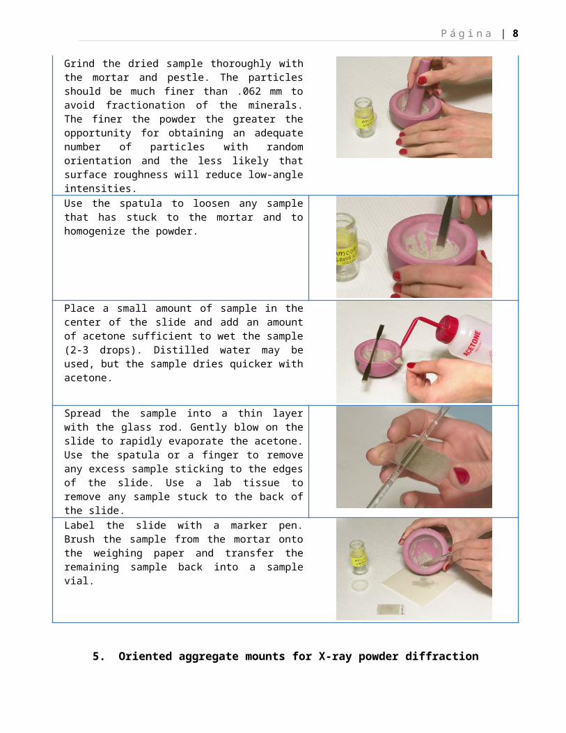
PREPARATION OF SMEAR-SLIDE MOUNTSMaterials Required: weighing paper (4"x4") mortar and pestle spatula glass rod marker pen glass slide cut to fit the diffractometers's
sample holder acetone in a squeeze bottle lab tissues diamond or carbide scribe to cut slidesGrind the dried sample thoroughly with the mortar and pestle. The particles should be much finer than .062 mm to avoid fractionation of the minerals. The finer the powder the greater the opportunity for obtaining an adequate number of particles with random orientation and the less likely that surface roughness will reduce low-angle intensities.
Use the spatula to loosen any sample that has stuck to the mortar and to homogenize the powder.
P á g i n a | 7
Place a small amount of sample in the center of the slide and add an amount of acetone sufficient to wet the sample (2-3 drops). Distilled water may be used, but the sample dries quicker with acetone.
Spread the sample into a thin layer with the glass rod. Gently blow on the slide to rapidly evaporate the acetone. Use the spatula or a finger to remove any excess sample sticking to the edges of the slide. Use a lab tissue to remove any sample stuck to the back of the slide.
Label the slide with a marker pen. Brush the sample from the mortar onto the weighing paper and transfer the remaining sample back into a sample vial.
5. Oriented aggregate mounts for X-ray powder diffraction
The clay fraction can be separated from the bulk sample by centrifugation or decantation and mounted as an oriented aggregate mount for clay-mineral identification. The oriented aggregate mounts force the clay mineral particles, usually plate-shaped phyllosilicates, to lie flat, allowing the operator to direct the incident X-ray beam down the z axis of the minerals and to record the diagnostic basal diffractions. It is the z axis that shows the extent of d-spacing expansion and (or) contraction indicative of certain clay minerals during subsequent treatments. These treatments include: air drying, glycolation with ethylene glycol, heating to 400 °C, and heating to 550 °C. The material from the randomly oriented powder mount may be used for this analysis.
Commonly used substrates for oriented aggregate mounts include silver filters, ceramic tiles, and glass slides. Silver filters tend to be expensive and react with chloride ions to form crystalline compounds that change the mass-absorption coefficient of the mount and affect peak intensities; ceramic tiles tend to contain crystalline material that may complicate the diffraction pattern. Glass slides cut to fit the sample holder of a diffractometer are used in the filter-peel method described below.
PREPARATION OF ORIENTED AGGREGATE MOUNTS USING THE FILTER-PEEL TECHNIQUE
P á g i n a | 8
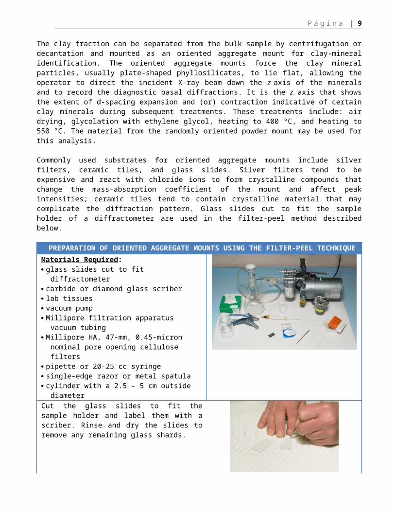
Materials Required: glass slides cut to fit diffractometer carbide or diamond glass scriber lab tissues vacuum pump Millipore filtration apparatus vacuum tubing Millipore HA, 47-mm, 0.45-micron
nominal pore opening cellulose filters pipette or 20-25 cc syringe single-edge razor or metal spatula cylinder with a 2.5 - 5 cm outside diameterCut the glass slides to fit the sample holder and label them with a scriber. Rinse and dry the slides to remove any remaining glass shards.
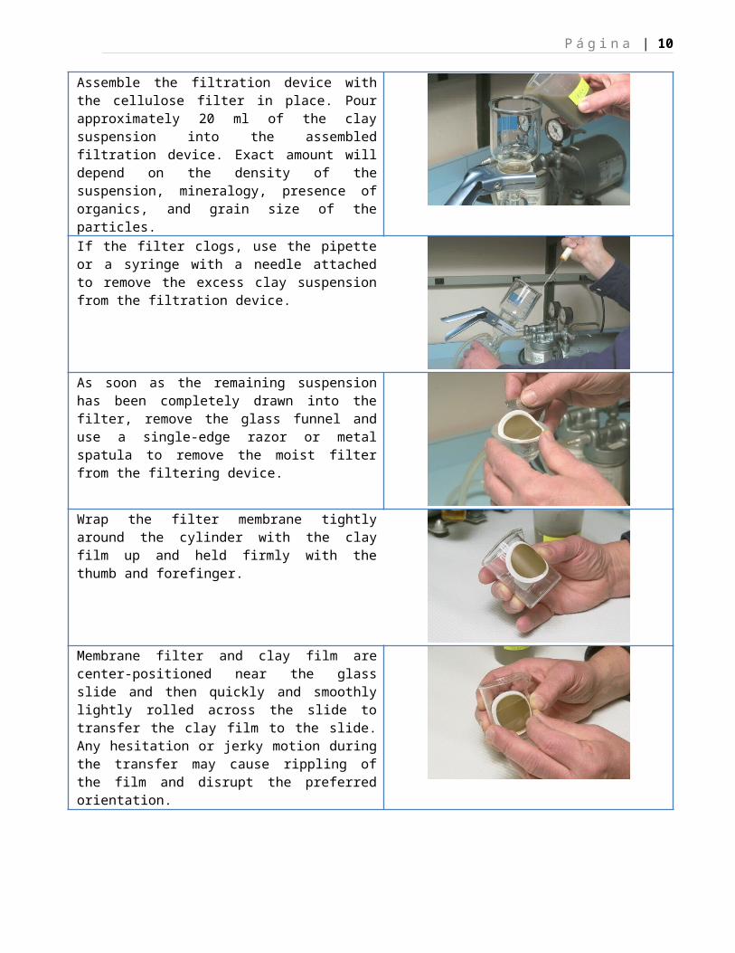
Assemble the filtration device with the cellulose filter in place. Pour approximately 20 ml of the clay suspension into the assembled filtration device. Exact amount will depend on the density of the suspension, mineralogy, presence of organics, and grain size of the particles.
If the filter clogs, use the pipette or a syringe with a needle attached to remove the excess clay suspension from the filtration device.
As soon as the remaining suspension has been completely drawn into the filter, remove the glass funnel and use a single-edge razor or metal spatula to remove the moist filter from the filtering device.
P á g i n a | 9
Wrap the filter membrane tightly around the cylinder with the clay film up and held firmly with the thumb and forefinger.
Membrane filter and clay film are center-positioned near the glass slide and then quickly and smoothly lightly rolled across the slide to transfer the clay film to the slide. Any hesitation or jerky motion during the transfer may cause rippling of the film and disrupt the preferred orientation.
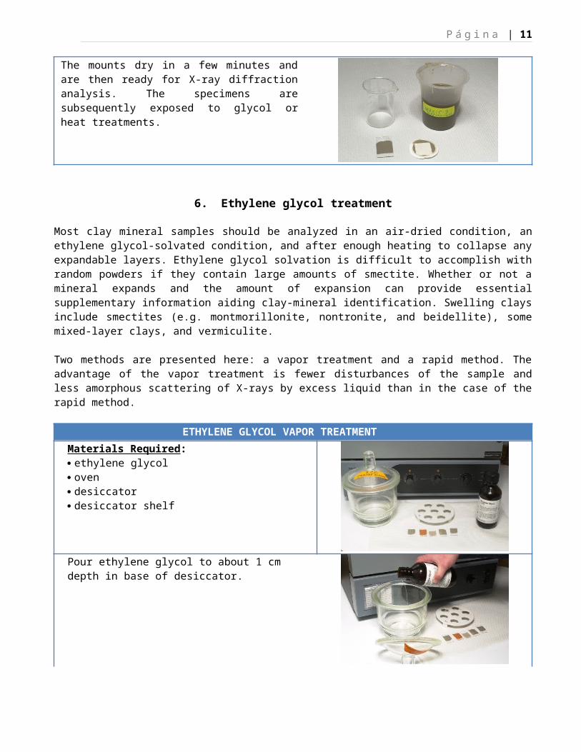
The mounts dry in a few minutes and are then ready for X-ray diffraction analysis. The specimens are subsequently exposed to glycol or heat treatments.
6. Ethylene glycol treatment
Most clay mineral samples should be analyzed in an air-dried condition, an ethylene glycol-solvated condition, and after enough heating to collapse any expandable layers. Ethylene glycol solvation is difficult to accomplish with random powders if they contain large amounts of smectite. Whether or not a mineral expands and the amount of expansion can provide essential supplementary information aiding clay-mineral identification. Swelling clays include smectites (e.g. montmorillonite, nontronite, and beidellite), some mixed-layer clays, and vermiculite.
Two methods are presented here: a vapor treatment and a rapid method. The advantage of the vapor treatment is fewer disturbances of the sample and less amorphous scattering of X-rays by excess liquid than in the case of the rapid method.
ETHYLENE GLYCOL VAPOR TREATMENTMaterials Required: ethylene glycol oven desiccator desiccator shelf
P á g i n a | 10
Pour ethylene glycol to about 1 cm depth in base of desiccator.
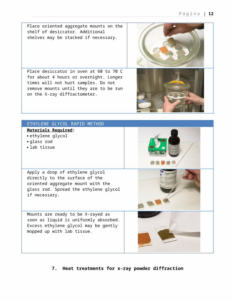
Place oriented aggregate mounts on the shelf of desiccator. Additional shelves may be stacked if necessary.
Place desiccator in oven at 60 to 70 C for about 4 hours or overnight. Longer times will not hurt samples. Do not remove mounts until they are to be run on the X-ray diffractometer.
ETHYLENE GLYCOL RAPID METHODMaterials Required: ethylene glycol glass rod lab tissue
Apply a drop of ethylene glycol directly to the surface of the oriented aggregate mount with the glass rod. Spread the ethylene glycol if necessary.
P á g i n a | 11
Mounts are ready to be X-rayed as soon as liquid is uniformly absorbed. Excess ethylene glycol may be gently mopped up with lab tissue.
7. Heat treatments for x-ray powder diffraction
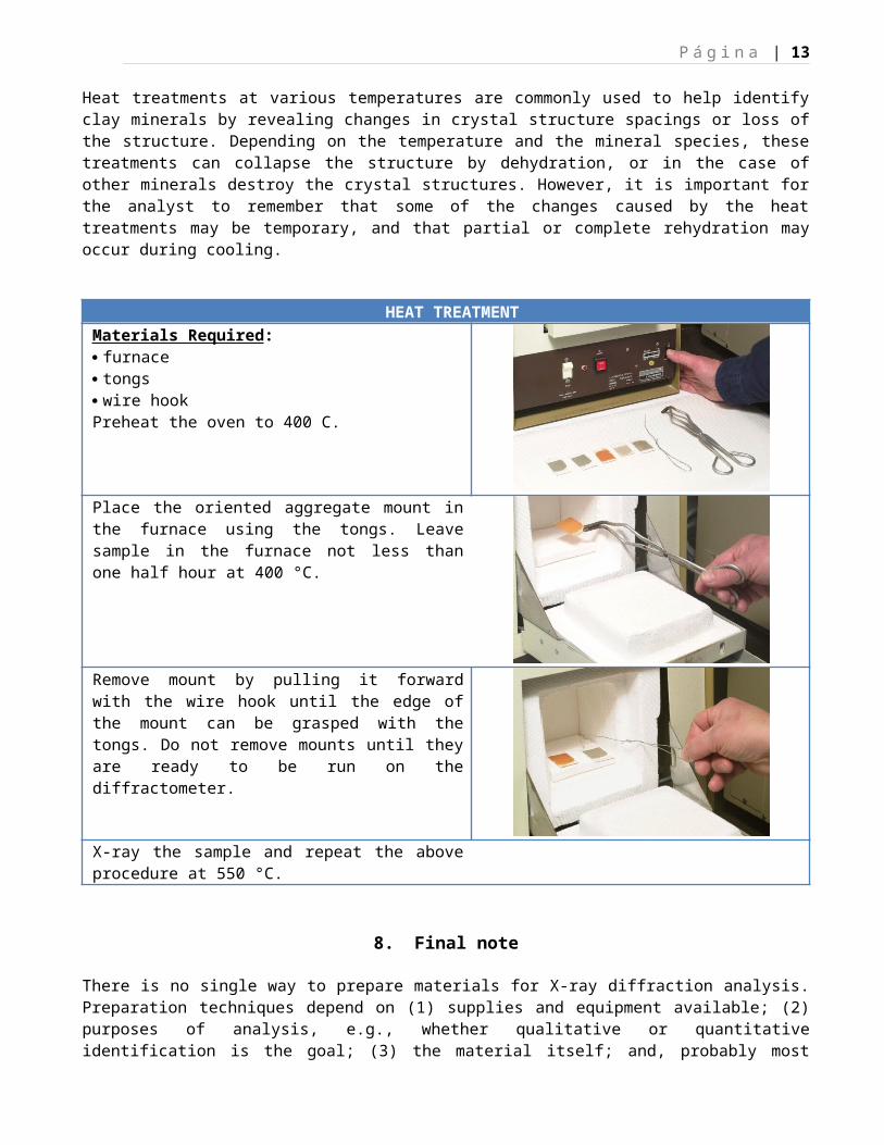
Heat treatments at various temperatures are commonly used to help identify clay minerals by revealing changes in crystal structure spacings or loss of the structure. Depending on the temperature and the mineral species, these treatments can collapse the structure by dehydration, or in the case of other minerals destroy the crystal structures. However, it is important for the analyst to remember that some of the changes caused by the heat treatments may be temporary, and that partial or complete rehydration may occur during cooling.
HEAT TREATMENTMaterials Required: furnace tongs wire hookPreheat the oven to 400 C.
Place the oriented aggregate mount in the furnace using the tongs. Leave sample in the furnace not less than one half hour at 400 °C.
Remove mount by pulling it forward with the wire hook until the edge of the mount can be grasped with the tongs. Do not remove mounts until they are ready to be run on the diffractometer.
X-ray the sample and repeat the above procedure at 550 °C.
P á g i n a | 12
8. Final note
There is no single way to prepare materials for X-ray diffraction analysis. Preparation techniques depend on (1) supplies and equipment available; (2) purposes of analysis, e.g., whether qualitative or quantitative identification is the goal; (3) the material itself; and, probably most important, (4) your sense of organization and habits, your goals and your understanding of the principles of X-ray diffraction.
Finally, when you write a report or submit a paper for publication, include the X-ray diffraction tracings in the form in which they came off of the diffractometer, not after they have been smoothed by a draftsperson. Such traces are data that can be reinterpreted in the future as more is learned about peak shapes, relative intensities, and other, as yet unrecognized features.
P á g i n a | 13
9. Clay Mineral Identification Flow Diagram
X-Rays of Oriented Aggregates
Treated with Electron Micrograph X-rays of randomlyAir Dried ethylene glycol Heated to 400o C Heated to 550o C if required oriented powders RESULT
~29Å Expands to 31-32Å with May disappear or give 24Å spacing. Increase in intensity of 24Å spacing Regularly interstratifiedrational sequence of chlorite-montmorillonite orhigher orders cholorite-vermiculite (corrensite)
Expands but gives irrational sequence. May give irrational sequence. May give irrational sequences. May show Randomly interstratifiedPeaks may be broad. increase in intensity of 12-14Å peak chlorite-montmorillonite
~14Å No change No change Increase in intensity 060 near 1.54Å Chlorite060 near 1.50Å Dioctahedral chlorite
No change or slight increase Collapses to ~10Å No change or slight additional collapse 060 near 1.54Å VermiculiteSlight collapse ~12Å Additional collapse ~11Å 060 near 1.50Å Dioctahedral vermiculite
Expands to 17Å Collapses to ~10Å No change or slight additional collapse 060 near 1.50Å MontmorilloniteCollapses to ~10Å with No change or slight additional collapse 060 near 1.52Å Nontronitevery weak 5Å peak 060 near 1.54Å Trioctahedral montmorillonite
or vermiculite
>10 - 14Å No change - rational sequence Collapses to ~10Å Collapses to 10Å 060 near 1.54Å Regularly interstratifiedof higher orders illite-vermiculite
No change No change or slight increase in intensity 060 near 1.54Å Regularly interstratifiedillite-chlorite
No change - irrational sequence Collapses to ~10Å Collapses to 10Å 060 near 1.54Å Randomly interstratifiedillite-vermiculite
No change No change or slight increase in intensity 060 near 1.54Å Randomly interstratifiedillite-chlorite
Expands to higher spacing Collapses to ~10Å Collapses to 10Å 060 near 1.50Å Interstratifiedillite-montmorillonite
060 near 1.54Å Interstratified trioctahedralillite-montmorillonite
No change Slight collapse Further collapse 060 near 1.50Å Interstratified dioctahedralillite-vermiculite
12 - 12.5Å No change Destroyed or reduced in intensity Destroyed Fibrous morphology Check hkl's against standard Sepiolite
10.5Å No change Destroyed - - may survive slightly Destroyed Fibrous morphology Check hkl's against standard Palygorskitelower temperature
~10Å Symmetrical - no change No change No change 060 near 1.50Å; Illite (and/or mica),check hkl's against muscovitic,standards for polymorphs various polymorphs060 between 1.51Å - 1.52Å Glauconite or celadonite5Å peak very weak (Roscoelite if V bearing)060 near 1.54Å Bictite, various polymorphs
Unsymmetrical or slight shift either way No change or slight sharpening 060 variable Interstratified illite-montmorilloniteor illite-vermiculite
Expands to ~11Å Collapses to ~7Å Destroyed Tubular morphology 060 near 1.49Å Endellite
7Å Increases in spacing or no change Collapses to 7Å Destroyed Tubular morphology 060 near 1.49Å; Halloysitehk bands present
No change No change No change Fibrous morphology Check hkl's against standard ChrysotilePlaty morphology Check hkl's against standard Antigorite
Destroyed Platy morphology 060 near 1.49Å; Disordered kaolinitehk bands present; (fireclay)moderately broad 001's060 near 1.54Å Chlorite
(Check increase in intensityof 14Å spacing)
060 near 1.50Å Dioctahedral chlorite(Check increase in intensity
of 14Å spacing)Hexagonal morphology hkl's resolved Kaolinite
DickiteNacrite
(Check against standard patterns)


![Arcillas - [DePa] Departamento de Programas Audiovisualesdepa.fquim.unam.mx/amyd/archivero/Arcillas_23764.pdf · Universidad Nacional Autónoma de México Facultad de Química Arcillas](https://cdn.vdocuments.mx/doc/165x107/5e1200a9c6aae341fe1ff8ec/arcillas-depa-departamento-de-programas-universidad-nacional-autnoma-de-mxico.jpg)


