I-210 Interchange at Cove Lane A Geotechnical Perspective
Larry D. Sant, PE
Associate & Geotechnical Engineer
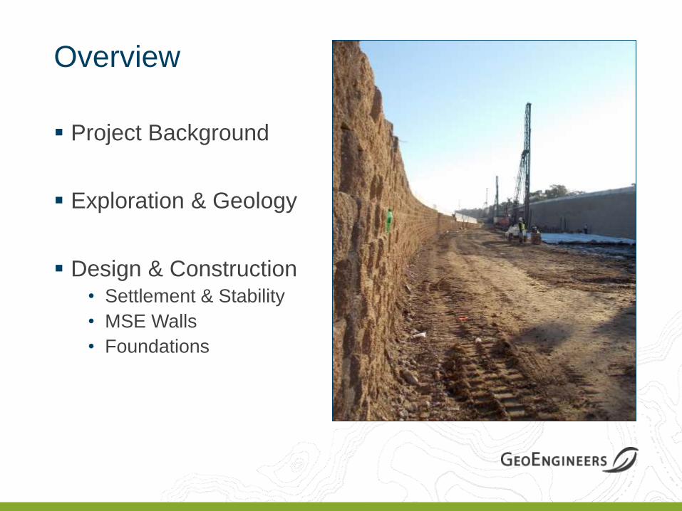
Overview
Project Background
Exploration & Geology
Design & Construction • Settlement & Stability
• MSE Walls
• Foundations
Project Background
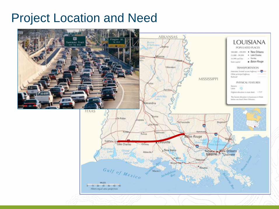
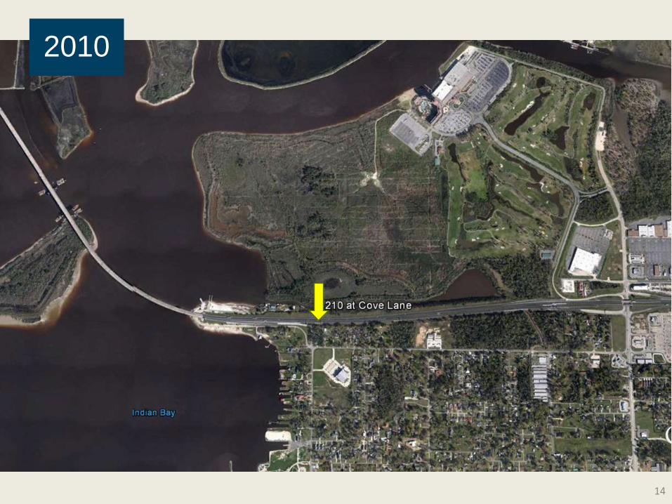
Project Location and Need
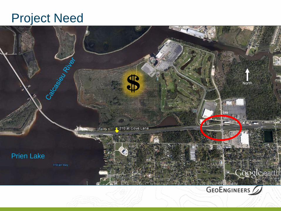
North $
Project Need
Prien Lake
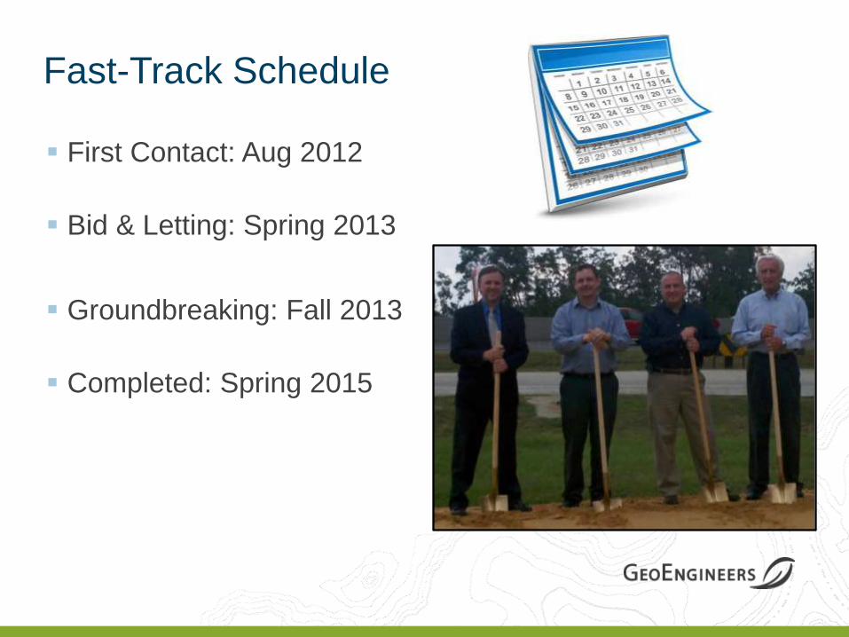
Fast-Track Schedule
First Contact: Aug 2012
Bid & Letting: Spring 2013
Groundbreaking: Fall 2013
Completed: Spring 2015
7
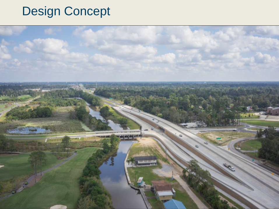
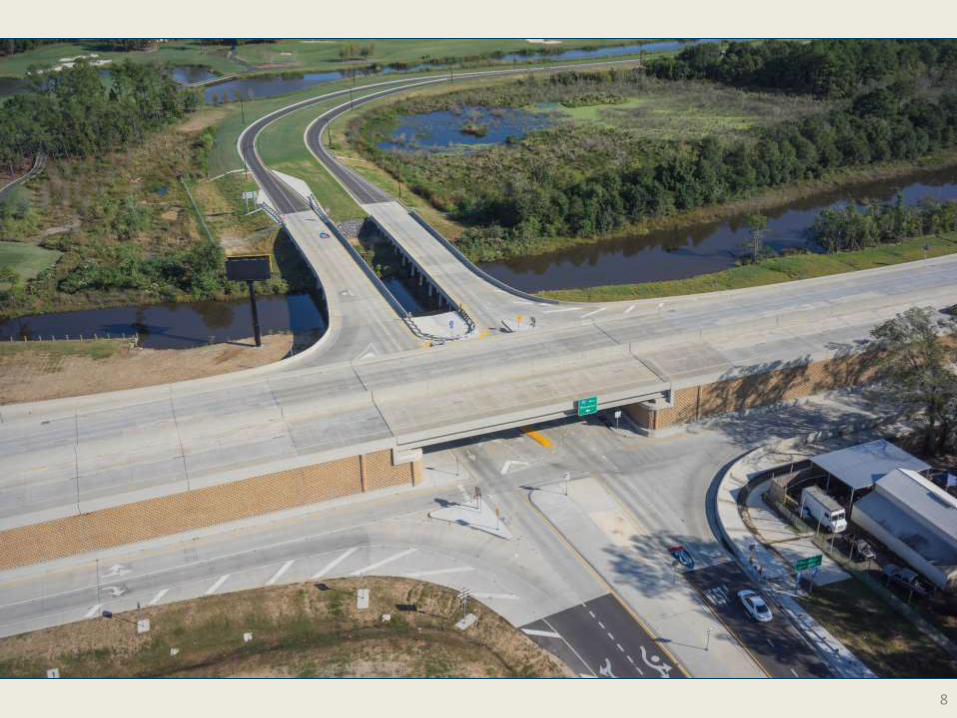
Design Concept
8

Exploration and Geology
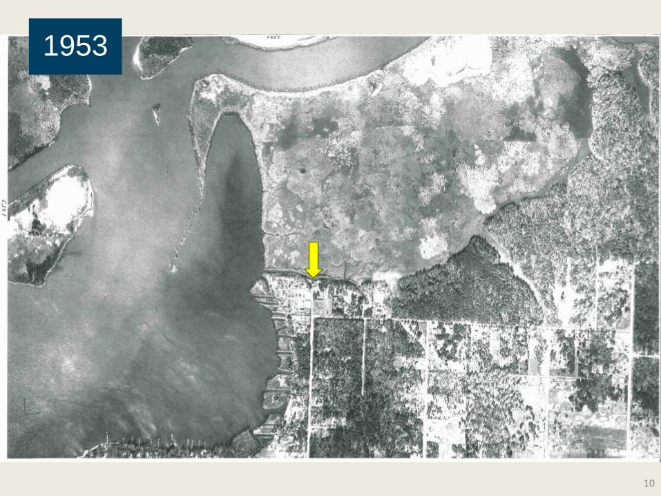
10
1953
11
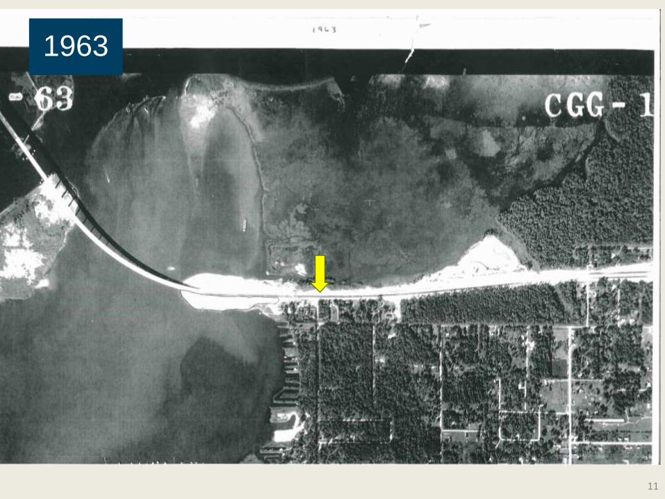
1963
12
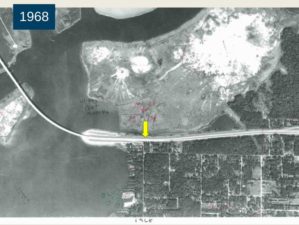
1968
13
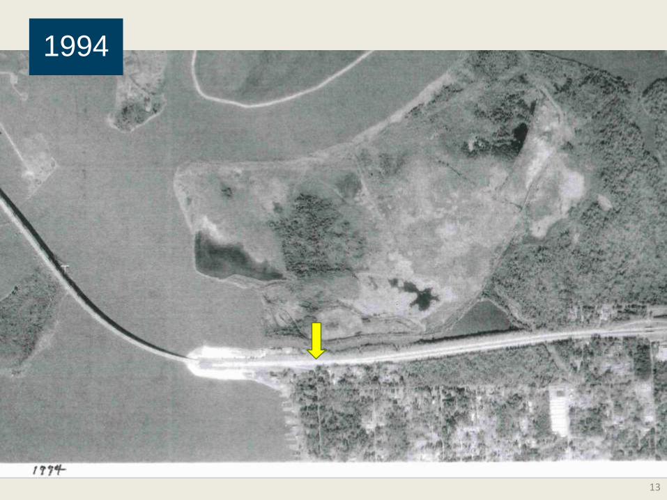
1994
14
2010
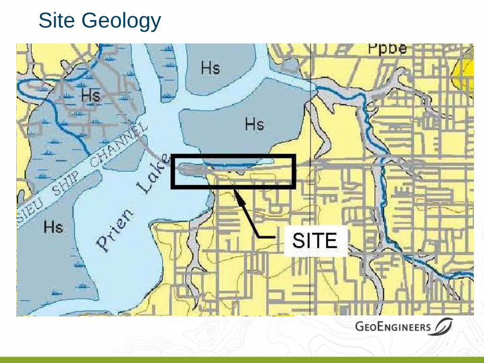
Site Geology
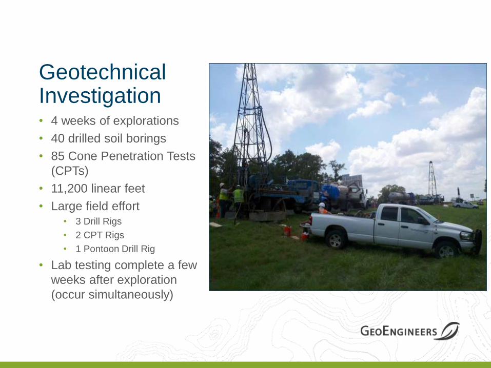
Geotechnical Investigation • 4 weeks of explorations
• 40 drilled soil borings
• 85 Cone Penetration Tests
(CPTs)
• 11,200 linear feet
• Large field effort • 3 Drill Rigs
• 2 CPT Rigs
• 1 Pontoon Drill Rig
• Lab testing complete a few
weeks after exploration
(occur simultaneously)
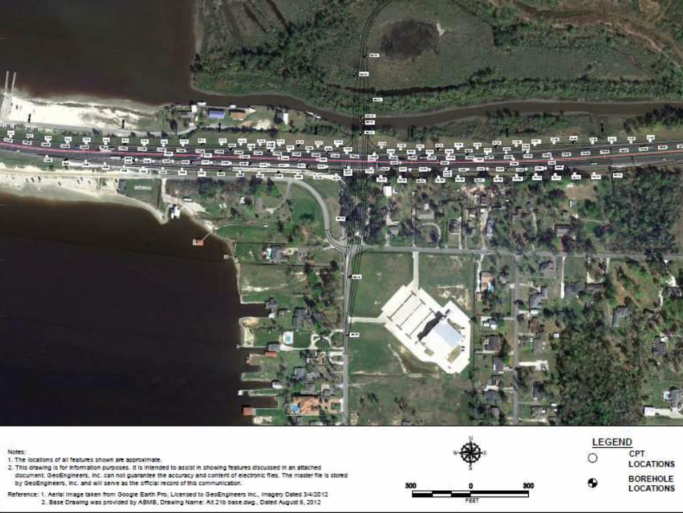
Subsurface Explorations
0.5 Miles
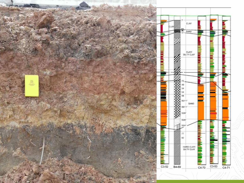

Subsurface Profile
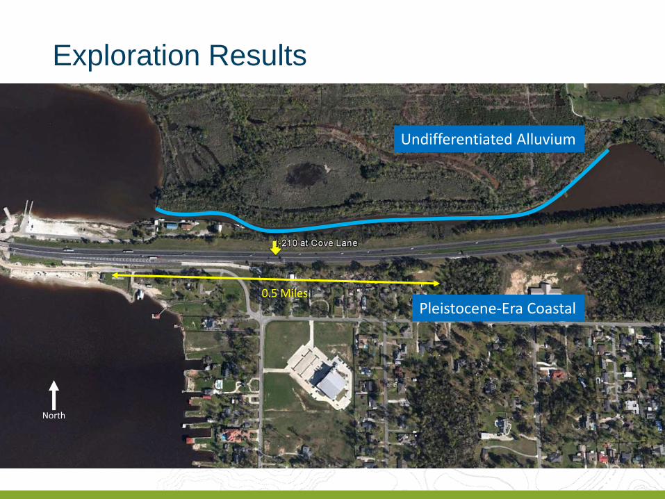
Undifferentiated Alluvium
Pleistocene-Era Coastal
North
0.5 Miles
Exploration Results
Design and Construction Overview
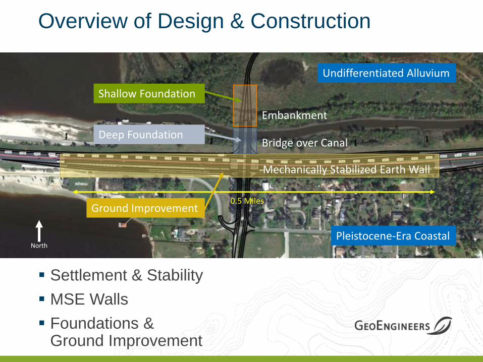
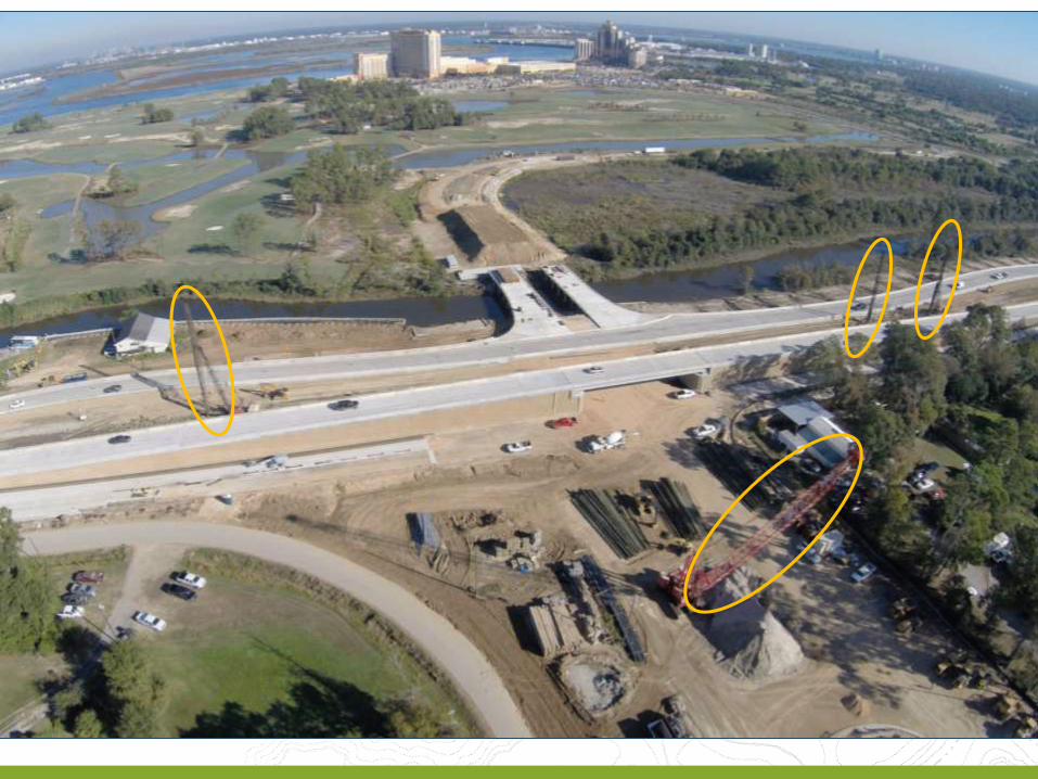
Overview of Design & Construction
North
0.5 Miles
Embankment
Bridge over Canal
Mechanically Stabilized Earth Wall
Undifferentiated Alluvium
Pleistocene-Era Coastal
Shallow Foundation
Deep Foundation
Ground Improvement
Settlement & Stability
MSE Walls
Foundations & Ground Improvement
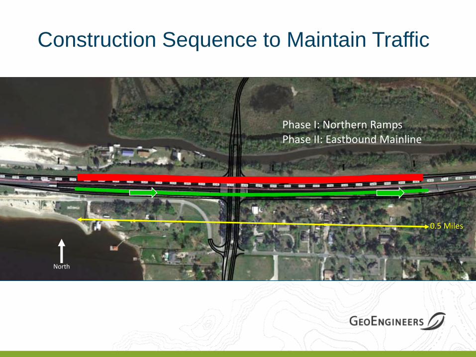
Construction Sequence to Maintain Traffic
North
0.5 Miles
Phase I: Northern Ramps Phase II: Eastbound Mainline
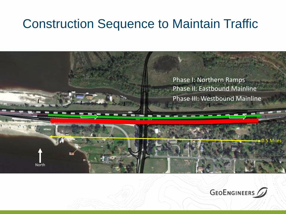
Construction Sequence to Maintain Traffic
North
0.5 Miles
Phase I: Northern Ramps Phase II: Eastbound Mainline
Phase III: Westbound Mainline
Design and Construction Settlement and Stability
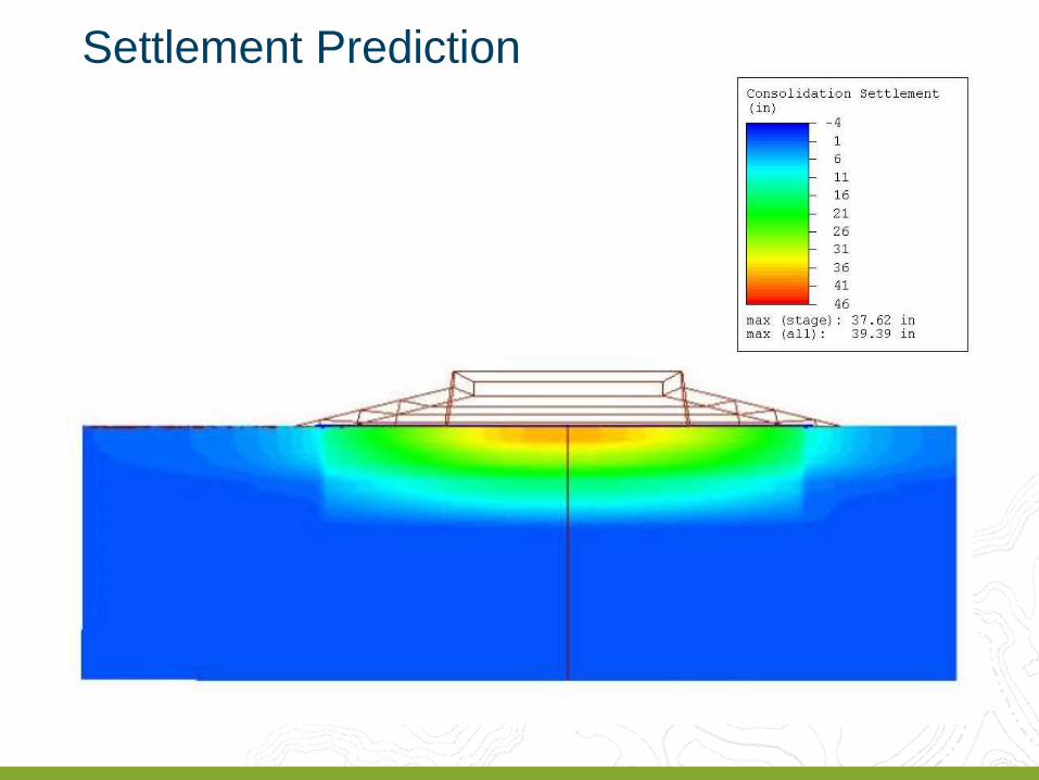
Settlement Prediction
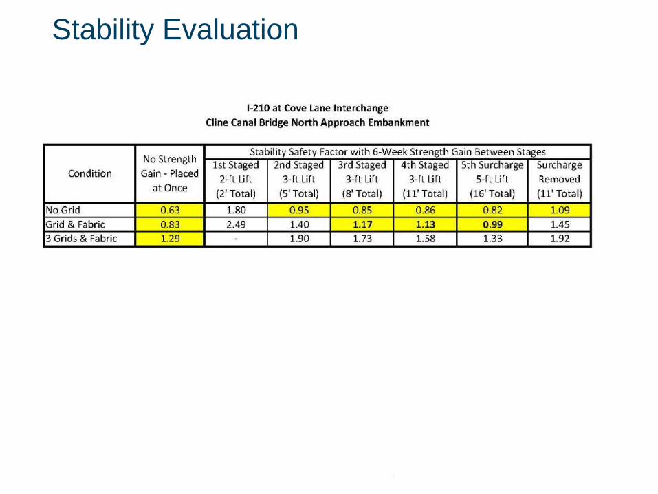
Stability Evaluation
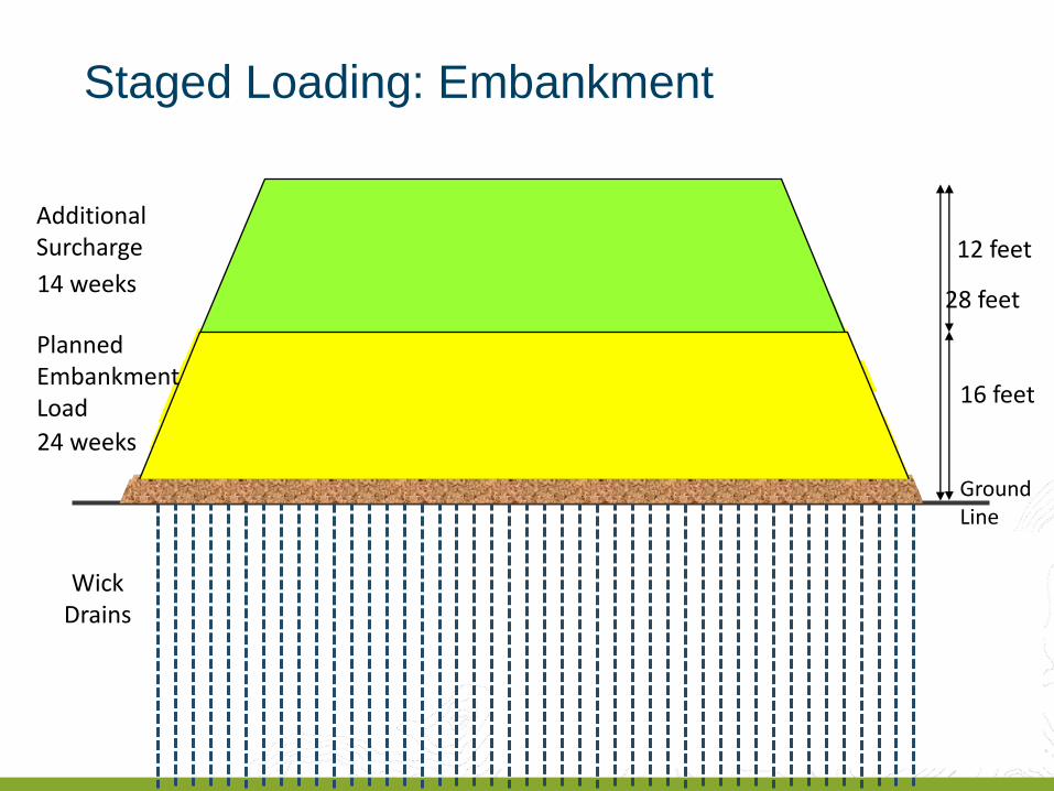
Ground Line
Planned Embankment Load
Additional Surcharge
Wick Drains
28 feet
12 feet
16 feet
24 weeks
14 weeks
Staged Loading: Embankment
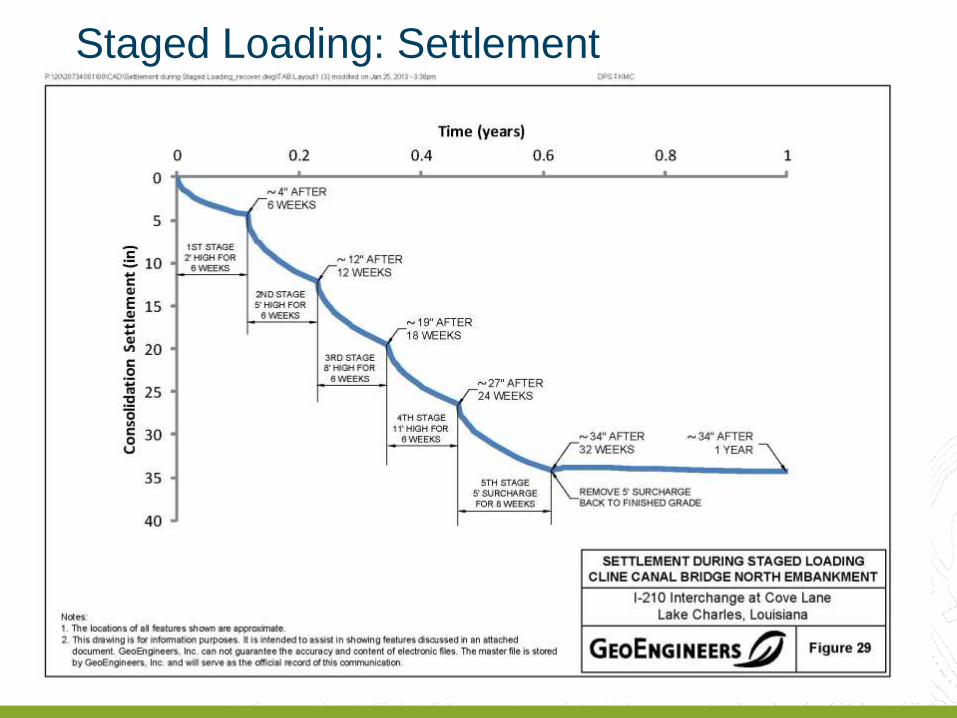
Staged Loading: Settlement

30
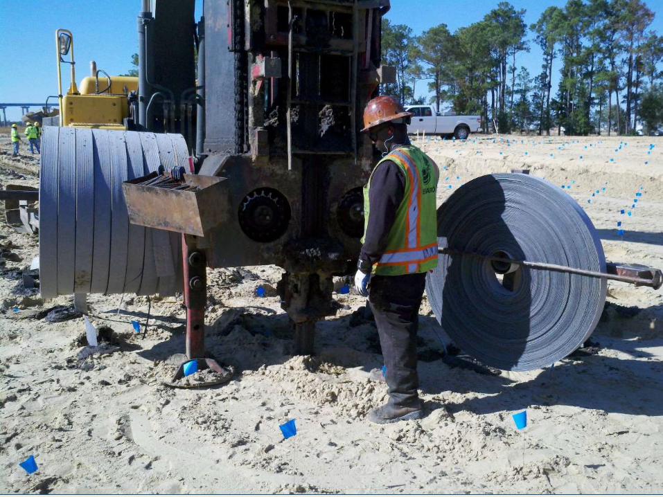
Wick Drain Installation
31
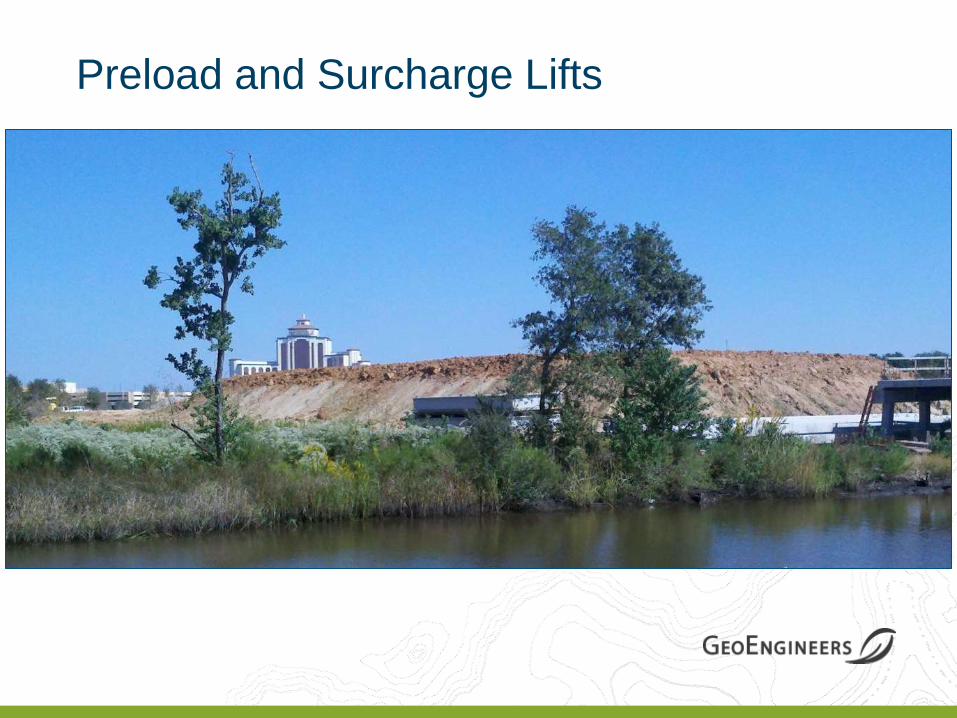
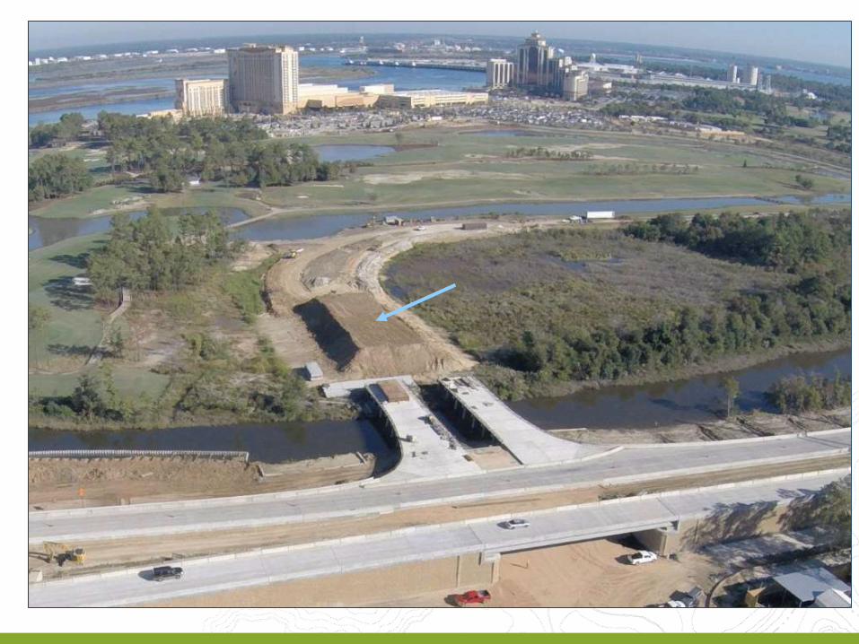
Preload and Surcharge Lifts
Areas of Project Design

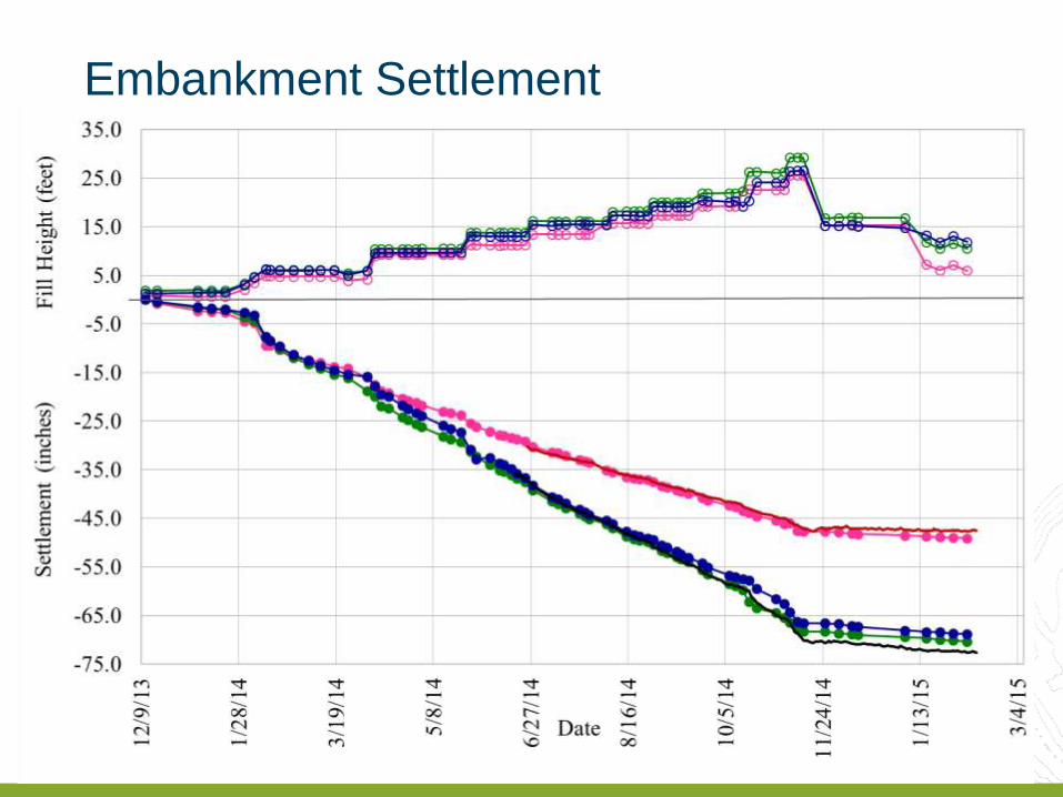
Embankment Settlement
Design and Construction MSE Walls
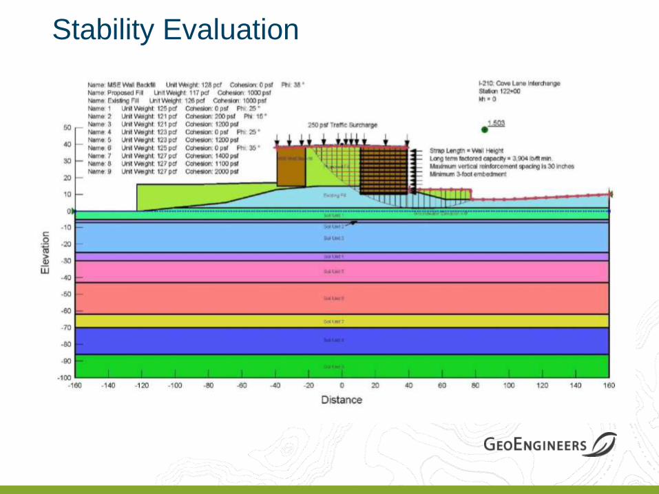
Stability Evaluation

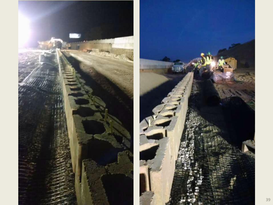
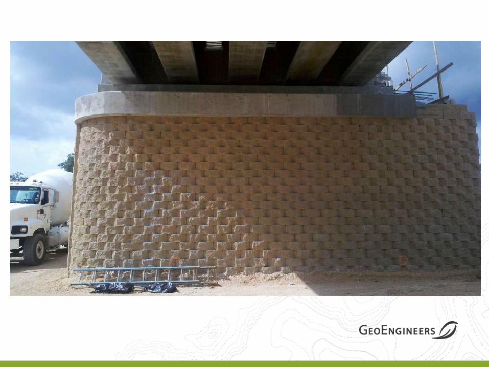
MSE Wall Construction
39
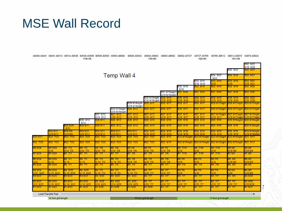
MSE Wall Record
Design and Construction Foundations and Ground Improvement
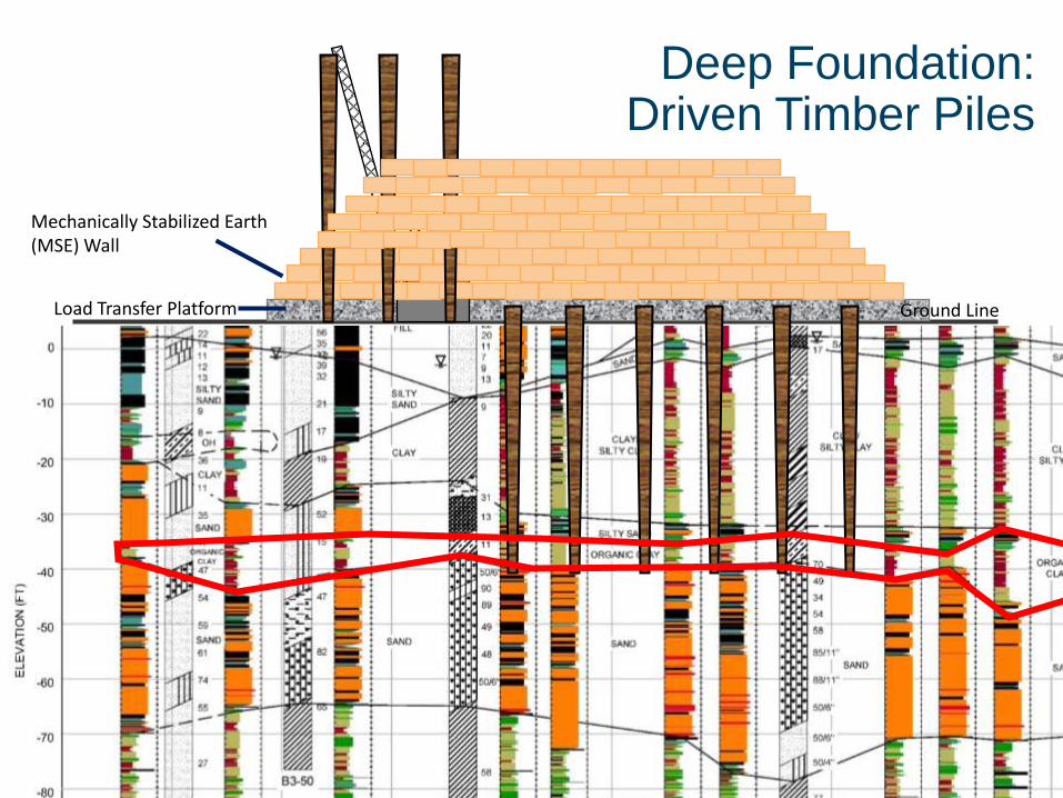
Load Transfer Platform
Mechanically Stabilized Earth (MSE) Wall
Ground Line
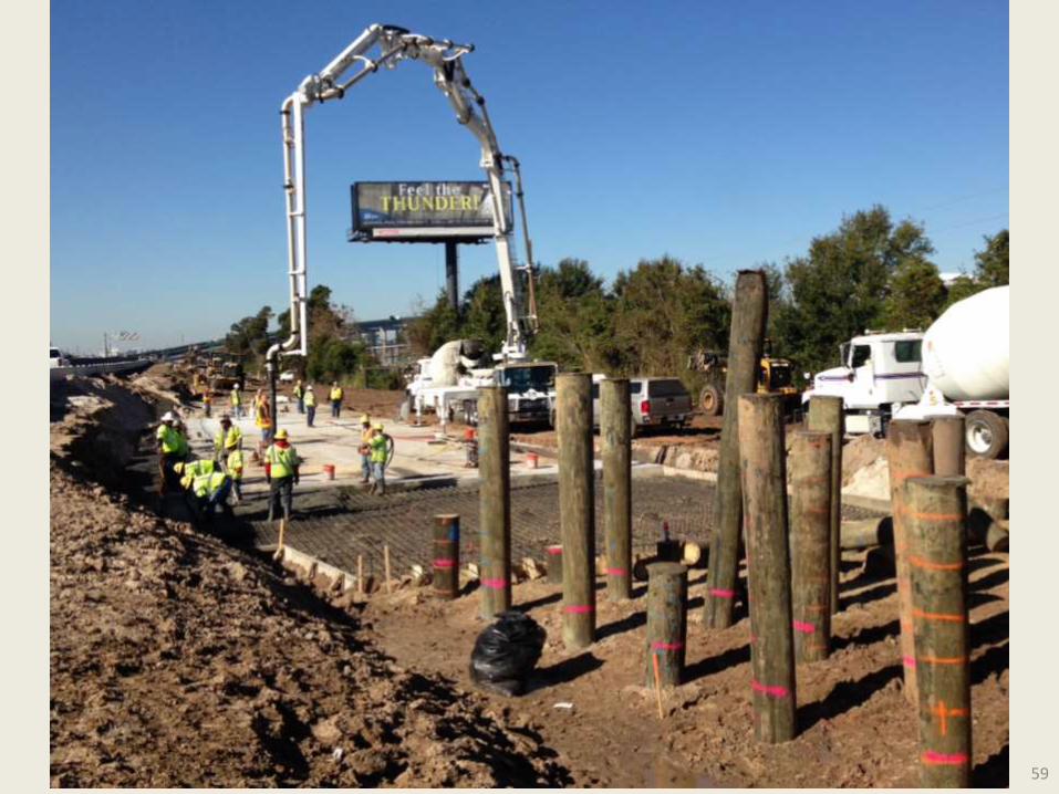
Deep Foundation: Driven Timber Piles
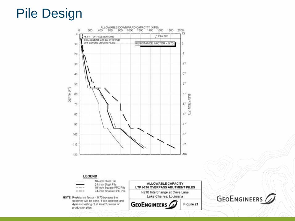
Pile Design
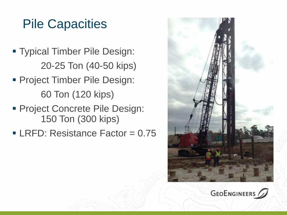
Pile Capacities
Typical Timber Pile Design:
20-25 Ton (40-50 kips)
Project Timber Pile Design:
60 Ton (120 kips)
Project Concrete Pile Design: 150 Ton (300 kips)
LRFD: Resistance Factor = 0.75
Deep Foundation: Driven Piles

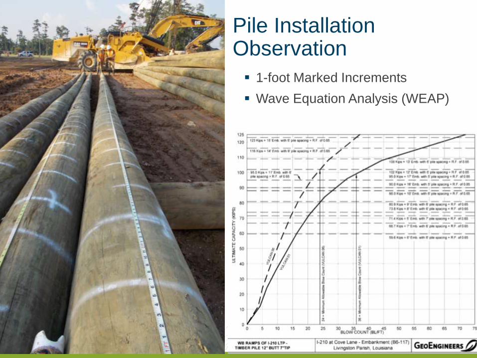
1-foot Marked Increments
Wave Equation Analysis (WEAP)
Pile Installation Observation
49
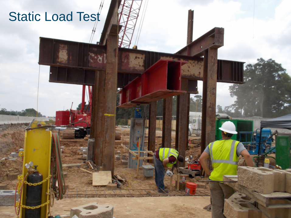
Static Load Tests
3*Design Load
LA DOTD and ASTM Method
Static Load Test
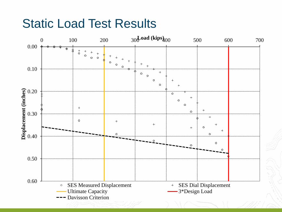
0.00
0.10
0.20
0.30
0.40
0.50
0.60
0 100 200 300 400 500 600 700
Dis
pla
cem
ent
(in
ches
)
Load (kips)
SES Measured Displacement SES Dial DisplacementUltimate Capacity 3*Design LoadDavisson Criterion
Static Load Test Results
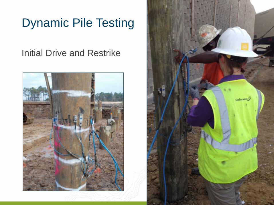
Dynamic Pile Testing
Initial Drive and Restrike

52
Pile Driving Analysis
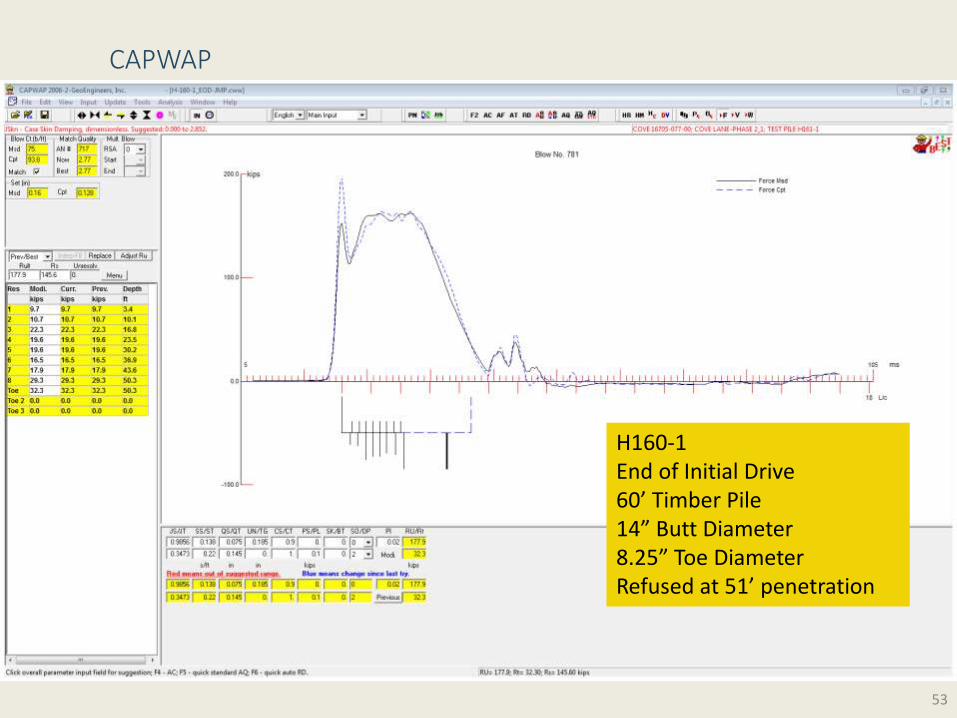
53
H160-1 End of Initial Drive 60’ Timber Pile 14” Butt Diameter 8.25” Toe Diameter Refused at 51’ penetration
CAPWAP
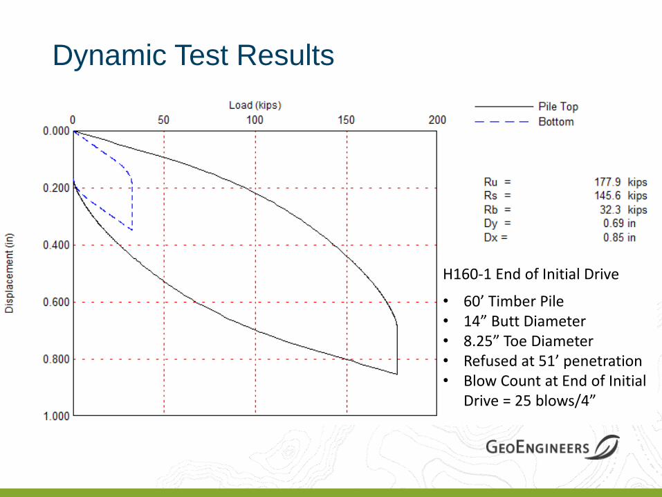
Dynamic Test Results
• 60’ Timber Pile • 14” Butt Diameter • 8.25” Toe Diameter • Refused at 51’ penetration • Blow Count at End of Initial
Drive = 25 blows/4”
H160-1 End of Initial Drive
55
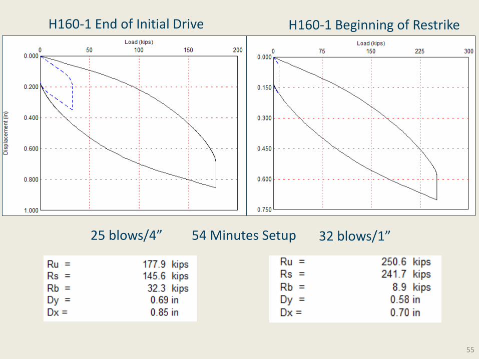
H160-1 End of Initial Drive H160-1 Beginning of Restrike
25 blows/4” 32 blows/1” 54 Minutes Setup
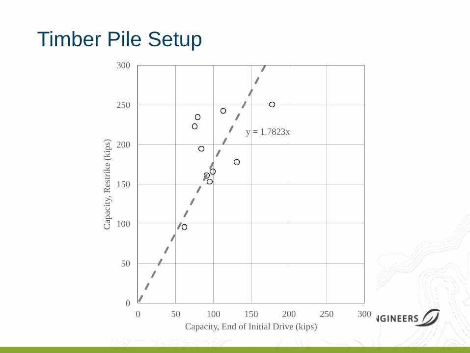
y = 1.7823x
0
50
100
150
200
250
300
0 50 100 150 200 250 300
Cap
acit
y, R
estr
ike
(kip
s)
Capacity, End of Initial Drive (kips)
Timber Pile Setup

57

59
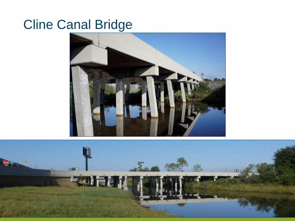
Cline Canal Bridge
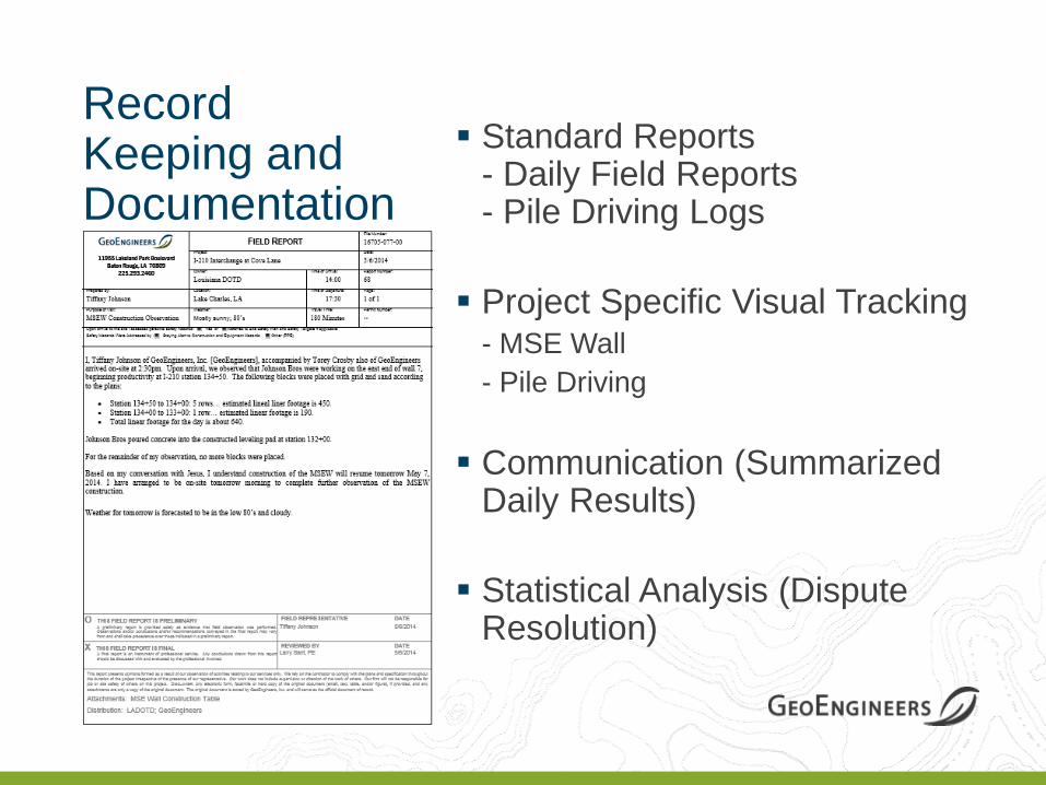
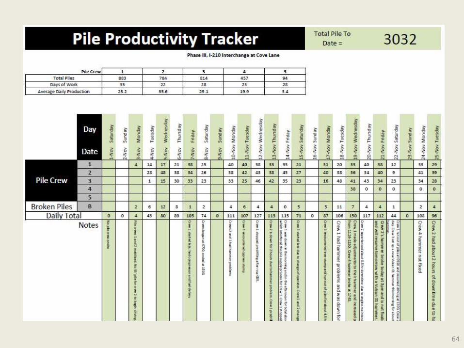
Record Keeping and Documentation
Standard Reports - Daily Field Reports - Pile Driving Logs
Project Specific Visual Tracking - MSE Wall
- Pile Driving
Communication (Summarized Daily Results)
Statistical Analysis (Dispute Resolution)

Documentation
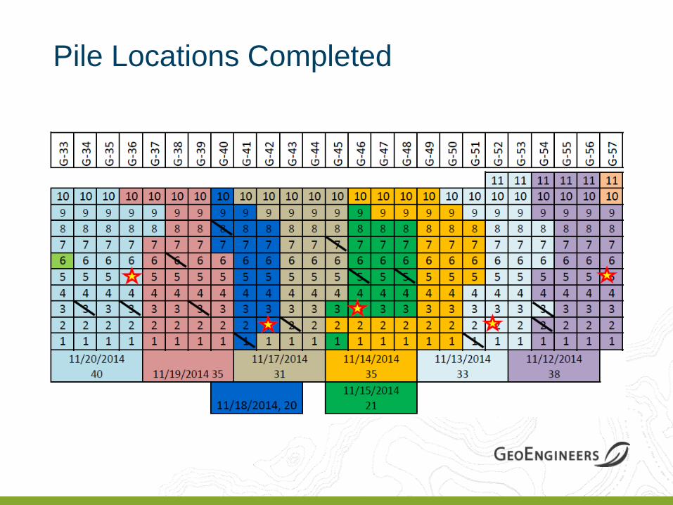
Pile Locations Completed
64
Conclusions
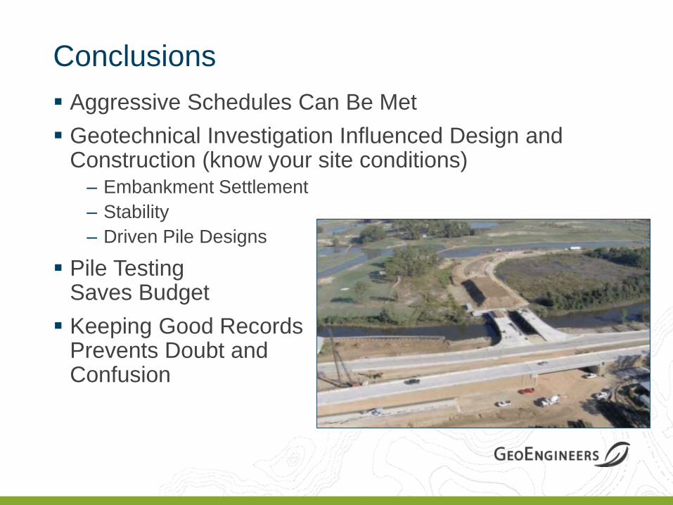
Conclusions
Aggressive Schedules Can Be Met
Geotechnical Investigation Influenced Design and Construction (know your site conditions) – Embankment Settlement
– Stability
– Driven Pile Designs
Pile Testing Saves Budget
Keeping Good Records Prevents Doubt and Confusion
67
Questions?
Questions?
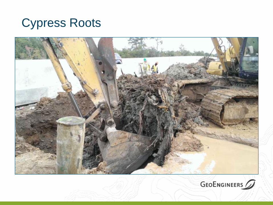
Cypress Roots


