
HR30
Hy-Security Gate Operators
HRG 220 SWING GATE OPERATOR, SINGLEHRG 222 SWING GATE OPERATOR, PAIR
HANDBOOK
Manufacturers and Designers of Hydraulic Systems


3
2
1
NOTE: ALL LATERAL FORCES MUST BE SUPPORTED BY BACKING POST/PILASTER.
SINGLE POST SHOWN. OPPOSITE POST SIMILAR MIRROR IMAGE.
CUSTOM DIMENSIONS MUST BE APPROVED BY FACTORY BEFORE ORDER IS ACCEPTED.
CUSTOM HEIGHT ADDS TO THIS DIMENSION.
seattle, washington
TITLE
DRAWING NUMBER:
1 1SHT OF
HR34
REVDRAWN
APPROVED
CHECKED
DATE
DATE
DATE
6/23/00KERIPART NUMBER
N/AA
912" 7"
8"
16 12"3"
3"
7"
12"
9"
1 12"
1112"
9"
14 12"
12"
81"
57"
10"5"
9"
1238"
60"
8"
CUSTOM HEIGHT
"
LOCATION OFOPTIONAL 2nd
INDEX ARM
"
"
CUSTOM HEIGHTINDEX ARM BRACKET
3" X 3"HINGE
BEARINGACCESS PANEL
LIMIT SWITCHACCESS PANEL
STANDARDINDEX ARM
BRACKET
HOSE ACCESS PANEL
TYPICAL TOP CAP INSTALLATIONSFOOTPRINT DIMENSIONS
6" PIPE BRACKET
4" PIPE BRACKET PILASTER BRACKET
5/8" SQUARE
ENGRNG REL NOTICE
ERN000043
3/4" BOLT HOLES(2 PLACES)
3/4" MOUNTINGSLOTS (4 PLACES)
BASE PLATE
CUSTOM REQUEST STANDARD DIMENSIONS1 2
3
6" X 6" PLATECUTOUT
13"


Operator MaintenanceOperator MaintenanceOperator MaintenanceOperator MaintenanceOperator MaintenanceHydraulic System
Fluid Level: Under normal conditions, hydraulic systems do not consume oil. Before adding any oil, check thesystem thoroughly for leaks. Remove the bright metal plug in the tank, fill to plug level, then replace plug. Werecommend our Uniflow hydraulic oil, part number H-004, which is sold in one gallon containers by our distribu-tors. Automatic transmission fluid may be used, although its performance in cold weather will be sluggish unlessthe operator is well heated. Do not use brake fluid.
Look for leaks: Occasionally there may be slight seeping at the fittings after some usage. Tightening of the fittingswill usually correct the problem. If the leaking persists, replace "O" rings, fittings or hoses, if required. No furtherleaks should occur.
Oil Change: A hydraulic system does not foul its oil, unlike a gas engine, so oil changes do not need to be frequent.Rather, heat breakdown is the main concern in a hydraulic system. If the unit is subjected to high use, especially ina warm climate, change the oil more frequently. In general, we recommend draining the reservoir and replacing theoil at five or ten year intervals.
There are several ways to change the hydraulic oil, depending on the type of operator being serviced. If youdon’t know how to drain the oil, contact your distributor for directions. Refill with new Uniflow hydraulic oil(available from your distributor). To avoid overfilling, never pour into the port where the black breather cap islocated. Instead, remove only the bright metal plug in the tank. Slowly pour the oil into the tank until the oil iswithin one inch of the filler port. Replace the plug and wipe up any spilled oil.
Cold Weather: 1. Check that your reservoir is filled with Uniflow high performance oil. 2. Ice can partly or totally jam gate operation. Check by operating the gate manually.
Electrical ControlsBefore servicing, turn off power disconnect switch
No routine maintenance is needed for the electrical system or controls. If the environment is very sandy or dusty, sealall holes in the electrical enclosure. Blow dust out of the electric panel with compressed air. A qualified electrician maytroubleshoot with the aid of the electrical drawings in Appendix 4.
If it is necessary to call a distributor for assistance, be sure to have your model and serial number ready. Other helpfulinformation would include the name of the job, approximate date of installation, and the service record of the operator,especially any work that has been done recently. Be prepared to describe as exactly as you can what the machine is oris not doing. Describe any unusual sounds or location of oil leaks.
How to Adjust the Pressure Relief Valve: To check your relief valve setting, first disconnect one of the hoses.Run the operator either open or closed (the gate will not move with the hose disconnected. The relief valve is foundon the rear of the hydraulic power unit. It has a hex adjusting head and lock nut. To adjust, loosen the lock nut andscrew the threaded bolt clockwise for increased pressure, counterclockwise to decrease pressure.
MODEL FACTORY SETTING111 Series 750 psiSS, E Models 1000 psiEX Model 1300 psi444 Series 1300 psi
Do not attempt to use the relief valve as an entrapment protection device. Photocells or gate edges are the bestmethods to protect pedestrians and reserve power to the drive gate.
5/25/00 G39


Field Hose Measurements forHVG and HRG Operators
When field measuring for the necessary hose length to order, the following may be helpful:
There is little room in the base of the HRG or the HVG operators and limited room in thecontrol/power panel, therefore, your field measurements must be very accurate whencalculating the length of the necessary hydraulic hoses. If your dimensions are too little, youwill not reach the connections, if your measurements are too long, you will have troublefinding space for the excess hose.
Remember that two hoses are needed for each motor or each cylinder. This means that youneed four hoses when you are dealing with a HVG operator and also when you are installing aHRG 222 (pair) operator.
#3
#4
#2
#5
#1Roadway
Be sure to measure accurately the following distances: (the best way is to pull a cord throughthe conduit, mark it, and then measure it.)
1. The bottom of the pump/control panel to the bottom of the trench.2. The total distance across the trench.3. The distance back up to the bottom of the operator.4. Add approximately 6" for the hoses to reach up into the operator.5. Add approximately 24" for the hoses to reach up into the power/control panel.
The part numbers for the hoses are:
1/4" hose for HRG: H SFHO 004 SW3/8" hose for HVG: H SFHO 006 4216
For assistance call your distributor.
#2 (if necessary)
2 ea. hydraulic hosesin 2" conduit
3/4" conduit for electricalonly
5/11/00 HV/HR45

INSTALLATION INSTRUCTIONS FOR HRG SWING GATE OPERATORINSTALLATION INSTRUCTIONS FOR HRG SWING GATE OPERATORINSTALLATION INSTRUCTIONS FOR HRG SWING GATE OPERATORINSTALLATION INSTRUCTIONS FOR HRG SWING GATE OPERATORINSTALLATION INSTRUCTIONS FOR HRG SWING GATE OPERATOR
1. Permanent Wiring Shall Be Employed. Run wire in conduit and wirenut to the loose wires that are connectedto the disconnect switch. The disconnect switch is located on the baffle surrounding the electric control panel.
Note 1: Proper grounding is required and grounding wire is located in the disconnect switch area. Note 2: Before servicing or opening electrical panel, be certain to turn off all electric power.
2. Button Station Operation: Install the push button control station within sight of the gate. Be sure gate openingis clear before operating gate. Connect the push button to the terminal strip as detailed on drawing E57. If thedistance is greater than 200 feet, see E71 for details on long range pushbutton control.
3. Entrapment Protection - minimum safeguards: A. Since automatic gates are not intended for pedestrian use, always install a separate pedes- trian walkway and access gate. Install signs which direct persons to use the pedestrian gate, and to not enter through the vehicle gate. B. Be certain that all operating switches are located at least a six foot distance from the gate, to reduce the possibility of any attempt to reach through in order to operate the gate. C. Be certain to mount at least two of the enclosed 8-1/2" x 11" warning placards on each side of the gate to warn users of the hazards of a power operated gate. D. Automatic Operation: Entrapment protection sensors must be installed to guard both the opening and closing of the gate. Install two photo electric eyes, or attach a minimum of two edge sensors to create a reversing function for each direction of gate travel. All sensors guarding the closing direction connect to terminals #1 and #6 in the control box. All sensors guarding the opening direction connect to terminal #9 and #6. See drawing E41 for mounting and connection details of the edge sensors.
Caution: Vehicle detectors are not entrapment protection sensors.
4. Using 5/8"-3/4" anchor bolts, mount operator base with proper clearance from square tube to backing post. Seedrawing HR34 for dimensions. It is important that the finished installation be plumb and true. Use shims ifnecessary to level the operator base.
5. Attach the top of the operator to the backing post or supporting wall, using the bracket provided. The attachingbracket "sleeves" inside the top of the operator post. Note: The backing post/column, (provided by others) mustaccomodate all of the "tip over" loads imposed by the gate panel.
6. Mount the controller box near the gate operator. See drawing G39.
7. Pull six wires minimum (eight wires if close position indication is required) from control panel to junction areain the base of the operator post assembly. This may be either by underground conduit or by a seal-tight conduitmounted into the side of the base.
8. HRG operators normally do not ship with the hydraulic hoses included, until the exact length is specified bythe installer. See HV/HR45 and verify correct length has been ordered.
9. Pull the hoses in a 2" minimum conduit and connect, being certain to match the color coded ends. Also be certainthat the connectors are firmly snapped together.
10. Remove the lowest cover plate to expose the limit switches and connect the limit switch wiring according tothe tagged terminal numbers on the prewired cords. See HRG Electrical Connection Diagrams for moreinformation.
page 1 of 2 6/13/00 HR21b

11. Remove the shipping plug on the pump manifold and replace with the vented cap that is provided.
12. Connect appropriate power wiring to match voltage and phase of the operator. Be certain to oversize feederwires to allow for voltage drop (see wire size schedule, E16a & E16b), especially for single phase machines.Machines to operate on high voltages (above 120 VAC) do not need a neutral wire. Wirenut the power feedersto the loose wires at the back of the On/Off switch.
13. Verify that the primary tap of the control transformer is connected to match the supplied voltage.It is especially important to distinguish between 208 and 230 volt supplies. The various voltage taps are identifiedby a label on the transformer or in the electrical drawings.
14. Test basic functions of the operator first, before connecting any external control wiring. If your operator isequipped with vehicle detectors, be certain that they are connected to a loop or unplugged so that they do not causeinterference with the function of the machine. If the motor turns, but nothing moves, reverse two poles of a threephase power source. Also check that the by-pass valve is closed. Push in the round black knob that is located onthe right side of the pump manifold. Also be certain that the hose quick connectors are firmly engaged.
15. After testing the basic functions, follow our electrical connection diagrams to add any accessories or externalcontrol wiring. Test the operator functions again.
16. Check the "soft stop" open timer, which is mounted on top of the control relay. The label on the timer dialshows the minimum and maximum settings. In operation the timer only needs to be set long enough for thegate to coast to a smooth stop after opening. There is no bad effect if the timer is set for too long, except thatthe operator cannot be started closed until this timer times out.
Additional instructions, gate tensioner and lock pin assembly
1. Install the gate using the clamps provided and adjust for the correct clearance between the gate and the roadsurface. Allow three inches clearance at the far end of the gate panel. See drawings for gate panel clearancedimensions.
2. Clamp the index arm mounting bracket near the bottom of a vertical member of the gate. The best attachmentpoint is at the one-third to one-half of the gate length from the gate hinge.
3. Cut the index arm arm to the correct length. Connect the threaded rod end to the mounting bracket on the gatepanel. Drill a ½” hole and bolt the other end of the index arm to the mounting bracket on the operator post assembly.
4. Mount the locking pin mechanism on the lower corner of the free end of the gate panel in such a position thatthe pin penetrates 2" into a lock receptacle when the gate is fully closed.
5. Bury a tube in the roadway to act as a receptacle for the locking pin. The tube should have an angular cut onthe tip and project about two inches above the grade to act as a "catch" for the locking pin. Use a 3-1/2" x 1-1/2"tube of appropriate length for this purpose. Use blacktop or grout to create a mound around the exposed tube, sopassing vehicles encounter a smooth bump.
NOTICE: If the locking pin mechanism is not used, security of this system is adversely affected and the operatordrive shaft may be exposed to high stresses by wind loading or vandals. If the lock pin receptacle is not built orinstalled to create a strike stop for the gate, the lock pin may not always align with the receptacle.
6. Adjust the threaded end of the index arm rod to place the far end of the gate in an exact position for the lockingpin to strike and slide down into the receptacle as the gate closes. The most reliable index arm adjustment will allowthe gate to swing slightly past center so that the lock pin firmly strikes the back of the receptacle and is held firmlyin that position. Tighten all parts of the index arm assembly firmly for trouble free operation.
page 2 of 2 6/13/00 HR21b

ADJUSTMENT OF FLOW CONTROL REGULATING VALVESADJUSTMENT OF FLOW CONTROL REGULATING VALVESADJUSTMENT OF FLOW CONTROL REGULATING VALVESADJUSTMENT OF FLOW CONTROL REGULATING VALVESADJUSTMENT OF FLOW CONTROL REGULATING VALVESON SWING GATE OPERATORSON SWING GATE OPERATORSON SWING GATE OPERATORSON SWING GATE OPERATORSON SWING GATE OPERATORS
HRG 220 swing gate operators have at least two flow control regulating valves. The flow control valve(s) needto be adjusted correctly for proper performance of the gate operator. The flow control valve is the small squarebrass valve device with the knurled adjusting knob, located just above the quick-disconnect fitting to the hydraulichoses. The most important flow control adjustment is the one governing the closing of the gate. The closingflow control is the valve just above the quick-disconnect fitting that is painted red. Because the gate drops as iscloses, gravity could over-accelerate the gate, depending on it's weight. The job of the flow control valve is toregulate the closing speed by preventing over-acceleration in the close cycle. The flow control is not intended tobe used as a true speed adjusting control valve because it would create a tremendous inefficiency if over-tightened.
To Adjust the close flow control valve correctly, start with the valve fully open, (all color bands exposed) andturn clockwise until you have achieved proper gate control in the closed direction. Because of the low flow rateof the HRG operator, correct adjustment will be at the bottom third of the color bands on the flow control valve.The most crucial part of the closing of the swing gate is when the lock pin strikes it's receptacle. The flowcontrol valve adjustment is most helpful for maintaining control at this point of operation. (Other importantadjustments are available for correct locking. See separate instructions on "Adjustment of Indexing Arm")
Adjustment of the flow control valve affecting the opening, is much less important. Set the valve at approximately3 turns from fully closed, or in a position that creates the smoothest operation.
The HRG 222 pair of swing gates will have two flow control valves for the close direction and two for the opendirection. The close flow control valves adjust the same as single HRG operators except that the valve governingthe master post (post with the limit switch) must be set to cause the master gate post to operate slightly slowerthan the slave gate post. Because there is only one limit switch for two gate posts, it is important that the slavepost reach the fully closed position before the master post. The master post will shut down power to both postswhen it reaches the fully closed position. The flow control valves for the open direction are adjusted only toslightly slow the master opening speed to assure the same delay in limit function. The only other use for the flowcontrol valves is to help prevent the force of wind gusts from over-accelerating the gate.
Caution: Over-tightening of the flow control valves will cause the operator to draw more motor horsepowerthan necessary or desirable.
Be certain to tighten the set screws on the adjusting knobs to lock your adjustments.
6/9/00 HR46

The procedure for manual operation follows. During a power failure, accident or seriousmalfunction of the equipment, it is important to follow this procedure.
1. Turn off electrical power switch to the controller.
2. Unlock the locking pin (at the far end of the gate panel) and lift the pin out of it's receptacle.
3. Remove the bolt , or padlock, from the index arm mount on the operator post assembly and swingaway the entire index arm assembly. The gate panel is now free to swing on its auxiliary hinges.
4. If your operator is equipped with an optional accessory hand pump, manual operation can beachieved from the control enclosure without using any mechanical releases. TO CLOSE THE GATE:Simply operate the hand pump, located in the lower portion of the control enclosure. TO OPEN THEGATE: pull and twist the knurled knob on the solenoid directional valve, (below the electric motoron the hydraulic pump) then operate the hand pump.
NOTE: To return the valve to normal operation, be certain to release the knurled knob on the directionalvalve by twisting it clockwise.
For assistance call your local Distributor.
Operation Instructions for Manual or Emergency SituationsOperation Instructions for Manual or Emergency SituationsOperation Instructions for Manual or Emergency SituationsOperation Instructions for Manual or Emergency SituationsOperation Instructions for Manual or Emergency SituationsHRG Swing Gate OperatorHRG Swing Gate OperatorHRG Swing Gate OperatorHRG Swing Gate OperatorHRG Swing Gate Operator
5/10/00 HR23

Pushbutton Control Wiring
16 ga 125' Maximum14 ga 200' Maximum12 ga 300' Maximum10 ga 500' Maximum
Wire Size SchedulesWire Size SchedulesWire Size SchedulesWire Size SchedulesWire Size Schedulesfor 1/2-hp through 5-hp motors
Supplying a gate operator with the right electrical service is crucial to the way the performance ofthe operator the life of its electrical components. If the wire size used is too small, the voltage loss—especially during motor starting—will prevent the motor from attaining its rated horsepower. Thepercent of horsepower lost is far greater than the percentage of the voltage loss. A voltage loss couldalso cause the control components to chatter while the motor is starting, substantially reducing theirlife due to the resultant arcing. There is no way to restore the lost performance resulting fromundersized wires, except to replace them; therefore it is much more economical to choose a sufficientwire size at the initial installation.
The tables on the following page are based on copper wire and allow for a 5% voltage drop. Theampere values shown are the service factor ampere rating (maximum full load at continuous duty)of the motor.
Always connect in accordance with the National Electrical Code, article 430, and other local codesthat may apply.
The maximum distance shown is from the gate operator to the power source; assuming that sourcepower is from a panel box with adequate capacity to support the addition of this motor load. Thevalues are for one operator, with no other loads applied to the branch circuit. For two operatorsapplied to one circuit, reduce the maximum allowed distance by half.
Use this chart to determine maxi-mum allowable control wiring dis-tance. If the location required ex-ceeds the distances listed on thechart at the right, addition of a longrange interface will be neccessary.
4/14/00 E16a

Wire
Size fo
r Vo
ltag
e D
rop
Ov
er D
istan
ce
E1
6b
Wire Sizes for Power Wiring, Single Phase Distances are shown in the unshaded boxes
Wire G
augeW
ire Gauge
Always connect in accordance with the National Electrical Code, article 430, and other local codes that may apply.
Wire sizes for Power Wiring, Three Phase Distances are shown in the unshaded boxes
115 V, SINGLE PHASE 208 V, SINGLE PHASE 230 V, SINGLE PHASE
Amps 10.0 11.06 14.4 27.2 NA NA 5.5 6.1 7.6 14.2 16.2 NA 5.0 5.8 7.2 13.6 14.8 27.0
Horse 1/2hp 3/4hp 1hp 2hp 3hp 5hp 1/2hp 3/4hp 1hp 2hp 3hp 5hp 1/2hp 3/4hp 1hp 2hp 3hp 5hpPower
12ga 90 75 60 30 290 260 205 110 100 350 300 245 130 120 65
10ga 140 120 100 50 460 415 330 175 155 560 480 385 205 190 105
8ga 220 190 155 80 725 650 525 280 245 880 760 610 325 300 165
6ga 350 300 245 130 1,150 1,040 835 445 390 1,400 1,120 975 515 475 260
4ga 555 480 385 205 1,825 1,645 1,320 710 620 2,220 1,915 1,550 815 750 410
2ga 890 765 620 330 2,920 2,630 2,110 1,130 1,000 3,550 3,060 2,465 1,305 1,200 660
208 V, THREE PHASE 230 V, THREE PHASE 460 V, THREE PHASE
Amps 2.7 3.1 4.2 6.5 6.7 16 2.4 3.0 3.8 6.2 6.4 15.4 1.2 1.5 1.9 3.1 3.2 7.7
Horse 1/2hp 3/4hp 1hp 2hp 3hp 5hp 1/2hp 3/4hp 1hp 2hp 3hp 5hp 1/2hp 3/4hp 1hp 2hp 3hp 5hpPower
12ga 590 510 375 245 235 100 730 585 460 280 270 115 2,915 2,350 1,850 1,130 1,100 455
10ga 930 810 600 390 375 160 1,160 930 730 450 435 180 4,640 3,710 2,930 1,800 1,740 725
8ga 1,475 1,285 950 615 595 250 1,835 1,470 1,160 710 690 285 7,340 5,870 4,650 2,840 2,750 1,150
6ga 2,350 2,045 1,510 975 945 400 2,925 2,340 1,845 1,130 1,095 455 11,700 9,350 7,400 4,550 4,400 1,800
4ga 3,720 3,240 2,390 1,545 1,500 630 4,625 3,700 2,920 1,790 1,735 720 18,500 14,800 11,700 7,200 7,000 2,900


����������������� �����
�������
��������� ��������
��������� ��������

Long Range Pushbutton ControlLong Range Pushbutton ControlLong Range Pushbutton ControlLong Range Pushbutton ControlLong Range Pushbutton ControlConnection Diagram
Voltage loss over distance is caused as a function of control amperage multiplied by the resistance ofthe wiring, and may be expressed: Voltage loss = (wire resistance) X (control amperage). Thislimits pushbutton control wiring to the following schedule:
16 ga. wire= up to 125 feet max 12 ga. wire = up to 300 feet max14 ga. wire = up to 200 feet max10 ga. wire = up to 500 feet max
For applications requiring pushbutton controls from a long distance, or circuits of limited current,order the factory modification, long range interface. The following schedule indicates the improvedcontrol range using the long range interface:
16 ga. wire = up to 50 miles 20 ga. wire = up to 19 miles18 ga. wire = up to 30 miles 22 ga. wire = up to 12 miles
Be certain to remove factory-installed jumper (#2 to #4) and also verify that no other external stopbutton is connected at #2 and #4.
When the long range interface option is used in conjuction with a pushbutton control, connect to theoperator as shown below:
FOR BEST PERFORMANCEUSE 20 GAUGE WIRE OR LARGER
OPEN
CLOSE
STOP
COM
STP
CLS
OPN LT. GREEN
LT. BLUE
ORANGE
YELLOW (COM)
DK BLUE
DK GREEN
BLACK
BLACK24V SUPPLY
RED
WHITE(COM) 4
2
3
1
10
2
TO TOC OO PN ET RR AO TL OS R
REMOTE PUSHBUTTONLONG RANGE
INTERFACETERMINAL
STRIP
NOTE:The part number for the long range interface, installed at the factory, A EIIF 001 OCSThe same part designation for the long range interface, in kit form, A EKIF 001 OCS
5/10/00 E71

Master/Slave Interconnection InstructionsMaster/Slave Interconnection InstructionsMaster/Slave Interconnection InstructionsMaster/Slave Interconnection InstructionsMaster/Slave Interconnection Instructions
Operation of two Hy-Security gate operators as a master/slave pair is simply a matter of correctlyinterconnecting the two control circuits. Join the following four wires from the master operator to the slave:
Terminal #1 master to terminal #1 slave,Terminal #3 master to terminal #3 slave,Terminal #4 master to terminal #4 slave,
*Terminal #10 master to terminal #10 slave
All stop control inputs must be connected to the master operator only. The slave operator must not have anyconnection between terminal #2 and terminal #4, such as a stop button or jumper.
*On DC battery powered operators, interconnect the black wires (-) to the on/off switch instead of the #10wires. This prevents one operator from powering the other when the disconnect switch is off.
For assistance call your Distributor.
FOR ALL MODELS EXCEPT: HTG 320
5/15/00 E36

Installation Instructions For Gate Reversing Sensing EdgeInstallation Instructions For Gate Reversing Sensing EdgeInstallation Instructions For Gate Reversing Sensing EdgeInstallation Instructions For Gate Reversing Sensing EdgeInstallation Instructions For Gate Reversing Sensing Edge
1. Securely bolt the edge sensor to the edge of the gate. The edge should line up with the lower corner of thegate frame.
2. If the reversing edge is to wire directly to the gate operator:
A. Locate a mounting position for a curl cord attatchment, or retracting cord reel holder where there will be no possibility of the cord rubbing on the moving gate panel.
B. Attatch the cord to the gate in a position that is roughly near the position of the automatic operator, when the gate is closed.
C. Route the wires to the leading edge of the gate and join to the wires of the reversing edge. Wirenut and thoroughly tape the connections so that they are not prone to vibrate loose.
D. Join the fixed end of the cord reel or curl cord directly to terminal numbers 1 and 6 inside the control box of the operator.
3. If the reversing edge is to transmit to the gate operator:
A. Mount the reversing edge transmitter (Multi Elmac Model #3022, or equivalent) onto the gate panel near the upper corner of the leading edge of the gate.
B. Join the wires of the reversing edge to the two terminals inside of the edge transmitter. Set a unique code on the “DIP” switches inside the transmitter. Remount the cover of the transmitter and tighten the screws firmly so that no water will leak inside.
If a receiver for the reversing edge has been prewired inside the operator, proceed directly to step #3D.
C. Mount a commercial style radio receiver* (one with a connector for an external antenna) on the inside of our operator enclosure. Connect the 24 Volt supply wires to terminal numbers X1 and 10 on the terminal strip. Connect the radio contact wires to terminal numbers 1 and 6 on the terminal strip.
D. Mount an external antenna onto the top of a fixed post of the fence near the operator. Connect the antenna into the socket on the radio receiver.
E. Set the “DIP” switches in the receiver to match the same code used in the edge transmitter.
*If there is also to be a radio receiver for a hand held transmitter to operate the gate, be certain to use a twochannel commercial receiver.
4. Test the operation of the reversing edge to be certain that it is functioning. Advise the user of the gate to becertain to retest this vital function weekly.
4/17/00 E41

Photoelectric Eye, Reflector Adjustment InstructionsPhotoelectric Eye, Reflector Adjustment InstructionsPhotoelectric Eye, Reflector Adjustment InstructionsPhotoelectric Eye, Reflector Adjustment InstructionsPhotoelectric Eye, Reflector Adjustment Instructions
Correct installation and alignment of a retro-reflective photo eye and its reflector are important for atrouble free installation. Systems operating at a range of 15’ or more are prone to weather causedreductions in range. We feel that if care is taken in the initial mounting and alignment of the 13”reflector then the chance of problems is greatly reduced. Taking steps to protect the reflector frombeing exposed to fog and being absolutely certain the photo eye is perfectly aligned will greatlyincrease the apparent power of the photo eye.
The ideal mounting for the reflector is suspended inside a 12” long piece of 3” P.V.C. conduit. Cutthe opening of the 3” P.V.C. conduit at a 45 degree angle to act as a drip shield. The reflector is heldagainst the backside of the 3” conduit by attaching a 3” male connector. Do not cement the connectorso that the reflector can be reached for future cleaning. To create a mounting base, attach a 3” alumi-num meter hub or flange to the connector. The whole package can now be mounted to any flatsurface.
Locating the reflector in the center of the invisible beam of infrared light is important to achieve themost sensitive alignment. The center is determined by the following test. While holding the reflectorin your hand, slowly raise it until the beam is no longer returned and the photo eye trips. Mark thismaximum height. Now lower your hand and determine the lower limit of the infrared beam bywatching the trip point. Mark this position well. Repeat the same procedure for left and right at thecenter elevation of the beam, as determined by the previous test. Once the four limits have beendetermined, either mount the reflector in the center of the area outlined or realign the eye for theposition of the reflector. If the photo eye is realigned, be sure to perform the centering test again toverify that the reflector is truly in the center.
As a last tip, smearing dish soap on the reflector will also help to repel any possibility of foggingfrom moisture that gets into the 3” pipe. With all of these steps taken, the optimum performance ofthe retro-reflective photo eye system will be achieved.
Note: To cover greater distances, or to operate in adverse weather conditions, consider a through-beam photo eye.
For Assistance call your Distributor.
4/17/00 E17

Detector Installation GuideDetector Installation GuideDetector Installation GuideDetector Installation GuideDetector Installation Guide
Loop BasicsThe vehicle detector passes a small current flow through the “loop” which then becomes an inductive coil.When a vehicle passes over a loop the detector senses the resultant drop in the inductance, and actuates it’soutput relay.
Loop ConfigurationsConfigurations differ depending on the application. In parking applications with our HTG320 operator,a loop may be as small as 3’ x 6’. In traffic applications employing one of our sliding gate operators,or swing gate operators, the smallest loop should not be less than six feet square.
Rules to Follow for Security Gate Applications1. The side of the loop closest to the gate shall be located at least four (4) feet distant from it’s line of travel.
2. The shortest side of the loop shall be between six (6) and eight (8) feet in length. The longest side of theloop shall be between six (6) and twenty (20) feet in length. For applications that need to span a wide area,use several smaller loops. Do not exceed a maximum of 200 square feet of loop area to only one detector.
3. In applications with multiple loops, keep each loop at least six feet apart. This avoids “cross talk”. It ispossible to have loops closer together by selecting different frequencies.
4. For greater sensitivity and less chance of false calls caused by the motion of the gate, it is better to use twosmaller loops, connected in a series circuit, to one detector instead of one large, single loop.
5. To avoid interference, keep loops at least two (2) inches above any reinforcing steel. Do not route loopwires with, or in close proximity to, any other conductors, including other loop leads, unless shielded lead-in cable is used.
6. Loop and lead-in wire should be one continuous piece. Avoid splices, if possible. If a splice is necessary forany reason, “pot” the splice in epoxy or use heat shrink to ensure that the quality of the splice covering isthe same as the original wire jacket.
7. Use only number 12, 14, or 16 gauge stranded wire with a direct burial jacket. Cross linked polyethyleneinsulation types, such as, XLPE or XHHW, will last much longer and are less prone to damage duringinstallation than conventional insulation types. Preformed loops can be used before road surfacing or underpavers.
8. Twist loose tails of lead-in wires tightly, approximately ten times per foot.
Twist lead-in at least 10 turns per foot Twist Like This
Like This Not Like This 4/13/00 E31a

continued from previous page...continued from previous page...continued from previous page...continued from previous page...continued from previous page...
9. Follow this guide for the correct number of turns in the loop; 12 to 20 sq. ft = 5 turns 20 to 60 sq. ft. = 4 turns 60 to 240 sq. ft. = 3 turns
10. This guide is written from a design perspective, but installation workmanship practices are equallyimportant to insure proper operation and long loop life. The best way to insure a quality installation is toemploy a professional installer experienced with detector loops. A few important practices are: A. The slotin the surface should be cut ¼” wide x 1 ½” deep. B. The corners of the cut must be at an angle or coredrilled to relieve stress on the wires. C. After the wire is installed, the slot must be completely backfilledwith a non-hardening sealer. Note that if the loop wires are able to move in the slot after the sealer has set,the detector may give false calls.
Detector LogicHy-Security Gate Operators recommends that vehicle detectors be used for free open and obstruction sensinglogic only. The exception is in parking applications with our HTG320 operator where detectors may be alsoused to close the gate. In applications employing our swing , vertical lift, or sliding gate operators, closinglogic cannot be used. Because of their slower speeds, closing logic is a poor choice for security gate systems.Since there are several ways that the gate may be left standing open and because there is a loss of safety. Ourcircuit has not been designed to accomodate “detect to close” logic.
Loop DiagnosticsThe following tests cannot guarantee a functioning loop, but failure of either test means that the loop isdefinitely suspect, even though it may still be functioning at the time.
Test #1:Resistance of the loop and lead-in wire should not exceed 4.0 Ohms.
Test #2:The resistance to earth, as measured with a 500V “Megger”, should be 100 Megohms or more. Loops mayfunction at 10 Megohms or less but will not be reliable (e.g. when the ground is wet from rainfall). Lowresistance indicates broken or moisture saturated insulation. This is common if inappropriate wire insulationhas been used.
Loop Sealant
Like This NOT Like This OR This
4/13/00 E31b


Pressure Relief ValvesPressure Relief ValvesPressure Relief ValvesPressure Relief ValvesPressure Relief ValvesAdjustment ProceduresAdjustment ProceduresAdjustment ProceduresAdjustment ProceduresAdjustment Procedures
The relief valve can be found on the back side (gate side) of the hydraulic power unit. It is the only compo-nent located here and has a hex adjusting head and lock nut. To adjust setting, loosen the lock nut screw thethreaded bolt CW for increased pressure, turn CCW to decrease pressure.
Pressure relief valves are preset at the factory to utilize maximum available horsepower. The relief valve canbe lowered to smooth starting if necessary. This is most easily done by decreasing the pressure until the gateoperation slows, and then increasing the pressure just enough to provide normal gate speed.
It must be understood that if you reduce the pressure setting, you will lose horsepower to move the gate ifadditional resistance (old gate hardware, snow and ice, etc.) is encountered.
Do not attempt to use the relief valve as an entrapment protection device. A photo eye or a gate edgeis the best method to protect pedestrians and reserve power to drive the gate.
5/22/00 G40
Side View Front View
Model Factory Setting
111 Series 750 psi222 SS, E 1000 psi
222 EX 1300 psi444 Series 1300 psiHRG Series 1300 psiHVG Series 2000 psiHTG 360 1000 psiHTG 320-6 1000 psiHTG 320-3 1000 psiHTG 320-2 700 psi

Maintenance ProceduresMaintenance ProceduresMaintenance ProceduresMaintenance ProceduresMaintenance Procedures HRG Swing GateOperator HRG Swing GateOperator HRG Swing GateOperator HRG Swing GateOperator HRG Swing GateOperator
5/10/00 HR37
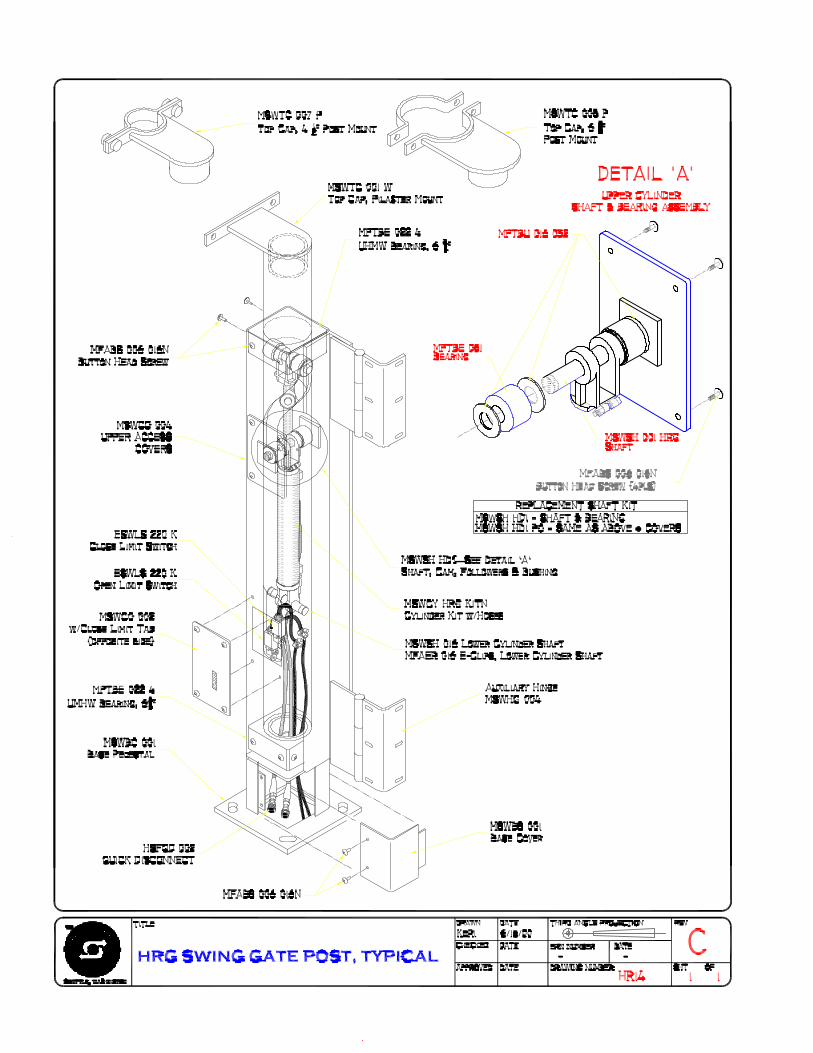
OPERATOR POST
The Hy-Security Swing Gate Operator is designed to require a minimum amount ofmaintenance.
There is no required lubrication of any part of the operator, including the cam follow-ers located at the center of the operator. The cam followers are permanently lubri-cated at the factory.
Inspect the white UHMW plastic bearings at inside top & bottom of the 7" squarepost. If the gap between the bearing and the 5-1/2" round post exceeds 3/8", replacethe bearing.
Inspect the open and close operation of the gate for speed and smoothness of travel.If adjustment is necessary, refer to the information on adjustment of the flow controlvalves.
The adjustment of the indexing arm may have to be altered to hold the gate in thecorrect position and allow alignment of the locking pin with it's receptacle. Adjust-ment is usually required only after the gate has been hit by a vehicle or otherwisebeen damaged. To adjust, unbolt the tension where it attaches to the gate and screwthe adjustor, in or out as needed.
The most reliable operation occurs when the indexing arm is adjusted to slightly "overclose" the gate. The goal is to have the locking pin strike its receptacle firmly thenthe closing tension will aid in keeping the locking pin aligned into the receptacle.
For assistance, contact your distributor.

Conversion of Primary Operator VoltageConversion of Primary Operator VoltageConversion of Primary Operator VoltageConversion of Primary Operator VoltageConversion of Primary Operator Voltage
These instructions do not apply to conversions from single phase to three phaseor vice versa. Conversion from one phase to another is not recommended.
Steps required to convert the voltage of an operator within the same phase:
1. The overload must be changed to match the motor current at the new operating voltage.To do this, remove the overload device from the contactor by loosening the three screws T1, T2 and T3 on thecontactor. Remove all the wires on the overload and replace them exactly the same position on the newoverload. Mount and tighten screws firmly. Be certain the new overload is adjusted to match the motornameplate amps that correspond to the new voltage. Note that the existing overload has sufficient range toaccommodate adjustment from 208 volts to 230 volts or vice versa.
2. The primary tap on the control transformer must be changed to the new voltage.This is accomplished by first reading the label on the top of the control transformer to determine which colorprimary lead corresponds to the new voltage to be used. Disconnect the existing primary lead (Caution: Donot disconnect the primary “Common” lead) and reconnect the primary lead to the same location.
3. The power leads to the motor must be reconnected in the motor junction box to match the new voltage.You must remove the cover from the junction box on the electric motor. Reconnect the primary leads in thenew configuration shown on the motor nameplate that matches the new voltage. Note this step does not needto be performed for conversion between 208 volts and 230 volts.
4.The operator must be re-labeled to indicate the new voltage.Apply new labels to the operator so that the correct primary voltage is indicated.
5. To add a heater you need the following parts: (includes thermostat wire and all mounting hardware):
120 VAC AEKHE 120 250 208-240 VAC AEKHE 240 250 480 VAC (includes relay) AEKHE 480 250
4/13/00 E18


LIMITED WARRANTY
(Hydraulically Powered Operators)
Hy-Security Gate Operators warrants all of its manufactured products to the end-user to befree of defects in material and workmanship. The model 111LS is warranted for a period ofthree years from date of shipment. All other hydraulic operators are warranted for a periodof five years from date of shipment. Drive wheels for slide gate operators are warranted fora period of two years. Batteries in DC operators and individual replacement parts (that are adesign component of the gate operator) are warranted for one year from the date ofshipment. Even though included as part of a Hy-Security gate operator, accessories carryinganother manufacturers name plate, (unless a design component of the gate operator) shallcarry only the warranty of the specific manufacturer.
Any modification made to factory products will void the warranty unless the modificationsare approved in writing by the factory, in advance of the change. This exclusion does notapply to normal installation of approved accessories and/or safety devices. This warrantyshall not apply to equipment which has been improperly installed, subjected to negligence,accident, damage by circumstances beyond Hy-Security Gate Operators' control, or becauseof improper operation, maintenance, storage or to other than normal use or service.
Labor to install new parts or remove defective parts, travel time, or standby time isspecifically excluded from this warranty. Freight (surface or air) and all other incidentalcosts are NOT covered by this warranty. There are no obligations or liabilities on the part ofHy-Security Gate Operators for consequential damages arising out of, or in connection with,the use or performance of this product. Hy-Security Gate Operators assumes noresponsibility for other indirect damages with respect to loss of property, profit or revenue.This Limited Warranty is valid only in the 50 United States, the District of Columbia andthe Commonwealth of Puerto Rico. Implied warranties, including those of merchantabilityand fitness for a particular purpose or application, are limited to one year from date ofshipment.
Defective products that are in warranty should be returned to our factory. At our option, wemay elect to repair or replace, free of charge, any such parts. An invoice will be sent at thetime replacement parts are shipped, and a credit will be issued only after the parts have beenreturned undamaged and accepted as defective. No warranty credits will be allowed withoutwritten permission from the factory, and the return of the defective part, together with acompleted Merchandise Return Form (see our Terms of Sale policy for additional details onthe return procedure.) Replacement parts shall carry the remainder of the original limitedwarranty or 90 days, whichever is longer.
This Limited Warranty gives you specific rights. You may have others, which vary fromstate to state. This Hy-Security Gate Operators’ limited warranty is in lieu of all other
LIMITED WARRANTY
file:///C|/WINNT/PROFILES/btucker/DESKTOP/warranty.htm (1 of 2) [6/21/2001 10:10:39 AM]

warranties expressed or implied. This Limited Warranty supersedes all other warranties.LIMITED WARRANTY
file:///C|/WINNT/PROFILES/btucker/DESKTOP/warranty.htm (2 of 2) [6/21/2001 10:10:39 AM]


