6Combustion Enhancement and Stabilization: Principlesof Plasma Assistance and Diagnostics ToolsAxel Vincent-Randonnier
6.1Introduction
Expanding the operating range of a combustor and keeping it stable is of primeinterest in propulsion. The lowering of the pollutant emissions levels imposed bystrengthening legislations requires developing new technical solutions such as low-NOx gas turbines. Unfortunately, these combustors operating under lean conditions,close to the extinction limits, are prone to the occurrence of instabilities.
Passive stabilization of the combustion, which generally consists in adapting ormodifying the geometry/design of a combustor [1], is often insufficient to stabilizecombustion at low equivalence ratio. Active control by plasma assistance is then apromising technique to extend the stability domain of lean combustion with asignificantly lower input power than related combustion. Actually, as combustionprocesses involve chemical reactions essentially driven by very reactive but largelyminor species (a few ppm of radicals, excited species, or ions), the supply of suchspecies in similar or greater amount by the plasma can be very beneficial. Thesereactive species are produced in the plasma through direct decomposition ofreactants by electronic impact or thermal decomposition (even non-thermal plasma,which are very inhomogeneous spatially, thermally, in time and in composition canlocally present a significant heating up to a few hundreds of K). A third effect of theplasma implies reactant mixing, as the diffusion velocity of some reactive species orthe acceleration of ionic species by the electric field (ionic wind) can locally modifyhydrodynamics [2, 3].
A great variety of operating conditions, applied diagnostics, and results areencountered in the experimental field of plasma-assisted combustion. Dependingon the kind of plasma discharges used (corona, streamers, pulsed, dielectric barrier,microwave, spark, etc.), thermal, chemical, or hydrodynamic effects can be prepon-derant, so that the effect on combustion processes is different.
Finally, an interesting aspect of plasma assistance for combustion control andstabilization is its short response time (electrical control), which is essential for anefficient actuation. Active control of the combustion and of its dynamics is then
Handbook of Combustion Vol.5: New TechnologiesEdited by Maximilian Lackner, Franz Winter, and Avinash K. AgarwalCopyright � 2010 WILEY-VCH Verlag GmbH & Co. KGaA, WeinheimISBN: 978-3-527-32449-1
j125
conceivable. Some studies have focused on actuation for reducing combustion-induced pressure instabilities. For example, Afanas�ev reported the suppression ofpressure oscillations when a constant current discharge was applied to the com-bustion zone [4]. This is of prime interest as the mechanism driving combustioninstabilities often involves combustion/acoustic interaction [5].
However, achieving actual plasma assistance requires good understanding of thecombustion, of its stabilization process, and of its interaction with the plasma. Thisimplies designing experiments in which the relevant phenomena can be investigatedwithout excessive perturbations (especially as far as hydrodynamics is concerned)and with adapted diagnostics to determine the main trends in plasma-assistedcombustion. The plasma can then be selected (kind of discharge, operating condi-tions, etc.) and implemented with respect to the specific constraints (flow velocity,operating pressure, chamber size, etc.).
6.2Diagnostics Applied to Plasma-Assisted Combustion
In the 1950s and 1960s, the understanding of the mechanisms of combustionstabilization was limited by the available technologies for diagnostics (essentiallypressure sensors, photomultipliers, Schlieren or shadowgraphy, analogical imaging)and the performances of the computation tools (memory size and reliability, largespace requirements, etc.). In recent decades, the rise of new sensors [6] or non-intrusive measurements (thin-layer sensors, laser diagnostics, fast or intensifiedCCD cameras) has dramatically improved metrology precision and reduced dataprocessing time. Such improvements have been used extensively to provide a betterunderstanding of the mechanisms of combustion plasma assistance.
In this section,we focus on a selection of useful techniques to characterizeflowandmixing, tomeasure temperature and plasma density, to identify and/or quantify ions,excited radical species, and so on. Optical methods of diagnostics predominate,especially due to their ability to perform highly informative non-intrusive measure-ments with high accuracy and high spatial and temporal resolution. Nevertheless,other diagnostics such as gas chromatography should not be forgotten to identify andquantify stable by-products of plasma-assisted combustion, especially when they arein low concentrations (down to the ppb level).
6.2.1Imaging
The first optical diagnostic to make use of should be imaging. It can easily provideinteresting information on the plasma spatial distribution and its area of interactionwith the flame. A short exposure time is required to image individual discharges.Thus, the gas flow is generally �frozen� as the characteristic time of discharges isoften very short compared to hydrodynamics/mixing/combustion chemistry. Withexposure times in the microsecond range, individual discharges can be imaged;
126j 6 Combustion Enhancement and Stabilization: Principles of Plasma Assistance
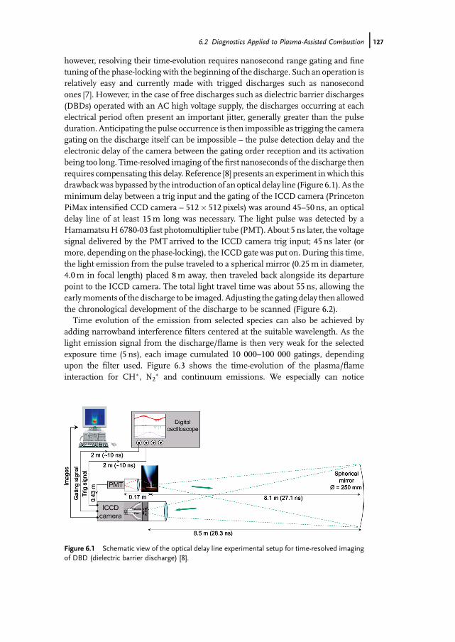
however, resolving their time-evolution requires nanosecond range gating and finetuning of the phase-lockingwith the beginning of the discharge. Such an operation isrelatively easy and currently made with trigged discharges such as nanosecondones [7]. However, in the case of free discharges such as dielectric barrier discharges(DBDs) operated with an AC high voltage supply, the discharges occurring at eachelectrical period often present an important jitter, generally greater than the pulseduration. Anticipating the pulse occurrence is then impossible as trigging the cameragating on the discharge itself can be impossible – the pulse detection delay and theelectronic delay of the camera between the gating order reception and its activationbeing too long. Time-resolved imaging of the first nanoseconds of the discharge thenrequires compensating this delay. Reference [8] presents an experiment in which thisdrawbackwas bypassed by the introduction of an optical delay line (Figure 6.1). As theminimum delay between a trig input and the gating of the ICCD camera (PrincetonPiMax intensified CCD camera – 512� 512 pixels) was around 45–50 ns, an opticaldelay line of at least 15m long was necessary. The light pulse was detected by aHamamatsuH 6780-03 fast photomultiplier tube (PMT). About 5 ns later, the voltagesignal delivered by the PMT arrived to the ICCD camera trig input; 45 ns later (ormore, depending on the phase-locking), the ICCD gate was put on. During this time,the light emission from the pulse traveled to a spherical mirror (0.25m in diameter,4.0m in focal length) placed 8m away, then traveled back alongside its departurepoint to the ICCD camera. The total light travel time was about 55 ns, allowing theearlymoments of the discharge to be imaged. Adjusting the gating delay then allowedthe chronological development of the discharge to be scanned (Figure 6.2).
Time evolution of the emission from selected species can also be achieved byadding narrowband interference filters centered at the suitable wavelength. As thelight emission signal from the discharge/flame is then very weak for the selectedexposure time (5 ns), each image cumulated 10 000–100 000 gatings, dependingupon the filter used. Figure 6.3 shows the time-evolution of the plasma/flameinteraction for CH�, N2
� and continuum emissions. We especially can notice
Figure 6.1 Schematic view of the optical delay line experimental setup for time-resolved imagingof DBD (dielectric barrier discharge) [8].
6.2 Diagnostics Applied to Plasma-Assisted Combustion j127

different characteristic times for CH� and N2� emissions, and an emission contin-
uum over 470 nm. Of course, prior knowledge of the emission wavelength for thesespecies is required; it can be determined by optical spectroscopy (Section 6.2.4).
We consider narrowband filtered imaging as a preliminary diagnostic tool that iseasy to operate and provides substantial information on the plasma/flame interactionat a relatively low-cost.
6.2.2Schlieren Flow Visualization
As mentioned in a book by Settles [9], Schlieren flow visualization is based on thedeflection of light caused by a refractive index gradient, which is directly related toflow density gradient. The deflected light is compared to undeflected light at aviewing screen. The undisturbed light is partially blocked by a knife edge. The lightthat is deflected toward or away from the knife edge produces a shadow patterndepending upon whether it was previously blocked or unblocked. This shadowpattern is a light-intensity representation of the expansions (low density regions) andcompressions (high density regions) that characterize the flow.
Figure 6.3 Time-resolved imaging of the plasma/flame interaction through broadband (>470 nm)and narrow-band (N*
2 and CH�) interference filters; image size¼ 35� 32mm2 [8].
Figure 6.2 Short exposure imaging of streamers and their interaction with a methane diffusionflame obtained using the setup represented in Figure 6.1 [8].
128j 6 Combustion Enhancement and Stabilization: Principles of Plasma Assistance
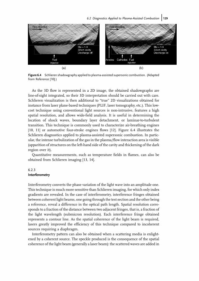
As the 3D flow is represented in a 2D image, the obtained shadowgraphs areline-of-sight integrated, so their 3D interpretation should be carried out with care.Schlieren visualization is then additional to �true� 2D visualizations obtained forinstance from laser plane-based techniques (PLIF, laser tomography, etc.). This low-cost technique using conventional light sources is non-intrusive, features a highspatial resolution, and allows wide-field analysis. It is useful in determining thelocation of shock waves, boundary layer detachment, or laminar-to-turbulenttransition. This technique is commonly used to characterize air-breathing engines[10, 11] or automotive four-stroke engines flows [12]. Figure 6.4 illustrates theSchlieren diagnostics applied to plasma-assisted supersonic combustion. In partic-ular, the intense turbulization of the gas in the plasma/flow interaction area is visible(apparition of structures on the left-hand side of the cavity and thickening of the darkregion over it).
Quantitative measurements, such as temperature fields in flames, can also beobtained from Schlieren imaging [13, 14].
6.2.3Interferometry
Interferometry converts the phase variation of the light wave into an amplitude one.This technique ismuchmore sensitive than Schlieren imaging, for which only indexgradients are revealed. In the case of interferometry, interference fringes obtainedbetween coherent light beams, one going through the test section and the other beinga reference, reveal a difference in the optical path length. Spatial resolution corre-sponds to a fraction of the distance between two adjacent fringes, that is, a fraction ofthe light wavelength (submicron resolution). Each interference fringe obtainedrepresents a contour line. As the spatial coherence of the light beam is required,lasers greatly improved the efficiency of this technique compared to incoherentsources requiring a diaphragm.
Interferometry pattern can also be obtained when a scattering media is enlight-ened by a coherent source. The speckle produced is the consequence of the spatialcoherence of the light beam (generally a laser beam): the scatteredwaves are added in
Figure 6.4 Schlieren shadowgraphy applied to plasma-assisted supersonic combustion. (Adaptedfrom Reference [10].)
6.2 Diagnostics Applied to Plasma-Assisted Combustion j129
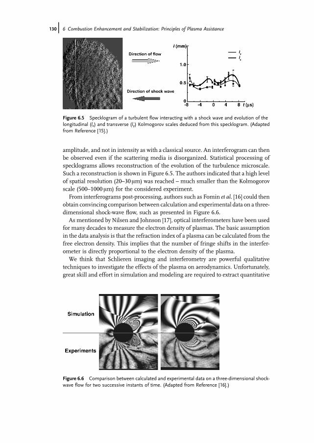
amplitude, and not in intensity as with a classical source. An interferogram can thenbe observed even if the scattering media is disorganized. Statistical processing ofspecklograms allows reconstruction of the evolution of the turbulence microscale.Such a reconstruction is shown in Figure 6.5. The authors indicated that a high levelof spatial resolution (20–30mm) was reached – much smaller than the Kolmogorovscale (500–1000mm) for the considered experiment.
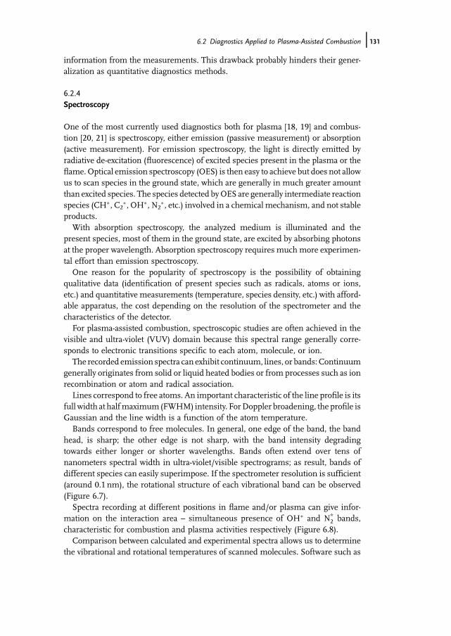
From interferograms post-processing, authors such as Fomin et al. [16] could thenobtain convincing comparison between calculation and experimental data on a three-dimensional shock-wave flow, such as presented in Figure 6.6.
As mentioned by Nilsen and Johnson [17], optical interferometers have been usedfor many decades to measure the electron density of plasmas. The basic assumptionin the data analysis is that the refraction index of a plasma can be calculated from thefree electron density. This implies that the number of fringe shifts in the interfer-ometer is directly proportional to the electron density of the plasma.
We think that Schlieren imaging and interferometry are powerful qualitativetechniques to investigate the effects of the plasma on aerodynamics. Unfortunately,great skill and effort in simulation and modeling are required to extract quantitative
Figure 6.6 Comparison between calculated and experimental data on a three-dimensional shock-wave flow for two successive instants of time. (Adapted from Reference [16].)
Figure 6.5 Specklogram of a turbulent flow interacting with a shock wave and evolution of thelongitudinal (lx) and transverse (ly) Kolmogorov scales deduced from this specklogram. (Adaptedfrom Reference [15].)
130j 6 Combustion Enhancement and Stabilization: Principles of Plasma Assistance
information from the measurements. This drawback probably hinders their gener-alization as quantitative diagnostics methods.
6.2.4Spectroscopy
One of the most currently used diagnostics both for plasma [18, 19] and combus-tion [20, 21] is spectroscopy, either emission (passive measurement) or absorption(active measurement). For emission spectroscopy, the light is directly emitted byradiative de-excitation (fluorescence) of excited species present in the plasma or theflame. Optical emission spectroscopy (OES) is then easy to achieve but does not allowus to scan species in the ground state, which are generally in much greater amountthan excited species. The species detected byOES are generally intermediate reactionspecies (CH�, C2
�, OH�, N2�, etc.) involved in a chemical mechanism, and not stable
products.With absorption spectroscopy, the analyzed medium is illuminated and the
present species, most of them in the ground state, are excited by absorbing photonsat the proper wavelength. Absorption spectroscopy requires much more experimen-tal effort than emission spectroscopy.
One reason for the popularity of spectroscopy is the possibility of obtainingqualitative data (identification of present species such as radicals, atoms or ions,etc.) and quantitative measurements (temperature, species density, etc.) with afford-able apparatus, the cost depending on the resolution of the spectrometer and thecharacteristics of the detector.
For plasma-assisted combustion, spectroscopic studies are often achieved in thevisible and ultra-violet (VUV) domain because this spectral range generally corre-sponds to electronic transitions specific to each atom, molecule, or ion.
The recorded emission spectra can exhibit continuum, lines, or bands: Continuumgenerally originates from solid or liquid heated bodies or from processes such as ionrecombination or atom and radical association.
Lines correspond to free atoms. An important characteristic of the line profile is itsfull width at halfmaximum(FWHM) intensity. ForDoppler broadening, the profile isGaussian and the line width is a function of the atom temperature.
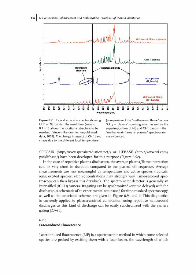
Bands correspond to free molecules. In general, one edge of the band, the bandhead, is sharp; the other edge is not sharp, with the band intensity degradingtowards either longer or shorter wavelengths. Bands often extend over tens ofnanometers spectral width in ultra-violet/visible spectrograms; as result, bands ofdifferent species can easily superimpose. If the spectrometer resolution is sufficient(around 0.1 nm), the rotational structure of each vibrational band can be observed(Figure 6.7).
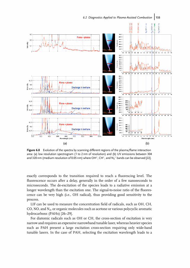
Spectra recording at different positions in flame and/or plasma can give infor-mation on the interaction area – simultaneous presence of OH� and N*
2 bands,characteristic for combustion and plasma activities respectively (Figure 6.8).
Comparison between calculated and experimental spectra allows us to determinethe vibrational and rotational temperatures of scanned molecules. Software such as
6.2 Diagnostics Applied to Plasma-Assisted Combustion j131
SPECAIR (http://www.specair-radiation.net/) or LIFBASE (http://www.sri.com/psd/lifbase/) have been developed for this purpose (Figure 6.9c).
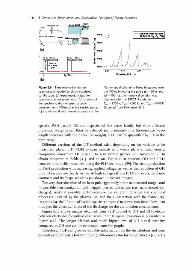
In the case of repetitive plasma discharges, the average plasma/flame interactioncan be very short in duration compared to the plasma off sequence. Averagemeasurements are less meaningful as temperature and active species (radicals,ions, excited species, etc.) concentrations may strongly vary. Time-resolved spec-troscopy can then bypass this drawback. The spectrometer detector is generally anintensified (ICCD) camera. Its gating can be synchronized (or time delayed) with thedischarge. A schematic of an experimental setup used for time-resolved spectroscopy,as well as the associated scheme, are given in Figure 6.9a and b. This diagnosticsis currently applied to plasma-assisted combustion using repetitive nanoseconddischarges as this kind of discharge can be easily synchronized with the cameragating [23–25].
6.2.5Laser-Induced Fluorescence
Laser-induced fluorescence (LIF) is a spectroscopic method in which some selectedspecies are probed by exciting them with a laser beam, the wavelength of which
Figure 6.7 Typical emission spectra showingCH� or N*
2 bands. The resolution (around0.1 nm) allows the rotational structure to beresolved (Vincent-Randonnier, unpublisheddata, 2009). The change in aspect of CH� bandshape due to the different local temperature
(comparison of the �methane–air flame� versus�CH4 þ plasma� spectrograms), as well as thesuperimposition of N*
2 and CH� bands in the�methane–air flame þ plasma� spectrogram,are evidenced.
132j 6 Combustion Enhancement and Stabilization: Principles of Plasma Assistance
exactly corresponds to the transition required to reach a fluorescing level. Thefluorescence occurs after a delay, generally in the order of a few nanoseconds tomicroseconds. The de-excitation of the species leads to a radiative emission at alonger wavelength than the excitation one. The signal-to-noise ratio of the fluores-cence can be very high (i.e., OH radical), thus providing good sensitivity to theprocess.
LIF can be used to measure the concentration field of radicals, such as OH, CH,CO, NO, and N2, or organicmolecules such as acetone or various polycyclic aromatichydrocarbons (PAHs) [26–29].
For diatomic radicals such as OH or CH, the cross-section of excitation is verynarrow and requires an expensive narrowband tunable laser, whereas heavier speciessuch as PAH present a large excitation cross-section requiring only wide-bandtunable lasers. In the case of PAH, selecting the excitation wavelength leads to a
Figure 6.8 Evolution of the spectra by scanning different regions of the plasma/flame interactionarea: (a) low resolution spectrogram (1 to 2 nm of resolution) and (b) UV emissions between 304and 320nm (medium resolution of 0.05 nm) where OH�, CH�, and N2
� bands can be observed [22].
6.2 Diagnostics Applied to Plasma-Assisted Combustion j133
specific PAH family. Different species of the same family, but with differentmolecular weights, can then be detected simultaneously (the fluorescence wave-length increases with the molecular weight). PAH can be quantified by LIF in theppm range.
Different versions of the LIF method exist, depending on the variable to bemeasured: planar LIF (PLIF) to scan radicals in a whole plane simultaneously,two-photon absorption LIF (TALIF) to scan atomic species [30], two-color LIF toobtain temperature fields [31], and so on. Figure 6.10 presents OH and PAHconcentration fields measured using the PLIF technique [29]. The strong reductionin PAH production with increasing applied voltage, as well as the reduction of OHproduction area are clearly visible. At high voltages (from 10 kV and over), the flamecontracts and its shape wrinkles (as shown in instant images).
The very short duration of the laser pulse (generally in the nanosecond range), andits possible synchronization with trigged plasma discharges (i.e., nanosecond dis-charges), make it possible to time-resolve the different physical and chemicalprocesses initiated by the plasma [28] and their interaction with the flame [26].In particular, the lifetime of excited species compared to convection time allow us tointerpret the chemical effect of the discharge on the combustion mechanisms.
Figure 6.11 shows images obtained from PLIF applied to OH and CH radicalsbetween electrodes for pulsed discharges; their temporal evolution is presented inFigure 6.12. The longer lifetime and much higher level of OH signal intensitycompared to CH one can be evidenced from the graphs.
Therefore, PLIF can provide valuable information on the distribution and con-centration of radicals. However, the signal-to-noise ratio for some radicals (i.e., CH)
Figure 6.9 Time-resolved emissionspectroscopy applied to plasma-assistedcombustion: (a) experimental setup forspectroscopic measurements; (b) strategy ofthe synchronization of spectroscopicmeasurements 100 ns after the electric pulse;(c) experimental and numerical spectra of the
filamentary discharge in flame integrated overthe 100 ns following the pulse (t0¼ 60 ns andDt¼ 100 ns); the numerical solution wasobtained with the SPECAIR code forTrot¼ 2700 K, Tvib¼ 4000 K, and Telec¼ 8400 K.(Adapted from Reference [23].)
134j 6 Combustion Enhancement and Stabilization: Principles of Plasma Assistance
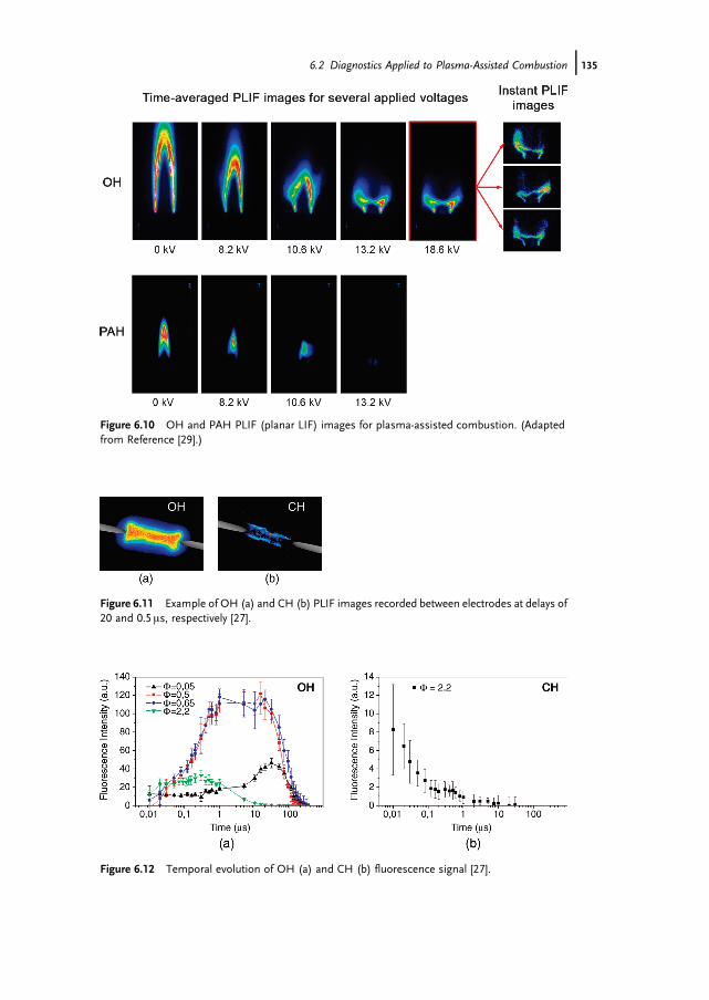
Figure 6.11 Example of OH (a) and CH (b) PLIF images recorded between electrodes at delays of20 and 0.5ms, respectively [27].
Figure 6.10 OH and PAH PLIF (planar LIF) images for plasma-assisted combustion. (Adaptedfrom Reference [29].)
Figure 6.12 Temporal evolution of OH (a) and CH (b) fluorescence signal [27].
6.2 Diagnostics Applied to Plasma-Assisted Combustion j135
can be very low; skill and effort are then required for data processing leading tosatisfying results. This explainswhyOH-PLIF ismuchmore common thanCH–PLIFanalysis. Nevertheless, CH is a much more reliable tracer of the reactional activity inthe flame front than OH, which quickly diffuses out of the reaction zone and whoselonger lifetime in the excited state is not negligible with respect to convective time.
6.2.6Coherent anti-Stokes Raman Scattering Thermometry
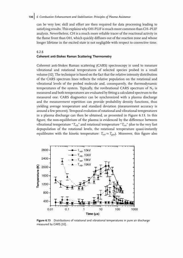
Coherent anti-Stokes Raman scattering (CARS) spectroscopy is used to measurevibrational and rotational temperatures of selected species probed in a smallvolume [32]. The technique is based on the fact that the relative intensity distributionof the CARS spectrum lines reflects the relative population on the rotational andvibrational levels of the probed molecule and, consequently, the thermodynamictemperatures of the system. Typically, the rovibrational CARS spectrum of N2 ismeasured and both temperatures are evaluated by fitting a calculated spectrum to themeasured one. CARS diagnostics can be synchronized with a plasma dischargeand the measurement repetition can provide probability density functions, thusyielding average temperature and standard deviation (measurement accuracy isaround a few percent). Temporal evolution of rotational and vibrational temperaturesin a plasma discharge can then be obtained, as presented in Figure 6.13. In thisfigure, the non-equilibrium of the plasma is evidenced by the difference betweenvibrational temperature �Tvib� and rotational temperature �Trot� (due to the very fastdepopulation of the rotational levels, the rotational temperature quasi-instantlyequilibrates with the kinetic temperature: Trot�Tgas). Moreover, this figure also
Figure 6.13 Distributions of rotational and vibrational temperatures in pure air dischargemeasured by CARS [32].
136j 6 Combustion Enhancement and Stabilization: Principles of Plasma Assistance
shows a non-monotonic temporal evolution of temperature (the temperature in-crease between 1 and 100 ms is not clearly understood).
6.2.7Thomson Scattering
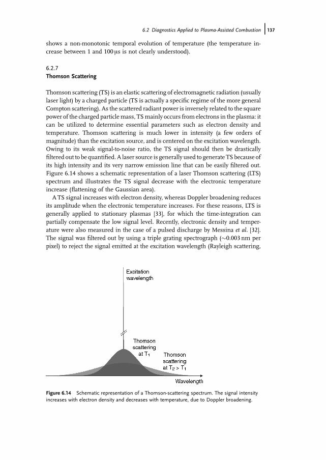
Thomson scattering (TS) is an elastic scattering of electromagnetic radiation (usuallylaser light) by a charged particle (TS is actually a specific regime of the more generalCompton scattering). As the scattered radiant power is inversely related to the squarepower of the charged particlemass, TSmainly occurs from electrons in the plasma: itcan be utilized to determine essential parameters such as electron density andtemperature. Thomson scattering is much lower in intensity (a few orders ofmagnitude) than the excitation source, and is centered on the excitation wavelength.Owing to its weak signal-to-noise ratio, the TS signal should then be drasticallyfiltered out to be quantified. A laser source is generally used to generate TS because ofits high intensity and its very narrow emission line that can be easily filtered out.Figure 6.14 shows a schematic representation of a laser Thomson scattering (LTS)spectrum and illustrates the TS signal decrease with the electronic temperatureincrease (flattening of the Gaussian area).
ATS signal increases with electron density, whereas Doppler broadening reducesits amplitude when the electronic temperature increases. For these reasons, LTS isgenerally applied to stationary plasmas [33], for which the time-integration canpartially compensate the low signal level. Recently, electronic density and temper-ature were also measured in the case of a pulsed discharge by Messina et al. [32].The signal was filtered out by using a triple grating spectrograph (�0.003 nm perpixel) to reject the signal emitted at the excitation wavelength (Rayleigh scattering,
Figure 6.14 Schematic representation of a Thomson-scattering spectrum. The signal intensityincreases with electron density and decreases with temperature, due to Doppler broadening.
6.2 Diagnostics Applied to Plasma-Assisted Combustion j137
Mie scattering, and stray light). The laser pulse had to be limited to a low level(10mJ per pulse) to avoid measurement perturbations. The probed volume was1mm long and 100 mm in diameter and the electronic density and temperature couldbe measured over 1015–1020m�3 and below 50 000–70 000K, respectively.
6.2.8Gas Chromatography
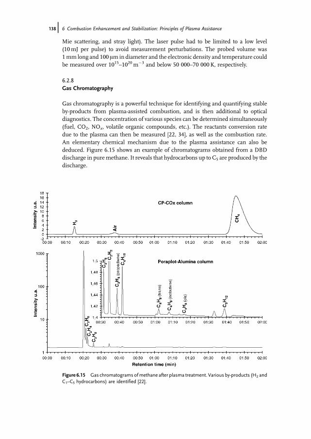
Gas chromatography is a powerful technique for identifying and quantifying stableby-products from plasma-assisted combustion, and is then additional to opticaldiagnostics. The concentration of various species can be determined simultaneously(fuel, CO2, NOx, volatile organic compounds, etc.). The reactants conversion ratedue to the plasma can then be measured [22, 34], as well as the combustion rate.An elementary chemical mechanism due to the plasma assistance can also bededuced. Figure 6.15 shows an example of chromatograms obtained from a DBDdischarge in puremethane. It reveals that hydrocarbons up to C5 are produced by thedischarge.
Figure 6.15 Gas chromatograms ofmethane after plasma treatment. Various by-products (H2 andC1–C5 hydrocarbons) are identified [22].
138j 6 Combustion Enhancement and Stabilization: Principles of Plasma Assistance
Table 6.1 gathers concentration measurements of the main by-products: it in-dicates that the concentration of hydrocarbons produced decreases the more carbonatoms they contain. For a given number of carbon atoms in a molecule, theconcentration decreases with the unsaturation (C�C>C¼C>C:C).
If the gas chromatograph is coupled to a mass spectrometer detector, extrainformation on reactional mechanisms can be determined by substituting a reactantwith its isotope. Identification and quantification of this isotope in the by-productscan indeed allow us to distinguish the preferential pathway [35].
Gas chromatography is a very powerful tool, allowing identification and quanti-fication of various pollutant species currently ignored by optical diagnostics butpresent in combustion or plasma processes. We consider that gas chromatographyshould be used more often to quantify the combustion by-products and provideboundary conditions to test and validate the kinetics used in plasma-assistedcombustion computed simulations.
6.3Effect of the Plasma Assistance on Combustion
6.3.1General Considerations
In a recent review, Starikovskaia [36] mentioned that plasma systems may be ofsignificant benefit for the ignition of fuel–air mixtures at moderate gas densitiesand high-velocity gas flows (including supersonic flows), for combustion assistedby plasma at atmospheric pressure, or for lean premixed combustion stimulation.Variousplasmatechniquesusedto improveignitionand/orcombustionareproposed:coronas, streamers,DBD, atmospheric pressure glowdischarges, pulsednanoseconddischarges, and radio-frequency (RF) or microwave (MW) discharges. Table 6.2summarizes the characteristic parameters of such plasmas. Specific informationon ignition can be found in Chapter 5 by Phuoc (laser ignition) and Chapter 3 by Dasand Thynell (corona ignition), whereas reviews by Starikovskaia [36] and Fridmanet al. [37] present descriptions and characteristics of the main plasma discharges.
The applied voltages can strongly vary depending on the kind of plasma selected.Higher voltages are associated with specific difficulties in isolating the electricalcircuit to avoid �parasitic� discharges.
High frequency (RF, MW) or fast current rise-time discharges (for ultrashortdischarges) also produces intense electromagnetic (EM) emissions that can be aproblem (i.e., EM compatibility of airborne systems).
The electronic temperature is another important parameter as it leads to theproduction of reactive species (ions, radicals, etc.) by electronic impact on the gasmolecules. Generally, it ranges from 1 to 10 eV (1 eV corresponds to 11 600K) forplasma-assisted combustion applications. The concentration level of the differentby-products of the plasma discharges depends on the electron energy distributionfunction (EEDF) and the molecules reaction cross-sections. Plasma chemistry then
6.3 Effect of the Plasma Assistance on Combustion j139
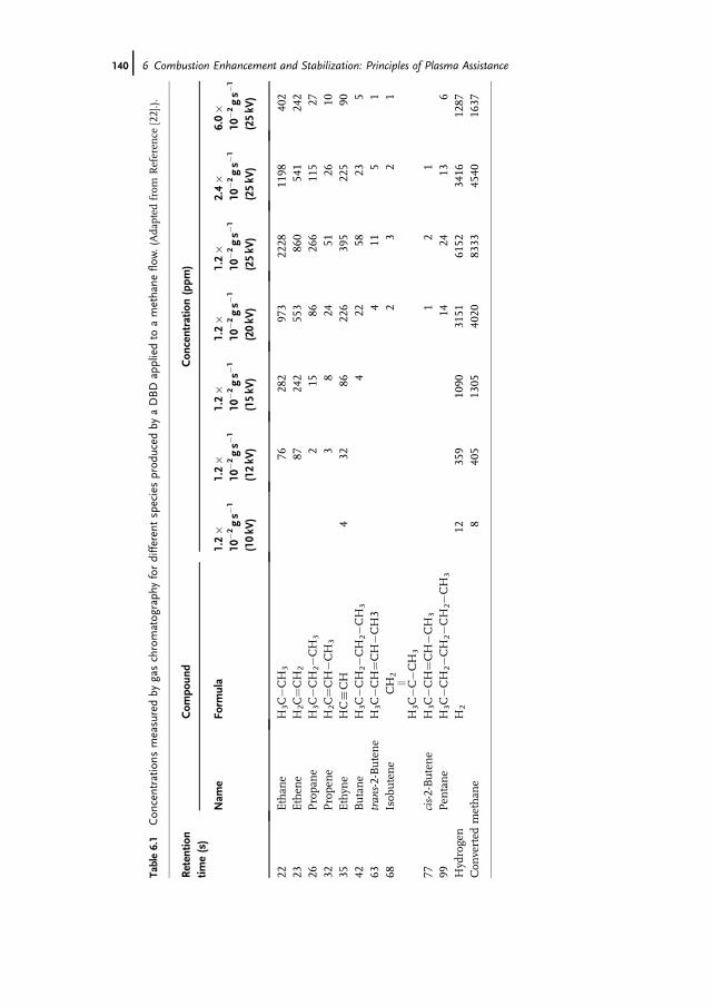
Table6.1
Con
centratio
nsmeasuredby
gaschromatog
raph
yfordifferen
tspeciesprod
uced
byaDBDap
pliedto
amethane
flow.(Adapted
from
Referen
ce[22].).
Retentio
ntim
e(s)
Com
poun
dCon
centratio
n(ppm
)
Nam
eFo
rmula
1.2�
10�2gs�
1
(10kV
)
1.2�
10�2gs�
1
(12kV
)
1.2�
10�2gs�
1
(15kV
)
1.2�
10�2gs�
1
(20kV
)
1.2�
10�2gs�
1
(25kV
)
2.4�
10�2gs�
1
(25kV
)
6.0�
10�2gs�
1
(25kV
)
22Ethan
eH
3C�C
H3
7628
297
322
2811
9840
223
Ethen
eH
2C¼C
H2
8724
255
386
054
124
226
Propane
H3C
�CH
2�C
H3
215
8626
611
527
32Propene
H2C
¼CH�C
H3
38
2451
2610
35Ethyn
eHC:CH
432
8622
639
522
590
42Butane
H3C
�CH
2�C
H2�C
H3
422
5823
563
tran
s-2-Butene
H3C
�CH¼C
H�C
H3
411
51
68Isob
utene
CH
2jj
H3C
�C�C
H3
23
21
77cis-2-Butene
H3C
�CH¼C
H�C
H3
12
199
Pen
tane
H3C
�CH
2�C
H2�C
H2�
CH
314
2413
6Hydrogen
H2
1235
910
9031
5161
5234
1612
87Con
verted
methan
e8
405
1305
4020
8333
4540
1637
140j 6 Combustion Enhancement and Stabilization: Principles of Plasma Assistance
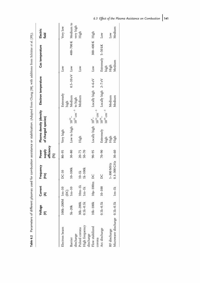
Table6.2
Parametersof
differen
tplasmas
used
forcombu
stionassistan
ceor
stabilizatio
n.(Adapted
from
Chan
g[38],w
ithaddition
sfrom
Sch€ utzeetal.[39].).
Voltage
(V)
Current
(A)
Frequency
(Hz)
Power
supp
lyefficiency
(%)
Plasmadensity
(density
ofchargedspecies)
Electron
temperature
Gas
temperature
Electric
field
Electronbeam
100k–20
0M1m
–10
(DC)
DC-10
80–95
Veryhigh
Extremely
high
Low
Verylow
Barrier
discharge
5k–20
k1m
–10
10–10
0k30–80
Lowto
high
1012–
1015cm
�3
Medium
tohigh
0.5–10
eVLo
w40
0–70
0K
Medium
tovery
high
Pulsedcorona
30k–20
0k10
m–1k
10–1k
20–75
High
Medium
Low
High
Highfrequen
cydischarge
0.1k–0.5k
1m–1k
1k–10
0k50–70
Flowstabilized
corona
10k–10
0k10m–10
0mDC
90–95
Locally
high
109 –
1013cm
�3
Locally
high
4–6eV
Low
300–40
0K
High
Arc
discharge
0.1k–0.5k
10–10
0DC
70–90
Extremely
high
1016–
1019cm
�3
Locally
high
2–7eV
Extremely
high
5–50
kKLo
w
RFdischarge
1–30
0MHz
High
Medium
High
Low
Microwavedischarge
0.1k–0.5k
1m–1k
0.3–30
0GHz
30–60
High
Medium
Medium
Medium
6.3 Effect of the Plasma Assistance on Combustion j141
directly depends on the electronic temperature. For higher electronic temperatures,some unwanted effects can also occur, such as significant NOx production, due to thecreation of N2 in triplet state (A3Sþ
u , B3Pg, and C3Pu), which reacts with oxygenmolecules (nitriding reactions).
6.3.2Experiments and Interpretations
This section is organized in three parts. The first focuses on plasma assistanceapplied to non- or partially-premixed combustion, the second on premixed combus-tion, and the third on the more specific supersonic combustion.
The reason for separate consideration of premixed and non-premixed combustionis justified by fundamental differences between premixed and diffusion flame.As they are of prime importance on the plasma assistance strategy, we will brieflyrecall them.
A premixed flame is characterized by a fundamental parameter: the normal flamevelocity with respect of the unburned flow. Normal flame velocity is a physicalconstant for eachmixture. The premixed flame can be viewed as an �active object� inthe sense that it is able to resist the flow velocity if the normal velocity is higher.Notably, in premixed combustion the flame separates combustion products andunburned gas.
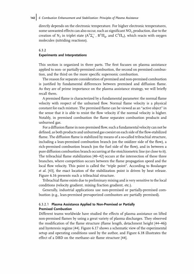
For a diffusionflame in non-premixed flow, such a fundamental velocity can not bedefined, as both products andunburned gas coexist on each side of theflow-stabilizedflame. The diffusion flame is stabilized by means of a so-called tribrachial structure,including a lean-premixed combustion branch (on the oxidizer side of the flow), arich-premixed combustion branch (on the fuel side of the flow), and in between apure diffusion combustion branch occurring at the stoichiometric line (or close to it).The tribrachial flame stabilization [40–42] occurs at the intersection of these threebranches, where competition occurs between the flame propagation speed and thelocal flow velocity. This point is called the �triple point�. According to Boulangeret al. [43], the exact location of the stabilization point is driven by heat release.Figure 6.16 presents such a tribrachial structure.
Tribrachial flame exists due to preliminary mixing and is very sensitive to the localconditions (velocity gradient, mixing fraction gradient, etc.).
Generally, industrial applications use non-premixed or partially-premixed com-bustion (e.g., lean-premixed prevaporized combustors are partially premixed).
6.3.2.1 Plasma Assistance Applied to Non-Premixed or PartiallyPremixed CombustionDifferent teams worldwide have studied the effects of plasma assistance on liftednon-premixed flames by using a great variety of plasma discharges. They observedthe modification of the flame structure (flame length, detachment height [44–46])and hysteresis regime [44]. Figure 6.17 shows a schematic view of the experimentalsetup and operating conditions used by the author, and Figure 6.18 illustrates theeffect of a DBD on the methane–air flame structure [44].
142j 6 Combustion Enhancement and Stabilization: Principles of Plasma Assistance
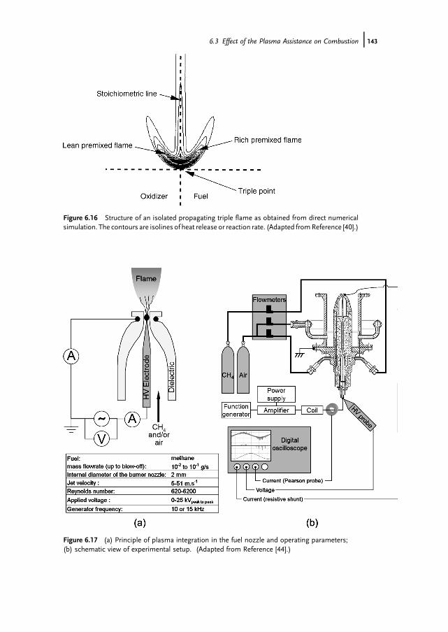
Figure 6.17 (a) Principle of plasma integration in the fuel nozzle and operating parameters;(b) schematic view of experimental setup. (Adapted from Reference [44].)
Figure 6.16 Structure of an isolated propagating triple flame as obtained from direct numericalsimulation. The contours are isolines of heat release or reaction rate. (Adapted fromReference [40].)
6.3 Effect of the Plasma Assistance on Combustion j143
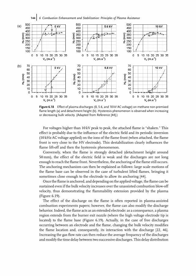
For voltages higher than 10 kV peak to peak, the attached flame is �shaken.� Thiseffect is probably due to the influence of the electric field and its periodic inversion(10 kHzAC voltage applied) on the ions of the flame front (when attached, the flamefront is very close to the HV electrode). This destabilization clearly influences theflame lift-off and then the hysteresis phenomenon.
Conversely, when the flame is strongly detached (detachment height around50mm), the effect of the electric field is weak and the discharges are not longenough to reach the flame front. Nevertheless, the anchoring of theflame still occurs.The anchoring mechanism can then be explained as follows: large scale motions ofthe flame base can be observed in the case of turbulent lifted flames, bringing itsometimes close enough to the electrode to allow its anchoring [44].
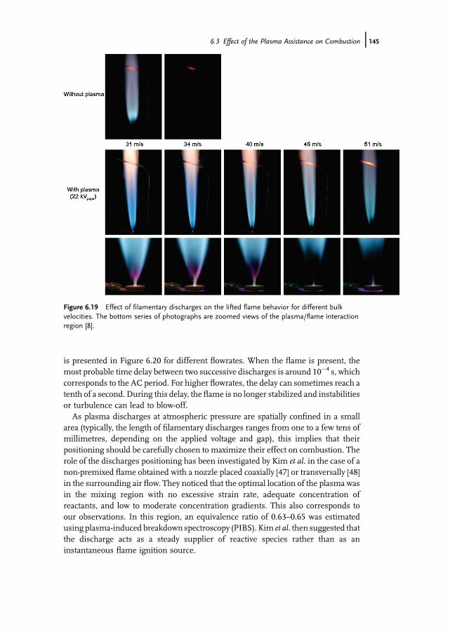
Once theflame is anchored, anddepending on the applied voltage, theflame canbesustained even if the bulk velocity increases over the unassisted combustion blow-offvelocity, thus demonstrating the flammability extension provided by the plasma(Figure 6.19).
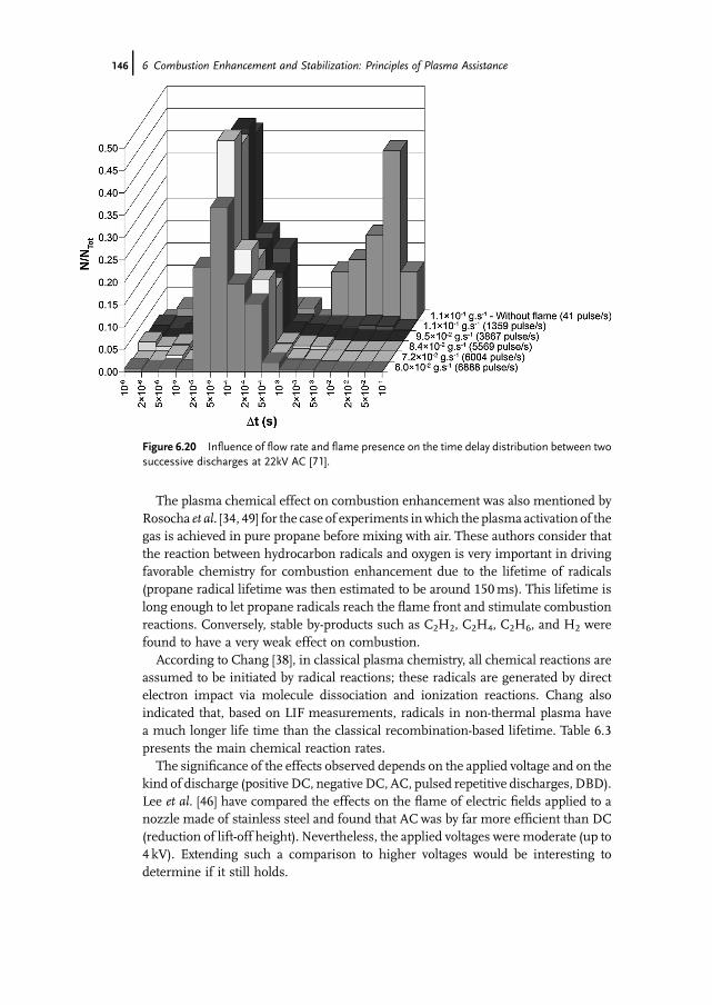
The effect of the discharge on the flame is often reported in plasma-assistedcombustion experiments papers; however, the flame can also modify the dischargebehavior. Indeed, the flame acts as an extended electrode: as a consequence, a plasmaregion extends from the burner exit nozzle (where the high voltage electrode tip islocated) to the flame base (Figure 6.19). Actually, in the case of free dischargesoccurring between an electrode and the flame, changing the bulk velocity modifiesthe flame location and, consequently, its interaction with the discharge [22, 46].Increasing the gas flow rate can then reduce the average frequency of the dischargesandmodify the time delay between two successive discharges. This delay distribution
Figure 6.18 Effect of plasma discharges (0, 5.6, and 10 kV AC voltage) on methane non-premixedflame length (a) and detachment height (b). Hysteresis phenomenon is observed when increasingor decreasing bulk velocity. (Adapted from Reference [44].)
144j 6 Combustion Enhancement and Stabilization: Principles of Plasma Assistance
is presented in Figure 6.20 for different flowrates. When the flame is present, themost probable time delay between two successive discharges is around 10�4 s, whichcorresponds to the AC period. For higher flowrates, the delay can sometimes reach atenth of a second. During this delay, the flame is no longer stabilized and instabilitiesor turbulence can lead to blow-off.
As plasma discharges at atmospheric pressure are spatially confined in a smallarea (typically, the length of filamentary discharges ranges from one to a few tens ofmillimetres, depending on the applied voltage and gap), this implies that theirpositioning should be carefully chosen to maximize their effect on combustion. Therole of the discharges positioning has been investigated by Kim et al. in the case of anon-premixed flame obtained with a nozzle placed coaxially [47] or transversally [48]in the surrounding air flow. They noticed that the optimal location of the plasma wasin the mixing region with no excessive strain rate, adequate concentration ofreactants, and low to moderate concentration gradients. This also corresponds toour observations. In this region, an equivalence ratio of 0.63–0.65 was estimatedusing plasma-induced breakdown spectroscopy (PIBS). Kim et al. then suggested thatthe discharge acts as a steady supplier of reactive species rather than as aninstantaneous flame ignition source.
Figure 6.19 Effect of filamentary discharges on the lifted flame behavior for different bulkvelocities. The bottom series of photographs are zoomed views of the plasma/flame interactionregion [8].
6.3 Effect of the Plasma Assistance on Combustion j145
The plasma chemical effect on combustion enhancement was also mentioned byRosocha et al. [34, 49] for the case of experiments inwhich the plasma activation of thegas is achieved in pure propane before mixing with air. These authors consider thatthe reaction between hydrocarbon radicals and oxygen is very important in drivingfavorable chemistry for combustion enhancement due to the lifetime of radicals(propane radical lifetime was then estimated to be around 150ms). This lifetime islong enough to let propane radicals reach the flame front and stimulate combustionreactions. Conversely, stable by-products such as C2H2, C2H4, C2H6, and H2 werefound to have a very weak effect on combustion.
According to Chang [38], in classical plasma chemistry, all chemical reactions areassumed to be initiated by radical reactions; these radicals are generated by directelectron impact via molecule dissociation and ionization reactions. Chang alsoindicated that, based on LIF measurements, radicals in non-thermal plasma havea much longer life time than the classical recombination-based lifetime. Table 6.3presents the main chemical reaction rates.
The significance of the effects observed depends on the applied voltage and on thekind of discharge (positive DC, negative DC, AC, pulsed repetitive discharges, DBD).Lee et al. [46] have compared the effects on the flame of electric fields applied to anozzle made of stainless steel and found that AC was by far more efficient than DC(reduction of lift-off height). Nevertheless, the applied voltages were moderate (up to4 kV). Extending such a comparison to higher voltages would be interesting todetermine if it still holds.
Figure 6.20 Influence of flow rate and flame presence on the time delay distribution between twosuccessive discharges at 22kV AC [71].
146j 6 Combustion Enhancement and Stabilization: Principles of Plasma Assistance
Kim et al. [47] have demonstrated that the single electrode corona discharge(SECD) increases the maximum bulk velocity by approximately 20–30%, versus50–100% for the DBD, in the case of a lifted non-premixed methane flamesurrounded by an air co-flow. With this kind of discharge, no significant effects onthe co-flow velocity stability limit were noticed, in contrast to ultra-short repetitivedischarges (USRD) with which a gain close to ten-fold was observed. According toCriner et al. [45], the dielectric barrier favors flame stabilization by extending theduration of the electrode electrostatic effect on flame ions.
6.3.2.2 Plasma Assistance Applied to Premixed CombustionStudying the effect of plasma on premixed combustion is of prime interest, especiallybecause a feature as fundamental as laminar flame velocity can be measured, thusproviding an intrinsic reference to quantitatively compare different plasmaconfigurations.
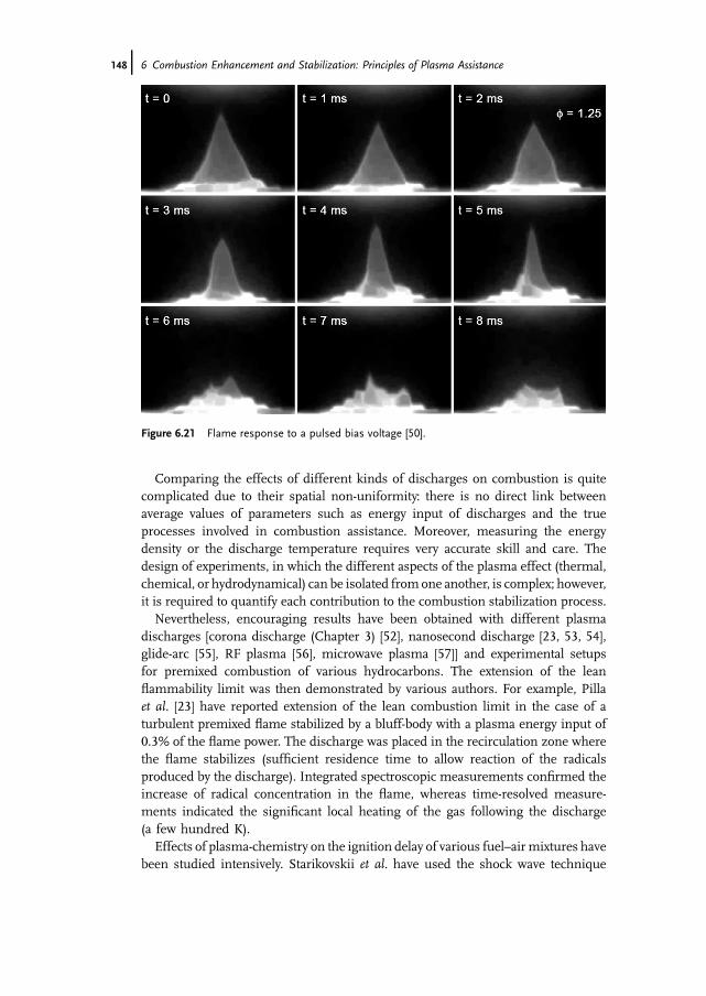
Unfortunately, in the case of laminar premixed flames, the aerodynamical per-turbations caused by the electric field (ionic wind) are not negligible compared to thelow flow velocity. The flame structure is then strongly disturbed (Figure 6.21). Theflame becomes unstable and measuring the flame velocity based upon its shape iscomplex.
ForMarcum andGanguly [50], the electric field forces the ions of the flame front todiffuse (lowering of the Lewis numbers of ionic species) where reactant concentra-tions differ significantly from those of laminar flow. The flame front geometrybecomes wrinkled. The authors of this study point out that this �electric pressureeffect� is similar to the flame front modification produced by changes in ambient airpressure.
Applying an electric field below breakdown is a way to lower its effect on thelaminar flame structure. This approach was used by Zaida et al. [51] to measure theincrease of flame velocity (up to þ 67%) under microwave stimulation using inputpowers up to 2600W. Even if only a fraction of this power is applied to theflame (a fewtens of watts), the energetic cost remains significant.
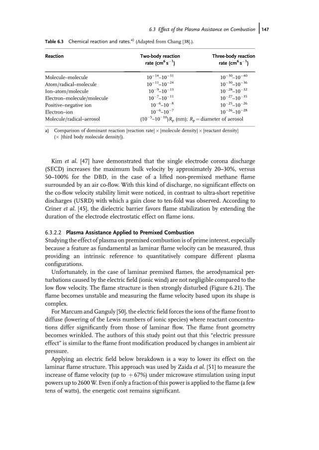
Table 6.3 Chemical reaction and rates.a) (Adapted from Chang [38].).
Reaction Two-body reactionrate (cm6 s�1)
Three-body reactionrate (cm6 s�1)
Molecule–molecule 10�14–10�31 10�30–10�40
Atom/radical–molecule 10�11–10�24 10�30–10�36
Ion–atom/molecule 10�9–10�13 10�28–10�32
Electron–molecule/molecule 10�7–10�11 10�27–10�35
Positive–negative ion 10�6–10�8 10�25–10�26
Electron–ion 10�6–10�7 10�26–10�28
Molecule/radical–aerosol (10�5–10�10)Rp (nm); Rp¼ diameter of aerosol
a) Comparison of dominant reaction [reaction rate]� [molecule density]� [reactant density](� [third body molecule density]).
6.3 Effect of the Plasma Assistance on Combustion j147
Comparing the effects of different kinds of discharges on combustion is quitecomplicated due to their spatial non-uniformity: there is no direct link betweenaverage values of parameters such as energy input of discharges and the trueprocesses involved in combustion assistance. Moreover, measuring the energydensity or the discharge temperature requires very accurate skill and care. Thedesign of experiments, in which the different aspects of the plasma effect (thermal,chemical, or hydrodynamical) can be isolated fromone another, is complex; however,it is required to quantify each contribution to the combustion stabilization process.
Nevertheless, encouraging results have been obtained with different plasmadischarges [corona discharge (Chapter 3) [52], nanosecond discharge [23, 53, 54],glide-arc [55], RF plasma [56], microwave plasma [57]] and experimental setupsfor premixed combustion of various hydrocarbons. The extension of the leanflammability limit was then demonstrated by various authors. For example, Pillaet al. [23] have reported extension of the lean combustion limit in the case of aturbulent premixed flame stabilized by a bluff-body with a plasma energy input of0.3% of the flame power. The discharge was placed in the recirculation zone wherethe flame stabilizes (sufficient residence time to allow reaction of the radicalsproduced by the discharge). Integrated spectroscopic measurements confirmed theincrease of radical concentration in the flame, whereas time-resolved measure-ments indicated the significant local heating of the gas following the discharge(a few hundred K).
Effects of plasma-chemistry on the ignition delay of various fuel–airmixtures havebeen studied intensively. Starikovskii et al. have used the shock wave technique
Figure 6.21 Flame response to a pulsed bias voltage [50].
148j 6 Combustion Enhancement and Stabilization: Principles of Plasma Assistance
coupled to nanosecond pulsed discharges to obtain spatially uniform fast ionizationwaves and investigate their effect on the ignition delay of hydrocarbon–air–argonmixtures. Ignition delay was measured for various temperatures or pressures [58]and kinetics of plasma ignition of hydrocarbon containing mixtures were pro-posed [59, 60].
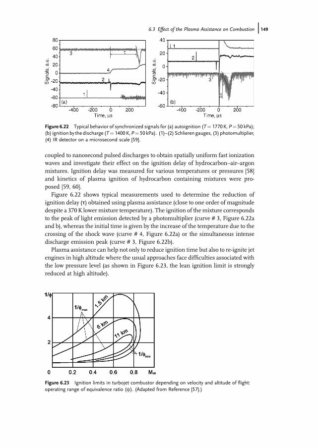
Figure 6.22 shows typical measurements used to determine the reduction ofignition delay (t) obtained using plasma assistance (close to one order of magnitudedespite a 370K lowermixture temperature). The ignition of themixture correspondsto the peak of light emission detected by a photomultiplier (curve # 3, Figure 6.22aand b), whereas the initial time is given by the increase of the temperature due to thecrossing of the shock wave (curve # 4, Figure 6.22a) or the simultaneous intensedischarge emission peak (curve # 3, Figure 6.22b).
Plasma assistance can help not only to reduce ignition time but also to re-ignite jetengines in high altitude where the usual approaches face difficulties associated withthe low pressure level (as shown in Figure 6.23, the lean ignition limit is stronglyreduced at high altitude).
Figure 6.23 Ignition limits in turbojet combustor depending on velocity and altitude of flight:operating range of equivalence ratio (w). (Adapted from Reference [57].)
Figure 6.22 Typical behavior of synchronized signals for (a) autoignition (T¼ 1770K, P¼ 50 kPa);(b) ignition by the discharge (T¼ 1400 K,P¼ 50 kPa). (1)–(2) Schlieren gauges, (3) photomultiplier,(4) IR detector on a microsecond scale [59].
6.3 Effect of the Plasma Assistance on Combustion j149
Ignition and flame stabilization for hydrocarbons–air mixtures could then beachieved under pulsed discharge assistance at low to intermediate pressure(6.7–26.6 kPa) [54], the flame originating in the plasma and extending downstream(90%of the fuel is then oxidized). The authors suggest the partial oxidation of the fuelat low temperature (�cold� combustion) is followed by a plasma temperature rise andthen true ignition of the combustion with heat generation.
As the efficiency of the process depends upon various parameters, optimizationmethods can be used to improve it. For example,Hammer et al. [55] have investigatedthe role of a miniaturized glide-arc reactor (input power up to 15W) to increase lean-premixed flame stability and optimized the chemical efficiency of their plasmareactor using Tagushi�s �Design of experiments� method (selection of the optimalparameters – discharge gap, fuel–air ratio, input power, and so on – from a limitednumber of experiments). They noticed a decrease of NOx emission with theoptimized process.
6.3.2.3 Plasma Assistance Applied to Supersonic CombustionScramjet effective operation in a wide range of flowMach numbers looks like one ofthe most technically difficult challenges for the design of hypersonic vehiclespowered by air-breathing engines. The most promising way is a scramjet propelledvehicle with a flexible gasdynamic configuration (including inlet, injection system,combustor, nozzle, rubber scramjet) depending on flightMach number and altitude.
Unfortunately, this approach cannot be supported properly due to technical issues:materials, gears, and so on. A common trade-off is to optimize the geometricalconfiguration for a chosen Mach number of operation, which leads to degradedperformance for both lower and higher Mach numbers.
The overall capability of scramjets with fixed geometry of the duct could beimproved using extra methods such as, for instance, staged fuel injection, additionalflame-holding at low temperature (including plasma), and a few others. The penaltyof such a philosophy is a rise of the total pressure losses and, consequently, a decreaseof specific impulse and thrust coefficient.
During the last decade, different research teams investigated the ability of plasmadischarges to expand the operational field of scramjet to off-design values of Machnumber at fixed geometry of gasdynamic duct [10, 61–63]. In particular, Leonovet al. [10, 61] have indicated that the plasma generation in the flow results not only inheat and active media production but also in the modification of supersonic flowstructure, including artificial separation, vorticity, etc. The plasma and the recircu-lation zone are interdependent, which leads to a self-adjustment loop: the plasmamodifies the chemistry, which in turn modifies the heat release, which in turnmodifies the recirculation zone location, which in turn modifies the plasma para-meters, and so on. This feedback is an important feature of active flame control byelectrical discharges. Leonov and Sabelnikov [64] suggested that in case of hydro-carbon fuel under low temperature conditions the process of flame stabilization bynon-equilibrium plasma occurs in two phases. In the first phase the plasma inducesfuel reforming, which results in a first approximation in H2 and CO production.Despite its bright luminescence, this zone is not associated with significant
150j 6 Combustion Enhancement and Stabilization: Principles of Plasma Assistance
temperature elevation and pressure increase. This so-called �cool flame� [65] appearsas a source of active chemical species that initiates (under favorable conditions) thesecond phase of �normal� flame characterized by temperature and pressure rise.
The principle of the method of supersonic flame-holding and combustion controlby plasma of electrical discharge was described earlier; it consists in the followingitems:
. Instead of fixed separation zones based onmechanical elements (wallstep, cavity,pylon, strut, etc.) the area of local separation is created by near-surface electricaldischarge plus fuel jets based on flush-mounted electrodes and orifices.
. The plasma generator and fuel injector are gathered under one single unit utilizedfor fuel ignition, flame-holding, and combustion control.
. The location of this unit along the duct, its activation and switching off, as well asthe magnitude of input parameters are chosen based on maximal engineefficiency and controlled by active feedbacks.
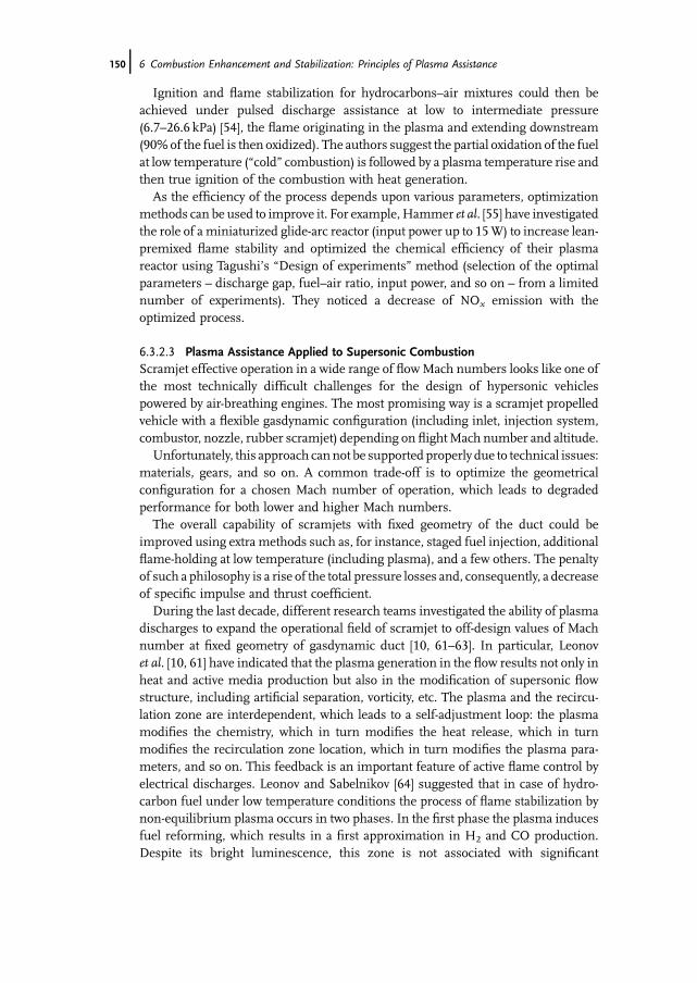
Prospectively, the use of this method might lead to a reduction of total pressurelosses under non-optimal conditions, an enhancement of operation stability, and,consequently, to the extension of the air-breathing corridor of scramjet operability(Figure 6.24).
6.3.3Numerical Simulation
Computational fluid dynamics (CFD) can play an important role in plasma-assistedcombustion. Here, the challenge is the development of coherent physical models of
Figure 6.24 Operating range of air-breathing engines, depending on the flight conditions (altitudeand vehicle velocity), and extension of the scramjet operability by plasma assistance (qualitativescheme). (Adapted from Reference [64].)
6.3 Effect of the Plasma Assistance on Combustion j151
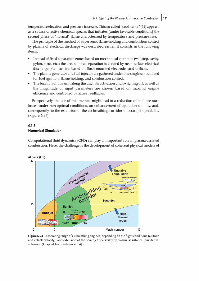
the plasma/flame interaction. This direction develops quickly and different ap-proaches can be found in the literature, such as simulating the effect of the plasmaby calculating theflame and investigating the role of source terms (electrons, species)on the combustion. This approach was investigated by Teixeira [8] to simulate theeffect of filamentary discharges on a tribrachial non-premixed methane–air flame.The cost in CPU time increases with the number of species; therefore, the use ofsimplified kinetics schemes is required. The methane–air combustion kineticsscheme used by Teixeira includes 17 species and 58 reactions (Chemkin format).The effect of the plasma was introduced as a source term of electrons modeling thedischarges occurring between the HV electrode and the flame, and four relatedreactions of electronic dissociation for fuel molecules (coefficients rates of thesereactions from Reference [66]). The source term of electrons was evaluated basedupon current and voltage measurements coupled to a model simulating the electriccircuit. This model was validated by comparison between experimental measure-ments and simulation of the case of a discharge occurring between the HVelectrodetip and anHV probe representing the flame (Figure 6.25). The temporal evolution ofthe deposited electric charge and then of the electron flow rate were obtained byreplacing the values of capacitance and resistivity of the HV probe by those of theflame. Figure 6.25a and b shows the good agreement (both for temporal evolutionand amplitude) between the experimental measurements and the simulation basedon the electrical model.
The electron source term was introduced in the CFD simulation under threesuccessive iterations (�45 ns each) repeated at a 10 kHz frequency. This source term
Figure 6.25 Validation of the electrical model: experimental measurements (a); and simulation (b).
152j 6 Combustion Enhancement and Stabilization: Principles of Plasma Assistance
was spatially distributed to the computationmeshes belonging to a 200-mmdiametermodeling channel, linking the electrode tip location to the flame base. Calculationswere achieved from an initial state of ignited flame both with and without plasmaassistance.
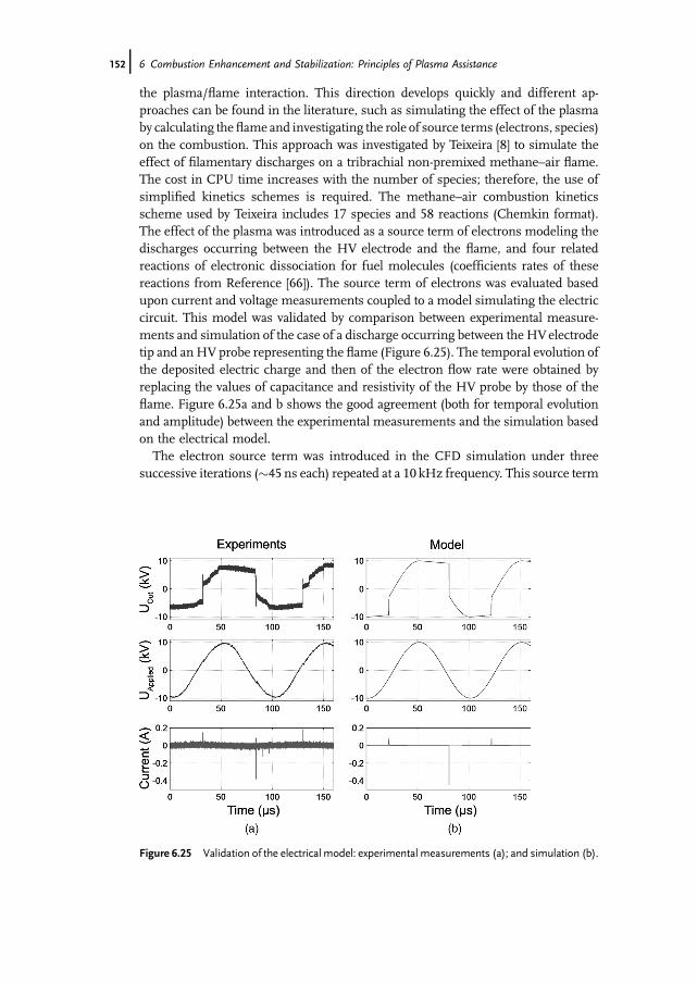
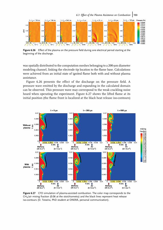
Figure 6.26 presents the effect of the discharge on the pressure field. Apressure wave emitted by the discharge and expanding in the calculated domaincan be observed. This pressure wave may correspond to the weak crackling noiseheard when operating the experiment. Figure 6.27 shows the lifted flame at itsinitial position (the flame front is localized at the black heat release iso-contours)
Figure 6.27 CFD simulation of plasma-assisted combustion. The color map corresponds to theCH4/air mixing fraction (0.06 at the stoichiometry) and the black lines represent heat releaseiso-contours (D. Teixeira, PhD student at ONERA, personal communication).
Figure 6.26 Effect of the plasma on the pressure field during one electrical period starting at thebeginning of the discharge.
6.3 Effect of the Plasma Assistance on Combustion j153
and its time evolution with and without plasma. Noticeably, the unassistedflame is quickly convected out of the calculated field, but not the plasma-assistedflame.
Further calculations will of course usemore complex and reliable kinetics tomodelplasma-chemical processes. Such models, adjusted by experimental measurementsof the ignition delays and the temporal evolution of concentrations of importantradicals for plasma ignition, have been developed. Depending on the simulatedconditions, the vibrationally and electronically excited species are neglected [59, 60] ornot [67, 68]. Such kinetic models remain (for the moment) too big for 2D or 3D CFDbut are interesting for 0D or 1D simulations. The laminar premixed flame velocity inthe case of plasma-assisted combustion could be determined by simulations basedon such kinetics and taking into account the molecular diffusion coefficient of thedifferent species.
6.4Outlook
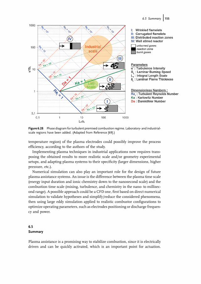
Very promising results have been obtained in plasma-assisted combustion for the lastten years, especially for flame stabilization, flammability extension, and reduction ofthe ignition delay.Nevertheless,most of themare based on small-scaled experiments;industrial applications require investigating the effects of plasma assistance onmorerealistic test rigs, where different flame regimes can occur. Indeed, fundamentalparameters of combustion such as residence time, micro-mixing time, chemicaltime, integral scale of turbulence, and flame thickness (and, respectively, their ratiosexpressed as dimensionless Reynolds number, Damk€ohler number, and Karlowitznumber) do not, in laboratory-scale experiments, always reflect the conditions ofindustrial applications. However, these parameters have a strong influence on theflame structure and its behavior (laminar, wrinkled, corrugated, etc.), as illustrated inthe so-called Borghi diagram (Figure 6.28).
This diagram based on averaged values of different parameters provides onlygeneral trends. Additional elements of understanding the role of dimensionlessnumbers and their link to turbulent premixed flame structure and burning velocitycan be found in the recent review by Driscoll [70].
Moreover, in larger combustors, combustion/acoustic interaction is expected to bemore important, since the level of acoustic pressure is generally much higher.Various methods (passive or active) have been developed to control combustioninstabilities, as described in Chapter 16 by Ducruix et al..
The efficiency of plasma techniques for combustion stabilization in such harshenvironments has yet to be demonstrated. Li et al. [7] have investigated the effectof plasma discharges in a swirl-stabilized gas turbine combustor at moderateflow-rate (5.8 g s�1; w¼ 0.75), paying special attention to the CO and NOx levels inthe exhausts. They found that the transient discharges had a beneficial effect on theoxidation of CO, thanks to the large amount of radicals they generated. The expectedNOx remediation was not observed, but a better positioning (i.e., in a lower
154j 6 Combustion Enhancement and Stabilization: Principles of Plasma Assistance
temperature region) of the plasma electrodes could possibly improve the processefficiency, according to the authors of the study.
Implementing plasma techniques in industrial applications now requires trans-posing the obtained results to more realistic scale and/or geometry experimentalsetups, and adapting plasma systems to their specificity (larger dimensions, higherpressure, etc.).
Numerical simulation can also play an important role for the design of futureplasma assistance systems. An issue is the difference between the plasma time scale(energy input duration and ionic chemistry down to the nanosecond scale) and thecombustion time scale (mixing, turbulence, and chemistry in the nano- to millisec-ond range). A possible approach could be a CFD one, first based on direct numericalsimulation to validate hypotheses and simplify/reduce the considered phenomena,then using large eddy simulation applied to realistic combustor configurations tooptimize operating parameters, such as electrodes positioning or discharge frequen-cy and power.
6.5Summary
Plasma assistance is a promising way to stabilize combustion, since it is electricallydriven and can be quickly activated, which is an important point for actuation.
Figure 6.28 Phase diagram for turbulent premixed combustion regime. Laboratory- and industrial-scale regions have been added. (Adapted from Reference [69].)
6.5 Summary j155
Experiments conducted over the last decades have demonstrated the ability tosuppress pressure oscillations, shorten ignition delays, and extend the flammabilitylimits. These developments have particularly benefited from the progress in diag-nostics tools, especially optical ones. Some of them that are useful for the analysis ofcombustion, plasma, and their interaction are presented here.
Applied to the investigation of plasma effects on non-premixed, premixed, orsupersonic combustion, these techniques have brought some converging elementsof understanding of the plasma assistance effect. In fact, the important effect ofplasma-chemistry (especially through radicals) seems to be proven. However,efficient combustion assistance still requires local heating (by burned gases inrecirculation zones or by the discharge itself) to be initiated. Hot combustion alsoseems to often follow a �cold� combustion induction phase during which oxidationreactions starts; various experiments have demonstrated the strong reduction inignition delay by plasma assistance. Finally, recent studies have focused on thepositioning of plasma area, which is a major aspect of an efficient stabilization of thecombustion.
Acknowledgments
The author would like to acknowledge Dr. Sabelnikov, Dr. Larigaldie, and Dr. Grischfrom ONERA (French Aerospace Laboratory) for valuable discussions due to theirexpertise in combustion processes, plasmas, and optical diagnostics, respectively,and Dr. Brossard for help in preparing the manuscript. The author also wants todedicate this chapter to the memory of Dr. Philippe Magre, who passed away inNovember 2007 at the age of 57.
References
1 Esquiva–Dano, I., Nguyen, H.T., andEscudie, D. (2001) Influence of a bluff-body�s shape on the stabilization regimeof non-premixed flames. Combustion andFlame, 127, 2167–2180.
2 Roth, J.R. (2003) Aerodynamic flowacceleration using paraelectric andperistaltic electrohydrodynamic effects ofa one atmosphere uniformglowdischargeplasma. Physics of Plasmas, 10 (5),2117–2126.
3 Elias, P.-Q., Chanetz, B., Coponet, D.,Benay, R., Larigaldie, S., and Packan, D.(2006) Mach 3 shock-wave unsteadinessalleviation using a negative coronadischarge. 37th AIAA Plasmadynamicsand Lasers Conference, 5–8 June 2006,San Francisco, California.
4 Afanas�ev, V.V. (1999) Active control ofcombustion stability by means of anelectrical discharge. Combustion,Explosion, and Shock Waves, 35 (3),252–260.
5 Candel, S. (2002) Combustion dynamicsand control: progress and challenges.Proceeding of the Combustion Institute,29, 1–28.
6 Docquier, N. and Candel, S. (2002)Combustion control and sensors: a review.Progress in Energy and Combustion Science,28, 107–150.
7 Li, G., Gutmark, E.J., Wang, F., andGundersen, M.A. (2004) Application oftransient non-thermal plasma actuator ina swirl-stabilized gas turbine combustor.40th AIAA-ASME-SAE-ASEE Joint
156j 6 Combustion Enhancement and Stabilization: Principles of Plasma Assistance
Propulsion Conference, 12–14 July 2004,Fort Lauderdale, Florida.
8 Vincent-Randonnier, A. and Teixeira, D.(2008) Plasma assistedmethane diffusionflame: experiments and numericalsimulation. International Journal ofPlasma Environmental Science &Technology, 2 (2), 119–127.
9 Settles, G.S. (2001) Schlieren andShadowgraph Techniques: VisualizingPhenomena in Transparent Media,Springer-Verlag, Berlin.
10 Leonov, S.B., Yarantsev, D.A.,Napartovich, A.P., and Kochetov, I.V.(2006) Plasma-assisted combustion ofgaseous fuel in supersonic duct. IEEETransactions on Plasma Science, 34 (6),2514–2525.
11 Jacobsen, L.S., Carter, C.D., Jackson, T.A.,Schetz, J.A., O�Brien, W.F., Elliott, G.S.,Boguzko, M., and Crafton, J.W. (2002)An experimental investigation of a DCplasma-torch igniter. 11th AIAA-AAAFInternational Conference on Space Planesand Hypersonic Systems and Technology,29 September-4 October 2002, Orleans,France.
12 Kozuka, K., Ozasa, T., Fujikawa, T., andSaito, A. (2003) Schlieren observation ofspark-ignited premixed chargecombustion phenomena using atransparent collimating cylinder engine.Transactions of the ASME, 125, 336–343.
13 Wong, T. and Agarwal, A.K. (2006)Quantitative measurements in anunsteady flame using high-speedrainbow Schlieren deflectometry.Measurements Science and Technology,17, 1503–1510.
14 Alvarez-Herrera, C., Moreno-Hernandez,D., and Barrientos-Garcıa, B. (2007)Temperature measurement of anaxisymmetric flame by using a Schlierensystem. Journal of Optics A: Pure andApplied Optics, 10 (10), 104014–104020.
15 Fomin, N.A. (2008) Diagnostics of rapidlyproceeding processes in fluid and plasmamechanics. Journal of Enginering Physicsand Thermophysics, 81, 68–81.
16 Fomin, N., Lavinskaya, E., and Vitkin, D.(2002) Speckle tomography of turbulentflows with density fluctuations.Experiments in Fluids, 33, 160–169.
17 Nilsen, J. and Johnson, W.R. (2005)Plasma interferometry and how thebound-electron contribution can bendfringes in unexpectedways.AppliedOptics,44 (34), 7295–7301.
18 Fantz, U. (2006) Basics of plasmaspectroscopy. Plasma Source Science andTechnology, 15, 137–147.
19 Laux, C.O., Spence, T.G., Kruger, C.H.,and Zare, R.N. (2003) Optical diagnosticsof atmospheric pressure air plasmas.Plasma Sources Science and Technology, 12,125–138.
20 Gaydon, A.G. (1957) The Spectroscopy ofFlames, JohnWiley & Sons Inc., NewYork.
21 Zizak, G. (2000) Flame emissionspectroscopy: fundamentals andapplications, ICS Training Course onLaser Diagnostics of CombustionProcesses, Cairo, Egypt, http://www.tempe.mi.cnr.it/zizak/tutorial/cairol06-flame-emission.pdf.
22 Vincent-Randonnier, A., Larigaldie, S.,Magre, P., and Sabel�nikov, V. (2007)Experimental study of a methanediffusion flame under dielectric barrierdischarge assistance. IEEE Transactions onPlasma Science, 35 (2), 223–232.
23 Pilla, G., Galley, D., Lacoste, D.A., Lacas,F., Veynante, D., and Laux, C.O. (2006)Stabilization of a turbulent premixedflame using a nanosecond repetitivelypulsed plasma. IEEE Transaction onPlasma Science, 34, 2471–2477.
24 Starikovskaia, S.M., Anikin, N.B.,Pancheshnyi, S.V., and Starikovskii, A.Y.(2002) Time resolved emissionspectroscopy and its applications to studyof pulsed nanosecond high-voltagedischarges. Proceedings of SPIE, 4460,63–73.
25 Kim, W., Do, H., Mungal, M.G., andCappelli, M.A. (2006) Flame stabilizationenhancement and NOx production usingultra short repetitively pulsed plasmadischarges. Proceedings of the 44th AIAAAerospace Sciences Meeting and Exhibit,9–12 January 2006, Reno, NV.
26 Kohse-H€oinghaus, K., Barlow, R.S.,Alden, M., and Wolfrum, J. (2005)Combustion at the focus: laser diagnosticsand control. Proceedings of the CombustionInstitute, 30, 89–123.
References j157
27 Messina,D., Grandin,G.-A., Attal-Tr�etout,B., and Grisch, F. (2008) Laser-basedmeasurements of gas-phase chemistry innon-equilibrium pulsed nanoseconddischarges. 2nd Colloque INCA,October 23–24th 2008, Rouen, France.
28 Ono, R. and Oda, T. (2008) Opticaldiagnostics of pulsed streamer dischargeunder atmospheric pressure. InternationalJournal of Plasma Environmental Science &Technology, 1 (2), 123–129.
29 Cha, M.S., Lee, S.M., Kim, K.T., andChung, S.H. (2005) Soot suppression bynon-thermal plasma in coflow jetdiffusion flame using a dielectric barrierdischarge. Combustion and Flame, 141,438–447.
30 Ganguly, B.N. and Parish, J.W. (2004)Absolute H atom density measurementsin puremethane pulsed discharge.AppliedPhysics Letters, 84 (24), 4953–4955.
31 Funatani, S., Fujisawa, N., and Ikeda, H.(2004) Simultaneous measurement oftemperature and velocity using two-colourLIF combinedwith PIVwith a colourCCDcamera and its application to the turbulentbuoyant plume. Measurement Science andTechnology, 15, 983–990.
32 Messina, D., Attal-Tretout, B., and Grisch,F. (2007) Study of a non-equilibriumpulsed nanosecond discharge atatmospheric pressureusing coherent anti-Stokes Raman scattering.Proceedings of theCombustion Institute, 31, 825–832.
33 van der Mullen, J., Boidin, G., and van deSandea, M. (2004) High-resolutionelectron density and temperature maps ofa microwave plasma torch measured witha 2-D Thomson scattering system.Spectrochimica Acta Part B, 59, 929–940.
34 Kim, Y., Ferreri, V.W., Rosocha, L.A.,Anderson, G.K., Abbate, S., and Kim, K.T.(2006) Effect of plasma chemistry onactivated propane/air flames. IEEETransaction on Plasma Science, 34 (6),2532–2536.
35 Vincent, A., Daou, F., and Amouroux, J.(2002) Characterization of the chemicalbehavior of a DBD wire-cylinder reactorfor NOx removal - determination ofreactional pathways by isotopic labeling.High Temperature Material Processes, 6 (2),167–180.
36 Starikovskaia, S. (2006) Plasma assistedignition and combustion. Journal ofPhysics D: Applied Physics, 39, R265–R299.
37 Fridman, A., Chirokov, A., and Gutsol, A.(2005) Non-thermal atmospheric pressuredischarges. Journal of Physics D: AppliedPhysics, 38, R1–R24.
38 Chang, J.S. (2008) Physics and chemistryof plasma pollution control technology.Plasma Sources Science and Technology,17 (4), 045004–045009.
39 Sch€utze, A., Jeong, J.Y., Babayan, S.E.,Park, J., Selwyn, G.S., and Hicks, R.F.(1998) The atmospheric-pressure plasmajet: a review and comparison to otherplasma sources. IEEE Transactions onPlasma Science, 26 (6), 1685–1694.
40 Ruetsch, G., Vervisch, L., and Linan, A.(1995) Effects of heat release on tripleflames. Physics of Fluids, 7 (9), 1447–1454.
41 Chung, S.H. (2007) Stabilization,propagation and instability of tribrachialtriple flames. Proceeding of the CombustionInstitute, 31, 877–892.
42 Lyons, K.M. (2007) Toward anunderstanding of the stabilizationmechanisms of lifted turbulent jet flames:experiments. Progress in Energy andCombustion Science, 33, 211–231.
43 Boulanger, J., Vervisch, L., Reveillon, J.,and Ghosal, S. (2003) Effects of heatrelease in laminar flames lifted on roundjets. Combustion and Flame, 134, 355–368.
44 Vincent-Randonnier, A., Larigaldie, S.,Magre, P., and Sabel�nikov, V. (2007)Plasma assisted combustion: effect of acoaxial DBD on a methane diffusionflame. Plasma Sources Science andTechnology, 16, 149–160.
45 Criner, K., Cessou, A., and Vervisch, P.(2007) A comparative study of thestabilization of propane lifted jet-flames bypulsed, AC and DC high-voltagedischarges. Proceedings of the EuropeanCombustion Meeting 3, 2007.
46 Lee, S.M., Cheol, S.P., Cha, M.S., andChung, S.H. (2005) Effect of electric fieldson the lift-off of non-premixed turbulentjet flames. IEEE Transactions on PlasmaScience, 33, 1703–1709.
47 Kim, W., Do, H., Mungal, M.G., andCappelli, M.A. (2006) Plasma-dischargestabilization of jet diffusion flames. IEEE
158j 6 Combustion Enhancement and Stabilization: Principles of Plasma Assistance
Transactions on Plasma Science, 34 (6),2545–2551.
48 Kim, W., Do, H., Mungal, M.G., andCappelli, M.A. (2008) Optimal dischargeplacement in plasma-assisted combustionof a methane jet in cross flow. Combustionand Flame, 153, 603–615.
49 Rosocha, L.A., Kim, Y., Anderson, G.K.,and Abbate, S. (2007) Combustionenhancement using silent electricaldischarges. International Journal of PlasmaEnvironmental Science & Technology, 1 (1),8–13.
50 Marcum, S.D. and Ganguly, B.N. (2005)Electric-field-induced flame speedmodification. Combustion and Flame,143 (1), 23–36.
51 Zaidi, S.H., Stockman, E., Qin, X.,Zhao, Z., Macheret, S., Ju, Y., Miles, R.B.,Sullivan, D.J., and Kline, J.F. (2006)Measurements of hydrocarbon flamespeed enhancement inHigh-Qmicrowavecavity. AIAA Aerospace Sciences Meetingand Exhibit, 9–12 January 2006, Reno,Nevada.
52 Bellenoue, M., Labula, S.A., and Engles,M. (2005) Corona discharge ignition andcombustion promotion of methane/airmixtures. Proceedings of the EuropeanCombustion Meeting, 2005.
53 Starikovskii, A.Yu. (2005) Plasmasupported combustion. Proceedings of theCombustion Institute, 30, 2405–2417.
54 Lou, G., Bao, A., Nishihara,M., Keshav, S.,Utkin, Y.G., and Adamovich, I. (2006)Ignition of premixed hydrocarbon-airflows by repetitively pulsed, nanosecondpulse duration plasma. AIAA AerospaceSciences Meeting and Exhibit, 9–12January 2006, Reno, Nevada.
55 Hammer, T., Most, D., Schlemm, P.,Beyrau, F., and Leipertz, A. (2008) Glide-arc stabilization of lean methane-aircombustion. Proceedings of theInternational Symposium on Non-Thermal Plasma Technology 6, 2008.
56 Chintala, N., Bao, A., Lou, G., andAdamovich, I. (2006) Measurements ofcombustion efficiency in nonequilibriumRF plasma-ignited flows. Combustion andFlame, 144, 744–756.
57 Vinogradov, V.A., Shikhman, Y.M.,Gritsinin, S.I., Davidov, A.M.,
Knyazev, V.Y., and Kossiy, I. (2007)Application of MW plasma generator forignition of kerosene/air mixture. AIAAAerospace Sciences Meeting and Exhibit,8–11 January 2007, Reno, Nevada.
58 Starikovskaia, S.M., Kukaev, E.N., Kuksin,A.Yu., Nudnova, M.M., and Starikovskii,A.Yu. (2004) Analysis of the spatialuniformity of the combustion of a gaseousmixture initiated by a nanoseconddischarge. Combustion and Flame,139, 177–187.
59 Kosarev, I.N., Aleksandrov, N.L.,Kindysheva, S.V., Starikovskaia, S.M., andStarikovskii, A.Yu. (2008) Kinetics ofignition of saturated hydrocarbons bynonequilibrium plasma: CH4-containingmixtures. Combustion and Flame, 154,569–586.
60 Kosarev, I.N., Aleksandrov, N.L.,Kindysheva, S.V., Starikovskaia, S.M., andStarikovskii, A.Yu. (2009) Kinetics ofignition of saturated hydrocarbons bynonequilibrium plasma: C2H6- toC5H12-containing mixtures. Combustionand Flame, 156, 221–233.
61 Leonov, S.B. and Yarantsev, D.A. (2007)Plasma-induced ignition and plasma-assisted combustion in high-speed flow.Plasma Sources Science and Technology,16, 132–138.
62 Esakov, I.I., Grachev, L.P., Khodataev, K.V.,Vinogradov, V.A., and Van Wie, D.M.(2006) Propane–air mixture combustionassisted by MW discharge in a speedyairflow. IEEE Transaction on PlasmaScience, 34 (6), 2497–2506.
63 Do, H., Mungal, M.G., and Cappelli, M.A.(2008) Jet flame ignition in a supersoniccrossflow using a pulsed nonequilibriumplasma discharge. IEEE Transaction onPlasma Science, 36 (6), 2918–2923.
64 Leonov, S. and Sabelnikov, V. (2008)Electrically driven supersonic combustor.Proceedings of the 6th EuropeanSymposium on Aerothermodynamics forspace vehicles, 3–6 November 2008,Versailles, France.
65 Kim, W., Mungal, M.G., and Cappelli,M.A. (2008) Formation and role of coolflames in plasma-assisted premixedcombustion. Applied Physics Letters,92 (5), 051503.
References j159
66 Masi, M., Cavallotti, C., and Carr�a, S.(1998) Different approaches for methaneplasma modeling. Chemical EngineeringScience, 53 (22), 3875–3886.
67 Naumov, V.V., Chernukho, A.P.,Starik, A.M., and Titova, N.S. (2003)Modeling of plasma-chemicalinitiation of detonation in a supersonicflow of combustible mixturescombustion and atmospheric pollution,Combustion and Atmospheric Pollution(eds G.D. Roy, S.M. Frolov, and A.M.Starik), Torus Press, Moscow,pp. 312–317.
68 Starik, A.M. and Titova, N.S. (2004)Possibility of initiation of combustion ofCH4-O2 (air) mixtures with laser-inducedexcitation of O2 molecules. Combustion,
Explosion, and Shock Waves, 40 (5),499–510.
69 Borghi, R. (1988) Turbulent combustionmodeling. Progress in Energy andCombustion Science, 14 (4), 245–292.
70 Driscoll, J.F. (2008) Turbulent premixedcombustion: flamelet structure and itseffect on turbulent burning velocities.Progress in Energy and Combustion Science,34 (1), 91–134.
71 Vincent–Randonnier, A. and Teixeira, D.(2009) Combustion Enhancement andstabilization by Plasma Discharges:Investigation on the Plasma/FlameInteraction. Proceedings of the InternationalSymposium on Applied Plasma Science, 7,47–50.
160j 6 Combustion Enhancement and Stabilization: Principles of Plasma Assistance


