
General-Purpose AC Servo
MODEL
MRZJW3- SETUP81EINSTALLATION GUIDE
Servo Configuration Software
Thank you for choosing the Mitsubishi general-purpose AC servo MELSERVO Servo Configuration Software.To optimize the use of the Servo Configuration Software, please read over this Installation Guide and the corresponding AC servo Installation Guide before using the software. After reading the Installation Guide, always place this Installation Guide in a safe place.
G

A - 1
Safety Instructions (Always read these instructions before using the equipment.)
Do not attempt to install, operate, maintain or inspect the servo amplifier and servo motor until you have readthrough this Installation Guide, and appended documents carefully and can use the equipment correctly. Donot use the servo amplifier and servo motor until you have a full knowledge of the equipment, safetyinformation and instructions.In this Installation Guide, the safety instruction levels are classified into "WARNING" and "CAUTION".
WARNING Indicates that incorrect handling may cause hazardous conditions,resulting in death or severe injury.
CAUTION Indicates that incorrect handling may cause hazardous conditions,resulting in medium or slight injury to personnel or may cause physicaldamage.
Note that the CAUTION level may lead to a serious consequence according to conditions. Please follow theinstructions of both levels because they are important to personnel safety.What must not be done and what must be done are indicated by the following diagrammatic symbols:
: Indicates what must not be done. For example, "No Fire" is indicated by .
: Indicates what must be done. For example, grounding is indicated by .
In this Installation Guide, instructions at a lower level than the above, instructions for other functions, and so onare classified into "POINT".After reading this Installation Guide, always keep it accessible to the operator.
CAUTIONBefore executing the test mode, always read Section 2.3 "Precaution for testmode".
Windows is a trademark of Microsoft Corporation.The "Mitsubishi general-purpose AC servo MELSERVO Servo Configuration Software" is a production ofMitsubishi Electric Corporation. Mitsubishi Electric Corporation reserves the copyright and all other rights ofthis software.This Installation Guide may not be reproduced or copied, in whole or part, without written consent ofMitsubishi Electric Corporation.All other company and product names contained in this Installation Guide are registered trademarks ortrademarks of their respective companies.

A - 2
MEMO

1
CONTENTS
1. INTRODUCTION 1-1 to 1-14
1.1 Specifications ........................................................................................................................................ 1-1 1.2 System configuration ........................................................................................................................... 1-3
1.2.1 Components .............................................................................................................................. 1-3 1.2.2 Communication cable .............................................................................................................. 1-4 1.2.3 Configuration diagrams .......................................................................................................... 1-6
1.3 Basic terms ............................................................................................................................................ 1-7 1.4 Basic operations .................................................................................................................................... 1-8 1.5 Screen definitions ............................................................................................................................... 1-10 1.6 Installation procedure ........................................................................................................................ 1-11
2. HOW TO USE THE SOFTWARE 2-1 to 2-8
2.1 Operation ............................................................................................................................................... 2-1 2.1.1 Start-up ..................................................................................................................................... 2-1 2.1.2 Command selection procedures .............................................................................................. 2-1 2.1.3 Operation procedures within the window ............................................................................. 2-2
2.2 Commands and display windows ........................................................................................................ 2-3 2.3 Precautions for test mode .................................................................................................................... 2-5 2.4 Simple language for program operation ............................................................................................. 2-6
2.4.1 Language .................................................................................................................................. 2-6 2.4.2 Program example ..................................................................................................................... 2-7 2.4.3 Instruction ................................................................................................................................ 2-7
3. TROUBLESHOOTING 3-1 to 3-2
3.1 Communication error ........................................................................................................................... 3-1 3.2 Message at startup ............................................................................................................................... 3-1 3.3 Message at program shutdown ........................................................................................................... 3-2 3.4 HELP display ........................................................................................................................................ 3-2

2
MEMO

1 - 1
1. INTRODUCTION
1. INTRODUCTION
1.1 Specifications
Using the communication function of the servo amplifier, the Servo Configuration Software allowsfunctions, such as parameter setting change, point data maintenance, graph, program operation modeand test mode, to be implemented from a personal computer.
Servo amplifierItem
MR-H-A MR-H-B MR-H-AC MR-C MR-J2-A MR-J2-B MR-J2-C MR-H-TN
Communication signal Compliant with RS-232C9600bps
Baudrate19200bpsStation Selection
SystemAutomatic DemoAmplifier Data, HighSpeed MonitorMonitorTrend GraphDisplayHistoryAmplifier DataAlarmsGraph display beforealarmI/O DisplayFunction Device DisplayNo Motor RotationSettle timeTotal Power-on TimeAmplifier Version InfoMotor InformationTuning dataAbsolute Encoder Data
Diagnostics
Automatic VoltageControlParameter List
ParametersI/O DevicesJogPositioningOperation w/o MotorForced outputDemo Mode
Test
Single-step feedPosition blockSpeed blockTeach
Position-Data
Point Table

1 - 2
1. INTRODUCTION
Specification Item MR-J2-03A5 MR-J2-03B5 MR-J2-03C5 MR-J2A-XA MR-J2-C-S100Communication signal Compliant with RS-232C
9600bpsBaudrate
19200bpsStation Selection
SystemAutomatic Demo
MonitorAmplifier Data, HighSpeed Monitor, TrendGraphDisplayHistoryAmplifier DataAlarmsGraph display beforealarmDigital I/O DisplayFunction DevicesNo Motor RotationSettle timeTotal Power-on TimeAmplifier Version InfoMotor InformationTuning dataAbsolute Encoder Data
Diagnostics
Automatic VoltageControlData setList DisplayChange list displayDetails Display
Parameters
I/O DevicesJogPositioningOperation w/o MotorForced outputDemo ModeSingle-step feed
Test
Program TestPosition/Speed blockTeachPositionPoint TablesProgram DataProgram-
Data Indirect Addressing
Trend Graph in the monitor function and Graph display before alarm in the alarm function may be usedby the servo amplifiers having the following software versions. If Trend Graph or Graph display beforealarm is used by the other servo amplifier, a communication error will occur but the other functions maybe used.
Servo Amplifier Servo Amplifier Software Version
MR-H-A BCD-B12W002-D0 or laterMR-H-B BCD-B13W000-B0 or later
MR-H-AC BCD-B15W000-B0 or laterMR-C BCD-B18W000-A1 or later
MR-J2-C-S100 BCD-B20W304-A2 or later

1 - 3
1. INTRODUCTION
1.2 System configuration
1.2.1 Components
To use the Servo Configuration Software, the following components are required in addition to the servo amplifier and servo motor. Configure the system according to the Installation Guide of each equipment:
Equipment (Note 1) Description
(Note 2, 3, 4, 5, 6, 7) Personal computer
(IBM PC/AT compatible)
OS
Microsoft® Windows® 8.1 Enterprise Operating System Microsoft® Windows® 8.1 Pro Operating System Microsoft® Windows® 8.1 Operating System Microsoft® Windows® 8 Enterprise Operating System Microsoft® Windows® 8 Pro Operating System Microsoft® Windows® 8 Operating System Microsoft® Windows® 7 Enterprise Operating System Microsoft® Windows® 7 Ultimate Operating System Microsoft® Windows® 7 Professional Operating System Microsoft® Windows® 7 Home Premium Operating System Microsoft® Windows® 7 Starter Operating System Microsoft® Windows Vista® Enterprise Operating System Microsoft® Windows Vista® Ultimate Operating System Microsoft® Windows Vista® Business Operating System Microsoft® Windows Vista® Home Premium Operating System Microsoft® Windows Vista® Home Basic Operating System Microsoft® Windows® XP Professional Operating System Microsoft® Windows® XP Home Edition Operating System Microsoft® Windows® 2000 Professional Operating System Microsoft® Windows NT® Workstation Operating System Version 4.0 Microsoft® Windows® Millennium Edition Operating System Microsoft® Windows® 98 Second Edition Operating System Microsoft® Windows® 98 Operating System Microsoft® Windows® 95 Operating System
CPU
Pentium133MHz or more(Windows® 95, Windows® 98, Windows NT® Workstation 4.0, Windows® 2000) Pentium150MHz or more(Windows® Me) Pentium300MHz or more(Windows® XP) 32-bit (x86) processor of 1GHz or more(Windows Vista®) 32-bit (x86) or 64-bit (x64) processor of 1GHz or more(Windows® 7, Windows® 8, Windows® 8.1)
Memory
16MB or more(Windows® 95),24MB or more(Windows® 98) 32MB or more(Windows® Me,Windows NT® Workstation 4.0,Windows® 2000) 128MB or more(Windows® XP) 1GB or more(Windows Vista®, Windows® 7, Windows® 8, Windows® 8.1)
Hard Disk 30MB or more of free space Communication
interfaces Serial port
Display One whose resolution is 800 600 or more and that can provide a high color (16 bit) display. Connectable with the above personal computer.
Keyboard Connectable with the above personal computer. Mouse Connectable with the above personal computer. Note that a serial mouse is not used. Printer Connectable with the above personal computer.
Communication cable MR-HPCATCBL3M, MR-CPCATCBL3M, MR-JRPCATCBL3M When this cannot be used, refer to Section 1.2.2 and fabricate
RS-232C option unit MR-C-T01 Required when using the Servo Configuration Software with the MR-C servo amplifier.
Note 1. Windows and Windows NT are the registered trademarks of Microsoft Corporation in the United State and other countries. Pentium is the registered trademarks of Intel Corporation.
2. On some personal computers, this software may not run properly. 3. 64-bit Windows® XP, 64-bit Windows Vista® are not supported. 4. If Microsoft® Windows ® XP or later is used, the following functions cannot be used. If any of the following functions is used, this product may not operate
normally. Start of application in Windows® compatible mode Fast user switching Remote desktop Big fonts (Detail settings of screen property) DPI setting other than the normal size (96DPI) (Detail settings of screen property)
5. If Windows Vista® or later is used, log in as a user having Administrator privileges. 6. If Windows® 7 or later is used, the following functions cannot be used.
Windows XP Mode Touch
7. If Windows® 8 or later is used, the following functions cannot be used. Hyper-V Modern UI Style

1 - 4
1. INTRODUCTION
1.2.2 Communication cable
(1) SelectionUse a communication cable for connection of the personal computer and the servo amplifier.Choose the communication cable according to the shape of the RS-232C connector of the personalcomputer used.
POINTDepending on the personal computer used, any of the following cables maybe used.Confirm the RS-232C connector signal carefully, refer to this section andfabricate the cable.
TypeLength
[m(feet)]
Servoamplifier or
Interface unitApplication Description
Connector: DE-9PF-NCase: DE-C1-J6-S6(Japan Aviation Electronics)
Connector: DE-9SF-NCase: DE-C1-J6-S6(Japan Aviation Electronics)MR-HPCATCBL3M 3
(9.84)
MR-H-A(N)MR-H-B(N)
MR-H-AC(N)MR-H-TN
For IBM series(D-SUB 9 pins)
Connector: 10120-6000ELShell kit: 10320-3210-000(3M or equivalent)
Connector: DE-9SF-NCase: DB-C1-J6-S6(Japan Aviation Electronics)MR-CPCATCBL3M 3
(9.84)
MR-CMR-J2-AMR-J2-BMR-J2-C
MR-J2-C-S100MR-J2-A-XA
For IBM series(D-SUB 9 pins)
Connector: 5557-04R-210Terminal: 5556(molex)
Connector: DE-9SF-NCase: DE-C1-J6-S6(Japan Aviation Electronics)MR-JRPCATCBL3M 3
(9.84)
MR-J2-03A5MR-J2-03B5MR-J2-03C5
For IBM series(D-SUB 9 pins)
For fabrication, refer to the connection diagram in this section. When fabricating the cable, read andfollow the instructions below:1) Always use a multi-core cable with a shield and connect the shield to FG securely.2) Wiring distance depends on surrounding environment but should be as short as possible.
Maximum distance is 15m(49.2feet) in environmentally good places with little noise, e.g. offices.

1 - 5
1. INTRODUCTION
(2) Communication connector signal pin-outsa) MR-H-A(N)/B(N)/AC(N)/TN
Servo amplifier side connector (CN4)b) MR-C: RS-232C option side connector (CN3A)
MR-J2-A/B/C: Servo amplifier side connectorMR-J2-A-XA(CN3)MR-J2-C-S100
16
27
38
49
5(Note)
P5
FG
RXD
TXD
GND
Note: Pin 9 is designed for use with a parameter unit powersupply and cannot be used for other purposes.
12
3
5
4
6
7
9
8
10
1112
1314
1516
1718
1920
RXDGND
TXDGND
P5E
c) MR-J2-03A5/03B5/03C5Servo amplifier side connector (CNP3)
3 1
4 2
SD LG
TXD RXD
(3) Cable connection diagrams
MR-HPCATCBL3MPersonal computer side
Servo amplifierside
35
21 FG
RXD
TXDLG
3
257
4
86
TXD
RXDGNDRTS
DTR
CTSDSR
D-SUB9 pins D-SUB9 pins
3
257864
2
1211
1 TXD
RXDGNDRTSCTSDSRDTR
FGRXD
TXDLG
LG
D-SUB9 pins Half-pitch 20 pins
MR-CPCATCBL3MPersonal computerside
Servo amplifierside or Interface unit
Plate
2
3
7
4
5
2
41
386
RXD
TXDLG
SD
TXD
RXDGNDRTSCTSDSRDTR
D-SUB9 pins
Servo amplifier side
MR-JRPCATCBL3MPersonal computerside

1 - 6
1. INTRODUCTION
1.2.3 Configuration diagrams
(1) MR-H-A(N)/B(N)/AC(N)/TN
CN4 CN2
Personal computer
Communication cable
Servo amplifier
To RS-232C connector
Servo motor
(2) MR-C
RS-232Coption unitMR-C-T01
CN3 CN2
TO RS-232C connector
Servo amplifier
Servo motor
Communicationcable
CN3
CN3A
Personal computer
(3) MR-J2-A/B/C
CN3 CN2
Personal computer
Communication cable
Servo amplifier
To RS-232C connector
Servo motor
(4) MR-J2-03A5/03B5/03C5
CNP3 CN2
Personal computer
To RS-232Cconnector
Communication cable
Servo amplifier
Servo motor

1 - 7
1. INTRODUCTION
1.3 Basic terms
1) Mouse pointerAn on-screen arrow which moves with movements of the mouse.
2) PointTo move the mouse pointer to a particular item or position on the screen.
3) ClickTo press and release the left button of the mouse once.
4) Double-clickTo press and release the left button of the mouse twice.
5) DragTo hold down the left button of the mouse and move the mouse.
6) FocusHighlights characters, button or the like when the menu or button is ready to accept an input from thekeyboard.
7) Text boxBox used to enter characters.
8) List boxBox used to select one of several items.
9) Combo boxBox used to select one of several items.
10) Check boxBox used to select one or more of several items. When a choice is made a mark appears in the box.
11) Option buttonButton used to select only one of several items. When a choice is changed moves to a new choice.

1 - 8
1. INTRODUCTION
1.4 Basic operations
(1) Closing the windowClick the closing bottom at top right corner of the window.
Click
(2) Moving the focus from one window to anotherClick the button of the task bar corresponding to the window to be used.
Click
(3) Moving the windowPoint to the title bar, drag the window to the required position, and release the button.
Drag

1 - 9
1. INTRODUCTION
(4) Moving the focus to the menu bar
Click the menu bar. To move the focus to a window, click the window.
Click
Click
(5) Moving the focus inside the window Click the object to be operated (such as a text box). When the object to be operated is a button, clicking it will start its processing.
Click
Click
<Short-cut keys> Any of the following short-cut keys may be used to perform operation from the keyboard:
Intended operation Keyboard
End program “Alt” “F4”
Show start menu “Ctrl” “Esc”
Change window “Alt” “Tab”
Change object “Tab”

1 - 10
1. INTRODUCTION
1.5 Screen definitions
2) 5) 4)
1)3)
1) Title bar2) Menu title3) Menu bar
Shows the menu title.4) MenuCommand menu in tier 15) System setting display area
Shows the servo amplifier and baudrate which have been set.

1 - 11
1. INTRODUCTION
1.6 Installation procedure
In this procedure, it is assumed that the hard disk drive of the personal computer is C and the CD drive is D. Before running this program, always close all Windows programs. 1) Insert CD-ROM in Drive D (CD drive). Then, click the “Start” button of the task bar to open the start
menu, specify the file name, and click “Run”. When the following window has appeared, type "D:\SETUP81E\DISK1\SETUP.EXE" and click the “OK” button.
2) After the above window, the following window appears. Click “Next>” button.

1 - 12
1. INTRODUCTION
3) The User Information screen appears. Type your full name and company name and click “Next>” button.
4) The Choose Destination Location screen appears. When you specify the destination folder and click
“Next>” button, installation starts.

1 - 13
1. INTRODUCTION
5) When installation ends, any of the following screens appears. Click the “Finish” button to exit from
Setup.
POINT
In the corresponding window, to stop installation, click the “Cancel” button or press the “Escape”.

1 - 14
1. INTRODUCTION
MEMO

2 - 1
2. HOW TO USE THE SOFTWARE
2. HOW TO USE THE SOFTWARE
2.1 Operation
The method of selecting the command is the operation procedures using the mouse. Unavailable commands are grayed out. 2.1.1 Start-up
1. Windows® 7 or earlier 1) Click the “Start” button of the task bar to open the menu. 2) Point to submenu “MELSERVO”, “SETUP_Software” from “Programs”. Then, Click “SETUP81E”.
2. Windows® 8 1) Using the mouse, right click on the start screen to display the Apps Views from “All apps”. 2) Click on “SETUP81E” from the “MELSERVO” group.
3. Windows® 8.1
1) From the arrow button located on the lower left of the start screen, the Apps View is displayed. 2) Click on “SETUP81E” from the “MELSERVO” group.
2.1.2 Command selection procedures
1. Clicking method 1) Click the menu title on the menu bar to open the menu. 2) Point to and click the command to be selected.
2. Dragging method
Point to the menu title on the menu bar, hold down the left button and drag the mouse to the command to be selected, and release the button.

2 - 2
2. HOW TO USE THE SOFTWARE
2.1.3 Operation procedures within the window
Within the operation window, enter data and/or press the button.
(1) Pressing a buttonClick the button in the window.
(2) Entering dataClick the setting area to move the focus there, and enter data from the keyboard.
(3) Selecting dataClick the data to be selected.
81E
(4) Selecting the combo box data, etc.1) Click on the right of the setting portion to open the combo box.2) Make selection by clicking the data or like to be chosen.
(5) Pressing the option buttonClick the item or button.

2 - 3
2. HOW TO USE THE SOFTWARE
2.2 Commands and display windows
The following diagram shows a sequence of commands and windows.
Menu
Exit
Open
Initial screen
File selection
System settings
Save
System settings
Station Selection
Automatic Demo
Version Information
Station settings
Automatic Demo
Version information
Amplifier Data
High Speed Monitor
Trend Graph
Moniter
System
File
Alarms Display
History
Amplifier Data
Amplifier Data Display
High Speed Monitor
Graph
Alarm Display
Alarm History
Amplifier Data
Demo OperationMode
Program Operation-Edit
Monitor detailed information
Amplifier MonitorParameter Selection
Graph selection
Axis Selection
Scale change
Alarm-reset
Alarm-history-clear
Graph display beforealarm
Axis Selection Scale change
Command Display window
To next page
Trigger selection

2 - 4
2. HOW TO USE THE SOFTWARE
Menu
Digital I/O display
Details of FunctionDevices
Command Display window
Continued from preceding page
I/O Batch DisplayI/O DisplayDiagnostics
Display all functiondevices
Motor output disabled
Settle time display
Accumulated power-ontime display
Amplifier FirmwareVersion
Motor Data Display
Tuning data display
Absolute EncorderData
Automatic VoltageControl offset
Parameter list
Input/Output Devices
Parameter change list
Parameter detailedinformation
Feed system selection
Display Free Pins
Function Devices
No Motor Rotation
Settle Time
Total Power-on Time
Amplifier VersionInfo
Motor Data Display
Tuning Data
Absolute EncoderData
Automatic VoltageControl
Parameter List
I/O Devices
Parameters
Jog mode
Positioning mode
Operation WithoutMotor Selection
Forced output mode
Demo Operation Mode Program Operation-Edit
Single-step mode
Position block list
Speed block list
Teach
Point Table List
Help
JogTest
Positioning
Operation w/o Motor
Forced Output
Demo Mode
Single-step Feed
Position BlockPoint-data
Speed Block
Teach
Point Tables
Help

2 - 5
2. HOW TO USE THE SOFTWARE
2.3 Precautions for test mode
WARNING
Always touch the switches with dry hands. You may get an electric shock if youtouch them with wet hands.Always operate the equipment with the front cover installed. Removing the frontcover will expose the terminals and charged area having high voltages, which maylead to an electric shock.Keep the front cover closed while power is on the equipment is running.Otherwise, you may get an electric shock.
CAUTION
Before starting operation, make sure that the parameters are set to correct values.Depending on machines, they may operate unpredictably.While power is on or for some time after power-off, keep clear of the servoamplifier´s heat sink and regenerative brake resistor, the servo motor, etc. as theymay be high temperatures. Otherwise, you may get burned.
(1) Servo onIn the Jog, Positioning, Demo Mode or Single-step Feed available in the Test, the servo amplifier'sdigital input signal SON is automatically switched on in the servo amplifier to start operation,independently of the ON/OFF status of SON. Also, any external command pulse or input signal(except emergency stop) is not accepted until the test mode window is closed to terminate thecommand.SON is automatically switched on by the following operation:
Test mode Mouse
Jog Click the “Forward” or “Reverse” button.The servo motor rotates while you are clicking the button.
Positioning Click the “Forward” or “Reverse” button.Demo Mode Click the “Start” button.
(2) Stop
POINTTo make an emergency stop, switch off the emergency stop signal of theservo amplifier or shut off the input power.
1) Perform the following operation to stop the test mode:Test mode Mouse
Jog Click the “Pause” button.Positioning Click the “Pause” button.Demo Mode Click the “Reset” button.
2) The servo motor will stop if either of the following situations occurs in the test mode:The communication cable is disconnected.If the window is dragged or the other menu is opened, communication between the personalcomputer and the servo amplifier may be suspended temporarily, stopping the servo motortemporarily.

2 - 6
2. HOW TO USE THE SOFTWARE
2.4 Simple language for program operation
The language used in the program operation-edit window will be described below.
2.4.1 Language
The chart below describes the commands in the program operation-edit window to execute the programoperation mode, in which the MR-H-A(N) or MR-J2-A and MR-J2-03A5 goes into the position controlmode.Describe a program in upper case characters and Enter or Return at the end of a line. Up to 300 lines maybe described.
Command Name Setting(**: Set value)
Setting range Unit Description
SPN Feedrate SPN (**)0 to permissibleinstantaneousspeed
r/min
Used to set the command speed given to the servomotor for positioning. The set value should be notmore than the permissible speed of the servo motorused.
STC Acceleration/decel-eration time STC (**) 0 to 50000 ms
Used to set the acceleration/deceleration time. (Timerequired to reach the rated speed of the correspondingservo motor)
MOV Move command MOV (**)9999999
to9999999
pulse
Used to execute movement by the preset pulses.Positioning operation is performed with the set valuesof the feedrate (SPN) and acceleration /decelerationtime (STC).No symbol: CCW rotation, : CW rotationUsed to hold the next operation until the preset digitalinput signal (DI) of the servo amplifier switches on. Bysetting 99, the next operation will be performedunconditionally. Set the input signal as listed below:For the MR-J2-A, any signal not allocated by signalassignment in the position control mode usingparameters No. 43 to 48 will be invalid if it is selected.This command is unavailable for the MR-H-B and MR-J2-B.
SetValue
MR-H-A(N)
MR-H-AC(N)
MR-J2-A
MR-H-TN
MR-J2-03A5
0 SON SON SON SON SON1 TL DEC LSP DEC LSP2 PC JFS LSN JFS LSN3 RES STP TL STP TL4 LSP LSP LSP5 LSN LSN PC LSN PC6 CR CR RES CR RES7 DI0 DI0 CR DI0 CR8 DI1 DI1 DI19 DI2 DI2 DI210 DI3 ST1 ST111 DI4 ST2 ST299 Unconditional
SYNC Waiting externalsignal to switch on SYNC (**) As listed in the
table at right.
TIM Dwell commandtime TIM (**) 1 to 50 s Used to hold the next operation until the preset time
elapses.
TIMES Program countcommand TIMES (**) 1 to 99 Times
Used to specify the number of cycles or times (fromTIMES to STOP) that the positioning is to be repeated.Enter the TIMES (**) at the beginning and STOP atthe end of a cycle. Not required for one positioningcycle.
STOP Program stop Used to stop the program being executed.Need not be described on the last line.

2 - 7
2. HOW TO USE THE SOFTWARE
2.4.2 Program example
As soon as the “Start” button is clicked, SON is switched on automatically to start operation. Timing chart
Motor speed : 2000r/minAcceleration/ : 1200msdecelerationtimeMovement : 10000 pulse
Operation 2
Motor speed : 1000r/minAcceleration/ : 1200msdecelerationtimeMovement : 12000 pulse
Operation 1
Performed three times.
Servo motorspeed
ONOFF
CCW
CW
SON
10s
Program TIMES (3) ................................ Repeats the program up to STOP three times. SYNC (0) ................................. Holds the program from running until the input signal with the set value of 0 (SON) switches on. SPN (1000) ............................. Sets the command speed to 1000r/min. STC (1200) .............................. Sets the acceleration/deceleration time to 1200ms. MOV (12000) .......................... Executes movement by 12000 pulses in the CCW direction. TIM (10) .................................. Hold the next operation for 10s. SPN (2000) ............................. Sets the command speed to 2000r/min. MOV ( 100000) ..................... Executes movement by 100000 pulses in the CW direction. STOP In this example, the acceleration/deceleration time in Operations 1 and 2 are the same. In this case, the acceleration/deceleration time in Operation 2 need not be set. In this way, set values different from those in the preceding operation need only be described in the operation program. 2.4.3 Instruction
When the program operation mode is executed with the program operation mode window and another window (Amplifier Data Display window) being displayed at the same time, the program may progress slower, making the dwell command time longer than the set value.
Operation 1
Operation 2

2 - 8
2. HOW TO USE THE SOFTWARE
MEMO
3 - 1
3. TROUBLESHOOTING
3. TROUBLESHOOTING
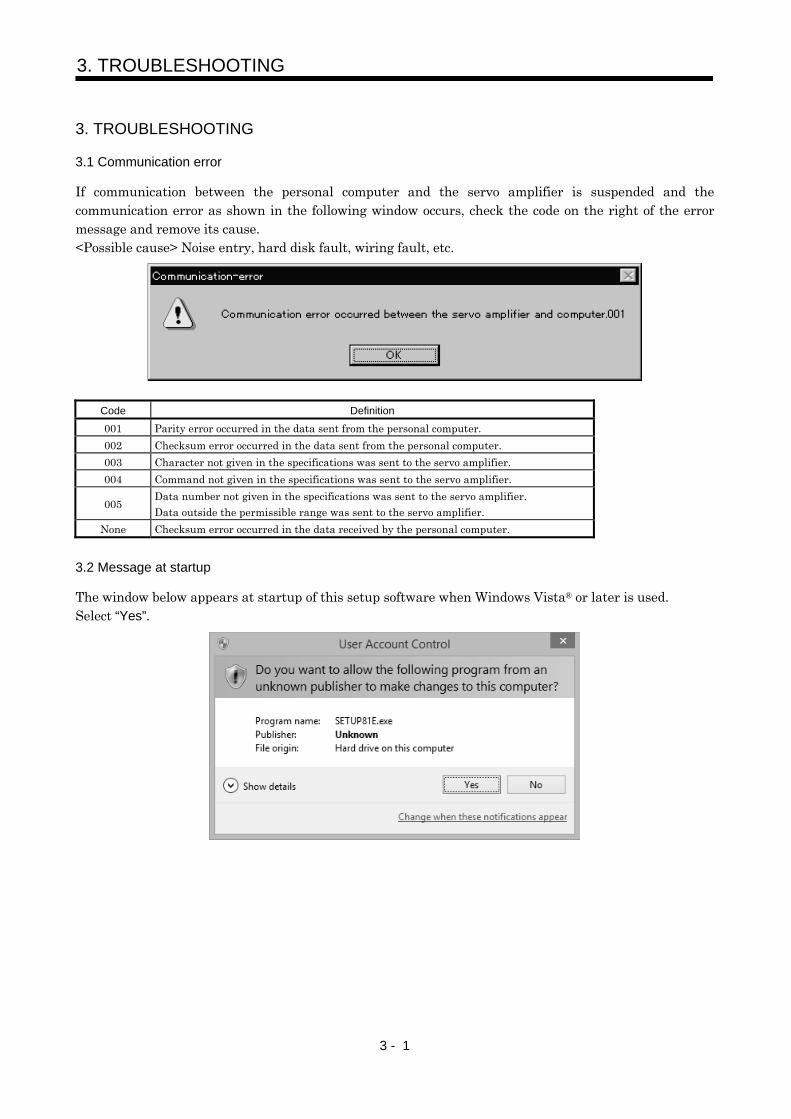
3.1 Communication error
If communication between the personal computer and the servo amplifier is suspended and the communication error as shown in the following window occurs, check the code on the right of the error message and remove its cause. <Possible cause> Noise entry, hard disk fault, wiring fault, etc.
Code Definition
001 Parity error occurred in the data sent from the personal computer.
002 Checksum error occurred in the data sent from the personal computer.
003 Character not given in the specifications was sent to the servo amplifier.
004 Command not given in the specifications was sent to the servo amplifier.
005 Data number not given in the specifications was sent to the servo amplifier.
Data outside the permissible range was sent to the servo amplifier.
None Checksum error occurred in the data received by the personal computer.
3.2 Message at startup
The window below appears at startup of this setup software when Windows Vista® or later is used. Select “Yes”.

3 - 2
3. TROUBLESHOOTING
3.3 Message at program shutdown
The window below appears at program shutdown when Windows Vista® or later is used. Select “This program is installed correctly”.
3.4 HELP display
HELP may not be displayed when Windows Vista® or later is used. In that case, follow the window below which always appears at the HELP startup, and install “WinHelp32.exe”, which is required for the HELP display.

REVISIONS
*The manual number is given on the bottom left of the back cover.
Print Data *Manual Number Revision
Nov., 1996 IB (NA) 67253-A First edition
Aug., 1997 IB (NA) 67253-B Description changed for compatibility with Windows 95.
MR-J2-B servo amplifier added.
Section 2-4-1: Note on MR-H-B and MR-J2-B added to command SYNC.
Jan., 1998 IB (NA) 67253-C Command names, etc. reviewed.
Feb., 2000 IB (NA) 67253-D MR-J2-C servo amplifier is added.
MR-H-TN servo amplifier is added.
MR-H-AN/BN/ACN servo amplifier is added.
MR-J2-03A5 servo amplifier is added.
MR-J2-03C5 servo amplifier is added.
Section 1-1: Specification item table change and addition
Section 1-3-1: Communication cable addition
Section 1-3-2 (1): Communication cable addition
Section 1-3-2 (2): Specification addition
Section 1-3-2 (3): Cable connection diagram addition
Section 1-3-3: Configuration diagram addition
Section 2-2: Command name and display window addition
Section 2-3 (1): Table modification
Section 2-3 (3): Addition
Section 2-4-1: Specification item table change
Section 2-5: Addition
Jan., 2002 IB (NA) 67253-E Caution 4: Description changed
Caution 5: Deleted
Section 1-3-1 : Table modified
Section 1-3-2 (1): PC98 series deleted
Section 1-3-2 (3): MR-HPC98CBL3M diagram deleted
Section 1.7: Overall change
Aug., 2003 IB (NA) 67253-F Overall changes to the form
Addition of MR-J2-03B5 servo amplifiers
Jun., 2015 IB (NA) 67253-G Section 1.2.1: Addition of Windows Vista®, Windows® 7, Windows® 8,
Windows® 8.1
Reexamination of table format
Note is changed
Section 1.4: Reexamination of short-cut keys
Section 1.6: Correction of erroneous description
The screen is changed
Section 2.1.1: Reexamination of startup method
Section 2.4.2: Correction of erroneous description
Section 3.2: Deletion of "Screen unprintable"
Addition of "Message at startup"
Section 3.3: Addition of "Message at program shutdown"
Section 3.4: Addition of "HELP display"

IB (NA) 67253-G (1506) Specifications subject to change without notice.
MODEL
MODELCODE
HEAD OFFICE : TOKYO BLDG MARUNOUCHI TOKYO 100-8310


