FX AND VFX SERIESINVERTER/CHARGERInstallation ManualIncludes Mounting, Installation, and Product Registration

Warranty Introduction
Dear OutBack Customer,Thank you for your purchase of OutBack products. We make every effort to assure our power conver-sion products will give you long and reliable service for your renewable energy system.
As with any manufactured device, repairs might be needed due to damage, inappropriate use, or unin-tentional defect. Please note the following guidelines regarding warranty service of OutBack products:• Any and all warranty repairs must conform to the terms of the warranty.• All OutBack equipment must be installed according to their accompanying instructions and manuals
with specified over-current protection in order to maintain their warranties. • The customer must return the component(s) to OutBack, securely packaged, properly addressed,
and shipping paid. We recommend insuring your package when shipping. Packages that are not securely packaged can sustain additional damage not covered by the warranty or can void warranty repairs.
• There is no allowance or reimbursement for an installer’s or user’s labor or travel time required to disconnect, service, or reinstall the damaged component(s).
• OutBack will ship the repaired or replacement component(s) prepaid to addresses in the continental United States, where applicable. Shipments outside the U.S. will be sent freight collect.
• In the event of a product malfunction, OutBack cannot bear any responsibility for consequential losses, expenses, or damage to other components.
• Please read the full warranty at the end of this manual for more information.
About OutBack Power SystemsOutBack Power Systems is a leader in advanced energy conversion technology. Our products include true sine wave inverter/chargers, maximum power point charge controllers, system communication components, as well as breaker panels, breakers, accessories, and assembled systems.
Notice of CopyrightFX and VFX Series Inverter/Charger Installation Manual © 2007 All rights reserved.
DisclaimerUNLESS SPECIFICALLY AGREED TO IN WRITING, OUTBACK POWER SYSTEMS:(a) MAKES NO WARRANTY AS TO THE ACCURACY, SUFFICIENCY OR SUITABILITY OF ANY TECHNICAL OR OTHER INFORMATION PROVIDED IN ITS MANUALS OR OTHER DOCUMENTATION.(b) ASSUMES NO RESPONSIBILITY OR LIABILITY FOR LOSS OR DAMAGE, WHETHER DIRECT, INDIRECT, CONSEQUENTIAL OR INCIDENTAL, WHICH MIGHT ARISE OUT OF THE USE OF SUCH INFORMATION. THE USE OF ANY SUCH INFORMATION WILL BE ENTIRELY AT THE USER’S RISK.
Contact InformationOutBack Power Systems19009 62nd Ave. NEArlington, WA 98223 Phone (360) 435-6030 • Fax (360) 435-6019 www.outbackpower.com
Date and Revision • September 2007 REV A
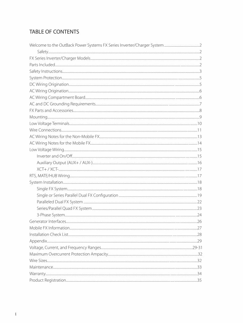
TABLE OF CONTENTS
Welcome to the OutBack Power Systems FX Series Inverter/Charger System .............................................2 Safety .................................................................................................................................................................................................2FX Series Inverter/Charger Models ...........................................................................................................................................2Parts Included................................................................................................................................................................ ........................2Safety Instructions...................................................................................................................................................... .........................3System Protection.................................................................................................................................................... ...........................5DC Wiring Origination....................................................................................................................................... ...............................5AC Wiring Origination........................................................................................................................................ ...............................6AC Wiring Compartment Board................................................................................................................... ..............................6AC and DC Grounding Requirements............................................................................................. .......................................7FX Parts and Accessories................................................................................................................... ..............................................8Mounting........................................................................................................................................................... .......................................9Low Voltage Terminals................................................................................................................. ......................................... .........10Wire Connections........................................................................................................................... ...................................... ............11AC Wiring Notes for the Non-Mobile FX.............................................................................................................................13 AC Wiring Notes for the Mobile FX............................................................................................................................ . ...........14Low Voltage Wiring................................................................................................................................................................... .......15 Inverter and On/Off................................................................................................................................................. .... ..........15 Auxiliary Output (AUX+ / AUX-)......................................................................................................................... . ...........16 XCT+ / XCT-................................................................................................................................................................. ..... ..........17RTS, MATE/HUB Wiring................................................................................................................................................... .... ...........17System Installation.......................................................................................................................................................... ...... ...........18 Single FX System.................................................................................................................................................... ..... ............18 Single or Series Parallel Dual FX Configuration ....................................................................................................19 Paralleled Dual FX System .................................................................................................................................................22 Series/Parallel Quad FX System ......................................................................................................................................23 3-Phase System............................................................................................................................................. ..... ......................24Generator Interfaces............................................................................................................................................ ..... ......................26Mobile FX Information..................................................................................................................................... .... .........................27Installation Check List..................................................................................................................................... ..... ..........................28Appendix............................................................................................................................................................ ........ ...........................29Voltage, Current, and Frequency Ranges.....................................................................................................................29-31Maximum Overcurrent Protection Ampacity...................................................................................................................32Wire Sizes............................................................................................................................................................ ........ ...........................32Maintenance............................................................................................................................................................ ............................33Warranty............................................................................................................................................................... ........ ..........................34Product Registration..................................................................................................................................... ..... .............................35
1
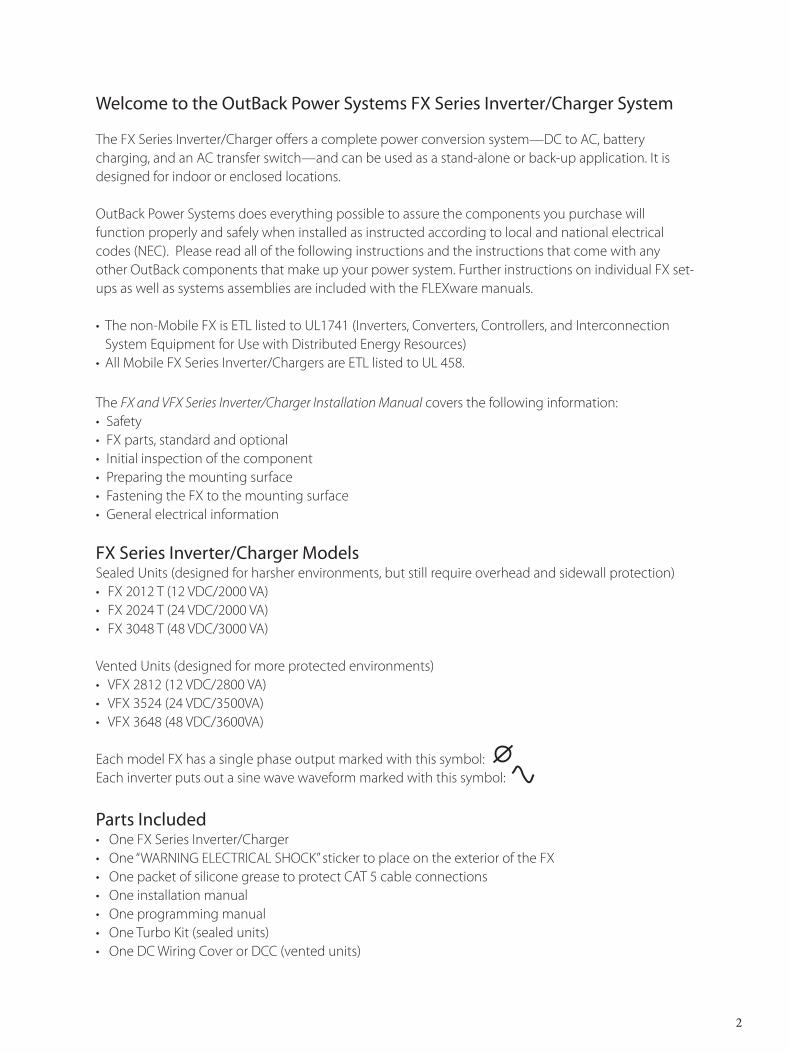
Welcome to the OutBack Power Systems FX Series Inverter/Charger System
The FX Series Inverter/Charger offers a complete power conversion system—DC to AC, battery charging, and an AC transfer switch—and can be used as a stand-alone or back-up application. It is designed for indoor or enclosed locations.
OutBack Power Systems does everything possible to assure the components you purchase will function properly and safely when installed as instructed according to local and national electrical codes (NEC). Please read all of the following instructions and the instructions that come with any other OutBack components that make up your power system. Further instructions on individual FX set-ups as well as systems assemblies are included with the FLEXware manuals.
• The non-Mobile FX is ETL listed to UL1741 (Inverters, Converters, Controllers, and Interconnection System Equipment for Use with Distributed Energy Resources)
• All Mobile FX Series Inverter/Chargers are ETL listed to UL 458.
The FX and VFX Series Inverter/Charger Installation Manual covers the following information:• Safety • FX parts, standard and optional• Initial inspection of the component• Preparing the mounting surface• Fastening the FX to the mounting surface• General electrical information
FX Series Inverter/Charger ModelsSealed Units (designed for harsher environments, but still require overhead and sidewall protection)
FX 2012 T (12 VDC/2000 VA)FX 2024 T (24 VDC/2000 VA)FX 3048 T (48 VDC/3000 VA)
Vented Units (designed for more protected environments)VFX 2812 (12 VDC/2800 VA)VFX 3524 (24 VDC/3500VA)VFX 3648 (48 VDC/3600VA)
Each model FX has a single phase output marked with this symbol:Each inverter puts out a sine wave waveform marked with this symbol:
Parts IncludedOne FX Series Inverter/ChargerOne “WARNING ELECTRICAL SHOCK” sticker to place on the exterior of the FXOne packet of silicone grease to protect CAT 5 cable connectionsOne installation manualOne programming manualOne Turbo Kit (sealed units)One DC Wiring Cover or DCC (vented units)
•••
•••
•••••••
2
R EA D F IR ST !
IMPORTANT SAFETY INSTRUCTIONSRead all instructions and cautionary markings on the FX, the batteries and all appropriate sections of this installation and user manual as well as other component manuals before using the system.
Be cautious around electricity, electrical components, and batteries. Shocks, burns, injury, and even death can occur if an installer comes in contact with electricity.
Install all components and wiring according to national and local electrical and building codes. This includes: • Submitting a plan to the local building department• Passing inspection• Requiring a licensed electrician to do the work when mandated
OutBack Power Systems cannot be responsible for system failure, damages, or injury resulting from improper installation of their products.
Use only the recommended DC and AC wire sizes or greater. Be sure all wires are in good condition.
Install the FX in a dry location, preferably indoors.
• Install the FX in a shaded area out of direct sun light for best operation.• For installations where the FX may be exposed to water spray, a sealed FX must be used and
mounted either with the base down (shelf mounting) or with the AC wiring compartment facing down (wall mounting).
• If mounted with the base down, water cannot be allowed to accumulate around the FX’s base. There is a drainage system on the base of the FX to dispel condensation.
• If submerged, water can enter this drain and cause failure.• The Vented FX (VFX) must be installed in a weather-proof enclosure or enclosed area. It is not designed for exposure to water or excessive wind-blown dust and debris.
3
INITIAL INSPECTIONYour FX is stoutly packaged for secure shipping. Please inspect the packaging and component for damage prior to intallation.
READ FIRST!
Design the battery enclosure to prevent accumulation and concentration of hydrogen gas in “pockets” at the top of the enclosure. Vent the battery compartment from the highest point to the outside. A sloped lid can also be used to direct the flow of hydrogen to the vent opening.
CAUTION
To reduce risk of injury, charge only deep-cycle lead acid, lead antimony, lead calcium, gel cell or absorbed glass mat type rechargeable batteries. Other types of batteries may burst, causing personal injury and damage. Never charge a frozen battery.
PERSONAL PRECAUTIONS
• Someone should be within range of your voice to come to your aid if needed.• Keep plenty of fresh water and soap nearby in case battery acid contacts skin, clothing, or eyes.• Wear complete eye protection. Avoid touching eyes while working near batteries. Wash your hands
with soap and warm water when done.• If battery acid contacts skin or clothing, wash immediately with soap and water. If acid enters an
eye, flood the eye with cool running water at once for at least 15 minutes and get medical attention immediately following.
• Baking soda neutralizes lead acid battery electrolyte. Keep a supply on hand in the area of the batteries.
• NEVER smoke or allow a spark or flame in vicinity of a battery or generator.• Be extra cautious to reduce the risk of dropping a metal tool onto batteries. It could short-circuit the
batteries or other electrical parts can result in fire or explosion.• Remove personal metal items such as rings, bracelets, necklaces, and watches when working with
a battery or other electrical current. A battery can produce a short circuit current high enough to weld a ring or the like to metal, causing severe burns.
4
WARNING: WORKING NEAR LEAD ACID BATTERIES CAN BE DANGEROUS. BATTERIES
GENERATE EXPLOSIVE GASES DURING NORMAL OPERATION.
5
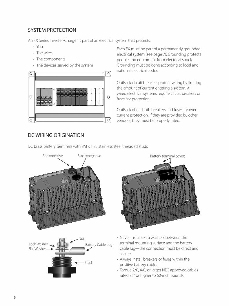
• Never install extra washers between the terminal mounting surface and the battery cable lug—the connection must be direct and secure.
• Always install breakers or fuses within the positive battery cable.
• Torque 2/0, 4/0, or larger NEC approved cables rated 75° or higher to 60-inch pounds.
SYSTEM PROTECTION
An FX Series Inverter/Charger is part of an electrical system that protects:• You• The wires• The components• The devices served by the system
OutBack circuit breakers protect wiring by limiting the amount of current entering a system. All wired electrical systems require circuit breakers or fuses for protection.
OutBack offers both breakers and fuses for over-current protection. If they are provided by other vendors, they must be properly rated.
Each FX must be part of a permanently grounded electrical system (see page 7). Grounding protects people and equipment from electrical shock. Grounding must be done according to local and national electrical codes.
DC WIRING ORIGINATION
DC brass battery terminals with 8M x 1.25 stainless steel threaded studs
Black=negativeRed=positive Battery terminal covers
Battery Cable LugLock WasherFlat Washer
Nut
Stud
6
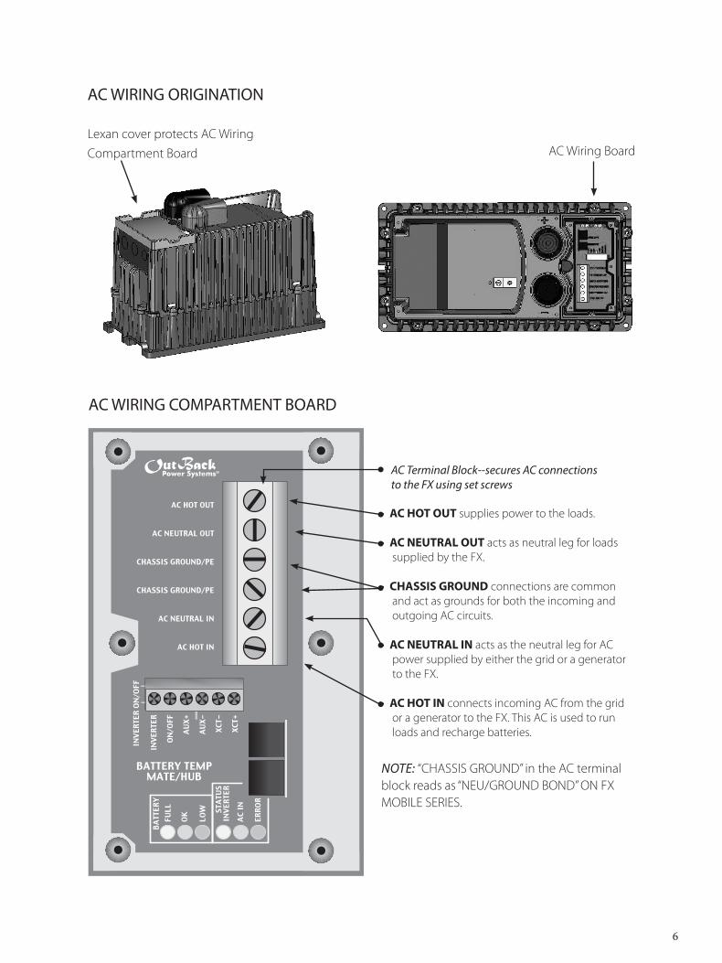
AC WIRING ORIGINATION
Lexan cover protects AC Wiring Compartment Board
AC WIRING COMPARTMENT BOARD
• AC HOT OUT supplies power to the loads.
• AC NEUTRAL OUT acts as neutral leg for loads supplied by the FX.
• CHASSIS GROUND connections are common and act as grounds for both the incoming and outgoing AC circuits.
• AC NEUTRAL IN acts as the neutral leg for AC power supplied by either the grid or a generator to the FX.
• AC HOT IN connects incoming AC from the grid or a generator to the FX. This AC is used to run loads and recharge batteries.
Note: “CHASSIS GROUND” in the AC terminal block reads as “NEU/GROUND BOND” ON FX MOBILE SERIES.
����������
��������������
�����������������
�����������������
�������������
���������
����
���
����
��
��� ��
���
���
���
���
�����
�����
��������������������
�����
�����
���
��
�����
���
����
��
����
����
����
����
AC terminal Block--secures AC connections to the FX using set screws
AC Wiring Board
7
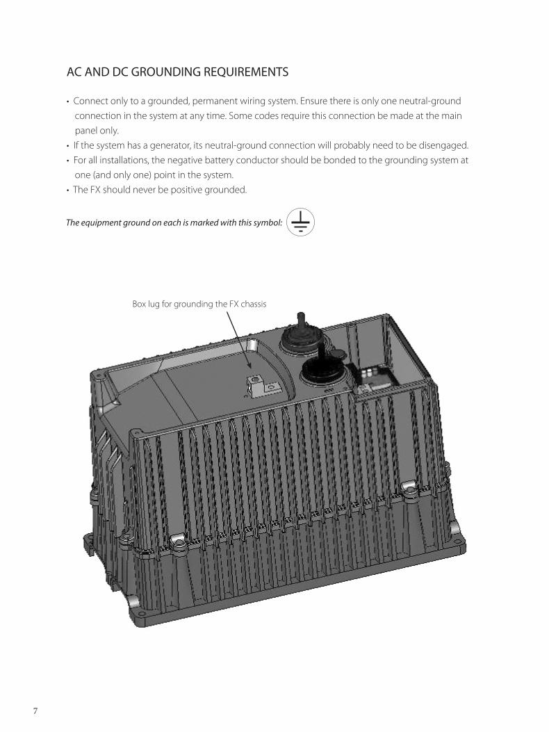
AC AND DC GROUNDING REQUIREMENTS
• Connect only to a grounded, permanent wiring system. Ensure there is only one neutral-ground connection in the system at any time. Some codes require this connection be made at the main panel only.
• If the system has a generator, its neutral-ground connection will probably need to be disengaged.• For all installations, the negative battery conductor should be bonded to the grounding system at
one (and only one) point in the system. • The FX should never be positive grounded.
the equipment ground on each is marked with this symbol:
Box lug for grounding the FX chassis
8
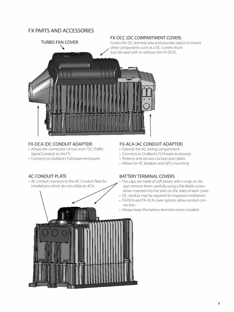
FX-ACA (AC CONDUIT ADAPTER) • Extends the AC wiring compartment • Connects to OutBack’s FLEXware enclosures• Protects and secures conduit and cables• Allows for AC breakers and GFCI mounting
FX-DCC (DC COMPARTMENT COVER)Covers the DC terminal area and provides space to mount other components such as a DC current shunt (can be used with or without the FX-DCA).
FX PARTS AND ACCESSORIES
BATTERY TERMINAL COVERS• The caps are made of stiff plastic with a snap-on de-
sign; remove them carefully using a flat-blade screw-driver inserted into the slots on the sides of each cover.
• DC conduit may be required for exposed installations.• FX-DCA and FX-ACA cover options allow conduit con-
nection.• Always keep the battery terminal covers installed.
AC CONDUIT PLATE• AC conduit connects to the AC Conduit Plate for
installations which do not utilize an ACA.
FX-DCA (DC CONDUIT ADAPTER)• Allows the connection of two-inch TSC (Traffic
Signal Conduit) to the FX• Connects to OutBack’s FLEXware enclosures
TURBO FAN COVER
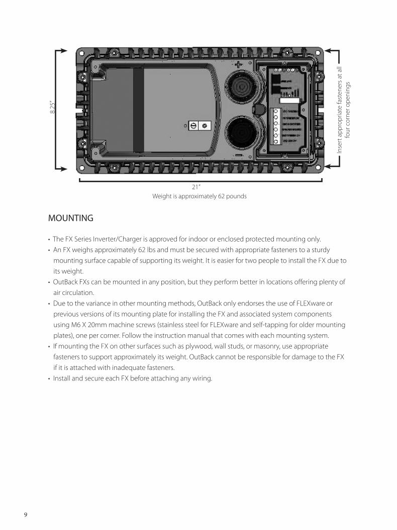
MOUNTING
• The FX Series Inverter/Charger is approved for indoor or enclosed protected mounting only.• An FX weighs approximately 62 lbs and must be secured with appropriate fasteners to a sturdy
mounting surface capable of supporting its weight. It is easier for two people to install the FX due to its weight.
• OutBack FXs can be mounted in any position, but they perform better in locations offering plenty of air circulation.
• Due to the variance in other mounting methods, OutBack only endorses the use of FLEXware or previous versions of its mounting plate for installing the FX and associated system components using M6 X 20mm machine screws (stainless steel for FLEXware and self-tapping for older mounting plates), one per corner. Follow the instruction manual that comes with each mounting system.
• If mounting the FX on other surfaces such as plywood, wall studs, or masonry, use appropriate fasteners to support approximately its weight. OutBack cannot be responsible for damage to the FX if it is attached with inadequate fasteners.
• Install and secure each FX before attaching any wiring.
21”Weight is approximately 62 pounds
8.25
”
9
Inse
rt a
ppro
pria
te fa
sten
ers a
t all
four
cor
ner o
peni
ngs
10
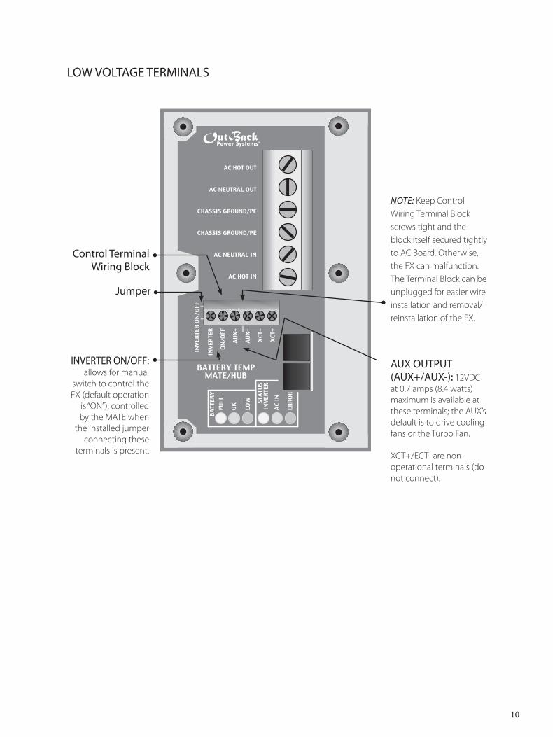
LOW VOLTAGE TERMINALS
Control Terminal Wiring Block
Note: Keep Control Wiring Terminal Block screws tight and the block itself secured tightly to AC Board. Otherwise, the FX can malfunction. The Terminal Block can be unplugged for easier wire installation and removal/reinstallation of the FX.
AUX OUTPUT (AUX+/AUX-): 12VDC at 0.7 amps (8.4 watts) maximum is available at these terminals; the AUX’s default is to drive cooling fans or the Turbo Fan.
XCT+/ECT- are non-operational terminals (do not connect).
INVERTER ON/OFF: allows for manual
switch to control the FX (default operation
is “ON”); controlled by the MATE when
the installed jumper connecting these
terminals is present.
Jumper
����������
��������������
�����������������
�����������������
�������������
���������
����
���
����
��
��� ��
���
���
���
���
�����
�����
��������������������
�����
�����
���
��
�����
���
����
��
����
����
����
����
AC
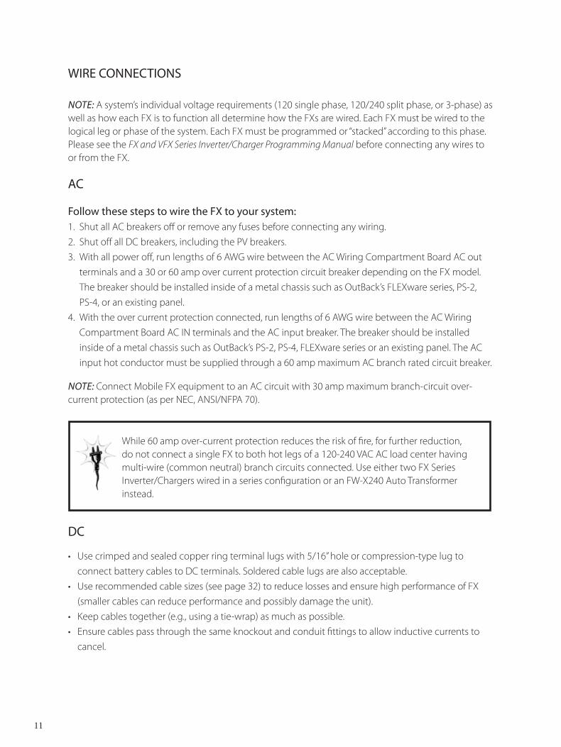
Follow these steps to wire the FX to your system: 1. Shut all AC breakers off or remove any fuses before connecting any wiring. 2. Shut off all DC breakers, including the PV breakers.3. With all power off, run lengths of 6 AWG wire between the AC Wiring Compartment Board AC out
terminals and a 30 or 60 amp over current protection circuit breaker depending on the FX model. The breaker should be installed inside of a metal chassis such as OutBack’s FLEXware series, PS-2,
PS-4, or an existing panel. 4. With the over current protection connected, run lengths of 6 AWG wire between the AC Wiring
Compartment Board AC IN terminals and the AC input breaker. The breaker should be installed inside of a metal chassis such as OutBack’s PS-2, PS-4, FLEXware series or an existing panel. The AC input hot conductor must be supplied through a 60 amp maximum AC branch rated circuit breaker.
DC
• Use crimped and sealed copper ring terminal lugs with 5/16” hole or compression-type lug to connect battery cables to DC terminals. Soldered cable lugs are also acceptable.
• Use recommended cable sizes (see page 32) to reduce losses and ensure high performance of FX (smaller cables can reduce performance and possibly damage the unit).
• Keep cables together (e.g., using a tie-wrap) as much as possible.• Ensure cables pass through the same knockout and conduit fittings to allow inductive currents to
cancel.
WIRE CONNECTIONS
Note: A system’s individual voltage requirements (120 single phase, 120/240 split phase, or 3-phase) as well as how each FX is to function all determine how the FXs are wired. Each FX must be wired to the logical leg or phase of the system. Each FX must be programmed or “stacked” according to this phase. Please see the FX and VFX Series Inverter/Charger Programming Manual before connecting any wires to or from the FX.
While 60 amp over-current protection reduces the risk of fire, for further reduction, do not connect a single FX to both hot legs of a 120-240 VAC AC load center having multi-wire (common neutral) branch circuits connected. Use either two FX Series Inverter/Chargers wired in a series configuration or an FW-X240 Auto Transformer instead.
Note: Connect Mobile FX equipment to an AC circuit with 30 amp maximum branch-circuit over-current protection (as per NEC, ANSI/NFPA 70).
11
12
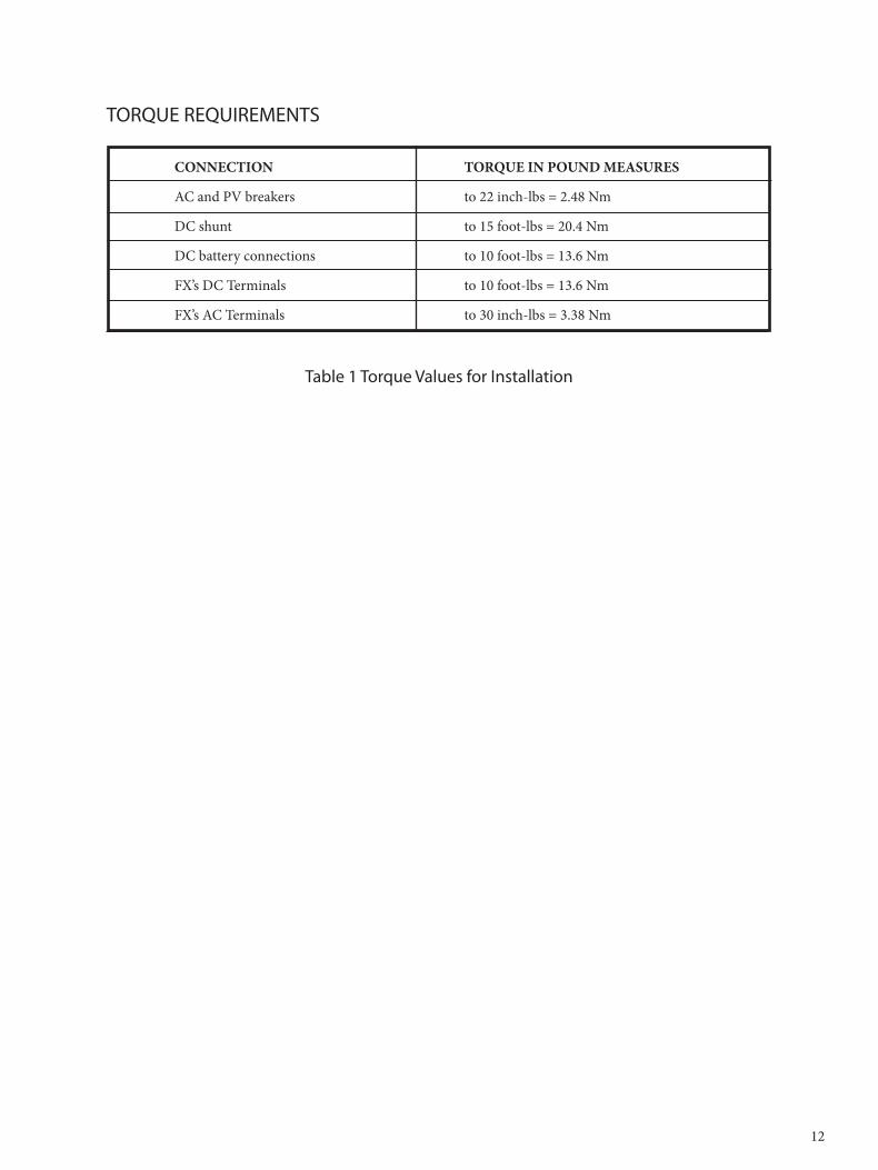
TORQUE REQUIREMENTS
CONNECTION TORQUE IN POUND MEASURES
AC and PV breakers to 22 inch-lbs = 2.48 Nm
DC shunt to 15 foot-lbs = 20.4 Nm
DC battery connections to 10 foot-lbs = 13.6 Nm
FX’s DC Terminals to 10 foot-lbs = 13.6 Nm
FX’s AC Terminals to 30 inch-lbs = 3.38 Nm
Table 1 Torque Values for Installation
13
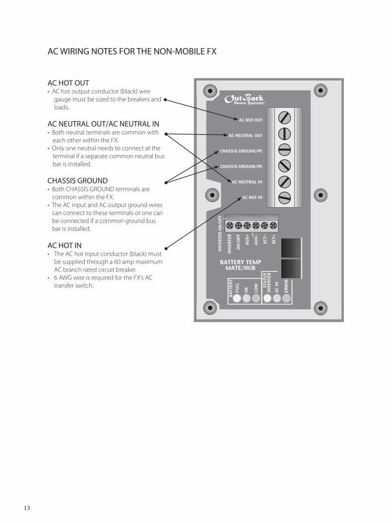
AC WIRING NOTES FOR THE NON-MOBILE FX
AC HOT OUT• AC hot output conductor (black) wire
gauge must be sized to the breakers and loads.
AC NEUTRAL OUT/AC NEUTRAL IN• Both neutral terminals are common with
each other within the FX. • Only one neutral needs to connect at the
terminal if a separate common neutral bus bar is installed.
CHASSIS GROUND• Both CHASSIS GROUND terminals are
common within the FX.• The AC input and AC output ground wires
can connect to these terminals or one can be connected if a common ground bus bar is installed.
AC HOT IN • The AC hot input conductor (black) must
be supplied through a 60 amp maximum AC branch rated circuit breaker.
• 6 AWG wire is required for the FX’s AC transfer switch.
����������
��������������
�����������������
�����������������
�������������
���������
����
���
����
��
��� ��
���
���
���
���
�����
�����
��������������������
�����
�����
���
��
�����
���
����
��
����
����
����
����
����������
��������������
��������������
���������������
�������������
���������
����
��
���
�����
���
�������������������
��������
�����
�����
���
��
�����
���
����
��
����
����
����
����
� ��� � � � � �� � � �
�� � � � � � � � �
� � � � � � � �� � � � � � � �
�������������
��������������
�����
14
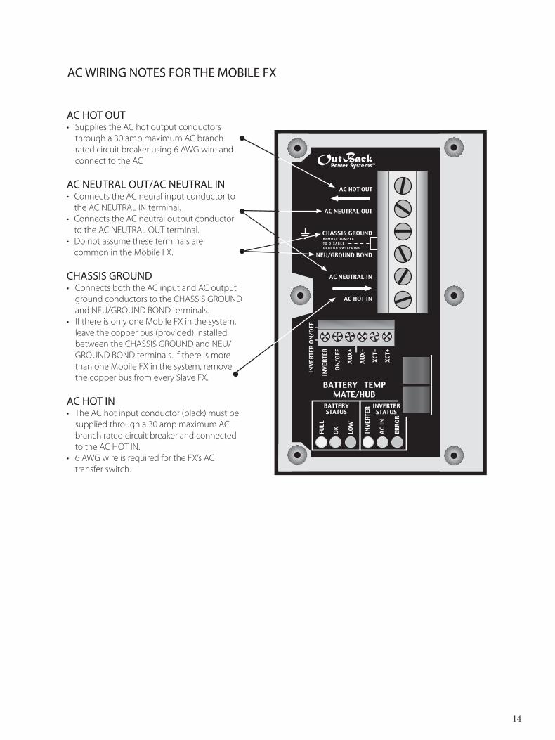
AC HOT OUT• Supplies the AC hot output conductors
through a 30 amp maximum AC branch rated circuit breaker using 6 AWG wire and connect to the AC
AC NEUTRAL OUT/AC NEUTRAL IN• Connects the AC neural input conductor to
the AC NEUTRAL IN terminal.• Connects the AC neutral output conductor
to the AC NEUTRAL OUT terminal.• Do not assume these terminals are common in the Mobile FX.
CHASSIS GROUND• Connects both the AC input and AC output
ground conductors to the CHASSIS GROUND and NEU/GROUND BOND terminals.
• If there is only one Mobile FX in the system, leave the copper bus (provided) installed between the CHASSIS GROUND and NEU/GROUND BOND terminals. If there is more than one Mobile FX in the system, remove the copper bus from every Slave FX.
AC HOT IN • The AC hot input conductor (black) must be
supplied through a 30 amp maximum AC branch rated circuit breaker and connected to the AC HOT IN.
• 6 AWG wire is required for the FX’s AC transfer switch.
AC WIRING NOTES FOR THE MOBILE FX
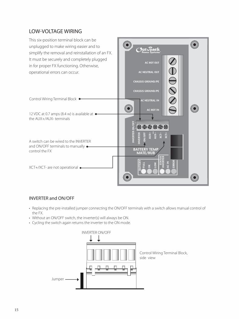
LOW-VOLTAGE WIRING
A switch can be wired to the INVERTER and ON/OFF terminals to manually control the FX
XCT+/XCT- are not operational
12 VDC at 0.7 amps (8.4 w) is available at the AUX+/AUX- terminals
This six-position terminal block can be unplugged to make wiring easier and to simplify the removal and reinstallation of an FX. It must be securely and completely plugged in for proper FX functioning. Otherwise, operational errors can occur.
INVERTER and ON/OFF
• Replacing the pre-installed jumper connecting the ON/OFF terminals with a switch allows manual control of the FX.
• Without an ON/OFF switch, the inverter(s) will always be ON. • Cycling the switch again returns the inverter to the ON mode.
Control Wiring Terminal Block, side view
INVERTER ON/OFF
15
Jumper
����������
��������������
�����������������
�����������������
�������������
���������
����
���
����
��
��� ��
���
���
���
���
�����
�����
��������������������
�����
�����
���
��
�����
���
����
��
����
����
����
����
Control Wiring Terminal Block
Prior to installing an ON/OFF switch, if the FX’s AC output is off, check that the jumper is present and well-connected before installing a switch. You want to confirm the system is
in good working order. Suggested switches include Push On/Push Off Switches (275-671, 275-1555, 275-1565, 275-617, and 275-011) from Radio Shack.
Should you decide to install an OutBack MATE at a later date, bear in mind the installed switch overrides the control provided by the MATE if the switch is set to OFF. If the switch is set to ON, the MATE will function normally and control the inverter(s).
• When a system is ordered with a MATE, the MATE handles all FX ON/OFF functions.
AUXILIARY OUTPUT ( AUX + / AUX - )
The Auxiliary output system uses the AUX + and AUX – terminals. It is programmed through the MATE to do a variety of tasks:
• The default use for these terminals drives the OutBack FX Turbo Kit or DC12-FAN fan for external cooling.
Note: These terminals should not be connected to any type of DC load greater than one amp.
• The FX includes internal electronic over-current protection for the AUX 12 VDC output circuit which auto resets if it is short-circuited. No additional fuses are required.
• For automatic or advanced generator start functions, the Auxiliary Output can drive a 12V automo-tive relay for the two-wire starting circuitry of a generator. OutBack recommends a good quality gold-plated relay.
Note: OutBack Power Systems does not support three-wire start generators; however, a three-wire to two-wire conversion kit is available from an electronic control manufacturer such as Atkinson Electron-ics.
XCT + / XCT - These terminals are not operational at this time.
16
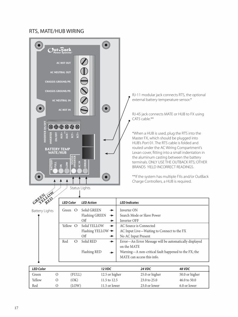
RTS, MATE/HUB WIRING
RJ-11 modular jack connects RTS, the optional external battery temperature sensor.*
RJ-45 jack connects MATE or HUB to FX using CAT5 cable.**
*When a HUB is used, plug the RTS into the Master FX, which should be plugged into HUB’s Port 01. The RTS cable is folded and routed under the AC Wiring Compartment’s Lexan cover, fitting into a small indentation in the aluminum casting between the battery terminals. ONLY USE THE OUTBACK RTS; OTHER BRANDS YIELD INCORRECT READINGS.
**If the system has multiple FXs and/or OutBack Charge Controllers, a HUB is required.
����������
��������������
�����������������
�����������������
�������������
���������
����
���
����
��
��� ��
���
���
���
���
�����
�����
��������������������
�����
�����
���
��
�����
���
����
��
����
����
����
����
LED Color 12 VDC 24 VDC 48 VDC
Green O (FULL) 12.5 or higher 25.0 or higher 50.0 or higherYellow O (OK) 11.5 to 12.5 23.0 to 25.0 46.0 to 50.0Red O (LOW) 11.5 or lower 23.0 or lower 6.0 or lower
LED Color LED Action LED Indicates
Green O Solid GREEN Inverter ON Flashing GREEN Search Mode or Slave Power Off Inverter OFFYellow O Solid YELLOW AC Source is Connected Flashing YELLOW AC Input Live—Waiting to Connect to the FX Off No AC Input PresentRed O Solid RED Error—An Error Message will be automatically displayed on the MATE Flashing RED Warning—A non-critical fault happened to the FX; the MATE can access this info.
17
Status Lights
Battery Lights
GREEN
YELLOW
RED
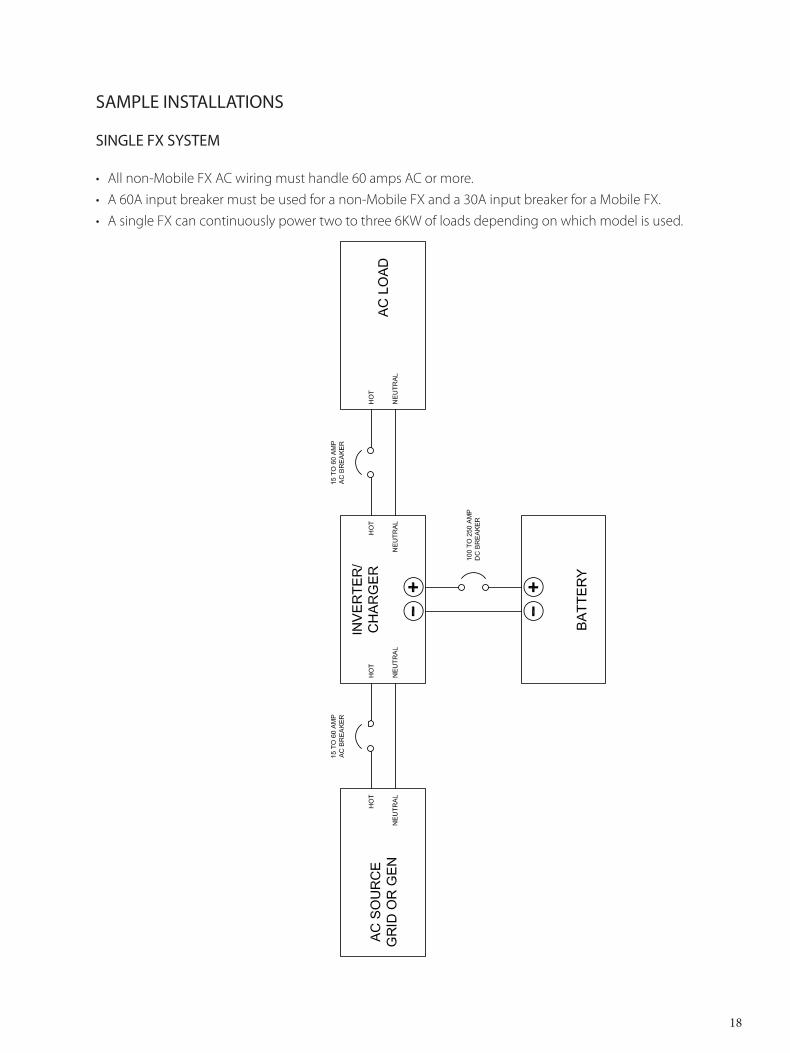
SAMPLE INSTALLATIONS
SINGLE FX SYSTEM
• All non-Mobile FX AC wiring must handle 60 amps AC or more.• A 60A input breaker must be used for a non-Mobile FX and a 30A input breaker for a Mobile FX.• A single FX can continuously power two to three 6KW of loads depending on which model is used.
18
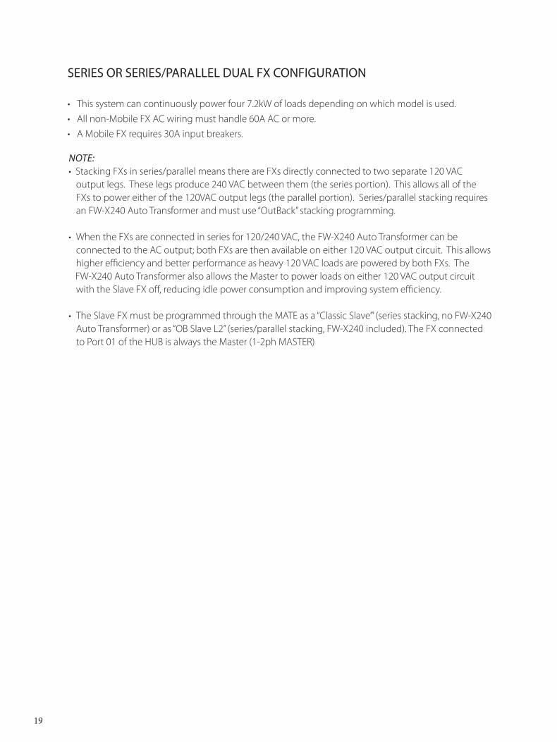
SERIES OR SERIES/PARALLEL DUAL FX CONFIGURATION
• This system can continuously power four 7.2kW of loads depending on which model is used. • All non-Mobile FX AC wiring must handle 60A AC or more.• A Mobile FX requires 30A input breakers.
Note:• Stacking FXs in series/parallel means there are FXs directly connected to two separate 120 VAC
output legs. These legs produce 240 VAC between them (the series portion). This allows all of the FXs to power either of the 120VAC output legs (the parallel portion). Series/parallel stacking requires an FW-X240 Auto Transformer and must use “OutBack” stacking programming.
• When the FXs are connected in series for 120/240 VAC, the FW-X240 Auto Transformer can be connected to the AC output; both FXs are then available on either 120 VAC output circuit. This allows higher efficiency and better performance as heavy 120 VAC loads are powered by both FXs. The
FW-X240 Auto Transformer also allows the Master to power loads on either 120 VAC output circuit with the Slave FX off, reducing idle power consumption and improving system efficiency.
• The Slave FX must be programmed through the MATE as a “Classic Slave’” (series stacking, no FW-X240 Auto Transformer) or as “OB Slave L2” (series/parallel stacking, FW-X240 included). The FX connected to Port 01 of the HUB is always the Master (1-2ph MASTER)
19
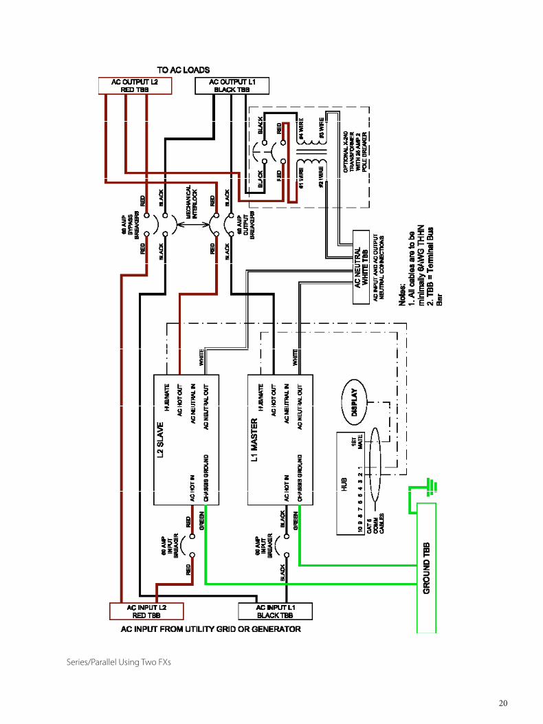
Series/Parallel Using Two FXs
20

Series/Parallel Using Four FXs
21
22
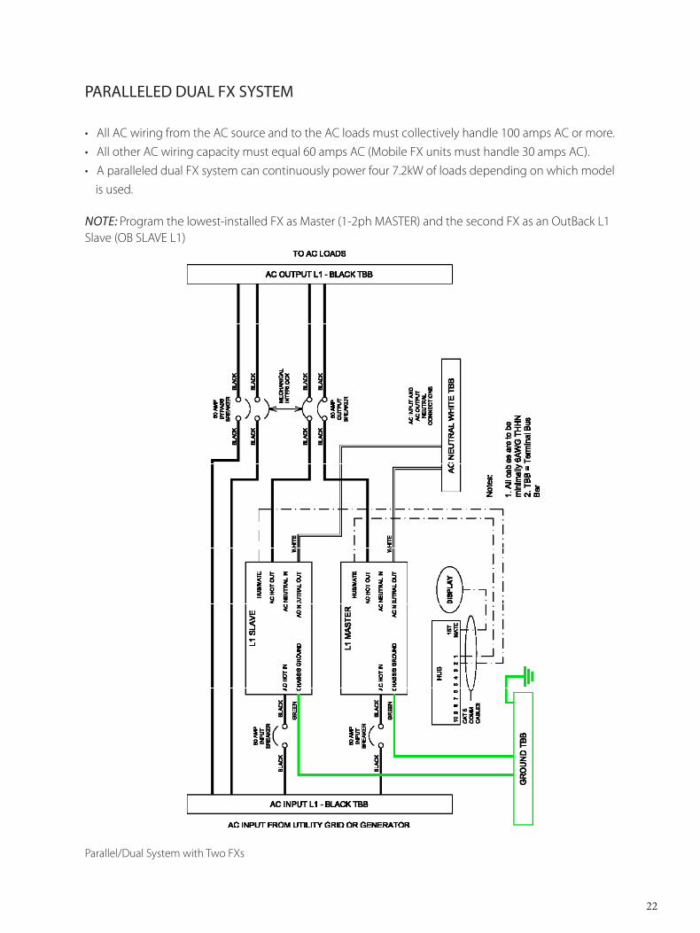
PARALLELED DUAL FX SYSTEM
• All AC wiring from the AC source and to the AC loads must collectively handle 100 amps AC or more. • All other AC wiring capacity must equal 60 amps AC (Mobile FX units must handle 30 amps AC).• A paralleled dual FX system can continuously power four 7.2kW of loads depending on which model
is used. Note: Program the lowest-installed FX as Master (1-2ph MASTER) and the second FX as an OutBack L1 Slave (OB SLAVE L1)
Parallel/Dual System with Two FXs

23
SERIES/PARALLEL QUAD FX SYSTEM
• All AC wiring from the AC source and to the AC loads must collectively handle 120 amps AC or more. • All other AC wiring must handle a capacity of 60 amps AC (Mobile FX AC wiring must handle 30
amps).• This system can continuously power eight 14.4kW of loads depending on which model is used.• Connecting more power than the continuous rating of the FX may cause breakers to trip or the FX
to shut off its AC output. • A HUB, MATE, and FW-X240 must be connected to successfully stack these FXs in series/parallel.
Notes: • Program the lowest-installed FX as the Master (1-2ph MASTER), the first Slave as an Outback L1 Slave
(OB Slave L1), and the second and third Slaves as OutBack L2 Slaves (OB SLAVE L2) as shown in the MATE User’s Manual.
• An FW-X240 Auto Transformer must be used when three or more FXs are series stacked.
When the FXs are connected in series for 120/240 VAC, the FW-X240 Auto Transformer can be connected to the two AC output legs to provide all FX capacity to either of the 120 VAC output circuits. This allows higher efficiency and better performance as heavy 120 VAC loads are powered by all the FXs.
The FW-X240 Auto Transformer also allows the Master to power loads on either of the 120 VAC output circuits with the Slave off. This reduces the idle power consumption and improves the system efficiency.
PARALLELED QUAD FX SYSTEM
• All AC wiring from the AC source and to the AC loads must collectively handle 200 amps AC or more. • All other non-Mobile FX Series Inverter/Charger models’ AC wiring must handle a capacity of 60
amps AC. • This system can continuously power eight 14.4kW of loads depending on which model is used. • Connecting more power than the continuous rating of the FX may cause breakers to trip or the FX
to shut off its AC output.
Notes: Program the lowest-installed FX as Master (1-2ph MASTER) and the three remaining FXs as OutBack L1 Slaves (OB SLAVE L1)
24
3-PHASE FX SYSTEM
• This system produces 120VAC per phase and 208VAC from phase to phase. There can only be one FX per phase on a 3-phase system.
• The non-Mobile AC wiring from the AC source and to the AC loads must handle 60 amps AC. • All other non-Mobile AC wiring must handle a capacity of 60 amps AC; Mobile must handle 30 amps
AC.• This system can power continuously up to 10.8kW of loads depending on which model is used.• Connecting more power than the continuous rating of the FX may cause breakers to trip or the FX
to shut off its AC output. • The jumper in the HUB must be moved for 3-phase configuration (please see the HUB Installation
and User Guide).
Note: Program the bottom FX as Master (3ph MASTER) and the two lower FXs as 3-phase Slaves (3ph SLAVE). Keep the phases in order: phase one is connected to the FX programmed L1; phase two is connected to L2; and phase three to L3 (or phases A, B, and C to inverters A, B, and C).
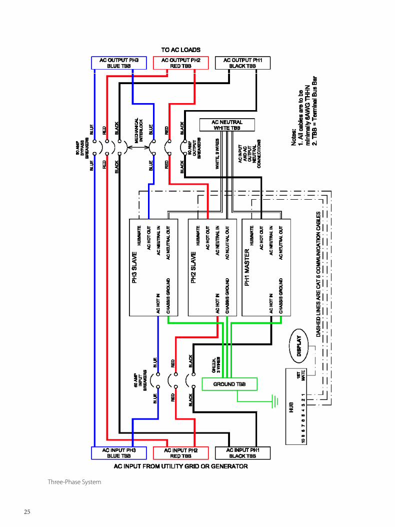
Three-Phase System
25
26
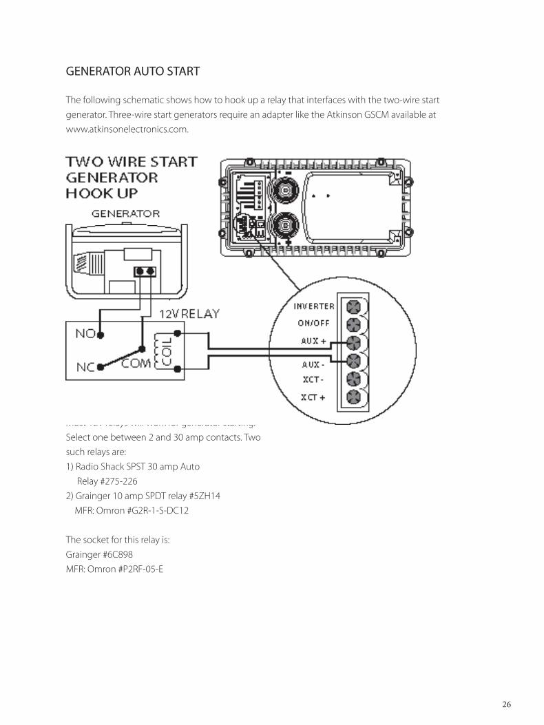
GENERATOR AUTO START
The following schematic shows how to hook up a relay that interfaces with the two-wire start generator. Three-wire start generators require an adapter like the Atkinson GSCM available atwww.atkinsonelectronics.com.
Most 12V relays will work for generator starting. Select one between 2 and 30 amp contacts. Two such relays are:1) Radio Shack SPST 30 amp Auto Relay #275-2262) Grainger 10 amp SPDT relay #5ZH14 MFR: Omron #G2R-1-S-DC12 The socket for this relay is:Grainger #6C898MFR: Omron #P2RF-05-E
27
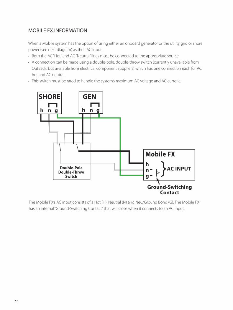
MOBILE FX INFORMATION
When a Mobile system has the option of using either an onboard generator or the utility grid or shore power (see next diagram) as their AC input:• Both the AC “Hot” and AC “Neutral” lines must be connected to the appropriate source. • A connection can be made using a double-pole, double-throw switch (currently unavailable from
OutBack, but available from electrical component suppliers) which has one connection each for AC hot and AC neutral.
• This switch must be rated to handle the system’s maximum AC voltage and AC current.
The Mobile FX’s AC input consists of a Hot (H), Neutral (N) and Neu/Ground Bond (G). The Mobile FX has an internal “Ground-Switching Contact” that will close when it connects to an AC input.
SHORE
h n g h n g
GEN
Double-PoleDouble-Throw
Switch
Mobile FXhng
AC INPUT
Ground-Switching Contact
28
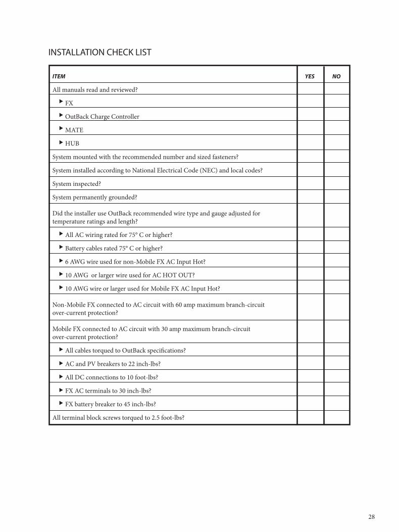
INSTALLATION CHECK LIST
ITEM YES NO
All manuals read and reviewed?
FX
OutBack Charge Controller
MATE
HUB
System mounted with the recommended number and sized fasteners?
System installed according to National Electrical Code (NEC) and local codes?
System inspected?
System permanently grounded?
Did the installer use OutBack recommended wire type and gauge adjusted for temperature ratings and length?
All AC wiring rated for 75° C or higher?
Battery cables rated 75° C or higher?
6 AWG wire used for non-Mobile FX AC Input Hot?
10 AWG or larger wire used for AC HOT OUT?
10 AWG wire or larger used for Mobile FX AC Input Hot?
Non-Mobile FX connected to AC circuit with 60 amp maximum branch-circuitover-current protection?
Mobile FX connected to AC circuit with 30 amp maximum branch-circuit over-current protection?
All cables torqued to OutBack specifications?
AC and PV breakers to 22 inch-lbs?
All DC connections to 10 foot-lbs?
FX AC terminals to 30 inch-lbs?
FX battery breaker to 45 inch-lbs?
All terminal block screws torqued to 2.5 foot-lbs?
29
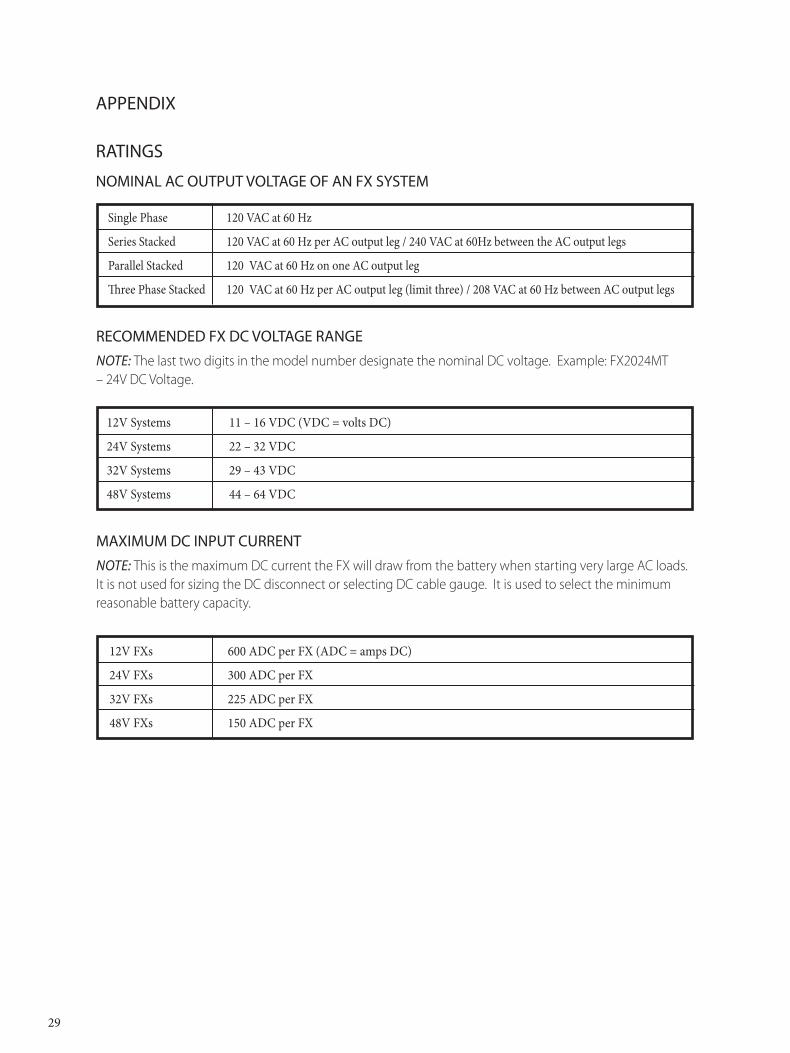
APPENDIX
RATINGS
NOMINAL AC OUTPUT VOLTAGE OF AN FX SYSTEM
Single Phase 120 VAC at 60 Hz
Series Stacked 120 VAC at 60 Hz per AC output leg / 240 VAC at 60Hz between the AC output legs
Parallel Stacked 120 VAC at 60 Hz on one AC output leg
Three Phase Stacked 120 VAC at 60 Hz per AC output leg (limit three) / 208 VAC at 60 Hz between AC output legs
RECOMMENDED FX DC VOLTAGE RANGENote: The last two digits in the model number designate the nominal DC voltage. Example: FX2024MT – 24V DC Voltage.
12V Systems 11 – 16 VDC (VDC = volts DC)
24V Systems 22 – 32 VDC
32V Systems 29 – 43 VDC
48V Systems 44 – 64 VDC
MAXIMUM DC INPUT CURRENTNote: This is the maximum DC current the FX will draw from the battery when starting very large AC loads. It is not used for sizing the DC disconnect or selecting DC cable gauge. It is used to select the minimum reasonable battery capacity.
12V FXs 600 ADC per FX (ADC = amps DC)
24V FXs 300 ADC per FX
32V FXs 225 ADC per FX
48V FXs 150 ADC per FX
30
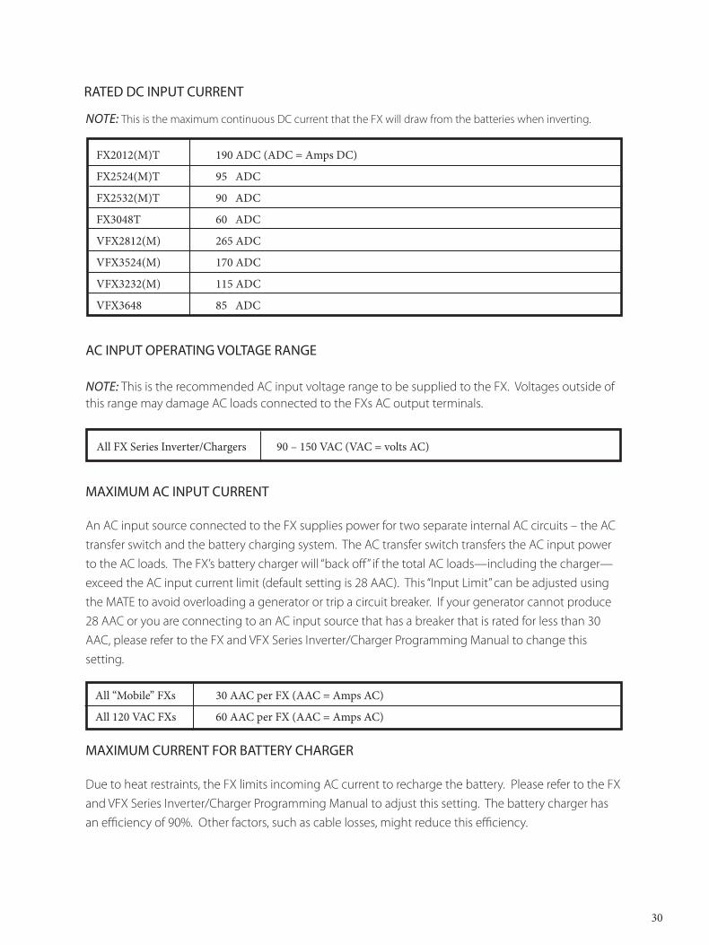
Note: This is the maximum continuous DC current that the FX will draw from the batteries when inverting.
FX2012(M)T 190 ADC (ADC = Amps DC)
FX2524(M)T 95 ADC
FX2532(M)T 90 ADC
FX3048T 60 ADC
VFX2812(M) 265 ADC
VFX3524(M) 170 ADC
VFX3232(M) 115 ADC
VFX3648 85 ADC
AC INPUT OPERATING VOLTAGE RANGE
Note: This is the recommended AC input voltage range to be supplied to the FX. Voltages outside of this range may damage AC loads connected to the FXs AC output terminals.
All FX Series Inverter/Chargers 90 – 150 VAC (VAC = volts AC)
MAXIMUM AC INPUT CURRENT
An AC input source connected to the FX supplies power for two separate internal AC circuits – the AC transfer switch and the battery charging system. The AC transfer switch transfers the AC input power to the AC loads. The FX’s battery charger will “back off” if the total AC loads—including the charger—exceed the AC input current limit (default setting is 28 AAC). This “Input Limit” can be adjusted using the MATE to avoid overloading a generator or trip a circuit breaker. If your generator cannot produce 28 AAC or you are connecting to an AC input source that has a breaker that is rated for less than 30 AAC, please refer to the FX and VFX Series Inverter/Charger Programming Manual to change this setting.
All “Mobile” FXs 30 AAC per FX (AAC = Amps AC)
All 120 VAC FXs 60 AAC per FX (AAC = Amps AC)
MAXIMUM CURRENT FOR BATTERY CHARGER
Due to heat restraints, the FX limits incoming AC current to recharge the battery. Please refer to the FX and VFX Series Inverter/Charger Programming Manual to adjust this setting. The battery charger has an efficiency of 90%. Other factors, such as cable losses, might reduce this efficiency.
RATED DC INPUT CURRENT
31
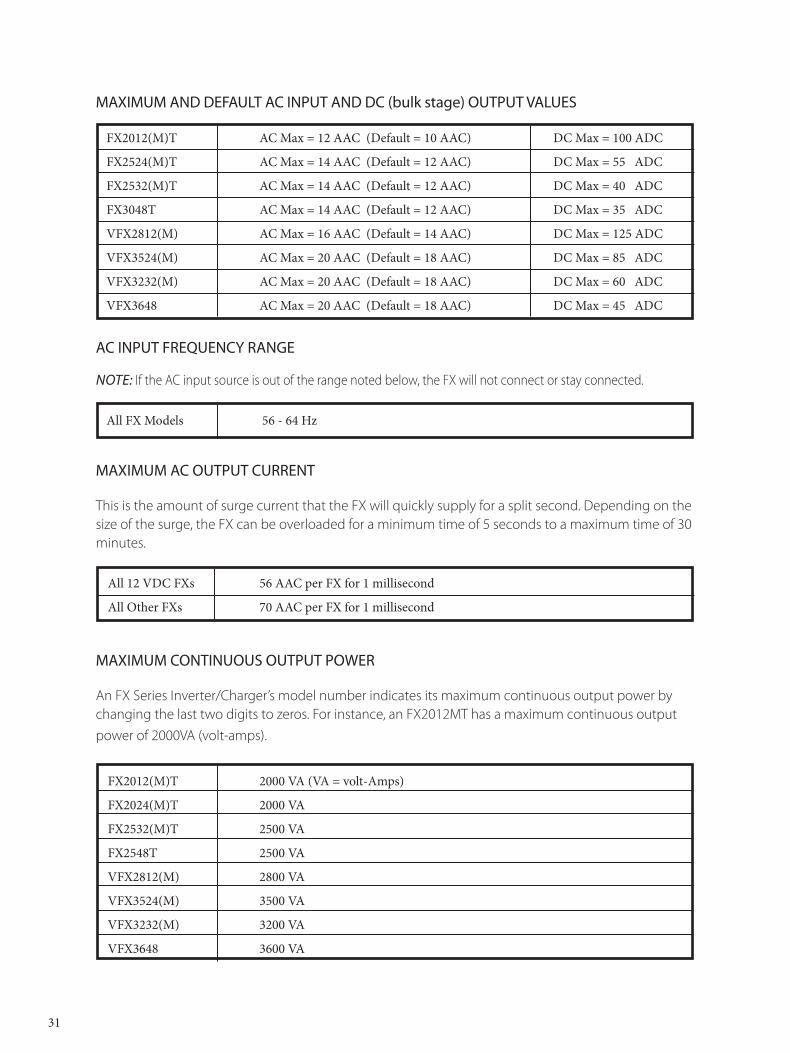
FX2012(M)T AC Max = 12 AAC (Default = 10 AAC) DC Max = 100 ADC
FX2524(M)T AC Max = 14 AAC (Default = 12 AAC) DC Max = 55 ADC
FX2532(M)T AC Max = 14 AAC (Default = 12 AAC) DC Max = 40 ADC
FX3048T AC Max = 14 AAC (Default = 12 AAC) DC Max = 35 ADC
VFX2812(M) AC Max = 16 AAC (Default = 14 AAC) DC Max = 125 ADC
VFX3524(M) AC Max = 20 AAC (Default = 18 AAC) DC Max = 85 ADC
VFX3232(M) AC Max = 20 AAC (Default = 18 AAC) DC Max = 60 ADC
VFX3648 AC Max = 20 AAC (Default = 18 AAC) DC Max = 45 ADC
AC INPUT FREQUENCY RANGE
Note: If the AC input source is out of the range noted below, the FX will not connect or stay connected.
All FX Models 56 - 64 Hz
MAXIMUM AC OUTPUT CURRENT
This is the amount of surge current that the FX will quickly supply for a split second. Depending on the size of the surge, the FX can be overloaded for a minimum time of 5 seconds to a maximum time of 30 minutes.
All 12 VDC FXs 56 AAC per FX for 1 millisecond
All Other FXs 70 AAC per FX for 1 millisecond
MAXIMUM CONTINUOUS OUTPUT POWER
An FX Series Inverter/Charger’s model number indicates its maximum continuous output power by changing the last two digits to zeros. For instance, an FX2012MT has a maximum continuous output power of 2000VA (volt-amps).
FX2012(M)T 2000 VA (VA = volt-Amps)
FX2024(M)T 2000 VA
FX2532(M)T 2500 VA
FX2548T 2500 VA
VFX2812(M) 2800 VA
VFX3524(M) 3500 VA
VFX3232(M) 3200 VA
VFX3648 3600 VA
MAXIMUM AND DEFAULT AC INPUT AND DC (bulk stage) OUTPUT VALUES

MODEL AMPACITY DC BREAKER DC FUSE
FX2012(M)T 260 amps OBDC-250 Class T-400 (Mobile Only)
FX2024(M)T 175 amps OBDC-175 Class T-300 (Mobile Only)
FX2532(M)T 175 amps OBDC-175 Class T-300 (Mobile Only)
FX2548T 100 amps OBDC-100 Not Recommended
VFX2812(M) 260 amps OBDC-250 Class T-400 (Mobile Only)
VFX3524(M) 260 amps OBDC-250 Class T-400 (Mobile Only)
VFX3232(M) 175 amps OBDC-175 Class T-300 (Mobile Only)
VFX3648 175 amps OBDC-175 Not Recommended
32
WIRE SIZES
The following chart contains information on wire sizes, the DC resistance of the wires and the corresponding diameters and areas of these wires. This information can be used to calculate the voltage drop of the wires or to find an equivalent wire size.
SIZE DC CROSS-SECTIONAL AREA APPROXIMATE DIAMETER (AWG) Resistance in Ohms (1000 feet) INCHES MILLIMETERS INCHES MILLIMETERS
14 3.14 .0032 2.08 .078 1.9812 1.98 .0051 3.31 .101 2.5710 1.24 .0082 5.26 .126 3.208 0.78 .0130 8.37 .162 4.116 0.50 .0206 13.30 .215 5.464 0.31 .0328 21.15 .269 6.832 0.19 .0521 33.62 .337 8.561 0.15 .0657 42.41 .376 9.551/0 0.12 .0829 53.50 .423 10.742/0 0.10 .1045 67.43 .508 12.903/0 0.08 .1318 85.01 .576 14.634/0 0.06 .1662 107.20 .645 16.38
MAXIMUM OVERCURRENT PROTECTION AMPACITY
This rating specifies the proper overcurrent protection ampacity.
• OBDC breakers are panel-mount circuit breakers. • Class T DC fuses are terminal-mounted and should always be used in conjuncture with a disconnect mechanism. • FXs used in home installations should use properly sized DC circuit breakers. • A DC breaker includes both overcurrent protection and disconnect capability. • OutBack Power Systems recommends Class T fuses for marine installations where a DC disconnect is not required.
MAINTENANCE
If damaged or malfunctioning, the FX should be repaired by a qualified user, installer, or service center following OutBack Power Systems’ instructions and guidelines. Please contact your energy dealer for assistance. Incorrect repairs and/or reassembly risks malfunction, electric shock or fire.
For routine, user-approved maintenance:• Disconnect all circuit breakers and related electrical connections before doing any cleaning or
adjustments. • Solar modules may produce hazardous voltages when exposed to light; cover them with opaque
material before servicing any connected equipment or service at night.• If a remote or automatic generator start system is used, disable the automatic starting circuit and/
or disconnect the generator from its starting battery while servicing it to prevent starting while servicing.
33
WARRANTY
OutBack Power Systems Two Year Limited Warranty
OutBack Power Systems Inc. warrants that the products it manufactures will be free from defects in materials and workmanship for a period of two (2) years subject to the conditions set forth below.
The limited warranty is extended to the original user and is transferable. The limited warranty term begins on the date of invoice to the original user of the product. The limited warranty does not apply to any product or part thereof damaged by a) alteration or disassembly, b) accident or abuse, c) corrosion, d) lightning, e) reverse polarity, f ) repair or service provided by an unauthorized repair facility, g) operation or installation contrary to instructions pertaining to the product.
OutBack Power Systems’ liability for any defective product or any part thereof shall be limited to the repair or replacement of the product, at OutBack Power Systems’ discretion. OutBack Power Systems does not warrant or guarantee the workmanship performed by any person or firm installing its products.
THIS LIMITED WARRANTY GIVES YOU SPECIFIC LEGAL RIGHTS, AND YOU MAY ALSO HAVE OTHER RIGHTS THAT VARY FROM STATE TO STATE (OR JURISDICTION TO JURISDICTION). OUTBACK POWER SYSTEMS’ RESPONSIBILITY FOR MALFUNCTIONS AND DEFECTS IN HARDWARE IS LIMITED TO REPAIR AND REPLACEMENT AS SET FORTH IN THIS LIMITED WARRANTY STATEMENT. ALL EXPRESS AND IMPLIED WARRANTIES FOR THE PRODUCT, INCLUDING BUT NOT LIMITED TO ANY IMPLIED WARRANTIES OF AND CONDITIONS OF MERCHANTABILITY AND FITNESS FOR A PARTICULAR PURPOSE, ARE LIMITED IN DURATION TO THE LIMITED WARRANTY PERIOD SET FORTH ABOVE AND NO WARRANTIES, WHETHER EXPRESS OR IMPLIED, WILL APPLY AFTER SUCH PERIOD. SOME STATES (OR JURISDICTIONS) DO NOT ALLOW LIMITATIONS ON HOW LONG AN IMPLIED WARRANTY LASTS, SO THE ABOVE LIMITATION MAY NOT APPLY TO YOU.
OUTBACK POWER SYSTEMS DOES NOT ACCEPT LIABILITY BEYOND THE REMEDIES SET FORTH IN THIS LIMITED WARRANTY STATEMENT OR LIABILITY FOR INCIDENTAL OR CONSEQUENTIAL DAMAGES, INCLUDING WITHOUT LIMITATION ANY LIABILITY FOR PRODUCTS NOT BEING AVAILABLE FOR USE. SOME STATES (OR JURISDICTIONS) DO NOT ALLOW THE EXCLUSION OR LIMITATION OF INCIDENTAL OR CONSEQUENTIAL DAMAGES, SO THE ABOVE EXCLUSION OR LIMITATION MAY NOT APPLY TO YOU.
During the two year period beginning on the invoice date, OutBack Power Systems will repair or replace products covered under this limited warranty that are returned to OutBack Power Systems’ facility or to an OutBack Power Systems authorized repair facility, or that are repaired on site by an OutBack Power Systems authorized repair technician. To request limited warranty service, you must contact OutBack Power Systems at 360-435-6030 within the limited warranty period. If limited warranty service is required, OutBack Power Systems will issue a Return Material Authorization (RMA) Number. Mark the outside of the package with the RMA number and include a copy of the purchase invoice in the package. You must ship the products back to OutBack Power Systems in their original or equivalent packaging, prepay shipping charges, and insure the shipment or accept the risk of loss or damage during shipment. OutBack Power Systems will ship the repaired or replacement products to you freight prepaid if you use an address in the continental United States, where applicable. Shipments to other locations will be made freight collect.
34
35
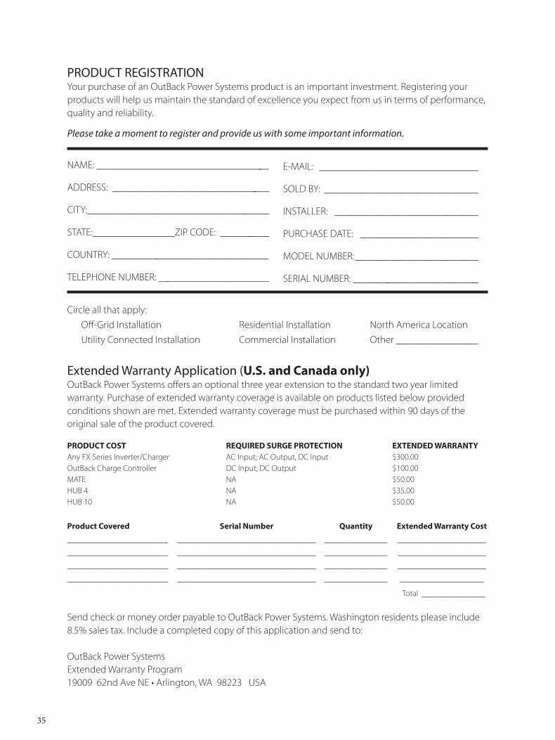
PRODUCT REGISTRATIONYour purchase of an OutBack Power Systems product is an important investment. Registering your products will help us maintain the standard of excellence you expect from us in terms of performance, quality and reliability. Please take a moment to register and provide us with some important information.
NAME: __________________________________
ADDRESS: _______________________________
CITY:____________________________________
STATE:________________ZIP CODE: __________
COUNTRY: _______________________________
TELEPHONE NUMBER: ______________________
E-MAIL: _______________________________
SOLD BY: ______________________________
INSTALLER: ____________________________
PURCHASE DATE: _______________________
MODEL NUMBER: ________________________
SERIAL NUMBER: _________________________ _
Circle all that apply: Off-Grid Installation Residential Installation North America Location Utility Connected Installation Commercial Installation Other ________________
Extended Warranty Application (U.S. and Canada only)OutBack Power Systems offers an optional three year extension to the standard two year limited warranty. Purchase of extended warranty coverage is available on products listed below provided conditions shown are met. Extended warranty coverage must be purchased within 90 days of the original sale of the product covered.
PRODUCT COST REQUIRED SURGE PROTECTION EXTENDED WARRANTYAny FX Series Inverter/Charger AC Input; AC Output, DC Input $300.00 OutBack Charge Controller DC Input; DC Output $100.00 MATE NA $50.00 HUB 4 NA $35.00 HUB 10 NA $50.00
Product Covered Serial Number Quantity Extended Warranty Cost
________________________ _________________________________ _______________ _____________________
________________________ _________________________________ _______________ _____________________
________________________ _________________________________ _______________ _____________________
________________________ _________________________________ _______________ ____________________
Total _______________ Send check or money order payable to OutBack Power Systems. Washington residents please include 8.5% sales tax. Include a completed copy of this application and send to:
OutBack Power SystemsExtended Warranty Program19009 62nd Ave NE • Arlington, WA 98223 USA


European Sales OfficeBarcelona, ESPAÑA(+34) 600.843.845
19009 62nd Avenue NEArlington, WA 98223 USA(+1) 360.435.6030
www.outbackpower.com 900-0083-01-00 REV A


