
9 - 1
9 F-CIM Lab
9.1 Foreword F-CIM (Control Interconnection Modules) provides a method of optimizing the controller’s standard functionality. This method is more flexible than the FCS, but not as extensive and flexible as the F-TRAN. But F-CIM is easier to program than F-TRAN. As we explained before, F-CIM programming is done by building the strategy using building-blocks from the Module library. The Module library is a collection of predefined function blocks.
It is more powerful than the FCS method because each strategy can consist of up to 100 blocks, the order of execution can be specified by the user, and many of the blocks are reusable.
It is also possible for the user to make custom function blocks and add them to the Module Library.
Creating a custom F-CIM module is not in the scope of this training coarse and will not be covered.
9.2 Objectives In this lab we will introduce F-CIM programming and implement a simple control strategy using F-CIM. After completing this lab, you should know how to
• Create a F-CIM control strategy using F-CIM function modules described in the Customization Guide
• Enter an F-CIM control strategy using the faceplate keys
• Create an F-CIM control strategy using the MicroTools Graphical Editor
• Download an F-CIM control strategy using MicroTools
Training Manual F-CIM Lab
9 - 2
9.3 F-CIM Programming 9.3.1 Module Library
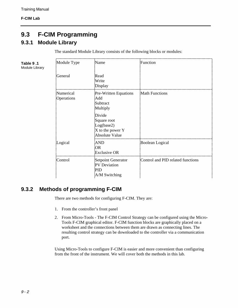
The standard Module Library consists of the following blocks or modules:
Table 9 .1 Module Library
Module Type Name Function
General
Read Write Display
Numerical Operations
Pre-Written Equations Add Subtract Multiply
Divide Square root Log(base2) X to the power Y Absolute Value
Math Functions
Logical
AND OR Exclusive OR
Boolean Logical
Control
Setpoint Generator PV Deviation PID A/M Switching
Control and PID related functions
9.3.2 Methods of programming F-CIM There are two methods for configuring F-CIM. They are:
1. From the controller’s front panel
2. From Micro-Tools - The F-CIM Control Strategy can be configured using the Micro-Tools F-CIM graphical editor. F-CIM function blocks are graphically placed on a worksheet and the connections between them are drawn as connecting lines. The resulting control strategy can be downloaded to the controller via a communication port.
Using Micro-Tools to configure F-CIM is easier and more convenient than configuring from the front of the instrument. We will cover both the methods in this lab.

Training Manual
F-CIM Lab
9 - 3
9.3.3 Steps of Programming F-CIM The steps involved in programming the controller using F-CIM are:
1. Define the control strategy to be implemented
2. Select the function blocks that can be used for implementing the defined control strategy
3. Draw the function block diagram using these function blocks
4. Enter data on a work sheet for the function blocks
Each function block has its associated inputs and outputs. In general there are 4 inputs to each block. These inputs are labeled as follows:
• A, B and C – these inputs are configurable
• Sn-1 – this input is the output of the previous step (previous function block)
The F-CIM program is executed in steps. The 53MC5000 controller can execute 100 F-CIM program steps. Step number range from 0 to 99. In general, each Function Block requires one step.
Training Manual F-CIM Lab
9 - 4
9.4 Instructions 9.4.1 Part 1 – F-CIM Programming from front face
1. Define the process control strategy to be implemented first: The strategy involves a single loop PID control. We will add the following in addition to the PID control:
• Enable Output tracking based on closure of Contact Input 1. We will assume that the output tracking signal comes from Analog Input 2
• Enable Setpoint tracking of Process Variable when the controller is not in Auto mode. We will assume that the PV comes from Analog input 0
• Disable Remote setpoint on closure of Contact input 0. We will assume that the remote setpoint input comes from Analog Input 1.
2. Select the F-CIM modules: We will use the following F-CIM modules
1. READ – for reading ANI-1 for remote setpoint
2. SP0 – Setpoint generator for Loop0
3. DEV0 – Deviation Calculation for Loop0
4. PID0 – PID for loop0
5. A/M0 – Auto Manual selection for Loop0
6. WRITE – for writing the output of A/M0 to Analog Output 0
7. DISPLAY – for displaying the loop parameters
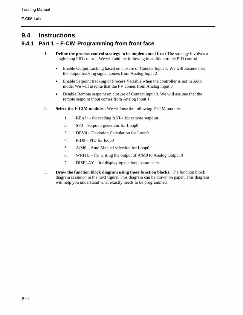
3. Draw the function block diagram using these function blocks: The function block diagram is shown in the next figure. This diagram can be drawn on paper. This diagram will help you understand what exactly needs to be programmed.
Training Manual
F-CIM Lab
9 - 5
Figure 9 .1. F-CIM Program Block Diagram
SP 0F-CIM 044
RSP RE STV SWSPT
SP
SP PV
DV
DEV 0F-CIM 047
DV
CO
PID 0F-CIM 041
RF CTC
CO
OUT
A/M 0F-CIM 043
OTV SWOTVAE
READF-CIM 086
WRITEF-CIM 087
AUT
B
ANO 0
ANI 2
CCI 1
ANI 0
CCI 0
CCI 0
“1”
“1.0”
“1.0”
DISPLAYF-CIM 022
PROGRAM REFERENCED I/O
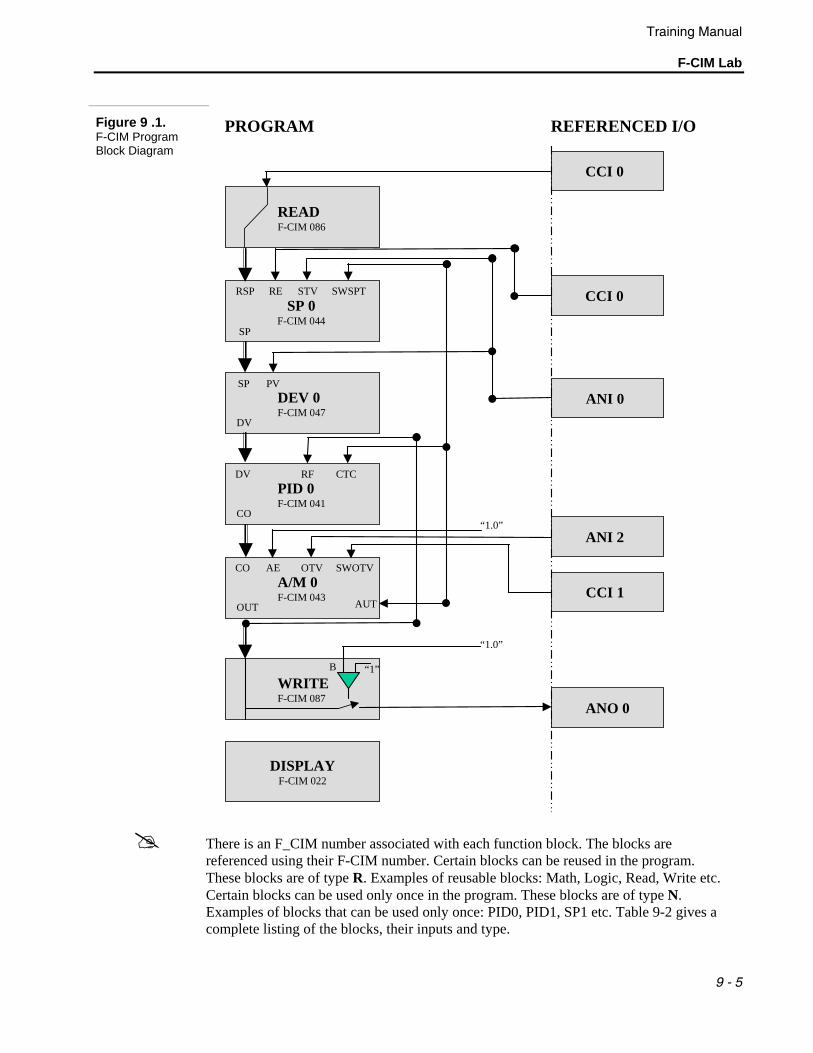
There is an F_CIM number associated with each function block. The blocks are referenced using their F-CIM number. Certain blocks can be reused in the program. These blocks are of type R. Examples of reusable blocks: Math, Logic, Read, Write etc. Certain blocks can be used only once in the program. These blocks are of type N. Examples of blocks that can be used only once: PID0, PID1, SP1 etc. Table 9-2 gives a complete listing of the blocks, their inputs and type.
Training Manual F-CIM Lab
9 - 6
Inputs Table 9 .2 F-CIM Directory
Block Name
F-CIM Number Sn-1 AIN BIN CIN Type
Description
ADD 99 * C X X R ADD
SUB 98 C C X R SUBTRACT
MUL 97 * C X X R MULTIPLY
DIV 96 C C X R DIVIDE
SQRT 95 * X X X R SQUARE ROOT
LOG2 94 * X X X R LOG2
YPOWX 93 * C C X R Y TO THE POWER OF X
ABS 92 * X X X R ABSOLUTE VALUE
LINV 91 * X X X R LOGICAL INVERSION
LAND 90 * Y X X R LOGICAL AND
LOR 89 * Y X X R LOGICAL OR
LXOR 88 * Y X X R LOGICAL EXCLUSIVE OR
WRITE 87 * Y Y X R WRITE PARAM TO A, POINTER P
READ 86 Y X X R READ PARAM A TO X
Ax+B 85 * C C X R (Ax) + B
SWITCH 84 * Y Y X R IF (BIN) ; X= AIN
COMP 83 * Y Y Y R HIGH/LOW COMPARATOR W/HYSTERESIS
J-K 82 * Y X X R LOGIC J - K LATCH
SP0 44 * Y Y Y N SET POINT GENERATOR FOR LOOP 0
PID0 41 * X Y Y N PID CALCULATION FOR LOOP 0
AM0 43 * Y Y Y N AUTO MANUAL SELECTOR FOR LOOP 0
DEV0 47 * Y X X N DEVIATION CALCULATION FOR LOOP 0
SP1 54 * Y X X N SET POINT GENERATOR FOR LOOP 1
PID1 51 * X Y Y N PID CALCULATION FOR LOOP 1
AM1 53 * Y Y Y N AUTO MANUAL SELECTOR FOR LOOP 1
DEV1 57 * Y X X N DEVIATION CALCULATION FOR LOOP 1
SP2 64 * Y Y Y N SET POINT GENERATOR FOR LOOP 2
Training Manual
F-CIM Lab
9 - 7
Inputs Table 9 .2 F-CIM Directory – Continued
Block Name
F-CIM Number Sn-1 AIN BIN CIN Type
Description
PID2 61 * X Y Y N PID CALCULATION FOR LOOP 2
AM2 63 * Y Y Y N AUTO MANUAL SELECTOR FOR LOOP 2
DEV2 67 * Y X X N DEVIATION CALCULATION FOR LOOP 2
SP3 74 * Y Y Y N SET POINT GENERATOR FOR LOOP 3
PID3 71 * X Y Y N PID CALCULATION FOR LOOP 3
AM3 73 * Y Y X N AUTO MANUAL SELECTOR FOR LOOP 3
DEV3 77 * Y X X N DEVIATION CALCULATION FOR LOOP 3
MATHA 100 * Y Y Y N MATH BLOCK
MATHB 101 * Y Y Y N MATH BLOCK
MATHC 102 * Y Y Y N MATH BLOCK
MATHD 103 * Y Y Y N MATH BLOCK
MATHE 104 * Y Y Y N MATH BLOCK
MATHF 105 * Y Y Y N MATH BLOCK
MATHG 106 * Y Y Y N MATH BLOCK
MATHH 107 * Y Y Y N MATH BLOCK
EMATHA 52 * Y Y Y N EXTENDED MATH BLOCK
EMATHB 62 * Y Y Y N EXTENDED MATH BLOCK
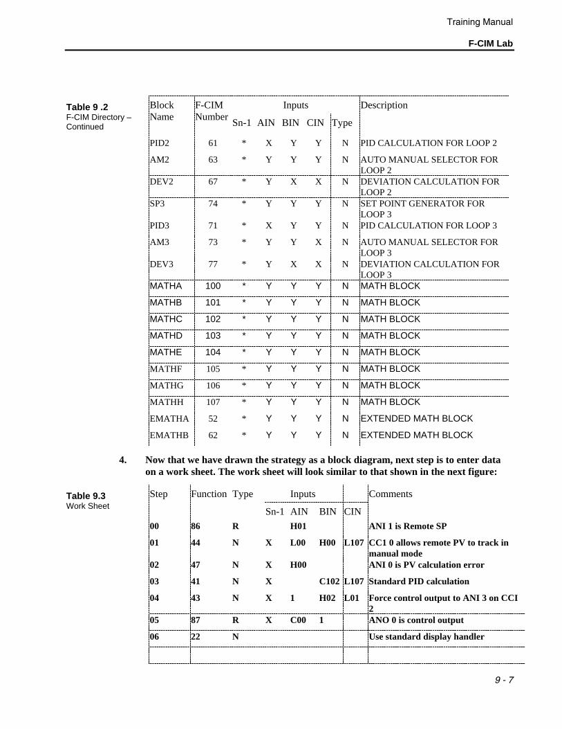
4. Now that we have drawn the strategy as a block diagram, next step is to enter data on a work sheet. The work sheet will look similar to that shown in the next figure:
Function Inputs Table 9.3 Work Sheet
Step
Type
Sn-1 AIN BIN CIN
Comments
00 86 R H01 ANI 1 is Remote SP
01 44 N X L00 H00 L107 CC1 0 allows remote PV to track in manual mode
02 47 N X H00 ANI 0 is PV calculation error
03 41 N X C102 L107 Standard PID calculation
04 43 N X 1 H02 L01 Force control output to ANI 3 on CCI 2
05 87 R X C00 1 ANO 0 is control output
06 22 N Use standard display handler

Training Manual F-CIM Lab
9 - 8
5. So far it has been only paperwork. The next step is to enter the function block inputs and parameters into the database of the controller.
Enter PROGRAM mode: Press the Dot button to enter the engineering mode. This may require you to press the Dot button more than once. The engineering mode will display a line of text at the bottom of the screen. The line of text will contain the word DISPLAY, CONFIGURE or PROGRAM. Press the F2 button until PROGRAM is displayed at the bottom as shown in the next figure:
Figure 9.2. Program Mode
• Now press F3 to enter the program mode.
• 53MC5000 controllers can be configured for password protection. The controllers you are using should not have any password requirements. When you are working on controller in normal plant operations, passwords may be required. If you are prompted for a password, the password must be entered before you may continue.
• The display will show either VIEW, BUILD, or ERASE at the bottom of the screen as shown in the next screen.
You can perform three options in the F-CIM Program mode:
1. View – This mode is for viewing the step results of an F-CIM program
2. Erase – This mode is for erasing an existing F-CIM program
3. Build – This mode is for creating a new F-CIM program or modifying an existing F-CIM program.
Training Manual
F-CIM Lab
9 - 9
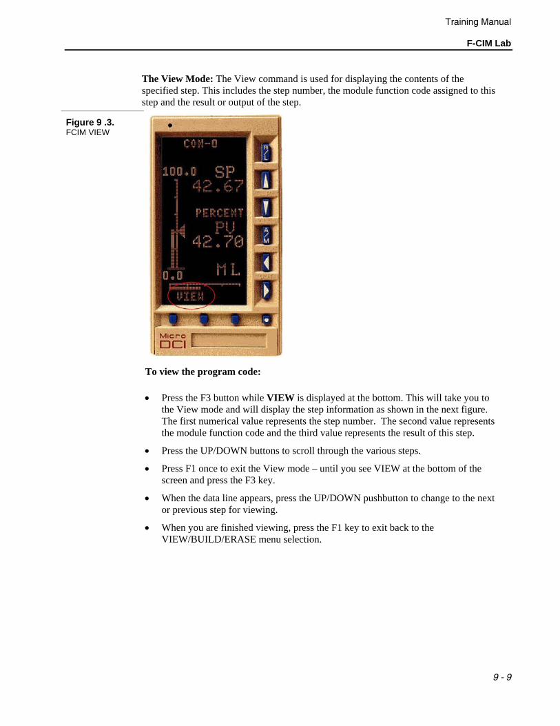
The View Mode: The View command is used for displaying the contents of the specified step. This includes the step number, the module function code assigned to this step and the result or output of the step.
Figure 9 .3. FCIM VIEW
To view the program code:
• Press the F3 button while VIEW is displayed at the bottom. This will take you to the View mode and will display the step information as shown in the next figure. The first numerical value represents the step number. The second value represents the module function code and the third value represents the result of this step.
• Press the UP/DOWN buttons to scroll through the various steps.
• Press F1 once to exit the View mode – until you see VIEW at the bottom of the screen and press the F3 key.
• When the data line appears, press the UP/DOWN pushbutton to change to the next or previous step for viewing.
• When you are finished viewing, press the F1 key to exit back to the VIEW/BUILD/ERASE menu selection.
Training Manual F-CIM Lab
9 - 10
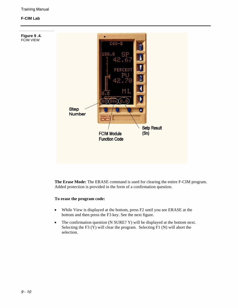
Figure 9 .4. FCIM VIEW
The Erase Mode: The ERASE command is used for clearing the entire F-CIM program. Added protection is provided in the form of a confirmation question.
To erase the program code:
• While View is displayed at the bottom, press F2 until you see ERASE at the bottom and then press the F3 key. See the next figure.
• The confirmation question (N SURE? Y) will be displayed at the bottom next. Selecting the F3 (Y) will clear the program. Selecting F1 (N) will abort the selection.
Training Manual
F-CIM Lab
9 - 11
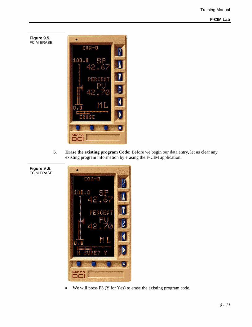
Figure 9.5. FCIM ERASE
6. Erase the existing program Code: Before we begin our data entry, let us clear any existing program information by erasing the F-CIM application.
Figure 9 .6. FCIM ERASE
• We will press F3 (Y for Yes) to erase the existing program code.
Training Manual F-CIM Lab
9 - 12
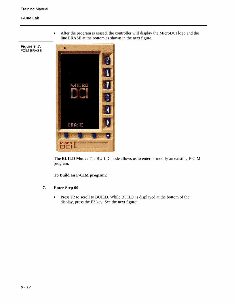
• After the program is erased, the controller will display the MicroDCI logo and the line ERASE at the bottom as shown in the next figure.
Figure 9 .7. FCIM ERASE
The BUILD Mode: The BUILD mode allows us to enter or modify an existing F-CIM program.
To Build an F-CIM program:
7. Enter Step 00
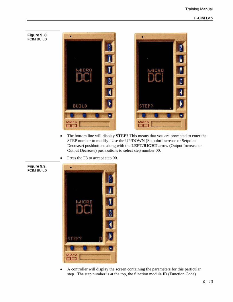
• Press F2 to scroll to BUILD. While BUILD is displayed at the bottom of the display, press the F3 key. See the next figure:
Training Manual
F-CIM Lab
9 - 13
Figure 9 .8. FCIM BUILD
• The bottom line will display STEP? This means that you are prompted to enter the
STEP number to modify. Use the UP/DOWN (Setpoint Increase or Setpoint Decrease) pushbuttons along with the LEFT/RIGHT arrow (Output Increase or Output Decrease) pushbuttons to select step number 00.
• Press the F3 to accept step 00.
Figure 9.9. FCIM BUILD
• A controller will display the screen containing the parameters for this particular
step. The step number is at the top, the function module ID (Function Code)
Training Manual F-CIM Lab
9 - 14
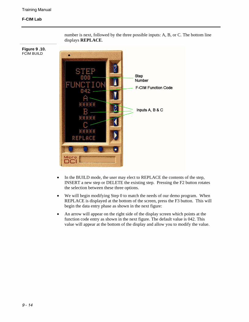
number is next, followed by the three possible inputs: A, B, or C. The bottom line displays REPLACE.
Figure 9 .10. FCIM BUILD
• In the BUILD mode, the user may elect to REPLACE the contents of the step,
INSERT a new step or DELETE the existing step. Pressing the F2 button rotates the selection between these three options.
• We will begin modifying Step 0 to match the needs of our demo program. When REPLACE is displayed at the bottom of the screen, press the F3 button. This will begin the data entry phase as shown in the next figure:
• An arrow will appear on the right side of the display screen which points at the function code entry as shown in the next figure. The default value is 042. This value will appear at the bottom of the display and allow you to modify the value.
Training Manual
F-CIM Lab
9 - 15
Figure 9 .11. FCIM BUILD
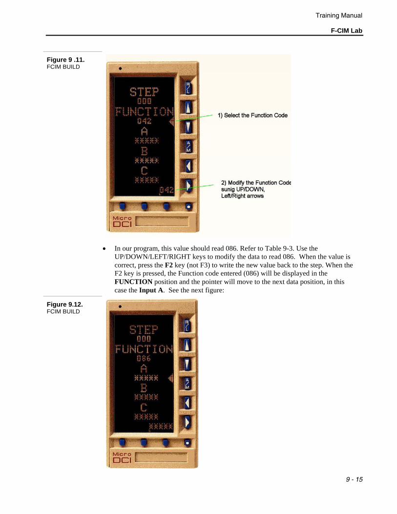
• In our program, this value should read 086. Refer to Table 9-3. Use the
UP/DOWN/LEFT/RIGHT keys to modify the data to read 086. When the value is correct, press the F2 key (not F3) to write the new value back to the step. When the F2 key is pressed, the Function code entered (086) will be displayed in the FUNCTION position and the pointer will move to the next data position, in this case the Input A. See the next figure:
Figure 9.12. FCIM BUILD
Training Manual F-CIM Lab
9 - 16
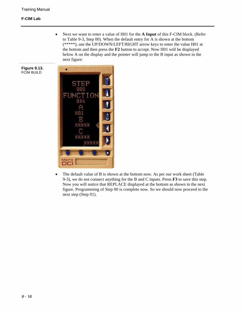
• Next we want to enter a value of H01 for the A Input of this F-CIM block. (Refer to Table 9-3, Step 00). When the default entry for A is shown at the bottom (*****), use the UP/DOWN/LEFT/RIGHT arrow keys to enter the value H01 at the bottom and then press the F2 button to accept. Now H01 will be displayed below A on the display and the pointer will jump to the B input as shown in the next figure:
Figure 9.13. FCIM BUILD
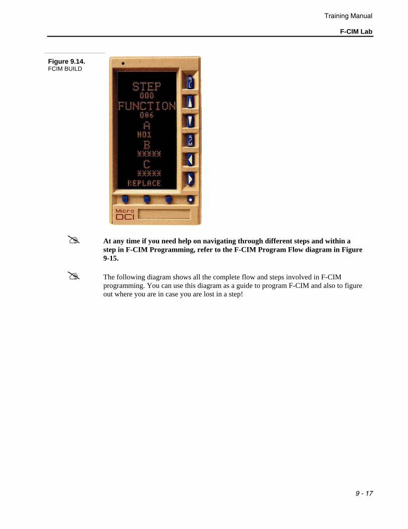
• The default value of B is shown at the bottom now. As per our work sheet (Table
9-3), we do not connect anything for the B and C inputs. Press F3 to save this step. Now you will notice that REPLACE displayed at the bottom as shown in the next figure. Programming of Step 00 is complete now. So we should now proceed to the next step (Step 01).
Training Manual
F-CIM Lab
9 - 17
Figure 9.14. FCIM BUILD
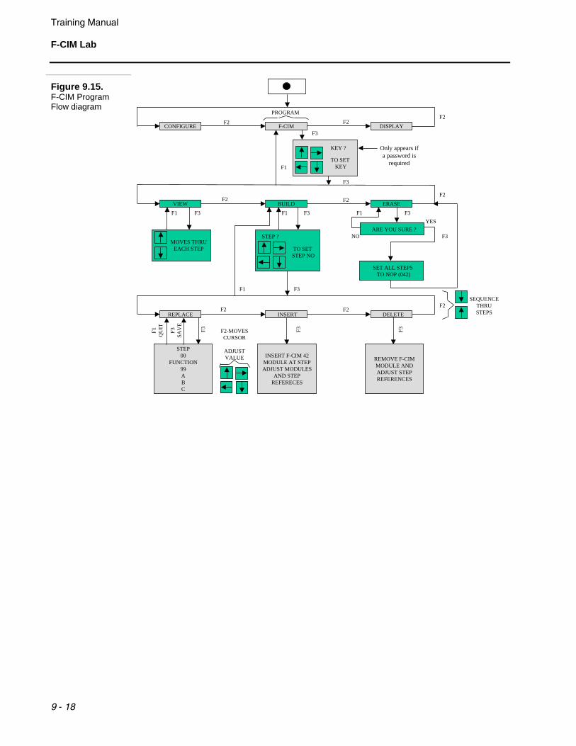
At any time if you need help on navigating through different steps and within a step in F-CIM Programming, refer to the F-CIM Program Flow diagram in Figure 9-15.
The following diagram shows all the complete flow and steps involved in F-CIM programming. You can use this diagram as a guide to program F-CIM and also to figure out where you are in case you are lost in a step!
Training Manual F-CIM Lab
9 - 18
Figure 9.15. F-CIM Program Flow diagram
CONFIGURE F-CIM DISPLAY
VIEW BUILD ERASE
REPLACE INSERT DELETE
STEP00
FUNCTION99ABC
INSERT F-CIM 42MODULE AT STEPADJUST MODULES
AND STEPREFERECES
REMOVE F-CIMMODULE ANDADJUST STEPREFERENCES
F3SA
VE
F1Q
UIT F3 F3
MOVES THRUEACH STEP TO SET
STEP NO
STEP ?ARE YOU SURE ?
SET ALL STEPS TO NOP (042)
TO SET KEY
KEY ?
F2SEQUENCE
THRU STEPS
PROGRAM
F2 F2F2
F2 F2F2
F2 F2
F3
F3F1
F3
F3F1YES
NO
F1 F3F3F1
F3
F3
F1
Only appears ifa password is
required
F2-MOVESCURSOR
ADJUSTVALUE
Training Manual
F-CIM Lab
9 - 19
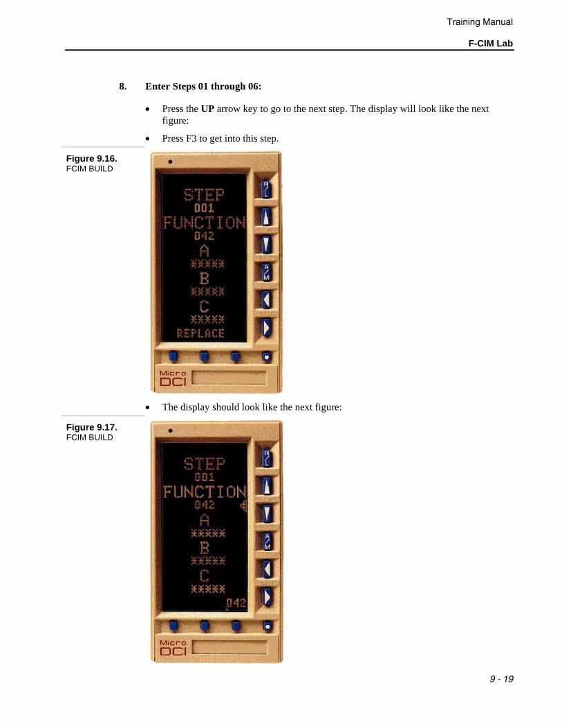
8. Enter Steps 01 through 06:
• Press the UP arrow key to go to the next step. The display will look like the next figure:
• Press F3 to get into this step.
Figure 9.16. FCIM BUILD
• The display should look like the next figure:
Figure 9.17. FCIM BUILD
Training Manual F-CIM Lab
9 - 20
• Program Step 01 from here. Refer to the Worksheet in Table 9-3 for the function code and inputs A, B and C. Follow the same procedure as the previous step except for the values to be entered.
• If no changes are to be made to a particular data position, press the F2 key to cycle to the next data position. Refer to the F-CIM Program Flow diagram in Figure 9-15 for help.
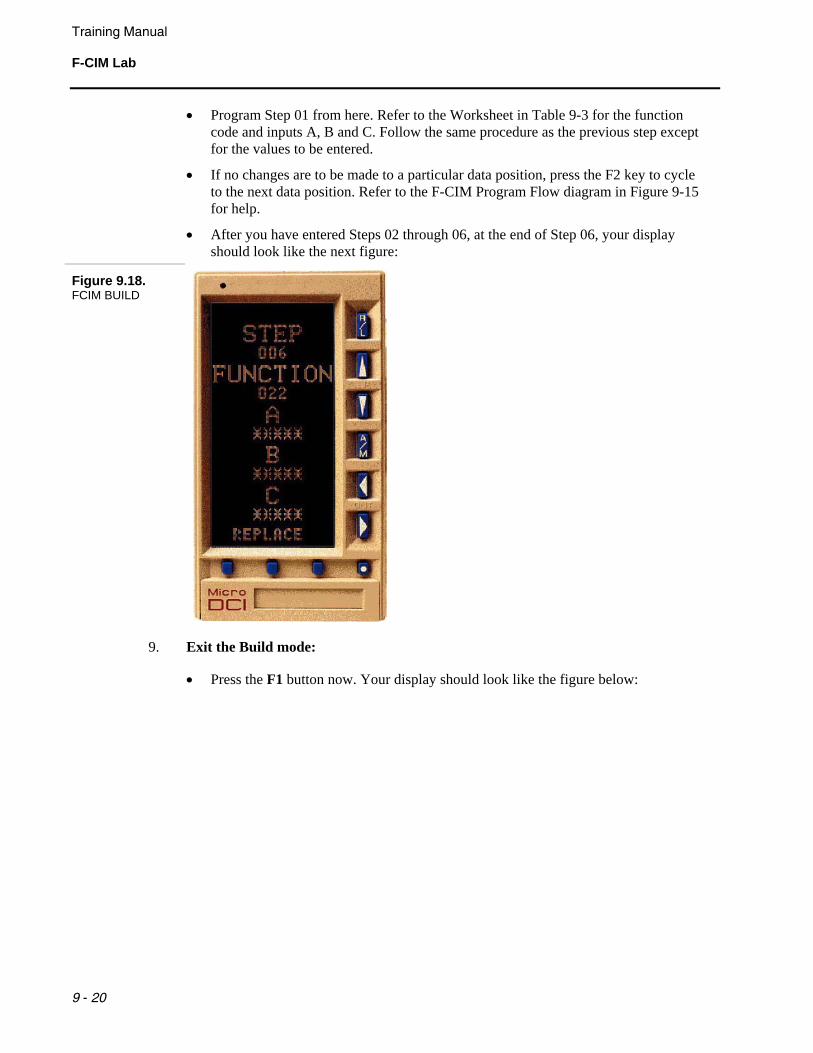
• After you have entered Steps 02 through 06, at the end of Step 06, your display should look like the next figure:
Figure 9.18. FCIM BUILD
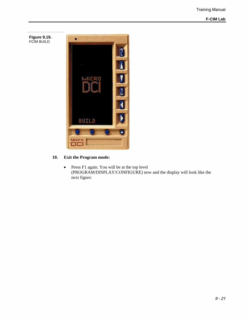
9. Exit the Build mode:
• Press the F1 button now. Your display should look like the figure below:
Training Manual
F-CIM Lab
9 - 21
Figure 9.19. FCIM BUILD
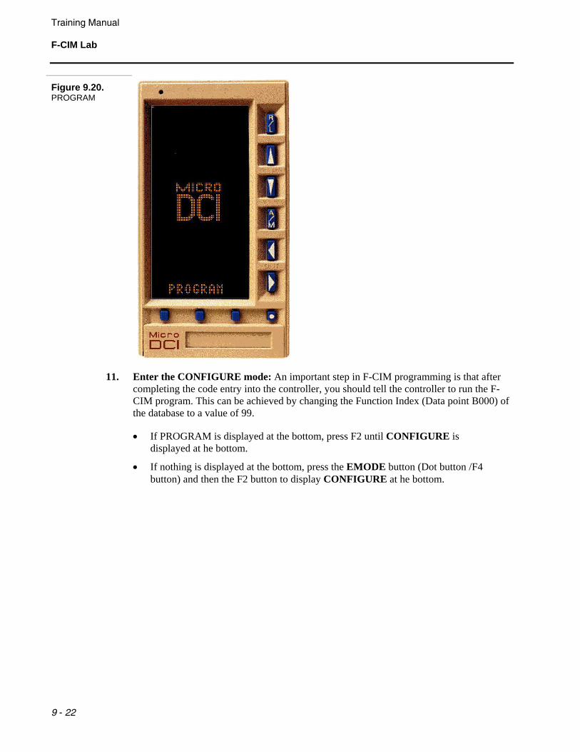
10. Exit the Program mode:
• Press F1 again. You will be at the top level (PROGRAM/DISPLAY/CONFIGURE) now and the display will look like the next figure:
Training Manual F-CIM Lab
9 - 22
Figure 9.20. PROGRAM
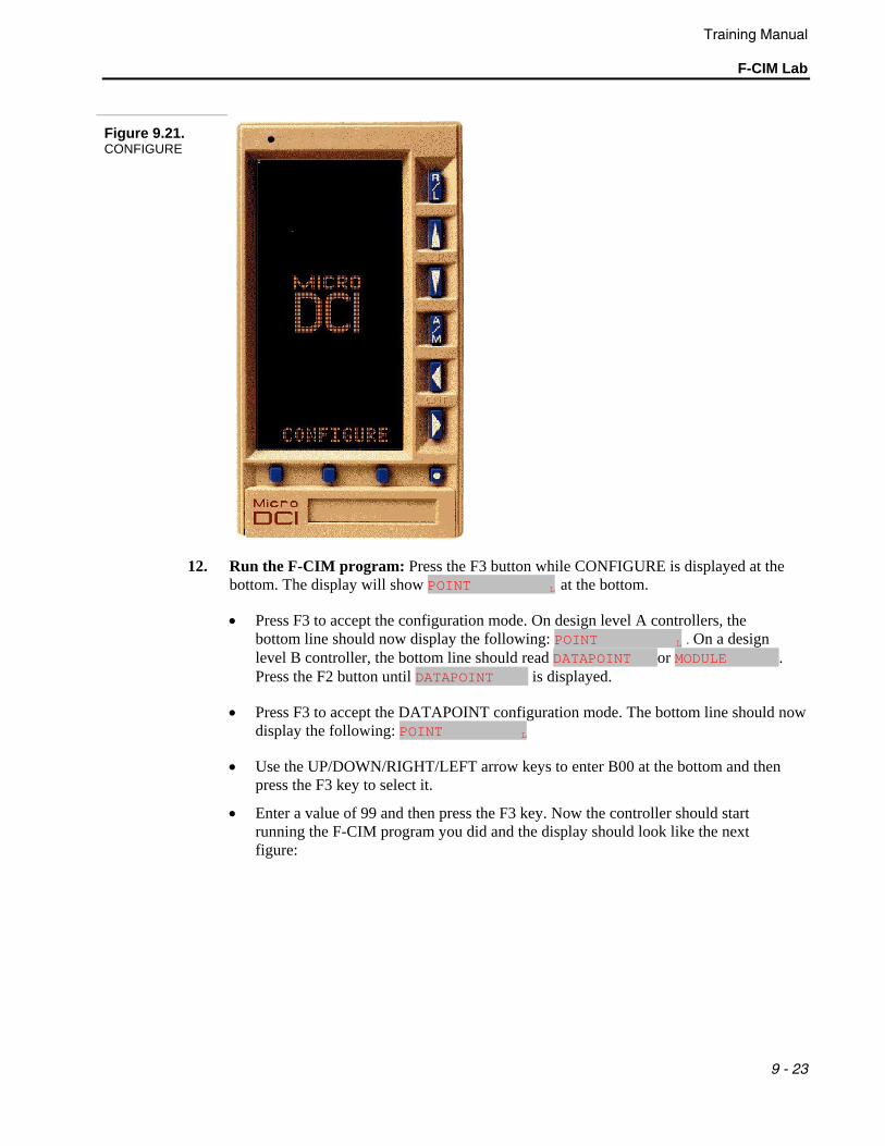
11. Enter the CONFIGURE mode: An important step in F-CIM programming is that after completing the code entry into the controller, you should tell the controller to run the F-CIM program. This can be achieved by changing the Function Index (Data point B000) of the database to a value of 99.
• If PROGRAM is displayed at the bottom, press F2 until CONFIGURE is displayed at he bottom.
• If nothing is displayed at the bottom, press the EMODE button (Dot button /F4 button) and then the F2 button to display CONFIGURE at he bottom.
Training Manual
F-CIM Lab
9 - 23
Figure 9.21. CONFIGURE
12. Run the F-CIM program: Press the F3 button while CONFIGURE is displayed at the bottom. The display will show POINT L at the bottom.
• Press F3 to accept the configuration mode. On design level A controllers, the bottom line should now display the following: POINT L . On a design level B controller, the bottom line should read DATAPOINT or MODULE . Press the F2 button until DATAPOINT 5 is displayed.
• Press F3 to accept the DATAPOINT configuration mode. The bottom line should now display the following: POINT L
• Use the UP/DOWN/RIGHT/LEFT arrow keys to enter B00 at the bottom and then press the F3 key to select it.
• Enter a value of 99 and then press the F3 key. Now the controller should start running the F-CIM program you did and the display should look like the next figure:
Training Manual F-CIM Lab
9 - 24
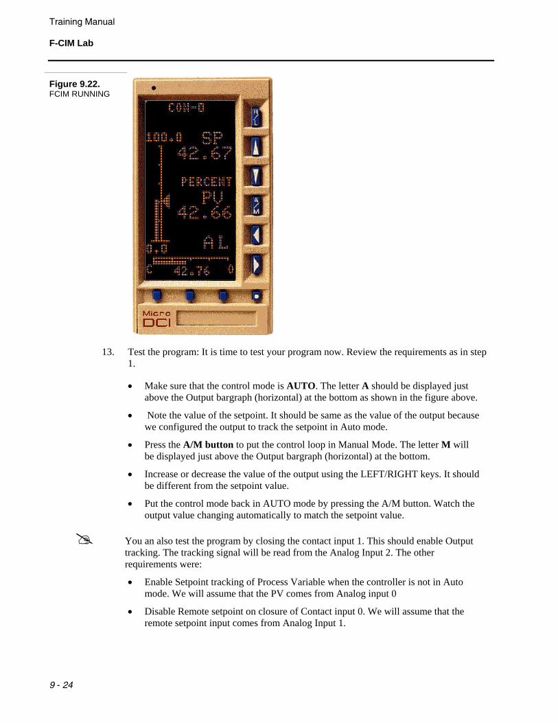
Figure 9.22. FCIM RUNNING
13. Test the program: It is time to test your program now. Review the requirements as in step 1.
• Make sure that the control mode is AUTO. The letter A should be displayed just above the Output bargraph (horizontal) at the bottom as shown in the figure above.
• Note the value of the setpoint. It should be same as the value of the output because we configured the output to track the setpoint in Auto mode.
• Press the A/M button to put the control loop in Manual Mode. The letter M will be displayed just above the Output bargraph (horizontal) at the bottom.
• Increase or decrease the value of the output using the LEFT/RIGHT keys. It should be different from the setpoint value.
• Put the control mode back in AUTO mode by pressing the A/M button. Watch the output value changing automatically to match the setpoint value.
You an also test the program by closing the contact input 1. This should enable Output tracking. The tracking signal will be read from the Analog Input 2. The other requirements were:
• Enable Setpoint tracking of Process Variable when the controller is not in Auto mode. We will assume that the PV comes from Analog input 0
• Disable Remote setpoint on closure of Contact input 0. We will assume that the remote setpoint input comes from Analog Input 1.

Training Manual
F-CIM Lab
9 - 25
9.4.2 Part 2 - F-CIM Programming from Micro-Tools In Part 1, we learnt how to program F-CIM from the front keypad. In this Part, we will learn how to program F-CIM from Micro-Tools. We will use the same control strategy and the same worksheet (Table 9-3) for doing this F-CIM program using Micro-Tools.
1. Create a new F-CIM program:
• Select the Project Manager in Micro-Tools. From the Project Manager, select the Project folder and then the controller that we will create the FCIM strategy for.
• When the controller tag name is highlighted, the right side window will list the functions that can be performed for this controller (refer to figure below).
Figure 9.23. Project Explorer
• The third item in the list is the FCIM. Right mouse click on the editor and select
edit from the pull-down menu.
• Two new windows will appear on the screen, one large window work area and second smaller window containing a function block selection list. See the next figure
Training Manual F-CIM Lab
9 - 26
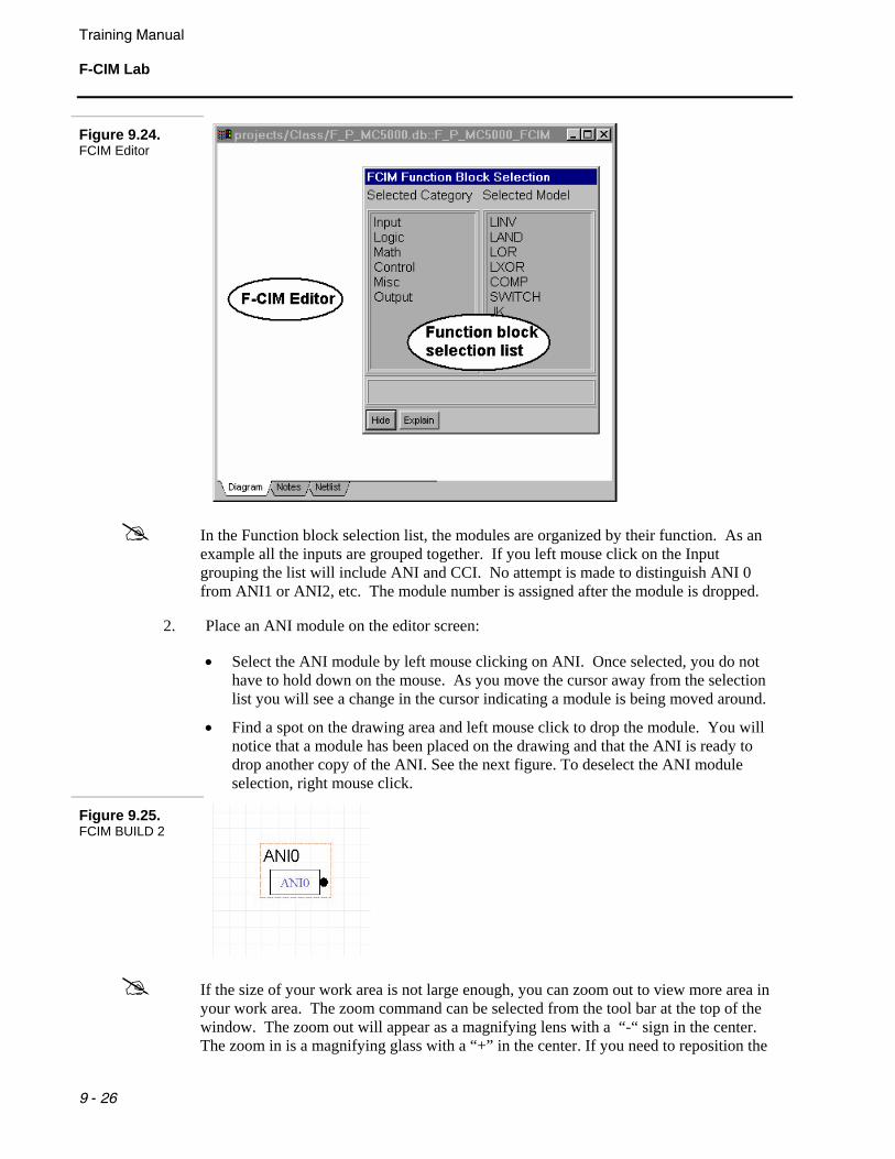
Figure 9.24. FCIM Editor
In the Function block selection list, the modules are organized by their function. As an example all the inputs are grouped together. If you left mouse click on the Input grouping the list will include ANI and CCI. No attempt is made to distinguish ANI 0 from ANI1 or ANI2, etc. The module number is assigned after the module is dropped.
2. Place an ANI module on the editor screen:
• Select the ANI module by left mouse clicking on ANI. Once selected, you do not have to hold down on the mouse. As you move the cursor away from the selection list you will see a change in the cursor indicating a module is being moved around.
• Find a spot on the drawing area and left mouse click to drop the module. You will notice that a module has been placed on the drawing and that the ANI is ready to drop another copy of the ANI. See the next figure. To deselect the ANI module selection, right mouse click.
Figure 9.25. FCIM BUILD 2
If the size of your work area is not large enough, you can zoom out to view more area in your work area. The zoom command can be selected from the tool bar at the top of the window. The zoom out will appear as a magnifying lens with a “-“ sign in the center. The zoom in is a magnifying glass with a “+” in the center. If you need to reposition the
Training Manual
F-CIM Lab
9 - 27
module on the worksheet, left mouse click on the module. The module will be outlined in red when selected. If you left mouse click on the module and hold the button down you can drag the module to its new position.
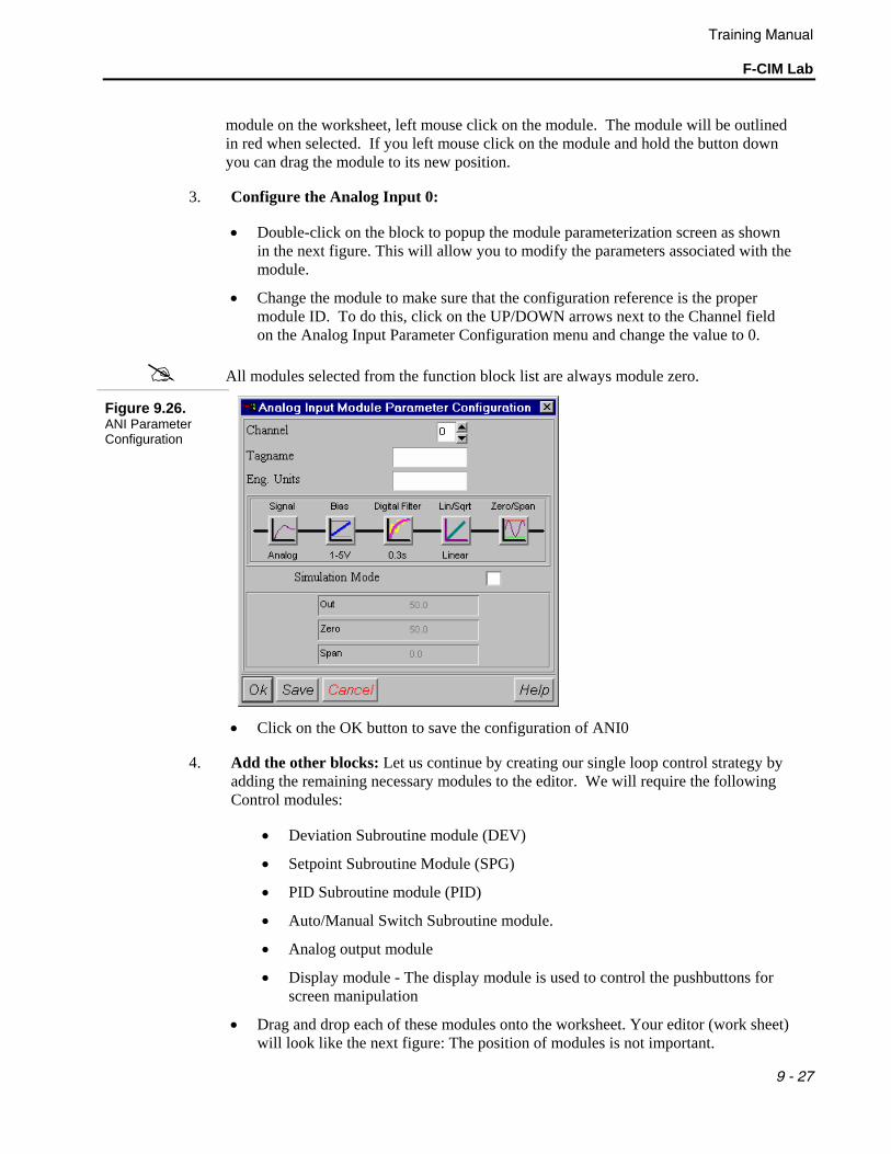
3. Configure the Analog Input 0:
• Double-click on the block to popup the module parameterization screen as shown in the next figure. This will allow you to modify the parameters associated with the module.
• Change the module to make sure that the configuration reference is the proper module ID. To do this, click on the UP/DOWN arrows next to the Channel field on the Analog Input Parameter Configuration menu and change the value to 0.
All modules selected from the function block list are always module zero.
Figure 9.26. ANI Parameter Configuration
• Click on the OK button to save the configuration of ANI0
4. Add the other blocks: Let us continue by creating our single loop control strategy by adding the remaining necessary modules to the editor. We will require the following Control modules:
• Deviation Subroutine module (DEV)
• Setpoint Subroutine Module (SPG)
• PID Subroutine module (PID)
• Auto/Manual Switch Subroutine module.
• Analog output module
• Display module - The display module is used to control the pushbuttons for screen manipulation
• Drag and drop each of these modules onto the worksheet. Your editor (work sheet) will look like the next figure: The position of modules is not important.
Training Manual F-CIM Lab
9 - 28
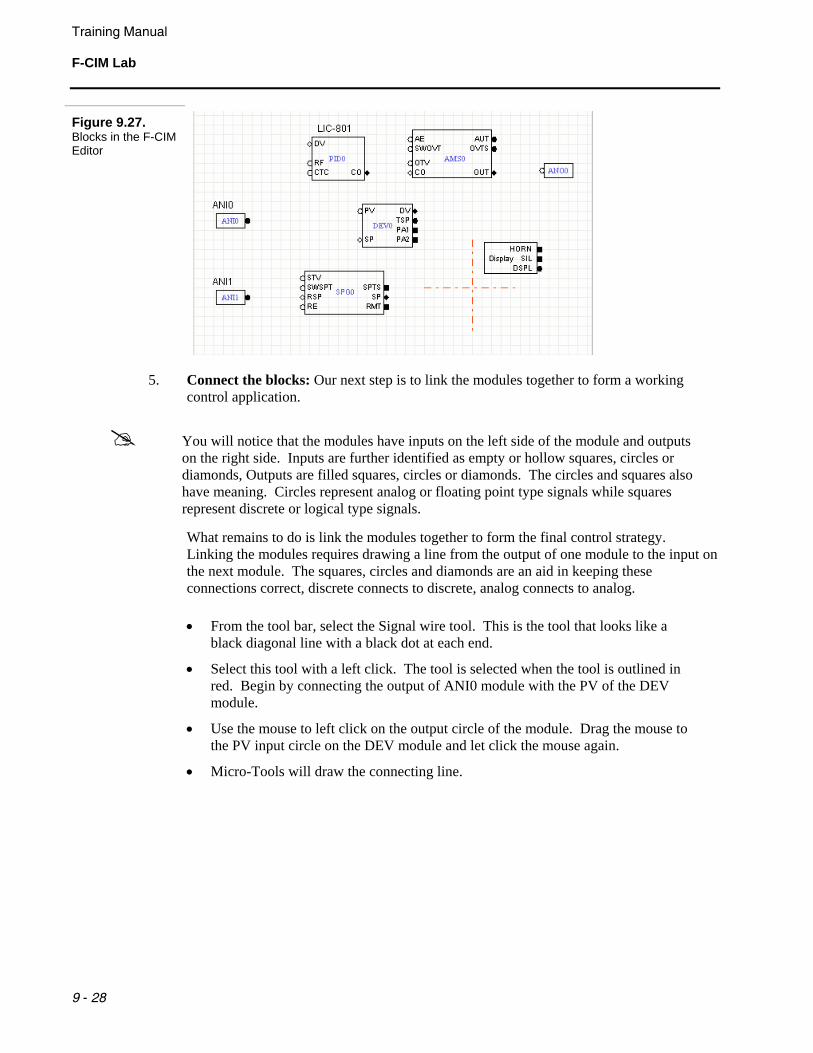
Figure 9.27. Blocks in the F-CIM Editor
5. Connect the blocks: Our next step is to link the modules together to form a working control application.
You will notice that the modules have inputs on the left side of the module and outputs on the right side. Inputs are further identified as empty or hollow squares, circles or diamonds, Outputs are filled squares, circles or diamonds. The circles and squares also have meaning. Circles represent analog or floating point type signals while squares represent discrete or logical type signals.
What remains to do is link the modules together to form the final control strategy. Linking the modules requires drawing a line from the output of one module to the input on the next module. The squares, circles and diamonds are an aid in keeping these connections correct, discrete connects to discrete, analog connects to analog.
• From the tool bar, select the Signal wire tool. This is the tool that looks like a black diagonal line with a black dot at each end.
• Select this tool with a left click. The tool is selected when the tool is outlined in red. Begin by connecting the output of ANI0 module with the PV of the DEV module.
• Use the mouse to left click on the output circle of the module. Drag the mouse to the PV input circle on the DEV module and let click the mouse again.
• Micro-Tools will draw the connecting line.
Training Manual
F-CIM Lab
9 - 29
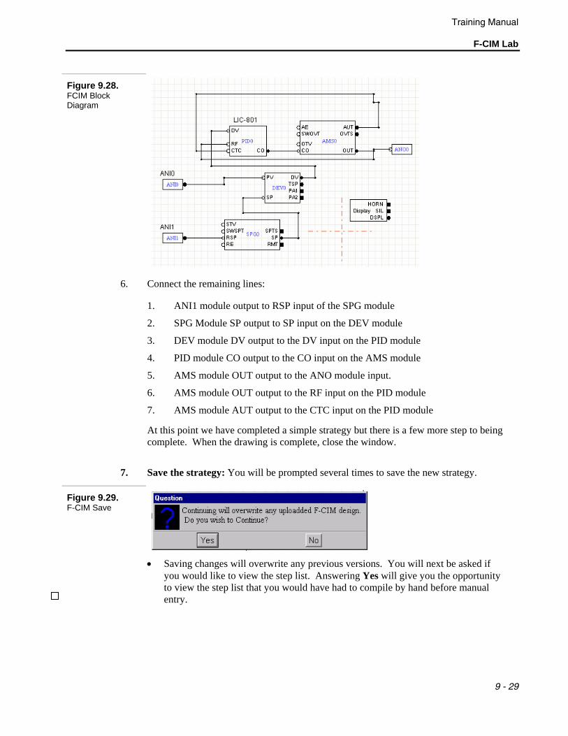
Figure 9.28. FCIM Block Diagram
6. Connect the remaining lines:
1. ANI1 module output to RSP input of the SPG module
2. SPG Module SP output to SP input on the DEV module
3. DEV module DV output to the DV input on the PID module
4. PID module CO output to the CO input on the AMS module
5. AMS module OUT output to the ANO module input.
6. AMS module OUT output to the RF input on the PID module
7. AMS module AUT output to the CTC input on the PID module
At this point we have completed a simple strategy but there is a few more step to being complete. When the drawing is complete, close the window.
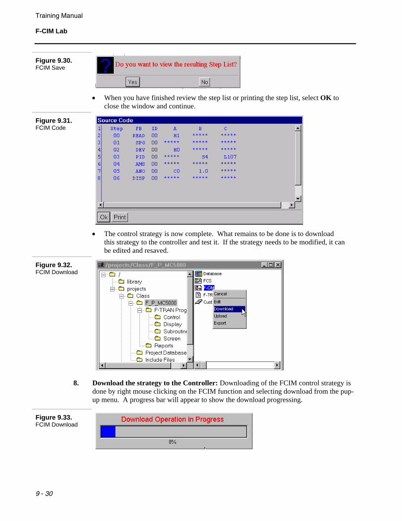
7. Save the strategy: You will be prompted several times to save the new strategy.
Figure 9.29. F-CIM Save
• Saving changes will overwrite any previous versions. You will next be asked if
you would like to view the step list. Answering Yes will give you the opportunity to view the step list that you would have had to compile by hand before manual entry.
Training Manual F-CIM Lab
9 - 30
Figure 9.30. FCIM Save
• When you have finished review the step list or printing the step list, select OK to
close the window and continue.
Figure 9.31. FCIM Code
• The control strategy is now complete. What remains to be done is to download
this strategy to the controller and test it. If the strategy needs to be modified, it can be edited and resaved.
Figure 9.32. FCIM Download
8. Download the strategy to the Controller: Downloading of the FCIM control strategy is done by right mouse clicking on the FCIM function and selecting download from the pup-up menu. A progress bar will appear to show the download progressing.
Figure 9.33. FCIM Download
Training Manual
F-CIM Lab
9 - 31
• When the down load is complete, a Down Load Successful message will appear. Click OK to clear the message. When the down load begins, the controller is placed into suspend mode and the ABB logo will be displayed.
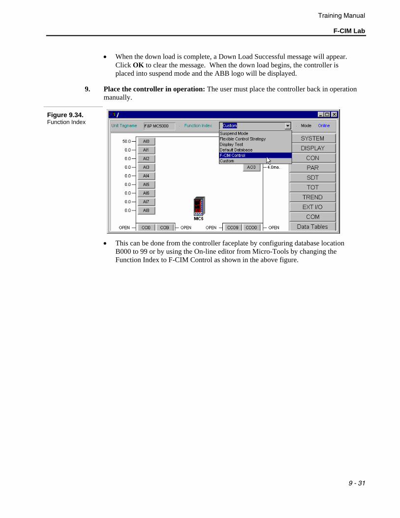
9. Place the controller in operation: The user must place the controller back in operation manually.
Figure 9.34. Function Index
• This can be done from the controller faceplate by configuring database location
B000 to 99 or by using the On-line editor from Micro-Tools by changing the Function Index to F-CIM Control as shown in the above figure.

Training Manual F-CIM Lab
9 - 32
Notes:

![ETSI ISG CIM · [JSON-LD] 20170608 Introduction to ISG CIM CIM-002-UC CIM -003 GAP CIM-004-APIprelim CIM-005-DPP CIM-001-AB ) CIM-006-MOD0. Timeline in ToR 02/2017 First General Meeting](https://cdn.vdocuments.mx/doc/165x107/6002860fd1e0f63f360db5f2/etsi-isg-cim-json-ld-20170608-introduction-to-isg-cim-cim-002-uc-cim-003-gap.jpg)


