Temporary Structures
Shotcrete
Professor Kamran M. Nemati
Spring Quarter 2018 1
Temporary Structures
Field Application of
ShotcreteAn overview of field shotcrete operations
Temporary Structures
2
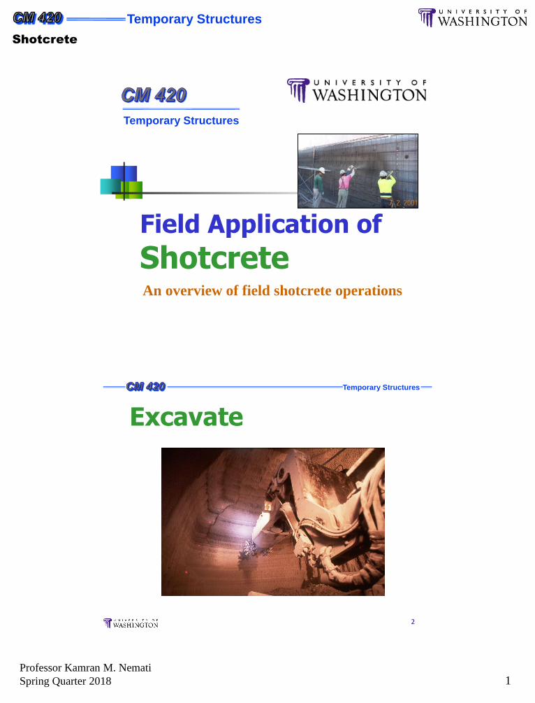
Excavate
Temporary Structures
Shotcrete
Professor Kamran M. Nemati
Spring Quarter 2018 2
Temporary Structures
3
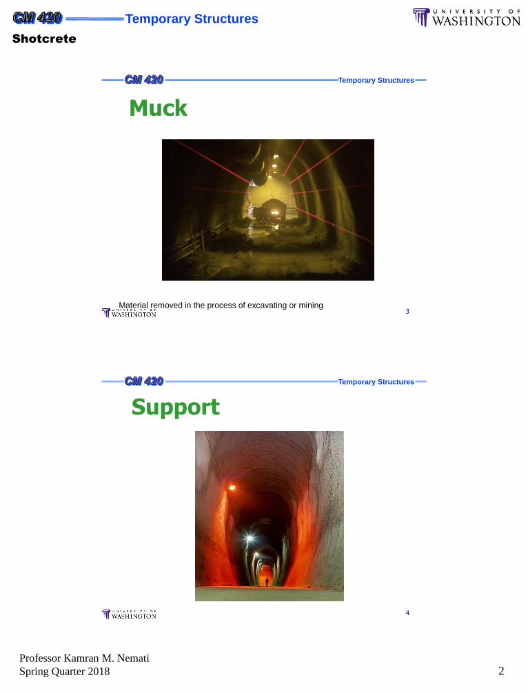
Muck
Material removed in the process of excavating or mining
Temporary Structures
4
Support
Temporary Structures
Shotcrete
Professor Kamran M. Nemati
Spring Quarter 2018 3
Temporary Structures
5
The shotcrete process has grown into an important and widely used construction technique.
In 1910, a double chambered cement gun was introduced to the construction industry.
The sand-cement product of this device was given the proprietary name Gunite.
In the ensuing years, trade marks such as Guncrete, pneucrete, Blastcrete, Blocrete, Jetcrete, and the terms pneumatically applied mortar and concrete, were introduced to describe similar processes.
Introduction and History
Temporary Structures
6
The early 1930s saw the generic term “shotcrete” introduced by the American Railway Engineering Association to describe the Gunite process.
In 1951, the American Concrete Institute (ACI) adopted the term shotcrete to describe the dry-mix process.
Shotcrete is now applied to the wet-mix process and has gained universal acceptance in the United States.
Introduction and History
Temporary Structures
Shotcrete
Professor Kamran M. Nemati
Spring Quarter 2018 4
Temporary Structures
7
Gunite / Mortar: Maximum aggregate size = sand
Shotcrete : Maximum aggregate size = 3/8” typical (1/2” max)
AKA: Sprayed Concrete (Europe)
Relevant ACI Publications
506R-90 Guide to Shotcrete
506.3R-91 Guide to Certification of Shotcrete Nozzlemen
506.4R-94 Guide for the Evaluation of Shotcrete
506.2-95 Specification for Materials, Proportioning and Application of Shotcrete
506.1R-98 State of the Art Report on Fiber Reinforced Shotcrete
Definition Of Terms /References
Temporary Structures
8
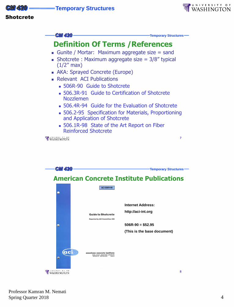
Internet Address:
http://aci-int.org
506R-90 = $52.95
(This is the base document)
American Concrete Institute Publications
Temporary Structures
Shotcrete
Professor Kamran M. Nemati
Spring Quarter 2018 5
Temporary Structures
9
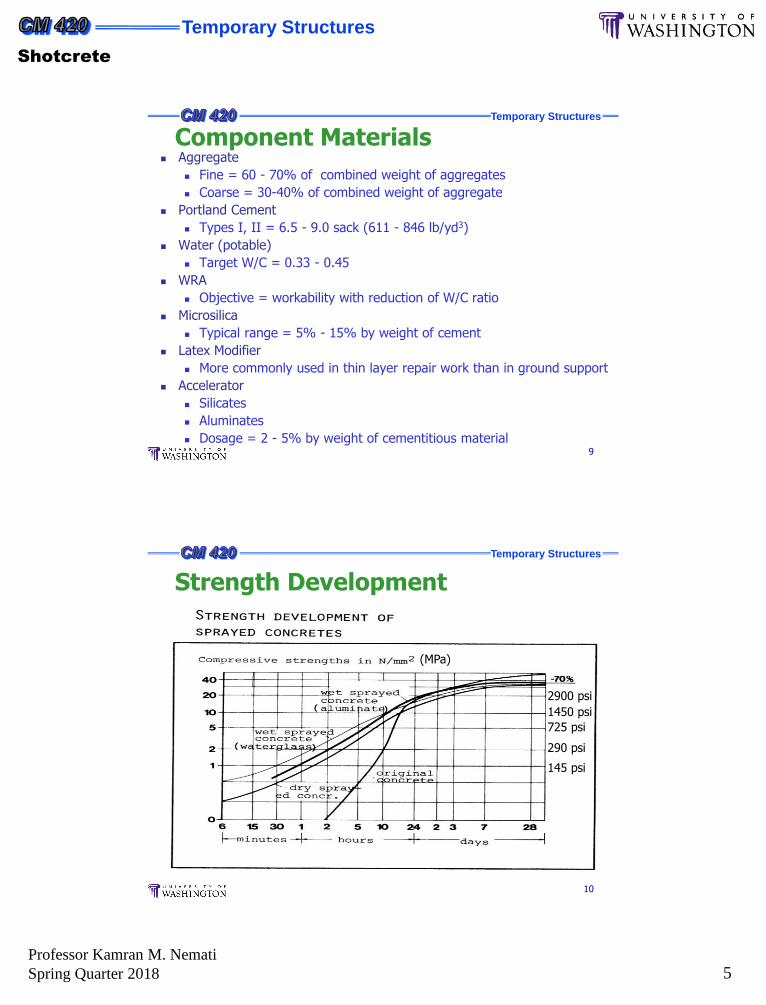
Aggregate
Fine = 60 - 70% of combined weight of aggregates
Coarse = 30-40% of combined weight of aggregate
Portland Cement
Types I, II = 6.5 - 9.0 sack (611 - 846 lb/yd3)
Water (potable)
Target W/C = 0.33 - 0.45
WRA
Objective = workability with reduction of W/C ratio
Microsilica
Typical range = 5% - 15% by weight of cement
Latex Modifier
More commonly used in thin layer repair work than in ground support
Accelerator
Silicates
Aluminates
Dosage = 2 - 5% by weight of cementitious material
Component Materials
Temporary Structures
10
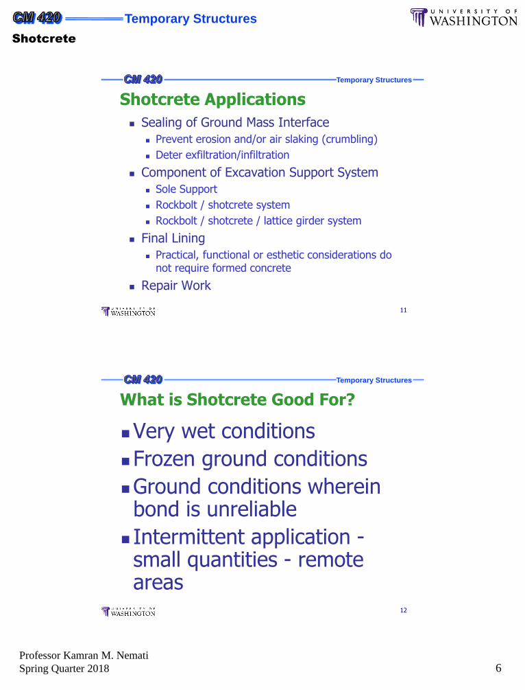
2900 psi
1450 psi
Strength Development
145 psi
725 psi
290 psi
(MPa)
Temporary Structures
Shotcrete
Professor Kamran M. Nemati
Spring Quarter 2018 6
Temporary Structures
11
Sealing of Ground Mass Interface
Prevent erosion and/or air slaking (crumbling)
Deter exfiltration/infiltration
Component of Excavation Support System
Sole Support
Rockbolt / shotcrete system
Rockbolt / shotcrete / lattice girder system
Final Lining
Practical, functional or esthetic considerations do not require formed concrete
Repair Work
Shotcrete Applications
Temporary Structures
12
Very wet conditions
Frozen ground conditions
Ground conditions wherein bond is unreliable
Intermittent application -small quantities - remote areas
What is Shotcrete Good For?
Temporary Structures
Shotcrete
Professor Kamran M. Nemati
Spring Quarter 2018 7
Temporary Structures
13
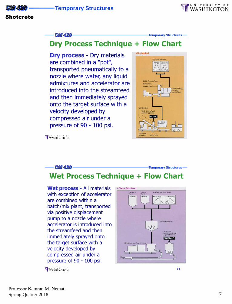
Dry process - Dry materials are combined in a "pot", transported pneumatically to a nozzle where water, any liquid admixtures and accelerator are introduced into the streamfeed and then immediately sprayed onto the target surface with a velocity developed by compressed air under a pressure of 90 - 100 psi.
Dry Process Technique + Flow Chart
Temporary Structures
14
Wet process - All materials with exception of accelerator are combined within a batch/mix plant, transported via positive displacement pump to a nozzle where accelerator is introduced into the streamfeed and then immediately sprayed onto the target surface with a velocity developed by compressed air under a pressure of 90 - 100 psi.
Wet Process Technique + Flow Chart
Temporary Structures
Shotcrete
Professor Kamran M. Nemati
Spring Quarter 2018 8
Temporary Structures
15
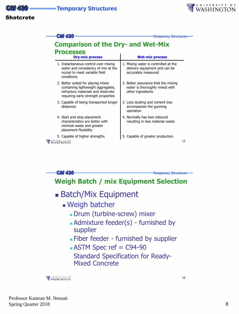
Dry-mix process Wet-mix process
1. Instantaneous control over mixingwater and consistency of mix at thenozzel to meet variable fieldconditions.
1. Mixing water is controlled at thedelivery equipment and can beaccurately measured
2. Better suited for placing mixescontaining lightweight aggregates,refractory materials and shotcreterequiring early strength properties
2. Better assurance that the mixingwater is thoroughly mixed withother ingredients
3. Capable of being transported longerdistances
3. Less dusting and cement lossaccompanies the gunningoperation
4. Start and stop placementcharacteristics are better withminimal waste and greaterplacement flexibility
4. Normally has less reboundresulting in less material waste
5. Capable of higher strengths 5. Capable of greater production
Comparison of the Dry- and Wet-Mix Processes
Temporary Structures
16
Batch/Mix Equipment Weigh batcher
Drum (turbine-screw) mixer
Admixture feeder(s) - furnished by supplier
Fiber feeder - furnished by supplier
ASTM Spec ref = C94-90
Standard Specification for Ready-Mixed Concrete
Weigh Batch / mix Equipment Selection
Temporary Structures
Shotcrete
Professor Kamran M. Nemati
Spring Quarter 2018 9
Temporary Structures
17
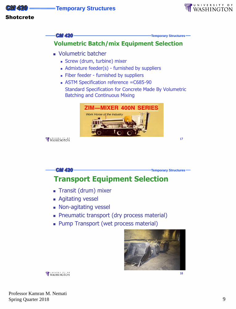
Volumetric batcher
Screw (drum, turbine) mixer
Admixture feeder(s) - furnished by suppliers
Fiber feeder - furnished by suppliers
ASTM Specification reference =C685-90
Standard Specification for Concrete Made By Volumetric Batching and Continuous Mixing
Volumetric Batch/mix Equipment Selection
Temporary Structures
18
Transit (drum) mixer
Agitating vessel
Non-agitating vessel
Pneumatic transport (dry process material)
Pump Transport (wet process material)
Transport Equipment Selection
Temporary Structures
Shotcrete
Professor Kamran M. Nemati
Spring Quarter 2018 10
Temporary Structures
19
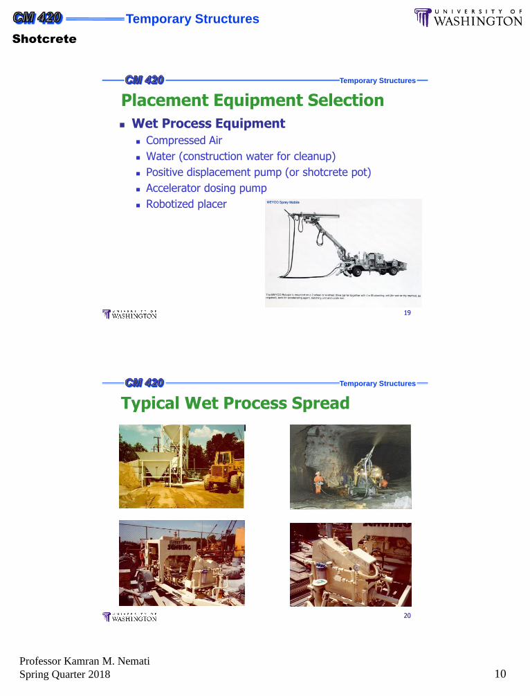
Wet Process Equipment
Compressed Air
Water (construction water for cleanup)
Positive displacement pump (or shotcrete pot)
Accelerator dosing pump
Robotized placer
Placement Equipment Selection
Temporary Structures
20
Typical Wet Process Spread
Temporary Structures
Shotcrete
Professor Kamran M. Nemati
Spring Quarter 2018 11
Temporary Structures
21
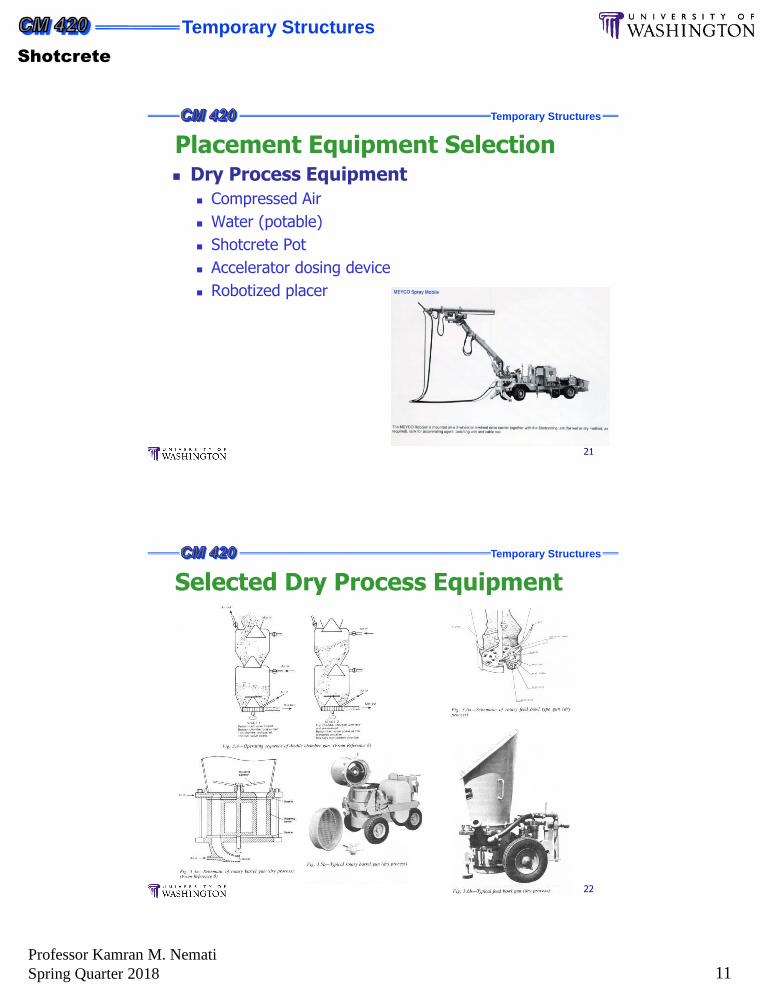
Dry Process Equipment
Compressed Air
Water (potable)
Shotcrete Pot
Accelerator dosing device
Robotized placer
Placement Equipment Selection
Temporary Structures
22
Selected Dry Process Equipment
Temporary Structures
Shotcrete
Professor Kamran M. Nemati
Spring Quarter 2018 12
Temporary Structures
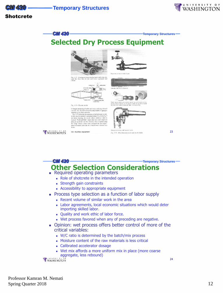
23
Selected Dry Process Equipment
Temporary Structures
24
Required operating parameters Role of shotcrete in the intended operation
Strength gain constraints
Accessibility to appropriate equipment
Process type selection as a function of labor supply Recent volume of similar work in the area
Labor agreements, local economic situations which would deter importing skilled labor.
Quality and work ethic of labor force.
Wet process favored when any of preceding are negative.
Opinion: wet process offers better control of more of the critical variables: W/C ratio is determined by the batch/mix process
Moisture content of the raw materials is less critical
Calibrated accelerator dosage
Wet mix affords a more uniform mix in place (more coarse aggregate, less rebound)
Other Selection Considerations
Temporary Structures
Shotcrete
Professor Kamran M. Nemati
Spring Quarter 2018 13
Temporary Structures
25
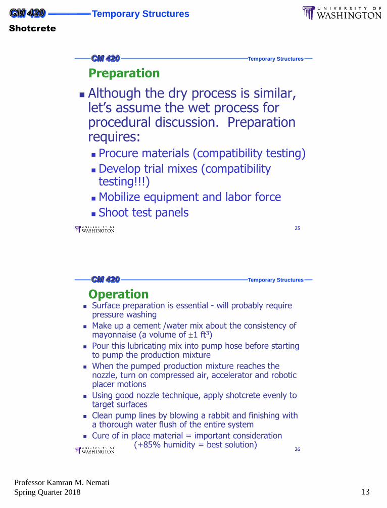
Although the dry process is similar, let’s assume the wet process for procedural discussion. Preparation requires: Procure materials (compatibility testing)
Develop trial mixes (compatibility testing!!!)
Mobilize equipment and labor force
Shoot test panels
Preparation
Temporary Structures
26
Surface preparation is essential - will probably require pressure washing
Make up a cement /water mix about the consistency of mayonnaise (a volume of 1 ft3)
Pour this lubricating mix into pump hose before starting to pump the production mixture
When the pumped production mixture reaches the nozzle, turn on compressed air, accelerator and robotic placer motions
Using good nozzle technique, apply shotcrete evenly to target surfaces
Clean pump lines by blowing a rabbit and finishing with a thorough water flush of the entire system
Cure of in place material = important consideration(+85% humidity = best solution)
Operation
Temporary Structures
Shotcrete
Professor Kamran M. Nemati
Spring Quarter 2018 14
Temporary Structures
27
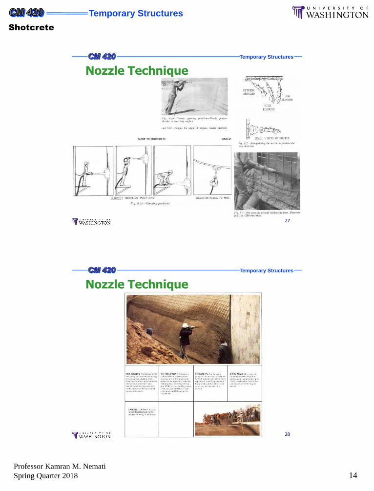
Nozzle Technique
Temporary Structures
28
Nozzle Technique
Temporary Structures
Shotcrete
Professor Kamran M. Nemati
Spring Quarter 2018 15
Temporary Structures
29
Measurement For Payment
Shotcrete by the unit price
Measurement for payment = calculated area (volume)
All plant and process waste
All rebound
All variations in thickness
All variations in plant yield
All materials expended in test phase
Measurement for payment = plant cubic yard
It poses minimal risk
Shotcrete paid as a lump sum
Administrative Nuances of Shotcrete


