Download - Eye Tracker
Copyright © 2004 by the Association for Computing Machinery, Inc.
Permission to make digital or hard copies of part or all of this work for personal or
classroom use is granted without fee provided that copies are not made or distributed
for commercial advantage and that copies bear this notice and the full citation on the
first page. Copyrights for components of this work owned by others than ACM must be
honored. Abstracting with credit is permitted. To copy otherwise, to republish, to post on
servers, or to redistribute to lists, requires prior specific permission and/or a fee.
Request permissions from Permissions Dept, ACM Inc., fax +1 (212) 869-0481 or e-mail
© 2004 ACM 1-58113-825-3/04/0003 $5.00
Building a lightweight eyetracking headgear
Jason S.Babcock & Jeff B. PelzRochester Institute of Technology
Abstract
Eyetracking systems that use video-based cameras to monitor theeye and scene can be made significantly smaller thanks to tinymicro-lens video cameras. Pupil detection algorithms aregenerally implemented in hardware, allowing for real-timeeyetracking. However, it is likely that real-time eyetracking willsoon be fully accomplished in software alone. This paperencourages an “open-source” approach to eyetracking byproviding practical tips on building a lightweight eyetracker fromcommercially available micro-lens cameras and other parts. Whilethe headgear described here can be used with any dark-pupileyetracking controller, it also opens the door to open-sourcesoftware solutions that could be developed by the eyetracking andimage-processing communities. Such systems could be optimizedwithout concern for real-time performance because the systemscould be run offline.
Keywords: lightweight, eyetracking, wearable, headgear
1 Introduction
In the last five years the ability to do eyetracking outside of thelaboratory has expanded the range of experiments that arepossible. Experiments performed in artificial laboratory settingshave shifted towards experiments performed under realisticconditions where observers can move their heads and walk freely.Only recently has the technology been available to study eyemovements that occur under these more natural conditions. Landet al. (1992, 1997, 1999), Pelz et. al. (2000, 2001), Canosa (2000),and Babcock et. al. (2002), have used portable video-basedeyetrackers to monitor subjects’ eye movements as they performover-learned tasks such as tea making, handwashing, and evenhow people compose photographs with digital cameras.
While this research has provided novel insight into observers’visual strategies and behavior, there is also great potential to useeyetracking as a means of interacting with computers and otherdevices. Unfortunately, commercially available eyetrackers can beexpensive, platform specific, and difficult to use. An open-sourcesystem would virtually allow anyone to explore eyetracking inmany new ways. Further, new avenues of interaction forelectronic media will certainly develop as a result of an open-source system. For this to happen it is clear that the nextgeneration of eyetrackers should be more robust, less obtrusive,lightweight, and, most importantly, accessible to a largeraudience.--------------------------------------------
e-mail: [email protected] , [email protected]
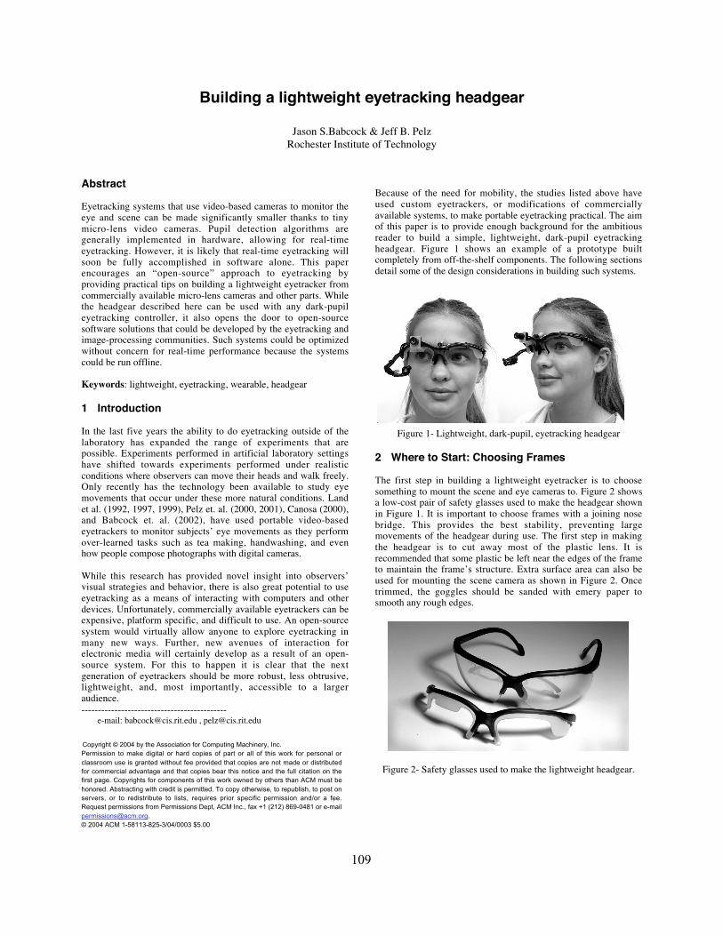
Because of the need for mobility, the studies listed above haveused custom eyetrackers, or modifications of commerciallyavailable systems, to make portable eyetracking practical. The aimof this paper is to provide enough background for the ambitiousreader to build a simple, lightweight, dark-pupil eyetrackingheadgear. Figure 1 shows an example of a prototype builtcompletely from off-the-shelf components. The following sectionsdetail some of the design considerations in building such systems.
Figure 1- Lightweight, dark-pupil, eyetracking headgear
2 Where to Start: Choosing Frames
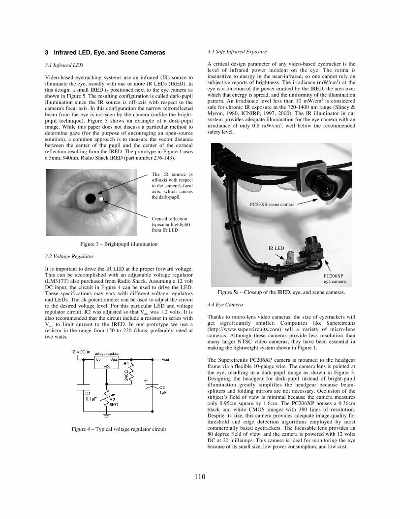
The first step in building a lightweight eyetracker is to choosesomething to mount the scene and eye cameras to. Figure 2 showsa low-cost pair of safety glasses used to make the headgear shownin Figure 1. It is important to choose frames with a joining nosebridge. This provides the best stability, preventing largemovements of the headgear during use. The first step in makingthe headgear is to cut away most of the plastic lens. It isrecommended that some plastic be left near the edges of the frameto maintain the frame’s structure. Extra surface area can also beused for mounting the scene camera as shown in Figure 2. Oncetrimmed, the goggles should be sanded with emery paper tosmooth any rough edges.
Figure 2- Safety glasses used to make the lightweight headgear.
109
3 Infrared LED, Eye, and Scene Cameras
3.1 Infrared LED
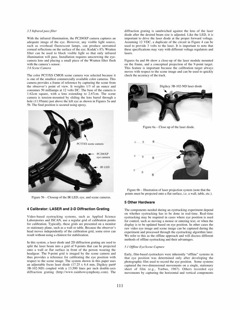
Video-based eyetracking systems use an infrared (IR) source toilluminate the eye, usually with one or more IR LEDs (IRED). Inthis design, a small IRED is positioned next to the eye camera asshown in Figure 5. The resulting configuration is called dark-pupilillumination since the IR source is off-axis with respect to thecamera's focal axis. In this configuration the narrow retroreflectedbeam from the eye is not seen by the camera (unlike the bright-pupil technique). Figure 3 shows an example of a dark-pupilimage. While this paper does not discuss a particular method todetermine gaze (for the purpose of encouraging an open-sourcesolution), a common approach is to measure the vector distancebetween the center of the pupil and the center of the cornealreflection resulting from the IRED. The prototype in Figure 1 usesa 5mm, 940nm, Radio Shack IRED (part number 276-143).
Figure 3 – Brightpupil illumination
3.2 Voltage Regulator
It is important to drive the IR LED at the proper forward voltage.This can be accomplished with an adjustable voltage regulator(LM317T) also purchased from Radio Shack. Assuming a 12 voltDC input, the circuit in Figure 4 can be used to drive the LED.These specifications may vary with different voltage regulatorsand LEDs. The 5k potentiometer can be used to adjust the circuitto the desired voltage level. For this particular LED and voltageregulator circuit, R2 was adjusted so that Vout was 1.2 volts. It isalso recommended that the circuit include a resistor in series withVout to limit current to the IRED. In our prototype we use aresistor in the range from 120 to 220 Ohms, preferably rated attwo watts.
Figure 4 – Typical voltage regulator circuit
3.3 Safe Infrared Exposure
A critical design parameter of any video-based eyetracker is thelevel of infrared power incident on the eye. The retina isinsensitive to energy in the near-infrared, so one cannot rely onsubjective reports of brightness. The irradiance (mW/cm2) at theeye is a function of the power emitted by the IRED, the area overwhich that energy is spread, and the uniformity of the illuminationpattern. An irradiance level less than 10 mW/cm2 is consideredsafe for chronic IR exposure in the 720-1400 nm range (Sliney &Myron, 1980, ICNIRP, 1997, 2000). The IR illuminator in oursystem provides adequate illumination for the eye camera with anirradiance of only 0.8 mW/cm2, well below the recommendedsafety level.
Figure 5a – Closeup of the IRED, eye, and scene cameras.
3.4 Eye Camera
Thanks to micro-lens video cameras, the size of eyetrackers willget significantly smaller. Companies like Supercircuits(http://www.supercircuits.com) sell a variety of micro-lenscameras. Although these cameras provide less resolution thanmany larger NTSC video cameras, they have been essential inmaking the lightweight system shown in Figure 1.
The Supercircuits PC206XP camera is mounted to the headgearframe via a flexible 10-gauge wire. The camera lens is pointed atthe eye, resulting in a dark-pupil image as shown in Figure 3.Designing the headgear for dark-pupil instead of bright-pupilillumination greatly simplifies the headgear because beam-splitters and folding mirrors are not necessary. Occlusion of thesubject’s field of view is minimal because the camera measuresonly 0.95cm square by 1.6cm. The PC206XP houses a 0.36cmblack and white CMOS imager with 380 lines of resolution.Despite its size, this camera provides adequate image-quality forthreshold and edge detection algorithms employed by mostcommercially based eyetrackers. The focusable lens provides an80 degree field of view, and the camera is powered with 12 voltsDC at 20 milliamps. This camera is ideal for monitoring the eyebecause of its small size, low power consumption, and low cost.
Corneal reflection
(specular highlight)
from IR LED
The IR source is
off-axis with respect
to the camera's focal
axis, which causes
the dark-pupil.
PC53XS scene camera
PC206XPeye camera
IR LED
110
3.5 Infrared pass filter
With the infrared illumination, the PC206XP camera captures anadequate image of the eye. However, any visible light source,such as overhead fluorescent lamps, can produce unwantedcorneal reflections on the surface of the eye. Kodak’s 87c Wrattenfilter can be used to block visible light so that only infraredillumination will pass. Installation requires unscrewing the eye-camera lens and placing a small piece of the Wratten filter flushwith the camera’s sensor.3.6 Scene Camera
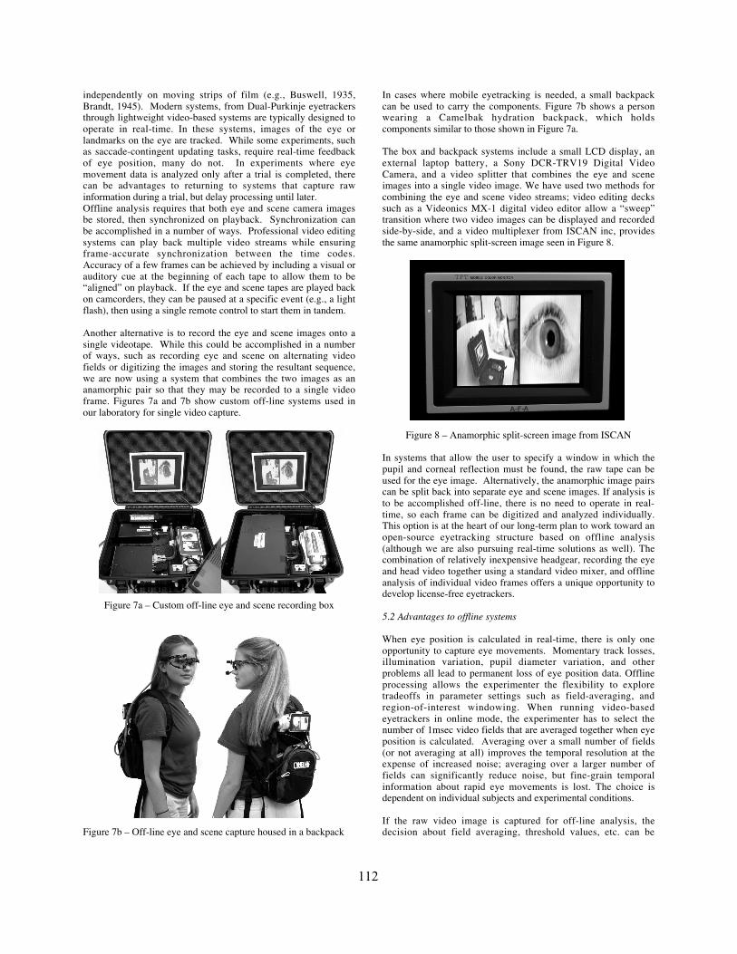
The color PC53XS CMOS scene camera was selected because itis one of the smallest commercially available color cameras. Thiscamera provides a frame of reference by capturing the scene fromthe observer’s point of view. It weights 1/3 of an ounce andconsumes 50 milliamps at 12 volts DC. The base of the camera is1.62cm square, with a lens extending to 2.67cm. The scenecamera is tension-mounted by sliding the lens barrel through ahole (11.95mm) just above the left eye as shown in Figures 5a and5b. The final position is secured using epoxy.
Figure 5b – Closeup of the IR LED, eye, and scene cameras.
4 Calibrator: LASER and 2-D Diffraction Grating
Video-based eyetracking systems, such as Applied ScienceLaboratories and ISCAN, use a regular grid of calibration pointsfor calibration. Typically, these grids are presented on a monitoror stationary plane, such as a wall or table. Because the observer’shead moves independently of the calibration grid, some error canresult without using a chinrest for stabilization.
In this system, a laser diode and 2D diffraction grating are used tosplit the laser beam into a grid of 9-points that can be projectedonto a wall or flat surface in front of the person wearing theheadgear. The 9-point grid is imaged by the scene camera andthus provides a reference for calibrating the eye position withrespect to the scene image. The system shown in this paper usesan adjustable focus laser diode (17.25 x 6.4 mm, Digikey part#3B-102-ND) coupled with a 13,500 lines per inch double-axisdiffraction grating (http://www.rainbowsymphony.com). The
diffraction grating is sandwiched against the lens of the laserdiode after the desired beam size is adjusted. Like the LED, it isimportant to drive the laser diode at the proper forward voltage.Assuming 12 VDC, a duplicate of the circuit in Figure 4 can beused to provide 3 volts to the laser. It is important to note thatthese specifications may vary with different voltage regulators andlasers.
Figures 6a and 6b show a close-up of the laser module mountedon the frame, and a conceptual projection of the 9-point target.This feature is important because the calibration target alwaysmoves with respect to the scene image and can be used to quicklycheck the accuracy of the track.
Figure 6a – Close up of the laser diode.
Figure 6b – Illustration of laser projection system (note that thepoints must be projected onto a flat surface, i.e. a wall, table, etc.).
5 Other Hardware
The components needed during an eyetracking experiment dependon whether eyetracking has to be done in real-time. Real-timeeyetracking may be required in cases where eye position is usedfor control, such as moving a mouse or entering text, or when thedisplay is to be updated based on eye position. In other cases theraw video eye image and scene image can be captured during theexperiment and processed through the eyetracking algorithm later.We refer to this as the offline approach and will discuss differentmethods of offline eyetracking and their advantages.
5.1 Offline Eye/Scene Capture
Early, film-based eyetrackers were inherently “offline” systems inthat eye position was determined only after developing thephotographic film used to record the eye position. Some systemscaptured the two-dimensional movements on a single, stationarysheet of film (e.g., Yarbus, 1967). Others recorded eyemovements by capturing the horizontal and vertical components
PC53XS scene camera
PC206XPeye camera
IR LED
Digikey 3B-102-ND laser diode
111
independently on moving strips of film (e.g., Buswell, 1935,Brandt, 1945). Modern systems, from Dual-Purkinje eyetrackersthrough lightweight video-based systems are typically designed tooperate in real-time. In these systems, images of the eye orlandmarks on the eye are tracked. While some experiments, suchas saccade-contingent updating tasks, require real-time feedbackof eye position, many do not. In experiments where eyemovement data is analyzed only after a trial is completed, therecan be advantages to returning to systems that capture rawinformation during a trial, but delay processing until later.Offline analysis requires that both eye and scene camera imagesbe stored, then synchronized on playback. Synchronization canbe accomplished in a number of ways. Professional video editingsystems can play back multiple video streams while ensuringframe-accurate synchronization between the time codes.Accuracy of a few frames can be achieved by including a visual orauditory cue at the beginning of each tape to allow them to be“aligned” on playback. If the eye and scene tapes are played backon camcorders, they can be paused at a specific event (e.g., a lightflash), then using a single remote control to start them in tandem.
Another alternative is to record the eye and scene images onto asingle videotape. While this could be accomplished in a numberof ways, such as recording eye and scene on alternating videofields or digitizing the images and storing the resultant sequence,we are now using a system that combines the two images as ananamorphic pair so that they may be recorded to a single videoframe. Figures 7a and 7b show custom off-line systems used inour laboratory for single video capture.
Figure 7a – Custom off-line eye and scene recording box
Figure 7b – Off-line eye and scene capture housed in a backpack
In cases where mobile eyetracking is needed, a small backpackcan be used to carry the components. Figure 7b shows a personwearing a Camelbak hydration backpack, which holdscomponents similar to those shown in Figure 7a.
The box and backpack systems include a small LCD display, anexternal laptop battery, a Sony DCR-TRV19 Digital VideoCamera, and a video splitter that combines the eye and sceneimages into a single video image. We have used two methods forcombining the eye and scene video streams; video editing deckssuch as a Videonics MX-1 digital video editor allow a “sweep”transition where two video images can be displayed and recordedside-by-side, and a video multiplexer from ISCAN inc, providesthe same anamorphic split-screen image seen in Figure 8.
Figure 8 – Anamorphic split-screen image from ISCAN
In systems that allow the user to specify a window in which thepupil and corneal reflection must be found, the raw tape can beused for the eye image. Alternatively, the anamorphic image pairscan be split back into separate eye and scene images. If analysis isto be accomplished off-line, there is no need to operate in real-time, so each frame can be digitized and analyzed individually.This option is at the heart of our long-term plan to work toward anopen-source eyetracking structure based on offline analysis(although we are also pursuing real-time solutions as well). Thecombination of relatively inexpensive headgear, recording the eyeand head video together using a standard video mixer, and offlineanalysis of individual video frames offers a unique opportunity todevelop license-free eyetrackers.
5.2 Advantages to offline systems
When eye position is calculated in real-time, there is only oneopportunity to capture eye movements. Momentary track losses,illumination variation, pupil diameter variation, and otherproblems all lead to permanent loss of eye position data. Offlineprocessing allows the experimenter the flexibility to exploretradeoffs in parameter settings such as field-averaging, andregion-of-interest windowing. When running video-basedeyetrackers in online mode, the experimenter has to select thenumber of 1msec video fields that are averaged together when eyeposition is calculated. Averaging over a small number of fields(or not averaging at all) improves the temporal resolution at theexpense of increased noise; averaging over a larger number offields can significantly reduce noise, but fine-grain temporalinformation about rapid eye movements is lost. The choice isdependent on individual subjects and experimental conditions.
If the raw video image is captured for off-line analysis, thedecision about field averaging, threshold values, etc. can be
112
postponed until after the video is collected, when there is moreinformation on which to base the decision. It is also possible torun the video through the eyetracker device several times so onecan test various parameter values.
Off-line analysis can also simplify calibration. Calibrating real-time video eyetrackers typically requires a two-step process inwhich a number of calibration points are first located in the sceneimage, then the subject is instructed to look at the same points.This is often a challenging process that limits calibration accuracybecause any head motion during the entire process will limitaccuracy. The experimenter must also time the instant at which tocapture the image of the eye at each point. A blink or a drift in thesubject’s line of gaze will cause errors in the calibration. Byperforming calibration offline, it is possible to “freeze-frame” theeye and scene video to ensure a stable eye and scene image.Perhaps more importantly, it is possible to locate the calibrationpoints in the scene image and capture raw eye position images onthe same video frame rather than later in the sequence. This cancompletely eliminate errors normally induced by movement of asubject’s head in the time between locating the calibration pointsand the subject fixating on the same points. While the lasercalibrator described in the previous section addresses the problemof maintaining head position during the entire calibration process,offline processing also allows the experimenter to eliminate thepossibility of a blink interfering with the calibration.
6 Conclusion
Researchers doing eyetracking in natural environments haveexpressed the need for custom, easy-to-use eyetrackers. Tinymicro-lens cameras have made it possible to build inexpensive,lightweight headgear that can be used with today’s commercialeyetrackers. This paper has provided some practical tips onputting together a lightweight portable eyetracking headgearmainly to encourage an open-source approach to eyetracking. Wediscuss benefits of utilizing an offline system, which furtheradvocates the license-free idea. As a future step, we alsoencourage the development of open-source eyetracking softwarethat will complement the hardware discussed in this paper.
7 References
BABCOCK, J. S., LIPPS, M., PELZ, J. B. 2002. How people look at picturesbefore, during and after scene capture: Buswell revisited. InB.E.Rogowitz and T. N. Pappas (Eds.), Human Vision and ElectronicImaging V, SPIE Proceedings, 4662, 34-47.
BRANDT, H. F. 1945. How People Look at Pictures, Chicago: Univ.Chicago Press.
B U S W E L L , G. T. 1935. The Psychology of Seeing, New York,Philosophical Library.
CANOSA, R. L. 2000. Eye movements and natural tasks in an extendedenvironment, Master’s Thesis. New York: Rochester Institute ofTechnology.
ICNIRP GUIDELINES. 1997. Guidelines on Limits of Exposure to Broad-Band Incoherent Optical Radiation (0.38 to 3µm). Health Physics Vol.73, 3, 539-554.
ICNIRP GUIDELINES, 2000. Light-Emitting Diodes (LEDS) and LaserDiodes: Implications for Hazard Assessment. Health Physics Vol. 78,6, 744-752.
LAND, M. F. AND FURNEAUX, S. 1997. The knowledge base of theoculomotor system. Phil Trans R Soc Lond, B 352, 1231-1239.
LAND, M. F. , MENNIE, N., RUSTED, J. 1999. The roles of vision and eyemovements in the control of activities of daily living. Perception, 28,1311-1328.
PELZ, J. B., CANOSA, R. L., KUCHARCZYK, D., BABCOCK, J. S., SILVER,A., KONNO, D. 2000. Portable eyetracking: a study of natural eyemovements. In B.E.Rogowitz and T. N. Pappas (Eds.), Human Visionand Electronic Imaging V, SPIE Proceedings, 3659.
PELZ, J. B., CANOSA, R. L., BABCOCK, J. S. 2000. Extended Tasks ElicitComplex Eye Movement Patterns, ETRA 2000: eye tracking researchand applications symposium, 37-43.
PELZ, J. B., CANOSA, R. L. 2001. Oculomotor behavior and perceptualstrategies in complex tasks. Vision Research, 41, 3587-3596.
SLINEY, D., WOLBARST, M. 1980. Safety with Lasers and Other OpticalSources, New York: Plenum Press, p.147.
YARBUS, A. L. 1967. Eye Movements and Vision (B. Haigh , Trans.)Plenum Press, New York.
113
