Configuration-, Parameterization Instruction 45/18-79-EN
Electro-Pneumatic PositionerTZIDC, TZIDC-1x0, TZIDC-2x0
P R O F I
B U S
PROCESS FIELD BUS
®
Blinder Text
2 TZIDC, TZIDC-1x0, TZIDC-2x0 45/18-79-EN
Electro-Pneumatic Positioner
TZIDC, TZIDC-1x0, TZIDC-2x0
Configuration-, Parameterization Instruction 45/18-79-EN
10.2009
Rev. C
Manufacturer: ABB Automation Products GmbH Schillerstraße 72 32425 Minden Germany Tel.: +49 551 905-534 Fax: +49 551 905-555 [email protected] Customer service center Phone: +49 180 5 222 580 Fax: +49 621 381 931-29031 [email protected]
© Copyright 2009 by ABB Automation Products GmbH Subject to changes without notice
This document is protected by copyright. It assists the user in safe and efficient operation of the device. The contents of this document, whether whole or in part, may not be copied or reproduced without prior approval by the copyright holder.
Contents
Contents
45/18-79-EN TZIDC, TZIDC-1x0, TZIDC-2x0 3
1 Safety....................................................................................................................................................................7
1.1 General information and notes for the reader ................................................................................................7 1.2 Intended use...................................................................................................................................................7 1.3 Plates and symbols ........................................................................................................................................8
1.3.1 Safety-/ warning symbols, note symbols.................................................................................................8 1.4 Target groups and qualifications ....................................................................................................................9 1.5 Explosion protection .......................................................................................................................................9
2 Local operation..................................................................................................................................................10 2.1 General.........................................................................................................................................................10 2.2 Displays and operating elements .................................................................................................................11
2.2.1 Functions on the operating level ...........................................................................................................13 2.2.2 Functions on the configuration level .....................................................................................................14
2.3 Operation on the operating level ..................................................................................................................16 2.4 Operating modes..........................................................................................................................................17
2.4.1 Operating mode 1.0: Adaptive control ..................................................................................................17 2.4.2 Operating mode 1.1: Fixed control........................................................................................................18 2.4.3 Operating mode 1.2: Manual adjustment within the stroke range ........................................................19 2.4.4 Operating mode 1.3: Manual adjustment within the sensor range .......................................................19
2.5 Inhibiting operation .......................................................................................................................................20 3 Configuration .....................................................................................................................................................21
3.1 General information......................................................................................................................................21 3.2 Example........................................................................................................................................................22 3.3 Overview of parameters (table) TZIDC / TZIDC-200 ..................................................................................23 3.4 Overview of parameters (table) TZIDC-110 / TZIDC 210 and TZIDC-120 / TZIDC-220 ............................25 3.5 Overview of parameters (graphic) TZIDC / TZIDC-200 ..............................................................................26 3.6 Overview of parameters (graphic) TZIDC-110 / TZIDC-210 and TZIDC-120 / TZIDC-220 ........................27 3.7 Parameter group 1: Standard.......................................................................................................................28
3.7.1 ACTUATOR – Actuator type .................................................................................................................28 3.7.2 AUTO_ADJ – Autoadjust ......................................................................................................................29 3.7.3 TOL_BAND – Tolerance band ..............................................................................................................31 3.7.4 DEADBAND – Dead band.....................................................................................................................31 3.7.5 ADJ_MODE – Autoadjust mode ...........................................................................................................32 3.7.6 TEST – Test ..........................................................................................................................................32 3.7.7 ADRESS – Bus address .......................................................................................................................33 3.7.8 EXIT – Return to operating level ...........................................................................................................33
3.8 Parameter group 2: Setpoint ........................................................................................................................34 3.8.1 MIN_RGE – Setpoint range min. ..........................................................................................................34 3.8.2 MAX_RGE – Setpoint range max. ........................................................................................................34 3.8.3 CHARACT – Characteristic curve.........................................................................................................35
Contents
4 TZIDC, TZIDC-1x0, TZIDC-2x0 45/18-79-EN
3.8.4 ACTION – Action (output signal)...........................................................................................................35 3.8.5 SHUT_CLS – Shut-off value 0 %..........................................................................................................36 3.8.6 SHUT-OPN – Shut-off value 100 %......................................................................................................36 3.8.7 RAMP UP – Setpoint ramp (up)............................................................................................................37 3.8.8 RAMP DN – Setpoint ramp (down) .......................................................................................................38 3.8.9 EXIT – Return to operating level ...........................................................................................................39
3.9 Parameter group 3: Operating range ...........................................................................................................40 3.9.1 MIN_RGE – Operating range min.........................................................................................................40 3.9.2 MAX_RGE – Operating range max.......................................................................................................41 3.9.3 ZERO_POS– Zero position...................................................................................................................42 3.9.4 EXIT – Return to operating level ...........................................................................................................42
3.10 Parameter group 4: Messages.....................................................................................................................43 3.10.1 TIME_OUT – Dead band time limit .......................................................................................................43 3.10.2 POS_SW1 – Switching point SW1........................................................................................................44 3.10.3 POS_SW2 – Switching point SW2........................................................................................................44 3.10.4 SW1_ACTV – Active direction SW1 .....................................................................................................44 3.10.5 SW2_ACTV – Active direction SW2 .....................................................................................................45 3.10.6 EXIT – Return to operating level ...........................................................................................................45
3.11 Parameter group 5: Alarms ..........................................................................................................................46 3.11.1 LEAKAGE – Leakage at actuator .........................................................................................................46 3.11.2 SP_RGE – Setpoint monitoring ............................................................................................................46 3.11.3 SENS_RGE – Operating range exceeded............................................................................................47 3.11.4 CTRLER – Controller inactive ...............................................................................................................47 3.11.5 TIME_OUT – Positioning time-out ........................................................................................................48 3.11.6 STRK_CTR – Movement counter .........................................................................................................48 3.11.7 TRAVEL – Travel counter .....................................................................................................................49 3.11.8 EXIT – Return to operating level ...........................................................................................................49
3.12 Parameter group 6: Manual adjustment.......................................................................................................50 3.12.1 MIN_VR – Operating range min............................................................................................................50 3.12.2 MAX_VR – Operating range max. ........................................................................................................51 3.12.3 ACTUATOR – Actuator type .................................................................................................................52 3.12.4 SPRNG_Y2 – Spring action (Y2) ..........................................................................................................53 3.12.5 DANG_DN – Dead Angle Close ...........................................................................................................53 3.12.6 DANG_UP – Dead Angle Open ............................................................................................................54 3.12.7 EXIT – Return to operating level ...........................................................................................................54
3.13 Parameter group 7: Control parameters ......................................................................................................55 3.13.1 KP UP – KP value (up)..........................................................................................................................55 3.13.2 KP DN – KP value (down).....................................................................................................................56 3.13.3 TV UP – TV value (up) ..........................................................................................................................57 3.13.4 TV DN – TV value (down) .....................................................................................................................57
Contents
45/18-79-EN TZIDC, TZIDC-1x0, TZIDC-2x0 5
3.13.5 GOPULSE UP – Go pulse (up).............................................................................................................58 3.13.6 GOPULSE DN – Go pulse (down) ........................................................................................................59 3.13.7 Y-OFS UP – Y offset (up)......................................................................................................................60 3.13.8 Y-OFS DN – Offset (down) ...................................................................................................................61 3.13.9 TOL_BAND – Tolerance band ..............................................................................................................62 3.13.10 DEADBAND – Dead band.....................................................................................................................62 3.13.11 DB_APPR – Dead band approach........................................................................................................62 3.13.12 TEST – Test ..........................................................................................................................................63 3.13.13 EXIT – Return to operating level ...........................................................................................................63
3.14 Parameter group 8: Analog output ...............................................................................................................64 3.14.1 MIN_RGE – Current range min.............................................................................................................64 3.14.2 MAX_RGE – Current range max. .........................................................................................................64 3.14.3 ACTION – Characteristic curve action ..................................................................................................65 3.14.4 ALARM – Alarm message.....................................................................................................................65 3.14.5 RB_CHAR – Count back characteristic curve.......................................................................................66 3.14.6 TEST – Test ..........................................................................................................................................66 3.14.7 EXIT – Return to operating level ...........................................................................................................67
3.15 Parameter group 9: Digital output ................................................................................................................68 3.15.1 ALRM_LOG – Signal level, digital outputs............................................................................................68 3.15.2 SW1_LOG – Signal level, SW1 ............................................................................................................68 3.15.3 SW2_LOG – Signal level, SW2 ............................................................................................................69 3.15.4 TEST – Test ..........................................................................................................................................69 3.15.5 EXIT – Return to operating level ...........................................................................................................70
3.16 Parameter group 10: Digital input ................................................................................................................71 3.16.1 FUNCTION – Digital input.....................................................................................................................71 3.16.2 EXIT – Return to operating level ...........................................................................................................72
3.17 Parameter group 11: Safe position ..............................................................................................................73 3.17.1 FAIL_POS – Safe position ....................................................................................................................73 3.17.2 FACT_SET – Factory setting ................................................................................................................74 3.17.3 IP-TYP – I/P module type......................................................................................................................75 3.17.4 EXIT – Return to operating level ...........................................................................................................75
4 Error messages .................................................................................................................................................76 4.1 TZIDC / TZIDC-200 error codes...................................................................................................................76 4.2 TZIDC-110 / TZIDC-210 error codes ...........................................................................................................79 4.3 Alarm codes .................................................................................................................................................82 4.4 Message codes ............................................................................................................................................84 4.5 Error handling TZIDC / TZIDC-200 ..............................................................................................................85
4.5.1 Oscillation problem................................................................................................................................85 4.5.2 No function ............................................................................................................................................86
5 Appendix ............................................................................................................................................................87

Contents
6 TZIDC, TZIDC-1x0, TZIDC-2x0 45/18-79-EN
5.1 Additional documents ...................................................................................................................................87
Safety
45/18-79-EN TZIDC, TZIDC-1x0, TZIDC-2x0 7
1 Safety
1.1 General information and notes for the reader
Read these instructions carefully prior to installing and commissioning the device.
These instructions are an important part of the product and must be kept for later use.
These instructions are intended as an overview and do not contain detailed information on all designs for this product or every possible aspect of installation, operation and maintenance.
For additional information or in case specific problems occur that are not discussed in these instructions, contact the manufacturer.
The content of these instructions is neither part of any previous or existing agreement, promise or legal relationship nor is it intended to change the same.
This product is built based on state-of-the-art technology and is operationally safe. It has been tested and left the factory in a safe, maintenance-free state. The information in the manual must be observed and followed in order to maintain this state throughout the period of operation.
Modifications and repairs to the product may only be performed if expressly permitted by these instructions.
Only by observing all of the safety information and all safety/warning symbols in these instructions can optimum protection of both personnel and the environment, as well as safe and fault-free operation of the device, be ensured.
Information and symbols directly on the product must be observed. They may not be removed and must be fully legible at all times.
1.2 Intended use
TZIDC, TZIDC-1x0, TZIDC-2x0 positioners are electro-pneumatic positioning devices for use with pneumatically controlled actuators.
The device may only be used for the applications listed in these operating instructions and in the data sheet.
• The maximum operating temperature must not be exceeded.
• The permissible operating temperature must not be exceeded.
• The housing protection type must be observed during operation.
Repairs, alterations, and enhancements, or the installation of replacement parts, are only permissible insofar as these are described in the manual. Approval by ABB Automation Products GmbH must be sought for any activities beyond this scope. Repairs performed by ABB-authorized specialist shops are excluded from this.
Safety
8 TZIDC, TZIDC-1x0, TZIDC-2x0 45/18-79-EN
1.3 Plates and symbols
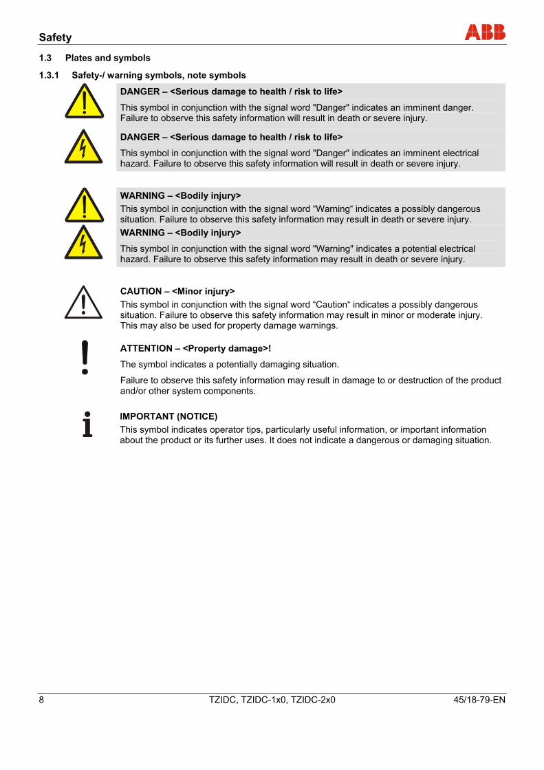
1.3.1 Safety-/ warning symbols, note symbols
DANGER – <Serious damage to health / risk to life>
This symbol in conjunction with the signal word "Danger" indicates an imminent danger. Failure to observe this safety information will result in death or severe injury.
DANGER – <Serious damage to health / risk to life>
This symbol in conjunction with the signal word "Danger" indicates an imminent electrical hazard. Failure to observe this safety information will result in death or severe injury.
WARNING – <Bodily injury> This symbol in conjunction with the signal word “Warning“ indicates a possibly dangerous situation. Failure to observe this safety information may result in death or severe injury.
WARNING – <Bodily injury>
This symbol in conjunction with the signal word "Warning" indicates a potential electrical hazard. Failure to observe this safety information may result in death or severe injury.
CAUTION – <Minor injury> This symbol in conjunction with the signal word “Caution“ indicates a possibly dangerous situation. Failure to observe this safety information may result in minor or moderate injury. This may also be used for property damage warnings.
ATTENTION – <Property damage>!
The symbol indicates a potentially damaging situation.
Failure to observe this safety information may result in damage to or destruction of the product and/or other system components.
IMPORTANT (NOTICE) This symbol indicates operator tips, particularly useful information, or important information about the product or its further uses. It does not indicate a dangerous or damaging situation.
Safety
45/18-79-EN TZIDC, TZIDC-1x0, TZIDC-2x0 9
1.4 Target groups and qualifications
Installation, commissioning, and maintenance of the product may only be performed by trained specialist personnel who have been authorized by the plant operator to do so. The specialist personnel must have read and understood the manual and comply with its instructions.
Prior to using corrosive and abrasive materials for measurement purposes, the operator must check the level of resistance of all parts coming into contact with the materials to be measured. ABB Automation Products GmbH will gladly support you in selecting the materials, but cannot accept any liability in doing so.
The operators must strictly observe the applicable national regulations with regards to installation, function tests, repairs, and maintenance of electrical products.
1.5 Explosion protection
Depending on the type of explosion protection, one of the following name plates is attached to the left of the positioner beside the main name plate. It shows the explosion protection and the unit's relevant EX certificate. More detailed information about the device can be found under "Certificates" in the appendix to the operating instructions.
Warning - General risks!
Observe the units' relevant technical data and special conditions in accordance with the applicable certificate.
Local operation
10 TZIDC, TZIDC-1x0, TZIDC-2x0 45/18-79-EN
2 Local operation
2.1 General
The positioner has two operating levels:
Operating level
On the operating level the positioner operates in one of four possible operating modes (two for automatic control and two for manual mode). Parameters cannot be changed or saved on this level.
Configuration level
On this level most of the parameters of the positioner can be changed locally. The PC is required to change the limit values for the movement counter, the travel counter, and the user-defined characteristic curve.
Caution - Risk
During external configuration via a PC, the positioner no longer responds to the setpoint current. Prior to external configuration, always move the actuator to the safe position and activate manual adjustment. To simplify operation, the parameters have been categorized into parameter groups through which you can navigate by means of push buttons (see the section titled "Displays and operating elements").
On the configuration level the active operating mode is deactivated. The I/P module is in neutral position. The control operation is inactive.
See the chapter titled "Configuration" for a detailed description of the individual parameter groups and parameters.
Local operation
45/18-79-EN TZIDC, TZIDC-1x0, TZIDC-2x0 11
2.2 Displays and operating elements
Positioners can be operated locally by means of four push buttons and a liquid crystal display.
Liquid crystal display
The liquid crystal display, with 160 segments, has been specially designed for the positioner.
Important
The display has been designed for a temperature range of -25 °C ... 80 °C. At temperatures outside this range the display is too sluggish and will be switched off.
conf
mA%
Co
1
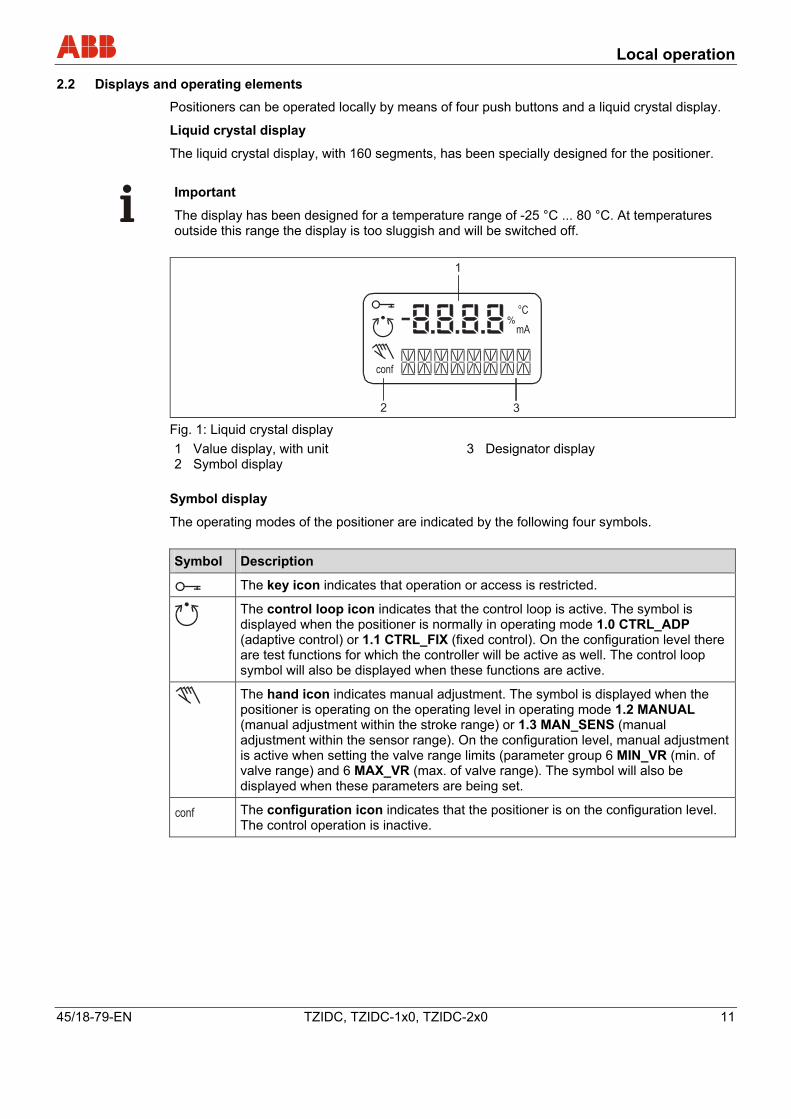
2 3 Fig. 1: Liquid crystal display 1 Value display, with unit 2 Symbol display
3 Designator display
Symbol display
The operating modes of the positioner are indicated by the following four symbols. Symbol Description
The key icon indicates that operation or access is restricted.
The control loop icon indicates that the control loop is active. The symbol is displayed when the positioner is normally in operating mode 1.0 CTRL_ADP (adaptive control) or 1.1 CTRL_FIX (fixed control). On the configuration level there are test functions for which the controller will be active as well. The control loop symbol will also be displayed when these functions are active.
The hand icon indicates manual adjustment. The symbol is displayed when the positioner is operating on the operating level in operating mode 1.2 MANUAL (manual adjustment within the stroke range) or 1.3 MAN_SENS (manual adjustment within the sensor range). On the configuration level, manual adjustment is active when setting the valve range limits (parameter group 6 MIN_VR (min. of valve range) and 6 MAX_VR (max. of valve range). The symbol will also be displayed when these parameters are being set.
conf The configuration icon indicates that the positioner is on the configuration level. The control operation is inactive.
Local operation
12 TZIDC, TZIDC-1x0, TZIDC-2x0 45/18-79-EN
Value display with unit
This 7-segment display with four digits indicates parameter values or parameter reference numbers. For values, the physical unit (°C, %, mA) is also displayed.
Designator display
This 14-segment display with eight digits indicates the designators of the parameters with their status, of the parameter groups, and of the operating modes.
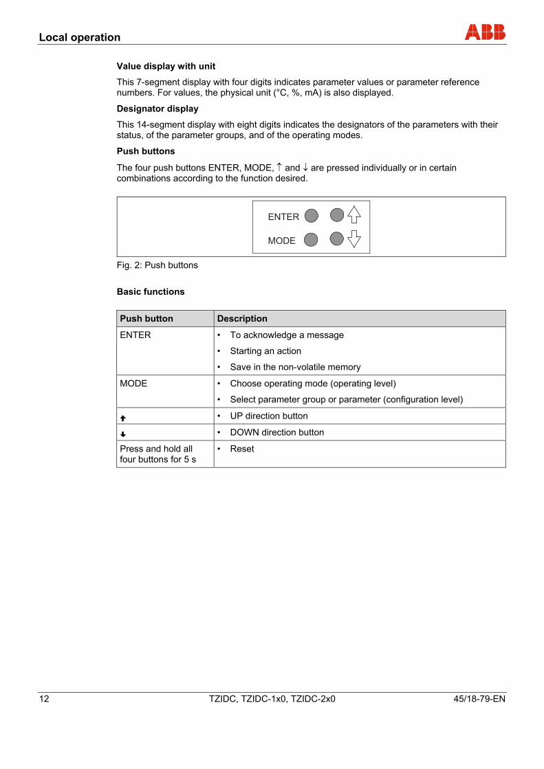
Push buttons
The four push buttons ENTER, MODE, ↑ and ↓ are pressed individually or in certain combinations according to the function desired.
ENTER
MODE
Fig. 2: Push buttons Basic functions Push button Description
ENTER • To acknowledge a message
• Starting an action
• Save in the non-volatile memory
MODE • Choose operating mode (operating level)
• Select parameter group or parameter (configuration level)
• UP direction button
• DOWN direction button
Press and hold all four buttons for 5 s
• Reset
Local operation
45/18-79-EN TZIDC, TZIDC-1x0, TZIDC-2x0 13
2.2.1 Functions on the operating level
Changing the mode (operating level)
1. Press and hold MODE.
The reference number (top) and the designator (bottom) of the active mode are displayed.
2. Additionally, press or until the reference number and the designator of the desired mode are shown on the display.
3. Release the buttons.
Important
The desired mode is only activated and saved in the non-volatile memory once the MODE button is released.
Adjusting the contrast (operating level)
1. Press and hold the ENTER button.
After approx. 1.5 seconds the display switches to the contrast value.
2. Additionally, press or to change the contrast.
The value selected is active immediately so that you can check the contrast in the display.
3. Release the buttons.
Once the ENTER button is released, the value is saved in the non-volatile memory.
Switching to the configuration level
1. Simultaneously press and hold the or buttons.
2. Press ENTER once and release it again. Press and hold ↑ and ↓ until the countdown from 3 to 0 is complete (duration: approx. 3 seconds).
Important
If you release the direction buttons before the countdown is complete, the configuration level will not be activated. 3. Release the or buttons.
The configuration level appears. The first parameter (ACTUATOR) of group 1 (STANDARD) is displayed. The configuration symbol is also shown on the display.

Local operation
14 TZIDC, TZIDC-1x0, TZIDC-2x0 45/18-79-EN
2.2.2 Functions on the configuration level
Switching to another parameter group
1. Simultaneously press and hold the MODE and ENTER buttons.
The display indicates the reference number (top) and the designator (bottom) of the current parameter group of the positioner.
2. Additionally, press or until the reference number and the designator of the desired parameter group are displayed.
3. Release all buttons.
The first parameter of the newly selected parameter group is displayed. The desired parameter can be adjusted within the group.
Selecting a parameter within a group
1. Press and hold MODE .
The display indicates the reference number (top) and the designator (bottom) of the current parameter.
2. Additionally, press or until the reference number and the designator of the desired parameter are displayed.
3. Release all buttons.
The display indicates the value of the selected parameter (top). At the bottom the designator is still shown. For parameters that can assume different states (e.g., ACTIVE or INACTIVE) the reference number is displayed at the top and the state at the bottom. The value/state of the parameter can be changed.
Changing a parameter
1. Press or until the desired value or state is shown.
Important
When keeping the respective direction button pressed, parameters with values are changed dynamically. The change rate is increased every second until the limit value of the parameter is reached.
Local operation
45/18-79-EN TZIDC, TZIDC-1x0, TZIDC-2x0 15
Saving data and exiting the configuration level
1. Select the EXIT parameter for the respective parameter group and set it to one of the two possible states using or :
NV_SAVE Activates your changes and saves them in the non-volatile memory. The positioner returns to the operating level.
CANCEL Changes are discarded. The positioner returns to the operating level.
Important
The parameters are only saved in the non-volatile memory by leaving the configuration level via EXIT -> SAVE.
Multiple parameters in different groups can also be changed sequentially. When leaving the last parameter group via EXIT -> SAVE, all previously made modifications are saved and applied. 2. Press and hold ENTER until the displayed countdown from 3 to 0 is
complete.
3. Release the ENTER button.
The positioner returns to the operating level. The configuration level was accessed from this mode.
Depending on the selection the data is saved in the non-volatile memory or discarded. During the save operation a plausibility check is performed. If an error occurs during the check or while data is being saved, an error message is displayed (see the chapter titled "Error messages").
Starting an action
1. Press and hold ENTER until the displayed countdown from 3 to 0 is complete.
2. Release the ENTER button. The selected action is started.
Important
If you release ENTER before the countdown is complete, the action will not be started.
Local operation
16 TZIDC, TZIDC-1x0, TZIDC-2x0 45/18-79-EN
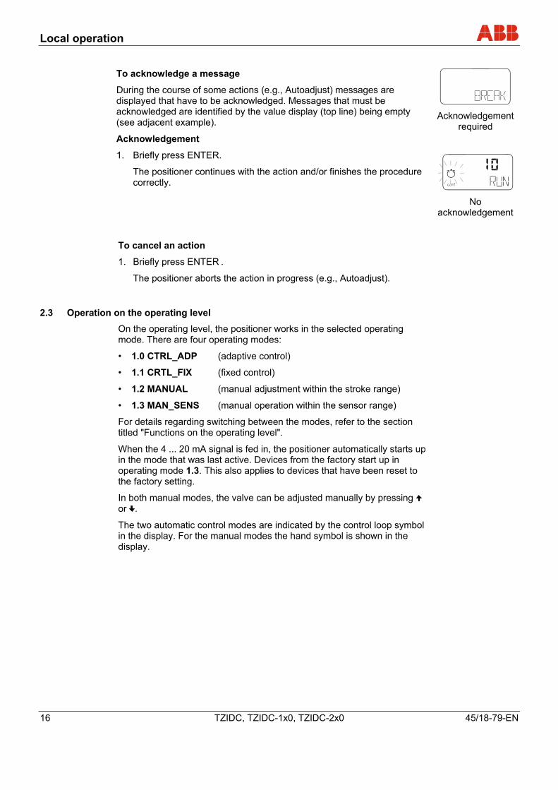
To acknowledge a message
During the course of some actions (e.g., Autoadjust) messages are displayed that have to be acknowledged. Messages that must be acknowledged are identified by the value display (top line) being empty (see adjacent example).
Acknowledgement
1. Briefly press ENTER.
The positioner continues with the action and/or finishes the procedure correctly.
conf
mA%
C°
Acknowledgement
required
conf
mA%
C°
No
acknowledgement
To cancel an action
1. Briefly press ENTER .
The positioner aborts the action in progress (e.g., Autoadjust).
2.3 Operation on the operating level
On the operating level, the positioner works in the selected operating mode. There are four operating modes:
• 1.0 CTRL_ADP (adaptive control)
• 1.1 CRTL_FIX (fixed control)
• 1.2 MANUAL (manual adjustment within the stroke range)
• 1.3 MAN_SENS (manual operation within the sensor range)
For details regarding switching between the modes, refer to the section titled "Functions on the operating level".
When the 4 ... 20 mA signal is fed in, the positioner automatically starts up in the mode that was last active. Devices from the factory start up in operating mode 1.3. This also applies to devices that have been reset to the factory setting.
In both manual modes, the valve can be adjusted manually by pressing or .
The two automatic control modes are indicated by the control loop symbol in the display. For the manual modes the hand symbol is shown in the display.
Local operation
45/18-79-EN TZIDC, TZIDC-1x0, TZIDC-2x0 17
2.4 Operating modes
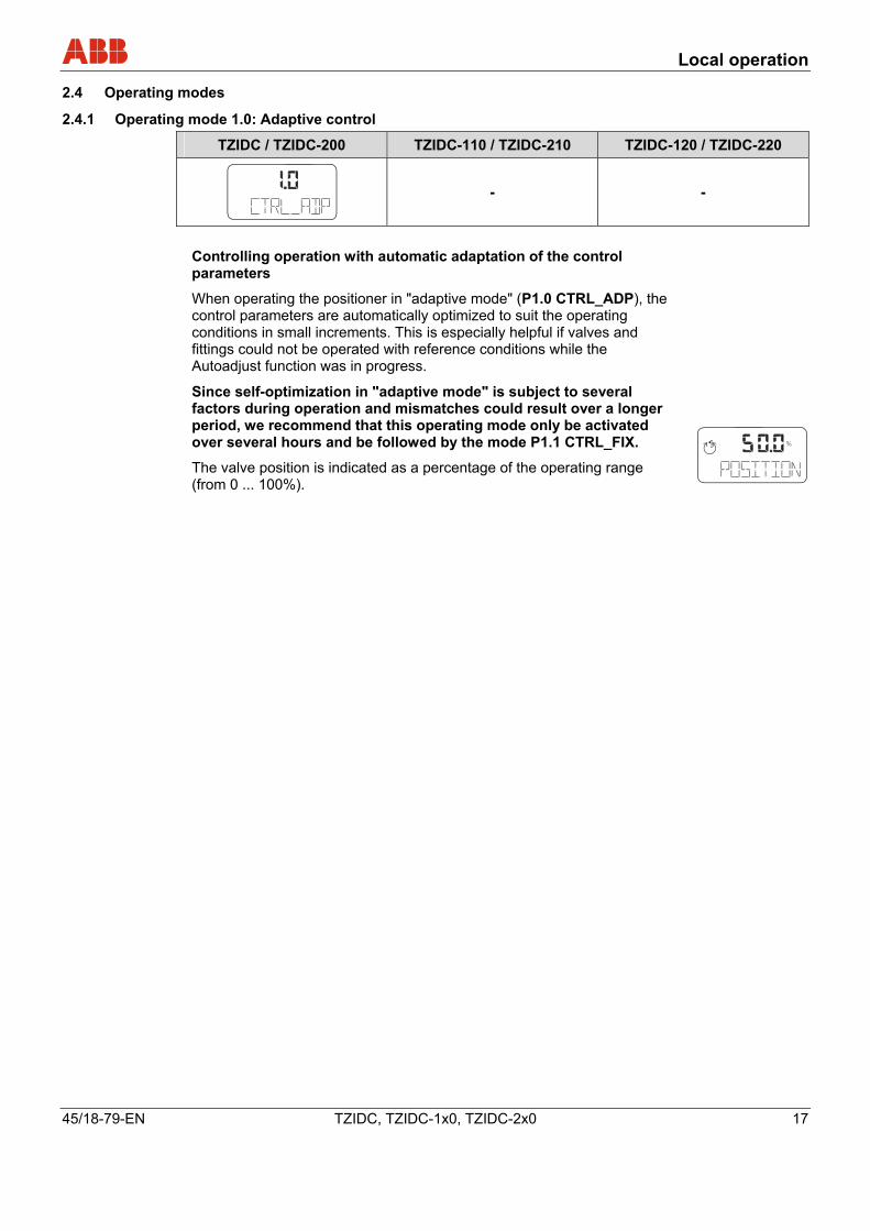
2.4.1 Operating mode 1.0: Adaptive control
TZIDC / TZIDC-200 TZIDC-110 / TZIDC-210 TZIDC-120 / TZIDC-220
conf
mA%
C°
- -
Controlling operation with automatic adaptation of the control parameters
When operating the positioner in "adaptive mode" (P1.0 CTRL_ADP), the control parameters are automatically optimized to suit the operating conditions in small increments. This is especially helpful if valves and fittings could not be operated with reference conditions while the Autoadjust function was in progress.
Since self-optimization in "adaptive mode" is subject to several factors during operation and mismatches could result over a longer period, we recommend that this operating mode only be activated over several hours and be followed by the mode P1.1 CTRL_FIX.
The valve position is indicated as a percentage of the operating range (from 0 ... 100%).
conf
mA%
C°
Local operation
18 TZIDC, TZIDC-1x0, TZIDC-2x0 45/18-79-EN
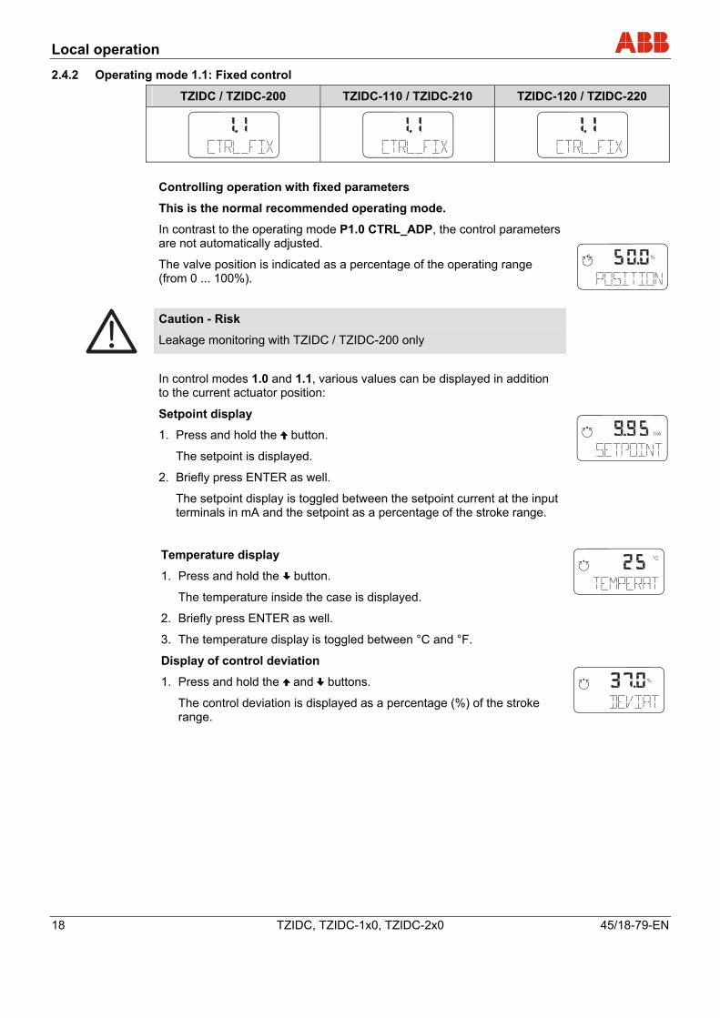
2.4.2 Operating mode 1.1: Fixed control
TZIDC / TZIDC-200 TZIDC-110 / TZIDC-210 TZIDC-120 / TZIDC-220
conf
mA%
C°
conf
mA%
C°
conf
mA%
C°
Controlling operation with fixed parameters
This is the normal recommended operating mode.
In contrast to the operating mode P1.0 CTRL_ADP, the control parameters are not automatically adjusted.
The valve position is indicated as a percentage of the operating range (from 0 ... 100%).
conf
mA%
C°
Caution - Risk
Leakage monitoring with TZIDC / TZIDC-200 only
In control modes 1.0 and 1.1, various values can be displayed in addition to the current actuator position:
Setpoint display
1. Press and hold the button.
The setpoint is displayed.
2. Briefly press ENTER as well.
The setpoint display is toggled between the setpoint current at the input terminals in mA and the setpoint as a percentage of the stroke range.
conf
mA%
C°
Temperature display
1. Press and hold the button.
The temperature inside the case is displayed.
2. Briefly press ENTER as well.
3. The temperature display is toggled between °C and °F.
Display of control deviation
1. Press and hold the and buttons.
The control deviation is displayed as a percentage (%) of the stroke range.
conf
mA%
C°
conf
mA%
C°
Local operation
45/18-79-EN TZIDC, TZIDC-1x0, TZIDC-2x0 19
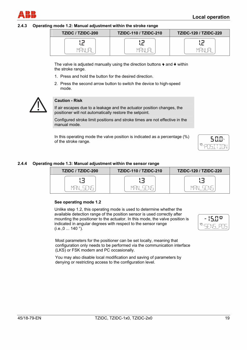
2.4.3 Operating mode 1.2: Manual adjustment within the stroke range
TZIDC / TZIDC-200 TZIDC-110 / TZIDC-210 TZIDC-120 / TZIDC-220
conf
mA%
C°
conf
mA%
C°
conf
mA%
C°
The valve is adjusted manually using the direction buttons and within the stroke range.
1. Press and hold the button for the desired direction.
2. Press the second arrow button to switch the device to high-speed mode.
Caution - Risk
If air escapes due to a leakage and the actuator position changes, the positioner will not automatically restore the setpoint.
Configured stroke limit positions and stroke times are not effective in the manual mode.
In this operating mode the valve position is indicated as a percentage (%) of the stroke range.
conf
mA%
C°
2.4.4 Operating mode 1.3: Manual adjustment within the sensor range
TZIDC / TZIDC-200 TZIDC-110 / TZIDC-210 TZIDC-120 / TZIDC-220
conf
mA%
C°
conf
mA%
C°
conf
mA%
C°
See operating mode 1.2
Unlike step 1.2, this operating mode is used to determine whether the available detection range of the position sensor is used correctly after mounting the positioner to the actuator. In this mode, the valve position is indicated in angular degrees with respect to the sensor range (i.e.,0 ... 140 °).
conf
mA%
C°
Most parameters for the positioner can be set locally, meaning that configuration only needs to be performed via the communication interface (LKS) or FSK modem and PC occasionally.
You may also disable local modification and saving of parameters by denying or restricting access to the configuration level.
Local operation
20 TZIDC, TZIDC-1x0, TZIDC-2x0 45/18-79-EN
2.5 Inhibiting operation
Positioner operation can be inhibited completely or partially via the digital input and the FUNCTION parameter in parameter group 10 (DIG_IN (digital input)). This allows the user to prevent or restrict operating actions of unauthorized personnel as desired. When operation is disabled in this way, the key symbol is indicated in the display.
The following levels of configuration locks are possible:
Inhibiting the local configuration
Local operation on the operating level and remote operation and configuration via a PC are still possible.
Inhibiting all local operating functions
No local operating actions can be executed. Both the operating level and the configuration level are locked. Remote operation and setting of parameters via a PC is still possible.
Inhibiting local operation and remote configuration
It is not possible to operate or configure the positioner locally or configure it using a PC.
Important
This inhibit function can only be deactivated when a voltage of 12 ... 24 V is applied at the digital input of the positioner (see Function selection in parameter group 10).

Configuration
45/18-79-EN TZIDC, TZIDC-1x0, TZIDC-2x0 21
K
3 Configuration
3.1 General information
Most parameters for the positioner can be set locally, meaning that configuration only needs to be performed via the communication interface (LKS) or FSK modem and PC occasionally.
You may also deny or restrict local modification and saving of parameters by completely or partially blocking access to the configuration level (see "Inhibiting operation" in the section titled "Local operation", and the description of the Function selection parameter in parameter group 10).
To simplify the process, the different parameters are grouped as follows: ID TZIDC /
TZIDC-200 TZIDC-110 / TZIDC-210
TZIDC-120 / TZIDC-220
Designator Name
P1._
P2._
P3._
P4._
P5._
P6._
P7._
P8._
P9._
P10._
P11._
X
X
X
X
X
X
X
X
X
X
x
X
X
X
-
-
X
X
-
-
-
x
X
X
X
-
-
X
X
-
-
-
x
STANDARD
SETPOINT
ACTUATOR
MESSAGES
ALARMS
MAN_ADJ
CTRL_PAR
ANLG_OUT
DIG_OUT
DIG_IN
FS / IP
Standard
Setpoint
Actuator
Messages
Alarms
Manual adjustment
Control parameters
Analog output
Digital output
Digital input
Factory setting, I/P type
The following sections provide an overview (in tabular and graphical format) of the overall structure of the parameter groups and parameters.
Configuration
22 TZIDC, TZIDC-1x0, TZIDC-2x0 45/18-79-EN
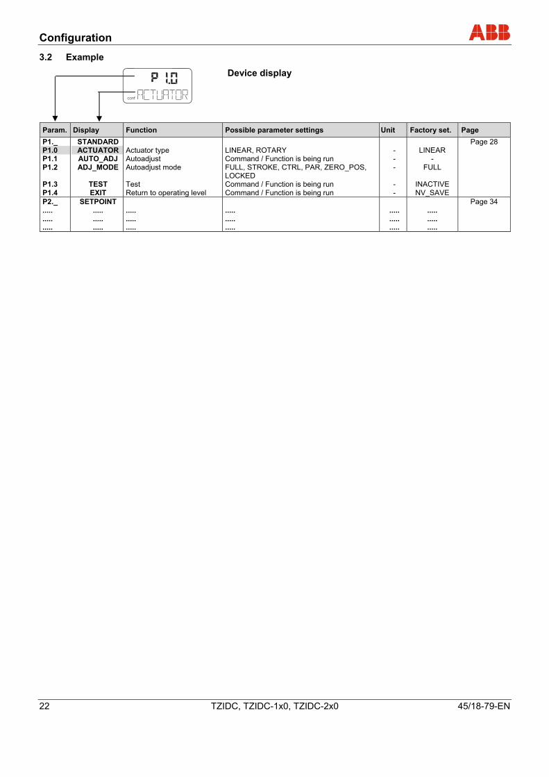
3.2 Example
conf
Device display
Param. Display Function Possible parameter settings Unit Factory set. Page P1._ P1.0 P1.1 P1.2 P1.3 P1.4
STANDARD ACTUATOR AUTO_ADJ ADJ_MODE
TEST EXIT
Actuator type Autoadjust Autoadjust mode Test Return to operating level
LINEAR, ROTARY Command / Function is being run FULL, STROKE, CTRL, PAR, ZERO_POS, LOCKED Command / Function is being run Command / Function is being run
- - - - -
LINEAR
- FULL
INACTIVE NV_SAVE
Page 28
P2._ ..... ..... .....
SETPOINT ..... ..... .....
..... ..... .....
..... ..... .....
..... ..... .....
..... ..... .....
Page 34
Configuration
45/18-79-EN TZIDC, TZIDC-1x0, TZIDC-2x0 23
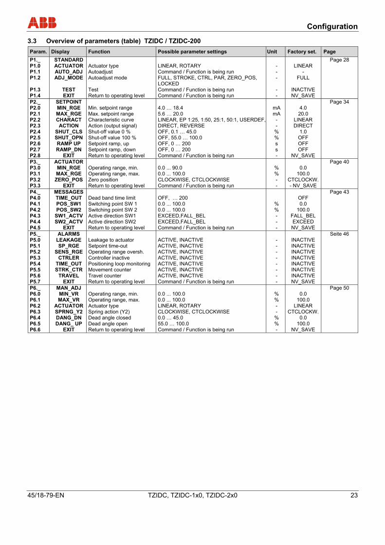
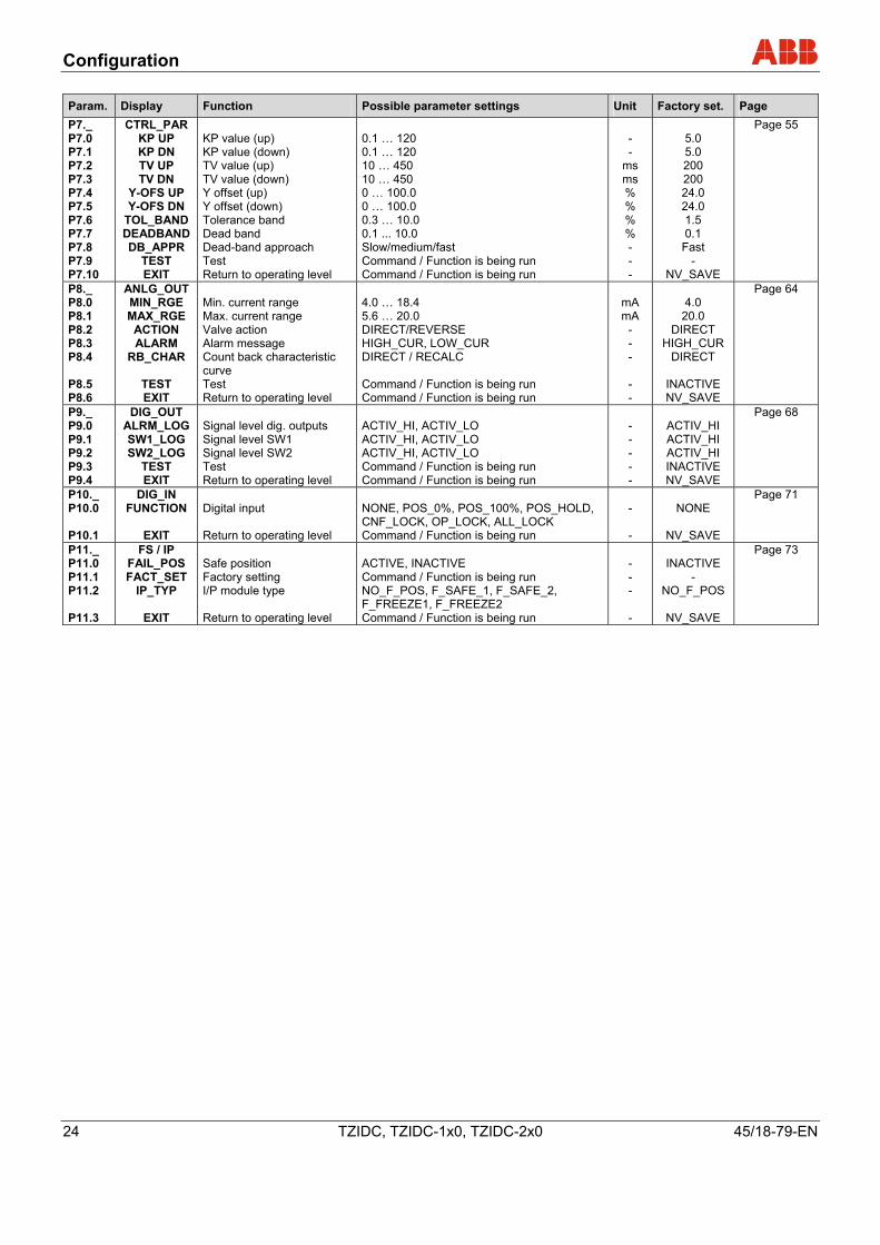
3.3 Overview of parameters (table) TZIDC / TZIDC-200
Param. Display Function Possible parameter settings Unit Factory set. Page P1._ P1.0 P1.1 P1.2 P1.3 P1.4
STANDARD ACTUATOR AUTO_ADJ ADJ_MODE
TEST EXIT
Actuator type Autoadjust Autoadjust mode Test Return to operating level
LINEAR, ROTARY Command / Function is being run FULL, STROKE, CTRL, PAR, ZERO_POS, LOCKED Command / Function is being run Command / Function is being run
- - - - -
LINEAR
- FULL
INACTIVE NV_SAVE
Page 28
P2._ P2.0 P2.1 P2.2 P2.3 P2.4 P2.5 P2.6 P2.7 P2.8
SETPOINT MIN_RGE MAX_RGE CHARACT ACTION
SHUT_CLS SHUT_OPN RAMP UP RAMP_DN
EXIT
Min. setpoint range Max. setpoint range Characteristic curve Action (output signal) Shut-off value 0 % Shut-off value 100 % Setpoint ramp, up Setpoint ramp, down Return to operating level
4.0 … 18.4 5.6 … 20.0 LINEAR, EP 1:25, 1:50, 25:1, 50:1, USERDEF,DIRECT, REVERSE OFF, 0.1 … 45.0 OFF, 55.0 … 100.0 OFF, 0 … 200 OFF, 0 … 200 Command / Function is being run
mA mA
- -
% % s s -
4.0
20.0 LINEAR DIRECT
1.0 OFF OFF OFF
NV_SAVE
Page 34
P3._ P3.0 P3.1 P3.2 P3.3
ACTUATOR MIN_RGE MAX_RGE ZERO_POS
EXIT
Operating range, min. Operating range, max. Zero position Return to operating level
0.0 ... 90.0 0.0 ... 100.0 CLOCKWISE, CTCLOCKWISE Command / Function is being run
% % - -
0.0
100.0 CTCLOCKW.- NV_SAVE
Page 40
P4._ P4.0 P4.1 P4.2 P4.3 P4.4 P4.5
MESSAGES TIME_OUT POS_SW1 POS_SW2
SW1_ACTV SW2_ACTV
EXIT
Dead band time limit Switching point SW 1 Switching point SW 2 Active direction SW1 Active direction SW2 Return to operating level
OFF, … 200 0.0 ... 100.0 0.0 ... 100.0 EXCEED,FALL_BEL EXCEED,FALL_BEL Command / Function is being run
% % - - -
OFF 0.0
100.0 FALL_BEL EXCEED NV_SAVE
Page 43
P5._ P5.0 P5.1 P5.2 P5.3 P5.4 P5.5 P5.6 P5.7
ALARMS LEAKAGE SP_RGE
SENS_RGE CTRLER
TIME_OUT STRK_CTR
TRAVEL EXIT
Leakage to actuator Setpoint time-out Operating range oversh. Controller inactive Positioning loop monitoring Movement counter Travel counter Return to operating level
ACTIVE, INACTIVE ACTIVE, INACTIVE ACTIVE, INACTIVE ACTIVE, INACTIVE ACTIVE, INACTIVE ACTIVE, INACTIVE ACTIVE, INACTIVE Command / Function is being run
- - - - - - - -
INACTIVE INACTIVE INACTIVE INACTIVE INACTIVE INACTIVE INACTIVE NV_SAVE
Seite 46
P6._ P6.0 P6.1 P6.2 P6.3 P6.4 P6.5 P6.6
MAN_ADJ MIN_VR MAX_VR
ACTUATOR SPRNG_Y2 DANG_DN DANG_ UP
EXIT
Operating range, min. Operating range, max. Actuator type Spring action (Y2) Dead angle closed Dead angle open Return to operating level
0.0 ... 100.0 0.0 ... 100.0 LINEAR, ROTARY CLOCKWISE, CTCLOCKWISE 0.0 … 45.0 55.0 … 100.0 Command / Function is being run
% % - -
% % -
0.0
100.0 LINEAR
CTCLOCKW.0.0
100.0 NV_SAVE
Page 50
Configuration
24 TZIDC, TZIDC-1x0, TZIDC-2x0 45/18-79-EN
Param. Display Function Possible parameter settings Unit Factory set. Page P7._ P7.0 P7.1 P7.2 P7.3 P7.4 P7.5 P7.6 P7.7 P7.8 P7.9 P7.10
CTRL_PAR KP UP KP DN TV UP TV DN
Y-OFS UP Y-OFS DN
TOL_BAND DEADBAND DB_APPR
TEST EXIT
KP value (up) KP value (down) TV value (up) TV value (down) Y offset (up) Y offset (down) Tolerance band Dead band Dead-band approach Test Return to operating level
0.1 … 120 0.1 … 120 10 … 450 10 … 450 0 … 100.0 0 … 100.0 0.3 … 10.0 0.1 ... 10.0 Slow/medium/fast Command / Function is being run Command / Function is being run
- -
ms ms % % % % - - -
5.0 5.0 200 200 24.0 24.0 1.5 0.1
Fast -
NV_SAVE
Page 55
P8._ P8.0 P8.1 P8.2 P8.3 P8.4 P8.5 P8.6
ANLG_OUT MIN_RGE MAX_RGE ACTION ALARM
RB_CHAR
TEST EXIT
Min. current range Max. current range Valve action Alarm message Count back characteristic curve Test Return to operating level
4.0 … 18.4 5.6 … 20.0 DIRECT/REVERSE HIGH_CUR, LOW_CUR DIRECT / RECALC Command / Function is being run Command / Function is being run
mA mA
- - - - -
4.0
20.0 DIRECT
HIGH_CUR DIRECT
INACTIVE NV_SAVE
Page 64
P9._ P9.0 P9.1 P9.2 P9.3 P9.4
DIG_OUT ALRM_LOG SW1_LOG SW2_LOG
TEST EXIT
Signal level dig. outputs Signal level SW1 Signal level SW2 Test Return to operating level
ACTIV_HI, ACTIV_LO ACTIV_HI, ACTIV_LO ACTIV_HI, ACTIV_LO Command / Function is being run Command / Function is being run
- - - - -
ACTIV_HI ACTIV_HI ACTIV_HI INACTIVE NV_SAVE
Page 68
P10._ P10.0 P10.1
DIG_IN FUNCTION
EXIT
Digital input Return to operating level
NONE, POS_0%, POS_100%, POS_HOLD, CNF_LOCK, OP_LOCK, ALL_LOCK Command / Function is being run
- -
NONE
NV_SAVE
Page 71
P11._ P11.0 P11.1 P11.2 P11.3
FS / IP FAIL_POS FACT_SET
IP_TYP
EXIT
Safe position Factory setting I/P module type Return to operating level
ACTIVE, INACTIVE Command / Function is being run NO_F_POS, F_SAFE_1, F_SAFE_2, F_FREEZE1, F_FREEZE2 Command / Function is being run
- - - -
INACTIVE
- NO_F_POS
NV_SAVE
Page 73
Configuration
45/18-79-EN TZIDC, TZIDC-1x0, TZIDC-2x0 25
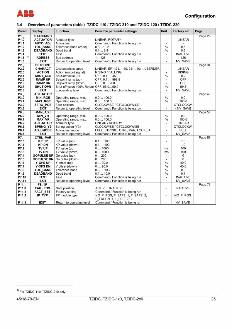
3.4 Overview of parameters (table) TZIDC-110 / TZIDC 210 and TZIDC-120 / TZIDC-220
Param. Display Function Possible parameter settings Unit Factory set. Page P1._ P1.0 P1.1 P1.2 P1.3 P1.4 P1.5 1) P1.6
STANDARD ACTUATOR AUTO_ADJ TOL_BAND DEADBAND
TEST ADRESS
EXIT
Actuator type Autoadjust Tolerance band (zone) Dead band Test Bus address Return to operating level
LINEAR, ROTARY Command / Function is being run 0.3 ...10.2 0.1 ... 9.8 Command / Function is being run 1 ...126 Command / Function is being run
- -
% % - - -
LINEAR
- 0.8 0.5
INACTIVE 126
NV_SAVE
Page 28
P2._ P2.2 P2.3 P2.4 P2.5 P2.6 P2.7 P2.8
SETPOINT CHARACT ACTION
SHUT_CLS RAMP UP RAMP DN SHUT OPN
EXIT
Characteristic curve Action (output signal) Shut-off value 0 % Setpoint ramp (up) Setpoint ramp (down) Shut-off value 100% Returnto operating level
LINEAR, EP 1:25, 1:50, 25:1, 50:1, USERDEF,RISING / FALLING OFF, 0.1 … 45.0 OFF, 0.1 … 999.9 OFF, 0 … 200 OFF, 55.0…99.9 Command / Function is being run
- -
% - -
% -
LINEAR RISING
0.2 OFF OFF 99.8
NV_SAVE
Page 34
P3._ P3.0 P3.1 P3.2 P3.3
ACTUATOR MIN_RGE MAX_RGE ZERO_POS
EXIT
Operating range, min. Operating range, max. Zero position Return to operating level
0.0 ... 100.0 0.0 ... 100.0 CLOCKWISE / CTCLOCKWISE Command / Function is being run
% % - -
0.0
100.0 CTCLOCKW.- NV_SAVE
Page 40
P6._ P6.0 P6.1 P6.2 P6.3 P6.4 P6.5
MAN_ADJ MIN_VR MAX_VR
ACTUATOR SPRNG_Y2 ADJ_MODE
EXIT
Operating range, min. Operating range, max. Actuator type Spring action (Y2) Autoadjust mode Return to operating level
0.0 ... 100.0 0.0 ... 100.0 LINEAR / ROTARY CLOCKWISE / CTCLOCKWISE FULL, STROKE, CTRL, PAR, LOCKED Command / Function is being run
% % - - - -
0.0
100.0 LINEAR
CTCLOCKW.FULL
NV_SAVE
Page 50
P7._ P7.0 P7.1 P7.2 P7.3 P7.4 P7.5 P7.6 P7.7 P7.9 P1.3 P7.10 P7.11
CTRL_PAR KP UP KP DN TV UP TV DN
GOPULSE UP GOPULSE DN
Y-OFS UP Y-OFS DN
TOL_BAND DEADBAND
TEST EXIT
KP value (up) KP value (down) TV value (up) TV value (down) Go pulse (up) Go pulse (down) Y offset (up) Y offset (down) Tolerance band Dead band Test Return to operating level
0.1 … 100 0.1 … 100 0 … 1000 0 … 1000 0 ... 200 0 ... 200 0 … 90.0 0 … 90.0 0.3 … 10.2 0.1 ... 10.0 Command / Function is being run Command / Function is being run
- -
ms ms - -
% % % % - -
1.0 1.0 100 100 0 0
40.0 40.0 0.8 0.1
INACTIVE NV_SAVE
Page 55
P11._ P11.0 P11.1 P11.2 P11.3
FS / IP FAIL_POS FACT_SET
IP_TYP
EXIT
Safe position Factory setting I/P module type Return to operating level
ACTIVE / INACTIVE Command / Function is being run NO_F_POS, F_SAFE_1, F_SAFE_2, F_FREEZE1, F_FREEZE2 Command / Function is being run
- - - -
INACTIVE
- NO_F_POS
NV_SAVE
Page 73
1) For TZIDC-110 / TZIDC-210 only
Configuration
26 TZIDC, TZIDC-1x0, TZIDC-2x0 45/18-79-EN
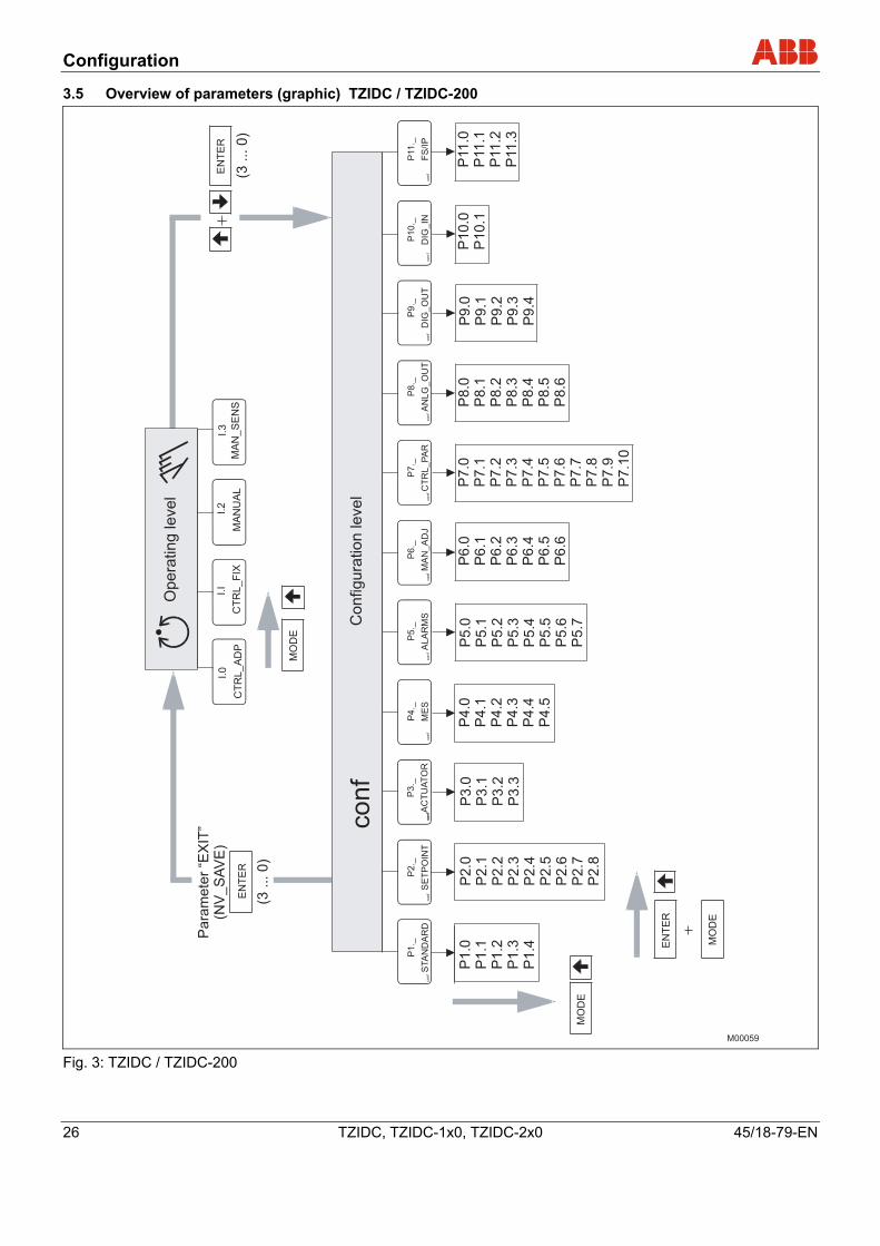
3.5 Overview of parameters (graphic) TZIDC / TZIDC-200
M00059
I.3
co
nf
mA
%C°
co
nf
co
nf
co
nf
co
nf
co
nf
co
nf
co
nf
co
nf
co
nfE
NT
ER
MO
DE
EN
TE
R
(3...0)
(3...0)
conf
I.0
CT
RL_A
DP
CT
RL_F
IX
I.2
MA
NU
AL
MA
N_S
EN
S
I.I
EN
TE
R
Para
mete
r“E
XIT
”(N
V_S
AV
E)
P1.0
P1.1
P1.2
P1.3
P1.4
P4.0
P4.1
P4.2
P4.3
P4.4
P4.5
P2.0
P2.1
P2.2
P2.3
P2.4
P2.5
P2.6
P2.7
P2.8
P3.0
P3.1
P3.2
P3.3
P5.0
P5.1
P5.2
P5.3
P5.4
P5.5
P5.6
P5.7
P6.0
P6.1
P6.2
P6.3
P6.4
P6.5
P6.6
P7.0
P7.1
P7.2
P7.3
P7.4
P7.5
P7.6
P7.7
P7.8
P7.9
P7.1
0
P8.0
P8.1
P8.2
P8.3
P8.4
P8.5
P8.6
P9.0
P9.1
P9.2
P9.3
P9.4
P10.0
P10.1
P11.0
P11.1
P11.2
P11.3
co
nf
co
nf
co
nf
P1
._
STA
ND
AR
D
P2
._
SE
TP
OIN
T
P3
._
AC
TU
AT
OR
P4
._
ME
S
P5
._
AL
AR
MS
P6
._
MA
N_
AD
J
P7
._
CT
RL
_P
AR
P8
._
AN
LG
_O
UT
P9
._
DIG
_O
UT
P1
0._
DIG
_IN
P11
._
FS
/IP
MO
DE
MO
DE
Co
nfig
ura
tio
nle
ve
l
Op
era
tin
gle
ve
l
Fig. 3: TZIDC / TZIDC-200
Configuration
45/18-79-EN TZIDC, TZIDC-1x0, TZIDC-2x0 27
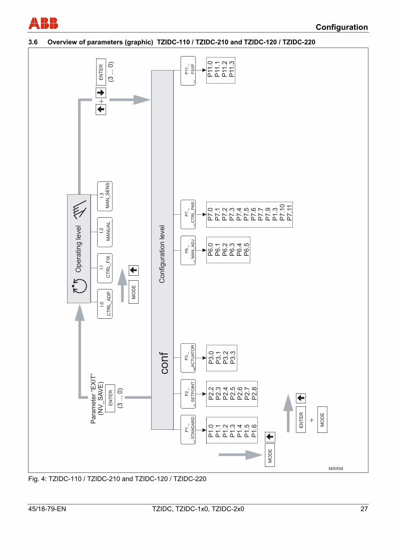
3.6 Overview of parameters (graphic) TZIDC-110 / TZIDC-210 and TZIDC-120 / TZIDC-220
M00558
I.3
co
nf
mA
%C°
co
nf
co
nf
co
nf
co
nfE
NT
ER
MO
DE
EN
TE
R
(3...0)
(3...0)
co
nf
I.0
CT
RL_A
DP
CT
RL_F
IX
I.2
MA
NU
AL
MA
N_S
EN
S
I.I
EN
TE
R
Para
mete
r“E
XIT
”(N
V_S
AV
E)
P1.0
P1.1
P1.2
P1.3
P1.4
P1.5
P1.6
P2.2
P2.3
P2.4
P2.5
P2.6
P2.7
P2.8
P3.0
P3.1
P3.2
P3.3
P6.0
P6.1
P6.2
P6.3
P6.4
P6.5
P7.0
P7.1
P7.2
P7.3
P7.4
P7.5
P7.6
P7.7
P7.9
P1.3
P7.1
0P
7.1
1
P11.0
P11.1
P11.2
P11.3
co
nf
co
nf
co
nf
P1
._
STA
ND
AR
D
P2
._
SE
TP
OIN
T
P3
._
AC
TU
AT
OR
P6
._
MA
N_
AD
J
P7
._
CT
RL
_P
AR
P11
._
FS
/IP
MO
DE
MO
DE
Configura
tion
level
Opera
ting
level
Fig. 4: TZIDC-110 / TZIDC-210 and TZIDC-120 / TZIDC-220
Configuration
28 TZIDC, TZIDC-1x0, TZIDC-2x0 45/18-79-EN
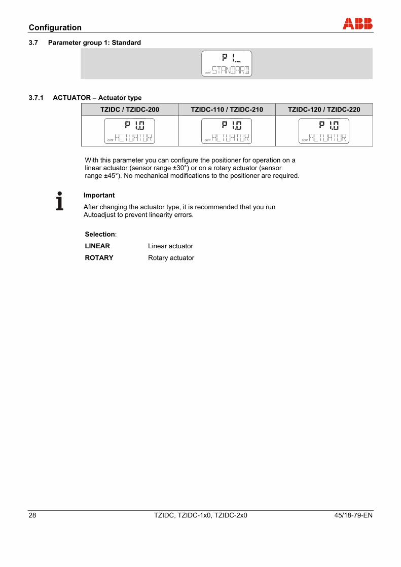
3.7 Parameter group 1: Standard
conf
3.7.1 ACTUATOR – Actuator type
TZIDC / TZIDC-200 TZIDC-110 / TZIDC-210 TZIDC-120 / TZIDC-220
conf conf conf With this parameter you can configure the positioner for operation on a linear actuator (sensor range ±30°) or on a rotary actuator (sensor range ±45°). No mechanical modifications to the positioner are required.
Important
After changing the actuator type, it is recommended that you run Autoadjust to prevent linearity errors. Selection:
LINEAR Linear actuator
ROTARY Rotary actuator
Configuration
45/18-79-EN TZIDC, TZIDC-1x0, TZIDC-2x0 29
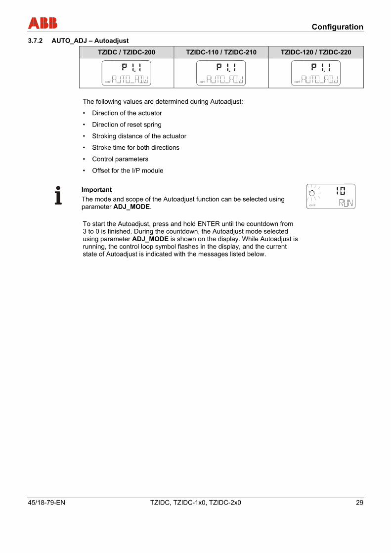
3.7.2 AUTO_ADJ – Autoadjust
TZIDC / TZIDC-200 TZIDC-110 / TZIDC-210 TZIDC-120 / TZIDC-220
conf
mA%
C°
conf
mA%
C°
conf
mA%
C°
The following values are determined during Autoadjust:
• Direction of the actuator
• Direction of reset spring
• Stroking distance of the actuator
• Stroke time for both directions
• Control parameters
• Offset for the I/P module
Important The mode and scope of the Autoadjust function can be selected using parameter ADJ_MODE. conf
mA%
C°
To start the Autoadjust, press and hold ENTER until the countdown from 3 to 0 is finished. During the countdown, the Autoadjust mode selected using parameter ADJ_MODE is shown on the display. While Autoadjust is running, the control loop symbol flashes in the display, and the current state of Autoadjust is indicated with the messages listed below.
Configuration
30 TZIDC, TZIDC-1x0, TZIDC-2x0 45/18-79-EN
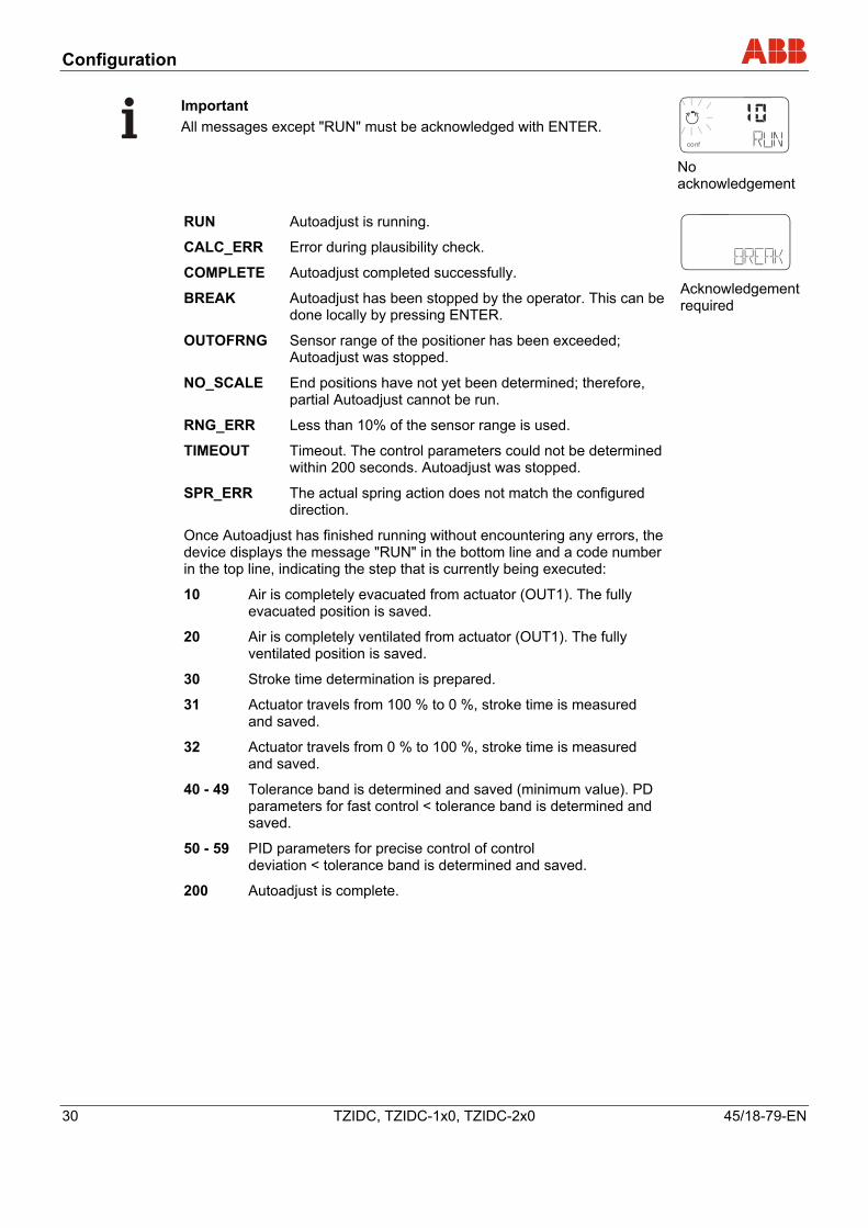
Important All messages except "RUN" must be acknowledged with ENTER.
conf
mA%
C°
No acknowledgement
RUN Autoadjust is running.
CALC_ERR Error during plausibility check.
COMPLETE Autoadjust completed successfully.
BREAK Autoadjust has been stopped by the operator. This can be done locally by pressing ENTER.
OUTOFRNG Sensor range of the positioner has been exceeded; Autoadjust was stopped.
NO_SCALE End positions have not yet been determined; therefore, partial Autoadjust cannot be run.
RNG_ERR Less than 10% of the sensor range is used.
TIMEOUT Timeout. The control parameters could not be determined within 200 seconds. Autoadjust was stopped.
SPR_ERR The actual spring action does not match the configured direction.
Once Autoadjust has finished running without encountering any errors, the device displays the message "RUN" in the bottom line and a code number in the top line, indicating the step that is currently being executed:
10 Air is completely evacuated from actuator (OUT1). The fully evacuated position is saved.
20 Air is completely ventilated from actuator (OUT1). The fully ventilated position is saved.
30 Stroke time determination is prepared.
31 Actuator travels from 100 % to 0 %, stroke time is measured and saved.
32 Actuator travels from 0 % to 100 %, stroke time is measured and saved.
40 - 49 Tolerance band is determined and saved (minimum value). PD parameters for fast control < tolerance band is determined and saved.
50 - 59 PID parameters for precise control of control deviation < tolerance band is determined and saved.
200 Autoadjust is complete.
con f Acknowledgement required
Configuration
45/18-79-EN TZIDC, TZIDC-1x0, TZIDC-2x0 31
If a partial run of Autoadjust has been selected (see parameter DANG_DN), the following code numbers are shown:
Stops only: Steps 10 – 32 and step 200
Parameters only: Steps 40 – 120 and step 200
Zero only:
10 Air is completely evacuated from actuator (OUT1). The fully evacuated position is saved.
200 Autoadjust is complete.
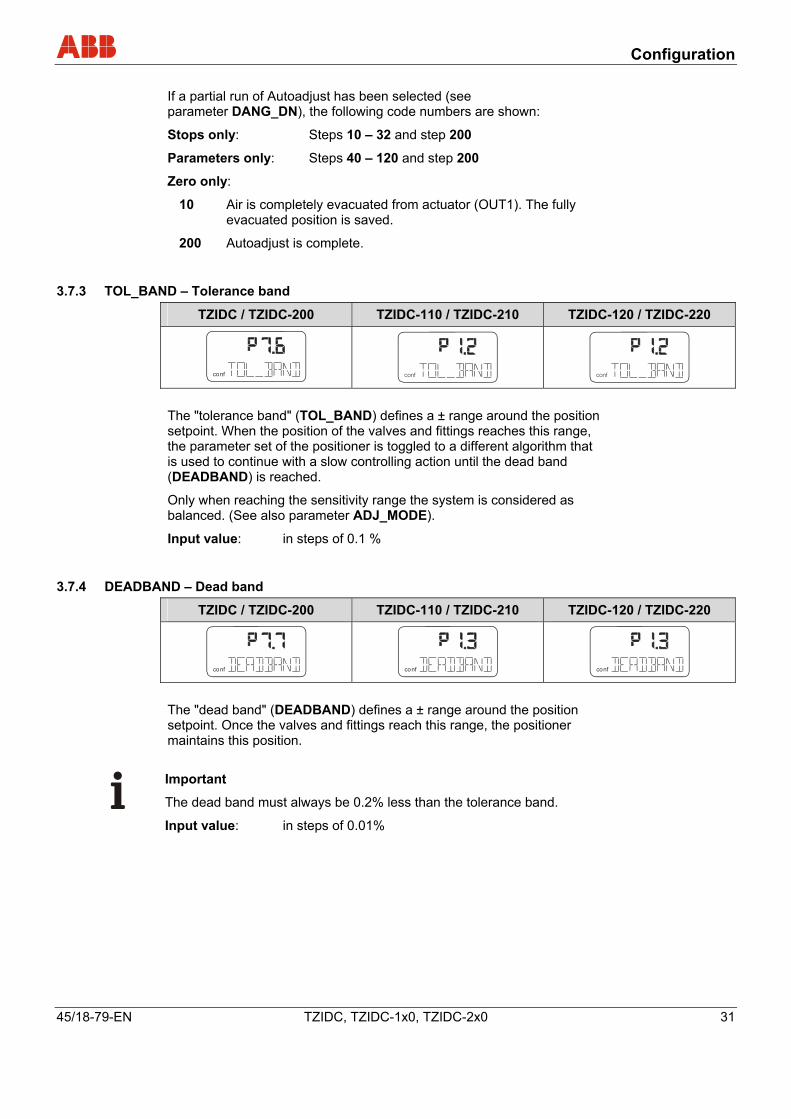
3.7.3 TOL_BAND – Tolerance band
TZIDC / TZIDC-200 TZIDC-110 / TZIDC-210 TZIDC-120 / TZIDC-220
conf
mA%
C°
conf
mA%
C°
conf
mA%
C°
The "tolerance band" (TOL_BAND) defines a ± range around the position setpoint. When the position of the valves and fittings reaches this range, the parameter set of the positioner is toggled to a different algorithm that is used to continue with a slow controlling action until the dead band (DEADBAND) is reached.
Only when reaching the sensitivity range the system is considered as balanced. (See also parameter ADJ_MODE).
Input value: in steps of 0.1 %
3.7.4 DEADBAND – Dead band
TZIDC / TZIDC-200 TZIDC-110 / TZIDC-210 TZIDC-120 / TZIDC-220
conf
mA%
C°
conf
mA%
C°
conf
mA%
C°
The "dead band" (DEADBAND) defines a ± range around the position setpoint. Once the valves and fittings reach this range, the positioner maintains this position.
Important
The dead band must always be 0.2% less than the tolerance band.
Input value: in steps of 0.01%
Configuration
32 TZIDC, TZIDC-1x0, TZIDC-2x0 45/18-79-EN
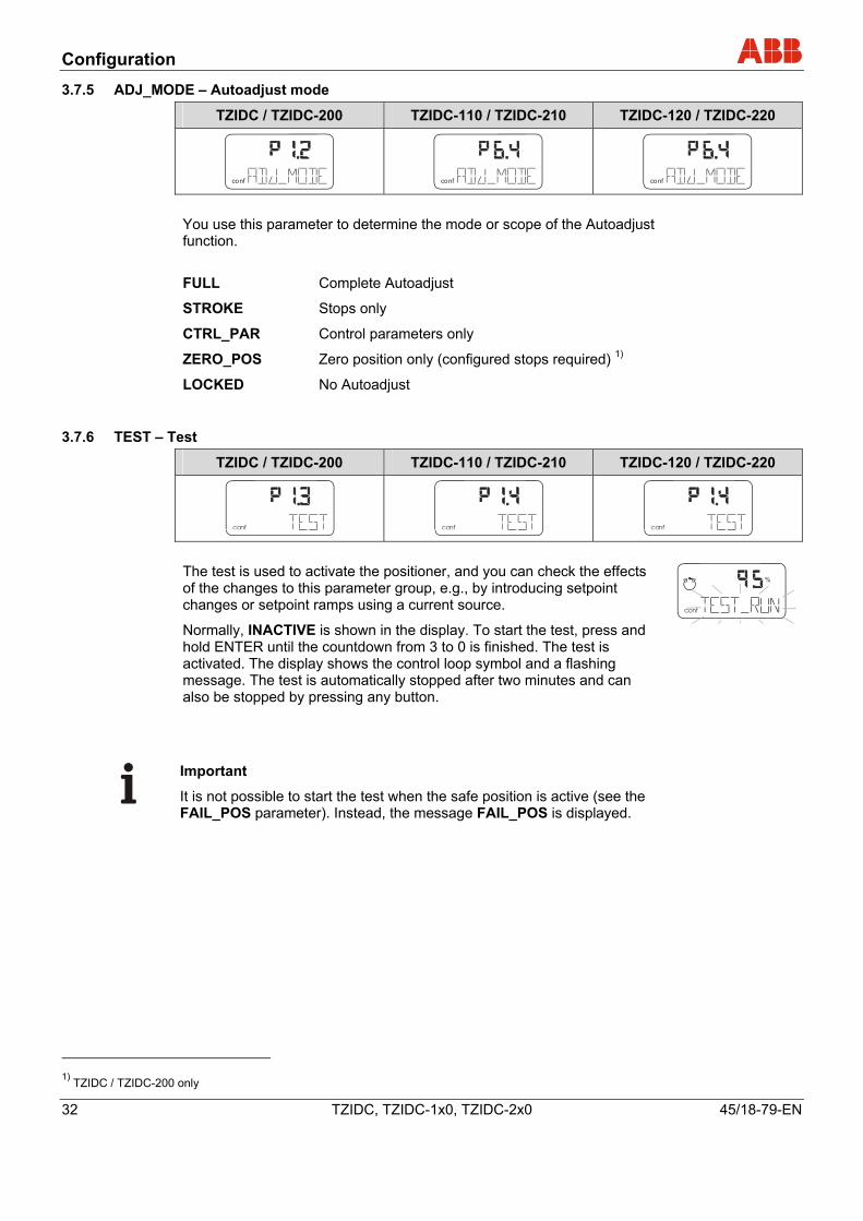
3.7.5 ADJ_MODE – Autoadjust mode
TZIDC / TZIDC-200 TZIDC-110 / TZIDC-210 TZIDC-120 / TZIDC-220
conf
mA%
C°
conf
mA%
C°
conf
mA%
C°
You use this parameter to determine the mode or scope of the Autoadjust function.
FULL Complete Autoadjust
STROKE Stops only
CTRL_PAR Control parameters only
ZERO_POS Zero position only (configured stops required) 1)
LOCKED No Autoadjust
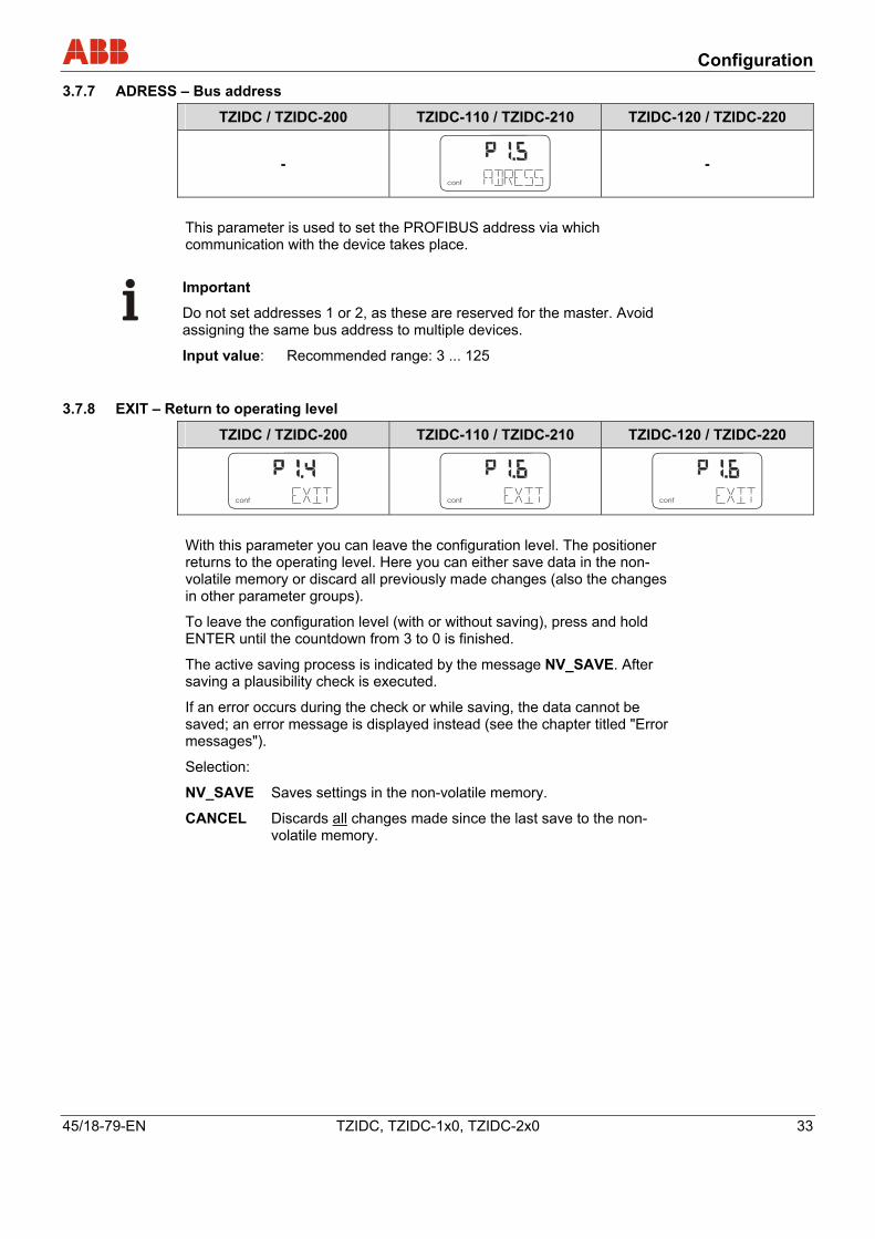
3.7.6 TEST – Test
TZIDC / TZIDC-200 TZIDC-110 / TZIDC-210 TZIDC-120 / TZIDC-220
conf
%
conf
%
conf
%
The test is used to activate the positioner, and you can check the effects of the changes to this parameter group, e.g., by introducing setpoint changes or setpoint ramps using a current source.
Normally, INACTIVE is shown in the display. To start the test, press and hold ENTER until the countdown from 3 to 0 is finished. The test is activated. The display shows the control loop symbol and a flashing message. The test is automatically stopped after two minutes and can also be stopped by pressing any button.
conf
mA
%
C°
Important
It is not possible to start the test when the safe position is active (see the FAIL_POS parameter). Instead, the message FAIL_POS is displayed.
1) TZIDC / TZIDC-200 only
Configuration
45/18-79-EN TZIDC, TZIDC-1x0, TZIDC-2x0 33
3.7.7 ADRESS – Bus address
TZIDC / TZIDC-200 TZIDC-110 / TZIDC-210 TZIDC-120 / TZIDC-220
- conf
%C°
-
This parameter is used to set the PROFIBUS address via which communication with the device takes place.
Important
Do not set addresses 1 or 2, as these are reserved for the master. Avoid assigning the same bus address to multiple devices.
Input value: Recommended range: 3 ... 125
3.7.8 EXIT – Return to operating level
TZIDC / TZIDC-200 TZIDC-110 / TZIDC-210 TZIDC-120 / TZIDC-220
conf
%C°
conf
%C
conf
%C
With this parameter you can leave the configuration level. The positioner returns to the operating level. Here you can either save data in the non-volatile memory or discard all previously made changes (also the changes in other parameter groups).
To leave the configuration level (with or without saving), press and hold ENTER until the countdown from 3 to 0 is finished.
The active saving process is indicated by the message NV_SAVE. After saving a plausibility check is executed.
If an error occurs during the check or while saving, the data cannot be saved; an error message is displayed instead (see the chapter titled "Error messages").
Selection:
NV_SAVE Saves settings in the non-volatile memory.
CANCEL Discards all changes made since the last save to the non-volatile memory.
Configuration
34 TZIDC, TZIDC-1x0, TZIDC-2x0 45/18-79-EN
3.8 Parameter group 2: Setpoint
conf
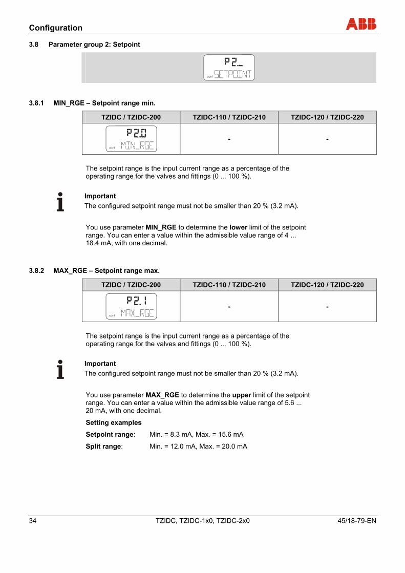
3.8.1 MIN_RGE – Setpoint range min.
TZIDC / TZIDC-200 TZIDC-110 / TZIDC-210 TZIDC-120 / TZIDC-220
conf - -
The setpoint range is the input current range as a percentage of the operating range for the valves and fittings (0 ... 100 %).
Important The configured setpoint range must not be smaller than 20 % (3.2 mA).
You use parameter MIN_RGE to determine the lower limit of the setpoint range. You can enter a value within the admissible value range of 4 ... 18.4 mA, with one decimal.
3.8.2 MAX_RGE – Setpoint range max.
TZIDC / TZIDC-200 TZIDC-110 / TZIDC-210 TZIDC-120 / TZIDC-220
conf
mA%
C°
- -
The setpoint range is the input current range as a percentage of the operating range for the valves and fittings (0 ... 100 %).
Important The configured setpoint range must not be smaller than 20 % (3.2 mA).
You use parameter MAX_RGE to determine the upper limit of the setpoint range. You can enter a value within the admissible value range of 5.6 ... 20 mA, with one decimal.
Setting examples
Setpoint range: Min. = 8.3 mA, Max. = 15.6 mA
Split range: Min. = 12.0 mA, Max. = 20.0 mA
Configuration
45/18-79-EN TZIDC, TZIDC-1x0, TZIDC-2x0 35
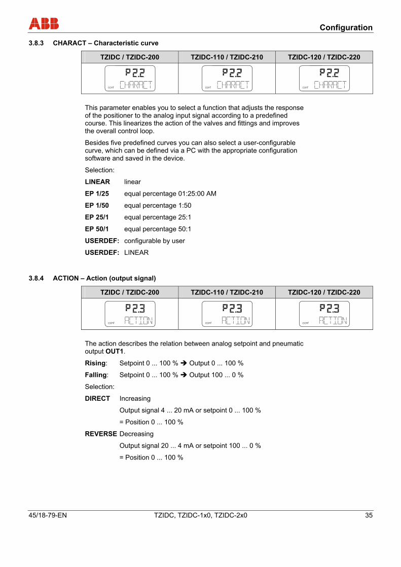
3.8.3 CHARACT – Characteristic curve
TZIDC / TZIDC-200 TZIDC-110 / TZIDC-210 TZIDC-120 / TZIDC-220
conf
mA%
C°
conf
mA%
C°
conf
mA%
C°
This parameter enables you to select a function that adjusts the response of the positioner to the analog input signal according to a predefined course. This linearizes the action of the valves and fittings and improves the overall control loop.
Besides five predefined curves you can also select a user-configurable curve, which can be defined via a PC with the appropriate configuration software and saved in the device.
Selection:
LINEAR linear
EP 1/25 equal percentage 01:25:00 AM
EP 1/50 equal percentage 1:50
EP 25/1 equal percentage 25:1
EP 50/1 equal percentage 50:1
USERDEF: configurable by user
USERDEF: LINEAR
3.8.4 ACTION – Action (output signal)
TZIDC / TZIDC-200 TZIDC-110 / TZIDC-210 TZIDC-120 / TZIDC-220
conf
mA
%
C°
conf
mA
%
C°
conf
mA
%
C°
The action describes the relation between analog setpoint and pneumatic output OUT1.
Rising: Setpoint 0 ... 100 % Output 0 ... 100 %
Falling: Setpoint 0 ... 100 % Output 100 ... 0 %
Selection:
DIRECT Increasing
Output signal 4 ... 20 mA or setpoint 0 ... 100 %
= Position 0 ... 100 %
REVERSE Decreasing
Output signal 20 ... 4 mA or setpoint 100 ... 0 %
= Position 0 ... 100 %
Configuration
36 TZIDC, TZIDC-1x0, TZIDC-2x0 45/18-79-EN
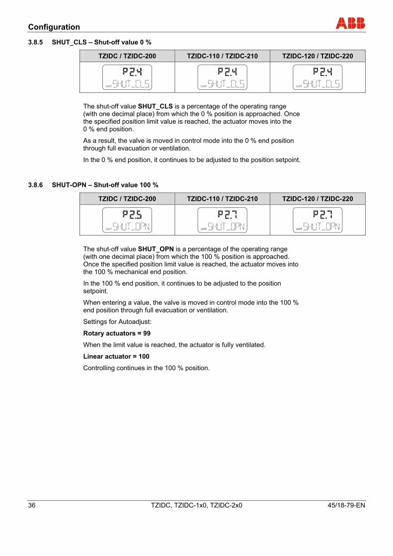
3.8.5 SHUT_CLS – Shut-off value 0 %
TZIDC / TZIDC-200 TZIDC-110 / TZIDC-210 TZIDC-120 / TZIDC-220
conf conf conf The shut-off value SHUT_CLS is a percentage of the operating range (with one decimal place) from which the 0 % position is approached. Once the specified position limit value is reached, the actuator moves into the 0 % end position.
As a result, the valve is moved in control mode into the 0 % end position through full evacuation or ventilation.
In the 0 % end position, it continues to be adjusted to the position setpoint.
3.8.6 SHUT-OPN – Shut-off value 100 %
TZIDC / TZIDC-200 TZIDC-110 / TZIDC-210 TZIDC-120 / TZIDC-220
conf conf conf The shut-off value SHUT_OPN is a percentage of the operating range (with one decimal place) from which the 100 % position is approached. Once the specified position limit value is reached, the actuator moves into the 100 % mechanical end position.
In the 100 % end position, it continues to be adjusted to the position setpoint.
When entering a value, the valve is moved in control mode into the 100 % end position through full evacuation or ventilation.
Settings for Autoadjust:
Rotary actuators = 99
When the limit value is reached, the actuator is fully ventilated.
Linear actuator = 100
Controlling continues in the 100 % position.
Configuration
45/18-79-EN TZIDC, TZIDC-1x0, TZIDC-2x0 37
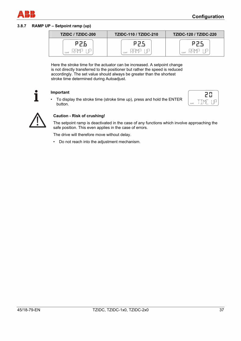
3.8.7 RAMP UP – Setpoint ramp (up)
TZIDC / TZIDC-200 TZIDC-110 / TZIDC-210 TZIDC-120 / TZIDC-220
conf
mA%
C°
conf
mA%
C°
conf
mA%
C°
Here the stroke time for the actuator can be increased. A setpoint change is not directly transferred to the positioner but rather the speed is reduced accordingly. The set value should always be greater than the shortest stroke time determined during Autoadjust.
Important
• To display the stroke time (stroke time up), press and hold the ENTER button. conf
mA%
C
Caution - Risk of crushing!
The setpoint ramp is deactivated in the case of any functions which involve approaching the safe position. This even applies in the case of errors.
The drive will therefore move without delay.
• Do not reach into the adjustment mechanism.
Configuration
38 TZIDC, TZIDC-1x0, TZIDC-2x0 45/18-79-EN
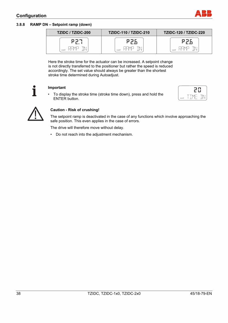
3.8.8 RAMP DN – Setpoint ramp (down)
TZIDC / TZIDC-200 TZIDC-110 / TZIDC-210 TZIDC-120 / TZIDC-220
conf
mA%
C
conf
mA%
C
conf
mA%
C
Here the stroke time for the actuator can be increased. A setpoint change is not directly transferred to the positioner but rather the speed is reduced accordingly. The set value should always be greater than the shortest stroke time determined during Autoadjust.
Important
• To display the stroke time (stroke time down), press and hold the ENTER button. conf
mA%
C
Caution - Risk of crushing!
The setpoint ramp is deactivated in the case of any functions which involve approaching the safe position. This even applies in the case of errors.
The drive will therefore move without delay.
• Do not reach into the adjustment mechanism.
Configuration
45/18-79-EN TZIDC, TZIDC-1x0, TZIDC-2x0 39
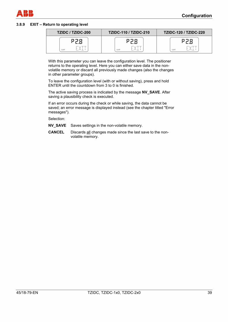
3.8.9 EXIT – Return to operating level
TZIDC / TZIDC-200 TZIDC-110 / TZIDC-210 TZIDC-120 / TZIDC-220
conf
mA
%
C°
conf
mA
%
C°
conf
mA
%
C°
With this parameter you can leave the configuration level. The positioner returns to the operating level. Here you can either save data in the non-volatile memory or discard all previously made changes (also the changes in other parameter groups).
To leave the configuration level (with or without saving), press and hold ENTER until the countdown from 3 to 0 is finished.
The active saving process is indicated by the message NV_SAVE. After saving a plausibility check is executed.
If an error occurs during the check or while saving, the data cannot be saved; an error message is displayed instead (see the chapter titled "Error messages").
Selection:
NV_SAVE Saves settings in the non-volatile memory.
CANCEL Discards all changes made since the last save to the non-volatile memory.
Configuration
40 TZIDC, TZIDC-1x0, TZIDC-2x0 45/18-79-EN
3.9 Parameter group 3: Operating range
conf
3.9.1 MIN_RGE – Operating range min.
TZIDC / TZIDC-200 TZIDC-110 / TZIDC-210 TZIDC-120 / TZIDC-220
conf
mA%
C°
conf
mA%
C°
conf
mA%
C°
The operating range can be configured to be smaller than the maximum mechanical operating range.
The setpoint range always refers to the configured operating range. You use this parameter to determine the lower limit of the operating range.
Caution - Risk
This function is only effective in control mode. If auxiliary power fails (electric or pneumatic) and in manual mode, the mechanical stops are reached.
Important
The operating range must be greater than 10% of the sensor range.
Important The display of the positioner in operating modes 1.0 through 1.2 always refers to the configured operating range and indicates the position in %.
Configuration
45/18-79-EN TZIDC, TZIDC-1x0, TZIDC-2x0 41
3.9.2 MAX_RGE – Operating range max.
TZIDC / TZIDC-200 TZIDC-110 / TZIDC-210 TZIDC-120 / TZIDC-220
conf conf conf The operating range can be configured to be smaller than the maximum mechanical operating range.
The setpoint range always refers to the configured operating range. You use this parameter to determine the upper limit of the operating range.
Caution - Risk
This function is only effective in control mode. If auxiliary power fails (electric or pneumatic) and in manual mode, the mechanical stops are reached.
Important The operating range must be greater than 10% of the sensor range.
Important The display of the positioner in operating modes 1.0 through 1.2 always refers to the configured operating range and indicates the position in %.
Configuration
42 TZIDC, TZIDC-1x0, TZIDC-2x0 45/18-79-EN
3.9.3 ZERO_POS– Zero position
TZIDC / TZIDC-200 TZIDC-110 / TZIDC-210 TZIDC-120 / TZIDC-220
conf
mA%
C°
conf
mA%
C°
conf
mA%
C°
With this parameter you can assign the zero position of the display to the zero position of the valves and fittings. It also allows you to select the direction of rotation of the sensor shaft (looking at the open housing).
Important
Normally, the zero position is determined automatically and saved during standard Autoadjust.
Linear actuators "counterclockwise"
Rotary actuators "clockwise" Selection:
CLOCKW Stop reached turning clockwise
CTCLOCKW Stop reached turning counterclockwise
3.9.4 EXIT – Return to operating level
TZIDC / TZIDC-200 TZIDC-110 / TZIDC-210 TZIDC-120 / TZIDC-220
conf
mA%
C°
conf
mA%
C°
conf
mA%
C°
With this parameter you can leave the configuration level. The positioner returns to the operating level. Here you can either save data in the non-volatile memory or discard all previously made changes (also the changes in other parameter groups).
To leave the configuration level (with or without saving), press and hold ENTER until the countdown from 3 to 0 is finished.
The active saving process is indicated by the message NV_SAVE. After saving a plausibility check is executed.
If an error occurs during the check or while saving, the data cannot be saved; an error message is displayed instead (see the chapter titled "Error messages").
Selection:
NV_SAVE Saves settings in the non-volatile memory.
CANCEL Discards all changes made since the last save to the non-volatile memory.
Configuration
45/18-79-EN TZIDC, TZIDC-1x0, TZIDC-2x0 43
3.10 Parameter group 4: Messages
conf
3.10.1 TIME_OUT – Dead band time limit
TZIDC / TZIDC-200 TZIDC-110 / TZIDC-210 TZIDC-120 / TZIDC-220
- -
With this parameter you enter the monitoring time until reaching the setpoint.
When the tolerance band is exceeded, the monitoring time is started. If the tolerance band within the predefined time is again not reached by the new position setpoint, an alarm is triggered.
(Parameter TIME_OUT in parameter group 5 must be activated.)
Caution - Risk With active shutdown function there is no alarm message.
After reaching the setpoint the alarm is automatically reset.
conf
mA%
C
Important The stroke time to be monitored should be 1.5 to 2x greater than the shortest stroke time selected during Autoadjust. Press and hold the ENTER button to display the stroke time. By pressing ENTER briefly again you can toggle between UP stroke time and DOWN stroke time.
Configuration
44 TZIDC, TZIDC-1x0, TZIDC-2x0 45/18-79-EN
3.10.2 POS_SW1 – Switching point SW1
TZIDC / TZIDC-200 TZIDC-110 / TZIDC-210 TZIDC-120 / TZIDC-220
conf
mA%
C°
- -
With this parameter you can define the switching point SW1 as a percentage of the operating range.
If the position is above or below SW1, the corresponding signal output on the plug-in module is activated (see also parameter group DIG_OUT).
Important Changing the operating range also changes the positions of the switching points with respect to the position of the valves and fittings.
3.10.3 POS_SW2 – Switching point SW2
TZIDC / TZIDC-200 TZIDC-110 / TZIDC-210 TZIDC-120 / TZIDC-220
conf
mA%
C°
- -
With this parameter you can define the switching point SW2 as a percentage of the operating range.
If the position is above or below SW2, the corresponding signal output on the plug-in module is activated (see also parameter group DIG_OUT).
Important Changing the operating range also changes the positions of the switching points with respect to the position of the valves and fittings.
3.10.4 SW1_ACTV – Active direction SW1
TZIDC / TZIDC-200 TZIDC-110 / TZIDC-210 TZIDC-120 / TZIDC-220
conf
mA%
C°
- -
With this parameter you define whether a message is to be triggered for exceeding or falling below switching point SW1.
EXCEED Message when exceeding switching point SW1.
FALL_BEL Message when falling below switching point SW1.
Configuration
45/18-79-EN TZIDC, TZIDC-1x0, TZIDC-2x0 45
3.10.5 SW2_ACTV – Active direction SW2
TZIDC / TZIDC-200 TZIDC-110 / TZIDC-210 TZIDC-120 / TZIDC-220
conf
mA%
C°
- -
With this parameter you define whether a message is to be triggered for exceeding or falling below switching point SW2.
EXCEED Message when exceeding switching point SW2.
FALL_BEL Message when falling below switching point SW2.
3.10.6 EXIT – Return to operating level
TZIDC / TZIDC-200 TZIDC-110 / TZIDC-210 TZIDC-120 / TZIDC-220
conf
mA%
C°
- -
With this parameter you can leave the configuration level. The positioner returns to the operating level. Here you can either save data in the non-volatile memory or discard all previously made changes (also the changes in other parameter groups).
To leave the configuration level (with or without saving), press and hold ENTER until the countdown from 3 to 0 is finished.
The active saving process is indicated by the message NV_SAVE. After saving a plausibility check is executed.
If an error occurs during the check or while saving, the data cannot be saved; an error message is displayed instead (see the chapter titled "Error messages").
Selection:
NV_SAVE Saves settings in the non-volatile memory.
CANCEL Discards all changes made since the last save to the non-volatile memory.
Configuration
46 TZIDC, TZIDC-1x0, TZIDC-2x0 45/18-79-EN
3.11 Parameter group 5: Alarms
conf
mA%
C°
Important Active alarms are signaled at the digital output and using the "Analog feedback" option.
3.11.1 LEAKAGE – Leakage at actuator
TZIDC / TZIDC-200 TZIDC-110 / TZIDC-210 TZIDC-120 / TZIDC-220
conf
mA%
C°
- -
If the monitoring function detects leakage at the actuator, a message is issued via alarm output on the mainboard.
ACTIVE Monitoring active
INACTIVE Monitoring inactive
3.11.2 SP_RGE – Setpoint monitoring
TZIDC / TZIDC-200 TZIDC-110 / TZIDC-210 TZIDC-120 / TZIDC-220
conf
mA%
C°
- -
With this parameter you can determine that a corresponding alarm is signaled via the digital output when falling below or exceeding the setpoint range (< 3.8 mA or above 20.5 mA). ACTIVE Setpoint monitoring active
INACTIVE Setpoint monitoring inactive
Configuration
45/18-79-EN TZIDC, TZIDC-1x0, TZIDC-2x0 47
3.11.3 SENS_RGE – Operating range exceeded
TZIDC / TZIDC-200 TZIDC-110 / TZIDC-210 TZIDC-120 / TZIDC-220
conf
mA%
C°
- -
With this parameter you can determine that an alarm is signaled via the digital output when the configured operating range is exceeded by 4%. (Position < -4 % or > +104 %).
This may indicate improperly adjusted mounting or mechanical wear in a limit stop. ACTIVE Alarm is activated
INACTIVE Alarm is not activated
3.11.4 CTRLER – Controller inactive
TZIDC / TZIDC-200 TZIDC-110 / TZIDC-210 TZIDC-120 / TZIDC-220
conf
mA%
C°
- -
You can use this parameter to specify signaling of an alarm via a digital output if the positioner is not active, i.e., if the control mode is interrupted by another operating mode or by configuration.
Important
For details on the states that can result in a message, refer to the chapter titled "Alarm messages". ACTIVE Alarm is activated
INACTIVE Alarm is not activated
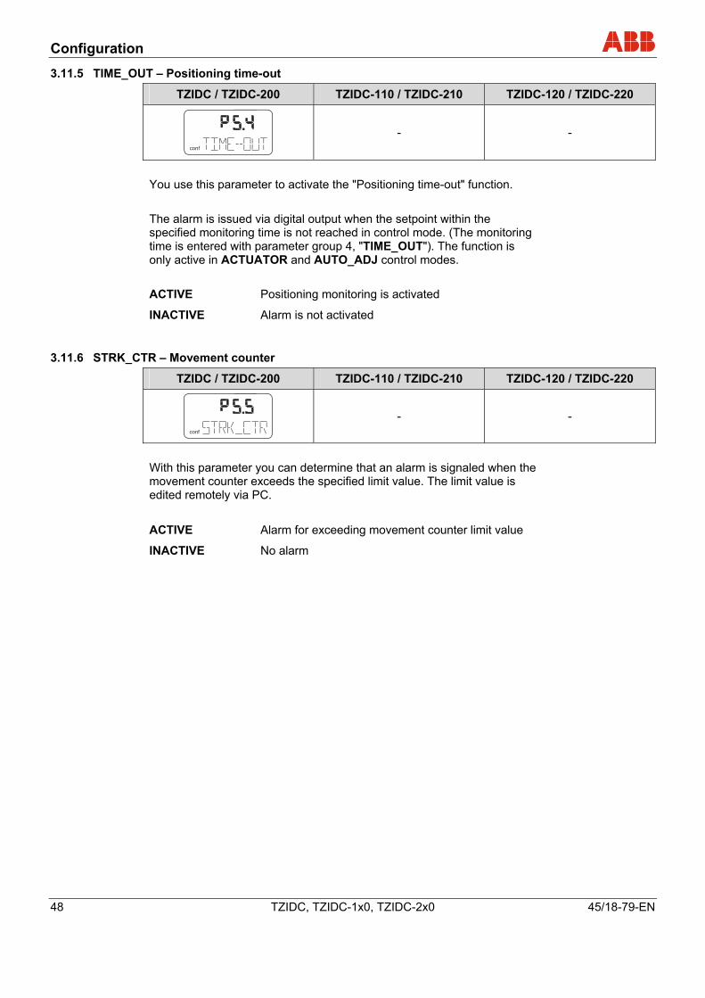
Configuration
48 TZIDC, TZIDC-1x0, TZIDC-2x0 45/18-79-EN
3.11.5 TIME_OUT – Positioning time-out
TZIDC / TZIDC-200 TZIDC-110 / TZIDC-210 TZIDC-120 / TZIDC-220
conf
mA%
C°
- -
You use this parameter to activate the "Positioning time-out" function. The alarm is issued via digital output when the setpoint within the specified monitoring time is not reached in control mode. (The monitoring time is entered with parameter group 4, "TIME_OUT"). The function is only active in ACTUATOR and AUTO_ADJ control modes. ACTIVE Positioning monitoring is activated
INACTIVE Alarm is not activated
3.11.6 STRK_CTR – Movement counter
TZIDC / TZIDC-200 TZIDC-110 / TZIDC-210 TZIDC-120 / TZIDC-220
conf
mA%
C°
- -
With this parameter you can determine that an alarm is signaled when the movement counter exceeds the specified limit value. The limit value is edited remotely via PC. ACTIVE Alarm for exceeding movement counter limit value
INACTIVE No alarm
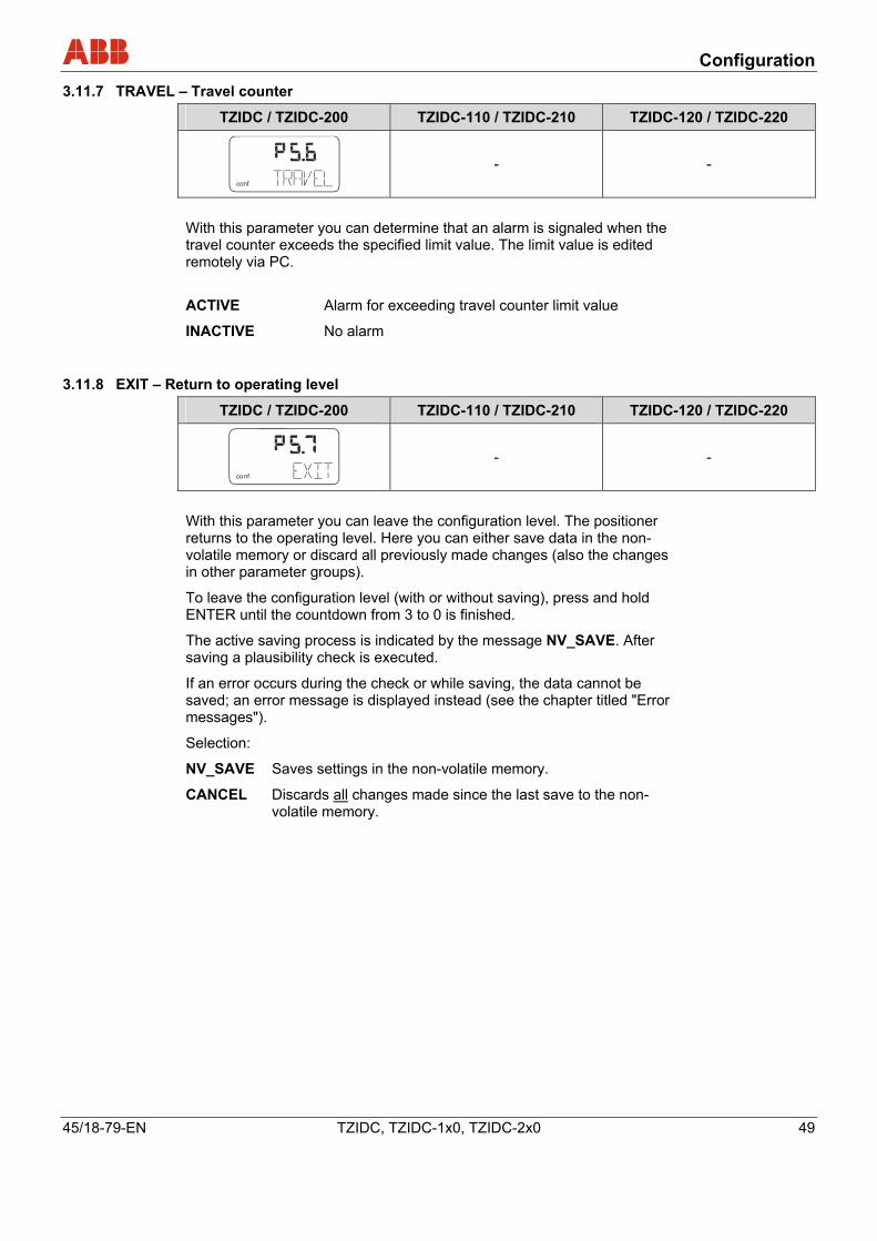
Configuration
45/18-79-EN TZIDC, TZIDC-1x0, TZIDC-2x0 49
3.11.7 TRAVEL – Travel counter
TZIDC / TZIDC-200 TZIDC-110 / TZIDC-210 TZIDC-120 / TZIDC-220
conf
mA%
C°
- -
With this parameter you can determine that an alarm is signaled when the travel counter exceeds the specified limit value. The limit value is edited remotely via PC. ACTIVE Alarm for exceeding travel counter limit value
INACTIVE No alarm
3.11.8 EXIT – Return to operating level
TZIDC / TZIDC-200 TZIDC-110 / TZIDC-210 TZIDC-120 / TZIDC-220
conf
mA%
C°
- -
With this parameter you can leave the configuration level. The positioner returns to the operating level. Here you can either save data in the non-volatile memory or discard all previously made changes (also the changes in other parameter groups).
To leave the configuration level (with or without saving), press and hold ENTER until the countdown from 3 to 0 is finished.
The active saving process is indicated by the message NV_SAVE. After saving a plausibility check is executed.
If an error occurs during the check or while saving, the data cannot be saved; an error message is displayed instead (see the chapter titled "Error messages").
Selection:
NV_SAVE Saves settings in the non-volatile memory.
CANCEL Discards all changes made since the last save to the non-volatile memory.
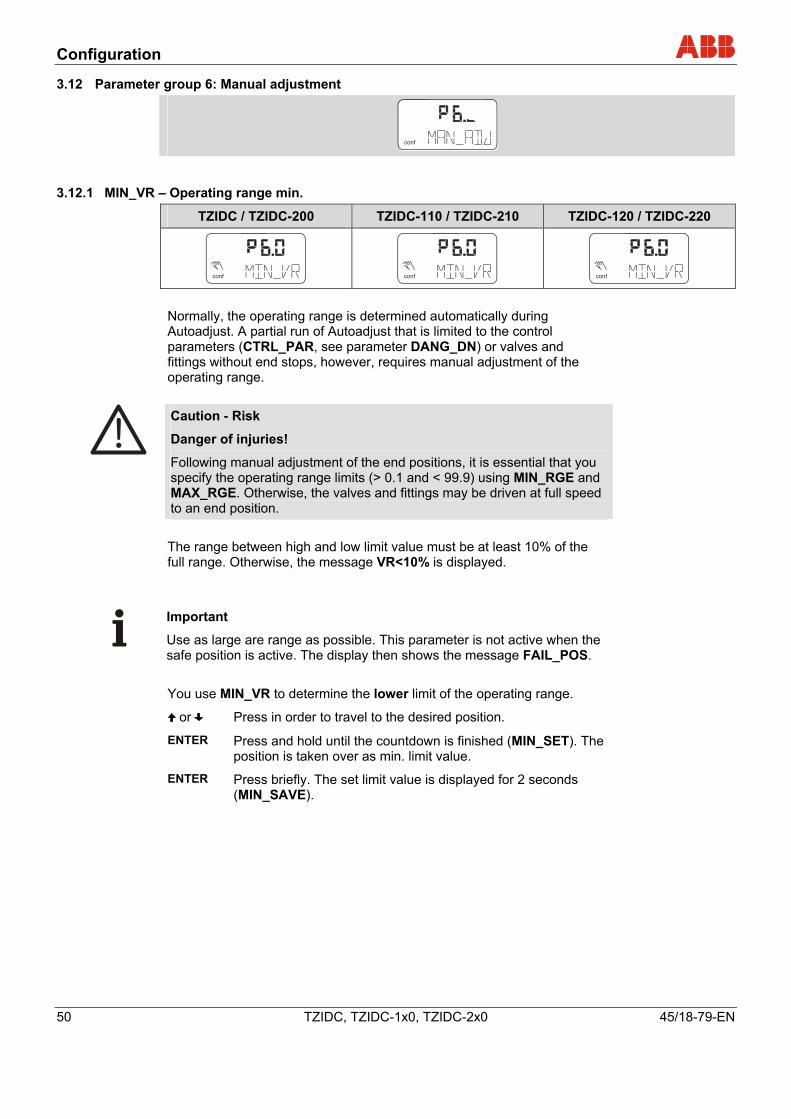
Configuration
50 TZIDC, TZIDC-1x0, TZIDC-2x0 45/18-79-EN
3.12 Parameter group 6: Manual adjustment
conf
3.12.1 MIN_VR – Operating range min.
TZIDC / TZIDC-200 TZIDC-110 / TZIDC-210 TZIDC-120 / TZIDC-220
conf
mA%
C°
conf
mA%
C°
conf
mA%
C°
Normally, the operating range is determined automatically during Autoadjust. A partial run of Autoadjust that is limited to the control parameters (CTRL_PAR, see parameter DANG_DN) or valves and fittings without end stops, however, requires manual adjustment of the operating range.
Caution - Risk
Danger of injuries!
Following manual adjustment of the end positions, it is essential that you specify the operating range limits (> 0.1 and < 99.9) using MIN_RGE and MAX_RGE. Otherwise, the valves and fittings may be driven at full speed to an end position. The range between high and low limit value must be at least 10% of the full range. Otherwise, the message VR<10% is displayed.
Important
Use as large are range as possible. This parameter is not active when the safe position is active. The display then shows the message FAIL_POS. You use MIN_VR to determine the lower limit of the operating range.
or Press in order to travel to the desired position.
ENTER Press and hold until the countdown is finished (MIN_SET). The position is taken over as min. limit value.
ENTER Press briefly. The set limit value is displayed for 2 seconds (MIN_SAVE).
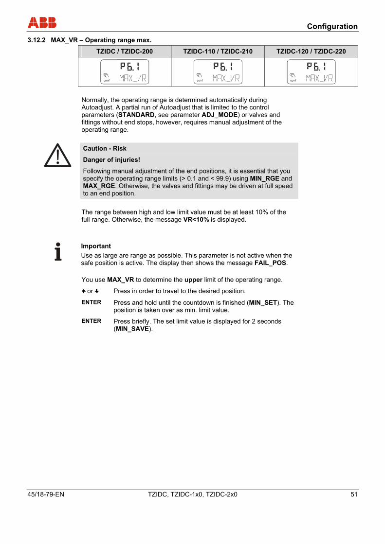
Configuration
45/18-79-EN TZIDC, TZIDC-1x0, TZIDC-2x0 51
3.12.2 MAX_VR – Operating range max.
TZIDC / TZIDC-200 TZIDC-110 / TZIDC-210 TZIDC-120 / TZIDC-220
conf
mA%
C°
conf
mA%
C°
conf
mA%
C°
Normally, the operating range is determined automatically during Autoadjust. A partial run of Autoadjust that is limited to the control parameters (STANDARD, see parameter ADJ_MODE) or valves and fittings without end stops, however, requires manual adjustment of the operating range.
Caution - Risk
Danger of injuries!
Following manual adjustment of the end positions, it is essential that you specify the operating range limits (> 0.1 and < 99.9) using MIN_RGE and MAX_RGE. Otherwise, the valves and fittings may be driven at full speed to an end position. The range between high and low limit value must be at least 10% of the full range. Otherwise, the message VR<10% is displayed.
Important Use as large are range as possible. This parameter is not active when the safe position is active. The display then shows the message FAIL_POS. You use MAX_VR to determine the upper limit of the operating range.
or Press in order to travel to the desired position.
ENTER Press and hold until the countdown is finished (MIN_SET). The position is taken over as min. limit value.
ENTER Press briefly. The set limit value is displayed for 2 seconds (MIN_SAVE).
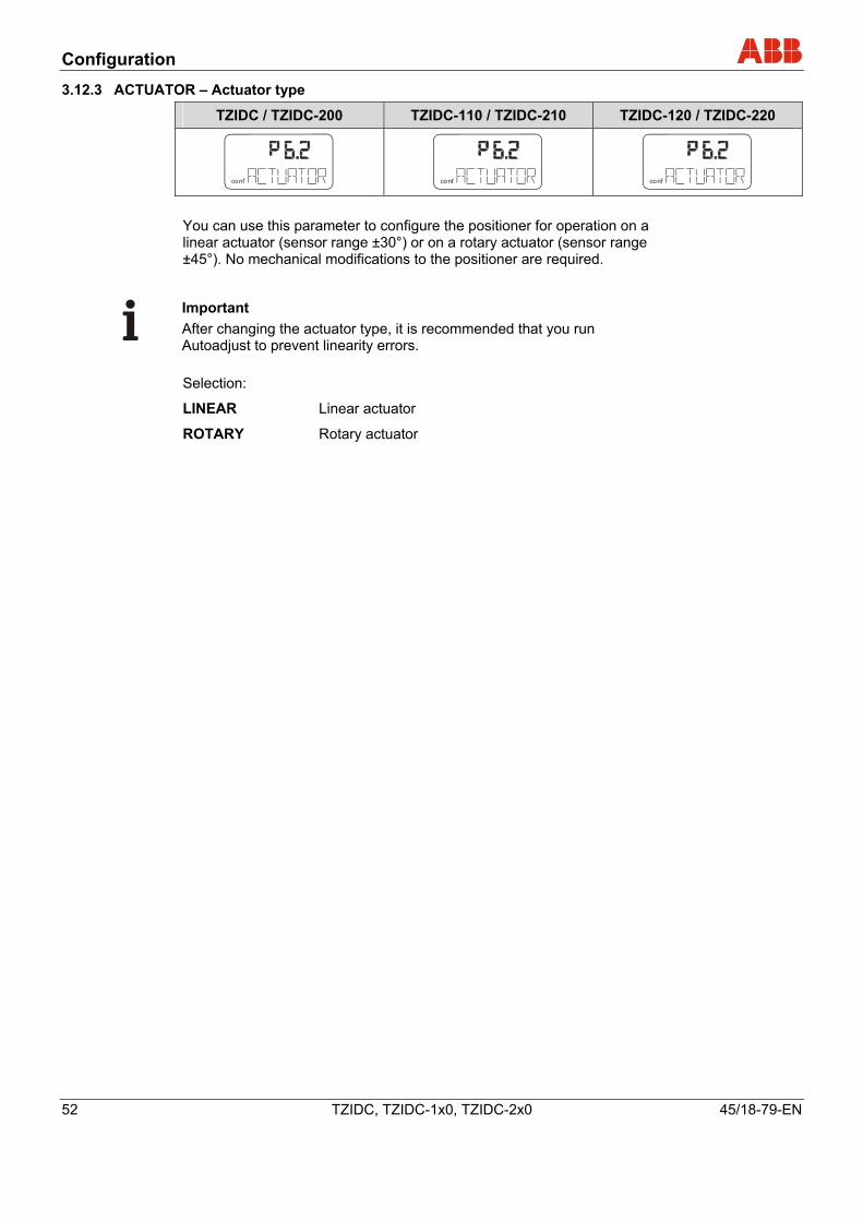
Configuration
52 TZIDC, TZIDC-1x0, TZIDC-2x0 45/18-79-EN
3.12.3 ACTUATOR – Actuator type
TZIDC / TZIDC-200 TZIDC-110 / TZIDC-210 TZIDC-120 / TZIDC-220
conf conf conf You can use this parameter to configure the positioner for operation on a linear actuator (sensor range ±30°) or on a rotary actuator (sensor range ±45°). No mechanical modifications to the positioner are required.
Important After changing the actuator type, it is recommended that you run Autoadjust to prevent linearity errors. Selection:
LINEAR Linear actuator
ROTARY Rotary actuator
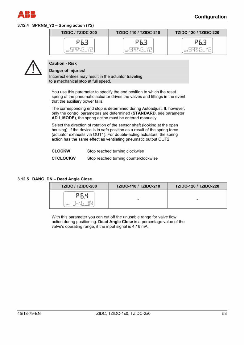
Configuration
45/18-79-EN TZIDC, TZIDC-1x0, TZIDC-2x0 53
3.12.4 SPRNG_Y2 – Spring action (Y2)
TZIDC / TZIDC-200 TZIDC-110 / TZIDC-210 TZIDC-120 / TZIDC-220
conf
mA%
C°
conf
mA%
C°
conf
mA%
C°
Caution - Risk
Danger of injuries! Incorrect entries may result in the actuator traveling to a mechanical stop at full speed.
You use this parameter to specify the end position to which the reset spring of the pneumatic actuator drives the valves and fittings in the event that the auxiliary power fails.
The corresponding end stop is determined during Autoadjust. If, however, only the control parameters are determined (STANDARD, see parameter ADJ_MODE), the spring action must be entered manually.
Select the direction of rotation of the sensor shaft (looking at the open housing), if the device is in safe position as a result of the spring force (actuator exhausts via OUT1). For double-acting actuators, the spring action has the same effect as ventilating pneumatic output OUT2. CLOCKW Stop reached turning clockwise
CTCLOCKW Stop reached turning counterclockwise
3.12.5 DANG_DN – Dead Angle Close
TZIDC / TZIDC-200 TZIDC-110 / TZIDC-210 TZIDC-120 / TZIDC-220
con f
mA%
C°
- -
With this parameter you can cut off the unusable range for valve flow action during positioning. Dead Angle Close is a percentage value of the valve's operating range, if the input signal is 4.16 mA.
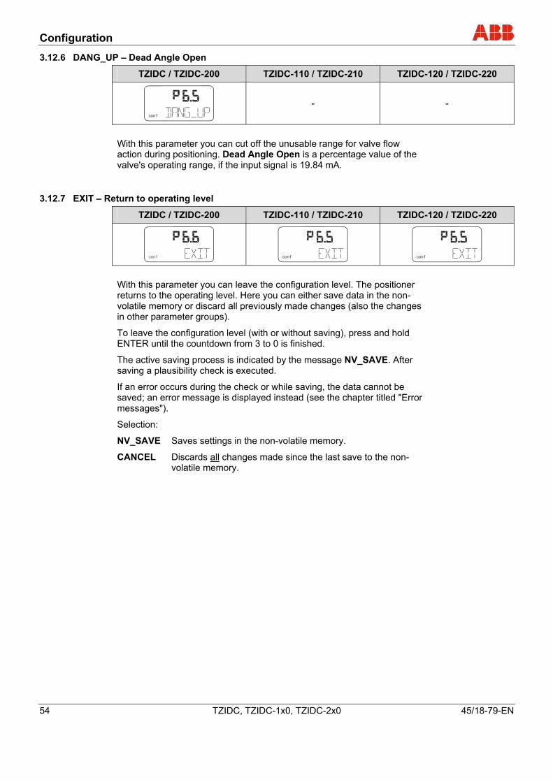
Configuration
54 TZIDC, TZIDC-1x0, TZIDC-2x0 45/18-79-EN
3.12.6 DANG_UP – Dead Angle Open
TZIDC / TZIDC-200 TZIDC-110 / TZIDC-210 TZIDC-120 / TZIDC-220
con f
mA%
C°
- -
With this parameter you can cut off the unusable range for valve flow action during positioning. Dead Angle Open is a percentage value of the valve's operating range, if the input signal is 19.84 mA.
3.12.7 EXIT – Return to operating level
TZIDC / TZIDC-200 TZIDC-110 / TZIDC-210 TZIDC-120 / TZIDC-220
con f
mA%
C°
con f
mA%
C°
con f
mA%
C°
With this parameter you can leave the configuration level. The positioner returns to the operating level. Here you can either save data in the non-volatile memory or discard all previously made changes (also the changes in other parameter groups).
To leave the configuration level (with or without saving), press and hold ENTER until the countdown from 3 to 0 is finished.
The active saving process is indicated by the message NV_SAVE. After saving a plausibility check is executed.
If an error occurs during the check or while saving, the data cannot be saved; an error message is displayed instead (see the chapter titled "Error messages").
Selection:
NV_SAVE Saves settings in the non-volatile memory.
CANCEL Discards all changes made since the last save to the non-volatile memory.
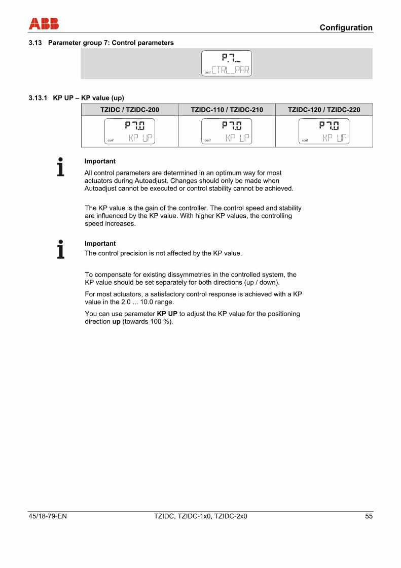
Configuration
45/18-79-EN TZIDC, TZIDC-1x0, TZIDC-2x0 55
3.13 Parameter group 7: Control parameters
conf
3.13.1 KP UP – KP value (up)
TZIDC / TZIDC-200 TZIDC-110 / TZIDC-210 TZIDC-120 / TZIDC-220
conf
mA%
C°
conf
mA%
C°
conf
mA%
C°
Important
All control parameters are determined in an optimum way for most actuators during Autoadjust. Changes should only be made when Autoadjust cannot be executed or control stability cannot be achieved. The KP value is the gain of the controller. The control speed and stability are influenced by the KP value. With higher KP values, the controlling speed increases.
Important The control precision is not affected by the KP value.
To compensate for existing dissymmetries in the controlled system, the KP value should be set separately for both directions (up / down).
For most actuators, a satisfactory control response is achieved with a KP value in the 2.0 ... 10.0 range.
You can use parameter KP UP to adjust the KP value for the positioning direction up (towards 100 %).
Configuration
56 TZIDC, TZIDC-1x0, TZIDC-2x0 45/18-79-EN
3.13.2 KP DN – KP value (down)
TZIDC / TZIDC-200 TZIDC-110 / TZIDC-210 TZIDC-120 / TZIDC-220
conf
mA%
C°
conf
mA%
C°
conf
mA%
C°
Important
All control parameters are determined in an optimum way for most actuators during Autoadjust. Changes should only be made when Autoadjust cannot be executed or control stability cannot be achieved. The KP value is the gain of the controller. The control speed and stability are influenced by the KP value. With higher KP values, the controlling speed increases.
Important
The control precision is not affected by the KP value. To compensate for existing dissymmetries in the controlled system, the KP value should be set separately for both directions (up/down).
For most actuators, a satisfactory control response is achieved with a KP value between 2.0 and 10.0.
You can use parameter KP DN to adjust the KP value for the positioning direction down (towards 0 %).
Configuration
45/18-79-EN TZIDC, TZIDC-1x0, TZIDC-2x0 57
3.13.3 TV UP – TV value (up)
TZIDC / TZIDC-200 TZIDC-110 / TZIDC-210 TZIDC-120 / TZIDC-220
conf
mA%
C°
conf
mA%
C°
conf
mA%
C°
Important
All control parameters are determined in an optimum way for most actuators during Autoadjust. Changes should only be made when Autoadjust cannot be executed or control stability cannot be achieved. The TV value is the derivative time of the controller.
Speed and stability are affected by the TV value in such a way that it counteracts dynamically to the KP value. The speed of the control action decreases for an increasing TV value.
To compensate for existing dissymmetries in the controlled system, the TV value should be set separately for both directions (up/down).
You can use parameter TV UP to adjust the TV value for the positioning direction up (towards 100 %).
3.13.4 TV DN – TV value (down)
TZIDC / TZIDC-200 TZIDC-110 / TZIDC-210 TZIDC-120 / TZIDC-220
conf
mA%
C°
conf
mA%
C°
conf
mA%
C°
Important
All control parameters are determined in an optimum way for most actuators during Autoadjust. Changes should only be made when Autoadjust cannot be executed or control stability cannot be achieved. The TV value is the derivative time of the controller.
Speed and stability are affected by the TV value in such a way that it counteracts dynamically to the KP value. The speed of the control action decreases for an increasing TV value.
To compensate for existing dissymmetries in the controlled system, the TV value should be set separately for both directions (up/down).
You can use parameter TV DN to adjust the TV value for the positioning direction down (towards 0 %).
Configuration
58 TZIDC, TZIDC-1x0, TZIDC-2x0 45/18-79-EN
3.13.5 GOPULSE UP – Go pulse (up)
TZIDC / TZIDC-200 TZIDC-110 / TZIDC-210 TZIDC-120 / TZIDC-220
conf
mA%
C°
conf
mA%
C°
Important
All control parameters are determined in an optimum way for most actuators during Autoadjust. Changes should only be made when Autoadjust cannot be executed or control stability cannot be achieved.
The positioner issues an amplified positioning signal for the defined pulse length and with the actuator not moving, in order to achieve accelerated starting of the actuator. This improves the dynamic, in particular, for small setpoint changes.
To compensate for existing dissymmetries in the controlled system, the go pulse should be set separately for both directions (up/down).
If the actuator consistently overshoots the setpoint, decrease the go pulse. For small and fast actuators, it may be necessary to set the go pulse to 0, even if Autoadjust has determined a higher value.
Important
The value determined by Autoadjust should not be increased, as this may result in overshooting! You can use parameter GOPULSE UP to move the go pulse for adjustment towards 100 %.
Input value: In 20 ms increments
Configuration
45/18-79-EN TZIDC, TZIDC-1x0, TZIDC-2x0 59
3.13.6 GOPULSE DN – Go pulse (down)
TZIDC / TZIDC-200 TZIDC-110 / TZIDC-210 TZIDC-120 / TZIDC-220
conf
mA%
C°
conf
mA%
C°
Important
All control parameters are determined in an optimum way for most actuators during Autoadjust. Changes should only be made when Autoadjust cannot be executed or control stability cannot be achieved.
The positioner issues an amplified positioning signal for the defined pulse length and with the actuator not moving, in order to achieve accelerated starting of the actuator. This improves the dynamic, in particular, for small setpoint changes.
To compensate for existing dissymmetries in the controlled system, the go pulse should be set separately for both directions (up/down).
If the control response consistently overshoots the setpoint, decrease the go pulse. For small and fast actuators, it may be necessary to set the go pulse to 0, even if Autoadjust has determined a higher value.
Important
The value determined by Autoadjust should not be increased, as this may result in overshooting! You can use parameter GOPULSE DN to move the go pulse for adjustment towards 0 %.
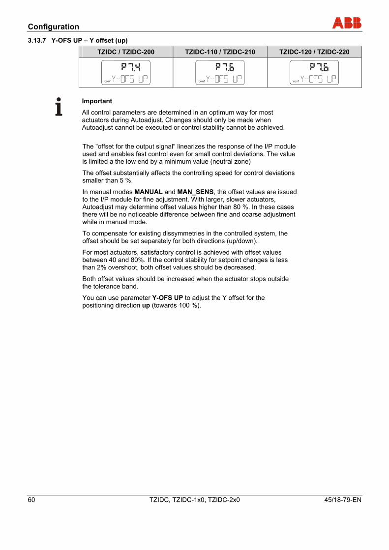
Configuration
60 TZIDC, TZIDC-1x0, TZIDC-2x0 45/18-79-EN
3.13.7 Y-OFS UP – Y offset (up)
TZIDC / TZIDC-200 TZIDC-110 / TZIDC-210 TZIDC-120 / TZIDC-220
conf
mA%
C°
conf
mA%
C°
conf
mA%
C°
Important
All control parameters are determined in an optimum way for most actuators during Autoadjust. Changes should only be made when Autoadjust cannot be executed or control stability cannot be achieved. The "offset for the output signal" linearizes the response of the I/P module used and enables fast control even for small control deviations. The value is limited a the low end by a minimum value (neutral zone)
The offset substantially affects the controlling speed for control deviations smaller than 5 %.
In manual modes MANUAL and MAN_SENS, the offset values are issued to the I/P module for fine adjustment. With larger, slower actuators, Autoadjust may determine offset values higher than 80 %. In these cases there will be no noticeable difference between fine and coarse adjustment while in manual mode.
To compensate for existing dissymmetries in the controlled system, the offset should be set separately for both directions (up/down).
For most actuators, satisfactory control is achieved with offset values between 40 and 80%. If the control stability for setpoint changes is less than 2% overshoot, both offset values should be decreased.
Both offset values should be increased when the actuator stops outside the tolerance band.
You can use parameter Y-OFS UP to adjust the Y offset for the positioning direction up (towards 100 %).
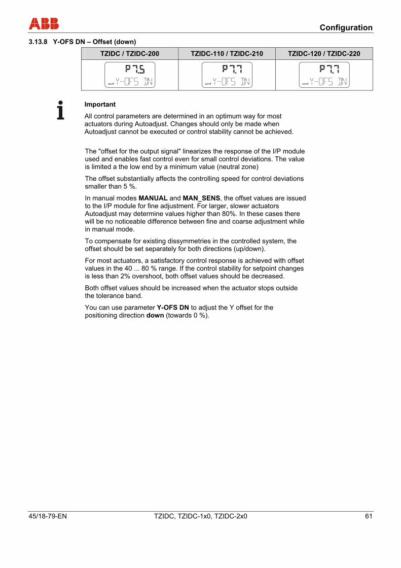
Configuration
45/18-79-EN TZIDC, TZIDC-1x0, TZIDC-2x0 61
3.13.8 Y-OFS DN – Offset (down)
TZIDC / TZIDC-200 TZIDC-110 / TZIDC-210 TZIDC-120 / TZIDC-220
conf
mA%
C°
conf
mA%
C°
conf
mA%
C°
Important
All control parameters are determined in an optimum way for most actuators during Autoadjust. Changes should only be made when Autoadjust cannot be executed or control stability cannot be achieved. The "offset for the output signal" linearizes the response of the I/P module used and enables fast control even for small control deviations. The value is limited a the low end by a minimum value (neutral zone)
The offset substantially affects the controlling speed for control deviations smaller than 5 %.
In manual modes MANUAL and MAN_SENS, the offset values are issued to the I/P module for fine adjustment. For larger, slower actuators Autoadjust may determine values higher than 80%. In these cases there will be no noticeable difference between fine and coarse adjustment while in manual mode.
To compensate for existing dissymmetries in the controlled system, the offset should be set separately for both directions (up/down).
For most actuators, a satisfactory control response is achieved with offset values in the 40 ... 80 % range. If the control stability for setpoint changes is less than 2% overshoot, both offset values should be decreased.
Both offset values should be increased when the actuator stops outside the tolerance band.
You can use parameter Y-OFS DN to adjust the Y offset for the positioning direction down (towards 0 %).
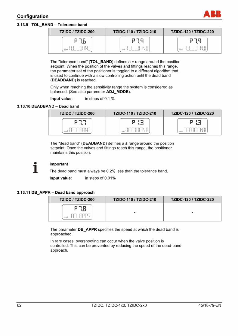
Configuration
62 TZIDC, TZIDC-1x0, TZIDC-2x0 45/18-79-EN
3.13.9 TOL_BAND – Tolerance band
TZIDC / TZIDC-200 TZIDC-110 / TZIDC-210 TZIDC-120 / TZIDC-220
conf
mA%
C°
conf
mA%
C°
conf
mA%
C°
The "tolerance band" (TOL_BAND) defines a ± range around the position setpoint. When the position of the valves and fittings reaches this range, the parameter set of the positioner is toggled to a different algorithm that is used to continue with a slow controlling action until the dead band (DEADBAND) is reached.
Only when reaching the sensitivity range the system is considered as balanced. (See also parameter ADJ_MODE).
Input value: in steps of 0.1 %
3.13.10 DEADBAND – Dead band
TZIDC / TZIDC-200 TZIDC-110 / TZIDC-210 TZIDC-120 / TZIDC-220
conf
mA%
C°
conf
mA%
C°
conf
mA%
C°
The "dead band" (DEADBAND) defines a ± range around the position setpoint. Once the valves and fittings reach this range, the positioner maintains this position.
Important
The dead band must always be 0.2% less than the tolerance band.
Input value: in steps of 0.01%
3.13.11 DB_APPR – Dead band approach
TZIDC / TZIDC-200 TZIDC-110 / TZIDC-210 TZIDC-120 / TZIDC-220
conf
mA%
C°
- -
The parameter DB_APPR specifies the speed at which the dead band is approached.
In rare cases, overshooting can occur when the valve position is controlled. This can be prevented by reducing the speed of the dead-band approach.
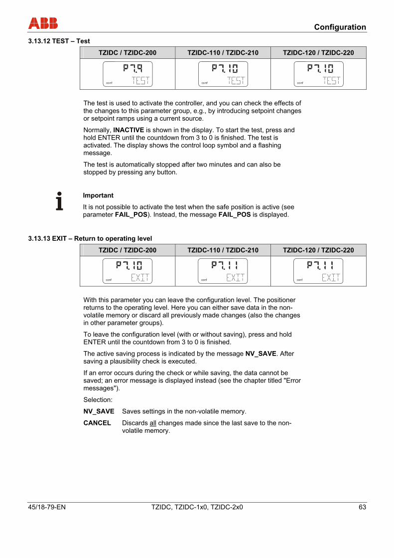
Configuration
45/18-79-EN TZIDC, TZIDC-1x0, TZIDC-2x0 63
3.13.12 TEST – Test
TZIDC / TZIDC-200 TZIDC-110 / TZIDC-210 TZIDC-120 / TZIDC-220
conf
mA%
C°
conf
mA%
C°
conf
mA%
C°
The test is used to activate the controller, and you can check the effects of the changes to this parameter group, e.g., by introducing setpoint changes or setpoint ramps using a current source.
Normally, INACTIVE is shown in the display. To start the test, press and hold ENTER until the countdown from 3 to 0 is finished. The test is activated. The display shows the control loop symbol and a flashing message.
The test is automatically stopped after two minutes and can also be stopped by pressing any button.
Important
It is not possible to activate the test when the safe position is active (see parameter FAIL_POS). Instead, the message FAIL_POS is displayed.
3.13.13 EXIT – Return to operating level
TZIDC / TZIDC-200 TZIDC-110 / TZIDC-210 TZIDC-120 / TZIDC-220
conf
mA
C
conf
mA
C
conf
mA
C
With this parameter you can leave the configuration level. The positioner returns to the operating level. Here you can either save data in the non-volatile memory or discard all previously made changes (also the changes in other parameter groups).
To leave the configuration level (with or without saving), press and hold ENTER until the countdown from 3 to 0 is finished.
The active saving process is indicated by the message NV_SAVE. After saving a plausibility check is executed.
If an error occurs during the check or while saving, the data cannot be saved; an error message is displayed instead (see the chapter titled "Error messages").
Selection:
NV_SAVE Saves settings in the non-volatile memory.
CANCEL Discards all changes made since the last save to the non-volatile memory.
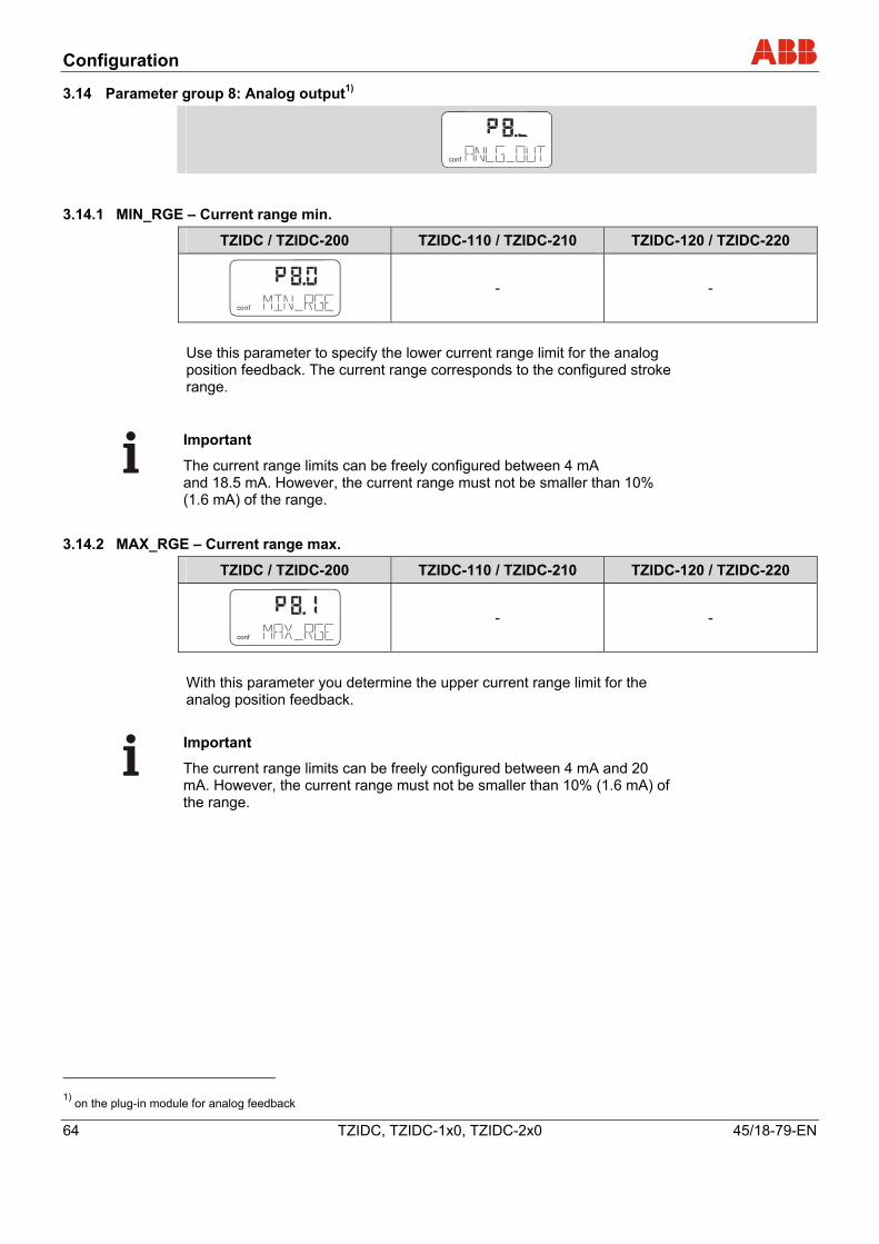
Configuration
64 TZIDC, TZIDC-1x0, TZIDC-2x0 45/18-79-EN
3.14 Parameter group 8: Analog output1)
conf
3.14.1 MIN_RGE – Current range min.
TZIDC / TZIDC-200 TZIDC-110 / TZIDC-210 TZIDC-120 / TZIDC-220
conf - -
Use this parameter to specify the lower current range limit for the analog position feedback. The current range corresponds to the configured stroke range.
Important
The current range limits can be freely configured between 4 mA and 18.5 mA. However, the current range must not be smaller than 10% (1.6 mA) of the range.
3.14.2 MAX_RGE – Current range max.
TZIDC / TZIDC-200 TZIDC-110 / TZIDC-210 TZIDC-120 / TZIDC-220
conf
mA%
C°
- -
With this parameter you determine the upper current range limit for the analog position feedback.
Important
The current range limits can be freely configured between 4 mA and 20 mA. However, the current range must not be smaller than 10% (1.6 mA) of the range.
1) on the plug-in module for analog feedback
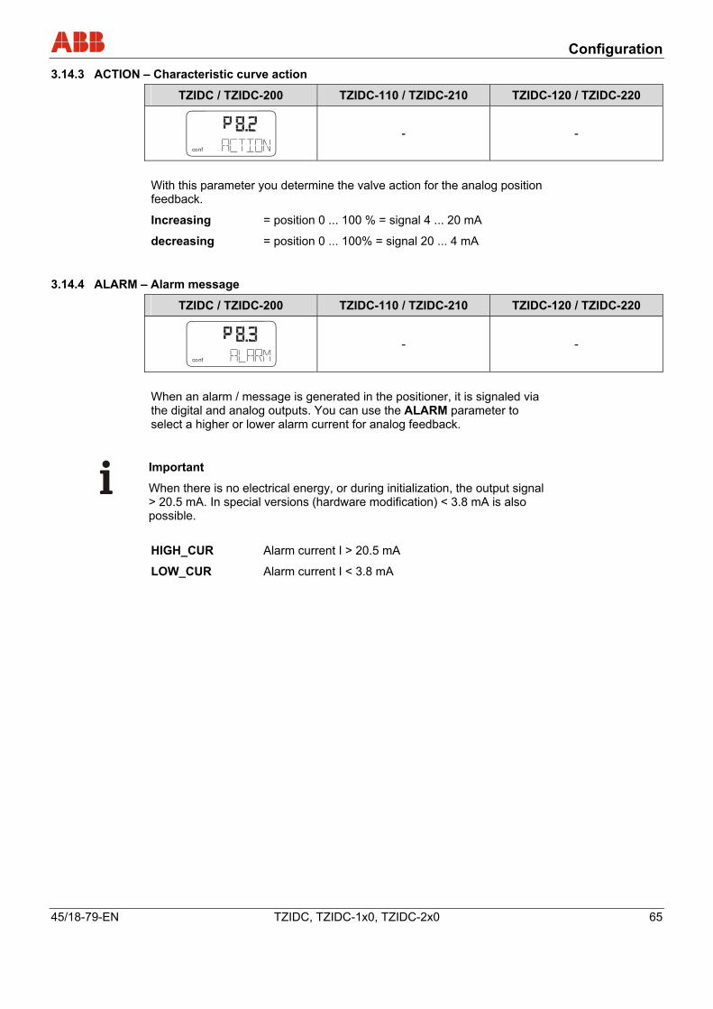
Configuration
45/18-79-EN TZIDC, TZIDC-1x0, TZIDC-2x0 65
3.14.3 ACTION – Characteristic curve action
TZIDC / TZIDC-200 TZIDC-110 / TZIDC-210 TZIDC-120 / TZIDC-220
conf
mA%
C°
- -
With this parameter you determine the valve action for the analog position feedback.
Increasing = position 0 ... 100 % = signal 4 ... 20 mA
decreasing = position 0 ... 100% = signal 20 ... 4 mA
3.14.4 ALARM – Alarm message
TZIDC / TZIDC-200 TZIDC-110 / TZIDC-210 TZIDC-120 / TZIDC-220
conf - -
When an alarm / message is generated in the positioner, it is signaled via the digital and analog outputs. You can use the ALARM parameter to select a higher or lower alarm current for analog feedback.
Important
When there is no electrical energy, or during initialization, the output signal > 20.5 mA. In special versions (hardware modification) < 3.8 mA is also possible. HIGH_CUR Alarm current I > 20.5 mA
LOW_CUR Alarm current I < 3.8 mA
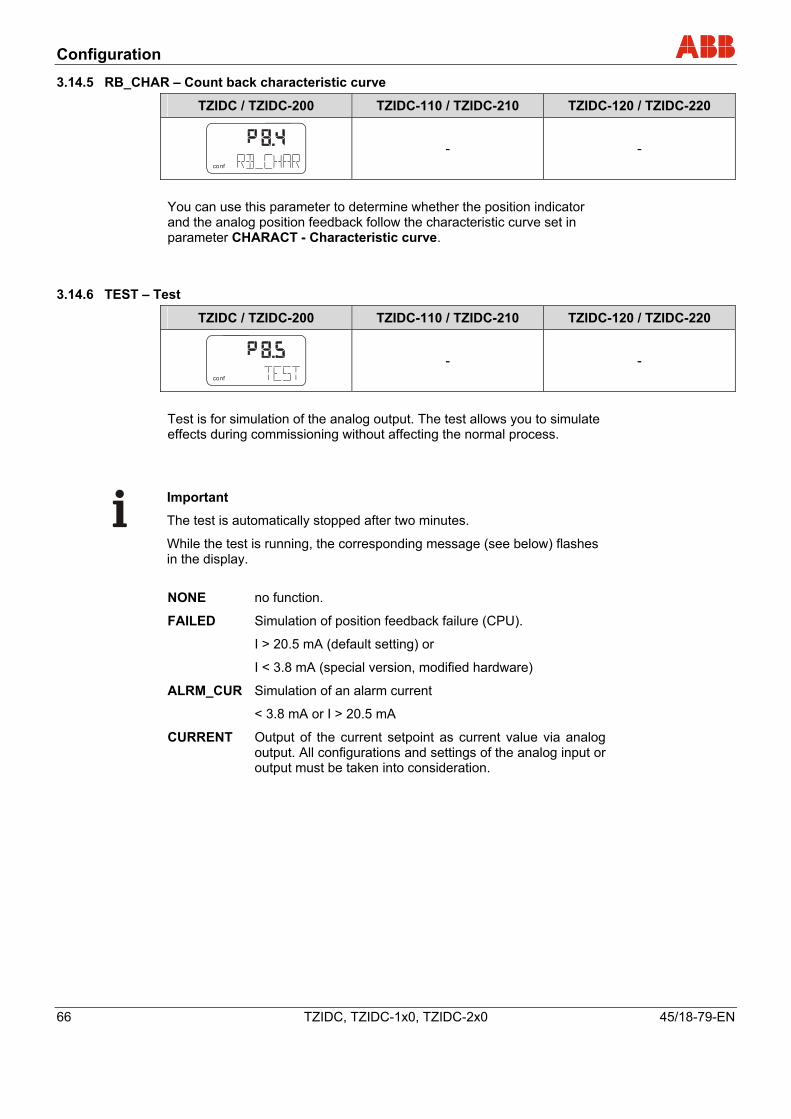
Configuration
66 TZIDC, TZIDC-1x0, TZIDC-2x0 45/18-79-EN
3.14.5 RB_CHAR – Count back characteristic curve
TZIDC / TZIDC-200 TZIDC-110 / TZIDC-210 TZIDC-120 / TZIDC-220
conf
mA%
C°
- -
You can use this parameter to determine whether the position indicator and the analog position feedback follow the characteristic curve set in parameter CHARACT - Characteristic curve.
3.14.6 TEST – Test
TZIDC / TZIDC-200 TZIDC-110 / TZIDC-210 TZIDC-120 / TZIDC-220
conf
mA%
C°
- -
Test is for simulation of the analog output. The test allows you to simulate effects during commissioning without affecting the normal process.
Important
The test is automatically stopped after two minutes.
While the test is running, the corresponding message (see below) flashes in the display. NONE no function.
FAILED Simulation of position feedback failure (CPU).
I > 20.5 mA (default setting) or
I < 3.8 mA (special version, modified hardware)
ALRM_CUR Simulation of an alarm current
< 3.8 mA or I > 20.5 mA
CURRENT Output of the current setpoint as current value via analog output. All configurations and settings of the analog input or output must be taken into consideration.
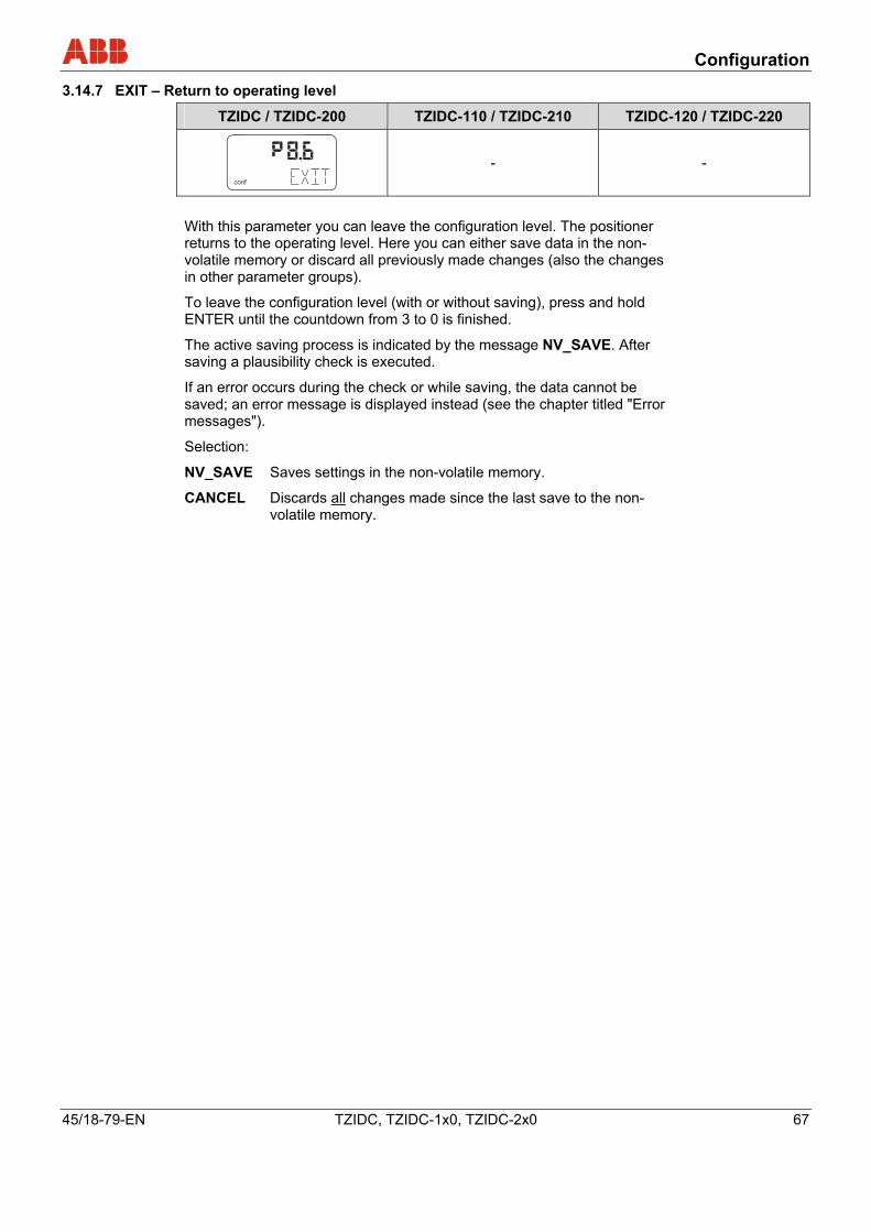
Configuration
45/18-79-EN TZIDC, TZIDC-1x0, TZIDC-2x0 67
3.14.7 EXIT – Return to operating level
TZIDC / TZIDC-200 TZIDC-110 / TZIDC-210 TZIDC-120 / TZIDC-220
conf
mA%
C°
- -
With this parameter you can leave the configuration level. The positioner returns to the operating level. Here you can either save data in the non-volatile memory or discard all previously made changes (also the changes in other parameter groups).
To leave the configuration level (with or without saving), press and hold ENTER until the countdown from 3 to 0 is finished.
The active saving process is indicated by the message NV_SAVE. After saving a plausibility check is executed.
If an error occurs during the check or while saving, the data cannot be saved; an error message is displayed instead (see the chapter titled "Error messages").
Selection:
NV_SAVE Saves settings in the non-volatile memory.
CANCEL Discards all changes made since the last save to the non-volatile memory.
Configuration
68 TZIDC, TZIDC-1x0, TZIDC-2x0 45/18-79-EN
3.15 Parameter group 9: Digital output
conf
mA%
C°
3.15.1 ALRM_LOG – Signal level, digital outputs1)
TZIDC / TZIDC-200 TZIDC-110 / TZIDC-210 TZIDC-120 / TZIDC-220
conf
mA%
C°
- -
You can use this parameter to determine the logic level the alarm output uses to issue the messages.
Selection:
ACTIV_HI active = output current I > 2 mA
ACTIV_LO active = output current I < 1 mA
3.15.2 SW1_LOG – Signal level, SW1
TZIDC / TZIDC-200 TZIDC-110 / TZIDC-210 TZIDC-120 / TZIDC-220
conf
mA%
C°
- -
With this parameter you can determine the active level for switching output SW1*.
Selection:
ACTIV_HI active = output current I > 2 mA
ACTIV_LO active = output current I < 1 mA
1) SW1 and SW2 are on the plug-in module for digital feedback
Configuration
45/18-79-EN TZIDC, TZIDC-1x0, TZIDC-2x0 69
3.15.3 SW2_LOG – Signal level, SW2
TZIDC / TZIDC-200 TZIDC-110 / TZIDC-210 TZIDC-120 / TZIDC-220
conf
mA%
C°
- -
With this parameter you can determine the active level for switching output SW2*.
Selection:
ACTIV_HI active = output current I > 2 mA
ACTIV_LO active = output current I < 1 mA
3.15.4 TEST – Test
TZIDC / TZIDC-200 TZIDC-110 / TZIDC-210 TZIDC-120 / TZIDC-220
conf
mA%
C°
- -
Test is for simulation for the digital output.
Important The test is automatically stopped after two minutes and can be aborted by pressing any button. While the test is running, the corresponding message (see below) flashes in the display. NONE no function
ALRM_ON Alarm is simulated (DO active)
SW1_ON Process for reaching switching point 1 is simulated
(SW1 active)
SW2_ON Process for reaching switching point 2 is simulated
(SW2 active)
ALL_ON Alarm and switching points are simulated (all DOs active)
Configuration
70 TZIDC, TZIDC-1x0, TZIDC-2x0 45/18-79-EN
3.15.5 EXIT – Return to operating level
TZIDC / TZIDC-200 TZIDC-110 / TZIDC-210 TZIDC-120 / TZIDC-220
conf
mA%
C°
- -
With this parameter you can leave the configuration level. The positioner returns to the operating level. Here you can either save data in the non-volatile memory or discard all previously made changes (also the changes in other parameter groups).
To leave the configuration level (with or without saving), press and hold ENTER until the countdown from 3 to 0 is finished.
The active saving process is indicated by the message NV_SAVE. After saving a plausibility check is executed.
If an error occurs during the check or while saving, the data cannot be saved; an error message is displayed instead (see the chapter titled "Error messages").
Selection:
NV_SAVE Saves settings in the non-volatile memory.
CANCEL Discards all changes made since the last save to the non-volatile memory.
Configuration
45/18-79-EN TZIDC, TZIDC-1x0, TZIDC-2x0 71
3.16 Parameter group 10: Digital input
conf
mA%
C°
3.16.1 FUNCTION – Digital input
TZIDC / TZIDC-200 TZIDC-110 / TZIDC-210 TZIDC-120 / TZIDC-220
conf
mA%
C°
- -
For the digital input, one of the following protective functions can be selected via local operation.
• No function (default)
• Move to 0 % position
• Move to 100 % position
• Hold previous position
• Disable local configuration
• Disable local configuration and operation
• Disable all access (local or via PC)
The selected function is activated when the 24 V signal is no longer connected to the digital output (< 10 V DC).
The safety functions POS_0%, POS_100% and POS_HOLD run in the operating level in both types of control modes P1.0 or P1.1. BIN_CTRL is shown in the display.
If a corresponding function is active, a corresponding value is defined internally for the positioner. The actuator is then driven into the end position or position specified under consideration of the setpoint ramp, configured operating range, selected behavior.
After selecting a lock CNF_LOCK, OP_LOCK or ALL_LOCK, the key icon is displayed, indicating that the lock will be activated at the next save.
After saving and without 24V at the digital input, the key is permanently displayed.
Important
The lock CNF_LOCK, OP_LOCK or ALL_LOCK is displayed only if the voltage is connected to the digital input.
Configuration
72 TZIDC, TZIDC-1x0, TZIDC-2x0 45/18-79-EN
CNF_LOCK Restricts local access to the configuration level. However,
local operation on the operating level is possible. The positioner can be configured externally (via LKS / modem and PC).
When the operator tries to activate the configuration level, the text CNF_LOCK is displayed for approx. 5 seconds.
OP_LOCK Fully restricts local operation and configuration. Every time an attempt is made to perform local operating actions, the message OP_LOCK is displayed for approx. 5 seconds..
Important
The positioner can be configured externally (via LKS / modem and PC). ALL_LOCK Restricts local operation (operating level and configuration
level) and external configuration via LKS/modem and PC. With every attempt to perform local operating actions, the text ALL_LOCK is shown for approx. 5 seconds.
3.16.2 EXIT – Return to operating level
TZIDC / TZIDC-200 TZIDC-110 / TZIDC-210 TZIDC-120 / TZIDC-220
conf
mA%
C°
- -
With this parameter you can leave the configuration level. The positioner returns to the operating level. Here you can either save data in the non-volatile memory or discard all previously made changes (also the changes in other parameter groups).
To leave the configuration level (with or without saving), press and hold ENTER until the countdown from 3 to 0 is finished.
The active saving process is indicated by the message NV_SAVE. After saving a plausibility check is executed.
If an error occurs during the check or while saving, the data cannot be saved; an error message is displayed instead (see the chapter titled "Error messages").
Selection:
NV_SAVE Saves settings in the non-volatile memory.
CANCEL Discards all changes made since the last save to the non-volatile memory.
Configuration
45/18-79-EN TZIDC, TZIDC-1x0, TZIDC-2x0 73
3.17 Parameter group 11: Safe position
con f
mA%
C°
3.17.1 FAIL_POS – Safe position
TZIDC / TZIDC-200 TZIDC-110 / TZIDC-210 TZIDC-120 / TZIDC-220
conf
mA%
C°
conf
mA%
C°
conf
mA%
C°
This parameter must be used to activate the safe position prior to loading the factory settings (parameter FACT_SET) or changing the I/P module type (parameter IP-TYP).
Important
After setting parameters FACT_SET and IP-TYP as required, the safe position must be deactivated again manually. The safe position that is activated (i.e., whether the actuator is ventilated or blocked) depends on the I/P module installed. Activating / deactivating the safe position:
Press and hold ENTER until the displayed countdown from 3 to 0 is finished. Then release ENTER.
The safe position is activated or deactivated, respectively.
Configuration
74 TZIDC, TZIDC-1x0, TZIDC-2x0 45/18-79-EN
3.17.2 FACT_SET – Factory setting
TZIDC / TZIDC-200 TZIDC-110 / TZIDC-210 TZIDC-120 / TZIDC-220
conf
mA%
C°
conf
mA%
C°
conf
mA%
C°
You can use this parameter to reset the positioner to the factory setting. This is necessary, e.g., if an already configured positioner has to be installed on a different actuator and subsequently reconfigured.
Caution - Risk
Danger of injuries! For safety reasons, after loading the factory settings you must check whether the I/P module type that is set matches the actual I/P module type present in the device. Otherwise dangerous situations may occur when operating in control mode. It may happen that the actuator is driven at full speed to the end position.
Important
You can only load the factory settings when the actuator is in the safe position (parameter FAIL_POS). Otherwise, the action is inhibited and the message NO_F_POS is indicated in the display.
If you save the settings in the non-volatile memory after loading the factory settings, operating mode 1.3 is automatically activated on the operating level. To load the factory settings:
Press and hold ENTER until the displayed countdown from 3 to 0 is finished.
The positioner is reset to the factory settings. The message COMPLETE is displayed.
Press ENTER to acknowledge the message.
Selection:
FS_LOAD Loads the factory settings
Configuration
45/18-79-EN TZIDC, TZIDC-1x0, TZIDC-2x0 75
3.17.3 IP-TYP – I/P module type
TZIDC / TZIDC-200 TZIDC-110 / TZIDC-210 TZIDC-120 / TZIDC-220
conf conf conf With this parameter the software can be adapted to the installed I/P module. This parameter must be set when installing another I/P module type.
Caution - Risk
Danger of injuries! For safety reasons, after loading the factory settings you must check whether the I/P module type that is set matches the actual I/P module type present in the device. Otherwise dangerous situations may occur when operating in control mode. It may happen that the actuator is driven at full speed to the end position.
Caution - Risk
For safety reasons, after restoring the positioner to the factory settings you must check whether this parameter has been correctly set.
3.17.4 EXIT – Return to operating level
TZIDC / TZIDC-200 TZIDC-110 / TZIDC-210 TZIDC-120 / TZIDC-220
conf
mA%
C°
conf
mA%
C°
conf
mA%
C°
With this parameter you can leave the configuration level. The positioner returns to the operating level. Here you can either save data in the non-volatile memory or discard all previously made changes (also the changes in other parameter groups).
To leave the configuration level (with or without saving), press and hold ENTER until the countdown from 3 to 0 is finished.
The active saving process is indicated by the message NV_SAVE. After saving a plausibility check is executed.
If an error occurs during the check or while saving, the data cannot be saved; an error message is displayed instead (see the chapter titled "Error messages").
Selection:
NV_SAVE Saves settings in the non-volatile memory.
CANCEL Discards all changes made since the last save to the non-volatile memory.
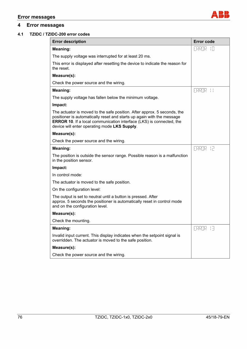
Error messages
76 TZIDC, TZIDC-1x0, TZIDC-2x0 45/18-79-EN
4 Error messages
4.1 TZIDC / TZIDC-200 error codes
Error description Error code
Meaning:
The supply voltage was interrupted for at least 20 ms.
This error is displayed after resetting the device to indicate the reason for the reset.
Measure(s):
Check the power source and the wiring.
Meaning:
The supply voltage has fallen below the minimum voltage.
Impact:
The actuator is moved to the safe position. After approx. 5 seconds, the positioner is automatically reset and starts up again with the message ERROR 10. If a local communication interface (LKS) is connected, the device will enter operating mode LKS Supply.
Measure(s):
Check the power source and the wiring.
Meaning:
The position is outside the sensor range. Possible reason is a malfunction in the position sensor.
Impact:
In control mode:
The actuator is moved to the safe position.
On the configuration level:
The output is set to neutral until a button is pressed. After approx. 5 seconds the positioner is automatically reset in control mode and on the configuration level.
Measure(s):
Check the mounting.
Meaning:
Invalid input current. This display indicates when the setpoint signal is overridden. The actuator is moved to the safe position.
Measure(s):
Check the power source and the wiring.
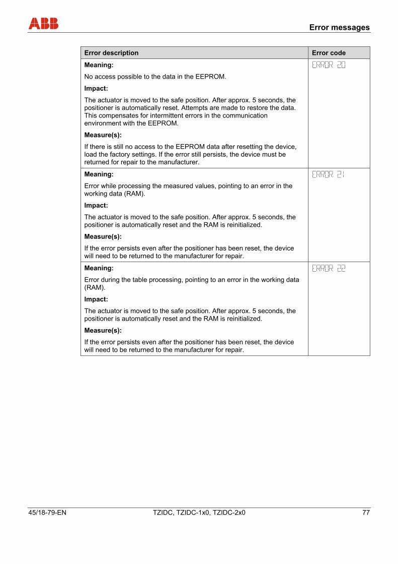
Error messages
45/18-79-EN TZIDC, TZIDC-1x0, TZIDC-2x0 77
Error description Error code
Meaning:
No access possible to the data in the EEPROM.
Impact:
The actuator is moved to the safe position. After approx. 5 seconds, the positioner is automatically reset. Attempts are made to restore the data. This compensates for intermittent errors in the communication environment with the EEPROM.
Measure(s):
If there is still no access to the EEPROM data after resetting the device, load the factory settings. If the error still persists, the device must be returned for repair to the manufacturer.
Meaning:
Error while processing the measured values, pointing to an error in the working data (RAM).
Impact:
The actuator is moved to the safe position. After approx. 5 seconds, the positioner is automatically reset and the RAM is reinitialized.
Measure(s):
If the error persists even after the positioner has been reset, the device will need to be returned to the manufacturer for repair.
Meaning:
Error during the table processing, pointing to an error in the working data (RAM).
Impact:
The actuator is moved to the safe position. After approx. 5 seconds, the positioner is automatically reset and the RAM is reinitialized.
Measure(s):
If the error persists even after the positioner has been reset, the device will need to be returned to the manufacturer for repair.
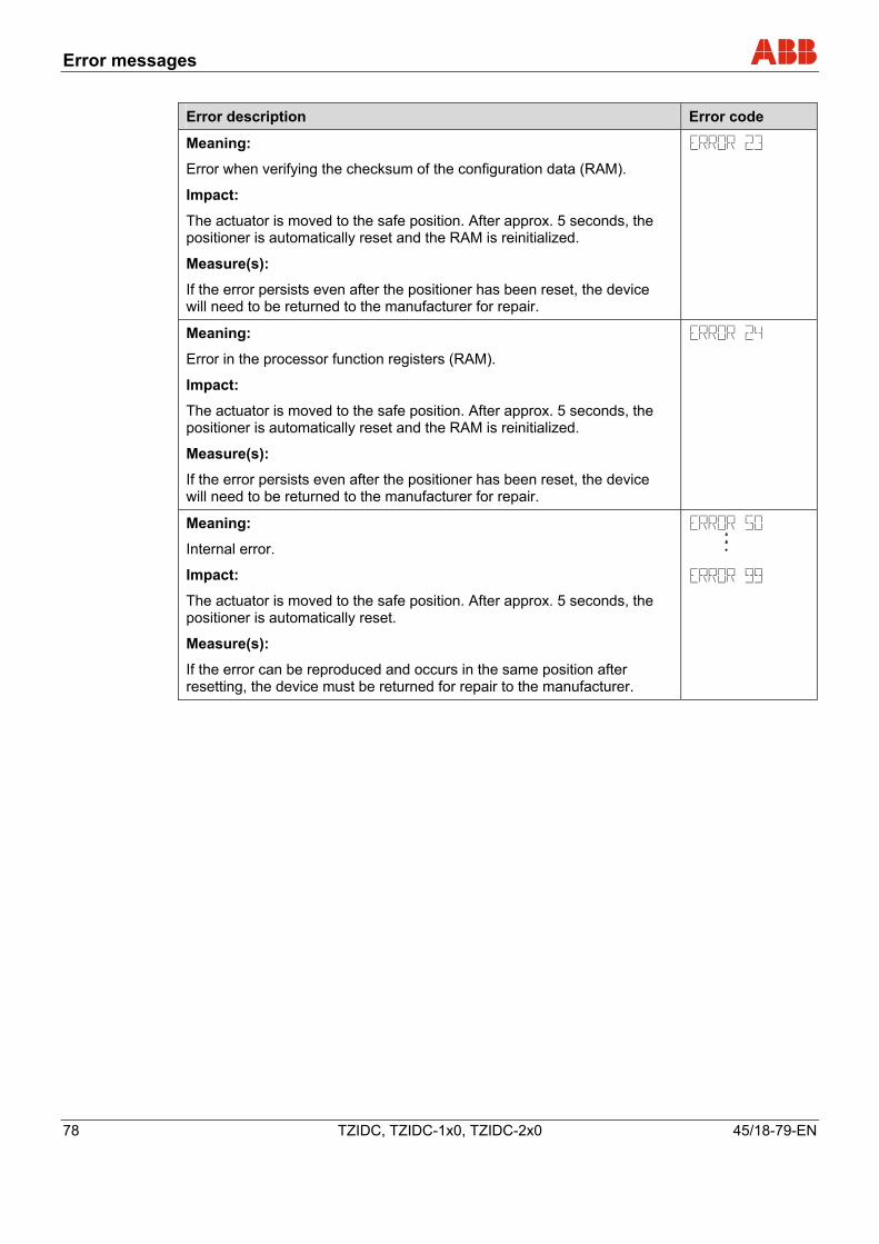
Error messages
78 TZIDC, TZIDC-1x0, TZIDC-2x0 45/18-79-EN
Error description Error code
Meaning:
Error when verifying the checksum of the configuration data (RAM).
Impact:
The actuator is moved to the safe position. After approx. 5 seconds, the positioner is automatically reset and the RAM is reinitialized.
Measure(s):
If the error persists even after the positioner has been reset, the device will need to be returned to the manufacturer for repair.
Meaning:
Error in the processor function registers (RAM).
Impact:
The actuator is moved to the safe position. After approx. 5 seconds, the positioner is automatically reset and the RAM is reinitialized.
Measure(s):
If the error persists even after the positioner has been reset, the device will need to be returned to the manufacturer for repair.
Meaning:
Internal error.
Impact:
The actuator is moved to the safe position. After approx. 5 seconds, the positioner is automatically reset.
Measure(s):
If the error can be reproduced and occurs in the same position after resetting, the device must be returned for repair to the manufacturer.
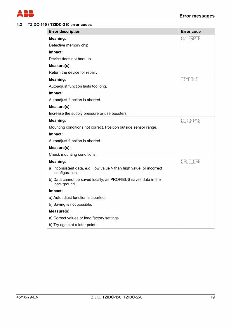
Error messages
45/18-79-EN TZIDC, TZIDC-1x0, TZIDC-2x0 79
4.2 TZIDC-110 / TZIDC-210 error codes
Error description Error code
Meaning:
Defective memory chip
Impact:
Device does not boot up.
Measure(s):
Return the device for repair.
Meaning:
Autoadjust function lasts too long.
Impact:
Autoadjust function is aborted.
Measure(s):
Increase the supply pressure or use boosters.
Meaning:
Mounting conditions not correct. Position outside sensor range.
Impact:
Autoadjust function is aborted.
Measure(s):
Check mounting conditions.
Meaning:
a) Inconsistent data, e.g., low value > than high value, or incorrect configuration.
b) Data cannot be saved locally, as PROFIBUS saves data in the background.
Impact:
a) Autoadjust function is aborted.
b) Saving is not possible.
Measure(s):
a) Correct values or load factory settings.
b) Try again at a later point.
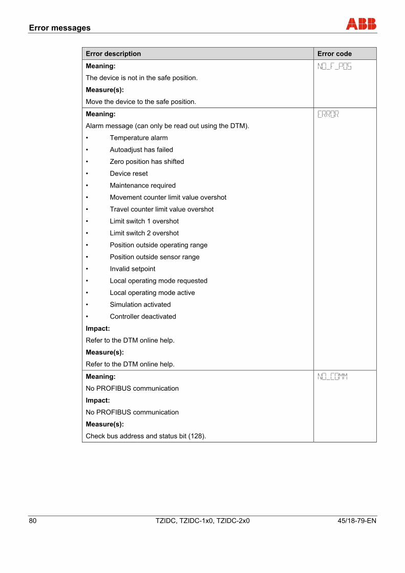
Error messages
80 TZIDC, TZIDC-1x0, TZIDC-2x0 45/18-79-EN
Error description Error code
Meaning:
The device is not in the safe position.
Measure(s):
Move the device to the safe position.
Meaning:
Alarm message (can only be read out using the DTM).
• Temperature alarm
• Autoadjust has failed
• Zero position has shifted
• Device reset
• Maintenance required
• Movement counter limit value overshot
• Travel counter limit value overshot
• Limit switch 1 overshot
• Limit switch 2 overshot
• Position outside operating range
• Position outside sensor range
• Invalid setpoint
• Local operating mode requested
• Local operating mode active
• Simulation activated
• Controller deactivated
Impact:
Refer to the DTM online help.
Measure(s):
Refer to the DTM online help.
Meaning:
No PROFIBUS communication
Impact:
No PROFIBUS communication
Measure(s):
Check bus address and status bit (128).
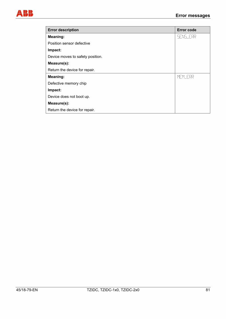
Error messages
45/18-79-EN TZIDC, TZIDC-1x0, TZIDC-2x0 81
Error description Error code
Meaning:
Position sensor defective
Impact:
Device moves to safety position.
Measure(s):
Return the device for repair.
Meaning:
Defective memory chip
Impact:
Device does not boot up.
Measure(s):
Return the device for repair.
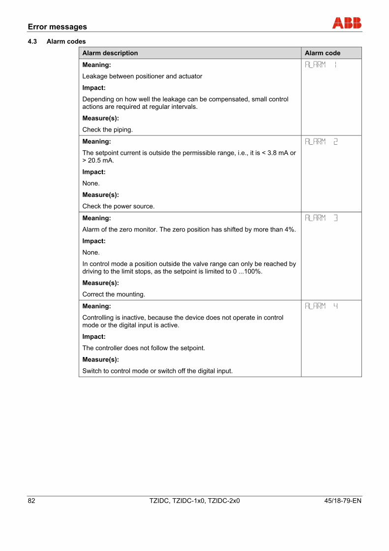
Error messages
82 TZIDC, TZIDC-1x0, TZIDC-2x0 45/18-79-EN
4.3 Alarm codes
Alarm description Alarm code
Meaning:
Leakage between positioner and actuator
Impact:
Depending on how well the leakage can be compensated, small control actions are required at regular intervals.
Measure(s):
Check the piping.
Meaning:
The setpoint current is outside the permissible range, i.e., it is < 3.8 mA or > 20.5 mA.
Impact:
None.
Measure(s):
Check the power source.
Meaning:
Alarm of the zero monitor. The zero position has shifted by more than 4%.
Impact:
None.
In control mode a position outside the valve range can only be reached by driving to the limit stops, as the setpoint is limited to 0 ...100%.
Measure(s):
Correct the mounting.
Meaning:
Controlling is inactive, because the device does not operate in control mode or the digital input is active.
Impact:
The controller does not follow the setpoint.
Measure(s):
Switch to control mode or switch off the digital input.
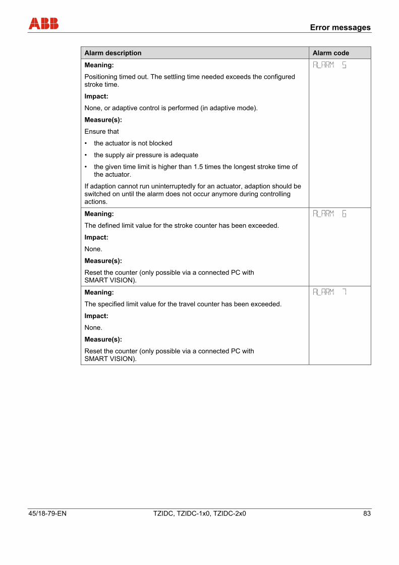
Error messages
45/18-79-EN TZIDC, TZIDC-1x0, TZIDC-2x0 83
Alarm description Alarm code
Meaning:
Positioning timed out. The settling time needed exceeds the configured stroke time.
Impact:
None, or adaptive control is performed (in adaptive mode).
Measure(s):
Ensure that
• the actuator is not blocked
• the supply air pressure is adequate
• the given time limit is higher than 1.5 times the longest stroke time of the actuator.
If adaption cannot run uninterruptedly for an actuator, adaption should be switched on until the alarm does not occur anymore during controlling actions.
Meaning:
The defined limit value for the stroke counter has been exceeded.
Impact:
None.
Measure(s):
Reset the counter (only possible via a connected PC with SMART VISION).
Meaning:
The specified limit value for the travel counter has been exceeded.
Impact:
None.
Measure(s):
Reset the counter (only possible via a connected PC with SMART VISION).
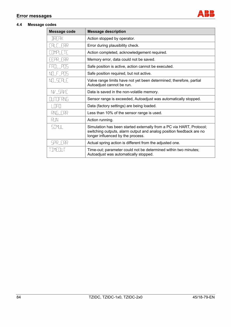
Error messages
84 TZIDC, TZIDC-1x0, TZIDC-2x0 45/18-79-EN
4.4 Message codes
Message code Message description
Action stopped by operator.
Error during plausibility check.
Action completed, acknowledgement required.
Memory error, data could not be saved.
Safe position is active, action cannot be executed.
Safe position required, but not active.
Valve range limits have not yet been determined; therefore, partial Autoadjust cannot be run.
Data is saved in the non-volatile memory.
Sensor range is exceeded, Autoadjust was automatically stopped.
Data (factory settings) are being loaded.
Less than 10% of the sensor range is used.
Action running.
Simulation has been started externally from a PC via HART‚ Protocol; switching outputs, alarm output and analog position feedback are no longer influenced by the process.
Actual spring action is different from the adjusted one.
Time-out; parameter could not be determined within two minutes; Autoadjust was automatically stopped.
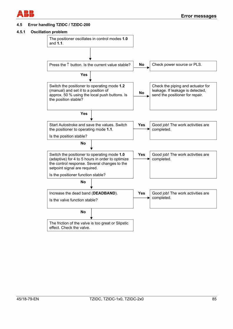
Error messages
45/18-79-EN TZIDC, TZIDC-1x0, TZIDC-2x0 85
4.5 Error handling TZIDC / TZIDC-200
4.5.1 Oscillation problem
The positioner oscillates in control modes 1.0 and 1.1.
Press the ↑ button. Is the current value stable? No Check power source or PLS.
Yes
Switch the positioner to operating mode 1.2 (manual) and set it to a position of approx. 50 % using the local push buttons. Is the position stable?
No
Check the piping and actuator for leakage. If leakage is detected, send the positioner for repair.
Yes
Start Autostroke and save the values. Switch the positioner to operating mode 1.1.
Is the position stable?
Yes Good job! The work activities are completed.
No
Switch the positioner to operating mode 1.0 (adaptive) for 4 to 5 hours in order to optimize the control response. Several changes to the setpoint signal are required.
Is the positioner function stable?
Yes Good job! The work activities are completed.
No
Increase the dead band (DEADBAND).
Is the valve function stable?
Yes Good job! The work activities are completed.
No
The friction of the valve is too great or Slipstic effect. Check the valve.
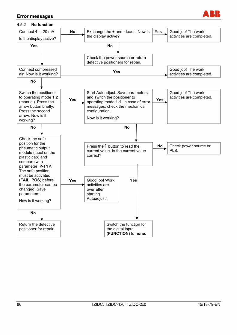
Error messages
86 TZIDC, TZIDC-1x0, TZIDC-2x0 45/18-79-EN
4.5.2 No function
Connect 4 ... 20 mA.
Is the display active?
No Exchange the + and - leads. Now is the display active?
Yes Good job! The work activities are completed.
No Yes
Check the power source or return defective positioners for repair.
Connect compressed air. Now is it working? Yes Good job! The work
activities are completed.
No
Switch the positioner to operating mode 1.2 (manual). Press the arrow button briefly. Press the second arrow. Now is it working?
Yes
Start Autoadjust. Save parameters and switch the positioner to operating mode 1.1. In case of error messages, check the mechanical configuration.
Now is it working?
Yes
Good job! The work activities are completed.
No No
Check power source or PLS.
Press the ↑ button to read the current value. Is the current value correct?
Good job! Work activities are over after starting Autoadjust!
Yes
Check the safe position for the pneumatic output module (label on the plastic cap) and compare with parameter IP-TYP. The safe position must be activated (FAIL_POS) before the parameter can be changed. Save parameters.
Now is it working?
Yes
No
No
Return the defective positioner for repair.
Switch the function for the digital input (FUNCTION) to none.
Appendix
45/18-79-EN TZIDC, TZIDC-1x0, TZIDC-2x0 87
5 Appendix
5.1 Additional documents
• Data Sheet TZIDC (10/18-0.22)
• Data Sheet TZIDC-110 (10/18-0.23)
• Data Sheet TZIDC-120 (10/18-0.24)
• Data Sheet TZIDC-200 (10/18-0.32)
• Data Sheet TZIDC-210 (10/18-0.33)
• Data Sheet TZIDC-220 (10/18-0.34)
• Operating Instructions TZIDC / TZIDC-110 / TZIDC-120 (42/18-84)
• Operating Instructions TZIDC-200 / TZIDC-210 / TZIDC-220 (42/18-85)
• Commissioning Instruction TZIDC, TZIDC-110, TZIDC-120 (CI/TZIDC/110/120)
• Commissioning Instruction TZIDC-200, TZIDC-210, TZIDC-220 (CI/TZIDC-200/210/220)
Appendix
88 TZIDC, TZIDC-1x0, TZIDC-2x0 45/18-79-EN
A
ACTION – Action (output signal) .............................35
ACTION – Characteristic curve action.....................65
ACTUATOR – Actuator type....................................52
ACTUATOR – Actuator type....................................28
Additional documents ..............................................87
ADJ_MODE – Autoadjust mode ..............................32
ADRESS – Bus address ..........................................33
ALARM – Alarm message .......................................65
Alarm codes .............................................................82
ALRM_LOG – Signal level, digital outputs ..............68
Appendix ..................................................................87
AUTO_ADJ – Autoadjust .........................................29
C
CHARACT – Characteristic curve............................35
Configuration............................................................21
CTRLER – Controller inactive..................................47
D
DANG_DN – Dead Angle Close ..............................53
DANG_UP – Dead Angle Open...............................54
DB_APPR – Dead band approach ..........................62
DEADBAND – Dead band .................................31, 62
Displays and operating elements.............................11
E
Error handling TZIDC / TZIDC-200..........................85
Error messages........................................................76
EXIT – Return to operating level.... 33, 39, 42, 45, 49, 54, 63, 67, 70, 72, 75
Explosion protection ..................................................9
F
FACT_SET – Factory setting...................................74
FAIL_POS – Safe position.......................................73
FUNCTION – Digital input .......................................71
Functions on the configuration level ........................14
Functions on the operating level..............................13
G
General information .................................................21
General information and notes for the reader............7
GOPULSE DN – Go pulse (down)...........................59
GOPULSE UP – Go pulse (up)................................58
I
Inhibiting operation...................................................20
Intended use ..............................................................7
IP-TYP – I/P module type ........................................75
K
KP DN – KP value (down) .......................................56
KP UP – KP value (up) ............................................55
L
LEAKAGE – Leakage at actuator ............................46
Local operation ........................................................10
M
MAX_RGE – Current range max. ............................64
MAX_RGE – Operating range max. ........................41
MAX_RGE – Setpoint range max. ...........................34
MAX_VR – Operating range max. ...........................51
Message codes........................................................84
MIN_RGE – Current range min. ..............................64
MIN_RGE – Operating range min............................40
MIN_RGE – Setpoint range min. .............................34
MIN_VR – Operating range min. .............................50
N
No function...............................................................86
Note symbols .............................................................8
O
Operating mode 1.0
Adaptive control....................................................17
Operating mode 1.1
Fixed control.........................................................18
Operating mode 1.2
Manual adjustment within the stroke range .........19
Operating mode 1.3
Manual adjustment within the sensor range ........19
Operating modes .....................................................17
Operation on the operating level..............................16
Oscillation problem ..................................................85
P
Parameter group 1
Standard...............................................................28
Parameter group 10
Digital input...........................................................71
Appendix
45/18-79-EN TZIDC, TZIDC-1x0, TZIDC-2x0 89
Parameter group 11
Safe position.........................................................73
Parameter group 2
Setpoint ................................................................34
Parameter group 3
Operating range ...................................................40
Parameter group 4
Messages.............................................................43
Parameter group 5
Alarms ..................................................................46
Parameter group 6
Manual adjustment...............................................50
Parameter group 7
Control parameters ..............................................55
Parameter group 8
Analog output .......................................................64
Parameter group 9
Digital output ........................................................68
Parameter overview (figure) ..............................26, 27
Parameter overview (table)................................23, 25
Plates and symbols....................................................8
POS_SW1 – Switching point SW1 ..........................44
POS_SW2 – Switching point SW2 ..........................44
R
RAMP DN – Setpoint ramp (down)..........................38
RAMP UP – Setpoint ramp (up)...............................37
RB_CHAR – Count back characteristic curve .........66
Repairs, alterations, and enhancements ...................7
S
Safety.........................................................................7
SENS_RGE – Operating range exceeded ..............47
SHUT_CLS – Shut-off value 0 %.............................36
SHUT-OPN – Shut-off value 100 %.........................36
SP_RGE – Setpoint monitoring ...............................46
SPRNG_Y2 – Spring action (Y2).............................53
STRK_CTR – Movement counter ............................48
SW1_ACTV – Active direction SW1 ........................44
SW1_LOG – Signal level, SW1 ...............................68
SW2_ACTV – Active direction SW2 ........................45
SW2_LOG – Signal level, SW2 ...............................69
T
Target groups and qualifications................................9
TEST – Test.......................................... 32, 63, 66, 69
TIME_OUT – Dead band time limit..........................43
TIME_OUT – Positioning time-out ...........................48
TOL_BAND – Tolerance band...........................31, 62
TRAVEL – Travel counter........................................49
TV DN – TV value (down)........................................57
TV UP – TV value (up).............................................57
TZIDC / TZIDC-200 error codes ..............................76
TZIDC-110 / TZIDC-210 error codes.......................79
Y
Y-OFS DN – Offset (down) ......................................61
Y-OFS UP – Y offset (up) ........................................60
Z
ZERO_POS – Zero position ....................................42
n
ABB has Sales & Customer Support expertise in over 100 countries worldwide. www.abb.com/instrumentation
The Company’s policy is one of continuous product improvement and the right is reserved to modify the
information contained herein without notice.
Printed in the Fed. Rep. of Germany (10.2009)
© ABB 2009
3KXE341001R4501
45/1
8-79
-EN
R
ev. C
ABB Limited Salterbeck Trading Estate Workington, Cumbria CA14 5DS UK Tel: +44 (0)1946 830 611 Fax: +44 (0)1946 832 661
ABB Inc. 125 E. County Line Road Warminster, PA 18974 USA Tel: +1 215 674 6000 Fax: +1 215 674 7183
ABB Automation Products GmbH Schillerstr. 72 32425 Minden Germany Tel: +49 551 905-534 Fax: +49 551 905-555 [email protected]


