EI416/BR100Hall Ticket Number:
IV/IV B.Tech (Regular/Supplementary) DEGREE EXAMINATION
October, 2016 Electronics & Instrumentation Engineering Seventh Semester Automation TechnologyTime: Three Hours Maximum: 60MarksAnswer Question no. 1 Compulsorily (1x12 =12 Marks)Answer ONE question from each unit (4x12 =48 Marks)1. Answer the following 12x1=12Marks
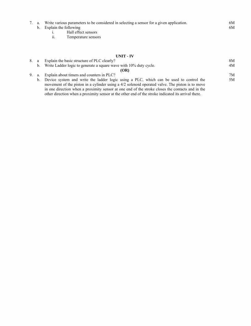
a. What is the difference between gauge pressure and absolute pressure?b. What is the function of pressure regulator?c. 1 psi equal to how many kPa?d. How do you represent the symbol for shuttle valve in hydraulic/pneumatic circuits?e. Write the symbol for pilot operated check valve?f. Define stroke length?g. What is meterout speed control?h. Define hysteresis property of a sensor? i. Define the smart sensor?j. Define nonlinearity error?k. Write any two advantages of PLC in industry?l. Write the ladder logic for the following digital logic operation BAABY +
UNIT - I2. a. Define the following terms
i. Forceii. Poweriii. Torque
6M
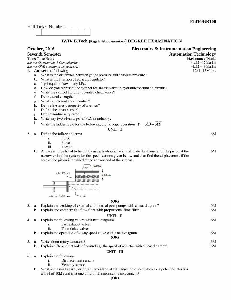
b. A mass is to be lifted to height by using hydraulic jack. Calculate the diameter of the piston at the narrow end of the system for the specifications given below and also find the displacement if the area of the piston is doubled at the narrow end of the system.
6M
(OR)3. a. Explain the working of external and internal gear pumps with a neat diagram? 6M
b. Explain and compare full flow filter with proportional flow filter? 6M
UNIT - II4. a. Explain the following valves with neat diagrams.
i. Fast exhaust valveii. Time delay valve
6M
b. Explain the operation of 4 way spool valve with a neat diagram. 6M(OR)
5. a. Write about rotary actuators? 6Mb. Explain different methods of controlling the speed of actuator with a neat diagram? 6M
UNIT - III6. a. Explain the following.
i. Displacement sensorsii. Velocity sensor
b. What is the nonlinearity error, as percentage of full range, produced when 1kΩ potentiometer has a load of 10kΩ and is at one third of its maximum displacement?
(OR)
7. a. Write various parameters to be considered in selecting a sensor for a given application. 6Mb. Explain the following
i. Hall effect sensorsii. Temperature sensors
6M
UNIT - IV8. a Explain the basic structure of PLC clearly? 8M
b. Write Ladder logic to generate a square wave with 10% duty cycle. 4M(OR)
9. a. Explain about timers and counters in PLC? 7Mb. Device system and write the ladder logic using a PLC, which can be used to control the
movement of the piston in a cylinder using a 4/2 solenoid operated valve. The piston is to move in one direction when a proximity sensor at one end of the stroke closes the contacts and in the other direction when a proximity sensor at the other end of the stroke indicated its arrival there.
5M
October, 2016 Electronics & Instrumentation Engineering Seventh Semester Automation Technology(EI416)
Scheme of Evaluation
Answer all questions
1. a. Pressure measured against the atmospheric pressure is known as gauge pressure.Pressure measured against vacuum is known as absolute pressure.
1M
b. The function of the pressure regulator is to maintain the constant pressure to the loads regardless of flow. Generally the input pressure is high compared to the load pressure to maintain constant pressure to the varying loads..
1M
c. 1 pound per square inch(psi) = 6.895 kPa (kilo pascals) 1Md. symbol for shuttle valve is 1M
e. Symbol for pilot operated check valve is 1M
f. The maximum displacement of the piston in the cylinder or the full travel of the piston along the cylinder is known as stroke length.
1M
g. Meter out speed control: the control mechanism is placed at the load of the system is known as meter out speed control
1M
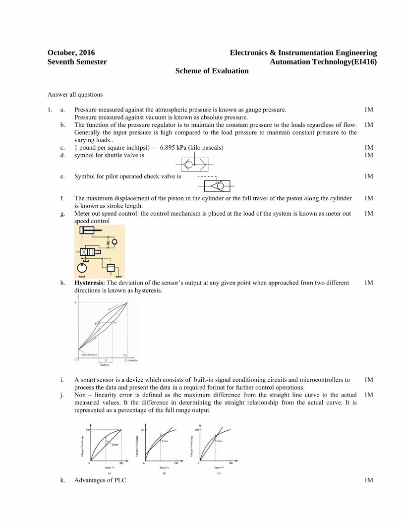
h. Hysteresis: The deviation of the sensor’s output at any given point when approached from two different directions is known as hysteresis.
1M
i. A smart sensor is a device which consists of built-in signal conditioning circuits and microcontrollers to process the data and present the data in a required format for further control operations.
1M
j. Non – linearity error is defined as the maximum difference from the straight line curve to the actual measured values. It the difference in determining the straight relationship from the actual curve. It is represented as a percentage of the full range output.
1M
k. Advantages of PLC 1M
1. It is known as industrial terminal2. Programming is simple with PLC3. It can handle different kinds of devices4. It is very rugged in its operation.
l. 1M
UNIT - I2. a. Force: when a force applied on a mass produces acceleration or deceleration which is directly proportional
to itF = ma.In hydraulic and pneumatic the forces present are due the movement of mass is against the direction or towards the direction of gravitational pull and it is referred as weight. Therefore weight depends on the force of gravity.The units of force in CGS is dynes , MKS are Newtons, FPS are lbs1 kgf one kg force produces an acceleration of 9.8m/sec2.Hence 1Kgf = 9.8N etc.
2M
Power: it is defined as the rate at which the work is doneP = work / time
sec/joulsT
WP or Watts.
SI unit of power watt and is equal to 1Jouls/sec,Imperial system uses the horse power (Hp) and is defined as 550lbf/sec.One horse power is equal to 746W
2M
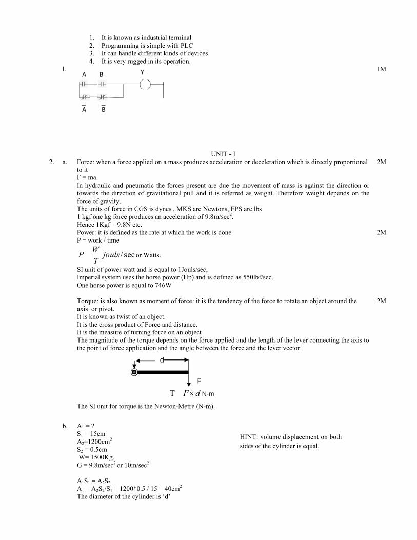
Torque: is also known as moment of force: it is the tendency of the force to rotate an object around the axis or pivot.It is known as twist of an object.It is the cross product of Force and distance.It is the measure of turning force on an object The magnitude of the torque depends on the force applied and the length of the lever connecting the axis to the point of force application and the angle between the force and the lever vector.
dF¥T N-m
The SI unit for torque is the Newton-Metre (N-m).
2M
b. A1 = ?S1 = 15cmA2=1200cm2
S2 = 0.5cmW= 1500Kg.
G = 9.8m/sec2 or 10m/sec2
A1S1 = A2S2
A1 = A2S2/S1 = 1200*0.5 / 15 = 40cm2
The diameter of the cylinder is ‘d’
HINT: volume displacement on both sides of the cylinder is equal.
d
F

Then πd2/4 = 40cm2
Implies d = 7.14cmArea of the piston is doubled thenThen A1 = 80cm2;S1 = 15cmA2 = 1200cm2
S2 = A1S1/A2 = 80*15/1200 =1cmThe displacement is 1cm.
3M
3M
(or)3. a. External gear pump: it is positive displacement pump having two moving parts called gear wheels. These
moving parts are rotating at a constant speed and thus experiences constant force. It consists of just two close meshing gear wheels which rotate as shown below. The direction of rotation of the gears is opposite to each other.As the teeth come out of the mesh at the centre a partial vacuum is formed which draws fluid into the inlet chamber.Fluid is trapped between the outer teeth and the pump housing. Thus continuous transfer of fluid from inlet chamber to the outlet chamber takes place and thus discharges to the system.
Pump displacement is determined by volume of fluid between each pair of teeth; number of teeth; and speed of rotation.It delivers fixed volume of fluid is delivered from the inlet port to the outlet port.Performance of any pump is limited by leakage and the ability of the pump to withstand the pressure differential between inlet and outlet ports.The gear pump requires closely meshing gears, minimum clearance between teeth and housing, and also between the gear face and side plates.Wear in a gear pump is primarily caused by dirt particles in the hydraulic fluid, so cleanliness and filtration are particularly important.Gear pumps are used at pressures up to about 150 bar Volumetric efficiency of gear pumpsat 90%
2M
1M
Internal gear pump is constructed in such a way that an extremely driven gear wheel is connected to a smaller internal gear, with fluid separation as gears disengage being performed by a crescent-shaped moulding.
Working principle is same as that of the external gear pumps.The efficiencies are smaller when compared with the external gear pumps .They operate at low capacities and the efficiencies are lower compared that of external gear pumps.
2M
1M
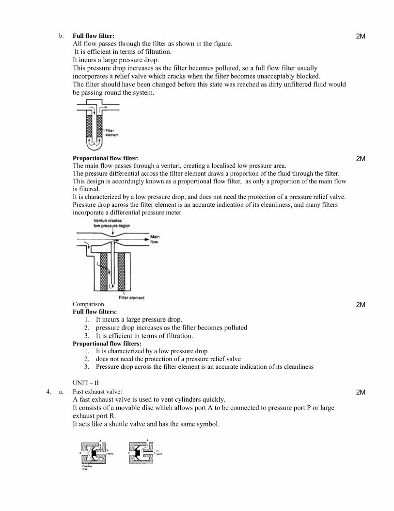
b. Full flow filter:All flow passes through the filter as shown in the figure.It is efficient in terms of filtration.It incurs a large pressure drop. This pressure drop increases as the filter becomes polluted, so a full flow filter usuallyincorporates a relief valve which cracks when the filter becomes unacceptably blocked. The filter should have been changed before this state was reached as dirty unfiltered fluid would be passing round the system.
2M
Proportional flow filter:The main flow passes through a venturi, creating a localised low pressure area. The pressure differential across the filter element draws a proportion of the fluid through the filter. This design is accordingly known as a proportional flow filter, as only a proportion of the main flow is filtered. It is characterized by a low pressure drop, and does not need the protection of a pressure relief valve.Pressure drop across the filter element is an accurate indication of its cleanliness, and many filters incorporate a differential pressure meter
2M
ComparisonFull flow filters:
1. It incurs a large pressure drop. 2. pressure drop increases as the filter becomes polluted3. It is efficient in terms of filtration.
Proportional flow filters:1. It is characterized by a low pressure drop2. does not need the protection of a pressure relief valve3. Pressure drop across the filter element is an accurate indication of its cleanliness
2M
UNIT – II4. a. Fast exhaust valve:
A fast exhaust valve is used to vent cylinders quickly.It consists of a movable disc which allows port A to be connected to pressure port P or large exhaust port R. It acts like a shuttle valve and has the same symbol.
2M
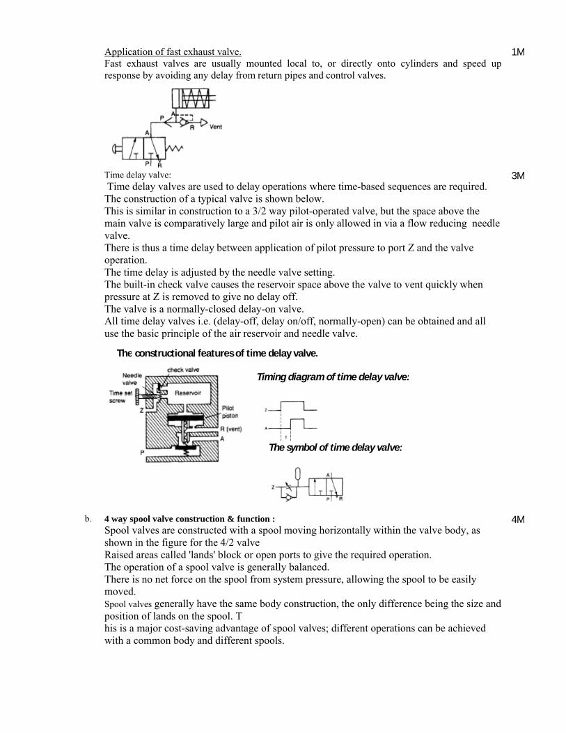
Application of fast exhaust valve.Fast exhaust valves are usually mounted local to, or directly onto cylinders and speed up response by avoiding any delay from return pipes and control valves.
1M
Time delay valve: Time delay valves are used to delay operations where time-based sequences are required.
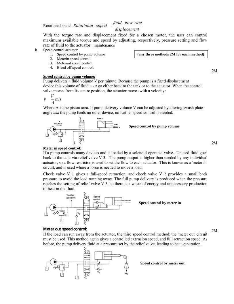
The construction of a typical valve is shown below. This is similar in construction to a 3/2 way pilot-operated valve, but the space above the main valve is comparatively large and pilot air is only allowed in via a flow reducing needlevalve.There is thus a time delay between application of pilot pressure to port Z and the valve operation.The time delay is adjusted by the needle valve setting.The built-in check valve causes the reservoir space above the valve to vent quickly when pressure at Z is removed to give no delay off.The valve is a normally-closed delay-on valve. All time delay valves i.e. (delay-off, delay on/off, normally-open) can be obtained and all use the basic principle of the air reservoir and needle valve.
3M
b. 4 way spool valve construction & function :Spool valves are constructed with a spool moving horizontally within the valve body, as shown in the figure for the 4/2 valve Raised areas called 'lands' block or open ports to give the required operation.The operation of a spool valve is generally balanced. There is no net force on the spool from system pressure, allowing the spool to be easily moved.Spool valves generally have the same body construction, the only difference being the size and position of lands on the spool. This is a major cost-saving advantage of spool valves; different operations can be achieved with a common body and different spools.
4M
The constructional features of time delay valve.
The symbol of time delay valve:
Timing diagram of time delay valve:

Diagram : 2M
(OR)5. a. Rotary actuators:
Rotary actuators are the hydraulic or pneumatic equivalents of electric motors.For a given torque, or power, a rotary actuator is more compact than an equivalent motor, cannot be damaged by an indefinite stall and can safely be used in an explosive atmosphere.A rotary actuator can be defined in terms of the torque.
The torque of a rotary actuator can be specified in three ways.Starting torque is the torque available to move a load from rest.Stall torque must be applied by the load to bring a running actuator to rest.Running torque is the torque available at any given speed. Running torque falls with increasing speed, torque is dependent on the applied pressure; increasing the pressure results in increased torque,as shown.
The running torque falls with increasing speed, so the relationship between power and speed has the form of Figure shown below with maximum power at some (defined) speed. Power like the torque, is dependent on applied pressure.
The torque produced by a rotary actuator is directly related to fluid pressure; increasing pressure increases maximum available torque. Actuators are often specified by their torque rating,
pressure
TorquengTorquerati
Rotational speed is given by:
4 way spool valve: 4 way spool valve symbol:
Power/speed curve for pneumatic rotary actuator
Rotational speed ntdisplaceme
rateflowfluidsppedRotational
With the torque rate and displacement fixed for a chosen motor, the user can control maximum available torque and speed by adjusting, respectively, pressure setting and flow rate of fluid to the actuator. maintenance
b. Speed control actuator:1. Speed control by pump volume2. Meterin speed control3. Meterout speed control4. Bleed off speed control.
Speed control by pump volume:Pump delivers a fluid volume V per minute. Because the pump is a fixed displacementdevice this volume of fluid must go either back to the tank or to the actuator. When the control valve moves from its centre position, the actuator moves with a velocity:
A
Vv m/s
Where A is the piston area. If pump delivery volume V can be adjusted by altering swash plate angle and the pump feeds no other device, no further speed control is needed.
Meter in speed control:If a pump controls many devices and is loaded by a solenoid-operated valve. Unused fluid goes back to the tank via relief valve V 3. The pump output is higher than needed by any individual actuator, so a flow restrictor is used to set the flow to each actuator. This is known as a 'meter in' circuit, and is used where a force is needed to move a load.
Check valve V 1 gives a full-speed retraction, and check valve V 2 provides a small back pressure to avoid the load running away. The full pump delivery is produced when the pressure reaches the setting of relief valve V 3, so there is a waste of energy and unnecessary production of heat in the fluid.
Meter out speed control:If the load can run away from the actuator, the third speed control method; the 'meter out' circuitmust be used. This method again gives a controlled extension speed, and full retraction speed. As before, the pump delivers fluid at a pressure set by the relief valve, leading to heat generation.
2M
2M
2M
Speed control by pump volume
Speed control by meter in
Speed control by meter out
(any three methods 2M for each method)
Bleed off speed control:This speed control method bleed-off valve V 1 is incorporated. This returns a volume v back tothe tank, leaving a volume V-v to go to the actuator where V is the pump delivery volume.Pump pressure is now determined by the required actuator pressure, which is lower than the pressure set on the relief valve. The energy used by the pump is lower, and less heat is generated. The circuit can, however, only be used with a load which opposes motion. Check valve V 2 again gives a small back pressure.
Any unused fluid from the pump is returned to the tank at high pressure leading to wasted energy; even with the more efficient 'bleed'-off circuit. One moral, therefore, is to have a pump delivery volume no larger than necessary.
2M
UNIT – III6. a. Displacement sensor:
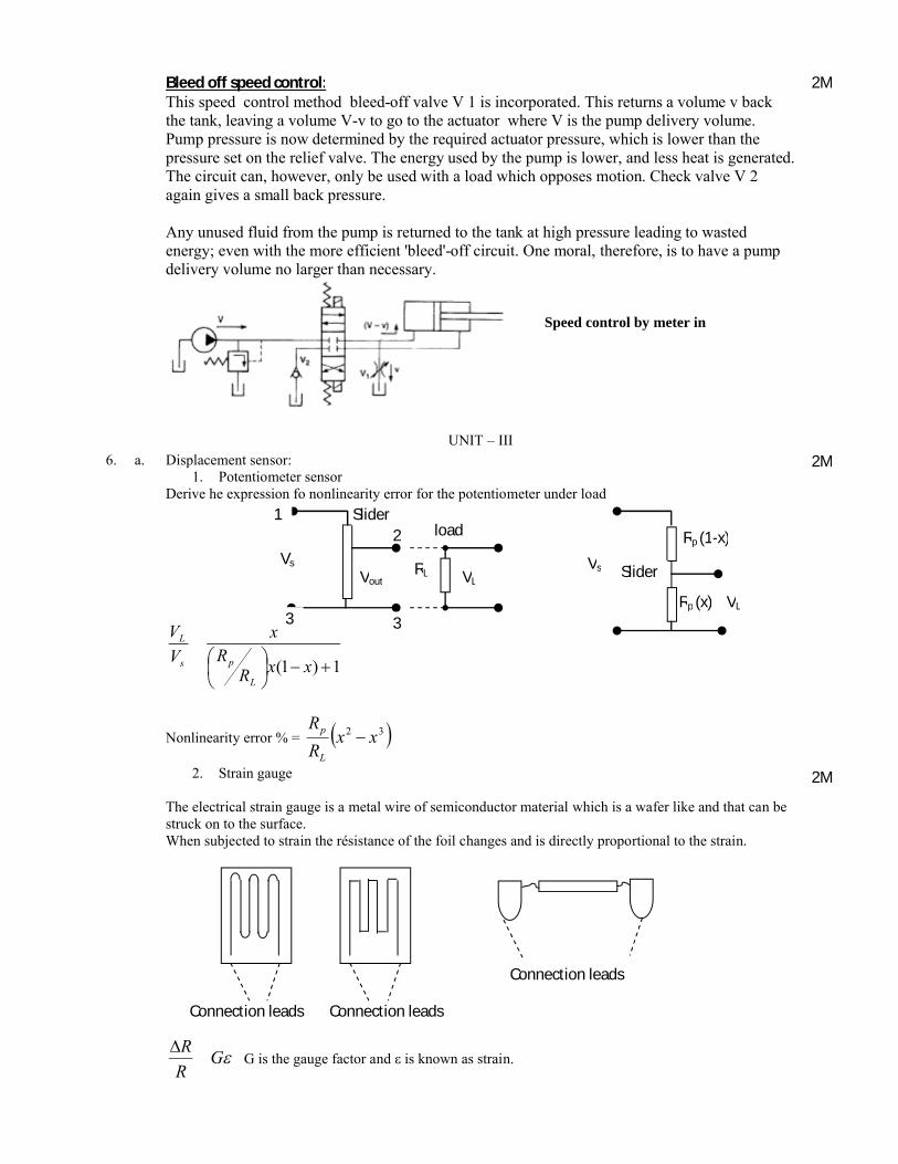
1. Potentiometer sensorDerive he expression fo nonlinearity error for the potentiometer under load
1)1( +-˜¯ˆ
ÁËÊ xxR
Rx
V
V
L
ps
L
Nonlinearity error % = ( )32 xxR
R
L
p -
2. Strain gauge
The electrical strain gauge is a metal wire of semiconductor material which is a wafer like and that can be struck on to the surface.When subjected to strain the résistance of the foil changes and is directly proportional to the strain.
eGR
RDG is the gauge factor and ε is known as strain.
2M
2M
Rp (x)
2
Speed control by meter in
Slider load
VL
Vs
1
3 3
RLVoutSlider
Rp (1-x)
VL
Vs
Connection leads
Connection leads Connection leads
The strain gauge is inserted in the bridge network for the measurement purposes.
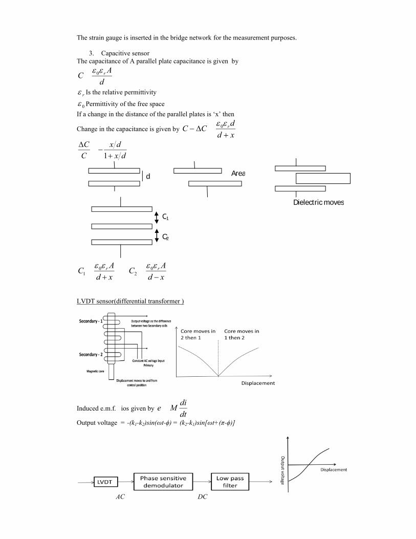
3. Capacitive sensorThe capacitance of A parallel plate capacitance is given by
d
AC ree 0
re Is the relative permittivity
0e Permittivity of the free space
If a change in the distance of the parallel plates is ‘x’ then
Change in the capacitance is given by xd
dCC r
+D-
ee 0
dx
dx
C
C
+-
D1
xd
AC
xd
AC rr
-+eeee 0
20
1
LVDT sensor(differential transformer )
Induced e.m.f. ios given by dt
diMe
Output voltage = -(k1-k2)sin(ωt-ϕ) = (k2-k1)sin[ωt+(π-ϕ)]
AC DC
d Area
Dielectric moves
C1
C2
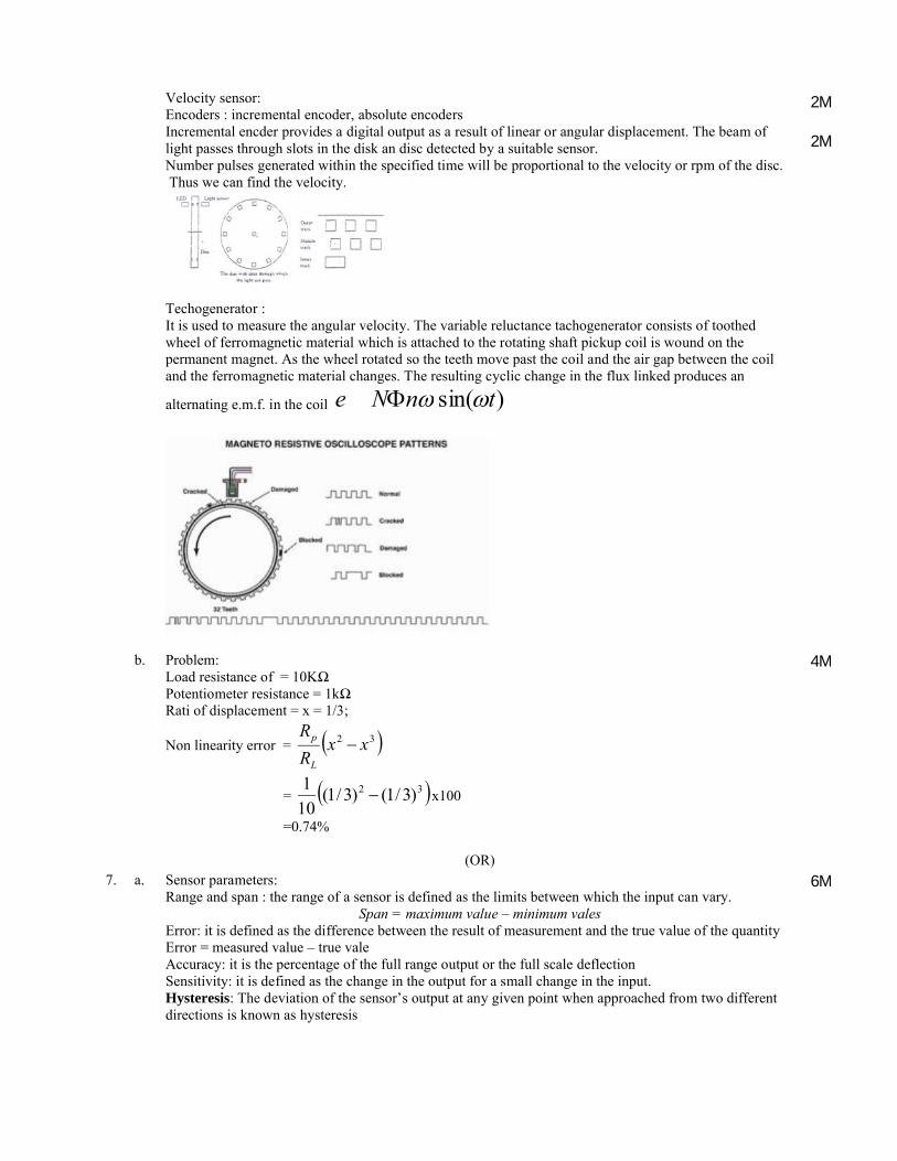
Velocity sensor:Encoders : incremental encoder, absolute encodersIncremental encder provides a digital output as a result of linear or angular displacement. The beam of light passes through slots in the disk an disc detected by a suitable sensor.Number pulses generated within the specified time will be proportional to the velocity or rpm of the disc.Thus we can find the velocity.
Techogenerator :It is used to measure the angular velocity. The variable reluctance tachogenerator consists of toothed wheel of ferromagnetic material which is attached to the rotating shaft pickup coil is wound on the permanent magnet. As the wheel rotated so the teeth move past the coil and the air gap between the coil and the ferromagnetic material changes. The resulting cyclic change in the flux linked produces an
alternating e.m.f. in the coil )sin( tnNe wwF
2M
2M
b. Problem:Load resistance of = 10KΩPotentiometer resistance = 1kΩRati of displacement = x = 1/3;
Non linearity error = ( )32 xxR
R
L
p -
= ( )32 )3/1()3/1(10
1- x100
=0.74%
4M
(OR)7. a. Sensor parameters:
Range and span : the range of a sensor is defined as the limits between which the input can vary.Span = maximum value – minimum vales
Error: it is defined as the difference between the result of measurement and the true value of the quantityError = measured value – true valeAccuracy: it is the percentage of the full range output or the full scale deflectionSensitivity: it is defined as the change in the output for a small change in the input.Hysteresis: The deviation of the sensor’s output at any given point when approached from two different directions is known as hysteresis
6M
Nonlinearity error: Non – linearity error is defined as the maximum difference from the straight line curve to the actual measured values. It the difference in determining the straight relationship from the actual curve. It is represented as a percentage of the full range output.
Repeatability: it is the ability of the transducer to give same output for repeated application of the same input value.Repeatability : (max – min value given)/ full range * 100Stability: it is the ability to give same output when used to measure a constant input over a period of time.Dead band/time : range of input values for which there is no outputOutput impedanceStatic characteristics:Dynamic characteristics: time constant, rise time, settling time etc.
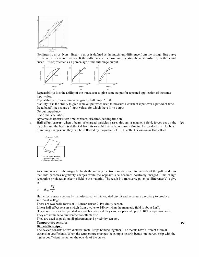
b. Hall effect sensor: when a beam of charged particles passes through a magnetic field, forces act on the particles and the beam is deflected from its straight line path. A current flowing I a conductor is like beam of moving charges and they can be deflected by magnetic field . This effect is known as Hall effect.
As consequence of the magnetic fields the moving electrons are deflected to one side of the palte and thus that side becomes negatively charges while the opposite side becomes positively charged . this charge separation produces an electric field in the material. The result is a transverse potential difference V is give as
t
BIKV H
Hall effect sensors generally manufactured with integrated circuit and necessary circuitary to produce sufficient voltage.There are two basic forms of 1. Linear sensor 2. Proximity sensor.Linear hall effect sensors switch from o volts to 140mv when the magnetic field is about 3mT.These sensors can be operated as switches also and they can be operated up to 100KHz repetition rate.
They are immune to environmental effects also.They are used as position, displacement and proximity sensors.Temperature sensors:Bi metallic strips :The device consists of two different metal strips bonded together. The metals have different thermal expansion coefficients. When the temperature changes the composite strip bends into curved strip with the higher coefficient mental on the outside of the curve.
3M
3M

Resistance temperature detectors:
The resistance of the metals increases over the limited temperature range in a linear way with the increase in the temperature.
)1( tRR ot a+Where Rt is resistance of the material at temperature tα is constant and is termed as temperature coefficient.
Thermistors: These are small pieces of metal made from mixture of metal oxides. (chromium, iron, manganese, and nickel).Thermistors have negative temperature coefficient and is given by
tt KeR
b
Thermistors respond very rapidly to the changes in the temperature and small in size and hence they can be used effectively in the industry.
Thermo couples: Two different metals are joined together. The potential difference depends on the metals used and the temperature of junction.If both the junctions are maintained at the same temperature then the net e.m.f. is zero. The value of the e.m.f. depends on the two metals connected and the temperature‘t’.
2btatE +
UNI T – IV8. a. Basic structure of PLC:
The CPU :The internal structure of the CPU depends on the microprocessor used.1 An arithmetic and logic unit (ALU) which is responsible for data manipulation and carrying out arithmetic operations of addition and subtraction and logic operations of AND, OR, NOT andEXCLUSIVE-OR.2 Memory, termed registers, located within the microprocessor and used to store information involved in program execution.3 A control unit which is used to control the timing of operations.
The buses:1. The data bus carries the data used in the processing carried out by the CPU. A microprocessor
termed as being 8-bit has an internal data bus which can handle 8-bit numbers. It can thus perform operations between 8-bit numbers and deliver results as 8-bit values.
2. The address bus is used to carry the addresses of memory locations. So that each word can be located in the memory, every memory location is given a unique address. Just like houses in a town are each given a distinct address so that they can be located, so each word location is given an address so that data stored at a particular location can be accessed by the CPU either to read data located there or put, i.e. write, data there.
3. The control bus carries the signals used by the CPU for control, e.g. to inform memory devices whether they are to receive data from an input or output data and to carry timing signals used to
2M
2M
2M

synchronise actions.4. The system bus is used for communications between the input/outputports and the input/output
unit.The Memory:
1. System read-only-memory (ROM) to give permanent storage for the operating system and fixed data used by the CPU.
2. Random-access memory (RAM) for the user’s program.3. Random-access memory (RAM) for data. This is where information is stored on the status of input
and output devices and the values of timers and counters and other internal devices.Input/output unit:The input/output unit provides the interface between the system and the outside world, allowing for connections to be made through input/output channels to input devices such as sensors and output devices such as motors and solenoids. It is also through the input/output unit that programs are entered from a program panel.
Every input/output point has a unique address which can be used by the CPU.
The input/output channels provide isolation and signal conditioning functions so that sensors and actuators can often be directly connected to them without the need for other circuitry.
Electrical isolation from the external world is usually by means of optoisolators.
When a digital pulse passes through the light-emitting diode, a pulse of infrared radiation is produced. This pulse is detected by the phototransistor and gives rise to a voltage in that circuit. The gap between the light-emitting diode and the phototransistor gives electrical isolation. but the arrangement still allows for a digital pulse in one circuit to give rise to a digital pulse in another circuit.
2M
b. Write Ladder logic to generate a square wave with 10% duty cycle.
On time = 10 sec and off time = 90sec Duty cycle = 10%
4M
(OR)9. a. Timers:
In many control tasks there is a need to control time. For example, a motor or a pump might need to be controlled to operate for a particular interval of time, or perhaps be switched on after some time interval. PLCs thus have timers as built-in devices. Timers count fractions of seconds or seconds using the internal CPU clock. The timers can be programmed to carry out control tasks.
1. Delay on timers2. Off delay timers
2M

3. Pulse timersThe following figure shows the typical diagram for the three timers
a. On delay timer b. off delay timer c. pulse timer
The following are the representation of timers.
IEC 1131-1 standards. BOOL indicates a Boolean input/output, i.e. on/off. IN is the input. Q is theoutput. ET is the elapsed time output. PT is the input used to specify the time.
The time duration for which a timer has been set is termed the preset and is set in multiples of the time base used. Some time bases are typically 10 ms, 100 ms, 1 s, 10 s and 100 s. Thus a preset value of 5 with a time base of 100 ms is a time of 500 ms.
Counters:Counters are provided as built-in elements in PLCs and allow the number of occurrences of input signals to be counted. This might be where items have to be counted as they pass along a conveyor belt, or the number of revolutions of a shaft, or perhaps the number of people passing through a door. This chapter describes how such counters can be programmed.
A counter is set to some preset number value and, when this value of input pulses has been received, it will operate its contacts.
Down-counters count down from the present value to zero, i.e. events are subtracted from the setvalue. When the counter reaches the zero value, its contacts change state.Up-counters count from zero up to the preset value, i.e. events are added until the number reaches the
preset value. When the counter reaches the set value, its contacts change state.
PLC manufacturers deal with counters in slightly different ways. Some countdown (CTD), or up (CTU), and reset and treat the counter as though it is a relay coil and so a rung output.Counters can consist of two basic elements: one relay coil to count input pulses and one to reset the counter, the associated contacts of the counter being used in other rungs. The above figure illustrates this.
1M
1M
2M
1M
b. Device system and write the ladder logic using a PLC, which can be used to control the movement of the piston in a cylinder using a 4/2 solenoid operated valve. The piston is to move in one direction when a proximity sensor at one end of the stroke closes the contacts and in the other direction when a proximity sensor at the other end of the stroke indicated its arrival there.
5M
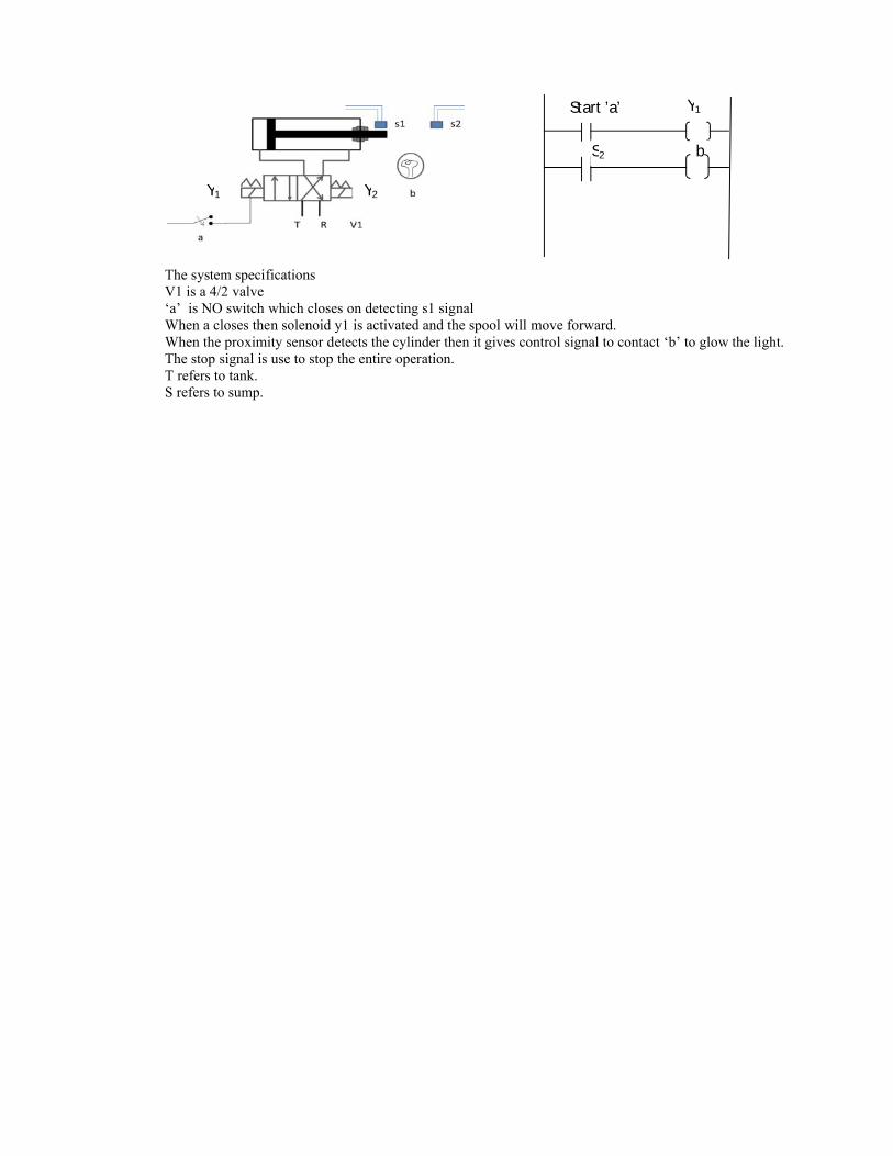
The system specifications V1 is a 4/2 valve‘a’ is NO switch which closes on detecting s1 signalWhen a closes then solenoid y1 is activated and the spool will move forward.When the proximity sensor detects the cylinder then it gives control signal to contact ‘b’ to glow the light.The stop signal is use to stop the entire operation.T refers to tank.S refers to sump.
Y1 Y2
Start ’a’
S2
Y1
b


