
1
1.1 Dry Anaerobic Digestion System Utilising Percolation Dry digestion is well suited to dealing with stackable bio-waste with lower moisture levels, i.e. >20% total solids (TS) and above. These stackable materials can also have high levels of physical contamination and as a result is ideally suited to the processing of co-mingled brown bin material and MSW fines. In this system the incoming feedstock is loaded into “garage” like gas tight biocells using a loading shovel with little or no pre-processing required. These biocells are referred to as fermentation chambers. A summary schematic of the dry fermentation process is illustrated in Fig.1. In brief, bio-waste or biomass is loaded into a sealed, gas tight concrete vessel and this is activated through the spraying of activated anaerobic percolate. This percolate is kept in circulation through an external percolate storage system. The biomass is heated to 37-40oC and biogas production is facilitated. This biogas is drawn off the tunnels and stored prior to use as fuel in a CHP gas engine.
Fig. 1. Schematic of Bioferm dry fermentation system.
The system is modular with increasing tonnages of material being managed by additional fermenters. The fermenters are typically 30m long, 7m wide with an internal stacking height of 3.5m. Each fermenter can typically process 2,500 tonnes of bio-waste per year. Due to the cyclical nature of the biogas production process, the minimum number of fermenters is three. This ensures that there is always biogas available to feed the CHP (Fig. 2). The process of dry fermentation is based on the following procedural steps:
1. Supply and storage of biomass 2. Fermentation 3. Extraction of digestate 4. Ventilation system 5. Gas utilization
For
insp
ectio
n pur
pose
s only
.
Conse
nt of
copy
right
owne
r req
uired
for a
ny ot
her u
se.
EPA Export 28-05-2014:23:44:48

2
Fig. 2. Typical biogas production cycle from a four fermenter facility.
1.1.1 Supply and Storage of Biomass When the plant is operational, the supply of biomass to the fermentation chamber is based on a 28 day cycle. When a chamber is ready for fresh biomass the first step of the exchange requires the extraction of the partially fermented biomass within the chamber. One portion of the extracted biomass is kept on the building floor and then mixed in an approximate ratio with fresh biomass using a front loader (Fig. 3). This ratio will be dictated by the tonnage of material being delivered to the facility and may fluctuate to accommodate seasonal peaks but is expected to be a 50-50 split.
Fig. 3. Filling of a fermentation chamber with Bio-waste.
For
insp
ectio
n pur
pose
s only
.
Conse
nt of
copy
right
owne
r req
uired
for a
ny ot
her u
se.
EPA Export 28-05-2014:23:44:48

3
1.1.2 The Fermentation Chambers Each of the individual fermentation chamber units has an inner floor area of 7m x 30m with an internal height of 5m (Fig. 4). The height of the stacked biomass however, must not exceed 4.0 meters and this is typically managed at 3.5m. The reinforced concrete fermentation chamber is gas tight to prevent the infiltration of oxygen (the presence of which would cause the methane producing bacteria to become inactive). This also prevents the leakage of biogas. An in-floor heating system holds the biomass at a constant temperature of 37-40°C. The plant engineering components are located in a dedicated technology section housed above the fermenters, the capture and storage of biogas is managed through a stainless steel piped biogas ventilation system while short to medium term gas storage bags are also located above the fermentation chambers. The percolate from the fermenters is stored in two insulated and heated tanks.
Fig. 4. Interior of fermenter prior to filling (left) and with bio-waste prior to fermenter sealing.
To insure that the fermentation chamber is not opened before the methane gas is completely drawn from the chamber and safe atmospheric levels of CO2 and H2S are reached, the air inside the chamber is continuously measured and analysed. The values are communicated to the computerized security system controlling the chamber doors. With the exception of loading and unloading biomass from the fermentation chambers, the entire plant is fully automated by PLC. Interruptions are immediately recognised and documented.
1.1.3 Percolate Cycle The dry fermentation process is facilitated by the “percolate cycle”. This involves the spraying of the biomass with an activated anaerobic sludge that is developed in a separate heated tank. This percolate inoculates the biomass while keeping it moist (>70% moisture). While the process of hydrolysis (discruption of cellular walls) is initiated during storage of the fresh biomass within the reception building, both acidogenisis and methanogenesis steps
For
insp
ectio
n pur
pose
s only
.
Conse
nt of
copy
right
owne
r req
uired
for a
ny ot
her u
se.
EPA Export 28-05-2014:23:44:48
4
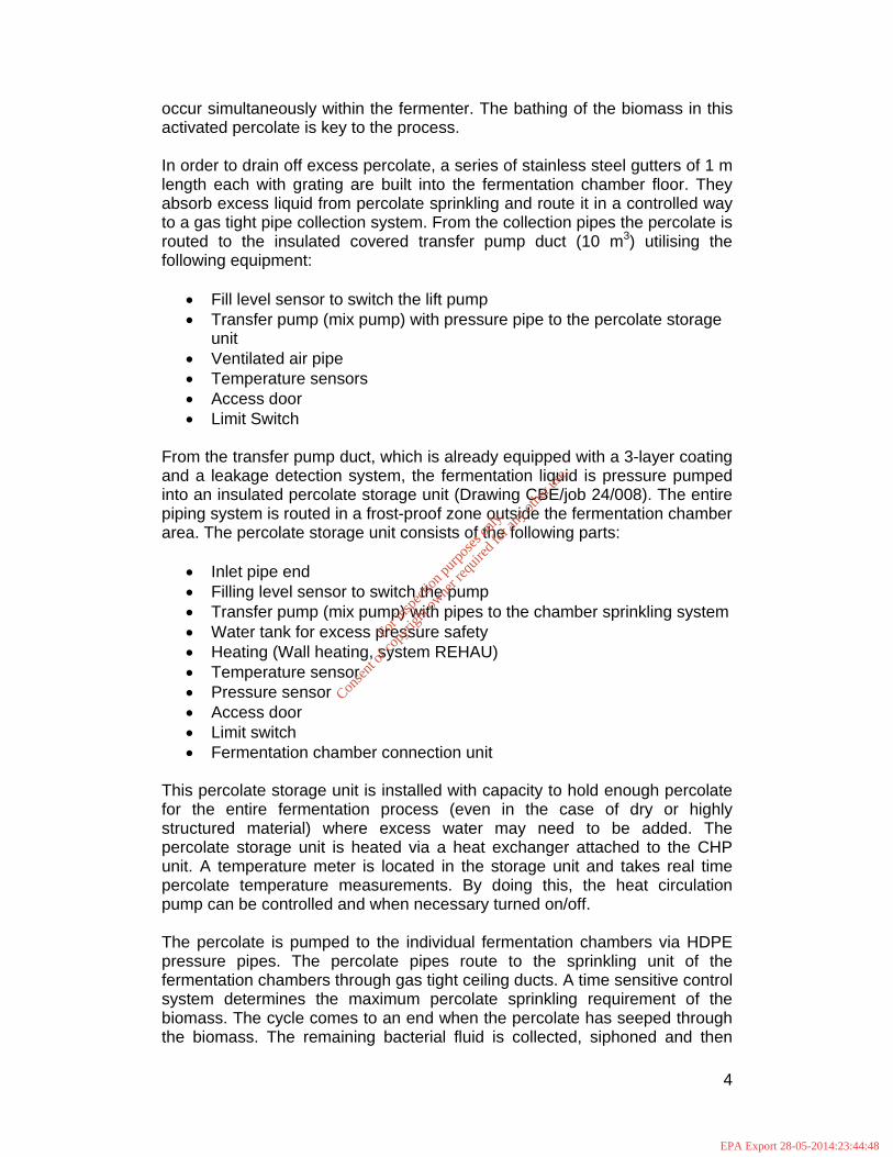
occur simultaneously within the fermenter. The bathing of the biomass in this activated percolate is key to the process. In order to drain off excess percolate, a series of stainless steel gutters of 1 m length each with grating are built into the fermentation chamber floor. They absorb excess liquid from percolate sprinkling and route it in a controlled way to a gas tight pipe collection system. From the collection pipes the percolate is routed to the insulated covered transfer pump duct (10 m3) utilising the following equipment:
Fill level sensor to switch the lift pump Transfer pump (mix pump) with pressure pipe to the percolate storage
unit Ventilated air pipe Temperature sensors Access door Limit Switch
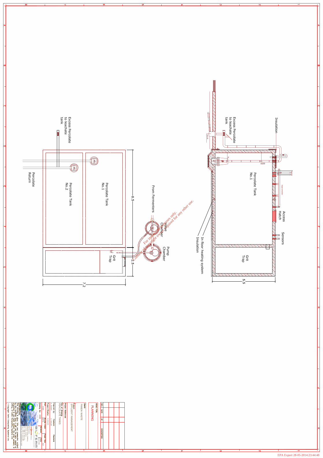
From the transfer pump duct, which is already equipped with a 3-layer coating and a leakage detection system, the fermentation liquid is pressure pumped into an insulated percolate storage unit (Drawing CBE/job 24/008). The entire piping system is routed in a frost-proof zone outside the fermentation chamber area. The percolate storage unit consists of the following parts:
Inlet pipe end Filling level sensor to switch the pump Transfer pump (mix pump) with pipes to the chamber sprinkling system Water tank for excess pressure safety Heating (Wall heating, system REHAU) Temperature sensor Pressure sensor Access door Limit switch Fermentation chamber connection unit
This percolate storage unit is installed with capacity to hold enough percolate for the entire fermentation process (even in the case of dry or highly structured material) where excess water may need to be added. The percolate storage unit is heated via a heat exchanger attached to the CHP unit. A temperature meter is located in the storage unit and takes real time percolate temperature measurements. By doing this, the heat circulation pump can be controlled and when necessary turned on/off. The percolate is pumped to the individual fermentation chambers via HDPE pressure pipes. The percolate pipes route to the sprinkling unit of the fermentation chambers through gas tight ceiling ducts. A time sensitive control system determines the maximum percolate sprinkling requirement of the biomass. The cycle comes to an end when the percolate has seeped through the biomass. The remaining bacterial fluid is collected, siphoned and then
For
insp
ectio
n pur
pose
s only
.
Conse
nt of
copy
right
owne
r req
uired
for a
ny ot
her u
se.
EPA Export 28-05-2014:23:44:48

5
transported using the transfer pump duct. This is to ensure that the percolate cannot leave the system in an uncontrolled manner. The percolate tanks and pumping chambers are monitored by the facility SCADA system which monitors flow and is equipped with level alarms (Fig. 5).Should the gauge in the percolator storage unit fall below the minimum level required for fermentation of exceptionally dry biomass, fresh water or suitable effluents can be added to the percolation tanks. As a general rule the percolate level should be balanced as the percolate is recycled and stored in the final storage chamber. Excessively wet input substrates may result in the production of excess percolate. This excess would be pumped to the adjacent effluent tank No. 1.
Fig. 5. Siemens SCADA control of the percolate tank at the Moosdorf facility in Bavaria.
1.1.4 Heating Less than 5% of the heat ngenerated from the CHP engine is utilised to maintain the working temperature within the fermenters; the rest can be used for external purposes. The thermal energy from the CHP engine is passed to a heat-exchanging device whose operating temperature averages around 85°C. By means of turnouts and heating pumps, warm water is channeled though the heating system of the biogas plant. The fermentation system is conducted at mesophilic temperatures of around 37-40° C. Heat is transported through stainless steel pipes. The fermentation chamber floor is equipped with heat piping so that the temperature of the fermenting material is
For
insp
ectio
n pur
pose
s only
.
Conse
nt of
copy
right
owne
r req
uired
for a
ny ot
her u
se.
EPA Export 28-05-2014:23:44:48

6
maintained at 37-40° C. The placement of the heat distributor alongside the heat in-feed of the percolate storage units ensures against excess heat exchanges.
1.1.5 Pneumatic Controls The compressor produces the required compressed air to activate all pneumatic valves and it is regulated with an on/off switch. The air pressure lines are routed to a distribution manifold to facilitate individual valve requirements. In the case of pressure loss or a controlled emergency stop, all pneumatic valves are depressurised automatically through a closing mechanism, using the spring-break principle, thus securing the plant in a safe operating state and preventing uncontrolled gas leaks. Pneumatic valves are activated by the air pressure from the respective chambers: The chamber door is manually opened and closed. When the door is closed, it is pneumatically locked. Compression couplings generate the necessary surface pressure and use it to assure the chamber remains gas tight. In order to open the fermentation chamber door, clamping screws require loosening and a pneumatic release device needs to be operated by hand. Only when gas quantities of ≤ 3 % CH4, < 0.5 % CO2 and > 18 % O2 are measured in the fermentation chamber is approval to open the door given via the PLC system (green indicator on control panel). The pneumatic lock on the chamber door can then only be opened with a key. There is a finite time limit within which the chamber door must be opened. If the door is not opened during the allowed time a new approval sequence must be given by the PLC control system based on the content of methane and oxygen in the fermentation chamber.
1.1.6 Gas Measurement and Storage After loading the fermentation chambers, the biomass is kept undisturbed for a period of approximately four weeks, during which time the biomass is anaerobically fermented and biogas is produced. The gas quality (CH4, CO2, H2S and O2) is determined with a gas analysis device and communicated to the PLC system and the Siemens SCADA software interface (Figs. 6 & 7). The plant operating parameters such as temperature, pressure, gas quantity and quality are stored in a database. Percolate quantity, valve and plant conditions (fermentation chamber, gas storage, CHP) are monitored via the PLC. The biogas is extracted from the chamber with an explosion and leak proof ventilation mechanism and it is routed into the gas storage unit located on top of the fermentation chambers (Fig. 8). The internal pressure of the gas storage unit under normal operating conditions is maintained at a maximum of 5 mbar. For safety reasons the internal pressure of the gas storage unit must never exceed 25 mbar. This is controlled by the PLC with a further mechanical pressure relief valve that routes the excess biogas to a flare. The gas storage bag is designed with enough capacity to buffer the biogas even
For
insp
ectio
n pur
pose
s only
.
Conse
nt of
copy
right
owne
r req
uired
for a
ny ot
her u
se.
EPA Export 28-05-2014:23:44:48

7
during offline maintenance works on the degasification units of the plant or the CHP unit. When the degasification unit or the CHP unit comes back online the buffered gas can be reprocessed. Under normal operation the gas storage units are loaded to a maximal of 30 - 40 % of capacity via the level control sensor to guarantee enough buffer capacity for operational disturbances.
Fig. 6. Siemens SCADA control of fermenter. No.1 at the Moosdorf facility in Bavaria.
By mixing the streams of gas from different fermentation chambers a gas with consistent methane content is produced. Due to this process the methane content of the mixed gas will be the average of the combined fermentation chambers thus achieving higher process stability. A minimum mixed gas methane content of 57% aspired to. The desulphurisation of the gas is achieved automatically by the PLC control system. A hydrogen sulfide level of less than ≤ 100 ppm is desired. The moist biogas stays in the gas storage unit for a period of time while cooling to ambient temperature. During this process the water in the gas condenses and is transferred via a siphon water duct (150 mm) from the deepest point of the gas storage unit to the fermentation chamber below. This is process is referred to as passive condensation extraction. Further biogas production takes place in the percolate storage tank. A connection to a fermentation chamber is installed on the ceiling of the percolate storage tank and the biogas is exhausted via a gas compressor. The gas is condensed and routed to the gas storage unit.
For
insp
ectio
n pur
pose
s only
.
Conse
nt of
copy
right
owne
r req
uired
for a
ny ot
her u
se.
EPA Export 28-05-2014:23:44:48

8
Fig. 6. Siemens SCADA control of gas storage at the Moosdorf facility in Bavaria.
Continuous measurement of CH4, CO2, H2S and O2 levels and gas volume for each individual fermentation chamber as well as the volume and composition of the mixed gas in the gas storage unit is carried out to monitor the line operation. This is essential for optimal control of all processes and any interruptions can be detected and prevented at an early stage.
Fig. 8. The pneumatic gas collection system on the roof of the fermenters (left) and the gas transfer blower to the gas bag (right).
A fermentation chamber gas extraction unit consisting of the following components is attached to each fermentation chamber on a gas tight ceiling conduit:
For
insp
ectio
n pur
pose
s only
.
Conse
nt of
copy
right
owne
r req
uired
for a
ny ot
her u
se.
EPA Export 28-05-2014:23:44:48

9
Valve to the CHP Valve for the gas collection pipes with gas meter. Hydraulic safety valve for vacuum and pressure gauge
1.1.7 Fermenter Ventilation System The ventilation system provides sufficient ventilation for the fermenter chamber opening process. Ventilation is accomplished with a controlled piping system (stainless steel, resistant to methane gas and electrical conductivity), backpressure valves and ventilation units. The exhaust air within both the fermentation chamber is combined with compost exhaust and the building air which is ultimately discharged to the atmosphere via a bio-filter.
1.2 CHP The biogas from the dry fermentation system is mixed with the biogas generated from wet fermentation. The CHP unit is supplied with biogas from the gas storage unit via an individual gas control valve and gas compressor. The CHP units are installed in a separate, noise dampened containerised unit (Fig. 9). The electricity produced by the CHP units is fed into the public grid and/or used for internal consumption. The thermal energy generated by the CHP units is needed in small amounts as process heat (approx. 5 %) in the plant (in-floor heating of wet and dry fermentation chambers, heating of buildings etc.). In cases where the thermal energy is not used, the CHPs are equipped with a standard emergency cooling mechanism.
Fig.9. Containerised CHP at the Decker biogas plant in Northern Germany
The accessories to the gas engines include the compressors, fire and smoke detectors within the room, a separate electrical control cabinet and remote control that enable the supplier to check the biogas engines on a daily basis or according to requirements. Exhaust gas emissions will be in accordance with European standards. Details can be adjusted for local requirements. Noise and exhaust gas quality are based on European regulations. All the safety design is according to German Safety Regulations for Agricultural Biogas Plants. In a situation where the gas engines are out of operation due to maintenance or repair, an emergency flare burns the surplus biogas. The emergency flare has a fully covered flame and is automatically turned on by the level control of the gas holder. It burns biogas at about 800 – 850 °C and follows international standards for this duty.
For
insp
ectio
n pur
pose
s only
.
Conse
nt of
copy
right
owne
r req
uired
for a
ny ot
her u
se.
EPA Export 28-05-2014:23:44:48
1
T E C H N I C A L M E M O R A N D U M C e l t i c B i o E n e r g y
Waste Water Management Memo
PREPARED FOR: Panda Waste
PREPARED BY: Andrew Walsh, CBE
COPIES: Michael Watson, O’Callaghan Moran
Eamon Waters, Panda Waste
David Naughton, Panda Waste
Michael O’Gorman, CBE
DATE: August 15th 2009
Introduction: The Panda Waste bio-waste facility will generate a number of effluents that must be managed in a manner that does not lead to pollution of waters, flooding and does not result in pathogen cross-contamination within the facility. The facility is also configured in accordance with sustainable urban drainage (SUDS) and with a focus on maximum effluent re-use in the facility in order to minimize the hydraulic and BOD load of effluents exported from the site. As the facility does not have a discharge license, the facility is being designed to maximize the re-use of effluents within the process with excess effluents being collected by tanker and delivered to a waste water treatment plant for appropriate treatment. As part of the process design, an effluent mass balance has been prepared. The rainfall data is taken from historical information from Dublin Airport weather and from 1:25 year storm events with a one hour return. Effluents: The effluents generated on site are listed in Table 1 below and are categorized based on flow, pollutant load and pathogen transmission potential.
Table 1: Panda Bio-Waste Effluents
Effluent Flow Organic Loading Pathogen Risk
Fermenter percolate MBT Low High High
Fermenter percolate Bio-waste
Low High High
Compost tunnel leachate MBT
Low / Moderate
High High
Compost tunnel leachate Bio-waste
Low / Moderate
High High
Building floor wash-down Moderate High High
Biofilter & scrubber effluent Moderate Moderate /Low Low
External pavement storm water
Moderate/High Low / Moderate Low
Roof storm water Moderate/High Low Low MBT: Mechanical Biological Treatment inputs (mixed waste) Bio-waste: Source separated food and green waste inputs
For
insp
ectio
n pur
pose
s only
.
Conse
nt of
copy
right
owne
r req
uired
for a
ny ot
her u
se.
EPA Export 28-05-2014:23:44:48

2
The Effluent Stores The effluent storage capacities are detailed in Table 2.
Table 2. Capacities of effluent management stores at the Panda Waste Facility.
Store Contents Net volume
Roof water tank Roof water from bio-waste building (existing steel tank)
660 m3
Percolate tank 1 MBT dry fermentation percolate (New concrete tank)
200 m3
Percolate tank 2 Bio-waste dry fermentation percolate (New concrete tank)
200 m3
Effluent tank 1 Tunnel leachate & wash down (New steel tank)
320 m3
Effluent tank 2 Odour abatement effluent tank (New steel tank)
700 m3
Effluent Mass Balance: The effluent mass balance for the high strength effluents is detailed in Table 3. It contains information on the low and high flow scenarios for the effluents generated. These flows are influenced by the seasonal presentation of bio-waste at the facility. The mass balance of effluent generation for the odour abatement system is illustrated in table 4. A schematic diagram of the effluent management system for the facility is illustrated in drawing attached (CCS/Job 24/007/Effluent Schematic).
Table 3. Monthly Effluent Mass Balance for Panda Bio-waste Facility effluent tank No. 1 (m3/month)
Effluent Low flow High Flow
Bio-waste percolate (5) (10)
MBT percolate (50) (70)
Bio-waste tunnels 15 25
MBT tunnels 15 25
Watering of bio-waste tunnel compost (7.5) (10)
Watering of MBT tunnel compost (7.5) (10)
Floor wash-down 25 35
Vehicle wash-down 45 55 TOTAL EFFLUENT OFF SITE 30 40
Table 4. Monthly Effluent Mass Balance for Panda Bio-waste Facility effluent tank
No. 2 (m3/month)
Effluent Low flow High Flow
Biofilter effluent 55 65
Scrubber effluent 90 110
TOTAL EFFLUENT OFF SITE 145 175
Roof Water Management The total roof area for the facility is 12,183 m2. Storm water from the roof will be directed to a pump chamber to be stored within an existing above ground storage
For
insp
ectio
n pur
pose
s only
.
Conse
nt of
copy
right
owne
r req
uired
for a
ny ot
her u
se.
EPA Export 28-05-2014:23:44:48

3
tank with a capacity of 660 m3. This reservoir will be used as a primary source of non-potable water at the site for wash down, odour abatement, dust suppression and sanitary purposes. The tank capacity will allow for twice the storage capacity
required for a 1:25 year storm event (26.57mm/hr 60min duration rainfall event = 324 m3). In addition, given mean monthly winter rainfall in the area, roof water flows are likely to average between 800 and 1,000 m3 per month. The subsequent grey water re-use within the facility (odour abatement & wash down) will utilize approximately 25-30% of this water thus preserving equivalent amounts of potable water (Table 5).
Table 5. Principal roof water re-uses (m3/month)
Use Low flow High Flow
Biofilter 70 100
Scrubber 90 110
Floor wash-down 25 35
Vehicle wash-down 45 55
TOTAL 230 300
Pavement Storm Water Management: Given the low pollution and pathogen potential of clean storm water from the surrounding paved areas, this water will discharge directly to a soakaway via a Class 1 petrol interceptor located adjacent to the facility (Planning Drawing No. 2009-101-103). Percolate Management The percolate tanks are active anaerobic reactors that will be net users of water that will be sourced from the effluent tank No. 1. In the event of excess percolate being produced, this will be pumped to effluent tank No. 1. Fermenter Percolate Management (MBT) Seven of the 14 dry fermentation chambers will be utilized for the processing of mixed waste (MBT). Due to the relatively dry nature of this material (approx. 52% moisture) and the target moisture content of 68% during fermentation, there will be a net moisture deficit of between 50-70 m3/month in the process where the net water generation resulting from hydrolysis being overweighed by the initial water deficit. Fermenter Percolate Management (Bio-waste) Seven of the 14 dry fermentation chambers will be utilized for the processing of source separated food and green waste (bio-waste). Given the target moisture content of 68% during fermentation and the typical moisture content of the incoming material (approx. 60%), there will be a deficit in the effluent generation of approximately 5-10 m3/month. Effluent tank No. 1 Management Internal Floor Wash-Down
For
insp
ectio
n pur
pose
s only
.
Conse
nt of
copy
right
owne
r req
uired
for a
ny ot
her u
se.
EPA Export 28-05-2014:23:44:48

4
The internal floor area of the facility (excluding interior of processing vessels and vehicle wash down areas is 4,200 m2. Wash down of these floors is expected to generate approximately 25-35 m3 of effluent per month. Vehicle Wash-Down There are two main vehicle wash down areas within the building. Given the expected incoming traffic at the design capacity, the truck wash down is expected to generate approximately 45-55 m3/month at full design capacity. Tunnel Leachate Management (MBT) Post-fermentation, the solid state MBT material is transferred to four aerobic tunnels where a net generation of 15-25 m3 of leachate will be produced over the duration of the retention, i.e. 28 days. In addition, during the final two weeks of composting, it is expected that the material in the tunnels will run at a moisture deficit and as a result, it is expected that the process will consume 7.5-10m3/month. This water will be sourced from the odour abatement effluent storage tank to minimize off-site disposal of high strength liquors. Tunnel Leachate Management (Bio-waste) Post-fermentation, the solid state bio-waste is transferred to four aerobic tunnels where a net generation of 15-25 m3 of leachate will be produced over the duration of the retention, i.e. 28 days. In addition, during the final two weeks of composting, it is expected that the material in the tunnels will run at a moisture deficit and as a result, it is expected that the process will consume 7.5-10m3/month. This water will be sourced from the odour abatement effluent storage tank to minimize off-site disposal of high strength liquors. Effluent tank No. 2 (Odour Abatement Effluents) The odour abatement system consists of a wet acid scrubber in tandem with a biofilter operating in tandem. The biofilter is designed to operate in bio-trickling mode with the recirculation of the effluent. The scrubber effluent will generate up to 90 – 110 m3/month with the bio-trickling filter generating a net 55-65 m3/month.
For
insp
ectio
n pur
pose
s only
.
Conse
nt of
copy
right
owne
r req
uired
for a
ny ot
her u
se.
EPA Export 28-05-2014:23:44:48
For
insp
ectio
n pur
pose
s only
.
Conse
nt of
copy
right
owne
r req
uired
for a
ny ot
her u
se.
EPA Export 28-05-2014:23:44:48


