© 2017 Cisco Systems, Inc. All rights reserved. This document is Cisco Public Information.
Dell PowerEdge FX2: Beware of the Density Paradox
Solution BriefFebruary 2017
Rack-level power and cooling budgets define data center density—not your server design.At first, the Dell PowerEdge FX2 density message may seem intriguing. When you take a closer look, however, you find that a smaller form factor does not provide the promised benefits you may hope for. And although Dell markets the FX2 as a high-density computing product, most data centers can’t take advantage of the density because of power and cooling limitations. You instead end up with partially filled racks and servers that are compromised, with less availability, capability, airflow, and power supply capacity. These limitations affect performance and add more complexity to your environment than if you deployed Cisco Unified Computing System™ (Cisco UCS®) servers. Are you willing to make that compromise?
Density Is Limited by Power and Cooling ConstraintsRack-level capacity (power, cooling, and space) determines the amount of IT equipment that can be deployed in each rack.
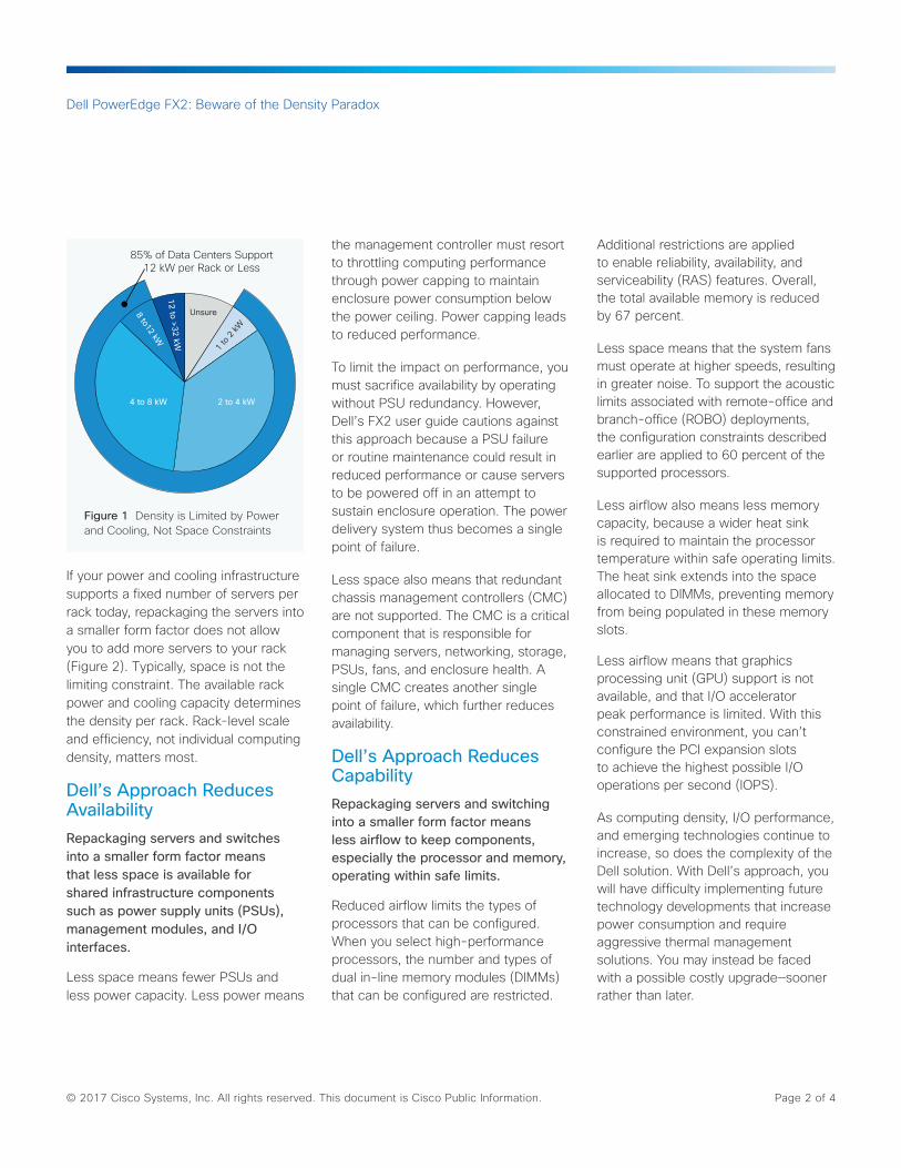
According to the presentation “An Industry-Wide Look at the Data Center Ecosystem of 2025” at the Data Center World Global Conference 2015, 85 percent of all data centers today support 12 kilowatts (kW) or less per rack, and the average capacity is about 6 kW per rack (Figure 1), With hyperdense solutions like the Dell PowerEdge FX2, in the overwhelming majority of cases the available rack power and cooling capacity is exhausted before the available rack space. Thus, packaging servers into a smaller form factor does not automatically enable more servers or cores per rack in real-life data centers. In general, equivalently configured servers will consume the same amount of power—regardless of form factor.
Highlights
Dell’s Approach• Is limited by rack power and cooling• Reduces availability• Reduces memory capacity• Reduces performance• Increases complexity
Additional Servers or Cores per Rack
0
Up to
Less Power Capacityper Server
Up to
Less Memory per Perver
IncreasedDensity Means
60%
68%
Dell PowerEdge FX2: Beware of the Density Paradox
© 2017 Cisco Systems, Inc. All rights reserved. This document is Cisco Public Information. Page 2 of 4
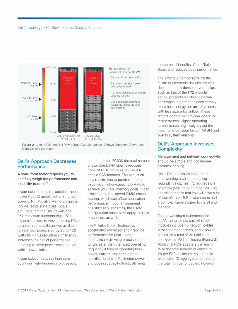
If your power and cooling infrastructure supports a fixed number of servers per rack today, repackaging the servers into a smaller form factor does not allow you to add more servers to your rack (Figure 2). Typically, space is not the limiting constraint. The available rack power and cooling capacity determines the density per rack. Rack-level scale and efficiency, not individual computing density, matters most.
Dell’s Approach Reduces AvailabilityRepackaging servers and switches into a smaller form factor means that less space is available for shared infrastructure components such as power supply units (PSUs), management modules, and I/O interfaces.
Less space means fewer PSUs and less power capacity. Less power means
the management controller must resort to throttling computing performance through power capping to maintain enclosure power consumption below the power ceiling. Power capping leads to reduced performance.
To limit the impact on performance, you must sacrifice availability by operating without PSU redundancy. However, Dell’s FX2 user guide cautions against this approach because a PSU failure or routine maintenance could result in reduced performance or cause servers to be powered off in an attempt to sustain enclosure operation. The power delivery system thus becomes a single point of failure.
Less space also means that redundant chassis management controllers (CMC) are not supported. The CMC is a critical component that is responsible for managing servers, networking, storage, PSUs, fans, and enclosure health. A single CMC creates another single point of failure, which further reduces availability.
Dell’s Approach Reduces CapabilityRepackaging servers and switching into a smaller form factor means less airflow to keep components, especially the processor and memory, operating within safe limits.
Reduced airflow limits the types of processors that can be configured. When you select high-performance processors, the number and types of dual in-line memory modules (DIMMs) that can be configured are restricted.
Additional restrictions are applied to enable reliability, availability, and serviceability (RAS) features. Overall, the total available memory is reduced by 67 percent.
Less space means that the system fans must operate at higher speeds, resulting in greater noise. To support the acoustic limits associated with remote-office and branch-office (ROBO) deployments, the configuration constraints described earlier are applied to 60 percent of the supported processors.
Less airflow also means less memory capacity, because a wider heat sink is required to maintain the processor temperature within safe operating limits. The heat sink extends into the space allocated to DIMMs, preventing memory from being populated in these memory slots.
Less airflow means that graphics processing unit (GPU) support is not available, and that I/O accelerator peak performance is limited. With this constrained environment, you can’t configure the PCI expansion slots to achieve the highest possible I/O operations per second (IOPS).
As computing density, I/O performance, and emerging technologies continue to increase, so does the complexity of the Dell solution. With Dell’s approach, you will have difficulty implementing future technology developments that increase power consumption and require aggressive thermal management solutions. You may instead be faced with a possible costly upgrade—sooner rather than later.
85% of Data Centers Support12 kW per Rack or Less
Unsure
1 to
2 kW
2 to 4 kW4 to 8 kW
8 to12 kW
12 to >32 kW
Figure 1 Density is Limited by Power and Cooling, Not Space Constraints
Dell PowerEdge FX2: Beware of the Density Paradox
© 2017 Cisco Systems, Inc. All rights reserved. This document is Cisco Public Information. Page 3 of 4
Dell’s Approach Decreases PerformanceA small form factor requires you to carefully weigh the performance and reliability trade-offs.
If your solution requires additional ports, native Fibre Channel, higher Ethernet speeds, Non-Volatile Memory Express (NVMe) solid-state disks (SSDs), etc., note that the Dell PowerEdge FX2 enclosure supports eight PCIe expansion slots. However, adding PCIe adapters reduces the power available to each computing sled by 25 to 100 watts (W). This reduction significantly increases the risk of performance throttling to keep power consumption within power limits.
If your solution requires high core counts or high-frequency processors,
note that in the FC630 the total number of available DIMM slots is reduced from 24 to 16, or to as few as 8 to enable RAS features. This reduction may require you to purchase more expensive higher-capacity DIMMs to achieve your total memory goals. It can also lead to unbalanced DIMM channel loading, which can affect application performance. If your environment has strict acoustic limits, the DIMM configuration constraints apply to basic processors as well.
Intel® Turbo Boost Technology accelerates processor and graphics performance for peak loads, automatically allowing processor cores to run faster than the rated operating frequency if they’re operating below power, current, and temperature specification limits. Restricted power and cooling capacity drastically limits
the potential benefits of Intel Turbo Boost and reduces peak performance.
The effects of temperature on the failure of electronic devices are well documented. A dense server design, such as that of the FX2 modular server, presents significant thermal challenges. It generates considerably more heat energy per unit of volume, with less space for airflow. These factors contribute to higher operating temperatures. Higher operating temperatures negatively impact the mean time between failure (MTBF) and overall system reliability.
Dell’s Approach Increases ComplexityManagement and network connectivity should be simple and not require complex cabling.
Dell’s FX2 enclosure implements a networking architecture using redundant switches (I/O aggregators) or simple pass-through modules. This approach means that you will have a lot of top-of-rack (ToR) switch ports and a complex cable system to install and manage.
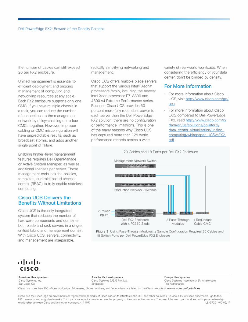
The networking requirements for a LAN using simple pass-through modules include 16 network cables, 2 management cables, and 2 power cables, or a total of 20 cables, to configure an FX2 enclosure (Figure 3). Additional PCIe adapters can easily raise the total number of cables to 28 per FX2 enclosure. You can use expensive I/O aggregators to reduce the total number of cables. However,
Same Number ofServers Consume 10 kW
• Same workload run on both
• Same rack density (server and core) for both
• No more rack power or cooling capacity for both
• Dell’s approach sacri�ces availability, capability, and performance
Dell PowerEdge FX228 x FC630
Cisco UCS28 x B200 M4
Maximum Power14.8 kW
20 kW
UnusableRack
Space
UnusableRack
Space15 kW
10 kW
5 kW
0 kW
Average Power10.7 kW
Idle Power4.4 kW
Figure 2 Cisco UCS and Dell PowerEdge FX2 Comparison Shows Equivalent Server and Core Density per Rack
Americas Headquarters Cisco Systems, Inc. San Jose, CA
Asia Pacific Headquarters Cisco Systems (USA) Pte. Ltd. Singapore
Europe Headquarters Cisco Systems International BV Amsterdam, The Netherlands
Dell PowerEdge FX2: Beware of the Density Paradox
Cisco has more than 200 offices worldwide. Addresses, phone numbers, and fax numbers are listed on the Cisco Website at www.cisco.com/go/offices.
Cisco and the Cisco logo are trademarks or registered trademarks of Cisco and/or its affiliates in the U.S. and other countries. To view a list of Cisco trademarks, go to this URL: www.cisco.com/go/trademarks. Third party trademarks mentioned are the property of their respective owners. The use of the word partner does not imply a partnership relationship between Cisco and any other company. (1110R) LE-57201-00 02/17
the number of cables can still exceed 20 per FX2 enclosure.
Unified management is essential to efficient deployment and ongoing management of computing and networking resources at any scale. Each FX2 enclosure supports only one CMC. If you have multiple chassis in a rack, you can reduce the number of connections to the management network by daisy-chaining up to four CMCs together. However, improper cabling or CMC misconfiguration will have unpredictable results, such as broadcast storms, and adds another single point of failure.
Enabling higher-level management features requires Dell OpenManage or Active System Manager, as well as additional licenses per server. These management tools lack the policies, templates, and role-based access control (RBAC) to truly enable stateless computing.
Cisco UCS Delivers the Benefits Without LimitationsCisco UCS is the only integrated system that reduces the number of hardware components and combines both blade and rack servers in a single unified fabric and management domain. With Cisco UCS, servers, connectivity, and management are inseparable,
radically simplifying networking and management.
Cisco UCS offers multiple blade servers that support the various Intel® Xeon® processors family, including the newest Intel Xeon processor E7-8800 and 4800 v4 Extreme Performance series. Because Cisco UCS provides 60 percent more fully redundant power to each server than the Dell PowerEdge FX2 solution, there are no configuration or performance limitations. This is one of the many reasons why Cisco UCS has captured more than 125 world performance records across a wide
variety of real-world workloads. When considering the efficiency of your data center, don’t be blinded by density.
For More Information• For more information about Cisco
UCS, visit http://www.cisco.com/go/ucs
• For more information about Cisco UCS compared to Dell PowerEdge FX2, read http://www.cisco.com/c/dam/en/us/solutions/collateral/data-center-virtualization/unified-computing/whitepaper-UCSvsFX2.pdf
2 PowerInputs
Management Network Switch
20 Cables and 18 Ports per Dell FX2 Enclosure
Production Network Switches
Dell FX2 Enclosurewith 4 FC360 Sleds
2 Pass-ThroughModules
1 RedundantCable CMC
Figure 3 Using Pass-Through Modules, a Sample Configuration Requires 20 Cables and 18 Switch Ports per Dell PowerEdge FX2 Enclosure


