Water Research Pergamon Press 1972. Vol. 6, pp. 503-505. Printed in Great Britain
CONTROL OF THE ANAEROBIC DIGESTION PROCESS AND SUPPORTING UNIT PROCESSES
C. F. GUARINO City of Philadelphia, Water Department, 1160 Municipal Services Building,
Philadelphia, Pa. 19107, U.S.A.
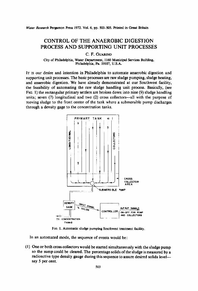
IT IS our desire and intention in Philadelphia to automate anaerobic digestion and supporting unit processes. The basic processes are raw sludge pumping, sludge heating, and anaerobic digestion. We have already demonstrated at our Southwest facility, the feasibility of automating the raw sludge handling unit process. Basically, (see FiG. 1) the rectangular primary settlers are broken down into nine (9) sludge handling units; seven (7) longitudinal and two (2) cross collectors---all with the purpose of moving sludge to the front center of the tank where a submersible pump discharges through a density gage to the concentration tanks.
P R I M A R Y T A N K
,~
t J I
- - CROSS _ ~ = ~ COLLECTOR
AREA
7 _ . . . . . . . . . . .
NTROLLER ON-OFF FOR PUMP ~ _ AND COLLECTORS
TO CONCENTRATION TANKS
hG. I. Automatic sludge pumping Southwest treatment facility.
In an automated mode, the sequence of events would be:
(1) One or both cross collectors would be started simultaneously with the sludge pump so the sump could be cleared. The percentage solids of the sludge is measured by a radioactive type density gauge during this sequence to assure desired solids level-- say 5 per cent.
503

504 C.F. GuARrNo
(2) As the sludge thins out, longitudinal flights are turned on sequentially until the desired solids level is attained.
(3) At times, the sludge will be too thick. Sludge thinning is accomplished by dilution water.
If the above system were installed in all four of Southwest's primary tanks, after step 3, controllers would initiate the full procedure in an adjacent tank. The system at present is installed to control primary tank No. 1. We are assured of uniform sludge removal from the entire tank floor using the outlined system.
We feel that the second unit process, sludge heating, can be easily automated. Basically, the system would call for direct digester charging of primary sludge, temperature monitoring of all digesters and temperature adjustment via circulation of digester sludge through sludge heaters of the heat exchanger variety. Philadelphia has had considerable operating experience with temperature monitoring and sludge heating equipment. Since 1968 at our Southwest facility, two (2) 1.26 million kg-cal h-1 (5 million BTU h- i ) heat exchanger sludge heaters have been operating satisfactorily. Philadelphia also has been monitoring sludge temperatures in digesters and sludge lines since 1954. All of this experience will form the basis of plans for automated sludge heating.
Philadelphia feels that anaerobic digestion--though highly complex----can be automated. The key to digester control is the measurement of digester gas for CO2. In Philadelphia, going back to 1951, operating records confirm that CO2 change is sufficiently sensitive to determine the condition of a well mixed digester. For digester control, accurate on-line measurement of CO2 is therefore a necessity.
Since 1962, Philadelphia has used a Ranarex indicator at our Southwest facility to monitor percent CO2. This instrument is a gas analyzer which measures the specific gravity of a gas or gas mixture compared to air. Since a definite relationship exists between CO2 and the specific gravity of a gas mixture, the scale and chart can be graduated to read in percentage CO2. This instrument over the past nine years has required very little maintenance and compares excellently with simultaneous Orsatt measurements (see TABLE 1).
With the provision to measure C02 on-line, Philadelphia's digester control scheme will be structured as follows:
(1) Providing adequate space is available, raw sludge will be directly charged to the digester with the most favorable CO2 level and gas rate.
(2) While being charged or shortly thereafter, the digester will be mixed via a gas recirculation system.
(3) If the temperature of the charged digester is below an established limit, the digester will be recirculated through sludge heaters.
(4) After temperature correction, the digester is allowed settling time before super- natant or bottom sludge is withdrawn.
To test this scheme under simulated computer controlled conditions, we have engaged the services of the General Electric Company. The scope of the joint project covers:
(1) Development of an operational flow chart.

Control of the Anaerobic Digestion Process
TABLE I. COMPARISON OF ORSATT AND RANAREX INSTRUMENTS FOR MEASUREMENT
OF PERCENTAGE CO2 SOUTHWEST TREATMENT PLANT DIGESTER GAS, JUNE 1963
505
Day Orsatt Ranarex % %
3 36.6 35.5 4 36.0 36.0 5 43.2 42.5 6 32.4 31.5 7 33.2 33.0 8 33.4 32.0
10 40.2 40.0 11 33.8 33.0 12 34.6 35.5 13 35.8 34.0 14 35.0 33.0 15 34.6 32.5 17 31.8 30.5 18 34.6 34.0 19 34.4 34.0 20 35.8 35.0 21 32.6 30.5 22 37.6 37.0 24 34.8 33.0 25 34.4 33.5 26 32.8 31.5 27 36.4 36.5 28 43.4 43.0 29 35.6 35.0
Average 35.5 per cent 34.7 per cent
Average deviation 2.25 per cent
(2) Develop and debug a computer program which will control the operation of all digesters.
(3) Install a remote terminal at the Northeast Treatment facility for communication via telephone lines with a private process control computer.
(4) Program evaluation and modification based on operational data.
The four part control scheme will be applied simultaneously to at least eight (8) separate digester tanks, each with a capacity exceeding 7570 m 3 (two million U.S. gallons). Laboratory tests such as pH, volatile acids, and alkalinity will be manually inserted into the control program and used as a secondary source of priority establish- ment for digester charging. Completion of this project will give Philadelphia more insight into the problems associated with computer control of detailed unit processes, particularly anaerobic digestion. Preliminary design work is now in progress for the expansion of our three (3) treatment facilities. All three expanded plants are scheduled to be in operation by the fall of 1977. The plants will have capacities ranging from 946,000 to 454,000 m 3 day-1 (250--120 mgd). As the design work progresses, existing and additional information relative to plant automation will be integrated into con- struction specifications and drawings.


